

Unipro 6003 User Manual
Reference Manual
Unipro Laptimer
6003
Version 1.00
15. March 2009
Go faster faster
UNIPRO ApS
VIBORG HOVEDVEJ 24
DK-7100 VEJLE
DENMARK
Tel.: +45 75 85 11 82
Fax: +45 75 85 17 82
www.uniprolaptimer.com
mail@uniprolaptimer.com

Introduction.............................................................................................................................6
General Information................................................................................................................7
History of Unipro..................................................................................................................................7
Philosophy...........................................................................................................................................7
Commonly used words........................................................................................................................8
Baud (bps) ................................................................................................................ 8
Display...................................................................................................................... 8
DSP (digital signal processing)...................................................................................... 8
Filter......................................................................................................................... 8
First lap .................................................................................................................... 8
Infrared .................................................................................................................... 8
IrDA ......................................................................................................................... 8
Logging..................................................................................................................... 8
Loop......................................................................................................................... 8
LEd Lamps................................................................................................................. 9
Magnet stripe............................................................................................................. 9
Main box ................................................................................................................... 9
Memory .................................................................................................................... 9
Processor .................................................................................................................. 9
Protocol .................................................................................................................... 9
Receiver.................................................................................................................... 9
Trigger...................................................................................................................... 9
Telemetry.................................................................................................................. 9
Receiver types...................................................................................................................................10
Loop (AMB) ..............................................................................................................10
Magnet (stripe) .........................................................................................................10
IR (infrared) .............................................................................................................10
Split types..........................................................................................................................................10
Splits with magnet stripes...........................................................................................11
Splits with wheel sensor .............................................................................................11
Communication types........................................................................................................................11
Serial.......................................................................................................................11
IrDA ........................................................................................................................11
USB.........................................................................................................................12
Laptimer functions ...............................................................................................................13
Turning Laptimer on...........................................................................................................................13
Turning Laptimer off...........................................................................................................................13
Clearing all.........................................................................................................................................13
Low battery warning...........................................................................................................................14
RPM calculation.................................................................................................................................14
Speed measurement .........................................................................................................................15
Instantaneous method...............................................................................................................................15
Data stored........................................................................................................................................16
Logging..............................................................................................................................................17
Analysing your data...........................................................................................................................18
Data Analyser ...........................................................................................................18
PC Analyser ..............................................................................................................18
UNIPRO – The original Laptimer 2

Laptimer Overview................................................................................................................19
About the Display Unit.......................................................................................................................19
How to use the display unit................................................................................................................20
Display buttons .........................................................................................................20
The Main Box.....................................................................................................................................21
Connectors ........................................................................................................................................21
RPM.........................................................................................................................21
WHEEL.....................................................................................................................21
TEMP 1 ....................................................................................................................22
TEMP 2 ....................................................................................................................22
TEMP 3 ....................................................................................................................22
RECV 1 ....................................................................................................................22
RECV 2 ....................................................................................................................22
AUX.........................................................................................................................22
USB.........................................................................................................................22
DISP........................................................................................................................22
Installation..........................................................................................................................................23
Display unit ..............................................................................................................23
Main box ..................................................................................................................24
RPM sensor...............................................................................................................26
Receivers .................................................................................................................26
AMB Loop receiver ....................................................................................................................................26
Magnet receiver........................................................................................................................................27
Infrared receiver.......................................................................................................................................28
Temperature sensors .................................................................................................28
Cylinder head sensor.................................................................................................................................28
Exhaust sensor .........................................................................................................................................29
Water sensor............................................................................................................................................29
Wheel sensor kit........................................................................................................30
The sensor disc.........................................................................................................................................30
The wheel sensor ......................................................................................................................................31
Laptimer setup......................................................................................................................33
Engine timers.....................................................................................................................................33
Wheel circumference.........................................................................................................................34
Tire wear counters.............................................................................................................................34
Temperature inputs............................................................................................................................35
Temperature warning points..............................................................................................................35
Shift light............................................................................................................................................36
Receiver type.....................................................................................................................................36
Magnet setup.....................................................................................................................................36
Magnet count............................................................................................................37
Magnet delay ............................................................................................................37
Split points.........................................................................................................................................38
Splits with magnet stripes...........................................................................................39
Undo Clear split points! ..............................................................................................39
Splits with wheel sensor .............................................................................................40
Viewing the split points ..............................................................................................40
Editing the split points................................................................................................41
Typical track with 6 split points...................................................................................................................41
Display setup.....................................................................................................................................42
UNIPRO – The original Laptimer 3

Set left and right side of the lower part .........................................................................42
Example with chosen information.................................................................................42
Minimum and maximum time between two trigs (retrig delay)...........................................................42
Low delay.................................................................................................................42
Display contrast ........................................................................................................43
Display language.......................................................................................................44
Setup in Service Mode.......................................................................................................................44
Last data..................................................................................................................44
Last temperatures.....................................................................................................................................44
General information ...................................................................................................44
Lap length and theoretical best lap time........................................................................45
Laptimer statistics .....................................................................................................45
Laptimer information..................................................................................................45
Laptimer diagnostic....................................................................................................45
Engine, RPM and speed measurement settings...............................................................46
Laptimer setup – Communication.................................................................................46
Laptimer setup - LED intensity.....................................................................................46
Laptimer setup - Temperature.....................................................................................46
Laptimer setup - speed type.......................................................................................46
Laptimer setup - Off time............................................................................................46
Laptimer switches - Split light .....................................................................................47
Split times display .....................................................................................................47
Logger setup.............................................................................................................47
Show at new lap........................................................................................................47
Software update........................................................................................................47
How to use the Laptimer in different operating modes.....................................................48
Setup mode .......................................................................................................................................48
Service Mode.....................................................................................................................................48
Undo mode........................................................................................................................................48
First lap mode....................................................................................................................................49
Running mode ...................................................................................................................................50
Pit mode.............................................................................................................................................51
Normal data view ......................................................................................................51
Graphical data view ...................................................................................................51
PC mode............................................................................................................................................52
Split measure mode...........................................................................................................................52
Defining the split points with the use of the wheel sensor................................................52
Time run mode...................................................................................................................................53
Maintenance..........................................................................................................................54
Changing batteries.............................................................................................................................54
Updating................................................................................................................................54
Finding the current version................................................................................................................54
Update with a PC...............................................................................................................................55
Trouble Shooting..................................................................................................................56
The Laptimer is turned on, but do not register the lap time...............................................................56
The Laptimer does not measure correct speed/split..........................................................................56
The PC is reporting a none standard USB device plugged in! ..........................................................56
UNIPRO – The original Laptimer 4

The RPM value is excessively high!..................................................................................................56
UNIPRO – The original Laptimer 5

Introduction
Thank you for trusting us to deliver the most advanced Laptimer on the market.
This Manual includes detailed information about your Unipro Laptimer. If you need a quick
overview of the functions, and a guide to the daily use, you may want to look at the QuickGuide
first.
The Unipro Laptimer has several unique features and will measure every piece of information with
a speed and accuracy you have only dreamt about! It really enables you to use your Laptimer as a
tool to go faster, faster.
We did all we could to make your investment as future proof as possible and you should be able to
enjoy it in many years to come. Therefore it is possible to expand the Laptimer with new
accessories as they are being developed.
If you have a special request either for new accessories or for a new feature, please let us know.
We constantly try to develop our products with the most useful features so you can use the
Laptimer to go faster, faster but we always appreciate good ideas from the users of our products.
If you have any problems or questions regarding your Unipro Laptimer we will make sure to give
you the necessary support.
Please e-mail your questions to
Good luck on the tracks!
UNIPRO ApS
Viborg Hovedvej 24
DK-7100 Vejle
Denmark
Web:
E-mail: mail@uniprolaptimer.com
www.uniprolaptimer.com
support@uniprolaptimer.com or contact your local dealer.
UNIPRO – The original Laptimer 6

General Information
History of Unipro
Unipro was founded in 1987 after inventing the world’s first Laptimer. It could only measure lap
times and was produced in very small quantities. We still have one of the first six Laptimers
produced and of course it is still working – after more than 20 years! In 1991 we did something
people said couldn’t be done. We build the first Laptimer with RPM sensing integrated. This really
helped the drivers to see how their engine was performing. In 1996, we made the first Laptimer
with two temperature inputs and many other features not seen before. We made the unique split
feature using a wheel sensor to divide the track into different segments (up to 9 segments), a
digital signal processing of the RPM signal giving the most precise RPM value ever seen. You could
even connect a portable, battery driven printer to the Laptimer and get all you valuable
information on paper! In 2002, we decided to reinvent the Unipro Laptimer from scratch again!
Your Unipro Laptimer is a result of this reinvention. We have made so many new inventions and
features that we can’t get into them here, but now you really can use the Laptimer as a tool to go
faster, faster!
Philosophy
People often ask us why we make Laptimers the way we do and we would like to tell you about
our philosophy:
Our top models will always have a separate display
There are several positive sides and only one negative side to this:
• It enables us to make an ultra thin display unit with a very appealing design
• It will keep all the cables needed away from the steering wheel and thereby enable the
driver to drive the kart!
• It enables us to use two separated processors and keeping at lot of processing power free
for the advanced calculations needed to give you the precise data we offer.
• The only negative side about the separated systems is that the cost is higher!
We will only make systems with enough buttons
There are so many features at your fingertips, but if your Laptimer has to few buttons, it will be
difficult to find the needed features fast enough. We will always make sure that the Unipro
Laptimer has enough buttons so it is fast and easy to operate.
We use as much energy on the cables and sensors as on the Laptimer itself
Every cable is hand built with the finest cable and finest connectors. We will not try to make
money on spare parts that has to be replaced very often. We build every part of the Laptimer with
the intention that it should never break !
UNIPRO – The original Laptimer 7

Commonly used words
Throughout this manual, we use many technical words and terms. In this section we will explain
the most commonly used technical words.
BAUD (BPS)
Baud is another word for bit per seconds (bps). It tells you how many bits can be moved in a wire
or in the air per second. Speeds of 115200 baud can in theory move 11520 bytes per second.
Baud is used to measure serial speed, normally known from RS232.
DISPLAY
The display is also known as the LCD, monitor or screen.
DSP (DIGITAL SIGNAL PROCESSING)
Analogue signals are transformed into digital signals and then processed in a computer. This is
called DSP and it can be done in a dedicated processor called a DSP or in a normal processor like
the one used in the Laptimer. Using DSP algorithms, it is possible to do a lot of advanced
processing.
FILTER
Remove something unwanted. One example of the use of filters in your Laptimer, is to remove
unwanted noise when the RPM of your engine is measured.
FIRST LAP
The first part of the race. It is the segment from the pit to the finish line. It is sometimes called
the out lap. This segment of the track is important because it is used to align the Laptimer to the
finish line.
INFRARED
Invisible light beam in the infrared band. Normally just referred to as IR. The remote control for
your TV or stereo also uses infrared light.
IRDA
Infrared Data Association. This is an infrared communication standard used in Laptops, PDAs,
PalmPilots, mobile phones, printers and a lot more. The IrDA standard is both physical hardware
and software.
LOGGING
Logging is storing data continues in a memory. The idea of logging is to store everything for later
analysis – in the pit or on your PC.
LOOP
A Loop is a wire in the asphalt. The Loop is sending a signal that the Laptimer pick up every time
it passes the loop. The Loop must be an active AMB Loop in order to trigger the Laptimer.
UNIPRO – The original Laptimer 8

LED LAMPS
A LED or Light Emitting Diode is a rather simple semiconductor circuit which emits light without
producing waste heat. This means, it needs only very little energy, about 5% of a normal light
bulb to produce the same amount of light. We use ultra bright LEDs as warning lamps in the
display unit.
MAGNET STRIPE
A piece of magnet going all the way across the track. Used to trigger the Laptimer as an
alternative to the loop.
MAIN BOX
Most of the electronic is located in the main box. This is the box wit h all the connectors, memory
and batteries.
MEMORY
A lot of different memory is used for storing the program, setup, lap times and logged data. The
most used type of memory is Flash or EEPROM. Both types are used in this Laptimer.
PROCESSOR
The part of the Laptimer with all the intelligenc e and calculating power. It is also called a CPU, μP,
μC or just the computer.
PROTOCOL
A protocol is a piece of software that sets the standard for how the systems work. For example
the process for sending data through infrared light is defined in the Infrared Data Association
Protocol – the IrDA protocol.
RECEIVER
The receiver picks up the trigger signal and starts the Laptimers stopwatch. There are different
types of receivers: loop, magnet stripe and infrared. Your Unipro Laptimer supports all kinds of
receivers.
TRIGGER
The Laptimer trigs when it passes the finish lin e. The trigger can be either infrared light, a magnet
stripe or a Loop signal.
TELEMETRY
A way of sending data through the air from the running kart to the pit. It is illegal during official
races and can only be used for training.
UNIPRO – The original Laptimer 9

Receiver types
The Unipro Laptimer supports all kind of receivers. The different receivers are good for different
things, and sometimes you need to change between several types. Unfortunately, none of them is
perfect. We have made a short list of pros and cons of the different receiver types.
LOOP (AMB)
9 Very precise trig
9 Long sensing distance.
9 Full electronic systems without any problems at all.
9 Not sensitive to vibrations.
9 Use very little power in the Laptimer.
2 AMB active Loop only. Will not work on a passive Loop.
2 Sometimes the Loop is turned off.
2 Only one on a track. Cannot be used for splits like several stripes.
MAGNET (STRIPE)
9 Very precise trig.
9 Can have more than one on a track for splits.
9 Use very little power in the Laptimer.
2 Mechanical system.
2 Can in worst case generate false trigs with excessive vibrations.
IR (INFRARED)
9 Can be used where no Loop or Magnets are present.
9 Can be used far from the asphalt.
2 Not as precise trig because the beam is spreading across the track.
2 Can miss a trig if another driver is covering the infrared beam.
2 Beam can hit the kart more than once on the track.
2 Need an IR transmitter placed on the track.
2 Use power in the Laptimer.
Unipro recommends using the Loop receiver. This is the perfect receiver type if there is an active
AMB Loop present at the track. Second choice is the Magnet receiver, but if you are at a race on a
car park, the IR receiver is needed.
Split types
Dividing the track into smaller sections is one of the most important features of the Laptimer. It
will help drivers at every level and in every type of kart to go faster, faster. There are two ways of
using splits with your Unipro Laptimer:
1. Splits with magnet stripes
2. Splits with wheel sensor
UNIPRO – The original Laptimer 10

SPLITS WITH MAGNET STRIPES
If the track has more than one magnet stripe, it is possible to use the rest as split points. The
problem with this method is that you do not have enough split points and you cannot place them
yourself. You will no longer be able to view corner information because you typically have several
corners per segment. Therefore you should only use the magnet stripes as split points if you are
using a kart with four-wheel brakes.
SPLITS WITH WHEEL SENSOR
Using the high precision wheel sensor, you can define up to 8 points on the track as split points.
This will divide the track in up to 9 segments giving you the possibility to optimize your kart setup
and driving style for each segment of the track individually. You can set the splits in setup mode,
during the first lap, wireless from the Data Analyser or using the USB cable from the PC Analyser
program.
Communication types
An important feature of a Laptimer is the communication between the Laptimer and other devices.
Typically you will use the Laptimer on the track for quick analysis, but if you want to go deeper
into the analysis, you need to get the data away from the Laptimer to a PC or printer. This section
describes the different communication standards.
SERIAL
Serial communications is normally referred to as RS232. It is a low speed, wire interface standard
used in old Laptimers. RS232 is still used from the Data Analyser to the portable DPU printers, but
the RS232 port is now removed from most modern Laptops. The speed typical ranges between
9600 baud and 115.200 baud.
IRDA
IrDA is a shortcut for Infrared Data Association. It is a standard for communicating with invisible
light. IrDA is a standard consisting of many levels. The lower ones describe the physical link. This
is the one with use for communicating between the Laptimer and the Data Analyser. The physical
speed is 115.200 baud, but because of overhead with error detections and retransmission, the
real payload is around 75% of the theoretical limit.
With the higher levels of the IrDA protocol, it is possible to communicate with PDAs, PalmPilots,
Laptops, mobile phones and many other devices. It is possible to choose the full IrDA protocol in
the Laptimer, enabling it to talk directly with a P DA. The higher levels add a lot of overhead, and
it will lower the real speed of the transfer. The protocol is either a primary (master) or secondary
(slave). Unipro uses a secondary protocol in the Laptimer and a primary protocol in the Data
Analyser. The distance for an IrDA link is normally around 30 – 100 cm (10“ – 40“) but it is very
depending on the surroundings. Fluorescent light and sun light will limit the possible range.
UNIPRO – The original Laptimer 11

USB
USB is a shortcut for Universal Serial Bus and is a pure PC standard. It is a high-speed serial link
with two different speeds: USB 1.1 with a maximum speed of 12Mbps and USB 2.0 with a
maximum speed of 480Mbps. The standard is divided into hosts (master) and devices (slave).
Both the Unipro Laptimer and the Data Analyser are devices. In a system, a host is always needed
and that is why it is not possible to connect the Laptimer to the Data Analyser using the USB
cable! A future standard, called USB on the Go will combine the two things, enabling equipment to
be both a host and a device.
For none standard USB equipment to be used on a PC, a USB device driver is needed. The USB
standard is a plug and play standard, and the PC will find new equipment when it is plugged into
the USB port on the PC. The first time it will try to find a driver and install it. After that, you just
plug the USB device in and out as you like, even with the power on.
UNIPRO – The original Laptimer 12

Laptimer functions
In this chapter we explain the basic functions of the Laptimer and the reason for why we have
built it the way we have.
Turning Laptimer on
Turning the Laptimer on is done with the button. During
power-on, the display will turn on all segments and the 5
LEDs will blink to show start-up is in progress.
During the startup, the batteries are checked and the main
box tries to communicate with the display unit. If they c
find each other, the Laptimer turns off again.
Turning Laptimer off
To manually turn the Laptimer off, press and hold for
more than one second. You will see the display go blank
when the Laptimer is turning off.
If no signal is present at the RPM input (engine stopped) the
Laptimer will automatically be turned off after 5 minutes.
annot
Clearing all
Clearing all data in the Laptimer is easy!
Turn the Laptimer on an press the button for three
seconds to clear all the data stored in the Laptimer. If this is
done by accident, you can use UNDO mode to undo it again!
After doing clear laps, the Laptimer starts in firstlap mode
ready to drive again.
No settings are cleared, only the laps and the logged data! We recommend clearing the Laptimer
after each run. If you have too many laps in the Laptimer, it will get harder to analyse your data.
Transfer the data to the Data Analyser or a PC before you clear the laps. Please remember, that
the logged data can only be transferred to a PC, and not to the Data Analyser.
UNIPRO – The original Laptimer 13

Low battery warning
The Laptimer is constantly measuring the battery voltage and if the voltage drops too much, a
battery-warning icon is shown in the display. There are three diff erent warning levels before the
Laptimer turns off:
Indication Battery voltage What to do
This is an early warning. Do not change the
Turned on
Blinks
Display blinks > 1.60 V
> 1.90 V
> 1.80 V
batteries yet, but wait until the icon starts to
blink. Batteries are expensive and not good for
the environment. Please wait as long as possible.
Now it is time to change the batteries. When the
icon starts to blink.
This is the last chance to change the batteries
without loosing any data.
RPM calculation
Different Laptimers have very different ways of calculating the RPM. The Unipro Laptimer use a
very advanced method. The result is very precise calculation of the RPM. A very simplified
explanation of the difference is that:
2 Some Laptimers counts each pulse to the spark plug, and calculates a new RPM value for
each 0.6 seconds – a total of 10 new RPM values per second.
9 Unipro Laptimers use an advanced processor that measures the time between pulses to the
spark plug. This method results in up to 350 new RPM values per second.
2 Some Laptimers calculates the RPM without any kind of filter on the signal from the spark
plug. Since there is a lot of unwanted noise, this method is not very precise.
9 Unipro Laptimers uses an advanced two-way filter technology, of our own invention, to
filter the signal from the spark plug. This method results in a very precise calculation.
UNIPRO – The original Laptimer 14
Speed measurement
The speed measurement is an important feature in the Unipro Laptimer. We have made our speed
kit in a very high quality, in order to give you a precise measurement of:
• Your speed, so you can see the effect on changes in your driving style or kart set-up
• The tire wear
• The lap length
• The split points that divides the track into different sections
The measurement of speed can be done in different ways. Some Laptimers use a method where
the speed is calculated using the RPM combined with input about the gearing and wheel
circumference. Other Laptimers counts the number of pulses from a wheel sensor in a certain
amount of time, and then calculates the average speed during the period. The main disadvantages
of both methods are that they are not very precise, and have a low update frequency. These
methods are not very suitable for data logging.
Instantaneous method
The instantaneous method counts the time between pulses from a wheel sensor, and then
calculates the speed at specific instants in time. We use this method in the Un ipro L a ptimer. Our
wheel sensor has six pulses per wheel revolution, witch results in a very accurate speed
measurement. The total precision is 0.48% from 0 to 350 KMH combined with a very fast update
rate. The method is perfect for a real data logger and enables the PC Analyser program to do
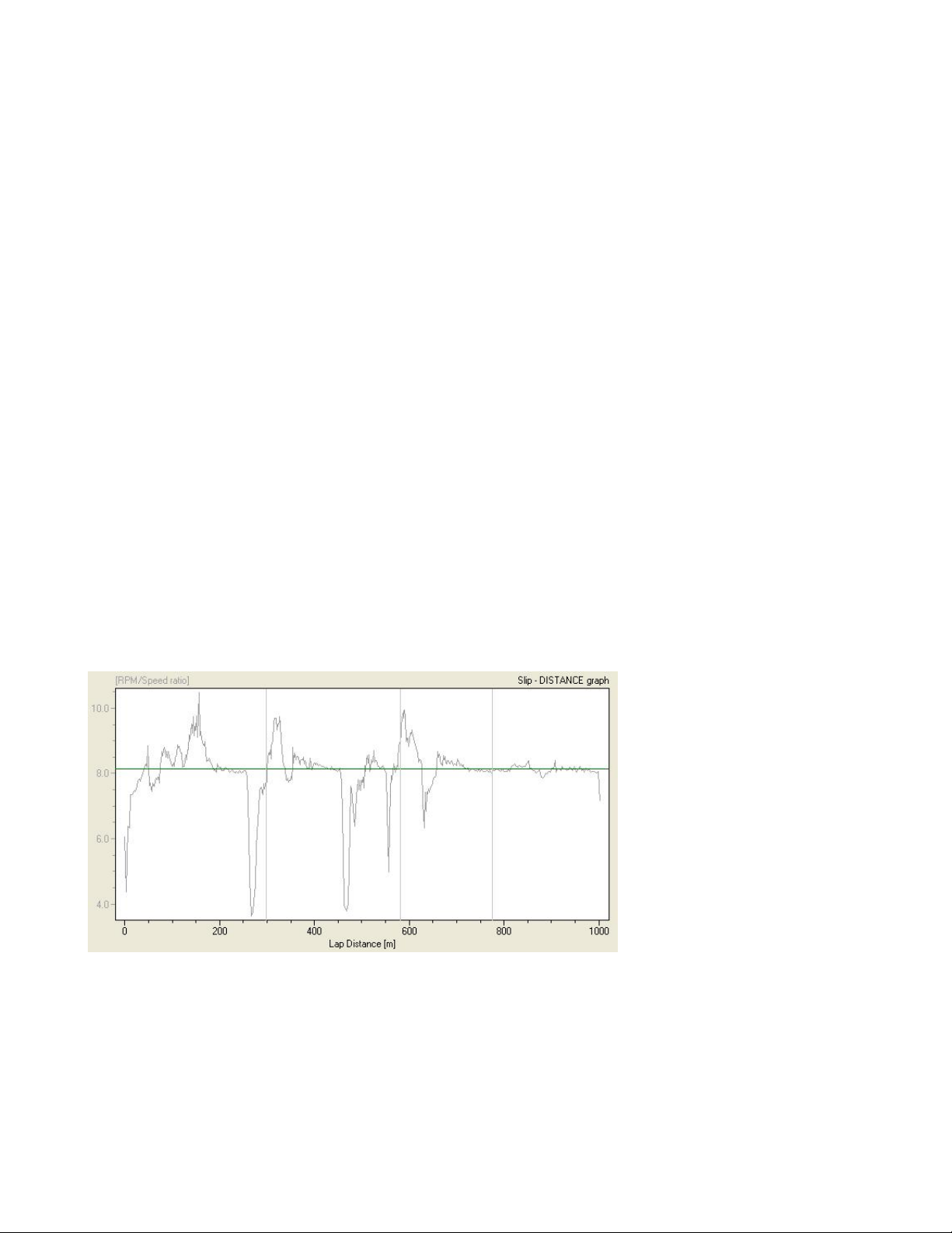
things like a slip graph showing you if the wheel is spinning or dragging and how much!
The Slip-Distance graph shows the gearing on the left axis and the lap distance in the bottom. The
gearing is the green line. Everything above the line is the rear wheel spinning and everything
below the line is the rear wheel slipping or sliding. You can use this graph to compare your driving
style from lap to lap, and learn where it is efficient with an aggressive driving style and where it
isn’t. In order to make this graph you need a precise measurement of distance, speed and RPM.
UNIPRO – The original Laptimer 15

Data stored
During race or training the Laptimer stores a lot of information . All information are stored on both
laps and splits. The Laptimer is capable of storing up to 2000 laps. However, if you use splits,
each split will count as a lap because the same information is stored. If you are driving with 5 split
points, you will get six split segments plus the total lap. Therefore the capacity is 2000 / 7 = 285
laps.
When you pass the finish line, or one of the split points, the following information is stored:
th
• Lap time or split time. This value is between 0:00:00 and 10:55:35. Resolution is 1/100
second.
th
• Lap or split length. This value is between 0 and 8900 meters. Resolution is 1/6
of the
wheel circumference.
• Min. and max. RPM. This value is between 0 and 35000 RPM. Resolution is 1 RPM. The min.
and max. RPM are based on the filtered RPM signal and it is not related to the logging. The
value is checked and stored for every pulse. That is up to 350 times per second!
• Min. and max. speed. This value is between 0.0 and 350.0 KMH. Resolution is 0.1 KMH.
• Min. and max. temp 1 and 2. This value is between 10.0 and 610.0°C. Resolution is 0.1°C.
• Min and max. temp 3. This value is between 0.0 and 800.0°C. Resolution is 0.1°C.
• Min. and max. temp 4-7. The values are between 0 and 127 degrees. Resolution is 1
degree.
• Environment temperature. The value is between 0.0°C and 51.0°C. Resolution is 0.2
degree.
• Engine number. This value is between 1 and 25.
• Tire wear counter number. This value is between 1 and 8.
• New run flag. This value is either true or false. A so-called flag is stored when you go into
the pit. This will then enable the Data Analyser or PC program to calculate the run number.
You can view all the stored data directly on your Laptimer, or you can transfer it to the Analyser,
from the Analyser you can also print the data, in order to get a better overview of the data.
Besides the data you can see directly on the Laptimer, even more detailed data are logged in the
Laptimer memory so you can transfer it to a PC for further analysis. The logging is described in
the next chapter.
UNIPRO – The original Laptimer 16

Logging
The Unipro Laptimer is a combined Laptimer and data logger. The difference between the two is
that the Laptimer is ment to give you here and now information on the track and in the pit. The
data logger stores even more information which enables you to transfer the dat a to a PC for
further analysis. This gives you the opportunity to make comparisons that are much too complex
to do just by browsing the Laptimer in the pit. The Unipro Laptimer is logging the following data:
th
• Lap time. This value is between 0:00:00 and 10:55:35. Resolution is 1/100
Stored 10 times per second.
• Distance from finish line. This value is between 0 and 8900 meters. Resolution is 1/6
the wheel circumference. Stored 10 times per second.
• Engine RPM. This value is between 0 and 35000 RPMs. Resolution is 1 RPM. Stored 10
times per second.
• Speed. This value is between 0.0 and 350.0 KMH. Resolution is 0.1 KMH. Stored 10 times
per second.
• Brake flag. This value is either true or false. Stored 10 times per second.
• Temperature 1 and 2. This value is between 10.0 and 610.0°C. Resolution is 0.1°C. Stored
1 time per second.
• Temperature 3. This value is between 0.0 and 800.0°C. Resolution is 0.1°C. Stored 2 times
per second.
second.
th
of
• Temperature 4-7. The values are between 0 and 127.0 degrees. Resolution is 0.1 degree.
Stored 1 time per second.
• Environment temperature. The value is between 0.0°C and 51.0°C. Resolution is 0.1
degree. Stored 1 time per second.
• Engine number used for the run. The value is between 1 and 25. Stored once per lap.
• Tire wear counter used for the run. The value is between 1 and 8. Stored once per lap.
• Number of temperature inputs used. The value is Temp 1-3 on/off. Stored once per lap.
• Lap number. The value is between 1 and 1023. Store once per lap.
Unipro offers a number of extra sensors, which are made with built-in processor and memory.
When using any of these extra sensors the sensors must be connected to the laptimer when you
transfer the logged data to your PC. Examples of extra sensors are G-Force, Lambda, Power
valve, steering wheel, gas pedal and brake pedal.
The logging is a background task and the logged data cannot be viewed on the Laptimer or on the
Data Analyser. The data need to be transferred to the PC Analyser program for further analysis.
In the 6002 and 6003 Laptimer there are memory enough to store 2 hours of data. In the 7002
and 7003 Laptimer there are memory enough for almost 9 hours of data. With the USB cable you
can easily transfer the data to a PC.
UNIPRO – The original Laptimer 17
 Loading...