

UniPOS Interface Module RS232/485
Instruction Manual Page 1
Revision 03-INT-02-17 of 5
INTERFACE MODULE
RS232/485
Instruction Manual 03-INT-02-17
General description
Interface Module RS232/485 is designed for implementing the communication function between
fire control panels and a personal computer or between fire control panels, connected into a network.
The module is installed in Fire Control Panels FS5100, FS5200.
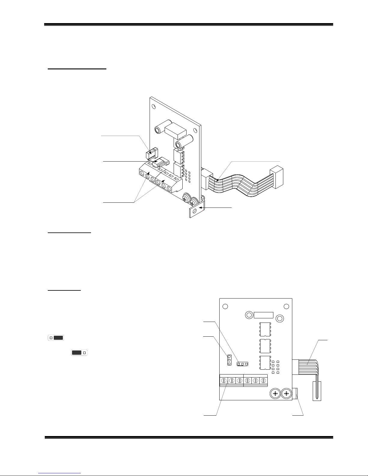
Jumper to
terminate the line
Jumper for interface
selection RS232/RS485
Terminal bus for
connecting the
interface with two/
three-wire line
Angular strap
Ribbon cable
Fig.1
Technical data
Supply voltage - (5±0.25)VDC
(the module is power supplied from the fire control panel via a ribbon cable)
Consumption - 10mA
Operational temperature range - from minus 10°C to plus 60°C
Relative humidity - (93±3)% at 40°C
Dimensions - (67х50х44) mm
Installation
1. Interface Module RS 232/485 installation steps
1.1. Unpack the module
1.2. Select the communication interface
corresponding to the desired network functionality
pos.1 (Fig.2):
- for RS232 communication – the jumper is in position
;
- for RS485 communication – the jumper is in
position .
RS232RS485
RS485 RS232
Ter.bus RS485
Interface R4.09
UniPOS
Ltd
B A
GND
Rx Tx
DTR
1
2
3
5
4
Fig.2
UniPOS Interface Module RS232/485
Instruction Manual Page 2
Revision 03-INT-02-17 of 5
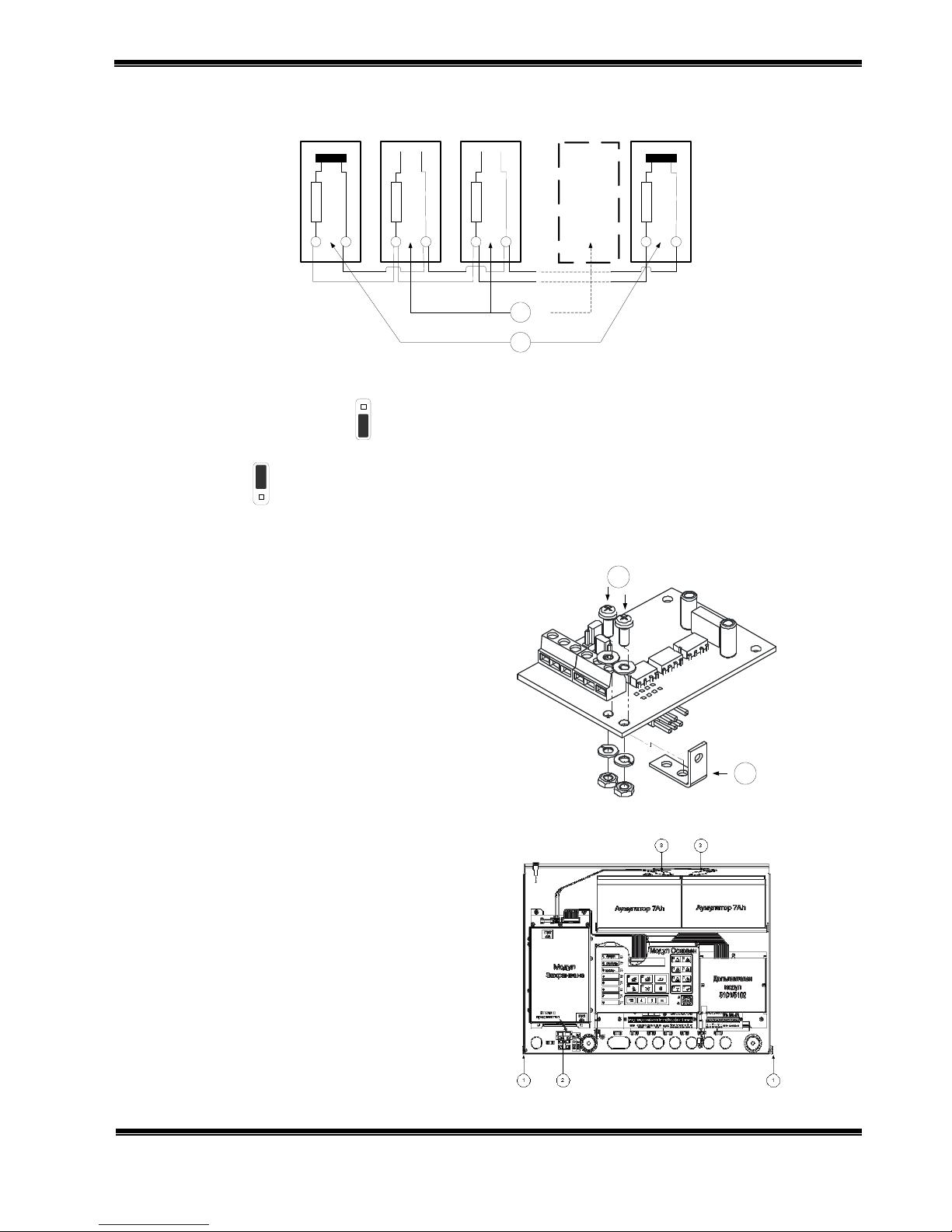
1.3. In case of RS485 communication, terminate the line resistance by means of the jumper pos.2
(Fig.2):
120 ома
120 ома
120 ома
120 ома
A A A A BB B
B
J
J J J
2
1
Remote Fire
Control Panel No.
Remote Fire
Control Panel No.
Remote Fire
Control Panel No.
Remote Fire
Control Panel No.
First device in the line
(end one for the
created network)
Last device in the
line (end one for the
created network)
Fig.3
- If the fire control panel, connected to the local network, is an end one then set the line terminating
jumper pos.1 (Fig.3) to position (On);
- If the fire control panel, connected to the local network, is not an end one then set the jumper pos. 2
(Fig.3) to position (Off).
2. Installation of Interface Module RS232/485 in Fire Control Panel FS5100
2.1 Install the angular strap pos.1 (Fig.4)
by means of the screws pos.2 (Fig.4).
2
1
Fig.4
2.2. Unscrew the two screws from the
cover of the fire control panel pos.1
(Fig.5).
2.3. Dismantle the cover
2.4. Remove the fuse Fu1 from the socket
pos.2 (Fig.5).
2.5. Disconnect the cables from the
terminals of the back up batteries pos.3.
(Fig.5).
Fig.5
UniPOS Interface Module RS232/485
Instruction Manual Page 3
Revision 03-INT-02-17 of 5
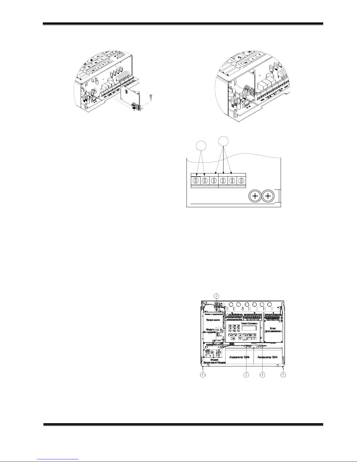
2.6. Install the module as shown on Fig.6 and fix it by means of the third screw from the set. The general
view of the Fire Control Panel FS5100 with installed module is shown on Fig.7.
Fig.6
Fig.7
2.7. Connect the local network wires Fig.8:
three-wire line to terminals Rx, Tx and GND
pos.2 (Fig.8);
wire line to terminals „А” and „В” pos.1 (Fig.8).
RS485 RS232
B A
GND
Rx Tx
DTR
1
2
Fig.8
2.8. Put back Fuse Fu1 to the socket pos.2 (Fig.5).
2.9. Connect the cables to the terminals of the back up batteries pos.3 (Fig.5).
2.10. Mount the dismantled cover of the fire control panel.
2.11. Screw in the screws of the fire control panel cover pos.1 (Fig.5).
2.12. Go to Menu System Functions, Setup, Fire Control Panel Parameters, Network Number and enter
a network number of the fire control panel. The option is to enter a four-digit network number (the
default number is 1234).
2.13. Enter the interface speed (the default speed in the fire control panel is 9600 bits/s).
2.14. Upon exit Setup menu the fire control panel enters Duty Mode.
3. Installation of Interface Module RS 232/485 in Fire Control Panel FS5200
3.1. Unscrew the two screws from the
cover of the fire control panel pos.1
(Fig.9).
3.2. Dismantle the cover
3.3. Remove the fuse Fu1 from the socket
pos.2 (Fig.9).
3.4. Disconnect the cables from the
terminals of the back up batteries pos.3
(Fig.9).
Fig.9
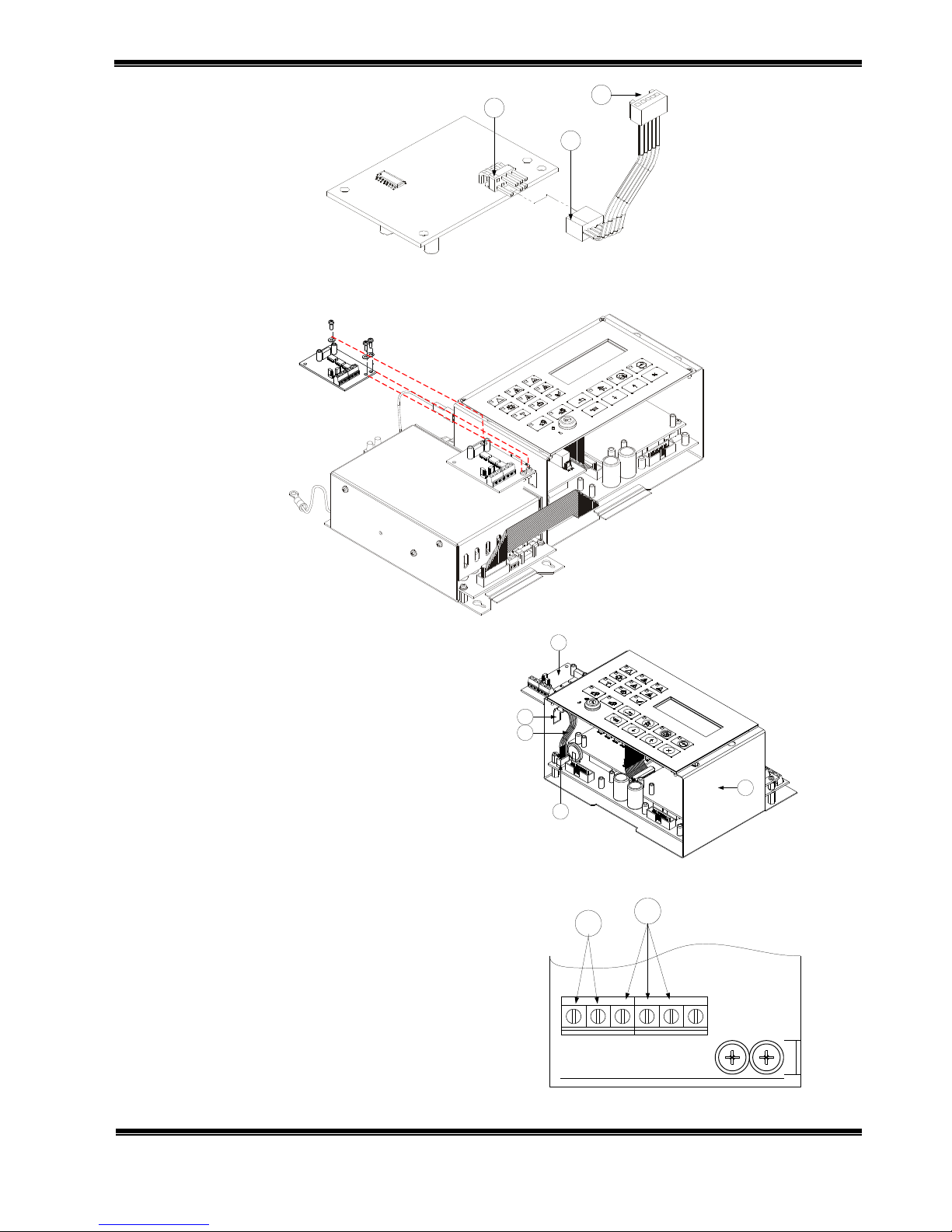
3.5. Connect the ribbon cable from the set to the module; observe the direction marks pos.1 (Fig.10)
and pos. 2 (Fig.10)
UniPOS Interface Module RS232/485
Instruction Manual Page 4
Revision 03-INT-02-17 of 5
1
2
3
Fig.10
3.6. Install the module as shown on Fig.11 and fix it by means of the three screws to the box of the Main
Module.
Fig.11
3.7. Pass the ribbon cable pos.3 (Fig.12)
through the installation hole pos.2 (Fig.12)
and connect it to the coupling pos.4 (Fig.12)
of the main module; observe the direction
pointed by the marks pos.3 (Fig.10).
1
5
3
4
2
Fig.12
3.8. Connect the local network wires Fig.8:
three-wire line to terminals Rx, Tx and GND
pos.2 (Fig.13);
wire line to terminals „А” and „В” pos.1 (Fig.13).
RS485 RS232
B A
GND
Rx Tx
DTR
1
2
Fig.13
3.9. Put back Fuse Fu1 to the socket pos.2 (Fig.9).

UniPOS Interface Module RS232/485
Instruction Manual Page 5
Revision 03-INT-02-17 of 5
3.10. Connect the cables to the terminals of the back up batteries pos.3 (Fig.9).
3.11. Mount the dismantled cover of the fire control panel.
3.12. Screw in the screws of the fire control panel cover pos.1 (Fig.9).
3.13. Go to Menu System Functions, Setup, Fire Control Panel Parameters, Network Number and enter
a network number of the fire control panel. The option is to enter a four-digit network number (the
default number is 1234).
3.14. . Enter the interface speed (the default speed in the fire control panel is 9600 bits/s).
3.15. Upon exit Setup menu the fire control panel enters Duty Mode.
Additional options
The Interface Module is a universal, galvanic separation
device for conversion from TTL levels to the electrical
parameters of RS232 and RS485 interfaces.
The communication interface is selected by means of a
jumper on the PC Board.
Figure 14 shows the layout of the PC Board coupling
signals when it is connected to the fire control panel or to the
devices with TTL.
Fig.14
Complete set
PC Board - 1 pc.
Ribbon cable - 1 pc.
Angular strap - 1 pc.
Screw 3х6 - 3 pcs.
Nut M3 - 3 pcs.
Washer Ø3 - 3 pcs.
Instruction manual - 1 pc.
Warranty
The warranty period is 24 months from the date of sale providing that the installation
requirements have been observed.
The manufacturer does not bear warranty liabilities for damages caused through
accidental mechanical damage, misuse, adaptation or modification after production.
UniPOS
47, “San Stefano” Str., 5800 Pleven, BULGARIA
phone +359 64 891111, +359 64 891 100, fax +359 64 891 110
e-mail: office_pleven@unipos-bg.com
Mladost 1, bl.79B, entr.2, ap.17, 1784 Sofia, BULGARIA
phone/fax +359 2 9744469, +359 2 9743925
e-mail: office_sofia@unipos-bg.com
www.unipos-bg.com
 Loading...