


UniPOS
Interactive Fire Control Panel
IFS7002
Instruction Manual
Revision 2.05

UniPOS Interactive Fire Control Panel IFS7002
Contents
1. Introduction...................................................................................................................................6
2. Terminology...................................................................................................................................6
3. Function.........................................................................................................................................8
4. Technical data ...............................................................................................................................8
4.1. Physical configuration.........................................................................................................................8
4.2. Fire alarm zones..................................................................................................................................8
4.3. Fire alarm loops...................................................................................................................................8
4.4. Power loop............................................................................................................................................8
4.5. Monitored outputs...............................................................................................................................9
4.6. Relay outputs for fire conditions........................................................................................................9
4.7. Relay output for fault conditions.......................................................................................................9
4.8. Performance.........................................................................................................................................9
4.9. Indications of registered events..........................................................................................................9
4.10. Power supply......................................................................................................................................9
4.10.1. Mains............................................................................................................................................................9
4.10.2. Back up batteries..........................................................................................................................................9
4.10.3. Consumption on back up batteries supply....................................................................................................9
4.10.4. Power supply to external devices...............................................................................................................10
4.11. Dimensions.......................................................................................................................................10
4.12. Weight ..............................................................................................................................................10
5. Contents of delivery.....................................................................................................................10
6. General information....................................................................................................................10
6.1. Access levels.......................................................................................................................................10
6.1.1. Access Level 1 .............................................................................................................................................10
6.1.2. Access Level 2 .............................................................................................................................................10
6.1.3. Access Level 3 .............................................................................................................................................11
6.1.4. Access Level 4 .............................................................................................................................................11
6.2. Indications and buttons for control.................................................................................................11
6.3. Zone in Coincidence Mode ...............................................................................................................13
6.4. Operation of the fire control panel..................................................................................................13
7. Duty Mode....................................................................................................................................15
7.1. Description.........................................................................................................................................15
7.2. Indication ...........................................................................................................................................15
7.2.1. LED and sound indication............................................................................................................................15
7.2.2. Text message................................................................................................................................................16
7.3. Using the keypad ...............................................................................................................................16
8. Fire condition ..............................................................................................................................16
8.1. Description.........................................................................................................................................16
8.2. Indication ...........................................................................................................................................16
8.2.1. LED and sound indication............................................................................................................................16
8.2.2. Text messages ..............................................................................................................................................17
8.3. Using the keypad ...............................................................................................................................17
Instruction Manual Page 2
Revision 2.05 Of 107

UniPOS Interactive Fire Control Panel IFS7002
9. Fault Condition ...........................................................................................................................20
9.1. Description.........................................................................................................................................20
9.2. Indication ...........................................................................................................................................21
9.2.1. LED and sound indication............................................................................................................................21
9.2.2. Text messages ..............................................................................................................................................21
9.3. Using the keypad ...............................................................................................................................22
10. Disabled component ..................................................................................................................22
10.1. Description.......................................................................................................................................22
10.2. Indication .........................................................................................................................................22
10.2.1. LED and sound indication..........................................................................................................................22
10.2.2. Text messages ............................................................................................................................................23
10.3. Using the keypad .............................................................................................................................23
11. Test Mode...................................................................................................................................23
11.1. Description.......................................................................................................................................23
11.2. Indicators .........................................................................................................................................23
11.2.1. LEDs and sound indicators ........................................................................................................................23
11.2.2. Text messages ............................................................................................................................................23
11.3. Using the keypad .............................................................................................................................24
12. Information and Control Mode.................................................................................................24
12.1. Description.......................................................................................................................................24
12.2. Menu Lists........................................................................................................................................24
12.2.1. Menu Faults...............................................................................................................................................25
12.2.2. Menu Disables ...........................................................................................................................................26
12.2.3. Menu Zones in Test....................................................................................................................................28
12.2.4. Screen Panel configuration........................................................................................................................30
12.2.5. Menu Panel parameters.............................................................................................................................30
12.2.6. Menu Loops................................................................................................................................................30
12.2.7. Menu Zones................................................................................................................................................32
12.2.8. Menu Device Status....................................................................................................................................35
12.2.9. Menu Inputs ...............................................................................................................................................38
12.2.10. Menu Archive...........................................................................................................................................39
12.3. Menu System functions....................................................................................................................46
12.3.1. Menu Disables ...........................................................................................................................................47
12.3.2. Menu Zones in Test....................................................................................................................................50
12.3.3. Function Set Clock.....................................................................................................................................51
12.3.4. Function Set Mode......................................................................................................................................52
12.3.5. Function Check LEDs and Buzzer..............................................................................................................52
12.4. Menu Set Up.....................................................................................................................................53
13. Set Up Mode...............................................................................................................................53
13.1. Description.......................................................................................................................................53
13.2. Menu Panel configuration...............................................................................................................54
13.3. Menu Panel parameters...................................................................................................................55
13.4. Menu Loops......................................................................................................................................55
13.4.1. Menu Loop parameters..............................................................................................................................55
13.4.2. Menu Device parameters..........................................................................................................................56
Instruction Manual Page 3
Revision 2.05 Of 107

UniPOS Interactive Fire Control Panel IFS7002
13.5. Menu Zones......................................................................................................................................
13.5.1. Menu Devices.............................................................................................................................................60
13.5.2. Menus Fire Phase 1 Outputs and Fire Phase 2 Outputs............................................................................65
13.5.3. Menu Zone parameters..............................................................................................................................68
13.5.4. Screen Text message ..................................................................................................................................69
59
13.6. Menu Inputs.....................................................................................................................................71
13.6.1. Screen List of addressable outputs.............................................................................................................72
13.6.2. Menu Remove addressable output.............................................................................................................72
13.6.3. Menu Add addressable output....................................................................................................................73
13.6.4. Menu Text message....................................................................................................................................74
13.7. Menu Initialization...........................................................................................................................76
13.7.1. Function Initialization................................................................................................................................77
13.7.2. Function Clean initialization......................................................................................................................78
13.7.3. Menu Readdressing....................................................................................................................................79
13.7.4. Menu Exclude devices................................................................................................................................80
13.7.5. Menu Check ...............................................................................................................................................81
13.8. Menu Checks....................................................................................................................................83
13.8.1. Menu Monitored outputs............................................................................................................................83
13.8.2. Menu Relay outputs....................................................................................................................................83
13.8.3. Menu Addressable outputs.........................................................................................................................84
13.8.4. Function Display........................................................................................................................................85
13.8.5. Menu Buttons.............................................................................................................................................85
13.9. Menu New passwords.......................................................................................................................87
13.9.1. Menu Level 2..............................................................................................................................................87
13.9.2. Function Level 3.........................................................................................................................................87
13.10. Function Default parameters.........................................................................................................88
13.11. Function Clear archive ..................................................................................................................89
14. Remote Control Mode................................................................................................................90
14.1. Description.......................................................................................................................................90
14.2. Indication .........................................................................................................................................90
14.2.1. LED and sound indication..........................................................................................................................90
14.2.2. Тext messages ............................................................................................................................................90
14.3. Keypad..............................................................................................................................................90
15. Saving the parameters...............................................................................................................
91
16. Labour protection requirements ...............................................................................................91
17. Installation and arrangements..................................................................................................
17.1. To mount the fire control panel .....................................................................................................91
17.2. Periphery devices assembly............................................................................................................91
17.2.1. Mounting periphery devices to monitored outputs.....................................................................................91
17.2.2. Mounting periphery devices to relay outputs.............................................................................................91
17.3. Connecting interface devices..........................................................................................................92
17.3.1. Global network...........................................................................................................................................92
17.3.2. Local network ............................................................................................................................................92
91
17.4. Connecting addressable fie detectors.............................................................................................92
17.5. Power supply connection ................................................................................................................93
18. Fire control panel start up ........................................................................................................
93
19. Troubleshooting.........................................................................................................................93
Instruction Manual Page 4
Revision 2.05 Of 107

UniPOS Interactive Fire Control Panel IFS7002
20. Conditions of operation, storage and transportation...............................................................96
20.1. Operation and storage.....................................................................................................................96
20.1.1. Temperature ...............................................................................................................................................96
20.1.2. Relative humidity.......................................................................................................................................96
20.2. Transportation.................................................................................................................................96
21. Warranty....................................................................................................................................96
22. Appendixes.................................................................................................................................97
Instruction Manual Page 5
Revision 2.05 Of 107

UniPOS Interactive Fire ControlPanel IFS7002
1. Introduction
Interactive Fire Control Panel IFS 7002 is an up-to-date, high reliable, multifunctional and
versatile device, providing the user with unexpected potential in the design, installation and operation
of addressable fire alarm systems.
Some of its main features and possibilities are:
− Adjustment of operating modes and parameters of each fire alarm line via built in keypad;
− User oriented menu dialogue for easy and convenient operation;
− LCD for visualization of system checkup and setup modes;
− Touch-panel contributing to the creation of a dynamic keypad;
− LEDs indication for early warning of a break down or extreme conditions;
− Energy independent archive memory saving the event type, date and time, allowing for
detailed analysis of the actions of the authorized personnel and of possible problems in the
fire protection process of the area;
− User oriented test modes allowing for a total control of the site protected;
− Built-in serial interface for connection to other fire control panels of similar or higher level;
− Built-in serial interface for connection to second level control devices, ability for connection via
telephone line and a standard modem;
− System expansion and functional modification (our goal is to constantly improve the fire alarm
equipment features), no additional cabling necessary;
− Compatible to random installation design, within the range of the available fire control panels
resources.
All these are realizable via fire control panel’s keypad and after a detailed examination of the
instructions set herewith.
2. Terminology
ACCESS LEVEL – access level to various indications and control functions.
ADDRESSABLE DEVICE – a device included in one of the fire alarm loops that has its own
address for communication with the fire control panel. An addressable device can be a fire detector
(automatic or manual call point), a conventional line-monitoring module or an input/output module.
ADDRESSABLE OUTPUT – potential or relay output of an addressable executive device included
in fire alarm loops. The executive device can be power supplied from the fire alarm loop or from the
power supply loop.
ASSOCIATED OUTPUT – addressable monitored or relay output, user programmed to react
upon Fire condition (separately upon Fire condition I and Fire condition II) via selected fire alarm
zone.
COINCIDENCE MODE– mode of operation of the fire alarm zones, that requires activation of at
least two automatic fire detectors in a zone so the fire control panel is able to enter Fire condition,
phase Fire condition stage I, in this particular zone (see section
DEVICE REMOVED – non-fatal fault condition due to removed device (addressable fire detector
of a specific zone and/or addressable executive device).
DISABLED ADDRESSABLE/MONITORED OUTPUT – the addressable/ monitored output is
switched off (the executive device can not be activated) and is not monitored for a fault condition. This
feature is user defined. The indication for a disabled addressable/monitored output is common light
indication and text messages on the LCD display.
6.3).
Instruction Manual Page 6
Revision 2.05 Of 107

UniPOS Interactive Fire ControlPanel IFS7002
DISABLED DEVICE – the addressable device (a fire detector) is switched off and is not
monitored for a fault condition. This feature is user defined. The indication for a disabled device is
common light indication and text messages on the LCD display
DISABLED ZONE – a zone that is not controlled for activated fire detectors and fault condition.
This condition is user defined. The indication for a disabled zone is common light indication and text
messages on the LCD display.
FATAL FAULT CONDITION – fault condition that prevents the fire control panel from continuing
its operation. The indication is common light indication, local sound indication and text messages on
the LCD display.
FIRE ALARM LOOP (further on it will be referred as LOOP) – automatic fire detectors and
addressable manual call points and addressable executive devices, physically connected by the
means of two-wire connection. The basic configuration of IFS 7002 includes two fire alarm loops; a
maximum of 125 devices (addressable fire detectors and/or addressable executive devices) can be
integrated into each loop.
FIRE ALARM ZONE (further on it will be referred as ZONE) – logical unification of automatic fire
detectors and addressable manual call points, physically allocated in fire alarm loops on random
principle. Interactive Fire Control Panel IFS7002 allows for formation of a maximum of 250 zones. Up
to 60 fire detectors can be integrated in each zone.
FIRE CONDITION STAGE I – phase 1 of Fire condition; upon activation of automatic fire detector
the fire control panel enters Fire condition until the specified time expires. The common and local light
indicators, local sound signaling and a text message displayed on the LCD display indicate the phase.
FIRE CONDITION STAGE II – phase 2 of Fire condition; the fire control panel enters Fire
condition stage II when: a) the time for Fire condition stage I has expired or b) upon activation of a
manual call point. The common light indicators, local sound signaling and a text message displayed
on the LCD display indicate the phase.
GROUNDS – non-fatal fault condition, due to leakage to a grounded wire.
INSPECTION TIME – period of time added to the remaining time, before the system proceeds
from Fire condition stage I to Fire condition stage II, when button is pressed. Usually, this
period of time is long enough for the authorized personnel to check up the indicated premises. The
inspection time is user defined and is specified for each zone.
INTERRUPTED LOOP OR MONITORED OUTPUT – non-fatal fault condition due to current
value in a loop or in monitored output lower than the threshold value. The user shall define the
threshold value separately for each loop.
LOCAL SOUNDER – a sounder built-in the fire control panel.
LOW BATTERY – fatal fault condition due to full discharge of the backup batteries upon
interrupted power supply.
MONITORED OUTPUT – a potential output that monitors the serviceability of the connection
wires between the fire control panel and the executive device. Follow the special diagram for
connection.
NON-FATAL FAULT CONDITION – fault condition that allows the fire control panel to continue
operation. The indication is common light indication, local sound indication and text messages on the
LCD display.
Instruction Manual Page 7
Revision 2.05 Of 107

UniPOS Interactive Fire ControlPanel IFS7002
POWER LOOP – a two-wire connection supplying power to addressable executive devices in
case their consumption exceeds the load carrying capacity of the fire alarm loops, which they have
been integrated into. IFS7002 has 1 power loop, its load carrying capacity is 1000 mA.
PROCEEDING FROM FIRE CONDITION STAGE I TO FIRE CONDITION STAGE II – the time is
user defined for each zone separately. During the phase Fire condition stage I the remaining time for
the selected fire alarm line is indicated on the LCD display. During the remaining time actions can be
taken, for example press or .
RELAY OUTPUT – a relay, potential-free switching outputs provided for controlling external
executive devices.
SHORT CIRCUIT IN A LOOP – non-fatal fault condition, entered due to registered current value
in a loop, exceeding a threshold value. The threshold value for each loop shall be user defined.
SHORT CIRCUIT IN A MONITORED OUTPUT – non-fatal fault condition, entered due to
registered current value in a monitored output, exceeding a threshold value.
SYSTEM ERROR – fatal fault condition due to a fault in system’s basic component
SYSTEM OPERATION – the fire control panel executes internal operations to set its registers.
This is visualized on the LCD display with a text message for system operations, before the user is
allowed to proceed with his work with IFS7002.
ZONE IN TEST – a zone set in Test condition by the user. The zone is reset (the fire detectors in
fire condition receive a command to clear the condition) periodically every 60 s. The events registered
in a zone in Test condition are not saved in the archive and do not trigger the associated outputs or
the light and sound signalling. The indication for a zone in Test condition is common light indication.
3. Function
Interactive Fire Control Panel IFS7002 is designed to operate with addressable automatic fire
detectors and manual call points. It controls addressable executive devices integrated into fire alarm
loops. The addressable executive devices can be power supplied from the fire alarm loop or from a
power loop. The panel has outputs provided for integration of external executive devices.
4. Technical data
4.1. Physical configuration
− 2 fire alarm loops
− 1 power loop
− 2 monitored outputs
− 2 relay outputs for fire condition
− 1 relay output for fault conditions
4.2. Fire alarm zones
− Maximum number of zones - 250
− Maximum number of fire detectors in a zone - 60
4.3. Fire alarm loops
− Maximum number of fire detectors in a loop - 125
− Connecting line - two-wire shielded
− Maximum resistance of a loop - 100Ω
− Output resistance of a loop - 20Ω
− Maximum consumption of a loop - 120mA
4.4. Power loop
− Connecting line - two-wire
− Maximum resistance of the loop - 10Ω
− Output resistance of the loop - 2Ω
− Maximum consumption of the loop - 1A
Instruction Manual Page 8
Revision 2.05 Of 107

UniPOS Interactive Fire ControlPanel IFS7002
4.5. Monitored outputs
− Type - potential
− Еlectrical characteristics - (24±5)V/100mA
4.6. Relay outputs for fire conditions
− Type - potential free, switching,
− Electrical characteristics - 3A/125VAC; 3A/30VDC
4.7. Relay output for fault conditions
− Type - potential free, switching
− Electrical characteristics - 3A/125VAC; 3A/30VDC
4.8. Performance
− Control over fire alarm loops and monitored outputs for fault conditions (short circuit
and interruption) and automatic reset
− Detection of removed devices in the loops and automatic reset
− Ability to set the zones in Coincidence Mode
− Two phases of Fire condition, programmable time for Fire condition stage I,
separately for each zone
− Option to prolong the time period for Fire condition stage I with programmable
inspection period, specified for each zone
− Built-in sounder for fire condition – one tonal, discontinuous, can be switched off
− Built-in sounder for fault condition – one tonal, discontinuous, can be switched off
− Built-in real time clock
− Set of test modes and options for adjustment:
♦ Setting the clock;
♦ Check ups on light and sound indications;
♦ Test of fire alarm zones;
♦ Adjustment of outputs and integrated external devices;
♦ Programming of parameters and modes of operation;
♦ Remote programming of the parameters from distant operator control point;
− Energy independent archive of registered events with the events type, date and hour
– up to 1023 events;
− Interfaces for communication with external devices - CAN 2.0B and RS-232
(directly or via modem).
4.9. Indications of registered events
− Light indication - LED
− Text messages - LCD display,
320 х 240 points, backlit
− Sound signaling - built-in sounder
4.10. Power supply
4.10.1. Mains
− voltage - 220/230V
− frequency - 50Hz
4.10.2. Back up batteries
− battery type - lead, gel electrolyte
− number of batteries - 2 pcs
− connection - serial connection
− nominal voltage of the back up battery - 24V
− nominal capacity C
- 18Ah
20
− extreme discharge voltage - 21V
− charge voltage - 28,2V
4.10.3. Consumption on back up batteries supply
− at 24V - < 250mA
− at 26V - < 240mA
Instruction Manual Page 9
Revision 2.05 Of 107

UniPOS Interactive Fire ControlPanel IFS7002
4.10.4. Power supply to external devices
− Voltage - (24±5)V
− Maximum current value (including current
of monitored outputs and power loop) - 1,5А
4.11. Dimensions
− Overall dimensions - 480x445x100mm
4.12. Weight
− Weight (batteries not included) - 7,1kg
5. Contents of delivery
− Fire control panel IFS7002 - 1 pc
− Resistors 5,6kΩ/ 0,25W - 2 pcs
− Jumper for the backup batteries - 1 pc
− Fuse 4A - 2 pcs
− Instruction manual - 1 pc
− Instructions for authorized staff - 1 pc
− Packing - 1 pc
6. General information
6.1. Access levels
4 levels of access to the variable indications and control functions of IFS7002 are available.
6.1.1. Access Level 1
All persons who would presumably find out and react to alarm upon fault condition or fire
condition have access to level 1.
The following actions are accessible:
− Displaying suppressed messages for Fire condition, Fault condition, Disabled
components and Zone in test (see sections
− Entering inspection time period (see section
− Forced proceeding from phase Fire condition stage I to phase Fire condition stage II (see
section
− Suppressing the local sounder (see sections
− Displaying program data for the fire control panel (see sections
12.2.9);
− Displaying the status of the addressable devices in the loops (see section
− Displaying the archive (see section
All light indicators are visible.
6.1.2. Access Level 2
The personnel in charge of the fire protection have access to level 2; they shall be authorized and
trained to operate the fire control panel in the following conditions:
− Duty Mode;
− Fire condition;
− Fault condition;
− Disabled component;
− Information and adjustment.
To enter Access level 2 use your password.
The following features of the fire control panel are accessible:
− All features accessible at Level 1;
− Switching off the outputs, activated upon fire condition (see section
− Exit of Fire condition (see section
− System functions of the fire control panel (see section
8);
12.2.10).
8);
8, 12.2.1, 12.2.2 and 12.2.3);
8.3.1);
8 and 9);
12.2.4 to 12.2.7 and
12.2.8);
8);
12.3).
Instruction Manual Page 10
Revision 2.05 Of 107

UniPOS Interactive Fire ControlPanel IFS7002
6.1.3. Access Level 3
Accessible for personnel trained and authorized for:
− Reconfiguration of specific data – of the protected site or of the fire control panel – saved
in the memory;
− Maintenance of the fire control panel.
This level has two sublevels of access - 3A and 3B.
Level 3, sublevel 3A, is accessed through a password entered at Access level 2. At this sublevel
the functions for reconfiguration of specific data for the protected site or the fire control panel are
accessible (see section
13).
Level 3, sublevel 3B is accessed when the fire control panel is opened. The following features are
accessible:
− Replacing a burnt fuse;
− Connecting fire alarm loops and executive devices.
6.1.4. Access Level 4
Accessible for personnel trained and authorized by the Producer to repair the fire control panel
and to modify the software. Special means are required to enter this level.
6.2. Indications and buttons for control
Table 1 gives detail description of the indications for each status, Table 2 presents the basic
means for control. Appendix 1 shows the front panel of IFS7002.
Conditions of the fire control panel Indication
All conditions The fire control panel is power supplied
Fire condition
Fault condition All faults except for Battery Low
Fault condition – System error
Fault condition Fault in mains supply
Disabled component Disabled zone, addressable device or monitored
output
Test condition
Fire condition
Table 1
Indicator Power supply –
continuous green light
Common indicator Fire condition –
flashing red light
Common indicator Fault condition
– flashing yellow light
Indicator System error - continuous
yellow light
Indicator Fault in mains supply -
flashing yellow light
Indicator Disabled component continuous yellow light
Indicator Test –
continuous yellow light
Local sounder – discontinuous signal: 0.5 s
sound, followed by 0.5s break
Fault condition - All faults except for Battery Low
Fault condition Low battery
Local sounder – discontinuous signal: 1 s
sound, followed by 1 s break
Local sounder – discontinuous signal: 1 s
sound, followed by 3 s break
Instruction Manual Page 11
Revision 2.05 Of 107

UniPOS Interactive Fire ControlPanel IFS7002
Table 2
Means of control
Button Reset Fire
Button Outputs
(no suppressed
outputs) or
(suppressed
outputs)
Button Inspection
Button Stop Alarm Fire condition and
Condition of the fire
control panel
Fire condition Level 2 To exit the Fire condition
Fire condition, phase
Fire condition stage I
Fire condition, phase
Fire condition stage I
Fire condition, phase
Fire condition stage II
Fire condition, phase
Fire condition stage I
Fault condition (with
the exception of Fatal
Fault Condition)
Access
level
Level 1
Level 2
Level 2
Levels
1 and 2
Levels
1 and 2
Operation
To force transition from Fire condition stage
I to Fire condition stage II
- upon activated outputs for fire condition –
to suppress the outputs;
- if no outputs for fire condition are
activated - to force transition to phase Fire
condition stage II
- upon activated outputs for fire condition –
to suppress the outputs
- if no outputs for fire condition are
activated – to activate all suppressed
outputs
To add time period for inspection
To suppress the local sounder
Button Menu
Button Enter
Button Down
Button Up
Duty mode, Fire
condition, Fault
condition (with the
exception of Fatal
Fault Condition) Test
mode and Disabled
component
Information and
Control Mode
Information and
Control Mode
SetUp Mode Level 3А
Information and
Control Mode
SetUp Mode Level 3А
Information and
Control Mode
SetUp Mode Level 3А
Level 1 To enter Information and Control mode
Level 1 To enter a selected menu
Level 2
Levels
1 and 2
Levels
1 and 2
- To enter a selected menu;
- To execute a selected command;
- To save a modified parameter
To display the next element of the menu
To display the previous element of the
menu
Button Exit
Instruction Manual Page 12
Revision 2.05 Of 107
Information and
Control Mode
SetUp Mode Level 3А To exit SetUp Mode and reset the system
Levels
1 and 2
To exit Information and Control Mode

UniPOS Interactive Fire ControlPanel IFS7002
Means of control
Button Cancel
Button Change
Button Move down
Button Move up
Button Page down
Condition of the fire
control panel
Information and
Control Mode
SetUp Mode Level 3А
Information and
Control Mode
SetUp Mode Level 3А
Fire condition and
Information and
Control Mode
SetUp Mode Level 3А
Fire condition and
Information and
Control Mode
SetUp Mode Level 3А
Information and
Control Mode
Access
level
Levels
1 and 2
Levels
1 and 2
Levels
1 and 2
Levels
1 and 2
Level 1
Operation
- To exit a function without saving changes
in the parameter; the command will not be
executed;
- To exit the current menu and to move to
an upper hierarchy menu
To change an element to its next
permissible
Next element (if any are available) from the
left window
Previous element (if any are available) from
the left window
Next page from the left window
Button Page up
Button To the right
Button To the left
Button Clear
С
Buttons with digits,
characters and
symbols
Information and
Control Mode
Information and
Control Mode
SetUp Mode Level 3А To move the cursor one position to the right
Information and
Control Mode
SetUp Mode Level 3А To move the cursor one position to the left
Information and
Control Mode
SetUp Mode Level 3А
Information and
Control Mode
SetUp Mode Level 3А
Level 1
Levels
1 and 2
Levels
1 and 2
Levels
1 and 2
Levels
1 and 2
Previous page from the left window
- To move the cursor one position to the
right;
- Next element (if any are available) from
the left window
- To move the cursor one position to the
left;
- Next element (if any are available) from
the left window
To delete a character pointed by the cursor
(if no character is pointed, the first
character to the left of the cursor will be
deleted)
To insert a character/symbol to the left of
the cursor
6.3. Zone in Coincidence Mode
Coincidence Mode allows for enhanced certainty that a zone has entered Fire condition, phase
Fire condition stage I. The mode requires that at least two fire detectors from this zone shall be
activated to trigger Fire condition, phase Fire condition stage I in the fire control panel.
Instruction Manual Page 13
Revision 2.05 Of 107

UniPOS Interactive Fire ControlPanel IFS7002
The Coincidence Mode is not applicable to manual call points. If a manual call point, included in a
zone set to Coincidence Mode, responds, the fire control panel enters Fire condition, phase Fire
condition stage II in this particular zone.
Upon activation of an automatic fire detector from a zone set to Coincidence Mode, but the fire
control panel has not entered Fire condition in this zone, then:
− If no other automatic fire detector is activated, the zone enters Pre-Fire condition;
− If another automatic fire detector is activated, i.e. the zone is in Pre-Fire condition, then the
fire control panel enters Fire condition, phase Fire condition stage I, in this particular zone.
Exit from Pre-Fire condition in a zone is done automatically only:
− Upon activation of a second automatic fire detector in the zone within 60 s from the Pre-Fire
condition (the fire control panel enters Fire condition, phase Fire condition stage I, in this
particular zone);
− Upon activation of a manual call point in the zone, within 60 s from the Pre-Fire condition (the
fire control panel enters Fire condition, phase Fire condition stage II, in this particular zone)
− Where the 60 s of Pre-Fire condition expire and neither of the above mentioned two conditions
is carried out (the first activated fire detector then receives a command to reset the fire
condition).
To set a zone in Coincidence Mode you need to appoint the parameter Coincidence Mode for this
zone (see section
While using the Coincidence Mode in a zone, we recommend you to include just one group of
automatic fire detectors (minimum 2 fire detectors) in this zone, allocated in one and the same room,
so upon activation of any two fire detectors you obtain a firm indication for fire in the room.
13.5.3).
6.4. Operation of the fire control panel
When IFS7002 is switched on, reset of the system devices and initialization of the addressable
devices integrated in the loops are being done – addressable devices parameters (address,
identification number, type and class) are being verified against these saved in the energy
independent memory of the fire control panel. A text message -System operations - is displayed on
the LCD.
Upon completion of the system operations the fire control panel enters operation mode – it
monitors the addressable devices (automatic fire detectors, manual call points and executive devices)
by consecutively scanning their condition. Simultaneously, a constant control over the loops, the
monitored outputs and the voltage for fault conditions is being carried out.
The fire control panel IFS7002 operates in eight basic modes: Duty Mode, Fire Condition, Fault
Condition, Disabled Component Mode, Test Mode, Information and Control Mode, SetUp Mode and
Remote Control Mode.
Duty Mode, SetUp Mode and Remote Control Mode can not be combined with another mode:
− the fire control panel enters Duty Mode after all other conditions are exited;
− when the fire control panel enters SetUp Mode or Remote Control Mode it exits all other
conditions.
When the fire control panel is in Fire condition or in Fault condition or in a combination of one of
these, the lighting of the display is constantly on, until you press button Stop alarm (with the
exception of these fault conditions – Battery low, discharged batteries due to interruption of mains
supply, and Fault in mains supply). Upon Battery low the lighting of the display is constantly off. In all
other cases the lighting is extinguished 3 min after the last pressing of any button on the display.
Up to 250 fire alarm zones can be formed in IFS7002. Except for these zones the fire control
panel supports two additional zones:
− Service zone (Zone 0) – here addressable devices which location in the loop can not be
detected synonymously are integrated;
− Zone 255 – here addressable devices not included or that can not be included in a fire alarm
zone (addressable output and input devices) are integrated.
When a removed addressable device is replaced in a loop, the fire control panel runs initialization
once again and verifies its parameters (previous address, identification number, type and class)
against these saved in the energy independent memory. While this operation is being executed, the
text message ReInitialization appears on the display.
Instruction Manual Page 14
Revision 2.05 Of 107

UniPOS Interactive Fire ControlPanel IFS7002
Depending on the result of the verification, the fire control panel would execute the following
operations:
a) if the fire control panel is able to synonymously detect the location of a device in a loop and to
verify its parameters against these saved in the energy independent memory:
♦ the device is placed in service with its previous address in the loop;
♦ the fault Removed device is cleared;
b) if the fire control panel is able to synonymously detect the location of a device in a loop, but
the device’s parameters do not conform with these saved in the energy independent memory:
♦ the device is placed in service with an address, corresponding to device’s location in
the loop;
♦ a fault condition due to incompliance with identification number, type or class is
added;
♦ the device is included in the Service zone;
c) if the fire control panel is not able to synonymously detect the location of a device in a loop
(two or more serial devices forming an area are removed, but only some replaced):
♦ the device is placed in service with the first available address from the corresponding
area in the loop;
♦ a fault is added, Device not initialized;
♦ the device is included in the Service zone.
When the last device for Removed devices area is placed, the fire control panel will
synonymously detect their location. For the last placed device the fire control panel will run operations
a) or b). For previously placed devices the fire control panel will run the following operations:
d) if the fire control panel detects compliance of parameters with these saved in the energy
independent memory:
♦ the device is placed in service with its previous address in the loop;
♦ the faults Removed device and Device not initialized are cleared;
♦ the device is excluded from the Service zone;
e) if the fire control panel detects incompliance of parameters with these saved in the energy
independent memory:
♦ the device is placed in service with an address, corresponding to device’s location in
the loop;
♦ a fault condition due to incompliance with identification number, type or class is
added;
♦ the device remains in the Service zone.
In cases b), c) and e) the following actions can be taken:
− if any devices seemed to be involuntarily exchanged, they shall be placed on the proper
locations;
− the device can be excluded from the Service zone by using the
section
− to save the new loop configuration by using the
section
When a new addressable device (exceeding the number of addressable devices in the loop), the
fire control panel sets a temporary address for this device (the text message Reinitialization appears
on the lower end of the display) but ignores the device during further operation. To include the device
in the loop configuration you need to start the
13.7.3) and setting the proper address;
Function Clean initialization (see
13.7.2).
Function Clean initialization (see section 13.7.2).
Menu Readdressing (see
7. Duty Mode
7.1. Description
The fire control panel is in Duty Mode, when it is not in any other of the rest 7 possible conditions.
7.2. Indication
7.2.1. LED and sound indication
In Duty Mode the green LED indicator is activated (Power supply). The local sounder is off.
Instruction Manual Page 15
Revision 2.05 Of 107

UniPOS Interactive Fire ControlPanel IFS7002
M
7.2.2. Text message
The display shows the logo of
the company-producer, information
on the current local time and the
mode of operation of the fire control
panel (DAY or NIGHT):
ode:DAY
FIRE CONTROL PANEL IFS7002
UniPOS Ltd
Thu 03 Feb 2005
9:42:23
7.3. Using the keypad
The only accessible button in Duty Mode is (Menu). Press it and the fire control panel
enters Information and Control Mode.
8. Fire condition
8.1. Description
The fire control panel enters Fire Condition after a fire detector has been activated in one of the
fire alarm zones. In Mode:DAY the condition has two phases – Fire condition stage I and Fire
condition stage II. The time period for Fire condition stage I is limited and is user programmable,
separately for each zone (up to 255 seconds). The period can be prolonged with the Inspection time
(see section
8.3.1). When Fire condition stage I in this particular zone expires, the fire control panel
enters Fire condition stage II in the same zone.
The fire control panel enters Fire condition stage I upon activation of an automatic fire detector
and Fire condition stage II - upon activation of a manual call point.
In Night Mode the phase Fire condition stage I is ignored. The fire control panel enters Fire
condition, phase Fire condition stage II upon activation of a manual call point or of an automatic fire
detector. The fire control panel can be in Fire Condition in one or more zones. In the second case,
when in Mode:DAY, the fire control panel can be in phase Fire condition stage I in part of the zones,
and in phase Fire condition stage II in the rest of the zones.
To exit this condition press button at Access level 2 (see section
8.3.4).
8.2. Indication
8.2.1. LED and sound indication
In this condition the common light indicator illuminates in red flashing light (Fire condition).
The local sounder produces discontinuous signal (0,5s sound, 0,5s break), if the device has not
been suppressed by button (Stop Alarm).
Instruction Manual Page 16
Revision 2.05 Of 107

UniPOS Interactive Fire ControlPanel IFS7002
M
1
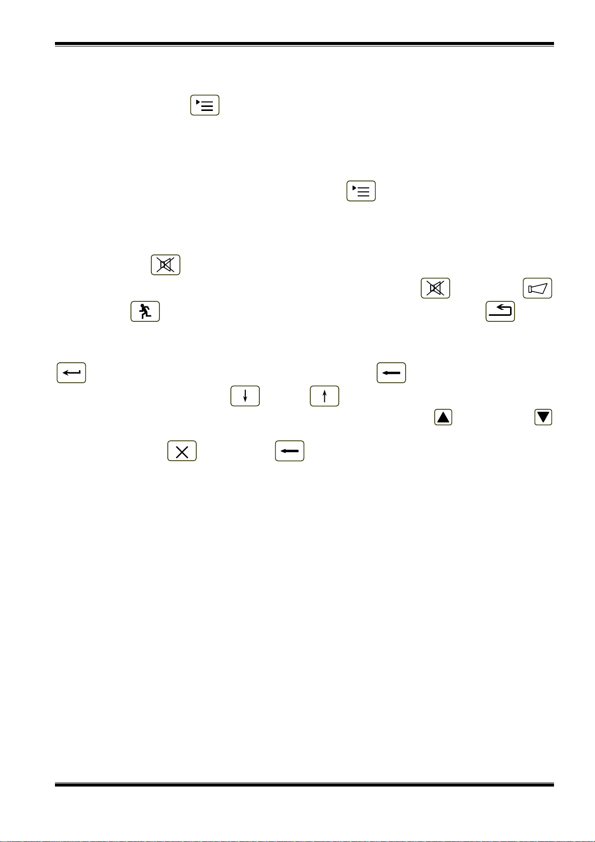
8.2.2. Text messages
Information on zones for which
the fire control panel has detected
Fire condition is displayed:
For this condition the display is
divided into three panels.
The first panel (the upper one)
displays information on zones in fire
condition. A flashing heading with the
text FIRE and the total number of
zones in fire condition appear. The
panel is subdivided into two text
fields, each providing two lines. The
FIRE CONDITION ZONES IN FIRE: 3
1 Phase 2 Zone 001
Zone 001
3 Phase 1 Zone 002
Zone 002
Time Fire Phase2: 120
Devices in Fire TOTAL NUMBER: 4
1 Loop 01 Zone 001 Addr 001
Point 1.001
2 Loop 02 Zone 003 Addr 001
Point 2.001
4 Loop 01 Zone 002 Addr 002
Point 1.002
Faults Total: 00000
Disables Total: 000
Failed Outputs: 00000
Disabled Outputs: 000
first line displays information on the
first zone in fire condition, the second
line provides information on the last
zone in fire condition.
ode:DAY
1:11:08 Thu 03 Feb 2005
The first line of each field provides information on the type of the fire condition:
− the sequence number of the indicated fire condition;
− the phase of Fire condition detected by the fire control panel in this particular zone;
− the zone number;
− the remaining time in seconds before the fire control panel proceeds to phase Fire condition
stage II (indicated only in Fire condition stage I).
The second line of each field displays a text message for the corresponding zone. If the fire
control panel has entered Fire condition in more than two zones, the rest of the text messages for fire
condition are suppressed. They can be displayed in the upper field by pressing the buttons on the
right side (see section
8.3.5.1).
The second panel (the middle one) provides information on devices in fire condition. In the head
part is displayed the total number of devices in fire condition. The panel itself is subdivided into three
text fields, each providing two lines. The upper two-line field displays information on the first device
that has detected fire condition; the middle two-line field displays information on the second device in
fire condition, the bottom two-line field – information on the last device.
The first line of each field provides information on the device:
− the sequence number of the device in fire condition;
− the fire alarm loop where the device is integrated into;
− the zone number;
− the device address in the fire alarm loop.
The second line of each field displays text messages relevant to this particular device.
If more than three devices are activated due to fire condition, the rest of the messages are
suppressed. However, they can be displayed in the upper fields, by pressing the buttons on the right
side (see section
8.3.5.2).
The third panel (the bottom one) displays information on the numbers of faults and disables –
total number and for the outputs (monitored outputs and addressable output devices).
8.3. Using the keypad
8.3.1. Button (Inspection)
The button appears on the display when the fire control panel enters phase Fire condition stage I
in a new zone; it is extinguished if pressed or if all zones in Fire condition proceed to phase Fire
condition stage II.
When you press the Inspection button, the remaining time for the zones in Fire condition stage I
after which they proceed to Fire condition stage II, is prolonged with user programmed inspection time
for each particular zone. The operation can be performed only once for each zone in Fire condition
Instruction Manual Page 17
Revision 2.05 Of 107

UniPOS Interactive Fire ControlPanel IFS7002
M
9:4
stage I, i.e. it is executed for zones where the remaining time has not already been prolonged with
inspection time.
8.3.2. Button (Stop Alarm)
The button appears on the display when the fire control panel enters Fire condition in a new zone
or upon registration of a new fault condition; it is extinguished if pressed or if the local sound signaling
is suspended (fault conditions suspended and/or the fire control panel exits Fire condition).
Press it to turn off the local sounder.
Button’s operation does not effect and is not cancelled by the following events:
− When the fire control panel enters Fire condition in a new zone or proceeds from Fire
condition stage I to Fire condition stage II, the local sounder is activated for Fire condition
only.
− A new fault condition will trigger the local sounder for Fault condition only.
8.3.3. Button (Outputs)
The button is displayed when the fire control panel is in Fire condition.
Its operation depends on the current access level and on the status of the fire control panel:
− At Access Level 1 and in the presence of zones in Fire condition stage I, press the button to:
♦ force transition to Fire condition stage II – where no outputs for fire condition responded;
♦ Suppress activated outputs for fire condition – where outputs for fire condition responded.
− At Access Level 2 and in absence of zones in Fire condition stage I (i.e. the fire control panel
is in phase Fire condition stage II only), press the button to:
♦ Suppress activated outputs for fire condition – where outputs for fire condition responded;
♦ Activate suppressed outputs - where no outputs for fire condition responded.
If outputs for fire condition are suppressed, the button appears with the following graphics .
8.3.4. Button (Reset Fire)
The button appears on the display when the fire control panel is in Fire condition and is provided
to force the exit from Fire condition, at Access Level 2.
8.3.4.1. Access Level 1
Press the button at Access Level
1 to display a screen provided for
password entry:
To enter a password use the
buttons with digits – press a digit and
it appears on the place of the
cursor„_”, and the previous text and
the cursor itself move one position to
the right. Move the cursor to the left
FIRE CONDITION ZONES IN FIRE: 2
1 Phase 1 Zone 001
Zone 001
2 Phase 1 Zone 003
Zone 003
Time Fire Phase2: 068
Time Fire Pase2: 080
PASSWORD Reset Fire
Enter Password: _
or to the right, using buttons and
. Button will delete:
С
1 2
0
3 4 5
6 7
8
9 С
− Any digit under the cursor;
− Or, if there is no digit under
the cursor, then will be
ode:DAY
8:32 Mon 11Apr 2005
deleted the first digit to the
left.
The length of the password can be 10 symbols maximum. If you press a digit button when the 10symbol password is entered, the digit will not be inserted.
Instruction Manual Page 18
Revision 2.05 Of 107

UniPOS Interactive Fire ControlPanel IFS7002
The operation of button is:
− If a wrong password is entered – the entered digits will be deleted and the cursor will appear
over the password’s first position;
− If one of the 10 passwords for Access Level 2 or the password for Access Level 3 is entered:
♦ The fire control panel will exit the Fire condition;
♦ The fire control panel will exit Information and Control Mode if it was in a combination
of Fire condition and Information and Control Mode.
To exit the screen press buttons (Exit) or (Cancel). Then, if the fire control panel had
been in a combination of Fire condition and Information and Control Mode, it would exit Information
and Control Mode.
8.3.4.2. Access Level 2
At Access Level 2 press the button and the fire control panel will exit Fire condition and
Information and Control Mode.
8.3.5. Buttons (Move down) and (Move up)
8.3.5.1. Panel for zones in fire condition
Where suppressed messages for zones in fire condition are available they can be displayed in the
text fields of the first (upper) panel on the LCD display, by the means of buttons and situated
in the panel’s right section.
Button appears on the display where a message for a zone in Fire condition following the
message in the first text field is suppressed. Press the button to display it. When the last suppressed
text message for a zone in Fire condition is reached, the button disappears.
Button appears on the display where a message for a zone in Fire condition preceding the
message in the first text field is suppressed. Press the button to display it. When the first suppressed
text message for a zone in Fire condition is reached, the button disappears.
If a suppressed message for a zone in Fire condition is displayed, 20 s after the last button is
pressed, the message for the first zone in fire condition will be automatically restored.
8.3.5.2. Panel for devices in Fire condition
Where suppressed messages for devices in Fire condition are available, they are displayed in the
two text fields of the second (middle) panel, by the meansр of buttons and situated in the
right part of the panel.
Button is activated if the numbers of the messages in the second and the third field are not
consecutive. When you press the button you will display the consecutive messages for devices in
Fire condition, in the first and second text fields.
Button is activated if the number of the message in the first text field is higher than 1. When
you press the button you will display the previous messages for devices in Fire condition, in the
first and second text fields of the middle panel.
8.3.6. Button (Menu)
Press the button to enter Information and Control Mode; the mode uses the middle and the
bottom panel of the screen for Fire condition.
Instruction Manual Page 19
Revision 2.05 Of 107

UniPOS Interactive Fire ControlPanel IFS7002
8.3.7. Button (Exit)
When Fire condition is in combination with Information and Control Mode, press the button and
the fire control panel exits Information and Control Mode and on the display appear all three panels of
the screen for Fire condition.
9. Fault Condition
9.1. Description
The fire control panel enters Fault Condition when any of the events below have been registered:
− Fatal system error;
− Battery low – backup batteries discharged due to interruption of mains supply;
− Fault in a processor programme;
− Fault in a module;
− Fault in the real time clock;
− Fault in the external memory;
− Fault in a loop – a short circuit or a break;
− Loop not initialized;
− Higher number of devices in the fire alarm loop;
− Fault in a zone – upon detection of fault condition in a device, integrated in the zone;
− Removed device;
− Fault condition in a device;
− Activated isolator of a device;
− Activated isolator at the Power loop of a device;
− Contaminated fire detector (for optical detectors|;
− Communication error
− Device not initialized (detected new device in a loop);
− Exchanged devices;
− Different identification number of a device,
− Different device type;
− Different device class;
− Fault in a monitored output – short circuit or break;
− Fault in the mains supply;
− Fault in the backup batteries supply;
− Short circuited ground wire;
− Fault in the positive supply of the loops;
− Fault in the negative supply of the loops;
− Fault in external devices supply.
Where a fatal system error occurs, the main processor can not continue operation and the fire
control panel does not control loops, outputs and other periphery devices. To exit fatal system error
you have to cut off the mains supply and to repair the control panel.
Battery Low is a fatal non-system error; zones and outputs are not being services. The fire control
panel enters a special condition:
− A discontinuous sound signal is produced - 1s sound, 3s break for at least 1 hour;
− Only the green LED indicator is illuminated (Power supply).
− The lighting of the display is extinguished;
− Only the supply voltages are controlled.
The condition is exited automatically 20 s after the mains supply is restored.
All other fault conditions are not fatal and switch off some periphery devices. The condition is
exited automatically 20 s after the fault is suspended.
Upon fault condition Short circuit to ground wire where an element of a monitored output is short
circuited, fault condition in the monitored output (break) is also developed.
Fault condition is indicated by LEDs indicators and a text message on the LCD display.
Instruction Manual Page 20
Revision 2.05 Of 107

UniPOS Interactive Fire ControlPanel IFS7002
9.2. Indication
9.2.1. LED and sound indication
Where fatal system errors occur the indicators (Fault condition) and (System error)
illuminate in continuous yellow light. The local sounder produces continuous signal.
Upon Low battery fault condition no LED indicator is illuminated. The local sounder produces
discontinuous signal (1 s sound, followed by 3 s break). The lighting of the LCD display is off.
All other fault conditions are designated by indicator (Fault condition), flashing in yellow.
Depending on the specific fault, the following indicators are illuminated too:
− Upon System error - indicator (System error) is flashing in yellow;
− Upon Fault in mains supply - indicator (Fault in mains supply) is flashing in yellow.
The local sounder produces discontinuous signal (1s sound, 1s break), if not previously suppressed
by (Stop Alarm) button.
9.2.2. Text messages
Upon fatal system errors the
following information screen is
displayed (the first line of the text
messages is information intended for
the service staff):
The screen suppresses all other
text indications and can not be
suppressed.
Fault condition
Restart please
Upon Battery Low condition - full
discharge of the backup batteries
due to interrupted power supply – the
following information screen appears:
The screen suppresses all other
text indications, with the exception of
System error message, and can not
be suppressed.
Battery low
Instruction Manual Page 21
Revision 2.05 Of 107

UniPOS Interactive Fire ControlPanel IFS7002
M
For all other fault conditions a
table, containing information on the
number of fault events and the
number of disabled devices is
displayed. The first line of the tables’
left column displays the total number
FIRE CONTROL PANEL IFS7002
UniPOS
Thu 03 Feb 2005
11:43:13
of fault conditions; the first line of the
table’s right column displays only the
number of faults in outputs
(monitored outputs and addressable
output devices):
Faults Total: 00001
Disables Total: 000
Failed Outputs: 00000
Disabled Outputs: 000
To display the text message for
each fault condition, enter
Information and Control Mode (see
section
12.2.1).
ode:DAY
9.3. Using the keypad
None of the buttons is active upon fatal fault condition. For all other fault condition 2 buttons are
being supported. Where the fire control panel operates in combination of other conditions, their
buttons are active too.
9.3.1. Button (Stop Alarm)
The button appears on the LCD display where the fire control panel enters fire condition in a new
zone or a new fault condition occurs; it disappears if pressed or if the sound signaling is suspended
(fault conditions suspended and/or fire control panel exited fire condition)
Press the button to switch the local sounder off.
The button does not affect and is not influenced by the following events:
− Fire condition in new zone or transition from phase Fire condition stage I to Fire condition
stage II will trigger the local sounder and a signal for fire condition only will be produced;
− New fault condition will trigger the local sounder and a signal for fault condition only will be
produced.
9.3.2. Button (Menu)
Press the button to enter Information and Control Mode.
10. Disabled component
10.1. Description
The fire control panel enters Disabled component after a manual operation, disabling a specific
component – a fire alarm zone, addressable device or monitored output. The condition is handled via
Information and Control screens (see section
12.3.1). A disabled zone is not monitored for activated
fire detectors or fault condition. A disabled addressable device is not activated (if it is an executive
device) and is not monitored for activation (if it is a fire detector) or fault condition. A disabled
monitored output is switched off (the executive device is not able to respond) and is not monitored for
fault condition.
Where disabled zones, disabled addressable devices or disabled monitored outputs are available,
the LED indication illuminates and the relevant message is displayed
10.2. Indication
10.2.1. LED and sound indication
The condition is indicated by the Common indicator (Disabled component) illuminated in
continuous yellow light.
No sound signaling is supported for Disabled component condition.
Instruction Manual Page 22
Revision 2.05 Of 107

UniPOS Interactive Fire ControlPanel IFS7002
M
10.2.2. Text messages
If a disabled component is
available, a table giving information
on the total number of disabled
devices and faults appears on the
LCD display. The second line of the
table’s left column displays the total
FIRE CONTROL PANEL IFS7002
UniPOS
Thu 03 Feb 2005
11:48:24
number of disabled components; the
second line of the table’s right
column – only the number of
disabled outputs (monitored outputs
and addressable output devices):
Faults Total: 00000
Disables Total: 002
Failed Outputs: 00000
Disabled Outputs: 001
To display the text message for
each fault condition, enter
Information and Control Mode (see
section
12.2.2).
ode:DAY
10.3. Using the keypad
For Disabled component condition 1 active button is supported. Where the fire control panel
operates in combination of other conditions, their buttons are active too.
Press button (Menu) to enter Information and Control Mode.
11. Test Mode
11.1. Description
The fire control panel enters Test Mode through manual operation setting a fire alarm zone to
Test Mode. The condition is handled via Information and Control Screens (see section
12.3.2).
Where a fire alarm zone is set to Test Mode, the following changes take effect:
− Where Fire condition stage I or Fire condition stage II is detected in the zone, sound and
LEDs indications, associated addressable, controllable or relay outputs are not triggered; i.e.
the fire control panel does not enter Fire Condition;
− Where Fault condition in a zone is registered, (i.e. fault in any device, integrated in the zone),
sound and LEDs indications or the relay output for fault condition are not triggered, i.e. the fire
control panel does not enter Fault Condition (with the exception of the isolator of a device in
the zone, because it would break the integrity of the loop; in this case a fault in the device
would be registered, but not fault in the zone);
− Occurred events (with the exception of triggered isolator in the zone) are not saved in the
energy independent memory;
− The zone is being automatically reset every 60 s (detectors in fire condition receive a
command to reset the fire)
11.2. Indicators
11.2.1. LEDs and sound indicators
The common indicator for Test Condition (Test) illuminates in continuous yellow light.
Sound signaling is not supported for this condition.
11.2.2. Text messages
To display the text messages for fire alarm zones in test condition enter Information and Control
Mode (see section
12.2.3).
Instruction Manual Page 23
Revision 2.05 Of 107
UniPOS Interactive Fire ControlPanel IFS7002
11.3. Using the keypad
For Test Condition 1 active button is supported. Where the fire control panel operates in
combination of other conditions, their buttons are active too.
Press the Menu button to enter Information and Control Mode.
12. Information and Control Mode
12.1. Description
Information and Control Mode provides the user with the possibilities to display information
associated with the fire control panel, and to enter control data.
To enter Information and Control Mode, press button on the screen for Duty Mode, Fire
Condition, Fault Condition (with the exception of the screen for fatal error), Test Mode or Disabled
component.
No specific LEDs or sound indication is provided for Information and Control Mode.
Where the fire control panel operates in combination of Information and Control Mode and Fault
Condition, button (Stop Alarm) is active too. Where the fire control panel operates in
combination of Information and Control Mode and Fire Condition, buttons (Stop Alarm),
(Outputs) and (Inspection) are active; and at Access Level 2 is active button (Reset
Fire).
The screens visualized on the display are organized in a tree structure, containing subordinate
menus (Appendix 2а). Transition to a lower hierarchy menu is performed by the means of button
(Enter); to revert to an upper hierarchy menu use button (Cancel). To switch between
elements of one menu use buttons (Up) and (Down), when the menu is displayed as an
ascending window from the bottom left corner of the screen, or use buttons (Move Up) and
(Move Down), when the menu is displayed as a panel in the middle of the screen. To exit the
condition press button (Exit) or button (Cancel) until you exit the main menu.
When you enter Information and Control Mode, transition to the first menu is being carried out.
The first menu contains three subordinate menus, requiring separate access levels:
− Lists – Access Level 1;
− System functions – Access Level 2;
− SetUp – Access Level 3.
12.2. Menu Lists
The menu displays detailed information associated to the current state of the fire control panel
and the addressable devices, as well as for the configuration and the setup of the control panel.
Menu Lists contains the following subordinate menus and information screens;
− Menu Faults;
− Menu Disables;
− Menu Tests;
− Screen Panel configuration;
− Menu Panel parameters;
− Menu Loops;
− Menu Zones;
− Menu Devices status;
− Menu Inputs;
− Menu Archive.
Instruction Manual Page 24
Revision 2.05 Of 107

UniPOS Interactive Fire ControlPanel IFS7002
M
11:4
M
11:4
12.2.1. Menu Faults
Use the menu to display detailed information for faults in the fire control panel and in addressable
devices.
Menu Faults contains the following subordinate menus:
− Меню Total – displays information for all fault conditions;
− Menu Zones – displays information only for zones in fault condition;
− Menu Devices – displays information only for devices in fault condition;
− Menu Outputs – displays information only for outputs in fault condition (monitored outputs and
addressable output devices).
The four subordinate menus
have identical layout. If no faults are
detected (or no faults of a specific
FIRE CONTROL PANEL IFS7002
UniPOS
type are detected) the following
screen appears:
List/Faults/Total
NO FAULTS
ode:DAY
5:23 Thu 03 Feb 2005
If faults are detected, the following
screen appears:
FIRE CONTROL PANEL IFS7002
UniPOS
Each message can be displayed
in a few lines – from 1 to 4. It brings
out the following information
− Text for the type of the fault –
this information is mandatory;
− Information for the device
(zone – if the device is fire
detector, loop and address) –
in case the fault condition is
in an addressable device;
Faults Total: 00003
Disables Total: 000
List/Faults/Total 0003
0001 Fault in Zone 003
Zone: Zone 003
0002 Removed Device
Zone003 Loop001 Addr003
Zone: Zone 003
Addr: Point 1.003
Failed Outputs: 00000
Disabled Outputs: 000
− Text message for the zone –
visualized if the fault
condition is in an addressable
fire detector;
ode:DAY
4:29 Thu 03Feb 2005
− Text message for the device
– visualized if the fault condition is in an addressable device.
Buttons and situated in the right panel section scroll the pages up and down – next page
or previous page (if any are available). One page contains two messages for fault condition.
Instruction Manual Page 25
Revision 2.05 Of 107

UniPOS Interactive Fire ControlPanel IFS7002
M
12:
3
M
11:4
12.2.2. Menu Disables
The menu displays detailed information for disabled zones, disabled addressable devices and
monitored outputs of the fire control panel.
Menu Disables contains the following subordinate menus and screens:
− Screen Total – displays information for all disables;
− Menu Zones – displays information only for disabled zones;
− Menu Devices – displays information only for disabled addressable fire detectors;
− Menu Outputs – display information only for disabled outputs (monitored outputs and
addressable output devices).
12.2.2.1. Screen Total
If no disables are set, the
following screen appears:
List/Disables/Total
FIRE CONTROL PANEL IFS7002
UniPOS
NO DISABLES
Screen Total has the following
layout:
It brings information out for:
− Total number of disables;
− Number of disabled zones;
− Number of disabled
detectors;
− Number of disabled outputs
(monitored outputs and
addressable output devices).
ode:DAY
FIRE CONTROL PANEL IFS7002
UniPOS
Faults Total: 00000
Disables Total: 010
List/Disables/Total
TOTAL: 010
ZONES: 003
DEVICES: 003
OUTPUTS: 004
ode:DAY
5:23 Thu 03 Feb 2005
Failed Outputs: 00000
Disabled Outputs: 004
2:18 Thu 03 Feb 2005
Instruction Manual Page 26
Revision 2.05 Of 107

UniPOS Interactive Fire ControlPanel IFS7002
M
11:4
P
M
13:
1
12.2.2.2. Menus Zones, Devices and Outputs
The three subordinate menus
have identical layout. If disables of
certain type are not available, the
FIRE CONTROL PANEL IFS7002
UniPOS
following screen appears:
List/Disables/Devices
NO DISABLES
ode:DAY
If disables are available, the screen
is:
FIRE CONTROL PANEL IFS7002
Each message is displayed in
two lines.
Menu Zones displays:
− The zone number;
− Text message for the zone.
Menu Devices displays:
− Information for the device –
loop, address and zone;
− Text message for the device.
Menu Outputs displays:
− Information for the device
Faults Total: 00000
Disables Total: 013
List/Disables/Devices 006
001 Loop 1 Addr 001 Zone 001
Point 1.001
002 Loop 1 Addr 002 Zone 002
Point 1.002
003 Loop 1 Addr 003 Zone 003
Point 1.003
004 Loop 1 Addr 004 Zone 001
Point 1.004
005 Loop 1 Addr 005 Zone 002
oint 1.005
♦ For monitored outputs –
number of the monitored
output;
ode:DAY
♦ For addressable output
devices – loop and address;
− Text message for the device – for addressable output devices only.
4:21 Thu 03 Feb 2005
UniPOS
Failed outputs: 00000
Disabled Outputs: 004
4:29 Thu 03 Feb 2005
Buttons and situated in the right panel section scroll the pages up and down and allow
displaying next page or previous page. Each page contains 5 messages for disables. Button
appears on the screen if next page is available; button appears on the screen if previous page is
available.
Instruction Manual Page 27
Revision 2.05 Of 107

UniPOS Interactive Fire ControlPanel IFS7002
M
10:
5
7
M
Z
M
10:
1
7
M
12.2.3. Menu Zones in Test The menu is provides detailed information for zones set to Test Mode. Menu Zones in Test contains the following subordinate menus:
− Menu Zones – brings out information for zones set to Test Mode;
− Меню Zone Status – brings out information for the status of zones set to Test Mode.
12.2.3.1. Menu Zones
If no zones are set to Test Mode
the following screen appears:
List/Test/Zones
FIRE CONTROL PANEL IFS7002
UniPOS
NO ZONES IN TEST
Where zones set to Test Mode are
available, the following screen
appears:
The displayed information is for
− Zone number;
− Text message for the zone
Buttons and in the right
panel section scroll the pages up and
down and allow displaying next page
or previous page. Each page
contains 5 messages for zones in
Test Mode. Button appears on
the screen if following page is
available; button appears on the
screen if previous page is available.
ode:DAY
FIRE CONTROL PANEL IFS7002
UniPOS
List/Test/Zones 006
001 Zone 001
Zone 001
002 Zone 002
Zone 002
003 Zone 003
Zone 003
004 Zone 004
Zone 004
005 Zone 005
one 005
ode:DAY
0:07 Mon 0
9:27 Mon 0
ar 2005
ar 2005
Instruction Manual Page 28
Revision 2.05 Of 107

UniPOS Interactive Fire ControlPanel IFS7002
M
14:
0
7
M
M
10:
1
7
M
12.2.3.2. Zone Status
If no disables of specific type are
available the following screen
appears:
FIRE CONTROL PANEL IFS7002
UniPOS
List/Test/Zone Status
0
ode:DAY
1 2
NO ZONES IN TEST
3 4 5
6 7
2:28 Mon 0
8
9 С
ar 2005
If disables are available the status of
the first zone in Test Mode is
displayed:
FIRE CONTROL PANEL IFS7002
UniPOS
Each message is displayed in
two lines, under the Status text
message:
− The first line displays zone
number and status;
− The line beneath displays text
message for the zone.
List/Test/Zone status Go to:
Zones in Test - Total 003
Status:
Zone001 Normal
Zone 001
Buttons and in the right
panel section allow the user to
1 2
0
3 4 5
6 7
8
9 С
display the status of the next or the
previous zone (if any are available) in
Test Mode.
Press a button with figure and
ode:DAY
3:36 Mon 0
ar 2005
the field Go to situated on the
heading of the panel is activated,and you can enter a random 3-digit number of the zone. To correct
the number use button ; the button deletes the last digit you entered.
С
As soon as you enter a number in the field Go to, press button to display the status of the
specified zone:
− If you select zone number 0, the status of Zone 1 will be displayed;
− If you select zone number higher than 250, the status of Zone 250 will be displayed;
− If the selected zone is not set to Test Mode, a text message NOT IN TEST appears; the text
message for the zone is not displayed;
− The number in the Go to field is deleted, i.e. the field is deactivated.
Instruction Manual Page 29
Revision 2.05 Of 107

UniPOS Interactive Fire ControlPanel IFS7002
M
16:
3
M
11:
2
08M
12.2.4. Screen Panel configuration
The screen displays information
associated with:
− The fire control panel local
FIRE CONTROL PANEL IFS7002
UniPOS
network; the possible
conditions are none, On or
Off;
− Periphery devices; their
possible conditions are none,
On or Off;
− The power supply loop; its
possible conditions are none,
On or Off;
Panel configuration
Local network: none
Periphery Module 1: none
Periphery Module 2: none
Periphery Module 3: none
Power loop: On
Language: English
− The language of the text
messages.
ode:DAY
3:10 Tue
12.2.5. Menu Panel parameters
Use the menu if the fire control panel is connected to a local network of fire control panels (see
Interactive Fire Control Panel IFS 7002 – Operation in Local Network).
12.2.6. Menu Loops
The menu displays information for the loops and the devices integrated in the loops. It contains
two identically organized submenus – for Loop 1 and for Loop 2; each submenu contains:
− Screen Loop parameters;
− Menu Device parameters.
12.2.6.1. Screen Loop parameters
The screen provides information
for fire alarm loop parameters:
− Loop status – On or Off;
FIRE CONTROL PANEL IFS7002
UniPOS
− Maximum current value set
for the loop;
− Number of devices integrated
in the loop.
Parameters: Loop 1
Status: On
Max current (1 – 120 mA): 120 mA
Number of Devices (0 – 125): 8
ar 2005
ode:DAY
7:37 Fri 11Mar 2005
Instruction Manual Page 30
Revision 2.05 Of 107

UniPOS Interactive Fire ControlPanel IFS7002
M
17:
5
M
17:
2
12.2.6.2. Menu Device parameters
The menu provides information for the parameters of devices integrated in the fire alarm loop.
Enter the menu to display:
− A screen with the message No integrated devices – if no devices are available in the loop; the
only option is to exit the menu;
− A screen where you can
select a device and display its
parameters – if some devices
FIRE CONTROL PANEL IFS7002
UniPOS
integrated in the loop are
available:
For each selected device you
can display:
− Its number (address) in the
fire alarm loop – in the first
line;
− Text message – in the line
beneath.
The device is selected by arrow
Parameters: Loop 1 Devices Total: 8 Go to:
>>Аddr1
Point 1.001
Аddr2
Point 1.002
Аddr3
Point 1.003
1 2
0
3 4 5
6 7
8
9 С
– „>>”.
Buttons and seen in the
right panel section appear when
ode:DAY
4:34 Fri 11Mar 2005
more than one device is available in
the loop;the field Go to and the buttons with digits appear when more than three devices are available
in the loop.
Buttons and allow the user to select next device or previous device (if any are available).
When you press a digit button, the field Go to is activated and a random 3-digit number can be
entered in the field, showing the device’s address in the loop. To edit the 3-digit number, press button
С
and you can delete the last entered digit.
When you press button after a 3-digit number is already entered in the Go to field, you can
select the device and its address is displayed in the field:
− If you enter 0 for a number, the device with address 1 will be selected;
− If you enter a number higher than the actual number of devices in the loop, the device having
the highest number in the loop will be selected.
The number in the Go to field is then deleted; i.e. the field is deactivated.
If you press button after
you entered a number in the Go to
FIRE CONTROL PANEL IFS7002
UniPOS
field, the field will be deactivated.
If you press button when
the Go to field is empty, a screen
with the parameters of the selected
device will appear on the display:
Parameters: Device 1 Loop 1
Device type: FD7110
Class: A2S
Status: On
ode:DAY
3:22 Fri 11Mar 2005
Instruction Manual Page 31
Revision 2.05 Of 107

UniPOS Interactive Fire ControlPanel IFS7002
M
18:
4
M
18:
3
12.2.7. Menu Zones
The menu provides information for the parameters of all zones established in the fire control
panel. Enter the menu to display:
− A screen with the message No zones – appears where no zones are available; the only option
is to exit the menu;
− A screen where you can
select a zone and display its
parameters – appears where
FIRE CONTROL PANEL IFS7002
UniPOS
some zones are available:
For each zone you can display:
− Its number – in the first line;
− Text message – in the line
beneath.
The zone is selected by arrow –
„>>”.
Zones parameters Zones: 5 Go to:
>> Zone 1
Zone 001
Zone 2
Zone 002
Zone 3
Zone 003
Buttons and in the right
panel section appear where more
1 2
0
3 4 5
6 7
8
9 С
than one zone is available; the Go to
field and the buttons with digits
appear where more than three zones
are available.
ode:DAY
8:14 Fri 11Mar 2005
Buttons and allow the used to select the next or the previous zone (if any are available).
When you press a digit button, the field Go to is activated and a random 3-digit number
designating the zone number can be entered in the field.To edit the 3-digit number, press button
С
and you can delete the last entered digit.
When you press button after the 3-digit number is already entered in the Go to field you
can select a zone and its address is displayed in the field:
− If you enter 0 for a number, the zone with address 1 will be selected;
− If you enter a number higher than the actual number of zones, the zone having the highest
number will be selected.
The number in the Go to field is then deleted; i.e. the field is deactivated
When you press button after the 3-digit number is already entered in the Go to field, the
field will be deactivated.
When you press button
when the Go to field is empty, a
FIRE CONTROL PANEL IFS7002
UniPOS
menu with a group of parameters of
the selected zone will appear on the
display:
− Screen Devices;
− Menu Fire Phase 1 Outputs;
− Menu Fire Phase 2 Outputs;
− Screen Zone parameters.
The arrow >> points at the
selected group of parameters.
Parameters: Zone 1
>> Devices
Fire Phase 1 Outputs
Fire Phase 2 Outputs
Zone parameters
Buttons and allow the
user to select the next or the
previous group of parameters (if any
are available).
ode:DAY
9:16 Fri 11Mar 2005
Instruction Manual Page 32
Revision 2.05 Of 107

UniPOS Interactive Fire ControlPanel IFS7002
M
11:
2
M
10:
5
М
a
12.2.7.1. Screen Devices
It displays a list of fire detectors
integrated in the zone:
FIRE CONTROL PANEL IFS7002
UniPOS
The loop where each device is
integrated, as well as its address is
displayed on a list. The list is
visualized in the form of pages; each
page contains information for a
maximum of 15 devices. Buttons
and in the right panel section
appear where more than one page is
Parameters: Zone 1 List of Devices Total: 21
Loop1 Addr1 Loop1 Аddr11 Loop2 Аddr12
Loop1 Аddr2 Loop2 Аddr1 Loop2 Аddr13
Loop1 Аddr3 Loop2 Аddr2 Loop2 Аddr14
Loop1 Аddr4 Loop2 Аddr6 Loop2 Аddr16
Loop1 Аddr10 Loop2 Аddr7 Loop2 Аddr114
available; they allow the user to
switch between the next and
previous page (if available).
12.2.7.2. Menus Fire Phase 1 Outputs and Fire Phase 2 Outputs
The menus allow the user to
display information for outputs,
associated to the zone, which will
respond at Fire Condition (phase Fire
condition stage I or phase Fire
condition stage II). The menus
contain:
− Screen Panel Outputs;
− Screen List of addressable
outputs.
ode:DAY
FIRE CONTROL PANEL IFS7002
UniPOS
Parameters: Zone 1 Fire Phase 1 Outputs
>> Panel Outputs
List of addressable Outputs
ode:DAY
9:33 Sat 12
4:37 Sat 12Mar 2005
r 2005
Instruction Manual Page 33
Revision 2.05 Of 107

UniPOS Interactive Fire ControlPanel IFS7002
M
12:
2
M
11:
2
The screen Panel Outputs
provides information for outputs
responding to the relevant phase of
Fire condition in the zone:
The screen List of addressable
outputs displays information for
addressable outputs associated to
the zone. If no such outputs are
available, a screen displaying the
message No addressable outputs
activated upon Fire condition Phase
X appears. (X stands for the phase
number – 1 or 2). The only option
then is to exit the screen. If
addressable outputs associated to
the zone are available, their list is
visualized. Loop number, device
address in the loop and the number
of the output in the device, if more
than one is displayed for each
device. The list is visualized in
pages, each page containing a
maximum of 10 devices. The buttons
FIRE CONTROL PANEL IFS7002
UniPOS
Parameters: Zone 1 Fire Phase 1 Outputs
Panel Outputs
Monitored Output 1 No
Monitored Output 2 No
Relay Output Yes
ode:DAY
FIRE CONTROL PANEL IFS7002
Parameters: Zone 1 Fire Phase 2 Outputs
List of addressable Outputs Total: 10
Loop1 Addr7.2 Loop1 Аddr8
Loop1 Аddr7.3 Loop2 Аddr9
Loop1 Аddr7.4 Loop2 Аddr10.1
Loop1 Аddr7.5 Looр2 Аddr11.1
Loop1 Аddr7.6 Loop2 Аddr12
ode:DAY
9:21 Sat 12Mar 2005
UniPOS
3:45 Sat 12Mar 2005
and on the right panel section appear where more than one page is available and allow the
user to switch between next and previous page.
Instruction Manual Page 34
Revision 2.05 Of 107

UniPOS Interactive Fire ControlPanel IFS7002
M
14:
2
M
12:
5
12.2.7.3. Screen Zone Parameters
The screen displays common
zone parameters:
FIRE CONTROL PANEL IFS7002
UniPOS
− Manual call point priority –
where the manual call points
have priority, their response
will force the zone to enter
Fire Condition Phase 2;
where the manual call points
do not have priority, their
response will force the zone
to enter Fire Condition Phase
Parameters: Zone 1
Manual call point Priority: Yes
Coincidence Mode: No
Time Fire Phase 1 – Phase 2: 120 s
Inspection time: 120 s
1, or, in other words, the
manual call point will be
treated as automatic fire
detectors;
− Coincidence Mode – when
ode:DAY
4:57 Sat 12Mar 2005
operating in Coincidence
Mode, the zone will enter Fire
Condition Phase 1 upon activation of at least two low priority fire detectors;
− Time Fire Phase 1 – Phase 2 – this is the time delay before the fire control panel proceeds
from Fire Condition Stage I to Fire Condition Stage II in this particular zone ;
− Inspection time – time added to the remaining time, by pressing button , before the zone
proceeds from Fire Condition Stage I to Fire Condition Stage II.
12.2.8. Menu Device Status
The menu provides information for the current status of the devices. Enter the menu to display:
− A screen with the message No integrated devices, where no devices are present; the only
option is to exit the menu;
− A screen for the status of the
first device, where some
devices are present:
FIRE CONTROL PANEL IFS7002
UniPOS
Buttons and seen on the
right panel section appear when
more than one device is available;
the Go to field and the digit buttons
appear when more than two devices
are available.
Buttons and allow the
user to switch between the next and
the previous device (if available).
List of values Devices Total: 8 Go to:
Loop01 Аddr001 Zone001
Point 1.001
Device type: FD7110
Temperature +022 С Class: A2S
Status: Isolator Off LED Off
1 2
0
3 4 5
6 7
8
9 С
When you press a digit button,
the button appears and the Go
to field is activated; then you may
ode:DAY
2:00 Sat 12Mar 2005
enter a random 3-digit number for the
device. To edit the number press button , and the last entered digit is deleted.
С
The devices get numbers according to the following sequence: from the first device in Loop 1 to
the last device in Loop 2; from the first device in Loop 2 to the last device in Loop 2.
Instruction Manual Page 35
Revision 2.05 Of 107

UniPOS Interactive Fire ControlPanel IFS7002
When you press button it displays a screen for the status of the device, which number is in
the field:
− If you enter 0, the first device will be selected;
− If you enter a number higher than the actual number of devices, the last device will be
selected.
At the same time button and the number in the Go to field disappear, i.e. are deactivated.
When you press button and a number is already entered in the Go to field, button
and the field are deactivated.
Information for each device, saved in the fire control panel is displayed in the first three lines on
the panel:
− Number of the loop where the device is integrated and device address in the loop;
− Number of the zone where the device is integrated – for fire detectors only;
− Тext message for the device;
− Device type.
The rest of the panel contains information that is being sent by the device. If no communication
with the device is available, the message Removed device appears. Otherwise information specific for
each type device is displayed, including:
− For automatic fire detectors FD7110 and FD7120:
♦ The temperature measured by the fire detector, in Celsius;
♦ Temperature class of the fire detector;
♦ Status of the detector’s isolator – Off (no response) or On (responded);
♦ LED status – Off (not illuminated/ not flashing) or On (illuminated);
♦ Information for Fire condition – the text message Fire Alarm appears only when the
detector responded;
♦ Information for Fault condition – the text message Fault is displayed only when the fire
detector responded to a fault condition;
− For automatic fire detectors FD7130:
♦ The smoke concentration measured by the fire detector, in percentage, against the
response threshold for fire condition;
♦ Detector contamination, in percentage, against the maximum permissible
contamination value;
♦ Status of the detector’s isolator – Off (no response) or On (responded);
♦ LED status – Off (not illuminated/ not flashing) or On (illuminated);
♦ Information for the level of detector contamination– the text message Contaminated
appears only if the fire detector is contaminated and needs cleaning;
♦ Information for Fire condition – the text message Fire Alarm appears only when the
detector responded;
♦ Information for Pre-alarm – the text message PreAlarm appears only if the smoke
concentration value is near the response threshold for fire condition;
♦ Information for Fault condition – the text message Fault is displayed only when the fire
detector responded to a fault condition;
− For manual call points FD7150:
♦ Status of the manual call point isolator – Off (no response) or On (responded)
♦ LED status – Off (not illuminated/ not flashing) or On (illuminated);
♦ Information for Fire condition – the text message Fire Alarm appears only when the
manual call point responded;
♦ Information for Fault condition – the text message Fault is displayed only when the
manual call point responded to a fault condition;
− For automatic fire detectors FD7160:
♦ The temperature measured by the fire detector, in Celsius;
♦ Temperature class of the fire detector;
♦ The smoke concentration measured by the fire detector, in percentage, against the
response threshold for fire condition;
Instruction Manual Page 36
Revision 2.05 Of 107

UniPOS Interactive Fire ControlPanel IFS7002
♦ Detector contamination, in percentage, against the maximum permissible
contamination value;
♦ Status of the detector’s isolator – Off (no response) or On (responded);
♦ LED status – Off (not illuminated/ not flashing) or On (illuminated);
♦ Information for the level of detector contamination– the text message Contaminated
appears only if the fire detector is contaminated and needs cleaning;
♦ Information for Fire condition – the text message Fire Alarm appears only when the
detector responded;
♦ Information for Pre-alarm – the text message PreAlarm appears only if the smoke
concentration value is near the response threshold for fire condition;
♦ Information for Fault condition – the text message Fault is displayed only when the fire
detector responded to a fault condition;
− For conventional line-monitoring modules with heat detector FD7201:
♦ The current value measured in the conventional fire alarm line, connected with the
module;
♦ Information for fire condition in the conventional line – the text message Fire Alarm
appears only when a detector in the conventional line responded;
♦ Information for short circuit in the conventional line – the text message Short appears
only if short circuit is detected in the conventional line;
♦ Information for fault condition: break in the conventional line – the text message Open
appears only if a break in the conventional line is detected;
♦ Information for fault condition: removed fire detector in the conventional line – the text
message Removed FD appears only when a conventional line detector is removed;
♦ The temperature in the module, measured by the fire detector, in Celsius;
♦ Temperature class of the detector in the module;
♦ Status of the detector’s isolator – Off (no response) or On (responded)
♦ LED status – Off (not illuminated/ not flashing) or On (illuminated);
♦ Information for Fire condition – the text message Fire Alarm appears only when the
heat detector in the conventional line-monitoring module responded or when a fire
detector in the conventional line responded;
♦ Information for fault condition – the text message Fault appears only if the
conventional line-monitoring module detected a fault condition;
− For input/output modules FD7203:
♦ Outputs switched on – a list of switched on outputs, designated „Rel1” to „Rel6”, or the
text message None appears if no outputs are switched on;
♦ Input status – „0” (no input signal) or„1” (input signal);
♦ Status of the isolator of the module at the power supply loop – Off (no response) or
On (responded);
♦ Status of the isolator of the module – Off (no response) or On (responded);
♦ LED status – Off (not illuminated/ not flashing) or On (illuminated);
♦ Information for fault condition – the text message Fault appears only if the module
detected a fault condition
− For single output modules FD7204:
♦ Status of the output – On or Off;
♦ Status of the isolator of the module at the power supply loop – Off (no response) or
On (responded);
♦ Status of the isolator of the module – Off (no response) or On (responded)
♦ LED status – Off (not illuminated/ not flashing) or On (illuminated)
♦ Information for fault condition – the text message Fault appears only if the module
detected a fault condition.
Instruction Manual Page 37
Revision 2.05 Of 107

UniPOS Interactive Fire ControlPanel IFS7002
M
15:
0
12.2.9. Menu Inputs
The menu displays information for addressable inputs parameters. When you enter the menu the
following screens are displayed:
− Where addressable input devices are not available – a screen with the message No Outputs
appears; the only option is to exit the menu;
− Where addressable input
devices are available – a
screen for selection of the
FIRE CONTROL PANEL IFS7002
UniPOS
first addressable input whose
parameters are to be
displayed:
For each addressable input are
displayed:
− Number of the loop, input
devices address in the loop
and the number of the input
in the device if more than one
– in the upper line;
Parameters: Input Go to:
>>Loop1 Аddr9.1
Point 1.009
1 2
0
3 4 5
6 7
8
9 С
− Text message for the device
– in the bottom line.
The selected input is pointed by
ode:DAY
8:38 Mon 14Mar 2005
arrow – „>>”.
Buttons and seen on the right panel section appear when more than one addressable
input is available; the Go to field and the digit buttons appear when more than one addressable input
device is available.
Buttons and allow the user to switch between the next and the previous addressable
input (if available).
When you press a digit button, the arrow „>>” before the selected addressable input disappears
and the Go to field is activated; then you may enter a random 3-digit number for the device. To edit
the number press button , and the last entered digit is deleted.
С
The devices get numbers according to the following sequence: from the first device in Loop 1 to
the last device in Loop 2; from the first device in Loop 2 to the last device in Loop 2.
When you press button as soon as a number is entered in the Go to field, the first
addressable input of the first addressable input device is selected; its number is equal to or higher
than the number in the field:
− If you enter 0, the first addressable input will be selected;
− If you enter a number higher than the number of the last addressable input device, the last
addressable input will be selected.
Simultaneously, the number in the Go to field disappears, i.e. the field is deactivated.
When you press button as soon as a number is entered in the Go to field, it will be
deactivated and the arrow „>>” will appear before the selected addressable input.
Instruction Manual Page 38
Revision 2.05 Of 107

UniPOS Interactive Fire ControlPanel IFS7002
M
17:
3
When you press button
and the arrow „>>” is visible (Go to
FIRE CONTROL PANEL IFS7002
UniPOS
field is empty) a screen displaying
the parameters of the selected
addressable input appears:
The screen provides the
following information:
− Number and text of the text
message that will be seen if
the addressable input is
Parameters: Input Lp1 Аddr9.1
Text message №1
Text Message
List of addressable Outputs Total: 11
Lp1 Аddr10.2 Lp1 Аddr11 Lp1 Аddr13.3
Lp1 Аddr10.3 Lp1 Аddr12 Lp1 Аddr13.4
Lp1 Аddr10.4 Lp1 Аddr13.1 Lp1 Аddr13.5
Lp1 Аddr10.5 Lp1 Аddr13.2
triggered (the message shall
be set in advance);
− The number of the
addressable outputs that will
be triggered upon activation
ode:DAY
5:07 Mon 14Маr2005
of the input;
− A list of the addressable
outputs or the message No addressable outputs activated by this input.
12.2.10. Menu Archive
The menu provides information for all events saved in the energy independent memory of the fire
control panel.
The following events are registered in the fire control panel: fire condition, disables, test mode,
fault condition and general conditions. For each event are displayed: number of the event as per the
selected filter (total; fire conditions; fault conditions; period), serial number of the event in the archive,
event code, event time and some specific information depending on the event type.
The code and the specific information for events from the type Fire condition are
Event character Event code Specific information
Fire alarm zone in Fire
condition stage I upon
Fire1
activation of a device
Fire alarm zone in Fire
condition stage II upon
activation of a device (manual
Fire2
call point)
Response from a device in a
zone already in Fire condition,
without changes in the fire
Fire
phase
Fire alarm zone in Fire
condition stage II where Time
Fire Phase 1 – Phase 2 has
Fire 2
expired
Fire alarm zone in Pre Fire
Condition
PreFire
Fire alarm zone exited PreFire PreFire reset
Fire control panel exited Fire
condition
Fire reset –
Zone number;
Loop where the device is integrated;
Device number in the loop;
Text message of the zone;
Text message of the device
Zone number;
Text message of the zone
Zone number;
Loop where the device is integrated;
Device number in the loop;
Text message of the zone;
Text message of the device
Instruction Manual Page 39
Revision 2.05 Of 107

UniPOS Interactive Fire ControlPanel IFS7002
The code and the specific information for events from the type Disables are
Event character Event code Specific information
Zone disabled Disable Zone
Zone enabled Disable Zone reset
Device disabled (fire alarm
detector or input device)
Device enabled (fire alarm
detector or input device)
Output device disabled
Output device enabled
Monitored output disabled
Monitored output enabled
The code and the specific information for events from the type Test are:
Event character Event code Specific information
Fire alarm zone set to Test
Mode
Reset of Test Mode Zone in Test reset
The code and the specific information for events from the type Fault are
Disable Device
Disable Device
reset
Disable
Addressable
Output
Disable
Addressable
Output reset
Disable Monitored
output
Disable Monitored
output reset
Zone in Test
Zone number;
Text message of the zone
Zone number;
Loop where the device is integrated;
Device number in the loop;
Text message of the zone;
Text message of the device
Loop where the device is integrated;
Device number in the loop;
Text message of the device
Monitored output number
Zone number;
Text message of the zone
Event character Event code Specific information
Fire alarm zone in fault
condition
Fire alarm zone exited fault
condition
Fault condition Removed
device
Fault condition Removed
device exited
Fault condition Fault in device Fault in device
Fault condition Fault in device
exited
Fault condition
Communication error
Fault condition
Communication error exited
Fault condition Device not
initialized
Fault condition Device not
initialized exited
Fault condition Fire detector
contaminated
Fault in Zone
Fault in Zone reset
Removed device
Removed device
reset
Fault in device reset
Communication
error
Communication
error reset
Device not
initialized
Device not
initialized reset
Detector
contaminated
Zone number;
Text message of the zone
Zone number;
Loop where the device is integrated;
Device number in the loop;
Text message of the zone;
Text message of the device
Instruction Manual Page 40
Revision 2.05 Of 107

UniPOS Interactive Fire ControlPanel IFS7002
Event character Event code Specific information
Fault condition Different
Device ID
Fault condition Different
Device Type
Fault condition Different
Device Class
Fault condition Device
exchanged
Fault condition Device isolator
activated
Fault condition Device isolator
activated exited
Fault condition Device isolator
tot power loop activated
Fault condition Device isolator
at power loop activated exited
Fault condition Short circuit in
a loop
Fault condition Short circuit in
a loop exited
Fault condition Fire alarm loop
open
Fault condition Fire alarm loop
open exited
Fault condition Fire alarm loop
not initialized
Fault condition Fire alarm loop
not initialized exited
Fault condition Number of
devices in the fire alarm loop
exceeded
Fault condition Number of
devices in the fire alarm loop
exceeded exited
Fault condition Short circuit in
the power loop
Fault condition Short circuit in
the power loop exited
Fault condition Break in the
power loop
Fault condition Break in the
power loop exited
Fault condition Short circuit in
monitored output
Fault condition Short circuit in
a monitored output exited
Fault condition Break in
monitored output
Fault condition Break in
monitored output exited
Fault condition Fault in mains
supply
Different device ID
Different device
type
Different device
class
Device exchanged
Isolator On
Isolator Off
Power loop isolator
On
Power loop isolator
Off
Short circuited Loop
Short circuited Loop
reset
Open Loop
Open Loop reset
Loop not initialized
Loop not initialized
reset
Number of devices
exceeded
Number of devices
exceeded reset
Short circuited Loop
Short circuited Loop
reset
Open Power Loop
Open Power Loop
reset
Short circuited
monitored output
Short circuited
monitored output
reset
Open monitored
output
Open monitored
output reset
Fault Mains Power –
Zone number;
Loop where the device is integrated;
Device number in the loop;
Text message of the zone;
Text message of the device
Loop where the device is integrated;
Device number in the loop;
Text message of the device
Fire alarm loop number
–
Monitored output number
Instruction Manual Page 41
Revision 2.05 Of 107

UniPOS Interactive Fire ControlPanel IFS7002
Event character Event code Specific information
Fault condition Fault in mains
supply exited
Fault condition Fault in back
up battery supply
Fault condition Fault in back
up battery supply exited
Fault condition Battery low
due to interruption in mains
supply
Fault condition Battery low
due to interruption in mains
supply exited
Fault condition Fault in
auxiliary supply device for
external devices
Fault condition Fault in
auxiliary supply device for
external devices exited
Fault condition Short circuit in
earthing
Fault condition Short circuit in
earthing exited
Fault condition Fault in Module
0
Fault condition Fault in Module
0 exited
Fault condition Watchdog
reset
Notes:
1. Exit of fault condition Detector contaminated, for optical-smoke detectors, is only possible
through removing and cleaning the fire detector (i.e. fault condition Removed device is
registered).
2. Exit of fault conditions Different Device ID, Different Device Type, Different Device Class and
Device exchanged is possible through removing the detector (i.e. fault condition Removed
device is registered) or through Fire control panel Set Up (i.e. after event Manual Set Up or
Remote Set Up).
3. Fault condition Device exchanged occurs for two devices minimum.
4. Fault condition Device isolator activated occurs for two devices (short circuit in the loop
between two devices) or is combined with fault condition Short circuit in a fire alarm loop
(short circuit in the loop between the control panel and the first/last device). In case more than
one short circuit is registered in the loop, fault Device removed for the devices in the isolated
segment of the loop will also occur.
5. Fault condition Device isolator to power loop activated occurs for two devices (short circuit in
the loop between both devices) or is in combination of fault Short circuit in power loop (short
circuit in the loop between the control panel and the first/last device). If more than one shot
circuit in the loop is registered, fault Device isolator to power loop activated for the devices in
the isolated segment will also occur.
6. Exit of faults Fire alarm loop not initialized and Number of devices in the fire alarm loop
exceeded can be done through re-initialization of the fire control panel (i.e. after the event
Reset Panel, Manual Set Up or Remote Set Up)
7. Exit of fault Battery low due to interruption of mains supply is usually followed by Reset Panel
8. Event Watchdog Reset triggers reset of the fire control panel.
Fault Mains Power
reset
Fault Battery
Fault Battery reset
Battery Low
Battery Low reset
Fault Auxiliary
Power
Fault Auxiliary
Power reset
Fault in Earthing
Fault in Earthing
reset
Fault Module 0
Fault Module 0
reset
Watchdog reset
–
Instruction Manual Page 42
Revision 2.05 Of 107

UniPOS Interactive Fire ControlPanel IFS7002
M
18:
5
The code and the specific information for events from the type General are:
Event character Event code Specific information
Reset of the fire control panel Reset Panel
Manual Set Up Manual Set Up
–
Remote Set Up Manual Set Up
Menu Archive contains the following subordinate menus:
− Menu Total – all records saved in the archive will be displayed (filter Total);
− Menu Fire conditions – only records for fire conditions will be displayed (filter Fire);
− Menu Fault conditions – only records for fault conditions will be displayed (filter Fault
conditions);
− Menu Period – only records occurred during a specified period will be displayed (filter After
date, Before date or Between dates).
12.2.10.1. Menu Total
The menu displays all records of
events saved in the energy
independent memory of the fire
FIRE CONTROL PANEL IFS7002
UniPOS
control panel. Filter Total is selected,
where the serial number of the event
in the filter coincides with the serial
number of the event in the archive.
Enter the menu to display the record
for the last saved event:
Buttons and on the
panel right section are seen when
more than one record is available in
Archive Total Records: 0279 Go to:_
0001 Record Nо 0001 Reset
18:27:20 Wednesday 16-03-2005
1 2
0
3 4 5
6 7
8
9 С
the archive, and allow the user to
scroll the page to the previous or to
the next event (if available).
Using the digit buttons a random
ode:DAY
4:09 Wed 16Маr2005
4-digit number for the record may be
entered in the Go to field. To edit the number press button , and the last entered digit is deleted.
С
When you press button it displays the record having the number entered in the Go to field
− If no number is entered or the number is 0, the first record (the newest one) will be selected;
− If you enter a number higher than the actual number of records in the archive, the last records
(the oldest one) will be selected.
Simultaneously, the number on the Go to field disappears.
Instruction Manual Page 43
Revision 2.05 Of 107

UniPOS Interactive Fire ControlPanel IFS7002
M
19:
2
Маr
M
19:
2
12.2.10.2. Menu Fire conditions
The menu displays only the records for events – filter Fire conditions is selected. Enter the menu
to display:
− Where no records of fire conditions are available – a screen with the text message No records
in archive, the only option is to exit the menu;
− Where records of fire
conditions are available – the
record of the first (the most
FIRE CONTROL PANEL IFS7002
UniPOS
recent) event:
Buttons and on the
panel right section are seen when
more than one record for fire
condition is available in the archive,
and allow the user to scroll the page
to the previous or to the next event
(if available).
Archive Fires Records: 0002 Fire counter:00001
0001 Record Nо 0191 Fire reset
17:31:47 Sunday 13-02-2005
At the panel right corner the fire
counter will be displayed (the counter
can be reset only at Access Level 4).
ode:DAY
0:19 Wed 16Маr2005
12.2.10.3. Menu Fault conditions
The menu displays only the records for fault conditions – filter Fault conditions is selected. Enter
the menu to display:
− Where no records for fault conditions are available – a screen with the text message No
records in archive; the only option is to exit the menu;
− Where records for fault
conditions are available – the
record of the first (the most
FIRE CONTROL PANEL IFS7002
UniPOS
recent) event.
Buttons and on the
panel right section are seen when
more than one record for fault
condition is available in the archive,
and allow the user to scroll the page
to the previous or to the next event (if
available).
Archive Faults Records: 0179
0001 Record Nо 0002 Removed Device
Zone003 Loop001 Аdrr003
Zone: Zone 003
Аddr: Point 1.003
19:24:42 Wednesday 16-03-2005
ode:DAY
0:19 Wed 16
2005
Instruction Manual Page 44
Revision 2.05 Of 107

UniPOS Interactive Fire ControlPanel IFS7002
M
9:5
12.2.10.4. Menu Period
The menu displays only records of events that occurred during a specified period. It contains the
following subordinate menus:
− Menu After date – displays only records of events that occurred after the specified date (filter
After date);
− Menu Before date – displays only records of events that occurred before a specified date
(filter Before date);
− Menu Between dates – displays only records of events that occurred between two specified
dates (filter Between dates).
Enter one of the subordinate
menus to display the screen where
you can specify the period you need:
FIRE CONTROL PANEL IFS7002
UniPOS
The menu After date can be
displayed only from the line From
date; the menu Before date can be
displayed only from the line To date.
Buttons and on the right
panel section are enabled only in
menu Between dates and allow the
user to switch between the lines To
date – From date.
Archive Between dates
From date (dd-mm-yy): 11-03-05
Tо date (dd-mm-yy): _
1 2
0
3 4 5
6 7
8
9 С
Use the digit buttons to specify
the needed dates. The cursor „_”
points over the position for the
relevant figure. To edit the figures,
press button , the figure before the cursor will be deleted.
С
ode:DAY
2:42 Fri 18Маr2005
The dates shall comply with the format indicated on the screen (the separator „–” appears or is
deleted automatically). Incorrect dates are unacceptable – if you enter such date (for example day
higher than 31, or month higher than 12) the incorrect figure is not displayed.
When you enter a subordinate menu from an upper hierarchy menu (i.e. from menu Period) it is
compulsory to enter the dates (otherwise visualization of the relevant records saved in the archive is
not possible, i.e. button is not active). If you switch back to a lower hierarchy screen, where
periods are specified (i.e. from the screen for selected archive records) button is active; if the
dates are not completely entered, then the previously entered valid dates will be used. Press button
to display:
− Where no records of events for the specified period are available – a screen with the text
message No records in archive; the only option is to switch back to the screen where periods
are specified;
Instruction Manual Page 45
Revision 2.05 Of 107

UniPOS Interactive Fire ControlPanel IFS7002
M
16:
0
M
14:
2
− Where records of events for
the specified period are
available – the record of the
FIRE CONTROL PANEL IFS7002
UniPOS
first (the most recent) event:
Buttons and on the right
panel section are enabled if more
than one record is available in the
archive; they allow the user to switch
between the next and the previous
record (if any).
Using the digit buttons to enter in
the Go to field a random 4-digit
Archive Between dates Records 0011 Go to:_
0001 Record Nо 0004 Fault in mains supply
19:01:46 Thursday 17-03-2005
1 2
0
3 4 5
6 7
8
9 :С
number for the event in the selected
filter. To edit the number press
button and the last digit will be
С
ode:DAY
6:19 Fri 18Маr2005
deleted.
Press button to display the record whose number is in the Go to field:
− If no number is entered or the number is 0, the first (the most recent) record will be selected;
− If the number is higher than the actual numbers of all records in the archive, the last (the
oldest) record will be selected.
Simultaneously, the number in the Go to field is deleted.
12.3. Menu System functions
The menu contains the following subordinate menus and functions:
− Disables;
− Zones in test;
− Set Clock;
− Set Mode;
− Check LEDs and Buzzer.
Access to the subordinate menus
is allowed at Access Level 2, so as
soon as you enter the menu, a
FIRE CONTROL PANEL IFS7002
UniPOS
screen for password will appear:
Enter the password using the
digit buttons – press a button to
insert a digit on the place of the
cursor „_”; the previous text and the
cursor move one position to the right.
Move the cursor to the left or to the
right using buttons and .
Press the button to delete:
С
Enter password: _
1 2
0
PASSWORD Level 2
3 4 5
6 7
8
9 С
− The digit under the cursor;
− The digit to the left of the
ode:DAY
1:09 Fri 18Маr2005
cursor if no digit is available
under the cursor.
The maximum length of the password is 10 symbols. If you press a digit button after the 10symbol password is entered, the digit is not accepted and will not be entered.
Instruction Manual Page 46
Revision 2.05 Of 107

UniPOS Interactive Fire ControlPanel IFS7002
M
16:
4
M
16:
4
If wrong password is entered, when you press button the digits will be deleted and the
cursor will move back to the first position. If one of the 10 passwords for Access Level 2 or Access
Level 3 is entered, when you press button the menu will become active.
12.3.1. Menu Disables
The menu is provided for disabling fire alarm zones, addressable devices and monitored outputs
of the control panel. It contains the following subordinate menus:
− Menu Zones – provided for disabling fire alarm zones;
− Menu Devices – provided for disabling addressable fire detectors;
− Menu Outputs – provided for disabling outputs – monitored outputs and addressable output
modules.
12.3.1.1. Menu Zones
Enter the menu to disable or enable fire alarm zones. Two screens are available here:
− If no disabled zones are
available:
FIRE AALRM PANEL IFS7002
UniPOS
− If disabled zones are
available – the first disabled
zone is displayed, and in the
bottom section of the panel
appears text message for the
zone:
Buttons and in the right
panel section allow the user to switch
between the next disabled zone and
the previous disabled zone (if any).
Using the digit buttons you may
enter in the Go to field a random 3digit number for a fire alarm zone. To
edit the number press button ,
С
and the last entered digit will be
deleted.
System functions/Disables/Zones Go to:
Disabled Zones – total 000
ZONE:
1 2
0
ode:DAY
Faults total: 00000
Disables total: 003
System functions/Disables/Zones Go to:
Disabled Zones - total 002
ZONE: 001 DISABLED
Zone 001
1 2
0
ode:DAY
3 4 5
FIRE CONTROL PANEL IFS7002
3 4 5
6 7
1:18 Fri 18Mar 2005
UniPOS
Failed Outputs: 00000
Disabled outputs: 001
6 7
1:18 Fri 18Mar 2005
8
8
9 С
9 С
When you press button after a number is entered in the Go to field, the status of the zone
whose number is selected will be displayed:
− If the selected number is 0, the status of Fire alarm zone 1 will be displayed;
Instruction Manual Page 47
Revision 2.05 Of 107

UniPOS Interactive Fire ControlPanel IFS7002
M
12:
5
M
12:
5
− If the selected number is higher than 250, the status of Fire alarm zone 250 will be displayed;
− If the zone has not been shaped yet, instead of text message for the zone appears Free zone.
Simultaneously, the number on the Go to field is deleted, i.e. the field is deactivated.
When you press button the fire alarm zone status is being changed alternatively from
DISABLED to ENABLED and reverse; in the panel bottom left section appears a reminder Data not
saved. Changes (disable/enable zone) are accepted if you press button and the Go to field is
empty – then the reminder Data not saved disappears.
12.3.1.2. Menu Devices
The menu is provided to disable and enable addressable fire detectors. It contains two
submenus, having similar layout – for Loop 1 and for Loop 2; enter the submenus to display one of
the following screens:
− If no addressable detectors
are available:
FIRE CONTROL PANEL IFS7002
UniPOS
− If disabled addressable
detectors are available – the
first disabled fire detector,
and in the bottom section of
the panel appears the
detector’s text message:
Buttons and seen in the
right panel section allow the user to
switch between the next and the
previous disabled addressable fire
detector (if any).
Using the digit buttons you may
enter in the Go to field a random 3digit address for a device in the loop.
To edit the number press button
С
and the last entered digit will be
deleted.
System functions/Disables/Devices Go to:
Disabled Devices - total Loop1 000
Loop 1
DEVICE:
1 2
0
ode:DAY
Faults total: 00000
Disables total: 003
System functions/Disables/Devices Go to:
Disabled Devices - total Loop1 002
Loop 1
DEVICE: 001 DISABLED
Point 1.001
1 2
0
ode:DAY
3 4 5
FIRE CONTROL PANEL IFS7002
3 4 5
6 7
8:22 Mon 21Mar 2005
UniPOS
Failed Outputs: 00000
Disabled outputs: 001
6 7
8:22 Mon 21Mar 2005
8
8
9 С
9 С
When you press button after a number is entered in the Go to field, the status of the
addressable fire detector whose number is selected, will be displayed:
− If the selected number is 0, the status of Device 1 will be displayed;
− If the selected number is higher than 125, the status of Device 125 will be displayed.
Instruction Manual Page 48
Revision 2.05 Of 107
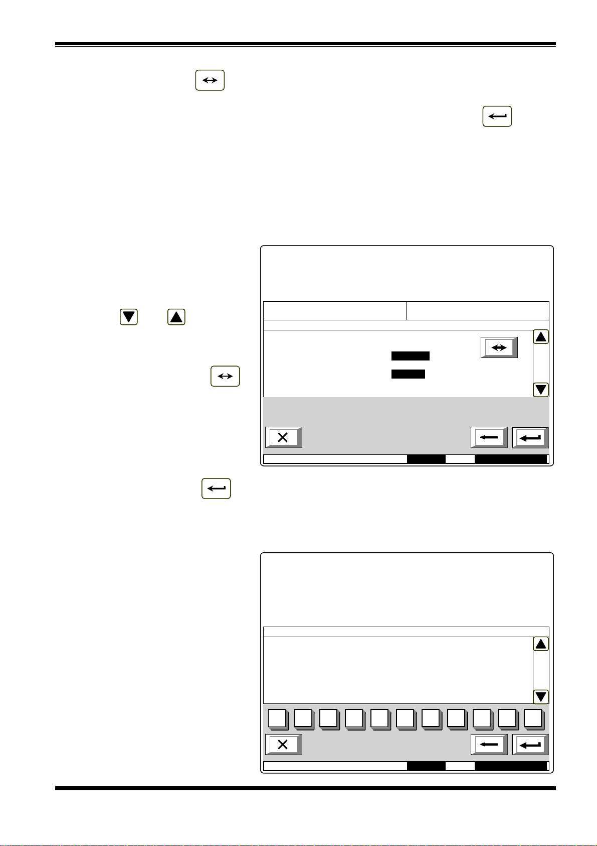
UniPOS Interactive Fire ControlPanel IFS7002
M
15:
0
M
14:
3
Simultaneously, the number in the Go to field will be deleted; i.e. the field is deactivated.
When you press button the detector status is being changed alternatively from DISABLED
to ENABLED and reverse; in the panel bottom left section appears a reminder Data not saved.
Changes (disable/enable addressable fire detector) are accepted if you press button and the
Go to field is empty – then the reminder Data not saved disappears.
12.3.1.3. Menu Outputs
The menu is used for disabling and enabling outputs (monitored outputs and addressable output
modules. It contains the following subordinate menu and functions:
− Monitored outputs;
− Addr Outputs Loop1;
− Addr Outputs Loop 2.
Upon activation of function
Monitored outputs a screen
displaying the status of the control
FIRE CONTROL PANEL IFS7002
UniPOS
panel’s monitored outputs appears:
Buttons and appearing
in the right panel section allow the
user to switch between the first and
the second monitored output.
When you press button
the monitored output status is being
Faults total: 00000
Disables total: 003
System functions/Disables/Outputs
Monitored output 1: DISABLEDDISABLED
Monitored output 2: ENABLED
Failed Outputs: 00000
Disabled Outputs: 001
changed alternatively from
DISABLED to ENABLED and
reverse; in the panel bottom left
section appears a reminder Data not
saved. Changes (disable/enable
ode:DAY
9:46 Mon 21Mar 2005
addressable monitored output) are
accepted if you press button and the Go to field is empty – then the reminder Data not saved
disappears.
Menus Addr Outputs Loop1 and Addr Ouputs Loop 2 have identical layout. Enter the menus to
display one of the following screens:
− If no disabled addressable
output modules are available:
System functions/Disables/Outputs Go to:
Disabled Outputs - total Loop1 000
Loop 1
OUTPUT:
1 2
0
ode:DAY
FIRE CONTROL PANEL IFS7002
UniPOS
3 4 5
6 7
9:10 Mon 21Mar 2005
8
9 С
Instruction Manual Page 49
Revision 2.05 Of 107

UniPOS Interactive Fire ControlPanel IFS7002
M
15:
0
M
15:
1
− If disabled addressable
output modules are available
– the first disabled
FIRE CONTROL PANEL IFS7002
UniPOS
addressable output module
will be displayed, and the text
message for the device will
appear in the panel bottom
section:
Buttons and seen in the
right panel section allow the user to
switch between the next and the
previous disabled addressable output
Faults total: 00000
Disables total: 003
System functions/Disables/Devices Go to:
Disabled Outputs - total Loop1 002
Loop 1
OUTPUT: 005 DISABLED
Point 1.005
1 2
0
3 4 5
Failed Outputs: 00000
Disabled outputs: 001
6 7
8
9 С
module (if any).
Using the digit buttons you may
enter in the Go to field a random 3digit address for the module in the
ode:DAY
9:10 Mon 21Mar 2005
loop. To edit the number press
button and the last entered digit will be deleted.
С
When you press button after a number is entered in the Go to field, the status of the
addressable output module whose number is selected, will be displayed:
− If the selected number is 0, the status of Device 1 will be displayed;
− If the selected number is higher than 125, the status of Device 125 will be displayed.
Simultaneously, the number in the Go to field will be deleted; i.e. the field is deactivated.
When you press button the addressable output module status is being changed
alternatively from DISABLED to ENABLED and reverse; in the panel bottom left section appears a
reminder Data not saved. Changes (disable/enable addressable output module) are accepted if you
press button and the Go to field is empty – then the reminder Data not saved disappears.
12.3.2. Menu Zones in Test
The menu is used to enable or disable test operation in fire alarm zones. Enter the menu to
display one of the two screens:
− If no zones in test are
available:
System functions/Test/Zones Go to:
Zones in test - total 000
ZONE:
FIRE CONTROL PANEL IFS7002
UniPOS
0
ode:DAY
1 2
3 4 5
6 7
9:22 Mon 21Mar 2005
8
9 :С
Instruction Manual Page 50
Revision 2.05 Of 107

UniPOS Interactive Fire ControlPanel IFS7002
M
15:
5
M
15:
1
− If some zones in test are
available, the first zone in test
will be displayed, and in the
FIRE CONTROL PANEL IFS7002
UniPOS
panel bottom section will
appear the text message of
the zone:
Buttons and seen in the
right panel section allow the user to
switch between the next and the
previous zone in test (if any).
System functions/Test/Zones Go to:
Zones in test - total 002
ZONE: 001 IN TEST
Zone 001
Using the digit buttons you may
enter in the Go to field a random 3-
1 2
0
3 4 5
6 7
8
9 С
digit number of the zone. To edit the
number press button and the last
entered digit will be deleted.
С
ode:DAY
9:22 Mon 21Mar 2005
When you press button after a number is entered in the Go to field, the status of the zone
whose number is selected, will be displayed:
− If the selected number is 0, the status of Zone 1 will be displayed;
− If the selected number is higher than 250, the status of Zone 250 will be displayed.
− If the zone has not been formed yet, instead of text message of the zone appears Disabled
zone;
− If the zone has not been formed yet, instead of text message of the zone appears Free zone;
Simultaneously, the number in the Go to field will be deleted; i.e. the field is deactivated.
By pressing the button the zone status is alternatively changed from IN TEST to NOT IN
TEST and reverse, and in the bottom left section appears the reminder Data not saved. The changes
(enable/disable test operation in fire alarm zone) take effect if button is pressed (and the Go to
field is empty); then the reminder Data not saved is cleared.
12.3.3. Function Set Clock
The function is used to set the
real time clock of the control panel to
the correct time. Enter the function to
FIRE CONTROL PANEL IFS7002
UniPOS
display the screen:
Calendar date, day of the week,
the time and the value of the
calibration index are visualized, as
per the moment when the function
was activated. The cursor is located
over the first position in the first line
(Date).
Buttons and in the right
System functions/Clock
Date (dd-mm-yy):21-03-05
Day: Monday
Time (hh:mm:ss):15:56:31
Calibration: +10
1 2
0
3 4 5
6 7
8
9 С
panel section allow the user to move
between the lines on the screen.
To set the correct date and time
ode:DAY
6:31 Mon 21Mar 2005
(line one and three) use:
− The digit buttons – to enter a specific digit on the position of the cursor;
− Buttons and – to move the cursor one position to the left or one position to the right.
Instruction Manual Page 51
Revision 2.05 Of 107

UniPOS Interactive Fire ControlPanel IFS7002
M
17:
4
M
17:
2
To set the current day of the week (line two) use buttons and – they will display the
previous or the next day of the week. Moving from Monday to previous day will set the day to Sunday;
moving from Sunday to next day will set the day to Monday.
The calibration index (line four) can be edited using buttons and – respectively
decreasing or increasing the index by a single calibration device until the minimum or maximum value
is reached (–30 / +30). Each positive device accelerates the clock at the rate of 10,7s per month;
each negative device delays the clock at the rate of 5,35s per month. The maximum rate is е +5,5min
per month or -2,75min per month.
While changing the values in the bottom left section appears the reminder Data not saved.
Changes take effect when you press button , then the reminder Data not saved is cleared.
12.3.4. Function Set Mode
The function allows the user to set the mode of operation of the fire control panel (Mode:DAY or
Night Mode). While operating in Night Mode, the control panel ignores Fire condition stage I (Phase 1
of fire condition); i.e. upon activation of automatic fire detector and manual activation of manual call
point, the control panel will always enter Fire condition stage II (Phase 2 of fire condition).
Enter the menu to display the
screen:
FIRE CONTROL PANEL IFS7002
UniPOS
The current mode of operation is
displayed in inversive colours – white
letters on black background.
Buttons and in the right
panel section allow to alternatively
change the mode of operation.
When the mode is changed, in
the bottom section appears the
System functions/Set Mode
Mode:DAY
Mode:NIGHT
reminder Data not saved.
Changes take effect when you
press button , then the
reminder Data not saved is cleared.
12.3.5. Function Check LEDs and Buzzer
The function allows checking the
LEDs and the local sounder. Enter
the function to display the following
screen:
When you press button
which is in the middle of the display,
the check-up operation starts –
control panel’s LEDs illuminate and
the local sounder produces a
continuous sound. The text message
on the display changes: To stop the
Check push button .
ode:DAY
FIRE CONTROL PANEL IFS7002
Check LEDs and Buzzer
To start the Check
ode:DAY
9:43 Mon 21Mar 2005
UniPOS
push button
3:29 Mon 21Mar 2005
Instruction Manual Page 52
Revision 2.05 Of 107

UniPOS Interactive Fire ControlPanel IFS7002
M
19:
3
Press the button once again to discontinue the check-up operation; the LEDs and the local
sounder restore their initial state.
The operation of buttons and is extended – except for the basic functions they also
discontinue the check-up if it has been started.
Note: LED System Error and the local sounder are activated or deactivated a few seconds
later than the rest of the LEDs.
12.4. Menu Set Up
This is the menu for Set Up condition (see section
13).
Access to Set Up menu is
allowed at Access Level 3А;
accordingly as soon as you enter the
FIRE CONTROL PANEL IFS7002
UniPOS
menu, a password screen appears:
To enter the password use the
digit buttons – press a button and the
relevant digit will be inserted in the
place pointed by the cursor „_”, and
the previous text and the cursor itself
move one position to the right. Move
the cursor to the right or to the left
PASSWORD Level 3
Enter Password: _
using buttons and . Press
button to delete:
С
1 2
0
3 4 5
6 7
8
9 С
− The digit under the cursor, if
any;
ode: DAY
6:15 Mon 21Mar 2005
− The digit to the left of the
cursor if no digit is under the cursor.
Password maximum length is 10 symbols. If you press a digit button after a 10-symbol password
is already entered, the extra digit is not accepted.
If the password is not correct, when you press button all digits are deleted and the cursor
moves back to initial position. If a password for Access Level 3 is entered, press button and the
fire control panel enters Set Up mode: fire detectors are being reset, monitored and addressable
outputs are being switched off and the faults are being cleared. During this operation the message
Please wait appears on the screen; as soon as the operation is completed, the menu Set Up is
activated.
13. Set Up Mode
13.1. Description Set Up mode is used for setting the configuration parameters of the control panel. Access to the Set Up screen is provided through
Up (see section
12.4).
Information and Control Mode – submenu Set
When the control panel enters Set Up mode, it exits all other conditions and discontinues the
service of fire alarm zones, addressable devices, monitored outputs and other periphery devices (all
outputs are switched off). The panel can be controlled via the keypad provided for the purpose. Upon
exit of Set Up mode, reset of the control panel is performed.
In Set Up mode only the green LED indicator (Power supply)is illuminated. The local
sounder is off.
The displayed screens have a tree structure of subordinate menus (Appendix 2b). Transition to a
lower hierarchy menu is performed via button (Enter); to revert to a previous/ upper hierarchy
Instruction Manual Page 53
Revision 2.05 Of 107

UniPOS Interactive Fire ControlPanel IFS7002
menu use button (Cancel). To move between elements of a single menu use buttons
(Up) and (Down) – when the menu appears as ascending window from the left bottom corner of
the screen, or buttons (Move Up) and (Move down) – when the menu appears on a panel in
the middle of the screen. To exit the condition use button (Exit) or press repeatedly button
(Cancel) until you reach the main menu.
The screens provided for parameter changes and command execution (command screens) are of
the lowest hierarchy. When a screen for parameter changes is activated, a pointer indicating the
current parameter, subject to changes, appears. The pointer may be visualized as:
− a cursor, indicating the position where:
♦ a symbol will be inserted – if there is a symbol under the cursor and a text at the
cursor’s right side, they will be moved one position to the right;
♦ a symbol will be deleted – if there is a symbol under the cursor, it will be deleted; the
text at the right side will be moved one position to the left; if there is no symbol under
the cursor, the symbol to the left will be deleted.
− an arrow, pointing over the parameter;
− a text in inversive colours.
To move between the parameters use buttons (next parameter) and (previous parameter).
When a parameter is changed, in the bottom left section of the panel appears the reminder Data not
saved. To save the changes press button and the reminder Data not saved is cleared.
Menu Set Up contains the following subordinate menus and functions:
− Panel configuration;
− Panel parameters;
− Loops;
− Zones;
− Inputs;
− Initialization;
− Checks;
− New Passwords;
− Default parameters;
− Clear Archive.
13.2. Menu Panel configuration
The menu is used to set up:
− the local network where the control panel is included in:
♦ if a local network is available, it can be switched on or off;
♦ if no network is available, the message None appears in the field and the parameter
remains inactive;
− the periphery devices in the control panel:
♦ if periphery devices are present they can be switched on or off;
♦ if no periphery devices are present, the message None appears in the field and the
parameters remains inactive;
− the power loop – it can be switched on or off;
− the language of the messages – language options are Bulgarian or English.
Instruction Manual Page 54
Revision 2.05 Of 107

UniPOS Interactive Fire ControlPanel IFS7002
M
14:
1
M
12:
5
The menu has the following
layout:
The information for the first
active parameter is displayed in
inversive colours (white letters on
black background). Buttons and
at the right panel side allow the
user to move between the active
parameters only.
Panel configuration
Local Network: none
Periphery Module 1: none
Periphery Module 2: none
Periphery Module 3: none
Power loop: On
Language: English
To edit the parameters use
button – each time you press it
the parameter value changes to the
next acceptable value.
ode: DAY
1:18 Tue 22Mar 2005
13.3. Menu Panel parameters
Use the menu when the control panel is integrated into a local network of panels (see Interactive
Fire Control Panel IFS7002 – Operation in Local Network).
13.4. Menu Loops
The menu is provided for set up of fire alarm loops and devices integrated in the loops. It contains
two submenus of identical layout – for Loop 1 and for Loop 2. Each submenu contains:
− Menu Loop parameters;
− Menu Device parameters.
13.4.1. Menu Loop parameters
The menu allows the user to
adjust the parameters of the fire
alarm loop:
− Loop status - On or Off
− Maximum current value of the
loop;
− Number of devices integrated
in the loop.
To edit the Status parameter use
Set Up Loop 1
Status: On
Max current (1 – 120 mA): 120 mA
Number of Devices (0 – 125): 37
button – press the button to
alternatively change the parameter
1 2
0
3 4 5
6 7
8
9 С
from On to Off and vice versa.
Use the digit buttons to edit the
parameters Maximum current and
Number of devices. When you press
button the digit at the cursor’s
С
ode: DAY
8:38 Tue 22Mar 2005
left side is deleted.
If the values of Maximum current and Number of devices are out of the specified limits they will
not be accepted and saved when you press button and the reminder Data not saved will
remain active.
Instruction Manual Page 55
Revision 2.05 Of 107

UniPOS Interactive Fire ControlPanel IFS7002
M
15:
3
13.4.2. Menu Device parameters
The menu is used to set up the parameters of the devices integrated in the fire alarm loop Enter
the menu to display:
− If no devices are included in the loop – a screen with the message No devices included; the
only option is to exit the menu;
− If some devices are included
in the loop – a screen where
you may select the device
whose parameters are to be
set up:
For each device are displayed:
− Its number (address) in the
loop – in the top line;
− Text message – in the line
beneath.
The current device is pointed by
arrow – „>>”.
SetUp Loop 1 Devices Total: 37 Go to:
>>Аddr1
Point 1.001
Аddr2
Point 1.002
Аddr3
Point 1.003
Аddr4
Point 1.004
Адddr5
Point 1.005
Аddr6
Point 1.006
Аddr7
Point 1.007
1 2
0
3 4 5
6 7
8
9 С
Buttons and at the right
panel side are visualized if more than
one device is available in the loop;
the Go to field on the panel heading
ode: DAY
4:53 Tue 22 Mar 2005
and the digit buttons appear if more
than 7 devices are available in the loop. Press a digit button, the Go to field is activated and a random
3-digit address for each device in the loop can be entered. To edit the address use button ; press
С
it and the last entered digit will be deleted.
Press button after you entered a number in the Go to field; then the device whose address
is in the field will be selected:
− If the number is 0, the device having address 1 will be selected;
− If the number is higher than the actual number of devices in the loop, the device having the
highest address number will be selected
Simultaneously, the number in the Go to field will be deleted, i.e. the field is deactivated.
Press button after you entered a number in the Go to field and the field will be deactivated.
Press button when the Go to field is empty and a menu containing a group of parameters
for the selected device will be displayed:
− Menu Device parameters;
− Screen Text message.
Instruction Manual Page 56
Revision 2.05 Of 107

UniPOS Interactive Fire ControlPanel IFS7002
M
14:
1
L
R
а→А
2
a
1Ω09 3
d
4
g
5
j
pqrs
9
wxyzM
16:
1
13.4.2.1. Menu Device parameters
The menu is used for
addressable device parameters set
up:
− Device temperature class –
only for addressable devices
type FD7110, FD7120,
FD7130, FD7160 and
FD7201;
− Device status – On or Off.
As a heading is displayed the
type of the device:
SetUp Device 1 Loop 1
Device type: FD7110
Class: A2S
Status: On
To edit the parameters use
button – press it to change the
parameter to the next acceptable
value.
ode: DAY
3:30 Tue 22Mar 2005
13.4.2.2. Screen Text message
The screen is used to assign and edit text messages for each addressable device. Upon
activation of the screen a check up for available external keyboard is performed.
13.4.2.2.1. Built-in keypad
If no external keyboard is
integrated in the control panel, the
following screen appears:
To edit the text use the buttons
having symbols – when you press a
button, the symbol appears over the
position of the cursor, and the
previous text is moved one position
to the right. The cursor remains for 1
s over the same position; if you press
SetUp Device 1 Loop 1
Point 1.001_
it again, the symbol will be changed
6
7
by the next one marked on the button
(the symbol Ω marked on the second
button means, that the figure 1 is in
combination with punctuation marks).
1 s after the last pressing the cursor
ode: DAY
bc
ef
AT/CY
hi
kl
mno
8:38 Tue 22Mar 2005
8
tuv
С
moves to the next position to the
right. If you press another button
during this 1 second, the cursor first moves one position to the right and then the new symbol is
inserted. The maximum length of the message is 40 symbols. If you press a button after a 40-symbol
message is already entered, the text will not be accepted and the symbol will not be inserted (the
cursor moves one position to the right if the end of the text message is not reached yet).
Press button to delete:
С
− The symbol under the cursor, if any;
− The symbol to the left of the cursor, if there is no symbol under it.
Press button or to move the cursor one position to the left or to the right.
Instruction Manual Page 57
Revision 2.05 Of 107

UniPOS Interactive Fire ControlPanel IFS7002
M
15:
0
L
←
CYR
L
C
Button changes the case from lowercase to uppercase, button changes the
А→а а→А
uppercase to lowercase.
Button changes the Latin font to Cyrillic font; button changes the Cyrillic font to
YR/LATLAT/CYR
Latin font.
13.4.2.2.2. External keyboard
If an external keyboard is
included to the fire control panel the
following screen appears:
To edit the text use the buttons
having symbols – when you press a
button, the symbol appears over the
position of the cursor, and the
previous text and the cursor move
one position to the right
SetUp Device 1 Loop 1
Point 1.001_
The maximum length of the
message is 40 symbols. If you press
a button after a 40-symbol message
is already entered, the text will not be
accepted and the symbol will not be
inserted
ode: DAY
AT
7:41 Tue 22Mar 2005
Press button „Delete” to delete:
− The symbol under the cursor, if any;
− The symbol to the left of the cursor, if there is no symbol under it.
Press button or to move the cursor one position to the right or to the left.
← →
Use the additional digit keypad to:
− Insert digits – when the LED „Num” is illuminated;
− Move the cursor via buttons „4 / ←” and „6 / →” (analogically to buttons and ) –
←
when the LED „Num” is extinguished;
− Delete a symbol via button „Del” (analogically to button „Delete”) – when the LED „Num” is
extinguished.
The mode of operation of the additional keypad, indicated by the LED „Num” can be changed via
button „Num Lock”.
Button „Caps Lock” alternatively changes the case from lowercase to uppercase (LED „Caps” or
„А” illuminate to indicate uppercase).
Button „Ctrl” alternatively changes Latin fonts to Cyrillic fonts; the active font is indicated in the
bottom section of the display – indicators and .
AT
To save a text message press button on the built-in keypad or press button („Enter”)
on the external keypad.
To exit the screen and revert to upper hierarchy menu use button on the built-in keypad or
button („Back Space”) on the external keypad.
To exit Set Up use button on the built-in keypad or button „Esc” on the external keypad.
Instruction Manual Page 58
Revision 2.05 Of 107
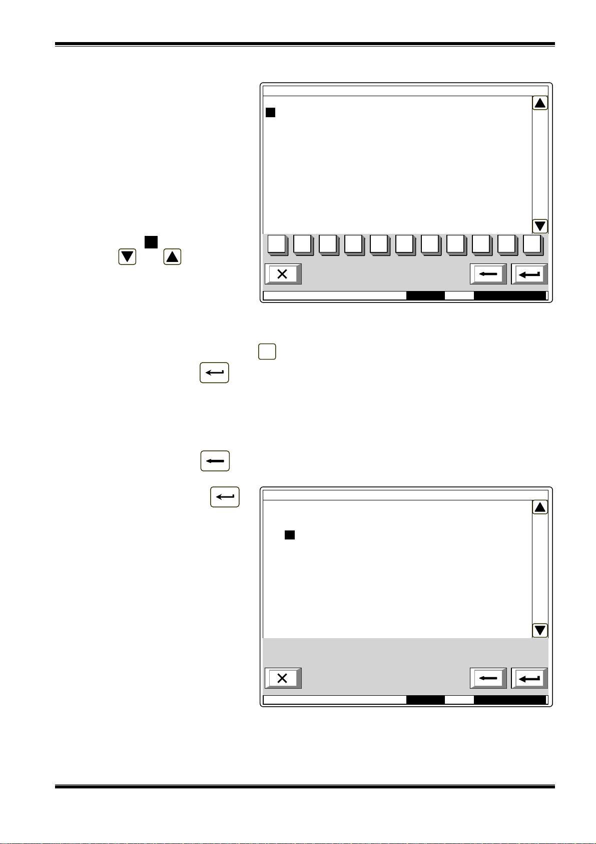
UniPOS Interactive Fire ControlPanel IFS7002
M
12:
2
M
11:
4
Z
6
13.5. Menu Zones
The menu allows the user to
form fire alarm zones and to set up
their parameters. Enter the menu to
display a screen for zone selection:
For each zone are displayed:
− Its number – in the top line;
− The text message – in the
line beneath.
The free zone is displayed first,
i.e. the first zone where no devices is
integrated in. The selected zone is
pointed by arrow „>>”.
SetUp Zones Zones: 017 Go to:
>> Free zone: 18
Zone 18
1 Zone 1
Zone 1
2 Zone 2
Zone 2
3 Zone 3
Zone 3
4 Zone 4
Zone 4
5 Zone 5
Zone 5
6 Zone 6
one
1 2
0
3 4 5
6 7
8
9 С
Buttons and in the right
panel section are visualized if at least
one zone is available; the Go to field
in the heading and the digit buttons
ode: DAY
0:53 Wed 23Mar 2005
appear if more than 6 zones are
available.
When you press a digit button the Go to field is activated; you can enter a random 3-digit number
of a zone. To edit the number use button - the last inserted digit will be deleted.
С
When you press button after you entered a number in the Go to field, the zone whose
address is in the field will be selected:
− If the number is 0, Zone 1 will be selected;
− If the number is higher than the actual number of fire alarm zones, the zone having the
highest address number will be selected.
Simultaneously the number in the Go to field is deleted, i.e. the field is deactivated.
When you press button after you entered a number in the Go to field, the field will be
deactivated.
When you press button
and the field is empty, a menu
containing groups of parameters for
the selected zone appearsа:
− Menu Devices;
− Menu Fire Phase 1 Outputs;
− Menu Fire Phase 2 Outputs”;
− Menu Zone parameters;
− Screen Text message.
SetUp Zone 1
>> Devices
Fire Phase 1 Outputs
Fire Phase 2 Outputs
Zone parameters
Text message
ode: DAY
2:21 Wed 23Mar 2005
Instruction Manual Page 59
Revision 2.05 Of 107

UniPOS Interactive Fire ControlPanel IFS7002
M
13:
2
M
13:
1
Lp
7
13.5.1. Menu Devices
The menu allows the user to integrate (to include) a device in a zone and to exclude a device
from a zone. It contains the following submenus and screens:
− Screen List of devices;
− Screen Set zone as free;
− Menu Remove address;
− Menu Remove address range;
− Menu Add address;
− Menu Add address range.
If no devices are present in the zone (free zone) screen Set zone as free, menu Remove address,
and menu Remove address range are not accessible. If 60 devices are already added to the zone
(the zone is full), the menu Add address and menu Add address range are not accessible.
13.5.1.1. Screen List of devices
The screen displays a list of fire
detectors included in the zone. For
each devices is displayed the loop
where it is included and the device
address in the loop:
SetUp Zone 1 List of devices Total: 17
Lp1 Аddr1 Lp2 Аddr110
Lp1 Аddr2 Lp2 Аddr114
Lp1 Аddr3
Lp1 Аddr4
Lp1 Аddr10
Lp1 Аddr11
Lp2 Аddr1
Lp2 Аddr2
Lp2 Аddr6
Lp2 Аddr7
Lp2 Аddr12
Lp2 Аddr13
Lp2 Аddr14
Lp2 Аddr16
2 Аddr1
ode: DAY
9:31 Wed 23Mar 2005
If no fire detectors are integrated in the zone, a screen with the text message Free zone appears.
13.5.1.2. Screen Set zone as free
The command screen Set zone
as free allows the user to remove all
devices from the zone.
Press button to remove
the devices from the zone and to exit
the screen.
SetUp Zone 1 Set Zone as free
All addresses will be removed from the Zone!
– confirm
– cancel
ode: DAY
Warning!
8:25 Wed 23Mar 2005
Instruction Manual Page 60
Revision 2.05 Of 107

UniPOS Interactive Fire ControlPanel IFS7002
M
13:
4
P
2
.
13.5.1.3. Menu Remove address
The menu allows the user to
remove particular devices from the
zone:
For each device is displayed:
− Its number in the zone, the
loop it is included in, and the
address in the loop – in the
top line
− The text message – in the
line beneath.
The devices in a zone are
SetUp Zone 1 Remove address Go to:
Total: 17
>> 1 Lp1 Аddr1
Point 1.001
2 Lp1 Аddr2
Point 1.002
3 Lo1 Аddr3
Point 1.003
4 Lp1 Аddr4
Point 1.004
5 Lp1 Аddr10
Point 1.010
6 Lp1 Аddr11
Point 1.011
7 Lp2 Аddr1
oint
1 2
0
001
3 4 5
6 7
8
9 С
numbered according to the following
sequence:
− Devices in Loop 1
obtain numbers
ode: DAY
1:53 Wed 23Mar 2005
increasing along with
the addresses;
− Devices in Loop 2 obtain numbers increasing along with the addresses.
The selected device is pointed by arrow – „>>”.
Buttons and in the right panel section are visualized if more than one device is available;
the Go to field and the digit buttons appear if more than 7 devices are available in the zone.
Press a digit button and the Go to field is activated; you can enter a random 2-digit number for a
device in the zone. To edit the number, use button , press the button to delete the last inserted
С
digit.
When you press button and a number is already entered in the Go to field, the devices
whose number is in the field will be selected:
− If the number is 0, the first device in the zone will be selcted;
− If the number is higher than the catual number of devices in the zone, the last device will be
selected.
Simultaneously, the number in the Go to field will be deleted, i.e. the field is deactivated.
When you press button after a number is enterd in the Go to field, the field itself is
deactivated.
When you press button and the Go to field is empty, the devices will be removed from the
zone. When the last device is removed from the zone a screen with the text message Free zone
appears; the only option is to exit the menu.
Instruction Manual Page 61
Revision 2.05 Of 107

UniPOS Interactive Fire ControlPanel IFS7002
M
10:
0
M
:
4
13.5.1.4. Menu Remove address range
The menu allows the user to
remove a group of devices from the
zone, having consequent addresses
in a single loop:
For each group of devices the
user shall enter:
− The loop where the group is
included in – if no value is
entered, by default will be
accepted Loop 1;
SetUp Zone 1 Remove address range
Total: 17
Loop: _
From address:
To address:
− The address of the first
device in the group – if no
1 2
0
3 4 5
6 7
8
9 С
value is entered by default
will be accepted Address 1;
− The address of the last
device in the group – if no
ode: DAY 9
0:40 Thu 24Mar 2005
value is entered by default
will be accepted Address 1.
When you press button a
screen with warning message
appears:
Press button to remove
from the zone devices included in the
group. The screen displays:
− If some devices are still in the
zone – a screen for the
selection of a group of
SetUp Zone 1 Remove address range
Warning!
From the Zone will be removed Devices:
Loop: 1
From address: 5
To address: 7
– confirm
– cancel
devices for removal, and the
most recent data are saved;
− If no devices are left in the
zone – a screen with the text
message Free zone; the only
option is to exit the menu.
ode: DAY
5:51 Thu 24Mar 2005
In both cases the number of the removed devices from the zone is displayed in the bottom section of
the panel.
Instruction Manual Page 62
Revision 2.05 Of 107

UniPOS Interactive Fire ControlPanel IFS7002
M
10:
0
13.5.1.5. Menu Add address
The menu allows the user to add separate devices to the zone. Enter the menu to display:
− If no free device is available – a screen with the text message All addresses are included in
zones, the only option is to exit the menu;
− If a free device is available –
a screen displaying the first
device that is not included in
a zone:
For each device not included in a
zone is displayed:
− The loop it is integrated in
and the address in the loop –
in the top line;
− Text message – in the line
SetUp Zone 1 Add address Go to:
Total: 17
>>Lp1 Аddr1
Point 1.001
beneath.
The selected message is pointed
1 2
0
3 4 5
6 7
8
9 С
by arrow – „>>”.
Buttons and in the right
panel section, the Go to field in the
heading of the panel and the digit
ode: DAY
8:25 Thu 24Mar 2005
buttons are visualized if more than
one free device is available.
When you press a digit button, the Go to field is activated; you can enter a random 3-digit number
for a device in the field. To edit the number push button , and the last inserted digit is deleted.
С
The devices get numbers in accordance with the following sequence: from the first decive in Loop
1 to the last device in Loop 1; from the first device in Loop 2 to the last device in Loop 2.
When you press button and a number is already entered in the Go to field, the first free
device whose numer is equal to or higher than the number in the field will be selected:
− If the number is 0, the first free device will be selected;
− If the number is higher than the number of the last available free device, then the last device
will be selected.
Simultaneously, the number in the Go to field is deleted, i.e. the field is deactivated.
When you press button and a number is already entered in the Go to field, then the field
will be deactivated.
When you press button and the field is empty, then the device will be added to the zone.
As soon as you add the last available free device, a screen with the text message All addresses are
included in zones; the only option is to exit the menu. After 60
th
device is added to the zone, a screen
with the text message Full Zone appears; the only option is to exit the menu.
Instruction Manual Page 63
Revision 2.05 Of 107

UniPOS Interactive Fire ControlPanel IFS7002
M
11:
3
13.5.1.6. Menu Add address range
The menu allows the user to add
a group of devices, having
consequent addresses in a single
loop, to the zone:
For each group of devices the
user shall enter:
− The loop where the group is
included in – if no value is
entered, by default will be
accepted Loop 1;
SetUp Zone 1 Add address range
Total: 17
Loop: _
From address:
To address:
− The address of the first
device in the group – if no
1 2
0
3 4 5
6 7
8
9 С
value is entered by default
will be accepted Address 1;
− The address of the last
device in the group – if no
ode: DAY
5:12 Thu 24Mar 2005
value is entered by default
will be accepted Address 1.
Press button to add the free devices in the group to the zone; the limit of 60 devices in a
zone is accordingly observed. The following information is displayed:
− If less than 60 devices are available in the zone – a screen for the selection of a group of
devices that are to be added, and the most recent data is saved;
− If 60 devices are already added to the zone – a screen with the message Full Zone appears;
the only option is to exit the menu.
In both cases the number of the devices added to a zone is displayed in the bottom section of the
panel.
Instruction Manual Page 64
Revision 2.05 Of 107

UniPOS Interactive Fire ControlPanel IFS7002
M
12:
3
M
11:
5
13.5.2. Menus Fire Phase 1 Outputs and Fire Phase 2 Outputs
The menus alow the user to associate outputs to the zone, that wil be triggered in fire condition
(phase Fire condition stage I and phase Fire condition stage II). The menus contain:
− Menu Panel Outputs
− Screen List of addressable outputs;
− Menu Remove addressable output;
− Menu Add addressable output.
If no associated addressable outputs are available, menu Remove addressable output is not
accessible. If 30 addressable outputs are associated to the zone, menu Add addressable output is
not accessible.
13.5.2.1. Menu Panel Outputs
Menu Panel Outputs allows the
user to associate control panel
outputs to the zone, in accordance
with the Fire phase:
To edit the parameters use
button – press it to
alternatively change the value of the
current parameter to Yes (the output
will be activated upon relevant phase
SetUp Zone 1 Fire Phase 1 Outputs
Panel Outputs
Monitored Output 1 No
Monitored Output 2 No
Relay Output Yes
of Fire condition in the zone) and to
No (the output will remain inactive
upon relevant phase of Fire condition
in the zone) and vice versa.
ode: DAY
3:31 Thu 24Mar 2005
13.5.2.2. Screen List of addressable outputs
The screen displays a list of
addressable outputs, associated to
the zone. For each output is
displayed the loop where the output
module is included in, its address in
the loop and the number of the
output in the module, if more than
one.
SetUp Zone 1 Fire Phase 1 Outputs
List of addressable Outputs Total: 11
Loop 1 Аddr 7.2 Loop 2 Аddr 13.2
Loop 1 Аddr 7.3
Loop 1 Аddr 7.4
Loop 1 Аddr 7.5
Loop 1 Аddr 7.6
Loop 1 Аddr 8
Loop 2 Аddr 9
Loop 2 Аddr 10.1
Loop 2 Аddr 11.1
Loop 2 Аddr 12
ode: DAY
8:51 Thu 24Mar 2005
If no addressableoutputs are associated to the zone, a screen with the message No addressable
outputs activated upon Fire Condition Phase X (X stands for phase number – 1 or 2)
Instruction Manual Page 65
Revision 2.05 Of 107

UniPOS Interactive Fire ControlPanel IFS7002
M
13:
4
P
2
.009
13.5.2.3. Menu Remove addressable output
The menu allows the user to
remove separate addressable
outputs associated to the zone:
For each output is displayed:
− Its number in the zone; the
loop where the device is
included; the addresss of the
device in the loop and the
number of the output in the
device, if more than one– in
the top line;
− Text message for the devices
SetUp Zone 1 Fire Phase 1 Outputs Go to:
Remove addressable Output Total: 17
>> 1 Lp1 Аddr7.2
Point 1.007
2 Lp1 Аddr7.3
Point 1.007
3 Lp1 Аddr7.4
Point 1.007
4 Lp1 Аddr7.5
Point 1.007
5 Lp1 Аddr7.6
Point 1.007
6 Lp1 Аddr8
Point 1.008
7 Lp2 Аddr9
oint
1 2
0
3 4 5
6 7
8
9 С
– in the line beneath.
The selected output is poitned by
arrow – „>>”.
Buttons and in the right
ode: DAY
4:08 Thu 24Mar 2005
panel section are visualized where
more than one output is available, and the Go to field in the heading and the digit buttons appear if
more than 7 outputs associated to the zone are available.
When you press a digit button, the Go to field is activated; you can enter a random 2-digit number
for the output in the zone. To edit the number, use button ; press it to delete the last entered digit.
С
When you press button and a number is already entered in the Go to field the output
whose number is in the field will be selected:
− If the number is 0, the first output assosiated to the zone will be selcted;
− If the number is higher than the actual number of associated outputs, the last output will be
selected.
Simultaneously, the number in the Go to field is deleted, i.e. the field is deactivated.
When you press button and the number is already entered in the Go to field, the field will
be deactivated.
When you press button and the field is empty, the output will be remoced from the zone.
When the last output associated to the zone is removed, a screen with the text message No
addressable outputs activated upon Fire Phase X (X stands for the Phase number – 1 or 2) is
displayed; the only option is to exit the menu.
Instruction Manual Page 66
Revision 2.05 Of 107

UniPOS Interactive Fire ControlPanel IFS7002
M
14:
3
13.5.2.4. Menu Add addressable output
The menu allows the user to associate separate addressable outputs to the zone. Enter the menu
to display:
− If no free addressable outputs, not associated to a zone in accordance with the relevant fire
phase are available – a screen with the message No unused outputs appears; the only option
is to exit the menu;
− If a free addressable output,
not associated to the zone in
accordance with the relevant
fire phase is available – a
screen with the first free
addressable output:
For each addressable output is
displayed:
− The loop where the output
module is included; the loop
SetUp Zone 1 Fire Phase 1 Outputs Go to:
Total: 17
>>Lp1 Аddr25.1
Point 1.025
address and the number of
the output in the module, if
1 2
0
3 4 5
6 7
8
9 С
more than one – in the top
line;
− Text message for the device
– in the line beneath.
ode: DAY
8:45 Thu 24Mar 2005
The selected addressable output
is pointed by arrow – „>>”.
Buttons and in the right panel section are visualized if more that one free addressable
output is available, and the Go to field in the heading and the digit buttons appear if free addressable
outputs in more than one module are available.
When you press a digit button, the Go to field is activated; you can enter a random 3-digit numbr
for a device. To edit the number, use button , press it and the last entered digit will be deleted.
С
The devices obtain numbers according to the following sequence: from the first device in Loop 1
to the last device in Loop 1; from the first device in Loop 2 to the last device in Loop 2.
When you press button and a number is entered in the Go to field, the first free
addressable output whose number is equal to or higher than the number in the field will be selected:
− If the number is 0, the first free addressable output will be selected;
− If the number is higher than the number of the device having the last free addressable output,
the last free addressable output will be selected.
Simultaneously the number in the Go to field is deleted; i.e. the field is deactivated.
When you press button after you entered a number in the Go to field, the field will be
deactivated
When you press button and the Go to field is empty, the output will be added to the outputs
associated to the zone. When the last free addressable output is added, a screen with the message
No unused outputs appears; the only option is to exit the menu. When the 30
th
addressable output is
associated to the zone, a screen with the message Additional addressable outputs can not be
activated upon Fire Phase X (X stands for the phase number – 1 or 2); the only option is to exit the
menu.
Instruction Manual Page 67
Revision 2.05 Of 107

UniPOS Interactive Fire ControlPanel IFS7002
M
15:
4
13.5.3. Menu Zone parameters
The menu is provided for zone
parameters set up:
− Manual call point priority –
when the manual call points
have priority, their response
will trigger Fire condition
phase 2 in the zone; if they
do not have priority, their
response will trigger Fire
SetUp Zone 1 Zone parameters
Manual call point Priority: Yes
Coincidence Mode: No
Time Fire Phase 1 – Phase 2: 120 s
Inspection time: 120 s
condition phase 1 in the
zone; i.e. they will be treated
1 2
0
3 4 5
6 7
8
9 С
as automatic fire detectors;
− Coincidence mode – when
set to this mode, the zone will
enter Fire condition phase 1 if
ode: DAY
1:44 Thu 24Mar 2005
at least 2 low priority fire
detectors are activated;
− Time Fire Phase 1 – Phase 2 – the delay time before the control panel proceeds from fire
condition stage I to fire condition stage II in the zone;
− Inspection time – period of time that, when you press button , will be added to the
remaining time for transition from Fire condition stage I to Fire condition stage II in a zone.
To edit parameters Manual call point priority and Coincidence Mode use button – by
pressing the button you can change the value of the parameter alternatively form Yes to No and vise
versa.
To edit parameters Time Fire Phase 1 – Phase 2 and Inspection time use the digit buttons. When
you press button the digit at the left side of the cursor will be deleted. If the values for Time Fire
С
Phase 1 – Phase 2 and Inspection time are higher than 255, they will be automatically replaced by
255 as soon as the last digit is entered.
Instruction Manual Page 68
Revision 2.05 Of 107

UniPOS Interactive Fire ControlPanel IFS7002
M
15:
5
L
R
а→А
2
a
1Ω09 3
d
4
g
5
j
pqrs
9
wxy
C
13.5.4. Screen Text message
The screen allows the user to insert and edit a text message for a zone. Upon activation of the
screen a check up is being run for included external keyboard.
13.5.4.1. Built-in keypad
If no external keyboard is
included to the control panel, then
the following screen appears:
To edit the text use the buttons
having symbols – when you press a
button, the symbol appears over the
position of the cursor, and the
previous text is moved one position
to the right. The cursor remains for 1
s over the same position; if you press
SetUp Zone 1 Text message
Zone 1_
it again, the symbol will be changed
6
7
by the next one marked on the button
(the symbol Ω marked on the second
button means that the figure 1 is in
combination with punctuation marks).
1 s after the last pressing the cursor
ode:DAY
bc
ef
AT/CY
hi
kl
mno
1:54 Thu 24Mar 2005
8
tuv
С
z
moves to the next position to the
right. If you press another button
during this 1 second, the cursor first moves one position to the right and then the new symbol is
inserted. The maximum length of the message is 40 symbols. If you press a button after a 40-symbol
message is already entered, the text will not be accepted and the symbol will not be inserted (the
cursor moves one position to the right if the end of the text message is not reached yet).
Press button to delete:
С
− The symbol under the cursor, if any;
− The symbol to the left of the cursor, if there is no symbol under it.
Press button or to move the cursor one position to the left or to the right.
Button changes the case from lowercase to uppercase, button changes the
А→а а→А
uppercase to lowercase.
Button changes the Latin font to Cyrillic font, button changes the Cyrillic font to
YR/LATLAT/CYR
Latin font.
Instruction Manual Page 69
Revision 2.05 Of 107
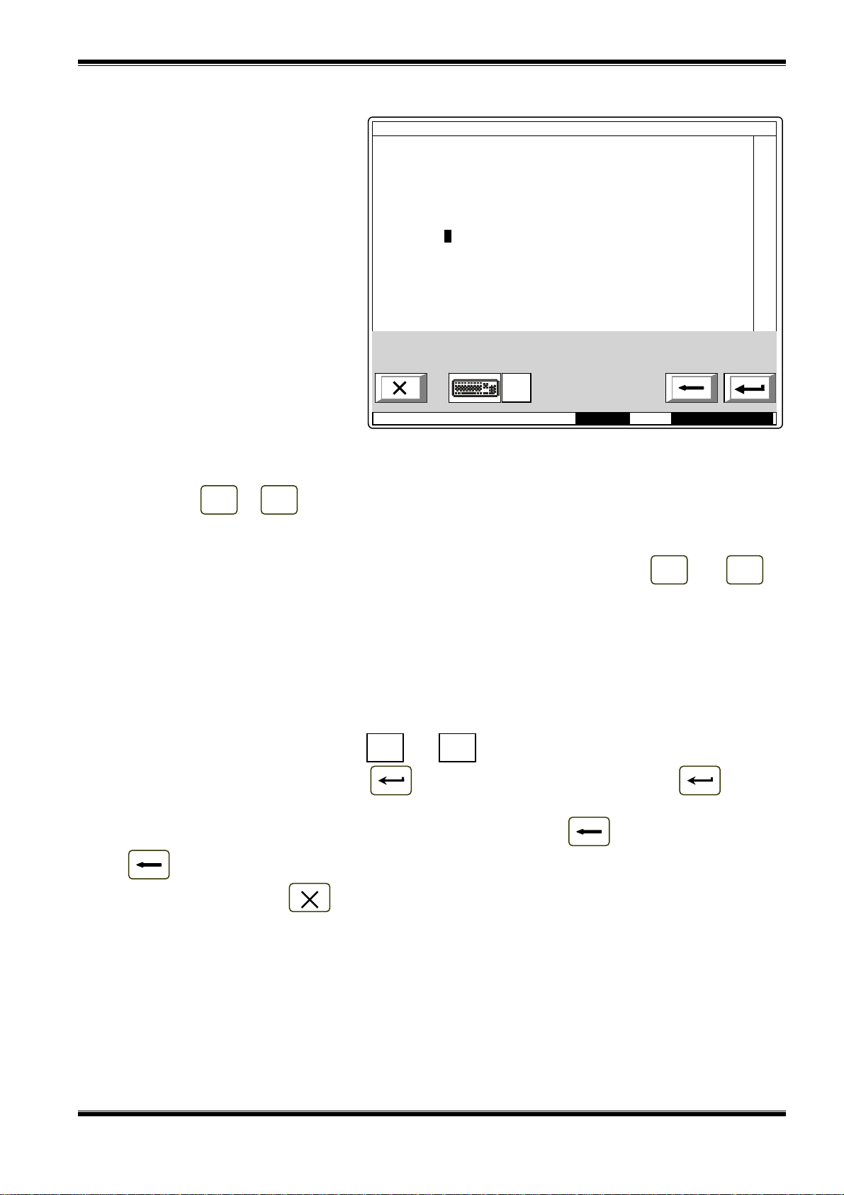
UniPOS Interactive Fire ControlPanel IFS7002
M
16:
0
L
←
CYR
L
13.5.4.2. External keyboard
If external keyboard is included
to the control panel, the followinh
screen appears:
To edit the text use the buttons
having symbols – when you press a
button, the symbol appears over the
position of the cursor, and the
previous text and the cursor move
one position to the right
The maximum length of the
message is 40 symbols. If you press
SetUp Zone 1 Text message
Zone 1_
a button after a 40-symbol message
is already entered, the text will not be
accepted and the symbol will not be
inserted.
ode:DAY
AT
0:13 Thu 24Mar 2005
Press button “Delete” to delete:
− The symbol under the cursor, if any;
− The symbol to the left of the cursor, if there is no symbol under it
Press button or to move the cursor one position to the right or to the left.
← →
Use the additional digit keypad to:
− Insert digits – when the LED „Num” is illuminated;
− Move the cursor via buttons „4 / ←” and „6 / →” (analogically to buttons and ) –
←
when the LED „Num” is extinguished;
− Delete a symbol via button „Del” (analogically to button „Delete”) – when the LED „Num” is
extinguished.
The mode of operation of the additional keypad, indicated by the LED „Num” can be changed via
button „Num Lock”.
Button „Caps Lock” alternatively changes the case from lowercase to uppercase (LED „Caps” or
„А” illuminate to indicate uppercase).
Button „Ctrl” alternatively changes Latin fonts to Cyrillic fonts; the active font is indicated in the
bottom section of the display – indicators and .
AT
To save a text message press button on the built-in keypad or press button („Enter”)
on the external keypad.
To exit the screen and revert to upper hierarchy menu use button on the built-in keypad or
button („Back Space”) on the external keypad.
To exit Set Up use button on the built-in keypad or button „Esc” on the external keypad.
Instruction Manual Page 70
Revision 2.05 Of 107

UniPOS Interactive Fire ControlPanel IFS7002
M
16:
0
13.6. Menu Inputs
The menu allows the user to set the parameters of the addressable inputs. Enter the menu to
display:
− If no addressable input modules are available – a screen with the message No inputs; the only
option is to exit the menu;
− If addressable input modules
are available – a screen for
selection of the first
addressable input whose
parameters are to be set:
For each addressable input is
displayed:
− Loop number, input module
address in the loop and the
number of the input in the
SetUp Inputs Go to:
>>Loop1 Аddr19.1
Point 1.019
module if more than one – in
the top line;
1 2
0
3 4 5
6 7
8
9 С
− Text message for the module
– in the line beneath.
The selected input is pointed by
– „>>”.
ode:DAY
9:46 Thu 24Mar 2005
Buttons and in the right
panel section are visualized where more than one addressable input is available, the Go to field in the
heading and the digit buttons appear if more than one addressable input module is available.
Buttons and allow the user to switch between the next and the previous addressable
input (if any).
When you press a digit button the arrow „>>” will appear before the selected addressable input is
deleted and the Go to field is activated; you can enter a random 3-digit number for the device. To edit
the number press button and the last entered digit will be deleted.
С
Devices obtain numbers according to the following sequence: from first device in Loop 1 to the
last device in Loop1; from the first device in Loop 2 to the last device in Loop 2.
When you press button and a number is entered in the Go to field, the first free
addressable input of the first addressable input module whose number is equal to or higher than the
number in the field will be selected:
− If the number is 0, the first free addressable input will be selected;
− If the number is higher than the number of the last free addressable input module, the last free
addressable input will be selected.
Simultaneously the number in the Go to field is deleted; i.e. the field is deactivated.
When you press button after you entered a number in the Go to field, the field will be
deactivated and the arrow „>>” will appear before the selected addressable output.
Whe you press button and the arrow „>>” is visualized (Go to field is empty) then a menu
containing groups of parameters for the selected addressable output will appear:
− Screen List of addressable outputs;
− Menu Remove addressable output;
− Menu Add addressable output;
− Menu Text message.
Instruction Manual Page 71
Revision 2.05 Of 107

UniPOS Interactive Fire ControlPanel IFS7002
M
17:
3
P
2
.009
M
17:
2
13.6.1. Screen List of addressable outputs
The screen displays a list of
addressable outputs that will be
initiated upon activation of the
addressable input. For each output is
displayed the loop where the output
module is included in, its address in
the loop and the number of the
output in the module, if more than
one.
SetUp Input Lp1 Аddr19.1
List of addressable Outputs Total: 11
Loop1 Аddr7.2 Loop1 Аddr7.6 Loop2 Аddr11.1
Loop1 Аddr7.3 Loop1 Аddr8 Loop2 Аddr12
Loop1 Аddr7.4 Loop2 Аddr9 Loop2 Аddr13.2
Loop1 Аddr7.5 Loop2 Аddr10.1
ode:DAY
6:07 Thu 24Mar2005
If no addressable outputs subject to activation through the addressable input are available, a
screen with the text message No addressable outputs activated by this Input appears.
13.6.2. Menu Remove addressable output
The menu allows the user to
remove separate addressable
outputs, activated by the addressable
input:
For each addressable output is
displayed:
− Its number in the list of
outputs, activated by the
addressable input; the loop
where the module is included;
the address of the module in
SetUp Input Lp1 Аddr19.1 Go to:
Remove addressable Output Total: 11
>> 1 Lp1 Аddr7.2
Point 1.007
2 Lp1 Аddr7.3
Point 1.007
3 Lp1 Аddr7.4
Point 1.007
4 Lp1 Аddr7.5
Point 1.007
5 Lp1 Аdr7.6
Point 1.007
6 Lp1 Аddr8
Point 1.008
7 Lp2 Аddr9
oint
1 2
0
3 4 5
6 7
8
9 С
the loop and the number of
the output in the module, if
more than one – in the top
line;
ode:DAY
4:50 Thu 24Mar 2005
− Text message for the device
– in the line beneath.
The selected addressable output is pointed by arrow – „>>”.
Buttons and in the right panel section are visualized if more that one addressable output
is available, and the Go to field in the heading and the digit buttons appear if more than 7 addressable
outputs activated by the input are available.
When you press a digit button, the Go to field is activated; you can enter a random 2-digit numbr
for the output in the list of outputs activated by the input. To edit the number, use button , press it
С
and the last entered digit will be deleted.
When you press button and a number is entered in the Go to field, the output whose list
number is in the field will be selected:
− If the number is 0, the first output activated bythe addressable input will be selected;
Instruction Manual Page 72
Revision 2.05 Of 107
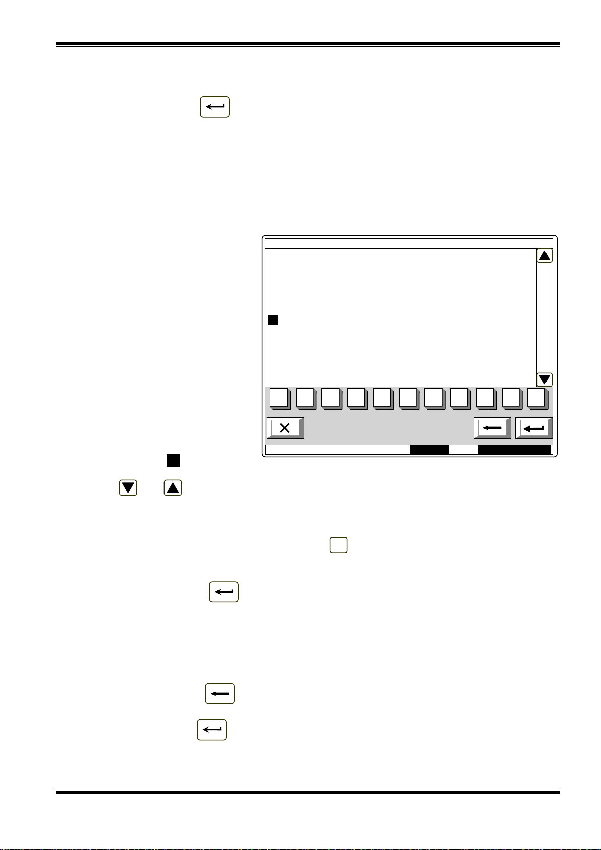
UniPOS Interactive Fire ControlPanel IFS7002
M
17:
5
− If the number is higher than the number of outputs, activated by the addressable input the last
output will be selected.
Simultaneously the number in the Go to field is deleted; i.e. the field is deactivated.
When you press button and the Go to field is empty, the list of outputs activated by the
addressable input will be deleted. When the last output from the list is deleted, a screen with the
message No addressable outputs activated by this input appears; the only option is to exit the menu.
13.6.3. Menu Add addressable output
The menu allows the user to add separate addressable outputs to the list of outputs subject to
activation by the addressable input. Enter the menu to display:
− If no free addressable outputs, not included in the list, are available – a screen with the
message No unused outputs appears; the only optio is to exit the menu;
− If a free addressable output,
not included in the lis, is
available – a screen
displaying the first free
addressable output:
For each addressable output is
displayed:
− The loop where the input
module is included in; the
module address in the loop
SetUp Input Lp1 Аddr19.1 Go to:
Total: 11
>>Lp1 Аddr25.1
Point 1.025
and the number of the output
in the module, if more than
1 2
0
3 4 5
6 7
8
9 С
one – in the top line;
− Text message for the module
– in the line beneath.
The selected addressable output
ode:DAY
3:49 Thu 24Mar 2005
is pointed by arrow – „>>”.
Buttons and in the right panel section are visualized if more than one free addressable
output is available, the Go to field and the digit buttons appear if free addressable outputs in more
than one module are available.
When you press a digit button, the Go to field is activated and you can enter a random 3-digit
number for the module. To edit the number, use button and the last inserted digit will be deleted.
С
Devices obtain numbers according to the following sequence: from the first device in Loop 1 to
the last device in Loop 1; from the first device in Loop 2 to the last device in Loop 2.
When you press button and a number is entered in the Go to field, the first free
addressable output in the first module whose number is equal to or higher than the number in the field
will be selected:
− If the number is 0, the first free addressable output will be selected;
− If the number is higher than the number of the module having the last free addressable output,
then the last output will be selected.
Simultaneously the number in the Go to field is deleted; i.e. the field is deactivated.
When you press button and a number is entered in the Go to field, the field will be
deactivated.
When you press button and the Go to field is empty, the output will be added to the list of
outputs, activated by the addressable input. When the last free addressable output is added, the
message No unused outputs appears; the only option is to exit the menu. When 12
th
addressable
Instruction Manual Page 73
Revision 2.05 Of 107

UniPOS Interactive Fire ControlPanel IFS7002
M
18:
2
output is added to the list of outputs activated by the addressable input, the message Additional
addressable outputs can not be activated by this input appears; the only option is to exit the menu.
13.6.4. Menu Text message
The menu allows the user to set
a text message that will be displayed
upon activation of the addressable
input:
The menu contains:
− Parameter Text message No
– it acceptes values from 0 to
100. Value 0 means, that
upon activation of the
addressable input no
SetUp Input Lp1 Аddr19.1
Text message
Text message No : 1_
(from 1 tо 100, 0 – no text message)
Text Message 1
Edit
message will be displayed.
Values within the range 1-100
1 2
0
3 4 5
6 7
8
9 С
indicate the number of the
text message that shall be
displayed upon activation of
the addressable input;
ode:DAY
1:386 Thu 24Mar 2005
− Subordinate screen Edit – the
text message can be edited here.
Note: Keep in mind that one and the same text message can be displayed upon activation of a
number of addressable inputs.
The content of the text message is displayed too. If no text message is set (the numer is 0) this
line remains empty.
To edit the parameter Text message № use the digit buttons. The pointer (here visualized as
cursor „_”) indicates the position where the digit will appear. Press button to delete the digit
С
before the cursor.
When you move the pointer from Text message № to Edit the content of the text message on the
display is being refreshed if any changes are made in the parameter Text message №.
When you press button the following operation will be run:
− If any changes in the parameter Text message № are made – the number of the text message
will be saved;
− If any changes in the parameter Text message № are made and the pointer is at the
parameter – the content of the text message on the display will be refreshed;
− If the pointer is at parameter Edit and the value of Text message № is higher than 0 – screen
Edit will be activated.
Instruction Manual Page 74
Revision 2.05 Of 107

UniPOS Interactive Fire ControlPanel IFS7002
M
11:
3
L
R
а→А
2
a
1Ω09 3
d
4
g
5
j
pqrs
9
wxy
C
А
Screen Edit allows the user to set and edit a text message for the addressble input. Upon
activation of the screen a check for included external keyboard is being run.
13.6.4.1. Built-in keypad
If no external keyboard is
available, the following screen
appears:
To edit the text use the buttons
having symbols – when you press a
button, the symbol appears over the
position of the cursor, and the
previous text and the cursor move
one position to the right. The cursor
remains for 1 s over the same
position; if you press it again, the
symbol will be changed by the next
one marked on the button (the
symbol Ω marked on the second
button means that the figure 1 is in
combination with punctuation marks).
SetUp Input Lp1 Аddr19.1
Text Message 1_
bc
ode:DAY
Text message
ef
hi
AT/CY
6
7
kl
mno
1:48 Fri 25Mar 2005
8
tuv
С
z
1 s after the last pressing the cursor
moves to the next position to the
right. If you press another button during this 1 second, the cursor first moves one position to the right
and then the new symbol is inserted. The maximum length of the message is 40 symbols. If you press
a button after a 40-symbol message is already entered, the text will not be accepted and the symbol
will not be inserted (the cursor moves one position to the right if the end of the text message is not
reached yet).
Press button to delete:
С
− The symbol under the cursor, if any;
− The symbol to the left of the cursor, if there is no symbol under it
Press button or to move the cursor one position to the right or to the left.
Button changes the case from lowercase to uppercase, buton changes the case from
← →
→а а→А
uppercase to lowercase.
Button changes Latin fonts to Cyrillic fonts; button changes Cyrillic fonts to Latin.
YR/LATLAT/CYR
Instruction Manual Page 75
Revision 2.05 Of 107

UniPOS Interactive Fire ControlPanel IFS7002
M
11:
3
L
←
CYR
L
13.6.4.2. External keyboard
If an external keyboard is
included to the fire control panel, the
following screen appears:
To edit the text use the buttons
having symbols – when you press a
button, the symbol appears over the
position of the cursor, and the
previous text and the cursor move
one position to the right.
The maximum length of the
SetUp Input Lp1 Аddr19.1
Text message
Text message 1_
message is 40 symbols. If you press
a button after a 40-symbol message
is already entered, the text will not be
accepted and the symbol will not be
inserted.
ode:DAY
AT
9:25 Fri 25Mar 2005
Press button “Delete” to delete:
− The symbol under the cursor, if any;
− The symbol to the left of the cursor, if there is no symbol under it.
Press button or to move the cursor one position to the right or to the left.
← →
Use the additional digit keypad to:
− Insert digits – when the LED „Num” is illuminated;
− Move the cursor via buttons „4 / ←” and „6 / →” (analogically to buttons and ) –
←
when the LED „Num” is extinguished;
− Delete a symbol via button „Del” (analogically to button „Delete”) – when the LED „Num” is
extinguished.
The mode of operation of the additional keypad, indicated by the LED „Num” can be changed via
button „Num Lock”.
Button „Caps Lock” alternatively changes the case from lowercase to uppercase (LED „Caps” or
„А” illuminate to indicate uppercase).
Button „Ctrl” alternatively changes Latin fonts to Cyrillic fonts; the active font is indicated in the
bottom section of the display – indicators and .
AT
To save a text message press button on the built-in keypad or press button („Enter”)
on the external keypad.
To exit the screen and revert to upper hierarchy menu use button on the built-in keypad or
button („Back Space”) on the external keypad.
To exit Set Up use button on the built-in keypad or button „Esc” on the external keypad.
13.7. Menu Initialization
The menu is used for the settings relevant to initialization of the addressable devices in the fire
alarm lopps. It contains the following submenus and functions:
− Function Initialization;
− Function Clean initialization;
− Menu Readdressing;
− Menu Exclude devices;
− Menu Check.
Instruction Manual Page 76
Revision 2.05 Of 107
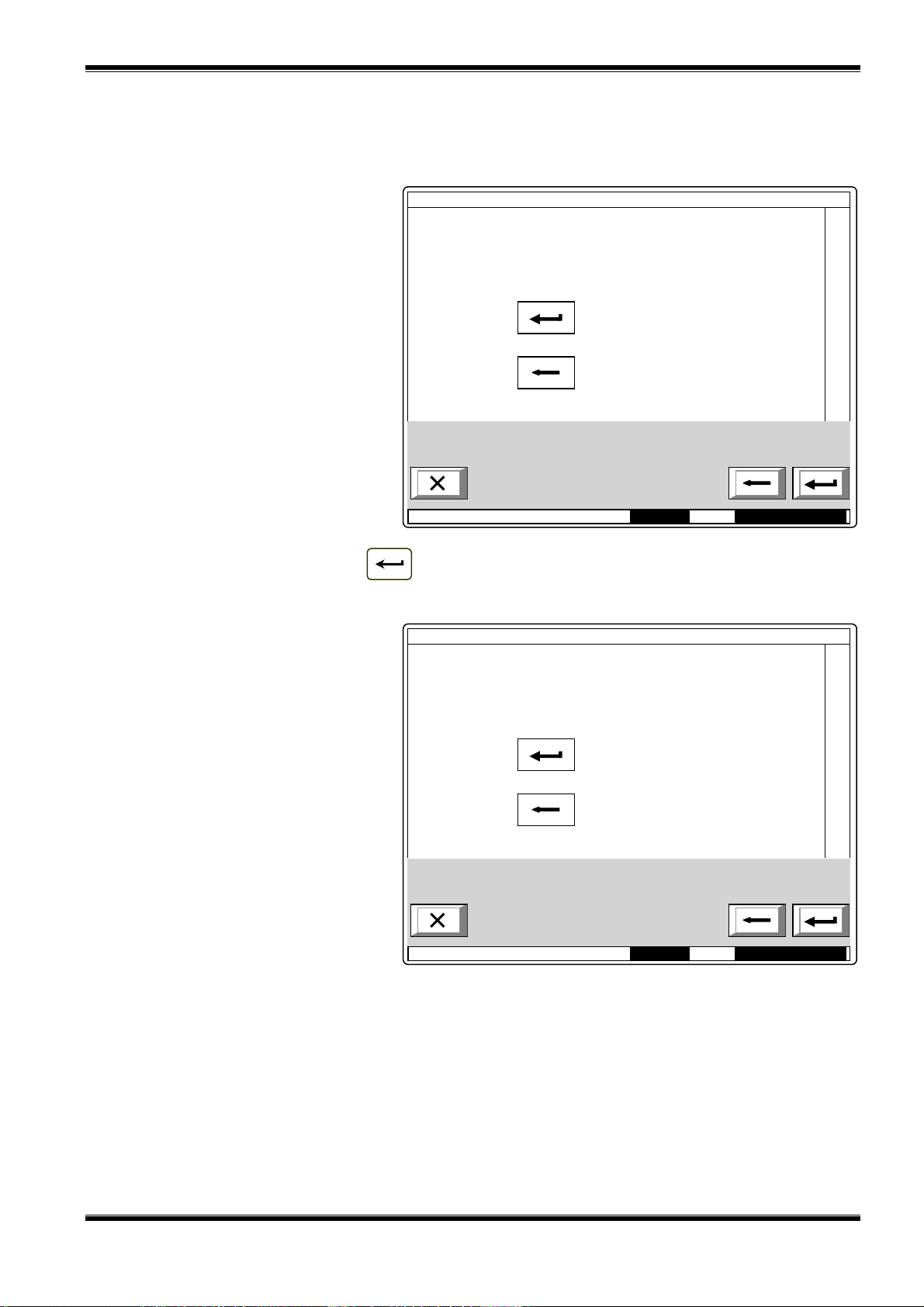
UniPOS Interactive Fire ControlPanel IFS7002
M
13:
3
25M
M
13:
3
13.7.1. Function Initialization
The function performs standard initialization of the addressable devices in the fire alarm loops.
During the operation addressable devices parameters (address, ID number, type and temperature
class) are checked against these saved in the memory of the control panel.
Upon activation of the function
the following warning screen
appears:
Initialization
Warning!
New Initialization!
– confirm
– cancel
ode:DAY
0:51 Fri 25Mar 2005
Start the initialization via button and in the bottom line of the panel appears the message
Wait please...
Upon unsuccessful initialization
appears the following screen:
Initialization
Would You like to run the Operation again?
– confirm
– cancel
ode:DAY
Operation unsuccessful!
7:24 Fri
Upon successful initialization the menu will be exited automatically.
Notes:
1. Only swithed on loops can be initialized.
2. The function is not affected by removed addressable devices, i.e. the opretaion will be
successful even when some devices are removed from the loops.
ar 2005
Instruction Manual Page 77
Revision 2.05 Of 107

UniPOS Interactive Fire ControlPanel IFS7002
M
15:
2
M
15:
2
13.7.2. Function Clean initialization
The function performs clean initialization of addressable devices in the fire alarm loops. Upon
clean initialization the addressable devices detected in the loops are being addressed consecutively,
and their parameters (ID number, type and temperature class) are being saved in the control panel.
Upon activation of the function
the following warning screen
appears:
Initialization
Warning!
Only available Devices will be saved!
– confirm
– cancel
ode:DAY
4:21 Fri 25Mar 2005
Start the initialization via button and in the bottom line of the panel appears the message
Wait please…
Upon unsuccessful initialization
appears the following screen:
Initialization
Would You like to run the Operation again?
– confirm
– cancel
ode:DAY
Operation unsuccessful!
4:47 Fri 25Mar 2005
Upon successful initialization the menu will be exited automatically.
Notes: Only swithed on loops can be initialized
Instruction Manual Page 78
Revision 2.05 Of 107

UniPOS Interactive Fire ControlPanel IFS7002
M
17:
0
M
16:
4
13.7.3. Menu Readdressing
The menu allows the user to exclude an addressable device from the service zone. Enter the
menu to display:
− If no devices are available in the service zone – a screen with the message The service Zone
is empty; the only option is to exit the menu.
− If some devices are included
in the service zone – a
screen for the selection of
device that shall be excluded
from the service zone:
For each device is displayed the
loop it is included in and its address
in the loop.
The current device is pointed by
arrow – „>>”.
Readdressing Total Devices: 015 Go to:
>> 1 Lp1 Аddr1
2 Lp1 Аddr2
3 Lp1 Аddr3
4 Lp1 Аddr4
5 Lp1 Аddr10
6 Lp1 Аddr11
7 Lp2 Аddr1
8 Lp2 Аddr2
9 Lp2 Аddr3
10 Lp2 Аddr14
11 Lp2 Аddr15
12 Lp2 Аddr16
13 Lp2 Аddr17
The field Go to in the heading
and the digit buttons are visualized if
1 2
0
3 4 5
6 7
8
9 С
more than 13 devices are available in
the service zone.
When you press a digit button,
the Go to field is activated and you
ode:DAY
4:26 Fri 25Mar 2005
can enter a random 3-digit number
for a device in the service zone. To
edit the number use button , which will delete the last digit you entered.
С
When you press button and a number is already entered in the Go to field, the device
whose number in the service zone is in the field will be selected:
− If the number is 0, the first device in the service zone will be selected;
− If the number is higher than the actual number of devices in the service zone, then the device
having the highest number in the service zone will be selected.
Simultaneously, the number in the Go to field is deleted, i.e the field is deactivated.
When you press button and a number is entered in the Go to field, the field will be
deactivated.
Readdressing Lp1 Аddr2
When you press button
and the Go to field is empty, a screen
for selection of new address for the
device appears:
As supplementary information is
visualized the address range where
the new address of the device can be
selected from.
To enter the new address use
the digit buttons. Press button to
С
New address: _
From address: 2
To address: 4
1 2
0
3 4 5
6 7
8
9 С
delete the digit to the left of the
cursor.
ode:DAY
4:39 Fri 25Mar 2005
Instruction Manual Page 79
Revision 2.05 Of 107

UniPOS Interactive Fire ControlPanel IFS7002
M
:
4
M
18:
1
If the new address is out of the
specified range, button is
ignored. Otherwise a command
screen appears where you shall
confirm the readdressing:
The following information is
displayed on the screen:
− The new address that will be
assigned to the device;
Readdressing Lp1 Аddr2
New address:3
Point 1.003
Different Device ID
Different Device Type
Differenet Device Class
Save new Data?
– confirm
– cancel
− The text message specified
for this address;
− Message Different device ID
– only when the ID number of
the device is different than
ode:DAY
3:51 Fri 25Mar 2005
the number for this address
saved in the control panel;
− Message Different device type – only when the device type is different than the type saved for
this addres in the control panel;
− Message Different device class – only when the temperature class of the device is different
than the class saved in the control panel.
When you press button the readdressing is cancelled and the screen for selection of new
address is reverted.
When you press button the readdressing is completed and the screen for selection of
devices that shall be excluded from the service zone is reverted (or the screen with the message The
service zone is empty).
13.7.4. Menu Exclude devices
The menu allows the user to
exclude or include separate
addressable devices:
All 250 (125 in each loop)
addressable devices are accessible
whether included physically to the
fire alarm loops or not. In the middle
of the heading is displayed the total
number of devices included in both
loops.
Exclude Devices Devices total: 63 Go to:
>> 1 Lp1 Аddr1
Point 1.001
2 Lp1 Аddr2
Point 1.002
3 Lp1 Аddr3
Point 1.003
4 Lp1 Аddr4
Point 1.004
5 Lp1 Аddr5
Point 1.005
6 Lp1 Аddr6
Point 1.006
For each device is displayed:
1 2
0
3 4 5
6 7
8
9 С
− Its consecutive number, the
loop it is included in and its
address in the loop – in the
top line;
ode:DAY 9
9:43 Mon 28Mar 2005
− The text message – in the
line beneath.
The devices obtain numbers according to the sequence:
− Devices in Loop 1 – numbers from 1 tо 125;
− Devices in Loop 2 – numbers from 126 tо 250.
The selected device is pointed by arrow – „>>”.
Instruction Manual Page 80
Revision 2.05 Of 107

UniPOS Interactive Fire ControlPanel IFS7002
M
10:
3
M
10:
0
When you press a digit button, the Go to field is activated and you can enter a random 3-digit
number for the device. To edit the number, press button and the last entered digit will be deleted.
С
When you press button and a number is already entered in the Go to field, the device
whose number is in the field will be selected:
− If the number is 0, Address 1 in Loop 1 will be selected ;
− If the number is higher than 250, Address 125 in Loop 2 will be selected.
Simultaneously, the number in the Go to field is deleted, i.e. the field is deactivated.
When you press button and a number is entered in the Go to field, the field will be
deactivated.
When you press button
and the Go to field is empty, a screen
for exclusion/inclusion of the
addressable device appears:
The status of the device is
displayed in inversive colours.
Change the status by pressing button
– the status is changed
Exclude Devices
Lp1 Аddr1 On
Point 1.001
alternatively from included to
excluded and vice versa.
ode:DAY
8:31 Mon 28Mar 2005
13.7.5. Menu Check
The menu is provided for check up of the initialization of addressable devices, included in the fire
alarm loops.
When you enter the menu the following operations are being run:
− If no devices are available in the loops – a screen with the message No devices appears; the
only option is to exit the menu;
− If some devices are available
in the loops – a command for
LEDs illumination is sent to
the first device, if the loops
are On and are initialized. A
screen for the device status
and for selection of the next
device for check up is
visualized:
Check Devices Total: 63 Go to:
>>Lp1 Аddr1
Point 1.001
Device is On
Successful data Transfer to the Device
1 2
0
Indicated Device:
3 4 5
6 7
8
9 d
ode:DAY
3:39 Mon 28Mar 2005
For the current device is displayed:
− The loop it is included in, and its address in the loop;
− Its text message;
Instruction Manual Page 81
Revision 2.05 Of 107

UniPOS Interactive Fire ControlPanel IFS7002
− Device status (On or Off) – it is displayed only when the loop the device is included in is On
and is initialized;
− Information for the communication with the devices:
♦ the loop is off – appears the message The loop is off (no attempt for communication
with the device has been made);
♦ the loop is On, but is not initialized – appears the message Uninitialized loop (no
attempt for communication with the device has been made);
♦ the loop is On and is initialized – as a result from communication with the device
(Successful data transfer to the device or Error in data transfer to the device).
The current device is pointed by arrow – „>>”.
When the data transfer is successful the device LEDs illuminate and indicate the physical device
having this particular address.
When you press a digit button the Go to field is activated; you can enter a random 3-digit number
for the device. To edit the number use button press it to delete the last entered digit.
The devices obtain numbers according to the following sequence: from the first device in Loop 1
to the last device in Loop 1; from the first device in Loop 2 to the last device in Loop 2.
When you press button and a number is already entered in the Go to field, the device
whose address is in the field will be selected:
− if the number is 0, the first addressable device in the control panel will be selected;
− if the number is higher than the actual number of devices in the loop, the last device in the
control panel will be selected.
At the same time:
− the number in the Go to field is deleted, i.e. the field is deactivated;
− the device that has been checked receives a command to extinguish the LEDs, if the device
loop is On and is initialized;
− the device that has been selected for check-up, receives a command to illuminate the LEDs, if
the loop is On and is initialized;
− the screen is refreshing the status of the new device.
С
When you press button and a number is already entered in the Go to field, the field is
deactivated.
When you press button and the Go to field is empty, the button effect is ignored.
Upon exit of the menu the last checked device receives command to extinguish its LEDs, if the
loop is On and is initialized.
Instruction Manual Page 82
Revision 2.05 Of 107

UniPOS Interactive Fire ControlPanel IFS7002
M
14:
3
M
14:
0
13.8. Menu Checks
The menu allows the user to set up the control panel outputs (monitored, relay and addressable),
the display and the buttons. It cointains the following submenus and functions:
− Menu Monitored outputs;
− Menu relay outputs;
− Menu Addressable outputs;
− Function Display;
− Menu Buttons.
13.8.1. Menu Monitored outputs
Using the menu you can run a check on control panel minitored outputs.
When you entere the meny
Monitored output 1 is triggered (if not
in Fault condition) and the following
screen appears:
At the activated monitored output
is displayed the message Yes, in
inversive colours; at the output not
activated yet is displayed the
Check monitored Outputs
Activated Device:
Monitored Output 1 Yes
Monitored Output 2 No
message No in general colours.
When you press button or
the activated monitored output is
switched off and the other output is
activated (if not in fault condition).
de:DAY
2:46 Mon 28Mar 2005
Upon exit of the menu the activated monitored output is switched off.
13.8.2. Menu Relay outputs
Using the menu you can run a check on the relay outputs of the fire control panel.
When you enter the menu, Relay
output 1 is activated and the
following screen appears:
At the activated relay output
appears the message Yes in
inversive colours; at the realy output
not activated yet appears the
Check relay Outputs
Activated Device
Relay Output 1 Yes
Relay Output 2 No
message No, in general colours.
When you press button or
the activated relay outputs is
switched off, and the other one is
activated.
ode:DAY
2:26 Mon 28Mar 2005
Upon exit of the menu the activated relay output is switched off.
Instruction Manual Page 83
Revision 2.05 Of 107

UniPOS Interactive Fire ControlPanel IFS7002
M
14:
4
13.8.3. Menu Addressable outputs Use the menu to check the addressable outputs of the control panel. When you enter the menu the following operations are being run:
− If no addressable outputs are available – a screen with the message No addressable outputs
appears; the only option is to exit the menu;
− If some addressable outputs
are available – a command
for activation is sent to the
first addressable output, if the
loop is On and is initialized. A
screen for the output status
and for selection of the next
output for check up is
visualized:
For the current addressable
Check addressable Outputs Go to:
Activated Device:
>>Lp1 Аddr25.1
Point 1.025
Device is On
Successful data Transfer to the Device
output is displayed:
− The loop it is included in, its
1 2
0
3 4 5
6 7
8
9 С
address in the loop and the
number of the output in the
device, if more than one
output is available;
ode:DAY
3:46 Mon 28Mar 2005
− Device text message;
− Device status (On or Off) – it
is displayed only when the loop the device is included in is On and is initialized;
− Information for the communication with the device:
♦ the loop is off – appears the message The loop is off (no attempt for communication
with the device has been made);
♦ the loop is On, but is not initialized – appears the message Uninitialized loop (no
attempt for communication with the device has been made);
♦ the loop is On and is initialized – as a result from communication with the device
(Successful data transfer to the device or Error in data transfer to the device).
The current addressable output is pointed by arrow – „>>”.
When the data transfer is successful the device output will be activated.
Buttons and in the right panel section are visualized if more than one addressable output
is available; the Go to field in the heading and the digit buttons appear if addressable outputs in more
than one device are available.
When you press a digit button the Go to field is activated; you can enter a random 3-digit number
for the device. To edit the number use button press it to delete the last entered digit.
С
The devices obtain numbers according to the following sequence: from the first device in Loop 1
to the last device in Loop 1; from the first device in Loop 2 to the last device in Loop 2.
When you press button and a number is already entered in the Go to field, the first
addressable output in the first device whose number is equal to or higher than the number in the field
will be selected:
− if the number is 0, the first addressable output will be selected;
− if the number is higher than the number of device having the last addressable output, the last
addressable output will be selected.
At the same time:
− the number in the Go to field is deleted, i.e. the field is deactivated;
− the output that has been checked receives a command to switch off, if the loop is On and is
initialized;
− the output that has been selected for check-up, receives a command for activation, if the loop
is On and is initialized;
Instruction Manual Page 84
Revision 2.05 Of 107

UniPOS Interactive Fire ControlPanel IFS7002
M
17:
1
M
15:
1
− the screen is refreshing the status of the new output.
When you press button and a number is already entered in the Go to field, the field is
deactivated.
When you press button and the Go to field is empty, the button effect is ignored.
Upon exit of the menu the last checked output receives command for deactivation, if the loop is
On and is initialized.
13.8.4. Function Display
Use the function to check the LCD display of the fire control panel.
When you enter the function the
following screen appears:
When you press button
that is in the middle of the display,
the check is being started – the
display changes its colour from black
to white and then to grey. Each
colours remains for about 4 s. After
the check is completed, the initial
Check Display
You must see:
black, white and grey display
To start the Check
push button
screen appears.
ode:DAY
2:16 Mon 28Mar 2005
13.8.5. Menu Buttons
The menu is used for check-up and set up of the buttons situated on the LCD display of the
control panel.
Enter the menu to display:
Check Buttons
- Exit - SetUp
1 2
0
ode:DAY
Push a button
3 4 5
6 7
1:22 Mon 28Mar 2005
8
9 С
Instruction Manual Page 85
Revision 2.05 Of 107

UniPOS Interactive Fire ControlPanel IFS7002
M
17:
4
M
17:
2
M
17:
2
When a random button is
pressed (except for buttons ,
and ) a message and a
graphic image of the presses button
appear:
To start setting the buttons up,
press button . Set up is being
performed at two points on the
display and is being checked at a
third point. Enter the function to
display the first point of set up:
The point of intersection – a
cross – shall be pressed by the
means of small-size round tip
pointer. For point two and point three
goes the same.
Check Buttons
- Exit - SetUp
Pushed button
1 2
0
ode:DAY
+ Push the Point of intersection
Push a button
3 4 5
5
6 7
1:09 Mon 28Mar 2005
8
9 С
ode:DAY
6:07 Mon 28Mar 2005
If the check performed at the
third point is successful, the function
is exited automatically. Otherwise a
screen with error message appears:
Would You like to run the Operation again?
– confirm
– cancel
ode:DAY
Operation unsuccessful!
8:15 Mon 28Mar 2005
The check-up can be interrupted at any stage by pressing button or .
Instruction Manual Page 86
Revision 2.05 Of 107

UniPOS Interactive Fire ControlPanel IFS7002
M
18:
4
5
M
18:
2
13.9. Menu New passwords
The menu allows the user to compose and edit passwords for Access Level 2 and Access Level
3. It contains:
− Menu Level 2;
− Function Level 3.
13.9.1. Menu Level 2
The menu allows the user to enter and edit passwords for Access Level 2.
Enter the menu and a screen
where you can edit the first password
for Access Level 2 appears:
To enter or edit a password use
the digit buttons – when you press a
button, the digit is inserted over the
position of the cursor, and the
previous text and the cursor move
one position to the right.
Move the cursor to the left or to
PASSWORD Level 2
New Password 1: 1111_
the right using buttons and .
Press to delete:
С
1 2
0
3 4 5
6 7
8
9 С
− The digit under the cursor, if
any;
− The digit to the left of the
ode:DAY
4:10 Mon 28Mar 2005
cursor, if no digit is available
under the cursor.
The maximum length of the password is 10 symbols. If you press a button after the 10-digit
password is entered, the exceeding symbol will not be accepted.
When you press button the last entered password will be saved in the control panel.
When you press button or the previous or the next password will be displayed for edition.
Any unsaved passwords will be lost.
13.9.2. Function Level 3
The function allows the user to
enter and edit a password for Access
Level 3:
To enter or edit a password use
the digit buttons – when you press a
button, the digit is inserted over the
position of the cursor, and the
previous text and the cursor move
one position to the right.
Move the cursor to the left or to
PASSWORD Level 3
New Password: 1091_
the right using buttons and .
Press to delete:
С
1 2
0
3 4 5
6 7
8
9 С
− The digit under the cursor, if
any;
− The digit to the left of the
ode:DAY
4:51 Mon 28Mar 200
cursor, if no digit is available
under the cursor.
Instruction Manual Page 87
Revision 2.05 Of 107

UniPOS Interactive Fire ControlPanel IFS7002
M
:
4
M
:
4
The maximum length of the password is 10 symbols. If you press a button after the 10-digit
password is entered, the exceeding symbol will not be accepted.
When you press button the last entered password will be saved in the control panel.
13.10. Function Default parameters
The function saves the default parameters of the control panel.
Upon activation the following
screen appears:
Default Parameters
Warning!
Default Parameters will be saved!
– confirm
– cancel
ode:DAY 9
1:49 Tue 29Mar 2005
To save the record press button , in the bottom line of the panel appears the message Wait
please…
Upon unsuccessful operation
appears the following screen:
Default Parameters
Would You like to run the Operation again?
– confirm
– cancel
ode:DAY 9
Operation unsuccessful!
3:50 Tue 29Mar 2005
When the records are successfully saved, the menu is exited automatically.
The following default parameters are being saved:
− Control panel parameters:
♦ Local network – none;
♦ Periphery module 1 – none;
♦ Periphery module 2 – none;
♦ Periphery module 3 – none;
♦ Number of zones – 0;
♦ Language– English;
Instruction Manual Page 88
Revision 2.05 Of 107

UniPOS Interactive Fire ControlPanel IFS7002
M
10:
3
♦ Mode of operation – DAY;
− Loop 1 parameters:
♦ The loop is On;
♦ Number of devices in the loop – 0;
♦ Maximum current in the loop – 120mA;
− Loop 2 parameters:
♦ The loop is off;
♦ Number of devices in the loop – 0;
♦ Maximum current in the loop – 120mA;
− Power loop – off;
− Zone 1-250 parameters:
♦ Manual call point priority – yes
♦ Coincidence Mode – no;
♦ Time Fire Phase 1 - Phase 2 – 120s;
♦ Inspection time – 120s;
♦ Number of devices in the zone – 0 (free zone);
♦ Fire Phase 1 outputs – none;
♦ Fire Phase 2 outputs – none;
− Device parameters (Addresses 1 tо 125 in Loop 1 and addresses 1 tо 125 in Loop 2)
♦ Zone – 255 (not included in a zone);
♦ Device is On;
− Addressable input parameters (Addresses 1 to 125 in Loop 1 and addresses 1 to 125 in
Loop 2):
♦ Text message – none;
♦ Activated inputs – none;
− Disables:
♦ zone – none;
♦ devices – none;
♦ outputs – none;
− Zones in test – none.
13.11. Function Clear archive
The function is provided for deleting the control panel archive.
Upon activation the following
warning screen appears:
Clear Archive
Archive will be deleted!
– confirm
– cancel
ode:DAY
Warning!
6:15 Tue 29Mar 2005
To start deleting the archive press button , in the bottom line of the panel appears the
message Wait please…
Instruction Manual Page 89
Revision 2.05 Of 107

UniPOS Interactive Fire ControlPanel IFS7002
M
10:
3
Upon unsuccessful operation
appears the following screen:
Clear Archive
Would You like to run the Operation again?
– confirm
– cancel
ode:DAY
Operation unsuccessful!
8:08 Tue 29Mar 2005
Upon successful operation the menu will be exited automatically.
14. Remote Control Mode
14.1. Description
The control panel enters Remote Control Mode when an external control device of higher level
(computer from a centralized Dispatcher Control Point or similar) performs set up of the control panel
configuration parameters via serial interface. All other modes and condition are exited. When in
Remote Control Mode the panel does not provide service to fire alarm zones, addressable devices,
monitored outputs and other periphery devices (all outputs are off); it is under the control of the
external device. Upon exit of Remote Mode reset of the control panel is performed.
14.2. Indication
14.2.1. LED and sound indication
In Remote Mode only the green LED indicator is illuminated (Power supply). The local
sounder is off.
14.2.2. Тext messages
The following screen appears on
the LCD display:
Remote control
14.3. Keypad
In Remote Mode none of the buttons are active.
Instruction Manual Page 90
Revision 2.05 Of 107

UniPOS Interactive Fire ControlPanel IFS7002
15. Saving the parameters
All set values for parameters or modes of operation are being saved in the energy independent
memory and upon interruption of mains supply or backup batteries supply the values remain intact.
After the control panel is switched on again, it starts operation in accordance with values and modes
previously set.
Default parameters and modes of operation are factory set up (see section.
User passwords are set to:
− Access Level 2 passwords:
♦ Password 1 – 1111;
♦ Password 2 – 2222;
♦ Password 3 – 3333;
♦ Password 4 – 4444;
♦ Password 5 – 5555;
♦ Password 6 – 6666;
♦ Password 7 – 7777;
♦ Password 8 – 8888;
♦ Password 9 – 9999;
♦ Password 10 – 1010;
− Access Level 3 password - 0000.
16. Labour protection requirements
13.10).
The installation and maintenance staff shall be well grounded in equipment’s mechanism and
operation, as well as in common technical safety regulations.
Connection to unearthed or to indirectly earthing mains supply is prohibited.
Troubleshoots are to be cleared after disconnecting the feeding cable from the mains supply.
The control panel is designed for installing in premises with a normal fire hazard, as per the Fire
Precaution Technical Regulations in Building Construction.
17. Installation and arrangements
When fire detectors and periphery devices are integrated in the system, avoid arranging wires in
closed loops; it will reduce the control panel’s resistance to electro magnetic interferences
17.1. To mount the fire control panel
− Unpack the device;
− put the dowels on the determined places;
− fasten the control panel to the dowels through the three holes provided on the chassis.
17.2. Periphery devices assembly
All connections are to be made by means of terminals, mounted on the printed circuit board 7002
Main (Appendix 4). Be advised, that the total consumption of the voltage powering the external
devices (terminal “+ 28V”) plus the consumption of the monitored outputs shall not exceed 1.5A in
heavy duty mode.
17.2.1. Mounting periphery devices to monitored outputs
Terminals “+Out1”, “-Out1”, “+Out2”, “-Out2” – monitored potential outputs, responding upon Fire
condition (depending on the pre-programmed relation fire alarm line – monitored outputs) are to be
used.
Use the special connection diagram for the executive device provided in Appendix 6a.
End of line resistors 5k6 are connected directly to the terminals of the unused monitored outputs.
17.2.2. Mounting periphery devices to relay outputs
The following terminals are used:
− Terminal “+28V” – positive lead of the stabilized direct current supplying the external devices
(light and sound signaling devices, executive devices and others);
− Terminal “GND” – chassis ground (negative lead of the stabilized direct current supplying the
external devices);
Instruction Manual Page 91
Revision 2.05 Of 107

UniPOS Interactive Fire ControlPanel IFS7002
− Terminals “Rel1/C”, “Rel1/NO”, “Rel1/NC”, “Rel2/C”, “Rel2/NO” and “Rel2/NC” – potential free
relay contacts, responding at Fire condition (in compliance with the pre-programmed relation
fire alarm line – relay outputs);
− Terminals “REL Fault/C”, “REL Fault/NO” and “REL Fault/NC” – potential free relay contacts.
When no fault condition is detected terminals “REL Fault/C” and “REL Fault/NO” are
connected; upon detection of fault condition terminals “REL Fault/C” and “REL Fault/NC” are
connected.
The executive device shall be connected according to Appendix 6b.
Unused relay outputs remain unoccupied.
17.3. Connecting interface devices
17.3.1. Global network
Connection of interface devices to the global network is made via serial interface RS232, using 9-
lead coupling (Appendix 4). Signals distribution is given in
Coupling’s lead Signal of RS232 Interface Signal of RS485 Interface
2 RXD (input data) Inverting input/output
3 TXD (output data) Non inverting input/output
4 DTR
5 GND (chassis ground)
The fire control panel provides power supply to an external modem, if the feature has been
included in the customer’s order. The power supply is tapped on a two-pole terminal on the PCB
Power supply to modem.
Table 3.
Table 3
17.3.2. Local network
Connection of interface devices to a local network is made via two serial interfaces CAN 2.0B
using the terminals CAN1 and CAN2.
17.4. Connecting addressable fie detectors
Addressable fire detectors are connected to the fire control panel by means of two-wire insulated
line of total resistance up to 100Ω (Appendix 5a). Connection is made to the terminals of the
corresponding fire alarm loops (Appendix 4) observing the indicated polarity (N is the number of othe
loop).
− “+LoopN-1”, “-LoopN-1” and „
− “+LoopN-2”, “-LoopN-2” and „
In one fire alarm loop a maximum of 125 addressable devices can be included regardless of their
type.
Unused fire alarm loops remain free (no connection is made to their terminals).
It is recommended to include addressable devices in closed fire alarm loops (Appendix 5b). If
branches of the loop (Apendix 5c) are to be used, the following restrictions shall be observed:
− do not connect a branch between the control panel and the first/last device in the loop
(Appendix 5d);
− do not connect two or more branches between two consecutive devices in a loop (Appendix
5e).
Addressable output modules supplied by the power loop shall be connected to it by means of twowire insulated line of total resistance not more than 10Ω (Appendix 5a). Connection is made to the
terminals of the power loop (Appendix 4) observing the indicated polarity:
− “+PowerL-1” and “-PowerL-1” for the beginning of the loop;
− “+PowerL -2” and “-PowerL -2” for the end of the loop.
:” for the beginning of the loop;
:” for the end of the loop.
Instruction Manual Page 92
Revision 2.05 Of 107

UniPOS Interactive Fire ControlPanel IFS7002
17.5. Power supply connection Take out the fuse from the terminal with mains fuse (Appendix 3). Connect a feeding cable to the terminal with mains fuse, observing the following positions
(Appendix 3):
− P – power wire “Phase”;
− N – power wire “Null”;
: - safety ground wire.
−
The cable shall be double insulated and of 0,5mm
1,5mm
2
section for the safety ground wire.
2
section for the power supply wires, and of
The other end of the feeding cable is connected to the mains power supply by means of junction
box.
The mains power supply of the fire control panel shall be in a separate loop.
18. Fire control panel start up
Make sure that the connection to mains power supply is properly made.
Make sure that the periphery devices are correctly connected.
Place the fuse in the terminal with mains fuse, the display illuminates and appears the text
System operations.
Connect the feeding cable and the backup batteries; the batteries shall be in a series connection.
Connect the red wire to the positive backup battery pole, and the blue wire - to the negative pole.
The overall voltage of both batteries shall not exceed 17.6V, otherwise the fire control panel will not
recognize them.
Enter SetUp Mode and configure the control panel as follows:
1. Save the default parameters (except for a control panel with factory set up parameters) –
Function Default parameters (see section 13.10);
2. Select a language for the messages –
3. Set the loop parameters –
Menu Loop parameters (see section 13.4.1):
Menu Panel configuration (see section 13.2);
♦ Loop status – On or Off;
♦ Maximum current in the loop;
4. Exclude all unused devices in the loops, if any –
5. Start clean initialization of the addressable devices in the loops –
(see section
13.7.2);
6. Run a check on the initialization of the addressable devices in the loops –
section
13.7.5);
Menu Exclude devices (see section 13.7.4);
Function Clean initialization
Menu Check (see
7. If the configuration of any of the loops does not cover your requirements, rearrange the
addressable devices and repeat operations 4 – 6 set herein (regarding section 4, be advised
that you might need to include devices);
8. Entera text message for each addressable device in the loop –
(see section
9. Form fire alarm zones and set their parameters up –
♦ Devices in the zone –
♦ Аoutputs associated to the zone –
13.4.2);
Outputs (see section
Menu Zones (see section 13.5):
Menu Devices (see section 13.5.1);
Menus Fire Phase 1 Outputs and Fire Phase 2
13.5.2);
Menu Device parameters
♦ Zone parameters: Manual call point priority, Coincidence mode, Time Fire Phase 1 –
Phase 2 and Inspection Time –
♦ Тtext message for the zone –
10. Set up parameters of any addressable inputs –
11. Activate the power loop if necessary –
12. Enter the passwords for Access Level 2 and Access Level 3 –
section
13. Clear the archive –
13.9);
Function Clear archive (see section 13.11).
Menu Zone parameters (see section 13.5.3);
Screen Text message (see section 13.5.4);
Menu Inputs (see section 13.6);
Menu Panel configuration (see section 13.2);
Menu New passwords (see
Upon exit of SetUp Mode the control panel runs again System operations and enters Duty Mode
– the fire controlpanel is ready to provide site protection.
19. Troubleshooting
Possible problems and methods of troubleshooting are described in
Table 4.
Instruction Manual Page 93
Revision 2.05 Of 107

UniPOS Interactive Fire ControlPanel IFS7002
Table 4
Trouble Indication Troubleshooting
Fatal system error
Low backup batteries
due to interrupted
mains power supply
Short circuit or Open
loop
Activated isolator of
addressable device
Fault condition
Uninitialized loop
Fault Exceeding
number of devices in
the loop, Uninitialized
device, Exchanged
devices, Different ID
number of device,
Different device type,
Different device
temperature class
Fault Removed device
Fault Communication
error with the device or
Fault in device
Fault Contaminated
sensor (only in
detectors with opticalsmoke part)
Indicators and illuminate in
steady yellow light; the local sounder
releases continuous signal
The local sounder releases
discontinuous signal (1s sound, 3s
break); the message Battery Low
appears on the screen; the backlight of
the display is off
Indicator flashes in yellow light;
the local sounder releases discontinuous
signal; information table with the number
of faults appears on the display
Indicator flashes in yellow light;
the local sounder releases discontinuous
signal; information table with the number
of faults appears on the display
Indicator flashes in yellow light;
the local sounder releases discontinuous
signal; information table with the number
of faults appears on the display
Indicator flashes in yellow light;
the local sounder releases discontinuous
signal; information table with the number
of faults appears on the display
Indicator flashes in yellow light;
the local sounder releases discontinuous
signal; information table with the number
of faults appears on the display
Indicator flashes in yellow light;
the local sounder releases discontinuous
signal; information table with the number
of faults appears on the display
Indicator flashes in yellow light;
the local sounder releases discontinuous
signal; information table with the number
of faults appears on the display
The trouble shall be fixed in
Technical Service and
Maintenance Department
Restore the mains power supply
or replace the backup batteries
Eliminate the fault (short circuit
or open loop)
Eliminate the fault (short circuit
in the loop)
- Eliminate the fault (open loop);
- Restore the loop so it complies
with the configuration saved in
the controlpanel and start
initialization of the control panel;
- Start clean initialization of the
control panel
- Restore the loop so it complies
with the configuration saved in
the controlpanel and start
initialization of the control panel;
- Start clean initialization of the
control panel
Instal the device
Repair or replace the device (if
you replace the device then run
clean initialization of the control
panel)
Remove the detector and clean
the optical part and place it
again.
Instruction Manual Page 94
Revision 2.05 Of 107

UniPOS Interactive Fire ControlPanel IFS7002
Table 4 continued
Trouble Indication Troubleshooting
Fault in monitored
output
Fault in mains supply
Fault in backup
batteries supply
Fault in supply to
external devices
Short circuit to
grounded wire
Fault in internal supply
devices
Indicator flashes in yellow light;
the local sounder releases discontinuous
signal; information table with the number
of faults appears on the display
Indicators and are
illuminated in steady yellow light; the
local sounder produces discontinuous
signal; information table with the number
of faults appears on the display
Indicators and are
illuminated in steady yellow light; the
local sounder produces discontinuous
signal; information table with the number
of faults appears on the display
Indicator flashes in yellow light;
the local sounder releases discontinuous
signal; information table with the number
of faults appears on the display
Indicator flashes in yellow light;
the local sounder releases discontinuous
signal; information table with the number
of faults appears on the display
Indicator flashes in yellow light;
the local sounder releases discontinuous
signal; information table with the number
of faults appears on the display
- Eliminate the fault (short circuit
or break) in the line of the
monitored output or of the
executive device;
- Upon break check for a shortcircuited element in the
monitored output to a grounded
wire (see also Short circuit to
grounded wire)
- Restore the mains supply;
- Replace the 4A fuse with
mains fuse (Appendix 3)
- Place or change the backup
batteries
- Replace the burnt fuse 4А
Eliminate the overload to the
supply of the external devices
Eliminate the short circuit
The trouble shall be fixed in
Technical Service and
Maintenance Department
Instruction Manual Page 95
Revision 2.05 Of 107

UniPOS Interactive Fire ControlPanel IFS7002
20. Conditions of operation, storage and transportation
20.1. Operation and storage
The fire control panel shall operate and be kept in closed premises, under the following
conditions:
20.1.1. Temperature
− storage - from +5 tо +35°C
− transportation - from -10 tо +50°C
− operational - from -5°С tо +40°С
20.1.2. Relative humidity
− storage - tо 80%
− operational - tо 93%
20.2. Transportation
The fire control panel shall be transported by vehicles, in factory packing, in the above stated
environmental conditions and at sinusoidal vibrations with accelecartion amplitude not more than
4,9m/s
2
in frequency range 10 to 150Hz.
21. Warranty
The producer guarantees compliance of the device with BDS EN 54-2: 1997. The warrant period
is 18 months from the date of the purchase, providing that
− the conditions of storage and transportation have been observed;
− the startup has been done by authorized personnel only
− the requirements for operation stated herein have been observed.
UniPOS wishes you a successful work!
Instruction Manual Page 96
Revision 2.05 Of 107

UniPOS Interactive Fire ControlPanel IFS7002
1234567
8
22. Appendixes Appendix 1
1 Common indicator for fire condition
2 Common indicator for fault condition
3 Indicator for System error
4 Indicator for Fault in power supply
5 Indicator for Disabled component
6 Test indicator
7 Indicator for Power supply
8 LCD display
Front panel of IFS7002
Instruction Manual Page 97
Revision 2.05 Of 107

UniPOS Interactive Fire ControlPanel IFS7002
Appendix 2
Duty Mode Fire condition
Lists System functions
Faults
Disables
Test
Control panel
configuration
Control panel
parameters
Loops
Automatically
Main screen
Total
Zones
Devices
Outputs
Total
Zones
Devices
Outputs
Zones
Status of
zones
Loop1
Loop2
Password Level 2
Disables
Zones in
test
Real time
clock
Mode of
operation
Check LEDs and
Buzzer
Loop parameters
Device parameters
Loop parameters
Device parameters
SetUp
Password Level 3
Appendix 2b
Zones
Devices
Outputs
Zones
Status of
devices
Inputs
Archive
Select a
zone
Total
Fire conditions
Faults
Period
Devices
Fire Phase 1
Outputs
Fire Phase 2
Outputs
Zone parameters
After date
Before date
Between dates
Control panel outputs
Addressable outputs
Control panel outputs
Addressable outputs
а) Main menu
Instruction Manual Page 98
Revision 2.05 Of 107
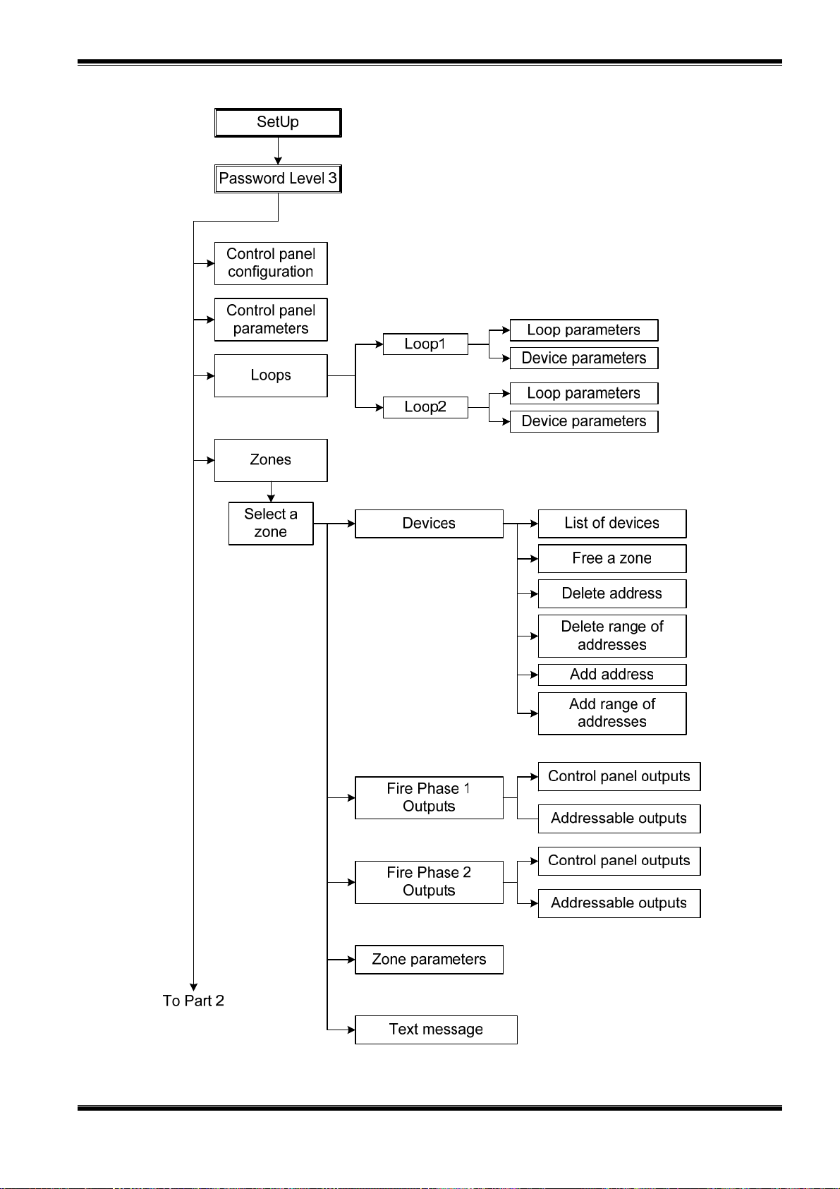
UniPOS Interactive Fire ControlPanel IFS7002
Appendix 2 continued
b) SetUp menu (part 1)
Instruction Manual Page 99
Revision 2.05 Of 107

UniPOS Interactive Fire ControlPanel IFS7002
Appendix 2 continued
b) SetUp menu (part 2)
Instruction Manual Page 100
Revision 2.05 Of 107
 Loading...