


UniPOS Repeater FS5200R
REPEATER FS5200R
OPERATION MANUAL
Instruction Manual Page1
Revision 3/01.17 of 48

UniPOS Repeater FS5200R
Instruction Manual Page 2
Revision 3/01.17 of 48
CONTENTS
1. Introduction ........................................................................................................................ 3
2. Function ............................................................................................................................. 3
3. Technical data.................................................................................................................... 3
4. Contents of delivery ........................................................................................................... 4
5. General information ........................................................................................................... 5
6. Duty Mode ......................................................................................................................... 9
7. Fire condition ................................................................................................................... 10
8. Fault Condition ................................................................................................................. 13
9. Disabled Component........................................................................................................ 17
10. Information and Control Mode ........................................................................................ 19
11. Labour protection requirements...................................................................................... 35
12. Installation ...................................................................................................................... 36
13. Repeater start up ........................................................................................................... 41
14. Conditions of operation, storage and transportation ....................................................... 42
15. Warranty ........................................................................................................................ 42
16. Appendix 1 ..................................................................................................................... 43

UniPOS Repeater FS5200R
Instruction Manual Page 3
Revision 3/01.17 of 48
1. Introduction
Repeater FS5200R is a unit supplementing the range of 5000 series products expanding the
possibilities of the fire detecting and fire extinguishing systems built on the basis of fire control
panels FS5100, FS5200, FS5200E and FS4000.
Some of its main features and possibilities are:
Indicates Fire condition and/or Fault condition occurred in each of the fire control panels
connected to it;
control effect on the connected fire control panels that have sent a signal for Fire
condition;
user oriented menu dialogue for easy and convenient operation;
four-line LCD for visualization the different modes of the repeater;
LEDs and sound indication of the operation modes;
user oriented test modes allowing for a total control of the site protected;
energy independent archive memory saving the event type, date and time,;
2. Function
Repeater FS5200R:
- receives data for Fire condition from the remote fire control panels:
- receives data for Fault condition from the remote fire control panels:
- displays information for the condition of remote fire control panels;
- executes control commands to lines of remote fire control panels for their forced exit of Fire
condition;
Repeater FS5200R could be used:
- when the persons whom are expected to detect and react initially to the fire condition
and/or fault condition signals are at a different place from the location of the fire control
panel/s;
- when fire control panels located at different sites have to be monitored and controlled
from one place;
- when the fire control panel/s are monitored from several locations.
It is compatible with FS4000, FS 5100, FS 5200, FS 5200E and FS5200R.
3. Technical data
3.1. Functional characteristics
- Connection of maximum 15 remote fire control panels (repeaters) to one
repeater;
Built-in sounder for fire condition – one tonal, discontinuous, can be switched
off
Built-in sounder for fault condition – one tonal, discontinuous, can be switched
off

UniPOS Repeater FS5200R
Instruction Manual Page 4
Revision 3/01.17 of 48
Built-in real time clock
- Interfaces for communication with the fire control panels RS485 connected to it;
- Option to prolong the time period for Fire condition stage I with programmable
inspection period
- Possibility for delay when switching the outputs for Fire alarm;
- Energy independent archive – up to 100 events;
- Operation with a wide range of output devices;
3.2. Indications of registered events
- Light indication – LED
- Text messages – LCD display, 4 lines 20 characters per line, Cyrillic letters
- Sound signaling – built-in sounder
3.3. Monitored outputs
type – potential
electrical characteristics - (245)V DC / 1A
3.4. Relay output for general function
type – potential free, switching
electrical characteristics – 3A/125ADC; 3A/30VDC
3.5. Relay output for fault condition
type – potential free, switching
electrical characteristics – 3A/125ADC; 3A/30VDC
3.6. Power supply
3.6.1. Mains
voltage – 220/230 VAC
frequency – 50 Hz
3.6.2. Back up batteries
battery type – lead, gel electrolyte
number of batteries – 2 pcs
connection – consecutive
nominal voltage of the connected back up batteries – 24 V DC
nominal capacity С20 – (1,2 – 4,5) Ah
extreme discharge voltage – 17,6V
charge voltage – 28V
3.6.3. Fuses
mains 220/230 V – 4,0 А
back up batteries – 2,0 А
3.7. Dimensions and weight of the unit
dimensions – 313 х 218 х 85 mm
weight (batteries not included) – 1,6 kg
4. Contents of delivery
Repeater FS5200R - 1 pc
Resistor 5,6 k - 2 pcs
Jumper for backup batteries - 1 pc

UniPOS Repeater FS5200R
Instruction Manual Page 5
Revision 3/01.17 of 48
Fuse 4А - 1 pc
Fuse 2А - 1 pc
Instruction manual - 1 pc
Instructions for authorized staff - 1 pc
Packing - 1 pc
5. General information
5.1. Access levels
Four access levels are available in the repeater:
5.1.1. Access Levels 1 and 2
All persons who would presumably find out and react to alarm upon fault condition or fire
condition have access to level 1 and 2. They shall be trained and authorized to operate the
repeater in the following conditions: Duty Mode, Fault condition; Disabled component and
System functions (except SetUp).
The following actions are accessible:
Displaying suppressed messages for Fire condition, Fault condition, Disabled
components and Zone in test
Forced proceeding from phase Fire condition stage I to phase Fire condition stage II
Suppressing the local sounder
Displaying the status of the connected fire control panels and repeaters;
Switching off the outputs, activated upon fire condition;
Exit of Fire condition; SetUp Mode
System functions of the fire control panel, except
5.1.2. Access Level 3
To access this level:
- unlock and open the front cover of the repeater;
- enter a password.
For the personnel authorized to have Access Level 3, it is available
- all features accessible at Level 1 and 2;
- reconfiguration of specific data of the repeater;
- replacing a burnt fuse;
- connecting executive devices;
- connecting slave fire control panels and repeaters;
- maintenance of the repeater.
5.1.3. Access Level 4
Accessible for personnel trained and authorized by the Producer to repair the repeater and to
modify the software
5.2. Conditions and indication
The repeater FS5200R operates in six basic modes: Duty Mode, Fire Condition, Fault
Condition, Disabled Component Mode, Information and Control Mode and SetUp Mode:

UniPOS Repeater FS5200R
Instruction Manual Page 6
Revision 3/01.17 of 48
Conditions of the repeater
Indication
All conditions -
The repeater is power supplied
- indicator Power supply –
continuous green light [12]
- indicator for inspection time (if
programmed) [13]
Fire condition
- common indicator Fire condition -
red light; [19]
- individual LED indicator for the
slave fire control panel (repeater)
[21]
- indicator for inspection time (if
programmed) [13]
- indicator Power supply –
continuous green light [12
Fault condition All faults except for Battery Low
- Common indicator Fault condition
– continuous yellow light [1]
- Fault condition in a remote fire
control panel [4]
Fault condition – System error
Indicator System error –
continuous yellow light [2]
Fault condition
Indicator Fault in mains supply of
the remote fire control panel continuous yellow light [5]
Fault condition
Common indicator Fault in fire
detecting line of a remote fire
control panel - continuous yellow
light [6]
Duty Mode - the repeater is in Duty Mode, when the fire control panels connected to it are
not in any of the rest five possible conditions and they have a connection with ;
Fire condition – The repeater enters Fire condition when a fire detector is activated in a
line/lines of the fire control panel connected to it;
Fault condition – the repeater enters this condition when a fault in any of the fire control
panels connected to it is registered or its connection with any of the fire control panels has
been interrupted;
Disabled component - the repeater enters Disabled component after a manual operation,
disabling a certain component has been performed –monitored output;
Information and Control;
SetUp Mode – the repeater enters SetUp Mode after activation of submenu Set up, in
Information and Control Mode;
In any moment the repeater can be in any of the above conditions/modes, or in a random
combination of Fire condition, Fault condition, Disabled component and Information and Control
mode.
Duty Mode and SetUp Mode can not be combined with another mode:
the repeater enters Duty Mode after all other conditions are exited;
when the repeater enters SetUp Mode it exits all other conditions.
The conditions of the repeater and their corresponding indication are shown in Table 1.

UniPOS Repeater FS5200R
Instruction Manual Page 7
Revision 3/01.17 of 48
Conditions of the repeater
Indication
Fault condition
Indicator Fault in monitored output
of a remote fire control panel
- continuous yellow light [7]
Fire condition
Local sounder – discontinuous signal: 0.5 s
sound, followed by 0.5s break
Fault condition –
All faults except for Battery Low
Local sounder – discontinuous signal: 1 s
sound, followed by 1 s break
Fault condition Low battery
Local sounder – discontinuous signal: 1 s
sound, followed by 3 s break
Means of control
Condition of the repeater
operation
Button Reset
Fire condition
Control operation, to force a line of the
remote fire control panel to exit Fire
condition (reset line) [14]
Button Menu
Duty mode, Fault condition
Information and Control
mode, SetUp mode and Fault
condition
To enter the menu for review, setting up
the repeater [8]
Button Down
Duty mode, Fault condition
Information and Control
mode, SetUp mode and Fault
condition
To display in the text screens the next
message or element of the menu [9]
Button Up
Duty mode, Fault condition
Information and Control
mode, SetUp mode and Fault
condition
To display in the text screens the next
message or element of the menu [10]
Button Exit
Duty mode, Fault condition
Information and Control
mode, SetUp mode and Fault
condition
To exit the menus or to exit SetUp mode
with saving the changes [11]
Button Alarm
Fault condition, Fire condition
To suppress the local sounder [15]
Button Outputs
Fire condition
- Upon activated outputs for fire condition
– to suppress the outputs;
- If no outputs for fire condition are
activated – to activate the suppressed
outputs, if any [17]
5.3. Means of control and indication
UniPOS Repeater FS5200R
Instruction Manual Page 8
Revision 3/01.17 of 48
1 2
3
4
5 6
7
8 9
10
11 121314
15
1
2
3
4
5
6
7
13
14
15
16
17
18
19
20
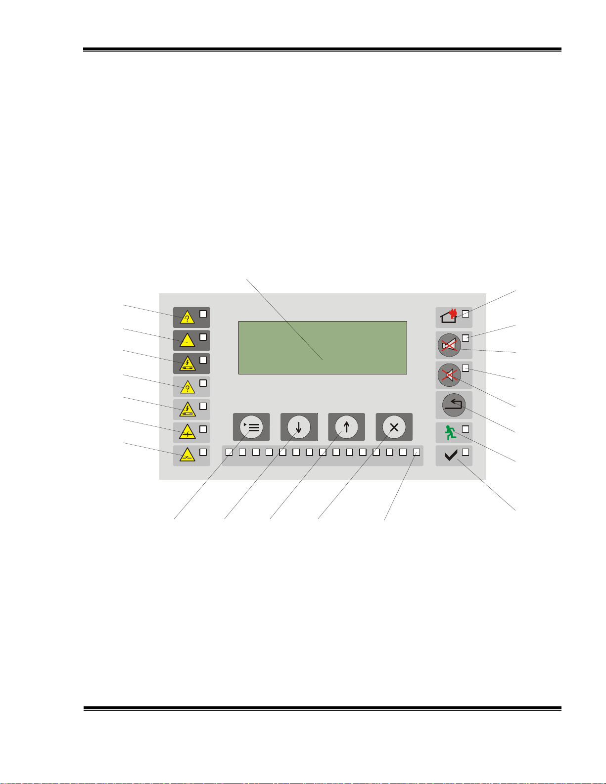
5.4. Panel for control and indication
LED indicators and buttons are positioned in functional groups, as follows:
Indicators for common fault conditions - [1], [2] and [3];
Indicators for fault conditions in the remote fire control panels (repeaters) – [4], [5], [6]
and [7];
Buttons for control on the LCD display and for entering of parameters – [8], [9], [10]
and [11];
Individual indicators for Fire condition and Fault condition of remote fire control
panels – [21];
Buttons and indicators showing each status of the repeater – [12], [13], [14], [15],
[16], [17], [18] and [19].
Front panel of repeater FS5200R
1 Common indicator for Fault condition
2 Indicator for System error
3 Indicator for Fault in power supply
4 Common indicator for Fault condition in a remote fire control panel
5 Common indicator for Fault in power supply in a remote fire control panel
6 Common indicator for Fault condition in fire detecting line of a remote fire control panel
7 Common indicator for Fault condition in monitored output of a remote fire control panel
8 Buttons Menu
9 Button Down

UniPOS Repeater FS5200R
Instruction Manual Page 9
Revision 3/01.17 of 48
The display shows:
a message “Fire protect”,
i.e. the fire control panel
is in Duty Mode;
the current local time;
the day of the week;
the current date.
1 2 3 4
5 6 7 8 9 10
11 12
13
14
15
10 Button Up
11 Button Cancel
12 Indicator Power supply
13 Indicator Delay of the outputs for Fire condition of the repeater
14 Button Reset
15 Button Alarm with indicator Suppressed alarm
16 Indicator Suppressed alarm
17 Button Outputs with indicator Suppressed outputs
18 Indicator Suppressed outputs
19 Indicator for Fire stage
20 LCD display (4х20)
21 Individual indicators for Fire condition and Fault condition in the remote fire control
panels.
6. Duty Mode
6.1. Description
The repeater is in Duty Mode when:
- it is not in Fault condition;
- the connected to it remote fire control panels (repeaters) are not in Fire
condition or Fault condition.
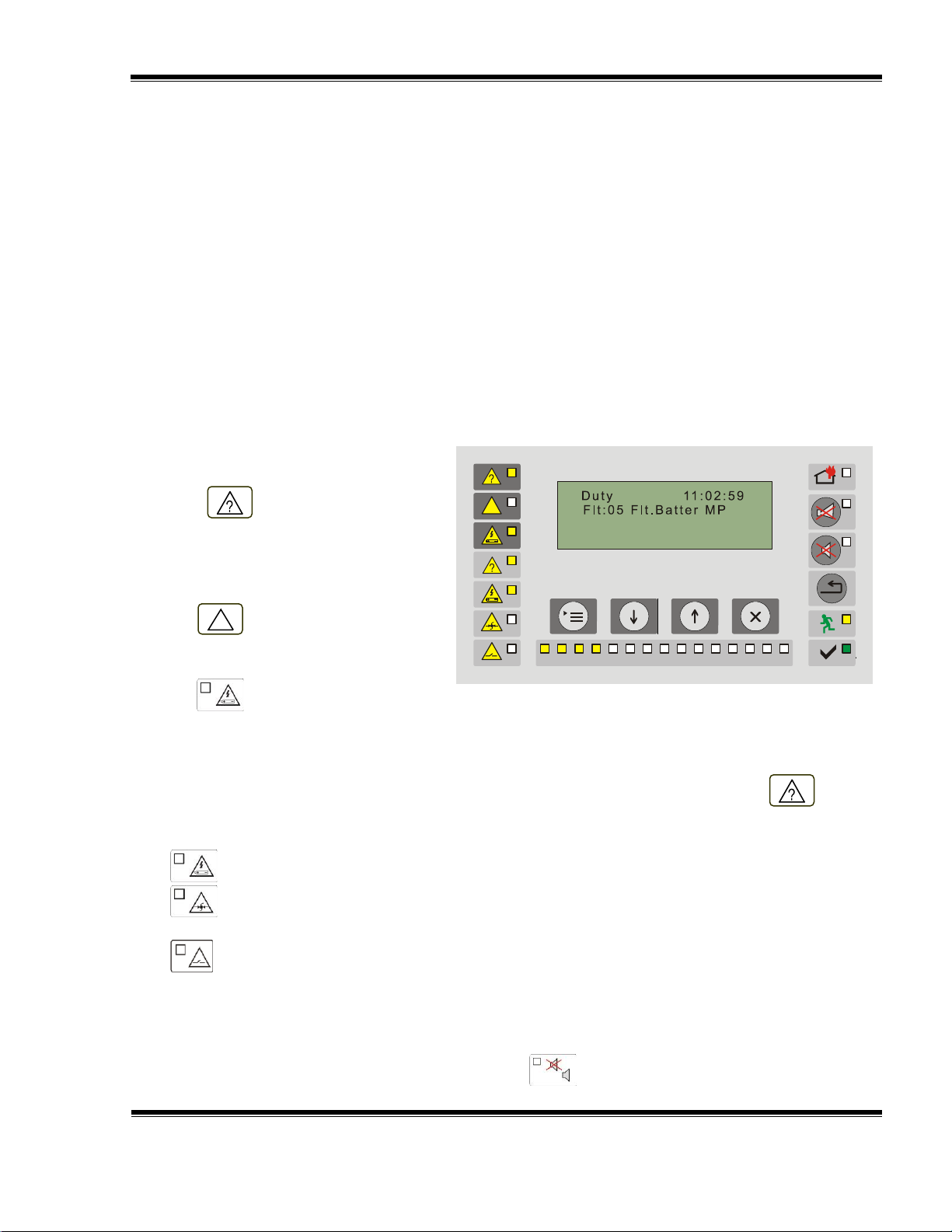
6.2. Indication
6.2.1. LED and sound indication
In Duty Mode the green LED indicator (Power supply) and the indicator upon
programmed inspection time of the outputs are activated.
6.2.2. Text message
6.2.3. Using the keypad
For all access levels the only active button in Duty Mode is (Menu). Press it and the
repeater enters System Functions status.

UniPOS Repeater FS5200R
Instruction Manual Page 10
Revision 3/01.17 of 48
In this condition the following indicators
illuminate:
indicator (Fire) in red light;
the individual indicator for Fire
condition of a remote fire control
panel illuminates in red light;
if the outputs of the repeater for
phase Fire condition are
suppressed by button
(Outputs), the LED indicator of
the button illuminates in
continuous red light;
1 2 3 4
5 6 7 8 9 10
11 12
13
14
15
For this condition the display is
divided into two text field:
the first field displays
information about the first
fire control panel and line
in fire condition;
the second field is used
to show information if
more than one fire control
panel (line) is in fire
condition.
If more than 2 lines are in fire
condition, use the buttons
(down) and (up) to view all lines
01 Fire s1/RP01/Ln02
Remote panel 01
03 Fire s2/RM01/Ln05
Remote panel 02
Serial
number of
the fire
Fire stage:
- Fire stage 1
- Fire stage 2
Remote panel
Line in Fire
(subject of reset)
Name remote
panel
First text field
Second text field
Line in Fire
Upon registration of more than 2 fire conditions,
the display visualizes continuous information about
7. Fire condition
7.1. Description
The repeater enters Fire condition after a fire condition has been activated in any of the
fire control panels or repeaters connected to it.
To exit this condition press button and the line in fire condition shown in the upper field of
the display is reset (section.7.3.3).
7.2. Indication
7.2.1. LED and sound indication
if the sound signaling is suppressed by button (Alarm), “Аларма”), the LED
indicator of the button illuminates in continuous red light.
7.2.2. Text messages

UniPOS Repeater FS5200R
Instruction Manual Page 11
Revision 3/01.17 of 48
in fire condition at the respective fire
control panels.
the first and the last fire condition (EN54-2).
Only the fire condition displayed in the first
text field could be reset.
7.3. Using the buttons
7.3.1. Button (Alarm)
Press it to:
turn the local sounder off if it is activated for Fire condition or Fault condition;
activate the local sounder if the fire control panel is in Fire condition or Fault condition
and the local sounder has been switched off by a preceding pressing of the same button.
The LED indicator of the button illuminates of the local sounder is switched off for Fire
condition or Fault condition.
Buttons’ operation does not effect an event, Fault condition and it is not cancelled by them.
A signal for a new fault condition/s will trigger the local sounder for Fault condition only.
7.3.2. Button (Outputs)
The button’s operation depends on the current Access level and the condition of the fire
control panel.
Press it to:
Suppress the outputs that have been activated for Fire condition.
Activate the suppressed outputs, if any.
The LED indicator of the button illuminates if there are suppressed outputs for Fire condition.
7.3.3. Button (Line Reset)
The button is used to force the line of the remote fire control panel to exit Fire condition.
The procedure to reset a line in which the remote fire control panel is in Fire condition
includes the following steps:
- Select a line – Using the buttons (Down) and (Up) in
the first text field of the display it is visualized the line which status is
going to be changed The line and the fire control panel shown in the
first text field is considered to the selected one;
- Control action – Pressing the button (Line Reset) has a
controlling action from the repeater to the remote fire control panel in
Fire condition and the line is reset (i.e. the remote fire control panel is
in Duty Mode for that line).
Note: If the remote fire control panel is FS4000 or FS5200E type,
pressing the button (Line Reset) results in forced exit of all lines of
the fire control panel from Fire condition not only of a single line.
The above-described steps (select a line/fire control panel and control action) are repeated
for every line in Fire condition that is being reset.
You can reset lines (fire control panels) in Fire condition from any repeater included in the
system.

UniPOS Repeater FS5200R
Instruction Manual Page 12
Revision 3/01.17 of 48
In the first text field:
01 (the first occurred fire condition);
1с (phase of fire condition);
RP03 (No. of the remote panel in fire condition);
Ln02 (No. of line in fire condition);
Building 1 (user’s text showing where the remote panel
is located (see section 10.4.5.2.4)).
In the second text field:
03 (the last occurred fire condition, in this case the third
one);
1с (fire condition Stage 1);
01 Fire s/RP03/Ln02
Building 1
03 Fire s1/RP05/Ln01
Warehouse
First text field
Second text field
Using the buttons (Down) and
(Up) in the first text field you can visualize the data for
the line that has to be reset. This line will be forced to
exit fire condition.
Reset the fire signal transmitted from line 1 of
remote panel 3, located in building 1.
02 Fire s1/RP03/Ln01
Building 1
03 Fire s1/RP05/Ln01
Warehose
First text field
Second text field
Example:
It is created a system of 5 fire control panels and two repeaters (Appendix 1)
Signals for Fire conditions in two remote fire control panels are received in the repeaters:
- Fire condition in lines 1 and 2 of the fire control panel in Building 1;
- Fire condition in line 1 of the fire control panel in Warehouse;
The following information is visualized on the display of the repeater.
RP5 (the fire condition is in remote panel No. 5)
Ln01 (No. of line in fire condition);
Warehouse (user’s text showing where the remote panel is located (see section 10.4.5.2.4)).
Based on the number of the first and the last fire condition it is evident that during the
time of the fire conditions shown on the display there is another fire condition but its visualizing is
suppressed at the moment. Use the buttons (Down) and (Up) to review the
suppressed messages for fire condition.
Pressing the button (Line Reset) in this screen results in:
- Line 1 from Building 1 exits Fire condition and enters Duty Mode;
- The other two lines in Fire condition are visualized. .

UniPOS Repeater FS5200R
Instruction Manual Page 13
Revision 3/01.17 of 48
Total number of lines in Fire condition – 2
First text field:
First occurred fire condition – line 2 in Building 1
Second text field:
Last occurred fire condition – line 1 in Warehouse.
Note: There are no suppressed messages for fire
conditions.
01 FIre s1/RP03/Ln02
Building 1
02 Fire s1/RP05/Ln01
Warehouse
First text field
Second text field
After a confirmation is received from the remote fire control panels (up to 10 seconds) that
their lines have been reset and are not in Fire condition, the repeaters enter Duty Mode. If during
Fire Condition the menus are manipulated, it is not possible the Fire condition to be reset.
Attention!
The remote fire control lines are reset only after a check is performed for false
activation. The control action of the repeaters will switch off the activated outputs of the
remote fire control panels for fire condition.
7.3.4. Button (Menu)
Press the button to enter Information and Control Mode.
7.3.5. Button (Exit)
Press it to return to the main screen.
8. Fault Condition
8.1. Description
The repeater enters Fault condition when a fault is registered in:
the repeater;
the remote fire control panels (repeaters) connected to it.
It is accessible at all Access levels.
8.1.1. The repeater enters Fault Condition when any of the events below have been
registered:
Battery low - backup batteries discharged due to interruption of mains supply;
Fault in a processor program;
Fault in a monitored output – short circuit or break;
Fault in the mains supply;
Fault in the backup batteries supply;
Short circuited ground wire;
Fault in external devices supply.
8.1.2. The repeater enters Fault Condition when any of the events below have been registered in
remote fire control panels, too:
UniPOS Repeater FS5200R
Instruction Manual Page 14
Revision 3/01.17 of 48
All other fault conditions in the
repeater are designated by indicator
pos. 1 (Fault) illuminating in
flashing yellow light. Depending on the
specific fault, the following indicators
are illuminated too:
upon System error - indicator
pos. 2 (System error) in
continuous yellow light;
pos. 3 (Fault in mains
supply) in continuous yellow
light;
1 2 3 4
5 6 7 8 9 10
11 12
13
14
15
Battery low - backup batteries discharged due to interruption of mains supply;
Fault in a processor program;
Fault in a monitored output – short circuit or break;
Fault in the mains supply;
Fault in the backup batteries supply;
Fault in a line – removed fire detector, short circuit or break;
Short circuited ground wire;
Fault in external devices supply
In any fault condition of the remote fire control panel with its specific functions.
In Fault condition text messages showing the type of the fault appear on the LCD display.
Additional information is provided by LEDs indicators.
8.2. Indication
8.2.1. LED and sound indication
Upon Low battery fault condition no LED indicator is illuminated. The local sounder produces
discontinuous signal (1 s sound, followed by 3 s break). The lighting of the LCD display is off.
For any fault condition in the remote fire control panels, indicator pos. 4 (Fault)
illuminates in flashing yellow light. Depending on the specific fault, the following indicators are
illuminated too:
pos. 5 (Fault in mains supply) in continuous yellow light.
light;
light;
yellow light.
If the sound indication is suppressed by button (Alarm), the LED indicator of button
illuminates in red light.
pos. 6 (Fault in a fire detecting line of a remote fire control panel) in continuous yellow
pos. 7 (Fault in a monitored output of a remote fire control panel) in continuous yellow
The individual indicator for a Fault condition in a remote fire control panel illuminates in

UniPOS Repeater FS5200R
Instruction Manual Page 15
Revision 3/01.17 of 48
Upon registration of a fault/s
condition the LCD display provides
information about:
The total number of fault
events;
Type of the fault event
Control panel in fault
condition
The information on fault
conditions is displayed only if the
repeater is not in fire condition.
Duty mode 11:02.59
Flt:05 Flt.Battery MP
Mode
Fault type
Real time clock
Total number of
faults
Panel in
Fault
Text message
meaning
FaultMainsRP
Fault in mains supply of remote panel No. ... (slave fire control panel
or repeater)
FaultLnRP
Fault in a line of remote panel No. ... (slave fire control panel or
repeater)
FaultMOutRP
Fault in a monitored output of remote panel No. ... (slave fire control
panel or repeater)
FaultRP
Fault in remote panel No. ... (slave fire control panel or repeater)
FaultEartRP
Fault in earthing of remote panel No. ... (slave fire control panel or
repeater)
FaultFsMP
Fault in a fuse on the main panel (repeater)
FaultMOut2ShortMP
Short circuit in monitored output 2 of the main panel (repeater)
FaultMOut2BreakMP
Break in monitored output 2 of the main panel (repeater)
FaultMOut1ShortMP
Short circuit in monitored output 1 of the main panel (repeater)
FaultMOut1BreakMP
Break in monitored output 1 of the main panel (repeater)
FaultErthMP
Fault in earthing of the main panel (repeater)
FaultBatMP
Fault in battery back up of the main panel (repeater)
FaultMSMP
Fault in mains supply of the main panel (repeater)
8.2.2. Text messages
The most frequently indicated fault conditions in the repeater are:
8.3. Using the buttons
For fault conditions 2 active buttons are being supported. Where the fire control panel
operates in combination of other conditions, their buttons are active too.
8.3.1. Button (Alarm)
Press it to:
switch the local sounder off if it was activated for Fire condition or Fault condition;
activate the local sounder if the fire control panel is in Fire condition or Fault condition
and the local sounder has been switched off by a preceding pressing of the same button.
The LED indicator of the button illuminates of the local sounder is switched off for Fire
condition or Fault condition.

UniPOS Repeater FS5200R
Instruction Manual Page 16
Revision 3/01.17 of 48
Enter Information and Control
Mode to review the fault events.
Upon pressing the button
(Menu) the following options are
available:
01 Review Faults
02 Review Disables
03 Review Statuses
04 System Function
1 2 3 4
5 6 7 8 9 10
11 12
13
14
15
Press the button
(Menu) again to enter submenu
Review Faults.
Information about the first fault
appears on the display. Use the
buttons (Down) and (Up)
to display the rest of the fault
conditions.
1 2 3 4
5 6 7 8 9 10
11 12
13
14
15
Press button (Exit) to exit
the review of the faults.
Upon exit the fire conditions the
LED and sound indication is switched
off.
1 2 3 4
5 6 7 8 9 10
11 12
13
14
15
A new fault condition will trigger the local sounder for Fault condition only.
8.3.2. Button (Menu)
Press the button to enter Information and Control Mode.
8.3.3. Buttons (Down) and (Up)
Press the buttons to see on the display the next/previous fault conditions.
8.3.5. Button (Exit)

UniPOS Repeater FS5200R
Instruction Manual Page 17
Revision 3/01.17 of 48
Upon pressing the button
(Menu) the following options are
available:
01 Review Faults
02 Review Disables
03 Review Statuses
04 System Function
Press the button (Down)
three times to move the cursor to
System Functions.
1 2 3 4
5 6 7 8 9 10
11 12
13
14
15
Press the button
(Menu) again to enter submenu:
01 Indication check
02 Clock
03 Disable outputs
04 Parameters reviews
Press the button (Down)
twice to move the cursor to Disable
Outputs.
1 2 3 4
5 6 7 8 9 10
11 12
13
14
15
9. Disabled Component
9.1. Description
The repeater enters Disabled component after a manual operation, disabling a specific
component – monitored output or relay for fire condition. A disabled monitored output is switched
off and is not monitored for fault condition.
That condition is controlled via the screens of System Functions.
Its control is accessible from all Access levels.
9.2. Indication
9.2.1. LED and sound indication
No LED and sound indication is supported for Disabled component condition.
9.2.2. Text messages
The text messages are displayed in System information condition.
9.3. Using the buttons

UniPOS Repeater FS5200R
Instruction Manual Page 18
Revision 3/01.17 of 48
Confirm the selection with
button (Menu) and use the
buttons (Down) and
(Up) to select the output to be
disabled.
Confirm the selection with
button (Menu).
1 2 3 4
5 6 7 8 9 10
11 12
13
14
15
After confirming the selection
with button (Menu), use the
buttons (Down) and
(Up) to choose the condition of the
selected output (Off/On).
Confirm the change with button
(Menu) or cancel the change
with button (Exit).
1 2 3 4
5 6 7 8 9 10
11 12
13
14
15
Upon confirming the change
with button (Menu) a
message appears that the change is
saved and for exit the menu.
1 2 3 4
5 6 7 8 9 10
11 12
13
14
15
Where an output is disabled it is not activated for Fire condition and data are not
processed for a Fault condition in the monitored outputs line.

UniPOS Repeater FS5200R
Instruction Manual Page 19
Revision 3/01.17 of 48
Enter the main menu
with button
(Menu);
Press once
(Down) and the cursor
moves to “02 Review
Disables;
Confirm the selection
with button
(Menu);
The entered disables are
displayed (e.g. Out1,
Out2, RelFr) or if there
are no disables – “No
disables” is shown;
To exit the menu use
button (Exit).
1 2 3 4
5 6 7 8 9 10
11 12
13
14
15
1 2 3 4
5 6 7 8 9 10
11 12
13
14
15
9.4. Review of the entered disables
Enter Information and Control Mode to review the entered disables. The menu is accessible for
all Access levels.
10. Information and Control Mode
Information and Control Mode provides the user with the possibilities to:
- display information about the repeater;
- enter control data;
- display information about the connected fire control panels (repeaters).
To enter Information and Control Mode, press button on the screen for Duty Mode,
Fire Condition, Fault Condition (with the exception of the screen for fatal error) and Disabled
component which suppresses their text messages.
.
The following buttons are active in Information and Control Mode:
- button (Menu);
- button (Down);

UniPOS Repeater FS5200R
Instruction Manual Page 20
Revision 3/01.17 of 48
- button (Up);
- button (Exit).
No specific LEDs or sound indication is provided for Information and Control Mode.
The screens visualized on the display are organized in a tree structure, containing
subordinate menus.

UniPOS Repeater FS5200R
Instruction Manual Page 21
Revision 3/01.17 of 48
Main menu
Preview faults Preview disables Preview Statuses System functions
01 StatRemPanel 01
02 StatRemPanel 02
03 StatRemPanel 03
...................................
...................................
15 StatRemPanel 15
16 Status “Out1”
17 Status “Out2”
Check
Indication
Clock
Outputs
disable
Preview
Parameters
SetUp Fire counters Archive
01 Date
02 Day
03 Time
04 Correction
01 Disable Output 1
02 Disable Output 2
03 Disb.Relay Fire
01 Delay output
02 Master/Slave
03 Ground check
04 Network address
05 Software version
01 Remote panel
03 Time delay
Output
02 Configuring 04 Default
parameters
05 Archive
clearing
06 New
password
01 Network address
02 Master/Slave
03 Language
04 Ground check
Remote panel 01
01 On/Off
02 Panel type
03 Network address
04 Text message
Remote panel 03
01 On/Off
02 Panel type
03 Network address
04 Text message
Remote panel 02
01 On/Off
02 Panel type
03 Network address
04 Text message
Remote panel 15
01 On/Off
02 Panel type
03 Network address
04 Text message
05 Test Outs.Fire

UniPOS Repeater FS5200R
Instruction Manual Page 22
Revision 3/01.17 of 48
The menu displays the status
of the remote fire control panels
(repeaters) and the monitored outputs
of the repeater.
1 2 3 4
5 6 7 8 9 10
11 12
13
14
15
Upon entering the menu a
screen appears for selecting the
remote fire control panel or monitored
output of the repeater which status is
to be reviewed.
Use buttons (Down),
(Down) and (Menu) to
select the object for visualization.
1 2 3 4
5 6 7 8 9 10
11 12
13
14
15
The displayed information has the
following structure:
- No. of the remote fire
control panel;
- Type of the connected
fire control panel;
- Status –Duty Mode or
Fault condition;
- Name of the remote
fire control panel.
To exit the menu use button
(Exit).
1 2 3 4
5 6 7 8 9 10
11 12
13
14
15
10.1. Submenu Review Faults
This submenu displays the registered fault conditions in the repeater and the remote fire
control panels (see section 8. Fault condition).
10.2. Submenu Review Disables
This menu provides visual information about the disables for activating the monitored outputs
and the fire relay (see section 9.4. Review of the entered disables).
10.3. Submenu Review Statuses

UniPOS Repeater FS5200R
Instruction Manual Page 23
Revision 3/01.17 of 48
The menu contains the
following subordinate menus and
functions:
- Check indication;
- Clock;
- Disable outputs;
- Review Parameters;
- Setup;
- Fire counter;
- Archive.
1 2 3 4
5 6 7 8 9 10
11 12
13
14
15
The screen to select the function
has the following appearance:
Press the button (Menu) to
activate the check.
ТAll LEDs indicators should
illuminate as the individual indicators of
the connected fire control panels
change their indication periodically from
yellow to red.
The sound signaling is continuous.
Use the button (Exit) to
deactivate the check.
1 2 3 4
5 6 7 8 9 10
11 12
13
14
15
1 2 3 4
5 6 7 8 9 10
11 12
13
14
15
10.4. Submenu System Functions
10.4.1. Function Check indication

UniPOS Repeater FS5200R
Instruction Manual Page 24
Revision 3/01.17 of 48
The menu is selected from
menu System Functions. Press twice
button (Down) and confirm with
button (Menu).
The menu contains the following
functions:
- calendar date;
- day of the week;
- the time
- calibration index
1 2 3 4
5 6 7 8 9 10
11 12
13
14
15
10.4.2.1. Function Date
Use this function to set or
adjust the current calendar date.
Upon activation of the function
the factory set date appears and the
cursor flashes on the first left digit of
the date. Admissible values are:
- for the date (two
characters, 0131)
- for a month (two
characters, 012)
- for a year (four
characters)
Use:
1 2 3 4
5 6 7 8 9 10
11 12
13
14
15
10.4.2.2. Function Day
Use this function to adjust the
current day of the week. The field
contains the current day.
Upon activation a screen appears
with the entered current day of the
week.
To change, save the data and to
exit the function, use:
buttons (Down) and
(Up) for selecting the day (Monday,
Tuesday, etc.);
1 2 3 4
5 6 7 8 9 10
11 12
13
14
15
10.4.2. Submenu Clock
button (Down) – to change the calendar date;
button (Up) – to move to the next character;
button (Menu) – to confirm the entered or set calendar date;
button (Exit).

UniPOS Repeater FS5200R
Instruction Manual Page 25
Revision 3/01.17 of 48
button (Menu) – to confirmed
the entered day;
button (Exit).
10.4.2.3. Function Time
Use this function to set or adjust
the current time.
Upon activation of the function
the factory set time appears and the
cursor flashes on the first left digit of
the hour. Admissible values are:
- for hour (two characters, 0023);
- for minutes (two characters, 0059);
- for seconds (two characters, 0059).
Use:
1 2 3 4
5 6 7 8 9 10
11 12
13
14
15
10.4.2.4. Function Calibration
Use this function to “accelerate/
delay” the clock. Each entered
positive unit (“+”) accelerates the
clock at the rate of 10,7s per month;
each negative unit delays the clock at
the rate of 5,35s per month.
The maximum rate is е +5,5min per
month or -2,75min per month
1 2 3 4
5 6 7 8 9 10
11 12
13
14
15
button (Down) – to change the value of the hour;
button (Up) – to move to the next character;
button (Menu) - to confirmed the entered or adjusted date;
button (Exit).

UniPOS Repeater FS5200R
Instruction Manual Page 26
Revision 3/01.17 of 48
The screen for activation of
the menu is displayed as follows:
The operations for disable
of outputs, monitored and/or relay
are described in details in section 9
Disabled Component”.
1 2 3 4
5 6 7 8 9 10
11 12
13
14
15
10.4.4.1. Function Delayed time
Output
This function provides information
about the programmed inspection
time. Possible values are from 0 to
255 seconds.
1 2 3 4
5 6 7 8 9 10
11 12
13
14
15
10.4.3. Submenu Disable Outputs
10.4.4. Submenu Review Parameters
The menu allows for reviewing the parameters entered in the fire control panel.
It contains information about:
- Entered delayed times of the outputs;
- The logical place of the repeater in relation to the connected fire control panels;
- Is the option Ground Check switched on;
- Network address of the repeater;
- The software version.
Use:
buttons (Down) and (Up) – to move the cursor in the menu;
button (Menu) – to select an item of the menu;
button (Exit).

UniPOS Repeater FS5200R
Instruction Manual Page 27
Revision 3/01.17 of 48
10.4.4.2. Function Master/Slave
This function provides
information about the logical level of
connection of the repeater.
Possible options are:
- Master;
- Slave.
1 2 3 4
5 6 7 8 9 10
11 12
13
14
15
10.4.4.3. Function Check Ground
The function has the two
possibilities:
- On;
- Off.
1 2 3 4
5 6 7 8 9 10
11 12
13
14
15
10.4.4.4. Function Network Address
The network address of the
repeater is visualized in this function.
Possible values from 0000 to 9999, as
the network address must be unique
within the connected repeaters and fire
control panels.
This parameter is setup from
menu SetUp and requires Access
Level 3 or 4.
1 2 3 4
5 6 7 8 9 10
11 12
13
14
15
10.4.4.5. Function Software Version
This function provides information
about the software of the repeater.
1 2 3 4
5 6 7 8 9 10
11 12
13
14
15

UniPOS Repeater FS5200R
Instruction Manual Page 28
Revision 3/01.17 of 48
Access to the Setup menu is
provided through submenu System
Functions of the main menu.
The operations in Menu Setup
require Access Level 3 or 4. Enter a
password (four-digit number) to have
an access to the menu. The factory
set password is “0000”.
Use:
button (Down) – to
change the character;
button (Up) – to move
to the next character;
button (Menu) – to
confirm the entered
password;
button (Exit).
The menu has the following
subordinate menus:
01 Repeater
02 Configuration
03 Time Delay
04 Factory settings
05 Clear archive
06 New password
1 2 3 4
5 6 7 8 9 10
11 12
13
14
15
1 2 3 4
5 6 7 8 9 10
11 12
13
14
15
1 2 3 4
5 6 7 8 9 10
11 12
13
14
15
10.4.5. Submenu Setup
It is used for setting the configuration parameters of the repeater.
10.4.5.1. Menu Repeater
Use this menu to setup:
Network address of the repeater – unique four-digit number for the connected fire control
panels (it is setup only when the repeater operates as SLAVE),;
Logical place – the status of the repeater in relation to the connected fire control panels
(master/slave);
Language – Menu language of the repeater (Bulgarian, English or Russian);
Check ground – switched on or off;
UniPOS Repeater FS5200R
Instruction Manual Page 29
Revision 3/01.17 of 48
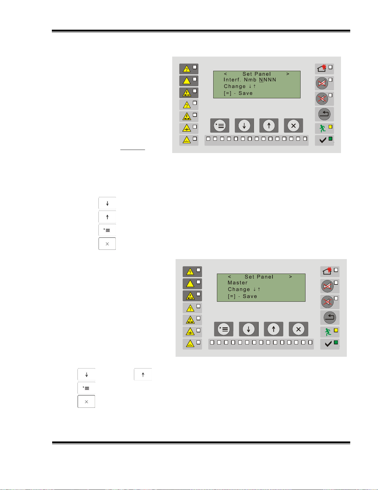
10.4.5.1.1. Screen network
Address
The setting Network Address
is valid only in the case when the
repeater is a SLAVE one, i.e. when
a network of more than one
repeater is created. In this case the
repeater is equal to all connected
fire control panels and its address
is described in the menu
Configuration Remote Control
Panels” (see section10.4.5.2).
1 2 3 4
5 6 7 8 9 10
11 12
13
14
15
10.4.5.1.2. Screen Master/Slave
This parameter points the logical
place of the repeater in the system of
connected fire control panels.
The parameter is not related to the
physical location of the repeater
but with the logical structure of the
system.
In one system of connected
fire control panels there is only
one repeater defined as Master
and up to 15 fire control panels
(repeaters) defined as Slave.
1 2 3 4
5 6 7 8 9 10
11 12
13
14
15
Check of fire outputs.
The network address is unique for each connected object within one system.
It identifies the repeater.
A screen for entry of the data appears in setting (entry) of a network address.
The permissible values of the network address are from 0000 to 9999.
Use:
button (Down) – to change the character;
button (Up) – to move to the next character;
button (Menu) – for confirmation;
button (Exit).
Use the buttons:
(Down) and (Up) – for alternating change Master/Slave;
(Menu) – to confirm;
(Exit) – to exit.

UniPOS Repeater FS5200R
Instruction Manual Page 30
Revision 3/01.17 of 48
10.4.5.1.3. Screen Language
The repeater supports menus in
three languages:
- Bulgarian;
- English;
- Russian.
Use the buttons (Down)
and (Up) for alternating
change of the language.
1 2 3 4
5 6 7 8 9 10
11 12
13
14
15
10.4.5.1.4. Screen Check Ground
The screen provides the
information if check ground is being
performed or not.
The possible options of the
parameter are – Check ground
switched ON or OFF.
For the alternating change of this
parameter use the buttons
(Down) and (Up).
1 2 3 4
5 6 7 8 9 10
11 12
13
14
15
10.4.5.1.5. Function Test Fire
Outputs
This function tests the fire
outputs. When the parameter is
changed from OFF to ON the fire
outputs of the repeater are activated.
For the alternating change of
this parameter use the buttons
(Down) and (Up), to exit the
function use the button (Exit).
1 2 3 4
5 6 7 8 9 10
11 12
13
14
15
Attention! Regardless of the last entered position of the parameter (ON/OFF) it is automatically
restored to OFF position upon exit of the function.
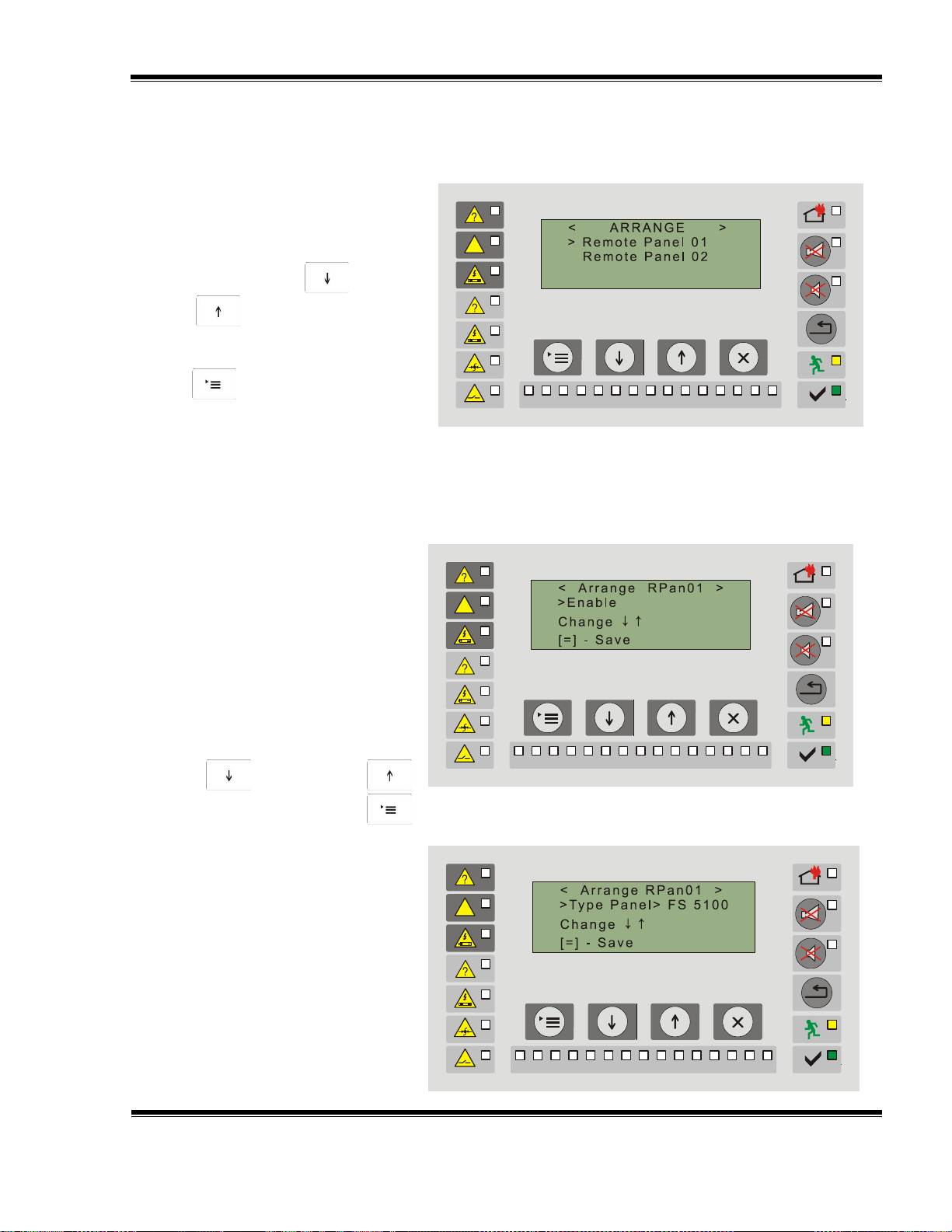
10.4.5.2. Menu Configuration
Use this submenu for setting the parameters of the connected to the repeater fire control
panels and repeaters:
Is the fire control panel going to be ON or OFF – in the cases when a fire control panel
has to be switched off for repair, test, etc.
UniPOS Repeater FS5200R
Instruction Manual Page 31
Revision 3/01.17 of 48
Enter the menu and a screen
for selecting the No. of the remote
panel (fire control panel) to be
configured appears.
Use the buttons (Down)
and (Up) to select the
remote panel.
Confirm the selection with
button (Menu).
1 2 3 4
5 6 7 8 9 10
11 12
13
14
15
This option is suitable in the
cases when preventive
maintenance, tests, repair or other
operations are performed to any of
the connected fire control panels.
The fire control panel that is
switched off is not monitored by the
repeater. The possible options for
this parameter are: panel ON or
OFF.
To select the option use the
buttons (Down) and
(Up), to confirm – the button
(Menu).
10.4.5.2.2. Screen Panel Type
This screen is used for setting
the type of the connected remote
fire control panel (repeater). The
possible types are:
- FS 5100;
- FS 5200;
- FS 5200E
- FS 4000;
- FS 5200R.
To select the type use the
1 2 3 4
5 6 7 8 9 10
11 12
13
14
15
1 2 3 4
5 6 7 8 9 10
11 12
13
14
15
Type of the panel – determines the type of the connected fire control panel (repeater).
Network address – the unique for-digit network address within the system.
Text message – text, convenient for the user in order to distinguish the remote fire control
panels.
The configuration procedure described for one remote object should be repeated for all
remote fire control panels.
10.4.5.2.1. Screen On/Off
This screen provides the option for switching on or off a remote fire control panel from the
entire system.

UniPOS Repeater FS5200R
Instruction Manual Page 32
Revision 3/01.17 of 48
buttons (Down) and
(Up), to confirm – the button
(Menu).
10.4.5.2.3. Screen Network
Address
Use this screen to enter the
network address of the remote fire
control panel.
The entered address should be
unique for the created system of
connected fire control panels, i.e.
only that fire control panel
(repeater) must be identified by it.
The permissible values of the
network address are four-digit
numbers from 0000 to 9999.
1 2 3 4
5 6 7 8 9 10
11 12
13
14
15
10.4.5.2.4. Screen Text Message
Use this screen to enter the
“user’s name” of each of the
connected remote fire control
panels.
This option provides better
possibilities for identification of
each connected remote fire control
panel, as the user could choose its
name for better identification.
1 2 3 4
5 6 7 8 9 10
11 12
13
14
15
To enter the address, use:
button (Down) – to change a character;
button (Up) – to move to the next character;
button (Menu) – to conform;
button (Exit).
Note: When the connected remote fire control panel is FS4000 type, the network address is fixed
as it coincides with the serial number of the fire control panel.
After the name is entered, all messages referring that remote fire control panel will be
visualized and displayed with the name assigned by the user.
The length of the text field is maximum 20 characters.
The factory setup displays the message “REMOTE PANEL NN” (REMOTE PANEL NN), where
NN is the number of the remote fire control panel (01-15).
When the screen is displayed the cursor begins to flash on the first character.

UniPOS Repeater FS5200R
Instruction Manual Page 33
Revision 3/01.17 of 48
This screen provides the option
for setting the time delay for
switching the outputs of the
repeater.
The entered time is in seconds
within the range 0 to 255 seconds.
This parameter is factory setup
to 120 seconds.
To setup the time delay, use the
buttons:
1 2 3 4
5 6 7 8 9 10
11 12
13
14
15
The factory settings are:
Password: 0000
Network address: 1234
Master/Slave: MASTER
Language: BULGARIAN
Check ground: ON
Time delay: 120 seconds
Disabled outputs: NO
1 2 3 4
5 6 7 8 9 10
11 12
13
14
15
To enter the text, use:
button (Down) – to change the character (all letters from the Bulgarian and Latin
alphabets, space);
button (Up) – to move to the next character;
button (Menu) – to conform;
button (Exit).
10.4.5.3. Function Time Delay
(Down) – press it once to decrease the time by 1 second;
(Up) - - press it once to increase the time by 1 second;
(Menu) – to confirm the change;
(Exit).
10.4.5.4. Function Factory Settings
The screen returns the parameters of the repeater to their default settings.
Use the buttons (Menu – to confirm the change and/or (Exit).

UniPOS Repeater FS5200R
Instruction Manual Page 34
Revision 3/01.17 of 48
Press the button (Menu).
“Меню”) to activate the function and
to delete the archive. The information
for the events, saved in the energy
independent memory is deleted.
The fire counter is not cleared.
It is reset in a special mode.
1 2 3 4
5 6 7 8 9 10
11 12
13
14
15
Upon activation a screen
appears as the cursor is positioned
on the first digit of the previous (or
factory setup) password.
1 2 3 4
5 6 7 8 9 10
11 12
13
14
15
This function displays
information about the total number of
fire conditions, registered after the
initial switching of the repeater.
The number of the occurred
fire conditions is saved in an energy
independent archive. It could not be
adjusted or deleted.
1 2 3 4
5 6 7 8 9 10
11 12
13
14
15
10.4.5.5. Function Clear Archive
When this function is selected a screen appears to confirm the deletion or to exit the
screen without deletion.
10.4.5.6. Function New Password
The function allows the user to change the password for access (for levels 3 and 4).
10.4.6. Function Fire Counter

UniPOS Repeater FS5200R
Instruction Manual Page 35
Revision 3/01.17 of 48
This function allows
information to be displayed for the
events, saved in the energy
independent memory. The structure
of the shown information is as
follows:
- No. of the record;
- total number of the
records;
- text of the event in
the archive;
- time of the record;
- date of the record.
The permissible values for the
data are:
No. of the record – (from 0 to
100);
total number of the records –
(from 0 to 100);
text – event type. In which
connected fire control panel
the event is;
time – time of the event;
data – date when the event
occurred.
The maximum number of registered
events is 100 as if this number is
surpassed the newly-occurred events
replace the oldest ones (i.e. “first
comes - first goes” scheme is used).
1 2 3 4
5 6 7 8 9 10
11 12
13
14
15
Archive NN Tot.XXX
Out. Fault.Ground RP ZZ
hh:mm dd-mm-yyyy
Number of
record in the
archive
Total number of
records in the
archive
Location of the event:
RP – Remote Panel №
MP – Main Panel
Time of record in
archive
Date of record in
archive
Description of
the event
10.4.7. Function Archive
11. Labour protection requirements
The installation and maintenance staff shall be well grounded in equipment’s mechanism
and operation, as well as in common technical safety regulations.
Connection to unearthed or to indirectly earthing mains supply is prohibited.
Troubleshoots are to be cleared after disconnecting the feeding cable from the mains
supply.
The repeater is designed for installing in premises with a normal fire hazard, as per the Fire
Precaution Technical Regulations in Building Construction.
.

UniPOS Repeater FS5200R
Instruction Manual Page 36
Revision 3/01.17 of 48
12. Installation
When installing the peripheral devices to the Repeater avoid arranging wires in closed
loops; it will reduce the resistance of the repeater to electromagnetic interferences.
For the installation operations it is required Access level 2 or higher.
12.1. To mount the repeater
Unpack the repeater.
Check the content of the delivery.
Install the fixing pins at the specified places.
Open the front cover by turning the key to 90 degrees.
Install the repeater to dowels through the three holes on its back wall. It is recommended
not to install the repeater near sources of heat (radiators, air conditioners, etc.)
All inputs and outputs of the repeater are on a terminal row as on the monitored outputs
“Out1” and “Out2” resistance 5.6 k is installed.
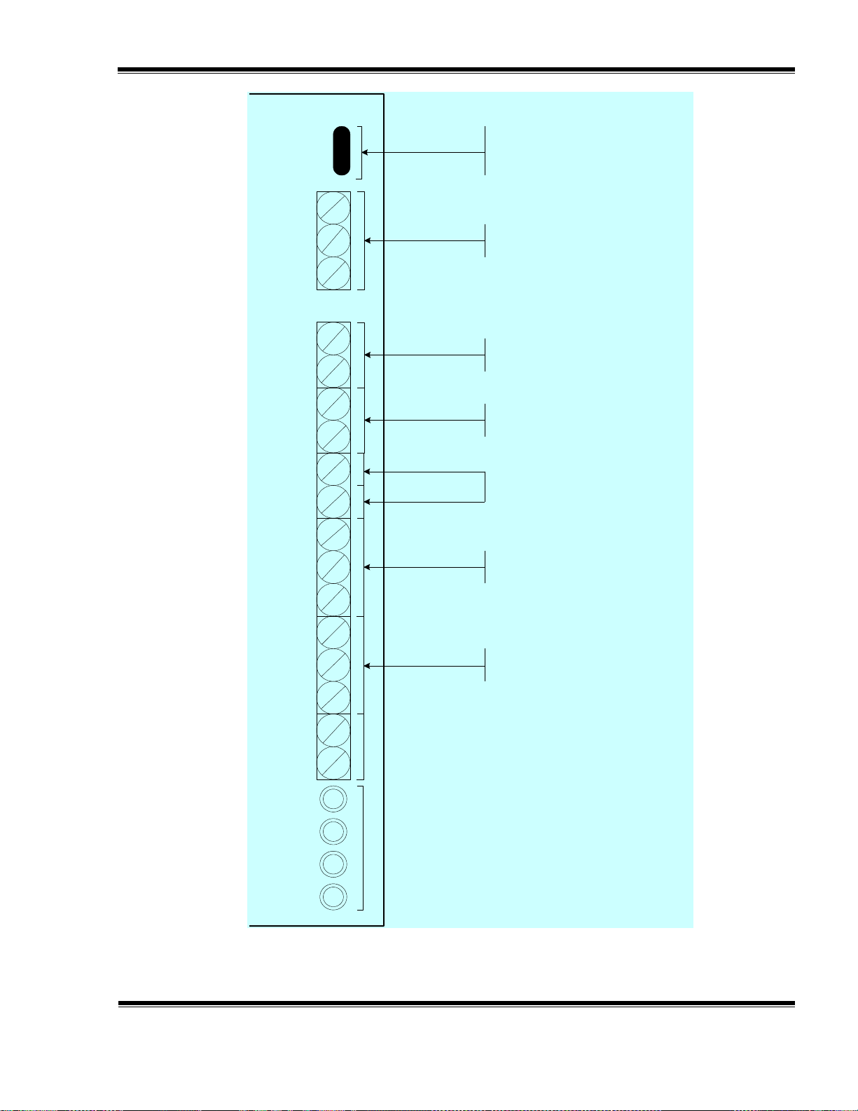
12.2. Inputs and outputs of the repeater
12.2.1 Description
All connections are made by means of terminals installed on the PC board. Remember
that the sum of the consumption for external devices voltage supply (at terminal “+28V”) and the
monitored output consumption should not exceed 1.2А in the most severe mode.
“GND” – Terminal for GND potential supply to peripheral devices
“-Out1+”, “-Out2+” – Outputs with active level and the line status monitoring.
The output switches on the sound-light signaling in case of Fire condition.
“Rele Fire” – Output, relay, potential free, the line status is not monitored. The
output controls the devices in case of Fire condition of remote fire control panels.
“REL Fault” – Output, relay, potential free, the line status is not monitored. The
output controls the devices in case of Fault condition, both on the repeater and
the remote fire control panels
“+28V” – Terminal for 28V voltage supply to peripheral devices.
“RS 485” – Terminals for connecting RS 485 interface two-wire line. The
connection to the peripheral fire control panels or repeaters is executed via this
interface. A jumper is provided which could shunt the line with resistor 120. It is
necessary if the repeater is a final point in the interface line. The interface
requires both ends of the line to be terminated with resistors 120.
A wide range of output devices could be connected to the repeater:
- built-in sounders
- external sounders
- control devices for fire detecting automation
- telephone dialer
- steel-plated sounders
UniPOS Repeater FS5200R
Instruction Manual Page 37
Revision 3/01.17 of 48
Jump
Jumper
RS485
B A
Out1 Out2 +28V
Interface RS485
Output with active level and the
line status monitoring Out1
Output with active level and the
line status monitoring Out2
NC NO C
Rel Fire
NC NO C
REL Fault
GND GND
+ 28 - RS485-w
Aw Bw
Terminal for 28V voltage
supply to peripheral devices
Output, relay, potential free, the
line status is not monitored
The output controls the devices
in case of Fault condition
12.2.2. Fire Relay Rel Fire
Relay Rel Fire is with potential free contacts, on the terminal row
– Normal open “NO”;

UniPOS Repeater FS5200R
Instruction Manual Page 38
Revision 3/01.17 of 48
- Out x +
5,6 k
– Normal Closed ”NC”;
– common point “С”.
In Duty Mode there is a circuit between “C” and “NС” terminals of the relay.
In Fire condition “NO” is closed a circuit is executed between “C” and “NO” terminals of the
relay.
The output is not monitored for short circuit and break.
The relay contacts don’t commutate 220V!
12.2.3. Relay Fault REL Fault
Relay REL Fault is with potential free contacts, on the terminal row
– Normal open “NO”;
– Normal Closed ”NC”;
– common point “С”.
The output is activated in Fault condition of the repeater.
In Duty Mode there is a circuit between “C” and “NO” terminals of the relay.
In Fault condition “NC” is closed a circuit is executed between “C” and “NC” terminals of the
relay, i.e. output device commutated through the contacts of REL Fault will signal the occurrence
of a fault condition.
The output is not monitored for break and short circuit.
The relay contacts don’t commutate 220V!
12.2.4. Monitored outputs “Out1” and “Out2”
The outputs are connected to the two-wire line for connection with sound and light signaling
devices.
The line is balanced as it is monitored for break and short circuit.
Resistor 5.6 к / 0.25W has to be installed to the signaling device terminals so that the
status could be monitored.
Voltage (24±3) V with load carrying capacity 1А is supplied upon activation of the outputs.
The outputs are activated for Fire condition in the remote fire control panel.
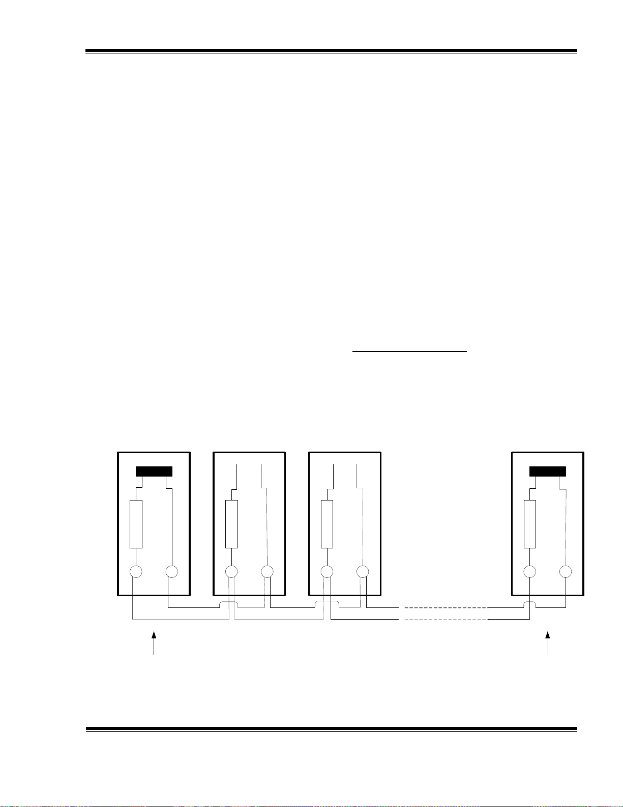
12.2.5. Interface RS485
12.2.5.1. Description
RS485 interface function is to transmit data and receive commands from FS4000,
FS5100, FS5200, FS5200Е remote fire control panels or FS5200R repeater.
FS5200R repeater receives data from fire control panels connected to it as it indicates
the occurred events by means of sound, light and text messages.
UniPOS Repeater FS5200R
Instruction Manual Page 39
Revision 3/01.17 of 48
120
120
120
120
A A A A BB B
B
J
J J J
Remote Panel No. Remote Panel No. Remote Panel No. Remote panel No.
First device in the line
(last for the network)
Last device in the line
(last for the network)
Each one connected device can be:
- Remote control panel FS5200R
- Control Panel FS4000
- Control Panel FS5100
- Control Panel FS5200
- Control Panel FS5200E
Based on the received data, if necessary, the fire control panels in Fire condition could be
reset by manual operation.
RS485 interface could be utilized also for communication to other intelligent devices and
computers.
The data exchange rate is 9600 [Bits/s].
12.2.5.2. Connection
The connection between the devices along RS485 is executed by parallel connection along
the two-wire line as it should be observed potential “A” and “B” not to be crossed. The maximal
distance between the final point devices is 1200 meters.
The recommended connecting wire cross section should not be less than:
Up to 500 m - connecting wire 2 х 0.5 мм2
Up to 1000 m - connecting wire 2 х 1.0 мм2
In the case of long distances or environment with electromagnetic radiation it is
recommended the wire to be double-core or shielded. If the wire is shielded, the shield should be
connected only in one end to “earth” terminal on the respective fire control panel or repeater.
Regardless the line length a jumper should be installed to the first and the last device to
terminate the line by 120 ohms. The jumper should be removed from all other devices.
ATTENTION! The setting MASTER/SLAVE (see section 10.4.5.1.2.) of the repeater and
the fire control panels connected to it does not depend on the physical location of the devices in
the network. The repeater could be physically connected anywhere in the line. If it is the first or
the last device (in RS485 there is only one two-wire line connected), it should be terminated with
the jumper. The same rule applies for the fire control panels too.
Connection to FS5100 and FS5200 fire control panels

UniPOS Repeater FS5200R
Instruction Manual Page 40
Revision 3/01.17 of 48
L – power supply wire “Phase”;
N – power supply wire “Zero”;
“Earth” – earthing wire.
L N
Fuse 4A
Interface PC board should be installed to the configuration of the fire control panels so that
FS1200 and FS5200 could operate with a repeater.
For FS5200 fire control panel the Interface PC board is fixed by means of the screws from
the set to the Base Unit and the ribbon cable is put in the coupling of the Base PC Board (see
the Instruction Manual of FS5200 fire control panel).
For FS5100 fire control panel the Interface PC board is installed directly on the Base PC
Board and is fixed by means of a screw (see the Instruction Manual of FS5100 fire control
panel).
Connection to FS5200Е fire control panel
The interface module is built-in on the base PC Board with these fire control panels and it is only
necessary the interface wires to be connected to the terminals for “A” and “B” potential,
respectively.
Connection to FS4000 fire control panel
In order to operate in a network FS4000 fire control panel has to be completed with an
extended PC Board where RS485 is located.
In the fire control panel it is fixed:
- network address – corresponds to the fire control panel serial;
- data exchange rate– 9600 Bits/s.
Checking the line resistance
With switched off power supply of all connected objects, the line resistance is measured
by means of an electronic measuring instrument (Multizet):
- If the measured resistance is in the range 45 60 - the line is within the
referent values;
- If the measured resistance is < 45 - there are more than two installed
terminating resistors in the line;
- If the measured resistance is > 60 - both ends of the line are not
terminated by resistance of 120 .
12.3. Power supply connection
Remove fuse Fs1 (4A) from the terminal with mains fuse.
Connect the power supply cable to the terminal with network fuse observing the following
layout:
The cable should be with double-insulation and cross section not less than 0.5mm2 for the
power supply wires and 1,5mm2 for the earthing wire.
Connect the other end of the power supply cable to the mains using a junction box.
The mains power supply of the fire control panel should be to a separate current circle.

UniPOS Repeater FS5200R
Instruction Manual Page 41
Revision 3/01.17 of 48
The display shows the
logo of the company-producer,
kind and type of the unit and
the software version.
UniPOS
Repeater
FS5200R V xx.xx
13. Repeater start up
13.1. Make sure that the connection to mains supply is properly made (see section 12.3).
13.2. Make sure that repeater and the fire control panel are properly connected in a common
network (see section 12.2.5.2.).
13.3. Place fuse Fs1 (4A) in the terminal with the mains fuse.
13.4. Connect the feeding cables to the backup.
Connect the red wire to the positive pole, and the blue wire – to the negative pole. The
overall voltage of both batteries shall exceed 17.6V, otherwise the fire control panel will not
recognize them.
Attention! The repeater operates with two backup batteries 12V in a series connection.
13.5. In Menu Setup-Repeater-Test Out.Fire (see section 10.4.5.1.5.)
Check the fire outputs.
13.6. In Menu Setup, program the main repeater (see section 10.4.5.1.)
The data are: default for changing
Password: 0000 see section 10.4.5.6.
Network address: 1234 (for slave repeater) see section 10.4.5.1.2.
Master/Slave: MASTER see section 10.4.5.1.1.
Language: BULGARIAN see section 10.4.5.1.3.
Check ground: ON see section 10.4.5.1.4.
Delayed time: 120 seconds see section 10.4.5.3.
Disabled outputs: NO see section 9.
Communication rate: 9600 Bits/s (fixed)
Setup the data for all connected objects ( see section 10.4.5.2.)
- On or off ( see section 10.4.5.2.1.);
- Network address ( see section 10.4.5.2.3.);
- Type of the device ( see section 10.4.5.2.2.);
- Text messages for the objects ( see section 10.4.5.2.4.);
13.7. Enter the required data for communication with the repeater in each remote control
panel:
- Network address – unique for the created system and coinciding
with the information entered in the repeater ( see section
10.4.5.2.3.);
- Communication rate - the data exchange rate of the repeater is
9600 [Bits/s], therefore this parameter should have the same value
in each remote fire control panel.
The settings in the main repeater and the remote devices should be accurate for the
communication to be realized.

UniPOS Repeater FS5200R
Instruction Manual Page 42
Revision 3/01.17 of 48
If the communication with a certain object fails due to any reason the repeater will display an
error message and the name of the devices with which there is no connection.
14. Conditions of operation, storage and transportation
14.1. Operation and storage
The repeater shall operate and be kept in closed premises, under the following conditions:
14.1.1. Temperature
- storage – from +5оС to +35оС
- transport – from –10оС to +50оС
- operational – from –5оС to +40оС
14.1.2. Relative humidity
- storage – to 80%
- operational – to 93%
14.2. Transportation
The repeater shall be transported
– by closed vehicles
– in factory packing
– in the above stated environmental conditions
– at sinusoidal vibrations with acceleration amplitude not more than 4,9m/s2
in frequency range 10 to 150Hz.
15. Warranty
The producer guarantees compliance of the device with BDS EN 54-2: 1997.
The warrant period is 24 months from the date of the purchase, providing that
the conditions of storage and transportation have been observed;
the startup has been done by authorized personnel by the producer.
the requirements for operation stated herein have been observed.
UniPOS wishes you a successful work!

UniPOS Repeater FS5200R
Instruction Manual Page 43
Revision 3/01.17 of 48
Building 1
FS5200
(slave)
Building 2
FS5100
(slave)
Building 3
FS5100
(slave)
Warehouse
FS5200E
(slave)
Administration
FS4000
(slave)
Security
FS5200R
(master)
Transport gate
FS5200R
(slave)
16. Appendix 1
Network of two repeaters (master and slave) and five slave fire control panels–Option 1
1. Setup of the master repeater
In the created network, the repeater that is being set up is the first one (end one) thus the
jumper for terminating with resistor 120 is on.
Menu – System Functions – Setup – Repeater (see section 10.4.5.1.)
Network address: not to be entered;
Master/Slave: MASTER;
Language: BULGARIAN
Check ground: ON
Menu – System Functions – Setup – Configuration (see section 10.4.5.2.)
Remote panel 01: ON/OFF: ON;
Type of panel: FS5200;
Network address: 1111 (random four-digit number);
Text message: BUILDING 1.

UniPOS Repeater FS5200R
Instruction Manual Page 44
Revision 3/01.17 of 48
Remote panel 02: ON/OFF: ON;
Type of panel: FS4000;
Network address: ХХХХ (the fire control panel serial number);
Text message: ADMINISTRATION
Remote panel 03: ON/OFF: ON;
Type of panel: FS5100;
Network address: 1010 (random four-digit number);
Text message: BUILDING 2.
Remote panel 04: ON/OFF: ON;
Type of panel: FS5100;
Network address: 1020 (random four-digit number);
Text message: BUILDING 3.
Remote panel 05: ON/OFF: ON;
Type of panel: FS5200Е;
Network address: 2222 (random four-digit number);
Text message: WAREHOUSE.
Remote panel 06: ON/OFF: ON;
Type of panel: FS5200R;
Network address: 1234 (random four-digit number);
Text message: TRANSPORT GATE.
2. Setup of the slave fire control panels and the slave repeater
2.1. Fire control panel in Building 1
Menu – System Functions – Setup – Fire Control Panel
Network number: 1111 (the same as the network number entered in RP1);
Interface rate: 9600.
The object is not the first one or the last one. The terminating resistor 120 is not on.
2.2. Fire control panel in Administration
Fire control panel of FS4000 type is not setup.
It is fixed in it:
Network number: ХХХХ (serial No. of the fire control panel, entered in RP 2);
Interface rate: 9600.
The object is not the first one or the last one. The terminating resistor 120 is not on.
2.3. Fire control panel in Building 2
Menu – System Functions – Setup – Fire Control Panel Parameters
Network number: 1010 (the same as the network number entered in RP3);
Interface rate: 9600.
The object is not the first one or the last one. The terminating resistor 120 is not on.
2.4. Fire control panel in Building 3
Menu – System Functions – Setup – Fire Control Panel

UniPOS Repeater FS5200R
Instruction Manual Page 45
Revision 3/01.17 of 48
Network number: 1020 (the same as the network number entered in RP4)
Interface rate: 9600.
The object is not the first one or the last one. The terminating resistor 120 is not on.
2.5. Fire control panel in Warehouse
Menu – System Functions – Setup – Fire Control Panel
Network number: 2222 (the same as the network number entered in RP5)
Interface rate: 9600.
The object is not the first one or the last one. The terminating resistor 120 is not on.
2.6. Repeater at the Transport Gate
In the created network, the repeater that is being set up is the last one (end one) thus the
jumper for terminating with resistor 120 is on.
Menu – System Functions – Setup – Repeater (see section 10.4.5.1.)
Network address: 1234 (the same as the network number entered in RP6)
Master/Slave: SLAVE;
Language: BULGARIAN
Check ground: ON
Interface rate: fixed

UniPOS Repeater FS5200R
Instruction Manual Page 46
Revision 3/01.17 of 48
Building 1
FS5200
(slave)
Building 2
FS5100
(slave)
Building 3
FS5100
(slave)
Warehouse
FS5200E
(slave)
Administration
FS4000
(slave)
Security
FS5200R
(master)
Transport gate
FS5200R
(slave)
Appendix 2
Network of two repeaters (master and slave) and five slave fire control panels–Option 2
1. Setup of the master repeater
The object is not the first one or the last one. The jumper for terminating the line is not on.
Menu – System Functions – Setup – Repeater (see section 10.4.5.1.)
Network address: not to be entered;
Master/Slave: MASTER;
Language: BULGARIAN
Check ground: ON
Menu – System Functions – Setup – Configuration (see section 10.4.5.2.)
Remote panel 01: ON/OFF: ON;
Type of panel: FS5200;
Network address: 1111 (random four-digit number);
Text message: BUILDING 1.

UniPOS Repeater FS5200R
Instruction Manual Page 47
Revision 3/01.17 of 48
Remote panel 02: ON/OFF: ON;
Type of panel: FS4000;
Network address: ХХХХ (serial No. of the fire control panel);
Text message: ADMINISTRATION.
Remote panel 03: ON/OFF: ON;
Type of panel: FS5100;
Network address: 1010 (random four-digit number);
Text message: BUILDING 2.
Remote panel 04: ON/OFF: ON;
Type of panel: FS5100;
Network address: 1020 (random four-digit number);
Text message: BUILDING 3.
Remote panel 05: ON/OFF: ON;
Type of panel: FS5200Е;
Network address: 2222 (random four-digit number);
Text message: WAREHOUSE.
Remote panel 06: ON/OFF: ON;
Type of panel: FS5200R;
Network address: 1234 (random four-digit number);
Text message: TRANSPORT GATE.
2. Setup of the slave fire control panels and the slave repeater
2.1. Fire control panel in Building 1
Menu – System Functions – Setup – Fire Control Panel
Network number: 1111 (the same as the network number entered in RP1);
Interface rate: 9600.
The object is not the first one or the last one. The terminating resistor 120 is not on.
2.2. Fire control panel in Administration
Fire control panel of FS4000 type is not setup.
It is fixed in it:
Network number: ХХХХ (serial No. of the fire control panel, entered in RP 2);
Interface rate: 9600.
The object is not the first one or the last one. The terminating resistor 120 is not on.
2.3. Fire control panel in Building 2
Menu – System Functions – Setup – Fire Control Panel Parameters
Network number: 1010 (the same as the network number entered in RP3);
Interface rate: 9600.
The object is not the first one or the last one. The terminating resistor 120 is not on.
2.4. Fire control panel in Building 3
Menu – System Functions – Setup – Fire Control Panel

UniPOS Repeater FS5200R
Instruction Manual Page 48
Revision 3/01.17 of 48
Network number: 1020 (the same as the network number entered in RP4)
Interface rate: 9600.
In the created network, the fire control panel that is being set up is the first (end one), thus it
is terminated with resistor 120 .
2.5. Fire control panel in Warehouse
Menu – System Functions – Setup – Fire Control Panel
Network number: 2222 (the same as the network number entered in RP5)
Interface rate: 9600.
In the created network, the fire control panel that is being set up is the last (end one), thus it
is terminated with resistor 120 .
2.6. Repeater at the Transport Gate
The object is not the first one or the last one. The terminating resistor 120 is not on.
Menu – System Functions – Setup – Repeater (see section 10.4.5.1.)
Network address: 1234 (the same as the network number entered in RP6)
Master/Slave: SLAVE;
Language: BULGARIAN
Check ground: ON
Interface rate: fixed
 Loading...