

Page 1
SECOND
EDITION
XF511B100MF XF511H112MG
XF511E101MF XF511H115MF
XF511E118MF XF512E100HB
XF511E152MF XF512E100MP
XF511H100MF XF513E100HJ
CATALOG NO. 142M
STYLES
XF511H100MG XF513E100HR
XF511H100MAW XF513E101HR
XF511H112MF XF513E112HR
Maximum performance XF500
Series flatbed machines
Page 2

FORWARD
This technical manual has been prepared to guide you in the maintenance of your new UNION
SPECIAL MACHINE. Careful attention to the instructions for operating and adjusting these
machines will enable you to maintain the superior performance and reliability designed and
built into every UNION SPECIAL machine.
The Adjusting Instruction portion of this manual explains in detail the proper setting for each
of the components related to forming the stitch and completing the functions of the machine.
Figures are used to illustrate the adjustments using reference letters to point out specific items
discussed.
Implementation of Preventive Maintenance Schedule can bring about significant improvements
in operator productivity by avoiding costly equipment breakdowns. Whenever it becomes
necessary to make repairs or replace parts on your machine, be sure to insist on genuine
UNION SPECIAL Repair Parts. These parts are designed specifically for your machine and
manufactured with utmost precision to assure long lasting service.
This Catalog has been made on the basis of available information. Changes in design and/
or improvements may incorporate a slight modification of configuration in illustrations or part
numbers.
CATALOG NO. 142M
SECOND EDITION
Copyright 1989
PRINTED IN USA
DECEMBER, 1989
UNION SPECIAL CORPORATION
ALL RIGHTS RESERVED IN ALL COUNTRIES.
INFORMATION SUBJECT TO CHANGE WITHOUT NOTICE
Page 3
Each
Class~
Serial
UNION
is
number
SPECIAL
stamped
is
stamped
machine
into
the
into
is
identified
--style-plate
bed
casting
by a Style
affixed
at
the
to
right
number.
the
right
rear
which
on
front
this
of
base of machine.
machine
machine.
NOTE:
Instructions
rear
machine, unless otherwise noted.
in
High
machine.
feed
needle
speed,
lubricating
rear
needle guard,
cooler.
Totally
XF511B100MF
XF511E101MF
stating
of
machine, are given
operating
maximum
direction,
performance, long
enclosed feed
system with
adjustable
Single needle,
thumbscrew
permitting
chaining
fabrics
recommended
S.P.I.
adjustable
light
at
high speeds;
such as
needle
Maximum
Single needle,
thumbscrew
permitting
chaining
for
long
and
perma-press
adj
light
at
high speeds. Equipped with a Close-Coupled Roller
flat
Size 90/036.
R.P.M., depending
direction
or
location,
relative
to the
The
as
viewed
STYLES
and
looper drive mechanism,
easily
feed
lift,
MEDIUM
needle
presser
trousers,
Type
recommended
MEDIUM
us
tab 1 e needle frame eye 1
presser
seams
on
medium
materials.
Stitch
range 7-10
on
operation.
from
the
OF
MACHINES
arm
flatbed,
replaceable
quick
adjustable
capacity,
frame
foot pressure
for
long
skirts,
128
GBS,
speed
8000
capacity,
foot pressure
weight
Standard
S.P.I.
such as
right,
operator's
handwheel
right
rotates
end
double locked
fully
oil
filter,
looper avoid
wrench
eyelet,
adjustable
low
for
seams
coats,
on
light
jackets,
Size 90/036.
R.P.M., depending
quick
stitch
et, 1 ow
for
fabrics
such as
recommended
Maximum
left,
position
front,
at
counterclockwise
of the machine.
stitch,
plain
automatic forced
independently driven
and
built-in
inertia
positive
to
Stitch
change
inertia
positive
stitch
presser
medium
etc.
on
presser
change,
foot,
feeding
weight
Standard
range 7-10
operation.
mechanism,
feeding
Puller,
trousers,
needle
Type
recommended
coats,
128
speed
or
the
feed
and
foot
and
GBS,
7500
XF511EI18MF
XF511EI52MF
Same
Same
Cutter.
XF51IHIOOMF
Same
quick
depending
XF511H100MG
Same
work
10-14
XF511HIOOMAW
Same
foot
Maximum
XF511HI12MF
Same
Chain
XF511HI12MG
Same
Chain
as
Style
as
Style
as
Style
stitch
on
as
Style
and
dress pants
S.P.
I.
as
Style
parts
for
recommended
as
Style
Cutter.
as
Style
Cutter.
XF511EIOIMF
XF511EI18MF
XF5118100MF
change
mechanism.
operation.
XF511HIOOMF
made
XF511H100MF
a
3/16
inch
speed
XF511H!OOMF
XF5JJH!OOMG
except-equipped
except-equipped
except-equipped
Maximum
Stitch
except
from
range 7-10
used
medium
with
with
with
Belt
Power "AIR-KLIPP"®Chain
built-in
recommended
S.P.I.
for
side
weight
material.
Puller,
and
oil
speed
inseaming
except-equipped with narrow feeding
(4.8mm)
8000
R.P.M., depending
except-equipped
except-equipped
margin.
Stitch
on
with
with
range
operation.
Power "AIR-KLIPP"
Power "AIR-KLIPP"
cooler
9000
on
Stitch
7-10
and
R.P.M.,
men's
range
presser
S.P.I.
3
Page 4
STYLES
OF
MACHINES
(Continued)
XF511Hl5!MF
XF512ElOOHB
XF512ElOOMP
XF513E100HJ
Same
Chain
Two
made
front.
Available
as
Style
Cutter
needle~
of
medium
Standard
in
produced has
the
fabric
speed
Two
piecing
quality
double
recommended
S.P.I.
R.P.M.,
Three
seaming
operations
tractor
(2.4mm)
125/049.
Maximum
6500
needle,
sleeves,
shirts
lap
Standard
depending
needle,
wind
type
capacity.
recommended
XF511HIOOMF
and
pneumatic
HIGH
is
7
S.P.!.
two
moved
capacity,
heavy
recommended
rows
to
ONLY.
of
forward
stitching
R.P.M., depending
MEDIUM
made
seam
needle
HIGH
breakers,
on medium heavy
presser
Stitch
capacity, quick
joining
with
folder
Type 108
gauge
on
operation.
Standard
range
speed
light
Nos. 12 and
capacity,
mackinaws,
foot,
7-10
6500
except-equipped
stitch
for
heavy
shortening device.
seaming
weight
needle
Standard
with the strength of
at a rate
on
operation.
shoulders
l/16
GHS,
to
heavy
Includes
recommended
S.P.!.
R.P.M.,
to
medium
inch
16.
quick
and
Size
trousers
material.
Type 128
gauge
of 7
S.P.I.
stitch
setting
weight
(1.6mm)
70/027.
Maximum
stitch
lumber
weight
double
needle
Standard
depending
with
Power "AIR-KLIPP"
and
similar
Right needle in
GBS,
No.
I
Size
ONLY.
14
Maximum
change
sleeves
materials.
capacity.
recommended
change
jacks
material.
lap
seam
Type 128
gauge Nos. 8 and
on
mechanism,
Stitch
mechanism,
and
Equipped
folder
operation.
garments
100/040.
The seam
S.P.I.,
yet
recommended
for
on
ordinary
Includes
Standard
range
speed
for
3/32
GAS,
9-14
6500
for
similar
with
inch
Size
9.
XF513ElOOHR
XF513EIO!HR
XF513Ell2HR
Three
seaming
weight
capacity.
range
speed
Same
Puller.
Same
Chain
®
7-10
6500
as
as
Cutter.
11
AIR-KLIPP
needle,
sanforized
materials.
Standard
S.P.I.
R.P.M.,
Style
Style
11
HIGH
XF513EIOOHR
XF513EIOOHR
is a registered
capacity,
denim and
Includes
recommended
Standard
depending
quick
similar
double
needle
gauge
on
operation.
except-equipped
except-equipped
trademark
operations
lap
No.
stitch
seam
Type 128
9
of
folder
ONLY.
with
with
Union
change
GAS,
a
Close-Coupled
Special
mechanism,
on medium
1(8
inch
125/049.
Maximum
Power "AIR-KLIPP"
recommended
Corporation.
to
heavy
(3.2mm)
Stitch
Roller
for
4
Page 5
THIS
SAFETY
TO
PREVENT
All
PERSONAL
power
sources
adjusting or replacing
SYMBOL
INJURY:
to
the
INDICATES
machine
parts.
SAFETY
CAUTION!
YOUR
MUST
RULES
PERSONAL
be
TURNED
SAFETY
OFF
before
IS
INVOLVED
threading,
oiling,
Wear
safety
All shields
DO
NOT
tamper with
IMPORTANT:
Oil has been
oil
with a Saybolt
is
equivalent
Fig.
I)
and
CAUTION!
On
period of time
run machine
paying
the
must
circulating.
between
glasses.
and
Machine
drained
to
UNION
fill
to
new
machines, machines
strict
oil
filler
be
noted
the
guards
MUST
safety
must
be
from main
viscosity
SPECIAL
TOP
line
OR
slowly
attention
cap
to
ensure
Run
red
lines
be
in position before operating machine.
shields,
guards,
LUBRICATION
etc.,
in a leveled position.
reservoir
of
90
to
Specification
of
oil
level
that
machines
at
300 R.P.M.
to
(A)
and remain
that
machine and recheck
of
oil
before
125
seconds
No.
gauge (B). Replace
have
that
the
oil
gauge.
have
oil
steady
flow
been
been
for
flow
indicator
oil
while
shipment.
at
175.
out
drained
approximately
indicator
while
level
machine
Use
100
degrees Fahrenheit. This
Remove
of
service
of
machine
is
which
is
in operation.
a
straight
oil
filler
oil
filler
for
oil
and
five
which should
functioning
is
running.
MUST
minutes
be
mineral
cap (A,
cap.
an
extended
refilled
while
rise
This
and
oil
maintained
...
in
is
To
maintain
to
General
remain
bottom
filter
(brass)
in
reverse
in
of
maximum
Preventive
the
oil
remove
BY-PASS
manner.
machine
pan.
four
VALVE
recommended speed and
Maintenance Schedule. Under
for
more than one
ALWAYS
screws (C,
FROM
replace
TOP
Fig.
OF
OLD
oil
1),
FILTER
serviceability
year.
filter
cover
AND
5
Two
when
(D)
INSTALL
of
no
circumstances,
oil
drain
oil
is
and
lift
IN
NEW
these
plugs
changed.
machines~
out
filter,
FILTER.
should
are
located
To
Reassemble
refer
oil
in
replace
REMOVE
Page 6
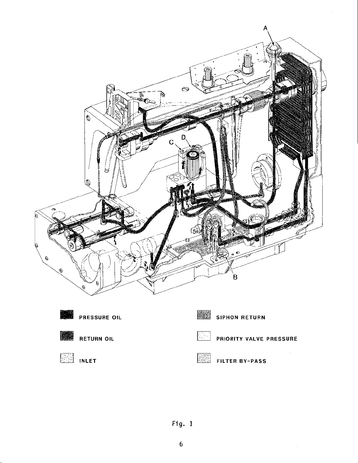
•
PRESSURE
OIL
SIPHON
RETURN
RETURN
OIL
•
GEl
INLET
Fig.
6
I
PRIORITY
FILTER
VALVE
BY-PASS
PRESSURE
Page 7
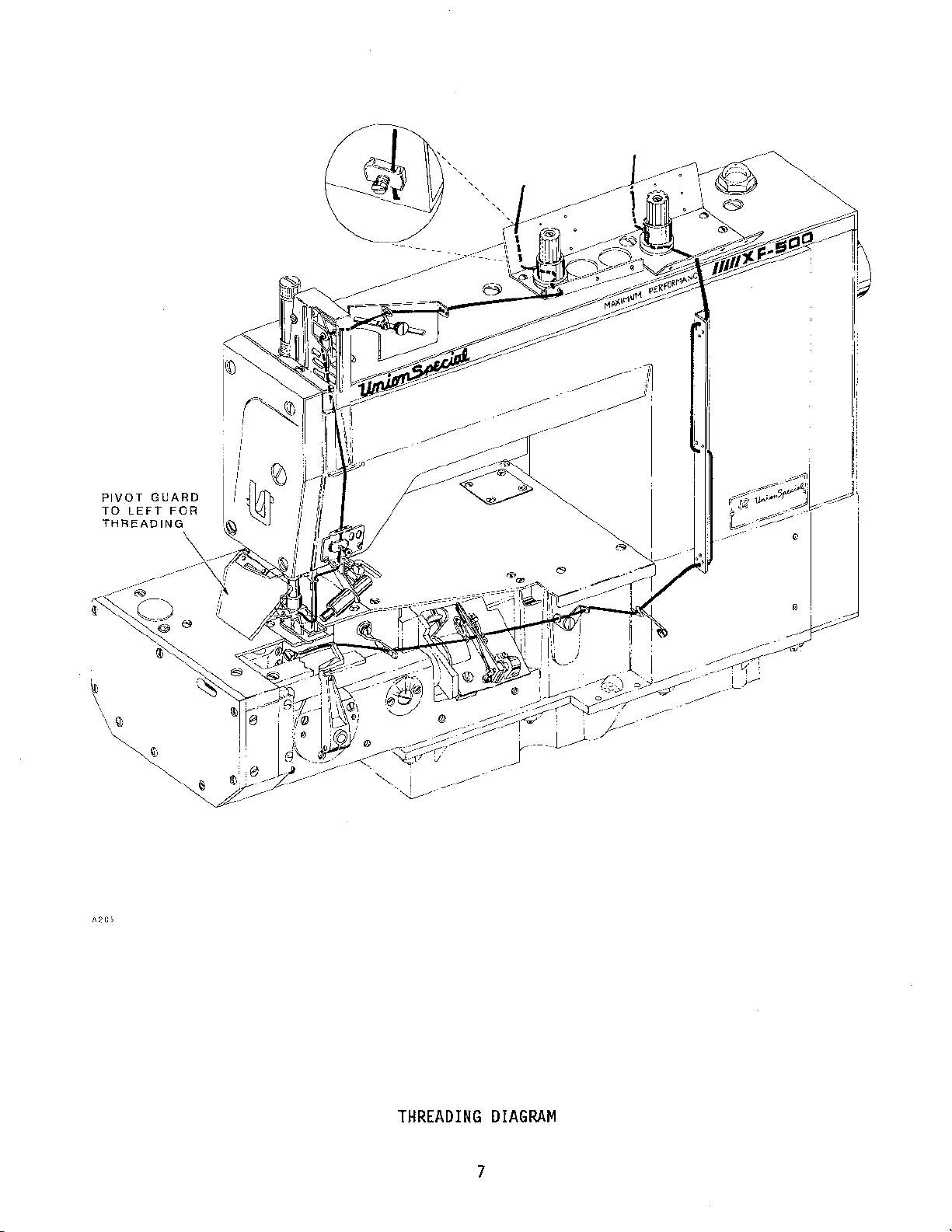
PIVOT
TO
THREADING
GUARD
LEFT
FOR
THREADING
DIAGRAM
7
Page 8
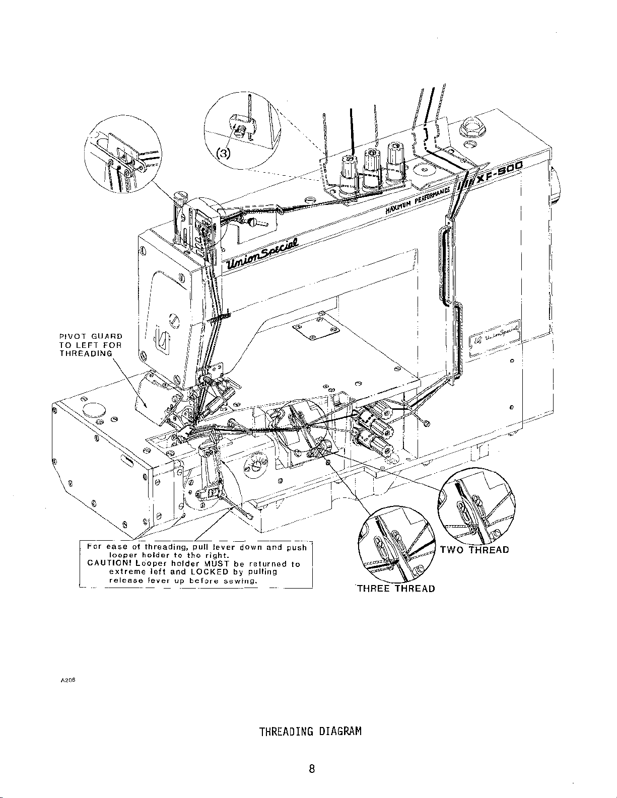
PIVOT
TO
LEFT
GUARD
FOR
r~~~
' '
'
'
-------
---------------------
-
o~ase
AUTION!
r
looper
extreme
release
-----
of
thread1ng,
holder
Looper
left
lever
to
holder
and
up
pull
le~erdow~nd
the
r1ght.
MUST
be
LOCKED
before
by
sewmg.
-----
returnad
pull1ng
THREADING
pu--;,-h-1
to
~·
DIAGRAM
8
Page 9
NEEDLES
Each
shank,
the
needle
point,
needle
has
length,
shank
both
in
between shank and eye.
symbol,
SPECIAL
The
this
available,
satisfactory
their
NEEDLE
108
128
which
CORPORATION.
type
numbers
catalog
but the ones indicated are those
results.
descriptions,
TYPE
GHS
GAS
is
given
of
the
are
given in the machine
and
a
type
groove,
metric,
Co
11
on
needles
The
the
Round
groove,
spotted,
Round
double
eye,
and
size
finish,
denotes
ecti
ve
ly,
the
label
recommended
type
sizes
numbers
available
DESCRIPTION
shank,
struck
shank,
groove,
spotted,
ball
chromium
round
number. Type number
and
other
largest
type and
of
all
style
details.
diameter
size
needles
for
each
description.
recommended
of
the
recommended
are
listed
point,
groove,
plated.
point,
struck
chromium
double
ball
short,
groove,
plated.
eye,
of
number
packaged
Style
below:
ball
denotes
Size
number, stamped
blade,
represent
and
of
machine
the
measured
the
sold
Other needles
to produce the
needles
SIZES
together
AVAILABLE
70/027, 75/029,
80/032, 90/036,
125/049.
80/032, 90/036,
I00/040, 110/044,
125/049, 140/054,
150/060,
170/067.
kind
midway
camp 1 ete
by
UNION
covered
of
on
by
are
most
with
128
GBS
To
have
needle,
label.
The
components
machine.
Adjustments
accomplished.
on
the
NOTE:
needle
or
A
complete
following
function
On
earlier
TORQUE
On
later
bar;
em/kg).
orders
the
type
instructions
related
are
Some
of
Round
double
ball
chromium
promptly
and
order
to
presented
adjustments
other
styles,
shank,
groove,
eye,
size
would
explain
forming
related
machines
spotted,
plated.
and
number
read
the
in
sequence
performed
parts.
round
"1000
needle bar connection screw,
styles,
TORQUE
needle
machines
bar
connection
equipped
point,
struck
ball
accurately
should
needles,
in
detail
stitch
out
equipped
10
with
screw,
short,
groove,
point,
filled,
be
the
and
completing
so
that
of
with
to
12
a
an empty
forwarded.
Type 128
proper
a
sequence
a
DURACOAT
in-lbs.
DURACOAT
16
to
18
80/032, 90/D36,
I00/040, 110/044,
I25/049,
I50/060.
package,
Use
description
GBS,
setting
logical
may
Size
the
functions
have
ALUMINUM
(11.5
to
MASKED
in-lbs.
90/036".
for
progression
adverse
13.8 em/kg).
ALUMINUM
(18.4
140/054,
a sample
each
of
of
effect
needle
needle
to
on
the
the
is
bar;
20.7
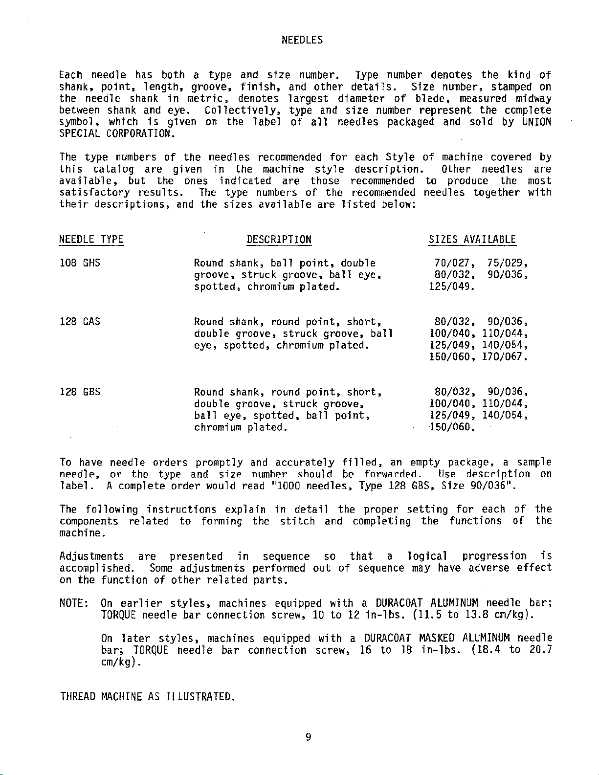
THREAD
MACHINE
AS
ILLUSTRATED.
9
Page 10
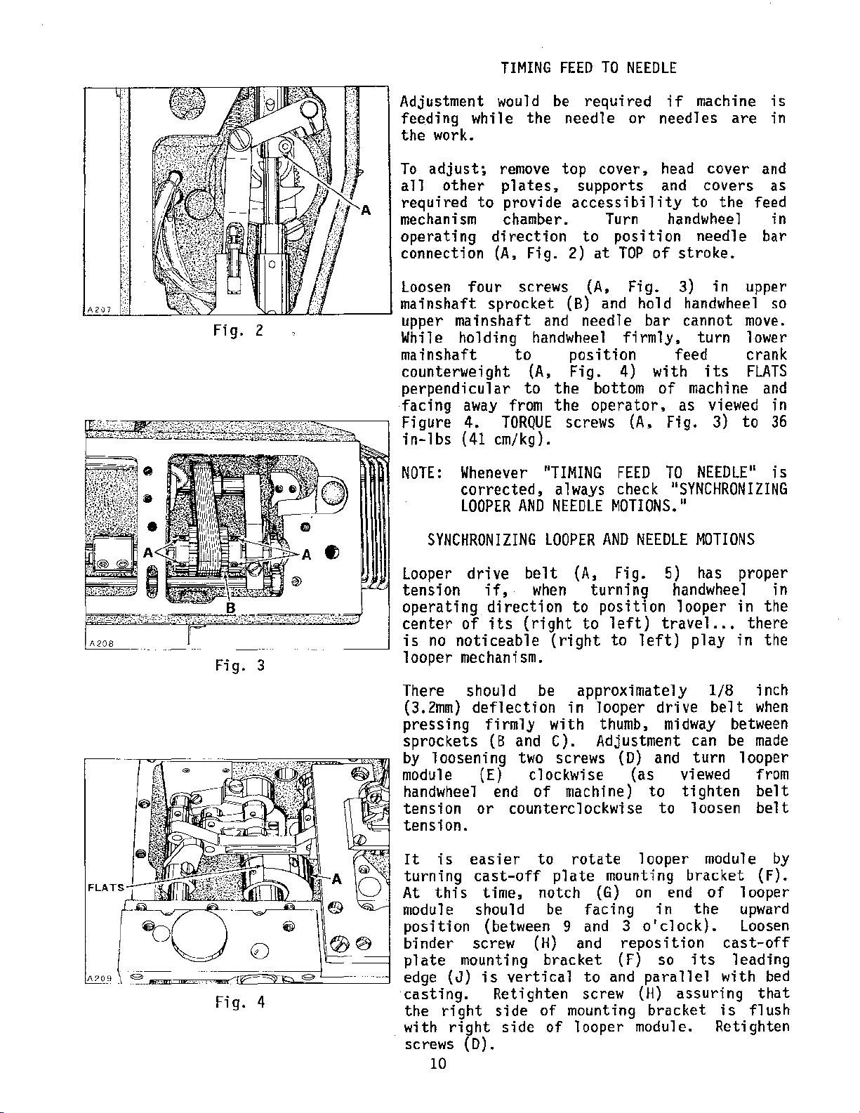
TIMING
FEED
TO
NEEDLE
Fig. 2
Adjustment
feeding
the
work.
To
adjust;
all
other
required
mechanism chamber. Turn
operating
connection
Loosen
mainshaft sprocket
upper mainshaft
While
mainshaft
counterweight
perpendicular
facing
Figure
in-lbs
NOTE:
waul d be
while
to
the
remove
plates~
provide
direction
(A,
Fig.
four screws
holding
handwheel
to
(A,
to
away
4.
(41
from
TORQUE
em/kg).
Whenever
corrected,
LOOPER
AND
required
needle
top
or
cover~
supports
accessibility
to position needle bar
2)
at
TOP
(A,
Fig.
(B)
and
and
needle bar cannot
firmly, turn lower
position
Fig.
the
the
4)
bottom
operator,
screws
"TIMING
always check 11SYNCHRONIZING
NEEDLE
FEED
MOTIONS."
if
needles
head
and
handwhee
of stroke.
3)
hold
feed
with
of
as
(A,
Fig.
TO
machine
are
cover
and
covers as
to
the
feed
1
in upper
handwheel
move.
crank
its
FLATS
machine and
viewed in
3)
to
NEEDLE"
is
in
in
so
36
is
Fig. 3
Fig. 4
SYNCHRONIZING
Looper
tension
operating
center
is
looper
There should be
(3.2mm)
pressing
sprockets
by
module (E)
handwheel end
tension
tension.
It
turning
At
module should
position
binder
plate
edge
casting.
the
with
screws
drive
if,
direction
of
its
no
noticeable
mechanism.
deflection
firmly
(B
loosening
or
is
easier
cast-off
this
screw
mounting
{J)
is
right
right
time,
(between 9
(D).
10
Retighten
side
side
LOOPER
belt
when
(right
and C). Adjustment can
two
clockwise
of
counterclockwise
to
notch
(H)
bracket
vertical
of
of
AND
(A,
Fig.
turning
to
position
to
left)
(right
in
with
screws
machine)
plate
be
mounting
to
approximately
looper
thumb,
rotate
mounting
(G)
facing
and
and
to
and
screw
looper
NEEDLE
5)
handwheel in
looper
travel
left)
drive
midway
(D)
and
(as
on
3
reposition
(F) so
module.
viewed from
to
tighten
to
looper
bracket
end
in
o'clock).
parallel
(H)
assuring
bracket
MOTIONS
has
proper
in
...
there
play
turn
loosen
the
its
in
1/8
belt
module
of
inch
when
between
be
made
looper
belt
belt
(F).
looper
upward
Loosen
cast-off
leading
with
that
is
flush
Retighten
the
the
by
bed
Page 11
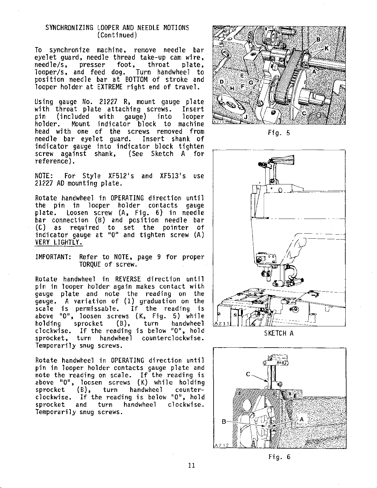
SYNCHRONIZING
To
synchronize machine,
eyelet
needle/s,
looper/s,
position
looper holder
guard,
needle
presser
and feed dog. Turn handwheel
needle
at
LOOPER
AND
(Continued)
thread
foot,
bar
at
BOTTOM
EXTREME
right
NEEDLE
remove
take-up
throat
of
end
MOTIONS
needle bar
cam
wire,
plate,
to
stroke
of
and
travel.
Using
with
gauge
throat
No.
plate
21227
attaching
R,
mount
screws.
pin (included with gauge}
holder.
head
needle
indicator
screw
reference).
NOTE:
21227
Rotate
the
plate.
bar
connection
(C)
indicator
VERY
IMPORTANT:
Rotate
pin
in
gauge
gauge. A
scale
above
Mount
with
AD
one
bar
eyelet
gauge
against
For
mounting
Style
handwheel
pin
as
in
loosen
required
gauge
LIGHTLY.
Refer to
TORQUE
handwheel
looper
plate
is
non,
and
variation
permissable.
loosen
indicator
of the screws
guard.
into
shank,
indicator
{See Sketch A
XF512's
plate.
in
OPERATING
looper
screw (A,
(B) and
at
to
non
holder
position
set
and
NOTE,
of screw.
in
REVERSE
holder
again
note
screws (K. Fig. 5)
of
the
( 1)
block
Insert
and
direction until
contacts
Fig.
the
tighten
page 9 for
direction
makes
reading
graduation
If
the
holding sprocket (B), turn
clockwise.
sprocket,
Temporarily
If
turn
snug
the
reading
handwhee l
screws.
is
below 110
counterclockwise.
gauge
into
to
removed
shank
block
XF513's
6)
in
needle
pointer
screw
contact
reading
handwheel
plate
Insert
looper
machine
from
of
tighten
for
use
gauge
needle
bar
of
(A)
proper
until
with
on
the
on
the
is
while
11
, hold
Fig. 5
J~-·
SKETCH
A
Rotate
pin
note
above
sprocket
clockwise.
sprocket
Temporarily
handwheel
in
looper
the
non,
holder
reading
loosen
(B),
If
and
snug
in
on
turn
the
turn
screws.
OPERATING
contacts
scale.
screws
reading
(K)
handwheel
is
handwheel
direction
gauge
If
the
while
below
until
plate
reading
non,
clockwise.
and
is
holding
counter-
hold
11
Fig. 6
Page 12
A 'o 7
LOOPER IN
FRONT
NEEDLE
SKETCH
B
OF
OPERATING
DIRECTION
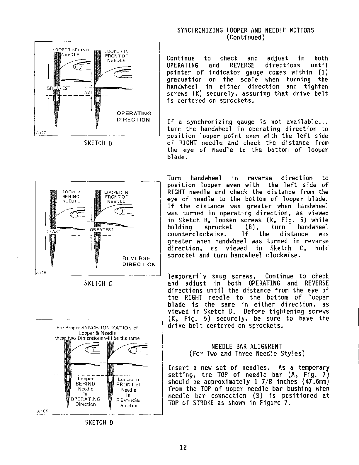
SYNCHRONIZING
Continue
OPERATING
pointer
graduation
handwheel
screws
is
centered
If
a
turn
position
of
the
the
RIGHT
eye
to
and
of
indicator
on
in
-(K)
securely,
on
synchronizing
handwheel
looper
needle
of
needle
blade.
LOOPER
(Continued)
check
and
REVERSE
gauge
the
scale
either
sprockets.
point
and check
direction
assuring
gauge
in
even with
to
AND
NEEDLE
adjust
directions
comes
when
that
is
not
operating
the
the
bottom
MOTIONS
in
within
turning
and
tighten
drive
available
direction
the
left
distance
of
both
until
(1)
the
belt
...
to
side
from
looper
1-
LOOPER
BEHIND
NI::EDl E
For
--·---
---
SKETCH
Proper
SYNCHRONIZATION
Looper & Needle
Dimensions
LOOPER IN
FRONT
OF
NE:EDLE
REVERSE
DIRECTION
C
will
be
the same
---
of
Turn handwheel
position
RIGHT
of
eye
If
the
was
turned
in
Sketch
looper
needle
needle
distance
in
B,
in
even
and check
to
the
was
operating
loosen
screws (K, Fig. 5) while
reverse
with
the
bottom
greater
direction,
direction
the
left
distance
of
looper
when
holding sprocket (B), turn
counterclockwise.
greater
direction,
sprocket
when
and
handwheel
as
turn
Temporarily snug screws. Continue
and
adjust
directions
the
RIGHT
blade
viewed
(K,
drive
is
in
Fig.
belt
in both
until
needle
the
same
Sketch
5)
securely,
centered
NEEDLE
(For
Two
and
If
viewed
handwheel
the
distance
to
in
D.
Before
on
BAR
Three
the
was
in
distance
turned
Sketch
clockwise.
OPERATING
and
from
the
bottom
either
direction,
tightening
be
sure
to
sprockets.
ALIGNMENT
Needle
Styles)
side
from the
blade.
handwheel
as
viewed
handwheel
in
reverse
C,
hold
to
check
REVERSE
the
eye
of
looper
screws
have the
to
of
was
of
as
Looper
BEHIND
Needle
in
SKETCH
Looper in
FRONT
Needle
REVERSE
Dirroction
D
io
of
Insert
setting,
should
from
needle
TOP
a
be
the
of
STROKE
new
the
approximately 1 7/8 inches
TOP
bar
connection
12
set
TOP
of
as
of
needles.
of needle bar
upper
shown
needle
(B)
in
Figure
As
bar
bushing
is
positioned
7.
a temporary
(A,
Fig. 7)
(47.6mm)
when
at
Page 13
NEEDLE
(For
Two
BAR
ALIGNMENT
and
Three Needle
(Continued)
Styles)
----
-,
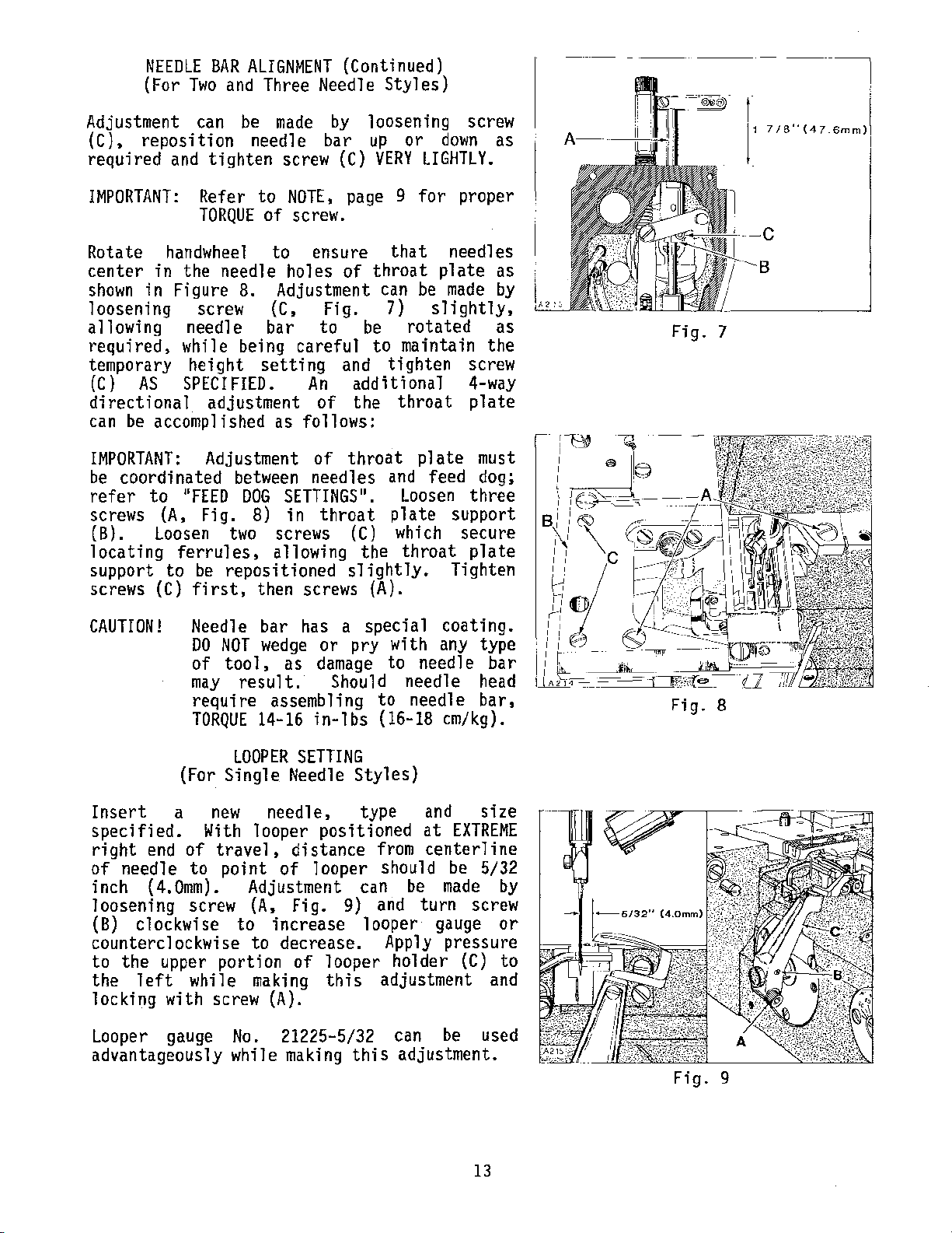
Adjustment can
(C)~
required
reposition
and
IMPORTANT:
Rotate
center
shown
handwheel
in the needle holes
in
Figure
loosening screw
allowing needle bar
be
needle bar
tighten
Refer to
TORQUE
of
8.
made
screw
by
NOTE,
(C)
page 9
screw.
to
ensure
of
Adjustment
(C,
Fig.
to
loosening screw
up
or
VERY
that
throat
can
7)
be
down
LIGHTLY.
for
plate
be
made
slightly,
rotated
as
proper
needles
as
by
as
requireds while being careful to maintain the
temporary height
(C)
directional
can
IMPORTANT:
be
refer
screws (A,
(B).
locating
support to
screws
AS
SPECIFIED.
adjustment of the
be
accomplished as follows:
Adjustment
coordinated
11
to
loosen
ferrules,
FEED
Fig.
be
(C)
first,
setting
An
of
between
DOG
8)
two
needles
SETTINGS
in
throat
screws (C) which
allowing
repositioned
then screws
and
tighten
additional
throat
throat
and
11
•
Loosen
plate
the
throat
slightly.
{A).
plate
feed
support
Tighten
screw
4-way
plate
must
dog;
three
secure
plate
Fig. 7
l'
'18
-C
(4
7
6mm)l
CAUTION!
Needle bar has a special coating.
DO
NOT
of
may
wedge
tool,
result.
or pry with
as
damage
Should needle
require assembling to needle
TORQUE
(For Single Needle
Insert
specified.
right
of
needle to point of looper should
inch
a
With
end
of
(4.0mrn).
loosening screw
(B)
clockwise to increase looper gauge
LOOPER
new
14-16
needle, type
in-lbs
SETTING
looper positioned
travel,
distance
Adjustment can
(A,
Fig. 9)
Styles)
from
and
counterclockwise to decrease.
to the upper portion
the
left
while
of
making
looper holder
this
locking with screw (A).
Looper
advantageously while
gauge
No.
21225-5/32 can
making
this
any
type
to needle bar
head
bar,
(16-18 em/kg).
and
at
size
EXTREME
centerline
be
5/32
be
made
turn screw
Apply
pressure
(C)
adjustment
be
and
used
adjustment.
by
or
to
Fig. 8
Fig.
9
13
Page 14
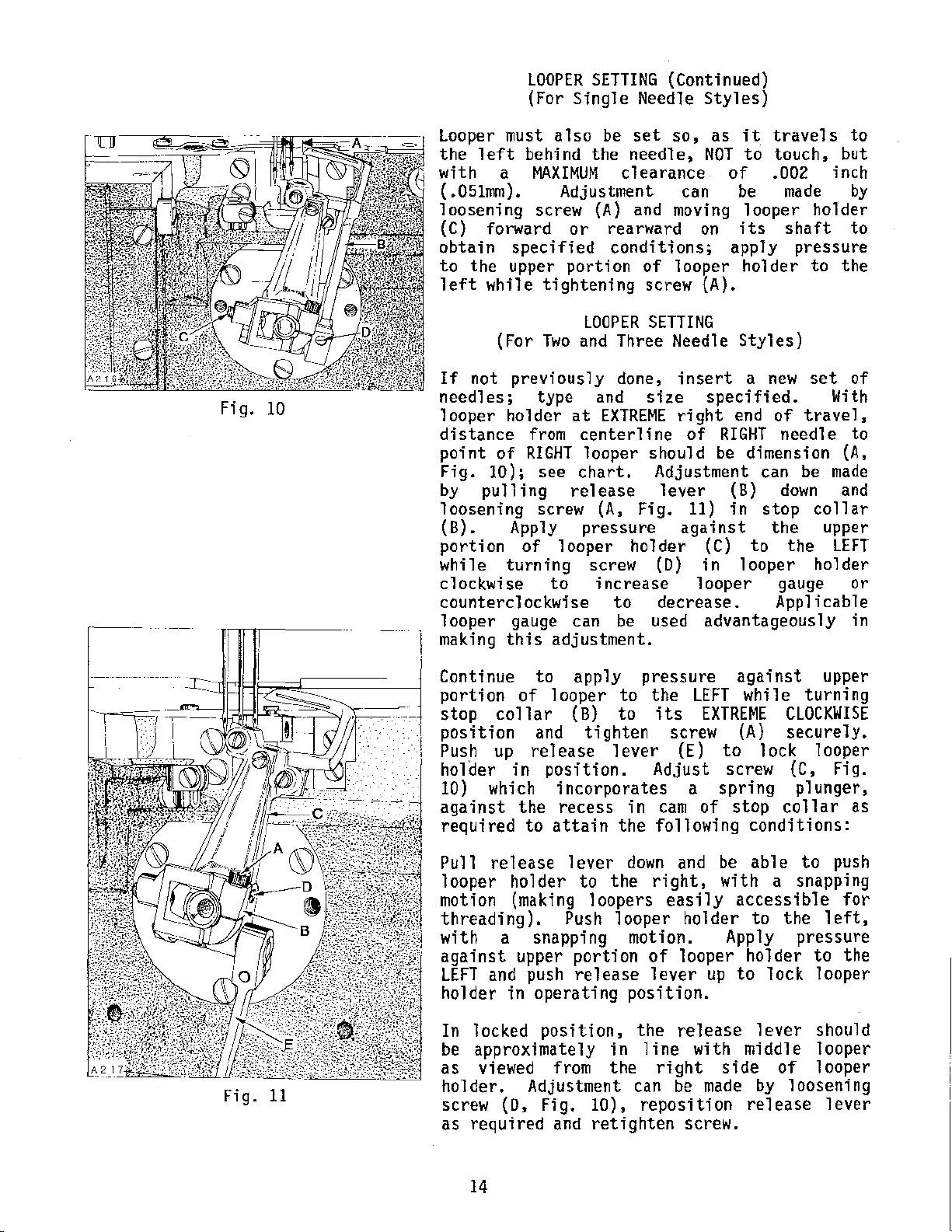
LOOPER
SETTING
(Continued)
(For Single Needle Styles)
Fig.
10
looper
the
with
(.051mm).
loosening screw
(C)
must
left
a
also
behind the needle,
MAXIMUM
Adjustment
forward
or
be
set
clearance
{A)
and
rearward
so, as
NOT
can
moving
on
it
travels
to
touch, but
of
.002 inch
be
made
looper holder
its
shaft
to
by
to
obtain specified conditions; apply pressure
to
the
upper
left
while tightening screw (A).
(For
If
not
previously
needles;
looper holder
distance
point
Fig.
by
loosening
(B).
of
10);
pulling
Apply
portion
while turning screw
clockwise
counterclockwise
looper
making
gauge can
this
portion
LOOPER
Two
and
type
from
RIGHT
see
and
at
EXTREME
centerline
looper should
chart.
release
screw
(A,
pressure
of
looper holder
to
increase looper
adjustment.
of
looper
holder
SETTING
Three Needle Styles)
done,
insert
size
right
of
Adjustment
lever
Fig.
11)
against
(C)
(D)
in looper holder
a
new
specified.
end
of
RIGHT
be
(B)
in
needle
dimension
can be
down
stop
the upper
to
the
gauge
to
be
decrease.
used
advantageously
Applicable
to
the
set
of
With
travel,
to
(A,
made
and
collar
LEFT
or
in
Fig.
11
Continue
portion
stop
position
Push
holder
10) which
against
required
Pull
looper
motion (making
threading).
with
against
LEFT
and push
holder
In locked
be
approximately
as
viewed from
holder.
screw
as
required
to
of
looper
collar
and
up
release
in
position.
incorporates
the
recess
to
attain
release
holder
Push
a snapping motion. Apply
upper
in
operating
position,
Adjustment can
(D~
Fig.
and
apply
to
(B)
to
tighten
lever
in
the
lever
to
down
the
loopers
looper holder
portion
release
position.
the
in
the
10),
retighten
pressure
the
LEFT
its
Adjust
following
right,
of
lever
line
reposition
EXTREME
screw
(E)
a
spring
cam
of
and
be
easily
looper
up
release
with middle
right
be
made
screw.
against
while
upper
turning
CLOCKWISE
(A)
to
screw (C, Fig.
stop
with
accessible
to
side
securely.
lock
conditions:
able
to
holder
lock
lever
by
release
looper
plunger,
collar
to
a snapping
the
left,
pressure
to
looper
should
looper
of
looper
loosening
lever
push
for
the
as
14
Page 15
LOOPER
(For
Two
SETTING
and
Three Needle Styles)
(Continued)
Loopers must
to the
but
(.051mm).
release
11)
to
as
portion
left
with
lever
in stop
be
moved
required.
of
behind the
a
Adjustment
collar
forward
looper
turning stop
CLOCKWISE
securely
position.
position
and
RECHECK
MACHINE
XF512EJOOHB-1
XF512E100MP-12
XF512EJOOMP-16
XF513EJOOHJ-8
XF513E100HJ-9
XF513E100HR-9
XF513E101HR-9
XF513Ell2HR-9
also
MAXIMUM
be
down,
(B)
Apply
holder
collar
push
release
looper gauge.
STYLE
set
so,
as
they
needles~
c 1
ea
ranee
can
be
loosening
NOT
to
of
. 002 inch
made
by
screw {A, Fig.
allowing looper holder
or rearward
pressure
to
(B)
and
tighten screw
lever
against
the
to
on
its
LEFT
its
up
in locking
DIMENSION A FIG.
5/32 inch
1/8 inch
1/8 inch
5/32 inch
5/32 inch
5/32 inch
5/32 inch
5/32 inch
travel
touch,
pulling
shaft,
upper
while
EXTREME
(A)
10
(4.0mm)
(3.2mm)
(3.2mm)
(4.0mm)
(4.0mm)
(4.0mm)
(4.0mm)
(4.0mm)
Fig.
LOOPER
GAUGE
21225-5/32
21225-1/8
21225-1/8
21225-5/32
21225-5/32
21225-5/32
21225-5/32
21225-5/32
12
NO.
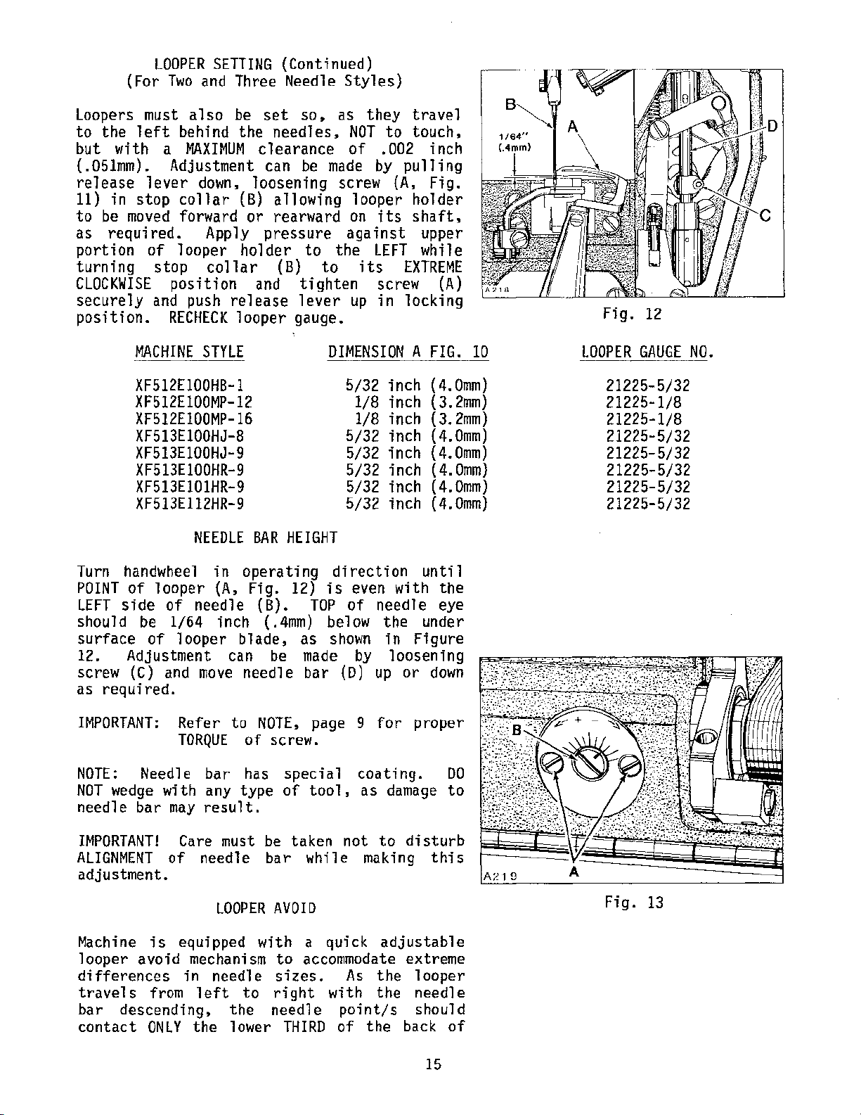
NEEDLE
Turn
POINT
LEFT
should
surface
12. Adjustment
screw
as required.
IMPORTANT:
handwhee 1
of
looper
side
be
of
(C)
of
1/64 inch
looper
and
Refer to
needle (B).
move
TORQUE
NOTE:
NOT
needle
IMPORTANT!
ALIGNMENT
adjustment.
Machine
looper
differences
tra
bar
contact
Needle bar
wedge
bar
with
may
Care must be taken
of
is
equipped
avoid
ve 1 s from 1
descending.
ONLY
mechanism
in
the
BAR
HEIGHT
in
operating
(A,
Fig.
12)
direction
is
TOP
blade,
can
needle
(.4mm)
be
NOTE,
below
as
made
bar
page
shown
of screw.
has
special
any
type
result.
of
tool,
needle bar while
LOOPER
needle
eft
the
lower
with
to
AVOID
a
quick
to
accommodate extreme
sizes.
right
needle
THIRD
with
point/s
of
even
of
needle
by
(D)
up
9
for
coating.
as
not
to
making
As
the
the
the
unt
i1
with the
eye
the under
in
Figure
loosening
or
down
proper
DO
damage
disturb
to
this
adjustable
looper
needle
should
back
of
Fig.
13
15
Page 16
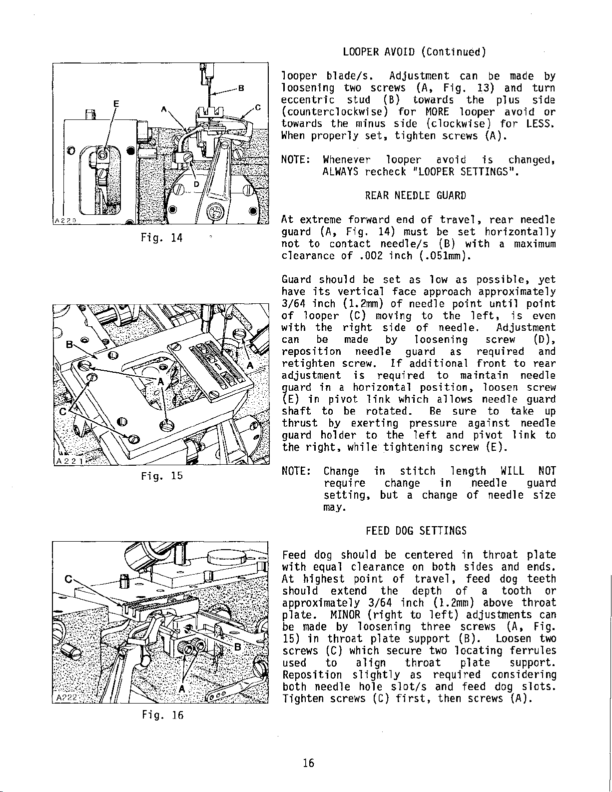
LOOPER
AVOID
(Continued)
Fig.
14
looper
loosening
eccentric
(counterclockwise)
towards
When
NOTE:
At
guard (A,
not
clearance
Guard
have
3/64
of
with
can
reposition
retighten
adjustment
!1uard
{E)
shaft
thrust
guard
the
blade/s.
two
screws
stud
the
minus
properly
set,
Whenever
ALWAYS
recheck
REAR
extreme forward
Fig.
to
contact
of
.002
should
its
inch
looper
the
be
in a horizontal
in
pivot
to
by
ho 1 der
right,
be
vertical
(1.2mm)
(C) moving
right
made
needle
screw.
is
link
be
rotated.
exerting
to
while
Adjustment
(A,
(B)
towards the plus side
for
MORE
side
tighten
looper
NEEDLE
"LOOPER
end
of
{clockwise)
avoid
GUARD
14) must be
needle/s
inch
set
face
of
side
by
(B)
(.051mm).
as
low
approach
needle
to
of
needle.
loosening screw (D),
guard
If
additional
required
to
position,
which
allows
Be
pressure
the 1 eft
tightening
can be
Fig.
screws (A).
13) and
looper
is
SETTINGS".
travel,
set
as
rear
horizontally
with
possible,
approximately
point
the
as
until
left,
required
front
maintain
loosen screw
needle
sure
to
against
and
pi
vat 1 ink.
screw
(E).
made
avoid
for
by
turn
or
LESS.
changed,
needle
a
maximum
yet
point
is
even
Adjustment
and
to
rear
needle
guard
take
up
needle
to
Fig.
Fig.
15
16
NOTE:
Change
require
setting,
may.
Feed
with equal
At
dog
highest
should
clearance
point
should extend
approximately
plate.
be
15)
screws
used
Reposition
both
made
in
needle
MINOR
by
throat
(C)
which
to
loosening
align
slightly
hole
Tighten screws
in
change
but
FEED
be
the
3/64
(right
plate
secure
(C)
stitch
a change
DOG
SETTINGS
centered
on
of
travel,
depth
inch
to
support
throat
as
slot/s
first,
1
ength
in
needle
of
in
both
sides
feed dog
of
(1.2mm) above
left)
three
two
adjustments
screws (A, Fig.
(B).
locating
plate
required
and feed
then
screws {A).
WILL
guard
needle
throat
plate
and ends.
teeth
a
tooth
throat
Loosen
ferrules
support.
considering
dog
slots.
NOT
size
or
can
two
16
Page 17
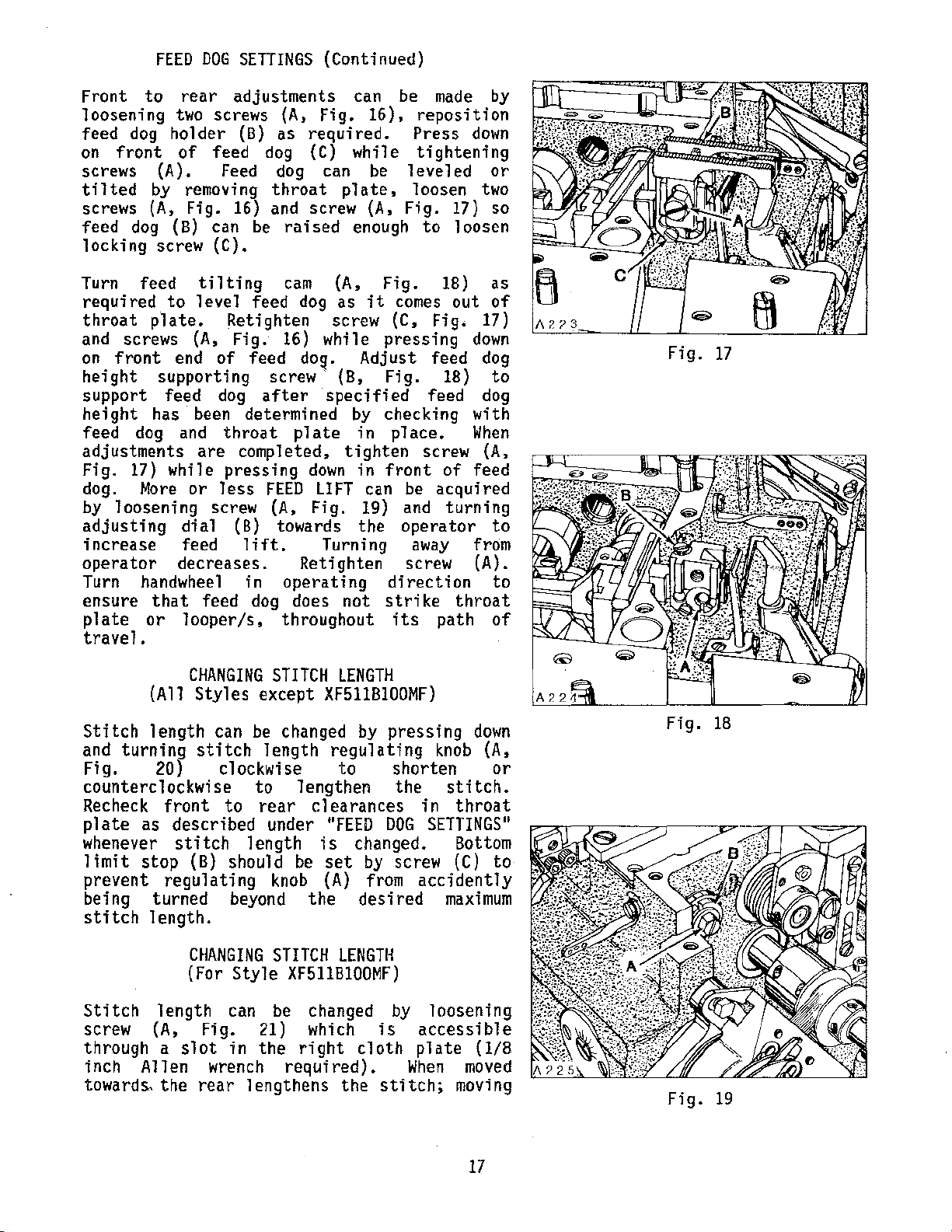
FEED
DOG
SETTINGS
(Continued)
Front
loosening
feed
on
screws
tilted
screws
feed
locking
Turn
required
throat
to
dog
front
dog
feed
rear
two
holder
of
(A).
by
(A,
(B) can
screw
to
plate.
removing
Fig.
tilting
level feed
and screws (A,
on
front
height
end
supporting
support feed
height
feed
adjustments
Fig.
dog.
by
adjusting
increase
operator
Turn handwheel
ensure
plate
travel.
has been
dog and
17)
while
More
loosening
dial
feed
decreases.
that
or
looper/s,
are
or
screw (A,
feed
adjustments
screws
feed
Feed
16)
(C).
Retighten
Fig.
of
dog
throat
pressing
less
{A,
(B)
as
dog (C)
dog
throat
and
be
raised
cam
16)
feed
screw·
after
determined
completed,
FEED
(B)
towards
lift.
in
operating
dog
throughout
can
Fig.
required.
while
can
plate,
screw
enough
(A,
dog
as
screw
while
dog.
(B,
specified
by
plate
tighten
down
LIFT
Fig.
Turning
Retighten
does
not
be
16),
be
leveled
(A,
Fig.
Fig.
it
comes
(C,
pressing
Adjust
Fig.
checking
in
place.
in
front
can
be
19) and
the
operator
screw
direction
strike
its
made
by
reposition
Press
tightening
down
or
loosen
to
Fig.
feed
feed
screw (A,
17)
1 oosen
18)
out
down
18)
with
When
of
feed
two
so
as
of
17)
dog
to
dog
acquired
turning
to
away from
(A).
to
throat
path
of
Fig.
17
(All
Stitch
and
Fig.
counterc
Recheck
plate
whenever
limit
prevent
being
stitch
Stitch
screw
through
inch A 11
towards.
length
turning
as
stop
turned
length.
{A,
CHANGING
Styles
can be changed by
stitch
20)
1 ockwi
front
described
regulating
length
a
en wrench
the
clockwise
se
to
stitch
(B)
CHANGING
(For
Fig.
slot
rear
STITCH
except
length
to 1 engthen
rear
under
length
should
knob (A) from
beyond
STITCH
Style
can be changed by
in
XF511B100MF)
21) which
the
required).
lengthens
LENGTH
XF511B100MF)
regulating
to
clearances
"FEED
is
changed.
be
set
by
the
right
desired
LENGTH
cloth
the
pressing
shorten
the
DOG
screw
is
stitch;
knob (A,
stitch.
in
throat
SETTINGS
Bottom
(C)
accidently
maximum
loosening
accessible
plate
When
moved
moving
down
or
to
(1/8
Fig.
11
Fig.
18
19
17
Page 18
CHANGING
(For
STITCH
Style
LENGTH
XF511B100MF)
(Continued)
towards the
plate
Tighten
as described under 11FEED
screw
front
(A)
Fig.
acts
securely.
the
20
reverse.
DOG
Recheck
SETTINGS
(For
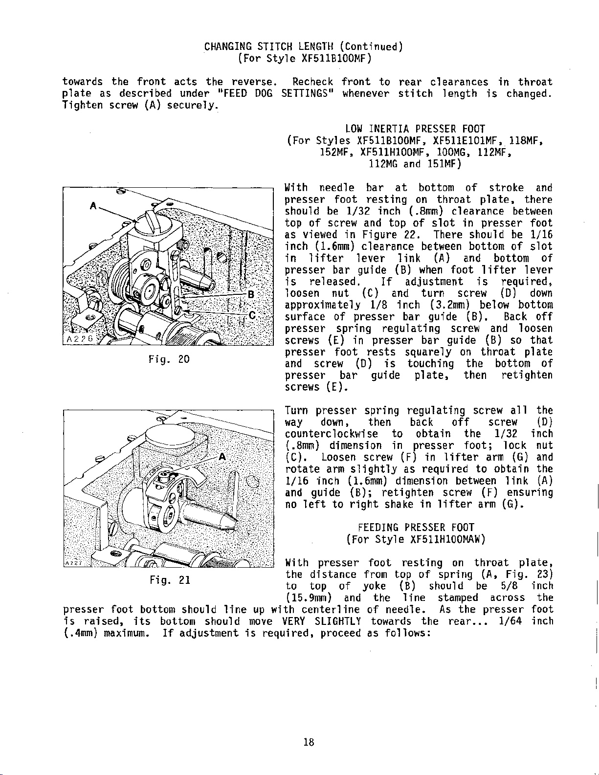
With
presser
should
top
of
as
viewed
inch
in
lifter
presser
is
released.
loosen
approximately
surface
presser
front
11
whenever
LOW
Styles
152MF,
needle
foot
be
1/32
screw
in Figure 22.
(1.6mm)
bar
nut
of
spring
screws (E) in
presser
and
presser
screws
foot
screw
bar guide
(E).
to
rear clearances in
stitch
INERTIA
XF51IB100MF, XF511E101MF, 118MF,
XF511H100MF,
112MG
bar
and
at
resting
inch ( .8mm)
and
top
of
length
PRESSER
100MG,
151MF)
bottom
on
throat
clearance
slot
There
is
FOOT
112MF,
of
plate,
in presser foot
should
clearance between bottom
lever
guide
(C) and
presser
rests
(D)
link
(B)
If
adjustment
1/8
inch
bar
regulating
presser
squarely
is
touching
(A) and
when
turn
foot 1 ifter
(3.2mm)
guide (B).
screw
bar guide
plate,
is
screw
below
on
the
then
(B)
throat
throat
changed.
stroke
there
between
be
of
bottom
1 ever
required,
(D)
bottom
Back
and
loosen
so
plate
bottom
retighten
1/16
slot
down
that
and
of
off
of
-.--;
presser foot
is
raised,
(.4mm)
maximum.
Fig.
21
bottom
its
should
bottom should
If
adjustment
line
Turn
way
counterclockwise
(
(C).
rotate
1/16
and
no
With
the
to
(15.9mm)
up
with centerline
move
is
VERY
required, proceed as follows:
presser
down.
.8mm)
Loosen
inch
guide
left
presser
distance
top
SLIGHTLY
spring
then
dimension in
screw
arm
slightly
(1.6mm)
to
(B);
right
(For
retighten
shake
FEEDING
Style
foot
from
of
yoke (B)
and
the
of
needle.
towards the rear
to
regulating
back
off
obtain the
presser
(F)
in
lifter
as required
dimension
screw
in
lifter
PRESSER
XF511H100MAW)
resting
top
of
line
FOOT
on
spring
should
stamped
As
screw a
foot;
arm (G) and
to
between
(F)
arm
throat
(A,
be
11
the
screw
l/32
(D)
inch
lock nut
obtain the
link
ensuring
(G).
Fig.
5/8
(A)
plate,
23)
inch
across the
the presser foot
...
1/64 inch
18
Page 19
FEEDING
(For
PRESSER
Style
FOOT
XF511HIOOMAW)
(Continued)
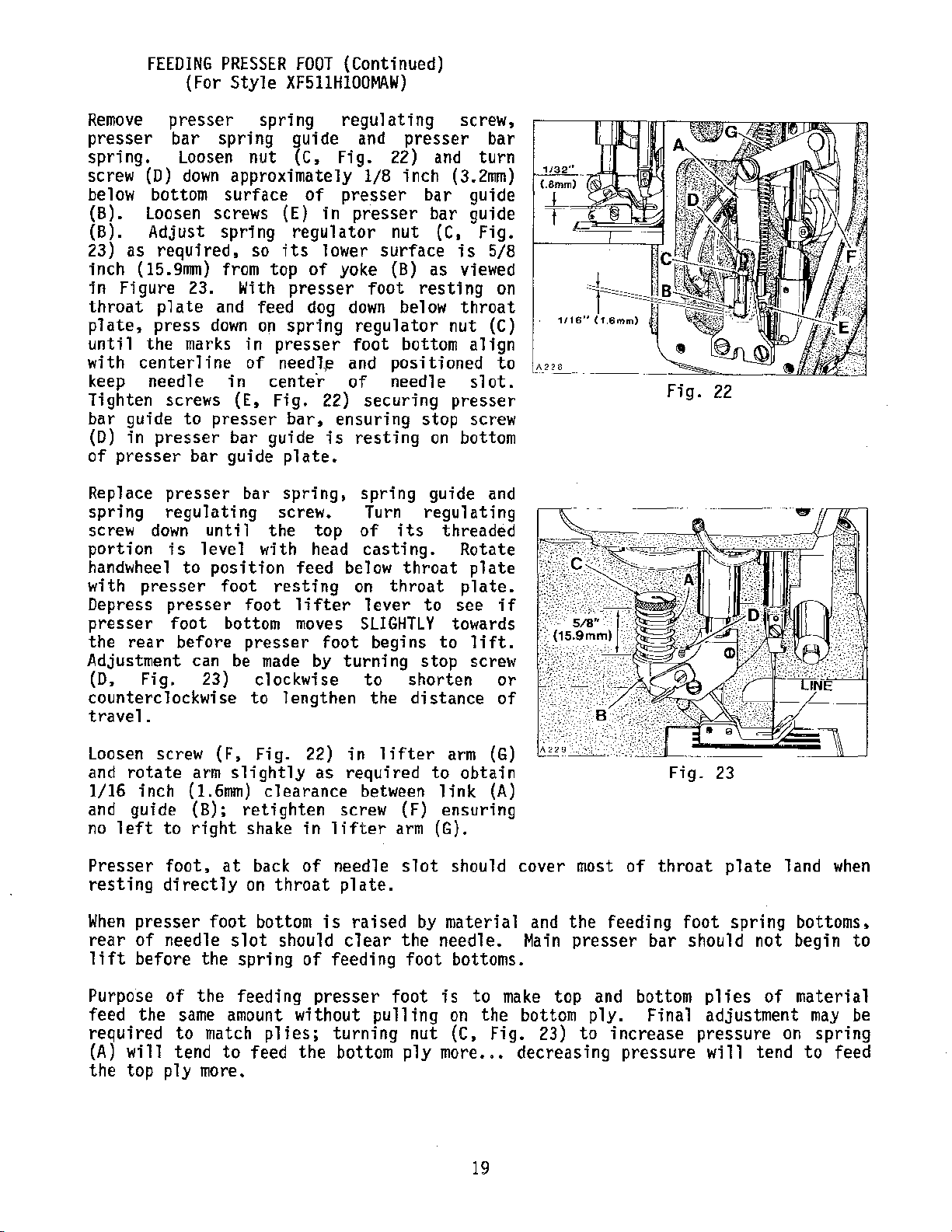
Remove
presser spring regulating screw,
presser bar spring guide
spring.
screw
below
(B).
(B).
23) as
inch
in
Figure 23.
throat
plate,
until
with
keep needle
Tighten
bar
guide
(D)
in
of
presser
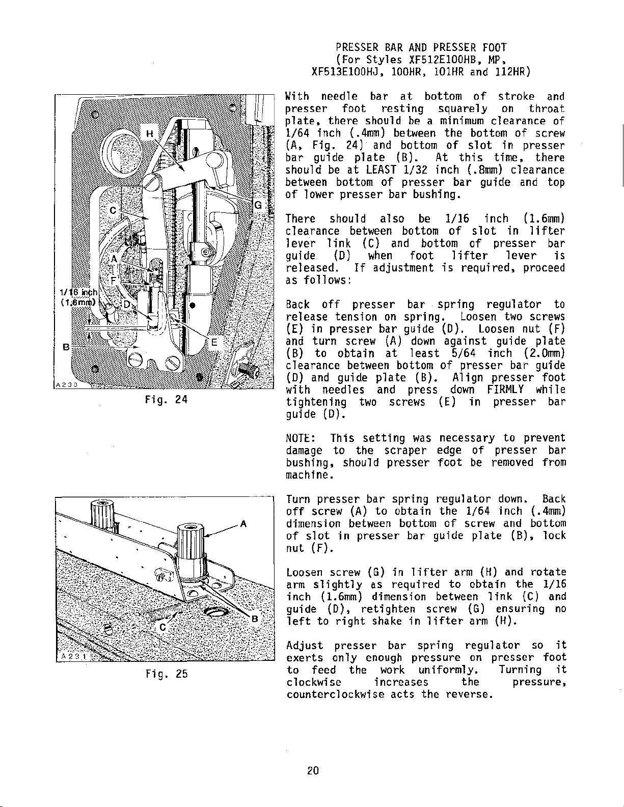
Replace
spring
screw
portion
handwheel
with
Depress
presser
the
rear
Adjustment can
(D,
counterc 1 ockwi
travel.
(D)
Loosen
down
nut
approximately
bottom surface
Loosen screws (E)
Adjust
required,
(15,gmm) from
spring
so
its
top
With
plate
press
the
centerline
screws
presser
and feed
down
marks
to
presser
in
(E,
bar
on
in
presser
of
needl,e and pas
cente·r
Fig.
guide
bar guide
presser
regulating
down
is
to
presser
presser
foot
before
Fig.
bar
until
level
position
foot
foot
bottom
presser
be
23)
se
to
spring,
screw.
the
with head
resting
made
clockwise
1 engthen the
( C,
of
in
regulator
1 ower
of
presser
dog
spring regulator nut
22)
bar,
is
plate.
top
feed below
lifter
moves
foot
by
and
presser bar
Fig.
22) and
1/8
inch
turn
(3.2mm)
presser bar guide
presser
surface
yoke (B)
foot
down
nut
resting
below
bar
(C,
as
guide
Fig.
is
5/8
viewed
throat
(C)
foot
of
ensuring
on
turning
bottom
iti
needle s 1
securing
stop
resting
spring
Turn
of
on
guide
regulating
its
casting.
throat
throat
lever
to
SLIGHTLY
begins
stop
to
shorten
distance
align
oned
at.
presser
screw
bottom
and
threaded
Rotate
plate
plate.
see
towards
to
lift.
screw
on
to
if
or
of
1116"
1.6mm)
Fig.
22
Loosen screw
and
rotate
1/16
and
no
inch
guide
left
Presser
resting
When
rear
lift
presser
of
before
Purpose
feed the
required
(A)
wi
11
the
top ply more.
arm
(1.6mm)
(B);
to
right
foot,
directly
needle
of
same
to
tend
(F,
Fig.
slightly
clearance
retighten
shake
at
back
on
throat
foot
bottom
slot
the
the
should
spring
feeding
amount without
match
to
plies;
feed
22)
in
lifter
as
required
between
screw (F)
in
of
lifter
needle
arm (G).
slot
plate.
is
clear
of
feeding
presser
raised
by
the
foot
foot
pulling
turning
the
bottom p 1 y more. . •
nut (C, Fig. 23)
arm
(G)
to
obtain
link
ensuring
(A)
should cover most
material
needle.
bottoms.
is
to
on
the bottom
and
Main
make
top
decreasing
19
the
feeding
presser
and
ply.
to
increase
of
Fig.
throat
foot
23
plate
spring
bar should not begin
bottom
plies
of
Final adjustment
pressure
pressure
wi
11
tend
land
when
bottoms,
material
may
on
spring
to
feed
to
be
Page 20
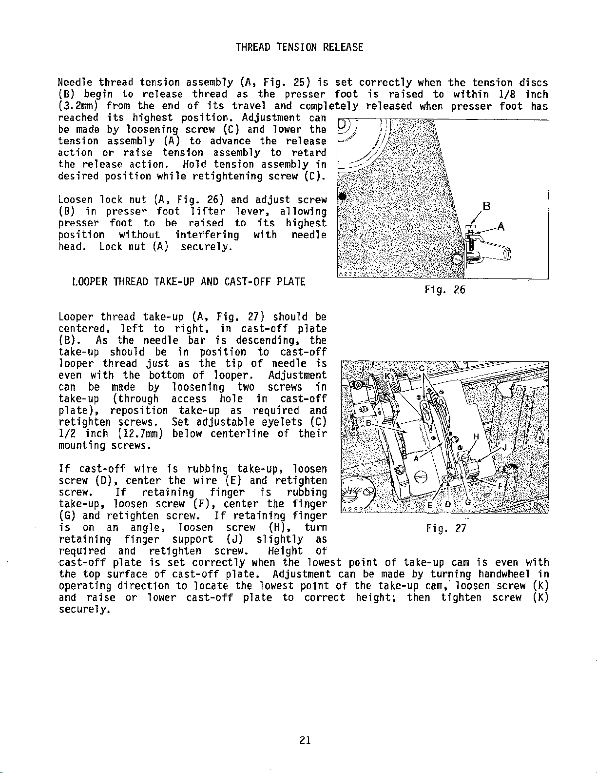
PRESSER
(For
Styles
XF513E100HJ,
BAR
AND
PRESSER
XF512E100HB,
100HR,
101HR
FOOT
and
MP,
112HR)
Fig.
24
With
presser
plates
1/64
(A,
bar guide
should
between bottom
of
There should
clearance
lever
guide (D)
released.
as
Back
release
(E)
and
(B)
needle bar
foot
there
inch
Fig.
lower
24) and bottom
be
at
presser
link
follows:
off
tension
in
presser
turn
to
screw
obtain
at
resting
should
(.4mm) between
plate
LEAST
be a minimum
(B).
1/32 inch
of
presser
bar bushing.
also
be
between bottom
(C) and bottom
when
If
adjustment
presser
foot
bar spring
on
spring.
bar guide (D).
(A)
down
at
least
clearance between bottom
(D)
and
with
tightening
needles
guide
two
plate
and
screws
(B). Align
press
guide (D).
bottom
squarely
the
of
At
this
bar
1/16 inch
of
lifter
is
requireds
Loosen
against
5/64 inch
of
presser
down
(E)
of
stroke
on
clearance of
bottom
slot
in
time,
(.Bmm)
slot
of
clearance
guide
in
presser
lever
regulator
two
Loosen
guide
bar guide
presser
FIRMLY
in
presser
throat
of
screw
presser
there
and
(1.6mm)
lifter
proceed
screws
nut (F)
plate
(2.0mm)
foot
while
and
top
bar
is
to
bar
Fig.
25
NOTE:
damage
bushing.
machine.
Turn
off
dimension
of
nut
Loosen screw (G)
arm
inch
guide
left
Adjust
exerts
to
clockwise
counterclockwise
This
presser
screw
slot
(F).
slightly
(1.6mm) dimension between
{D),
to
only
feed
setting
to
the
should
bar
(A)
to
between bottom
in
presser
as
retighten
right
presser
shake in
enough
the
increases
was
necessary
scraper
presser
spring
edge
foot
regulator
of
be removed from
obtain the 1/64 inch
of
screw
bar
in
required
bar
work
acts
guide
lifter
screw
lifter
spring
pressure
uniformly.
the
plate
arm (H) and
to
obtain
(G)
arm
regulator
on
the
reverse.
to
prevent
presser
down.
and bottom
{B).
the
link
(C) and
ensuring
(H).
presser
Turning
pressure,
bar
Back
(.4mm)
lock
rotate
1/16
no
so
it
foot
it
20
Page 21
THREAD
TENSION
RELEASE
Needle
{B)
(3.2mm)
reached
be
tension
action
the
thread tension assembly
begin
made
release
to
release
from
its
by
assembly
or
the
end
highest
loosening screw
raise
action.
position.
(A)
tension
thread
of
to
Hold
(A,
as
its
travel
Adjustment can
(C)
advance
assembly
tension
Fig.
the
and
and
lower the
the
to
assembly
25)
is
presser
completely
release
retard
in
desired position while retightening screw (C).
Loosen
(B)
presser foot to
position
head.
Looper
centered,
(B).
take-up should
looper
even
can
take-up
plate),
retighten
l/2
lock
in
nut
presser
(A,
foot
be
without
Lock
nut
(A)
LOOPER
THREAD
thread
left
As
the
TAKE-UP
take-up
to
needle
be
thread
with
be
made
{through
the
just
bottom
by
reposition take-up as required
screws.
inch (12.7mm) below
Fig.
26) and
lifter
raised
interfering
securely.
AND
(A,
Fig.
right,
bar
is
in
position
as
the
of 1 caper.
loosening
access
Set
adjustable
centerline
adjust
lever,
to
its
with
CAST-OFF
27) should
in
cast-off
descending,
to
tip
of
Adjustment
two
hole
screws
in
eyelets
screw
allowing
highest
needle
PLATE
plate
cast-off
needle
cast-off
of
their
be
the
is
in
and
(C)
mounting screws.
set
foot
correctly
is
raised
released
when
to
when
Fig.
the tension discs
within 1/8 inch
presser
26
foot
has
If
cast-off
screw
screw.
take-up,
(G)
is
retaining
required
cast-off
the
operating
and
securely.
(D),
and
on
top
raise
wire
center
If
retaining
loosen screw
retighten
an
angle,
finger
and
plate
surface
direction
or
retighten
is
of
1 ower
is
rubbing
the
wire
(F),
screw.
loosen
support
set
correctly
cast-off
to
locate
cast-off
take-up,
(E) and
finger
center
If
retaining
screw
(J)
screw. Height
plate.
the
p 1
retighten
is
rubbing
the
(HL
slightly
when
the
Adjustment can
lowest
ate
to
loosen
finger
finger
turn
as
of
lowest
point
correct
21
point
of
of
be
made
the
take-up
height;
Fig.
take-up
by
turning
cam,"
then
27
cam
is
handwheel
loosen screw
tighten
even with
in
(K)
screw (
K)
Page 22
(For
Styles
XF511BIOOMF,
THREAD
CONTROL
XF511EIOIMF,
112MG
118MF,
and
151MF)
SETTINGS
152MF,
XF511HIOOMF,
MG,
MAW,
112MF,
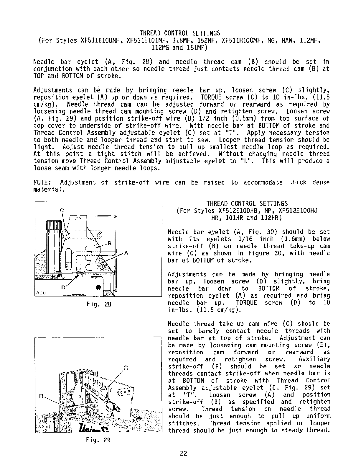
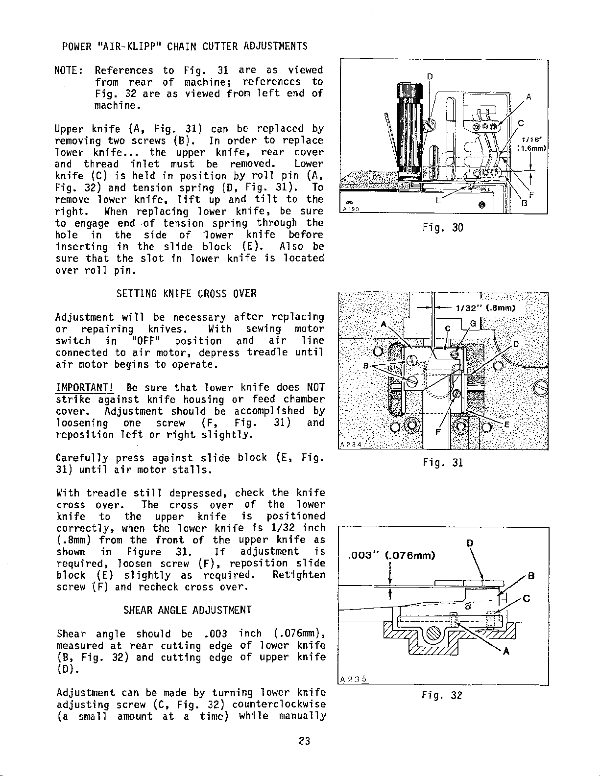
Needle
bar
eyelet
(A,
Fig.
conjunction with each other
TOP
and
BOTTOM
Adjustments
reposition
em/kg).
loosening
(A,
Fig.
Needle
29) and
top cover to underside
Thread Contra 1 Assembly
to both needle
light.
At
tension
loose
NOTE:
material.
Adjust
this
move
seam
Adjustment
point
of
can
eyelet
needle
and
Thread
with
stroke.
be
made
(A)
up
thread
thread
position
of
looper,thread
needle
a
longer
tight
Control
of
thread
needle
strike-off
or
cam
cam
adjustab
stitch
c
28) and
so
needle thread
by
bringing
down
as
required.
can be
mounting screw
strike-off
strike-off
1 e eye 1
and
tension
will
Assembly
loops.
wire
needle
needle
adjusted
(D)
wire
wire.
start
be
adjustable
et
to
pull
achieved.
can be
(B)
With
(C)
to
(For
Needle
with
strike-off
wire
bar
its
(C)
at
thread
just
contacts needle thread
bar
up.
TORQUE
forward
and
1/2
inch
needle bar
set
at
sew.
up
smallest
eyelet
raised
THREAD
Styles
HR,
bar
eyelet
eyelets
(B) on
as
shown
BOTTOM
of
cam
(B)
loosen
screw
screw (C)
or
rearward
retighten
screw.
(0.5mm) from top
at
11
"T
•
Looper
Without
to 11L".
to
CONTROL
BOTTOM
App
1 y
thread tension should
needle
changing
accormnodate
SETTINGS
XF512EIOOHB,
IOIHR
and
(A,
1/16
needle
in
Fig.
inch
Figure
stroke.
should
to
10
as
necessary
loop
This
will
MP,
XF513EIOOHJ
112HR)
30)
(1.6mm) below
thread
30,
be
set
cam
(B)
(C)
slightly,
in-lbs.
required
Loosen screw
(11.5
surface
of stroke
tension
as
required"
needle
thick
should
take-up
with
thread
produce a
dense
be
needle
in
at
by
of
and
be
set
cam
r -
Fig.
28
Adjustments
bar
up,
needle
reposition
needle
in-lbs.
Needle
set
needle
be
made
reposition
required
to
bar
bar
(11.5
thread
barely
bar
by
strike-off
threads
at
Assembly
at
strike-off
screw.
should
stitches.
thread
contact
BOTTOM
adjustable
"T".
Thread
be
should
can be
loosen
eyelet
down
up.
screw
(A)
TORQUE
em/kg).
take-up
contact
at
top
of
loosening
cam
and
(F)
of
Loosen screw
(B)
just
Thread
forward
retighten
should
strike-off
stroke
as
tension
enough
tension
be
just
made
to
by
(D)
BOTTOM
as
required
screw
cam
wire
needle
stroke.
cam
mounting
screw.
be
when
with
eyelet
(A)
specified
on
to
enough
bringing
slightly,
(C)
threads
Adjustment
or
rearward
set
needle
Thread
(C,
Fig.
and
and
needle
pull
app 1 i ed
to
steady
needle
of
stroke,
and
(D)
to
should
screw
Auxiliary
so
needle
bar
Control
29)
position
retighten
thread
up
uniform
on 1 ooper
thread.
bring
bring
10
be
with
can
(E).
as
is
set
22
Page 23
POWER
"AIR-KLIPP"
CHAIN
CUTTER
ADJUSTMENTS
NOTE:
References
from
Fig.
machine.
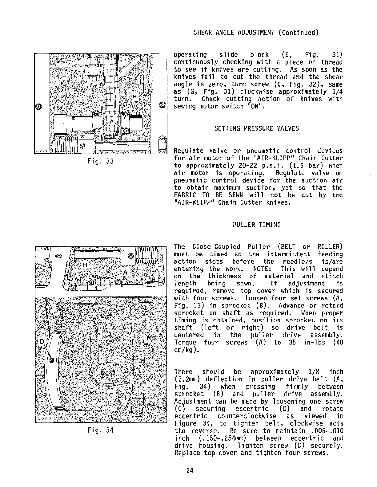
Upper
removing
1
ower
and
knife
Fig.
remove lower
right.
to
ho
inserting
sure
over
Adjustment
or
switch
knife
two
knife.
thread
(C)
32) and
When
engage end
1 e
in
that
roll
repairing
in 110FF
is
the
in
the
pin.
SETTING
connected to
air
motor begins
rear
32
are as
(A,
screws
. .
the
inlet
held
tension
knife,
replacing
of
side
the
s 1
will
knives.
air
to
of
Fig.
(B).
upper
must
in
lift
tension
slide
at
in 1 ower
KNIFE
be
necessary
11
pas
Fig.
machine;
viewed
31) can
position
spring
of
31
from
In
order
knife,
be
(D,
up
lower
spring
'1
ower
block
knife
CROSS
With sewing motor
it
ion
motor, depress
to
operate.
are
as
references
left
be
rep
to
rear
removed.
by
roll
Fig.
and
tilt
knife,
through
knife
(E).
is 1 ocated
OVER
after
and
treadle
viewed
end
1 aced by
replace
cover
Lower
pin
(A,
31).
to
the
be
sure
the
before
Also
replacing
air
1 i ne
until
to
of
To
be
Fig.
30
IMPORTANT!
strike
cover.
loosening
reposition
Carefully
31)
until
With
cross
treadle
over.
knife
correctly,
{
.Bmm)
shown
required,
block (E)
screw
Shear
{F)
angle
measured
(B,
Fig.
(D).
Be
against
Adjustment should
one screw
left
press
air
motor
still
to
the
-when
from
the
in
Figure 31.
loosen screw
slightly
and
recheck
SHEAR
should
at
rear
32) and
Adjustment can
adjusting
screw (C, Fig. 32)
(a small amount
sure
knife
or
against
The
upper
the
front
ANGLE
cutting
cutting
be
made
at
that
lower
housing
be
(F,
right
slightly.
slide
stalls.
depressed,
cross
over
knife
lower
of
knife
the
If
(F).
as
required.
cross
ADJUSTMENT
be
.003
edge
edge
by
turning
a time)
knife
or
does
feed chamber
accomplished
Fig. 31) and
block (E,
check
is
upper
the
of
the
positioned
is
1/32
knife
adjustment
reposition
Retighten
over.
inch
of
of
(.076mm),
lower
upper
lower
counterclockwise
while
manually
NOT
by
Fig.
knife
lower
inch
as
is
slide
knife
knife
knife
.003"
A?:35
Fig.
(.076mm)
t
Fig.
31
0
32
23
Page 24
SHEAR
ANGLE
ADJUSTMENT
(Continued)
Fig.
33
operating
continuously
to see
knives
angle
as
turn.
if
knives are
fail
is
zero,
(G,
Fig. 31) clockwise approximately 1/4
Check
slide
checking
to
cutting
block (E, Fig.
cutting.
cut
the
turn
screw
sewing motor switch 110W
SETTING
Regulate valve
for
air
motor
PRESSURE
on
pneumatic
of
the 11AIR-KLIPP
to approximately 20-22
air
motor
pneumatic
to
obtain
FABRIC
11
AIR-KLIPP
is
control
maximum
TO
BE
11
operating.
SEWN
Chain
device
suction,
will not
Cutter
PULLER
with a piece
As
thread
action
1
•
(C,
and
Fig.
of
VALVES
control
11
Chain
p.s.i.
for
(1.5
Regulate
the
yet
so
be
knives.
TIMING
of
soon
the
32),
knives
devices
bar)
valve
suction
that
cut
by
31)
thread
as the
shear
same
with
Cutter
when
on
air
the
the
Fig.
34
The
Close-Coupled
must
action
entering
on
length
required,
with
Fig.
sprocket
timing
shaft
centered
Torque
be
timed so the
stops
the
the
thickness
being
remove
four
33)
screws.
in
on
is
obtained,
(left
in
four screws
em/kg).
There
(3.2mm)
Fig.
sprocket
Adjustment
(C)
eccentric
Figure
the
inch { .150-.
drive
Replace
should
deflection
34)
(B) and
can be
securing
34,
reverse.
housing.
top
Puller
intermittent
before
work.
sewn.
top
sprocket
shaft
or
right)
the
the
NOTE:
of
material
cover
Loosen
(B). Advance
as
required.
position
puller
(A)
be
approximately
in
puller
when
counterclockwise
to
254mm)
cover
pressing
made
eccentric
tighten
Be
sure
Tighten
and
puller
by
belt,
to
between
screw (C)
tighten
(BELT
needle/s
This
If
adjustment
which
four
so
set
sprocket
drive
drive
to 35
drive
firmly
drive
loosening
(D)
as
clockwise
maintain
eccentric
four
or
ROLLER)
feeding
is/are
will
and
When
depend
stitch
is
secured
screws
or
retard
proper
on
belt
assembly.
in-lbs
l/8
belt
between
assembly.
one screw
and
viewed
.006-.010
secure
screws.
is
(A,
its
is
(40
inch
(A,
rotate
in
acts
and
1 y.
24
Page 25

The
feeding
by two
PULLER
motion
sprockets.
STITCH
of
combinations of nine
(59)
obtained.
28
combinations.
may
sewn.
appropriate
C50042-
To
Fig.
bracket
drive
removed
relaxed
removed.
make
end
direction
Reassemble
sprockets
handwheel
belt
be
C)
firmly
roller
tighten
different
that
Refer
list
puller
to
the
NOTE:
vary
When
z-(
slightly
ordering
dash number. Example:
) .
due
change sprockets loosen
35}
sure
of
does
necessary
slightly
and
to
release
belt.
for
position,
When
that
shaft
is
drive
(B
in
not
on
puller
is
setting
two
screws (A)
pas
it;
tension
NOTE:
clarity.
sprocket
installing
hub
of
and
operating
bind
to
1st
on
belt,
and
within
reposition
(left
assembly, making
evenly
LENGTH
the
puller
By
different
stitch
sprocket
various
Actual
to
sprockets
on
screws
Be
1t
With
(B
sprockets
sprocket
screw
the
C)
or
flat
tighten
securely.
direction
belt
right).
on
securely.
is
using
sprockets,
lengths
charts
stitch
material
two
screws
to
on
stitch
guard
drive
and
C)
is
flush
in
of
2nd
to
guard.
sprockets
Pull
sure
Idler
Roller
achieved
various
can
be
on
Page
sprocket
length
being
use
the
(A,
top
of
length
has
(B
operating
make
belt
can be
and
shaft.
screw
Rotate
It
(B and
been
in
C)
with
in
sure
may
down
puller
and
Fig.
35
The
roller
under hinged
inch
between
required
and
apply
clockwise
the
not
right).
Belt
evenly
XF511E152MF
"AIR-KLIPP
(3.2mm)
drive
loosen
turn
tension
tightens
reverse.
to
disturb
Tighten
Puller
on
11
eccentric
puller
belt
deflection
sprockets.
CAUTION!
(A, Fig. 37)
cloth
Belt
inlet.
belt.
guard
two
allen
on
belt
eccentric
two
plate
Puller
shaft
belt.
screws (A) securely.
which
(D)
should
when
If
screws
(B)
counterclockwise
Care must
shaft
must
(B).
will
is
have
pressing
adjustment
{A.
Fig.
slightly
Turning
be
(left
be
On
rest
located
setting
l/8
firmly
is
36}
to
shaft
acts
taken
or
Style
on
25
Fig.
Fig.
36
37
Page 26

PULLER
STITCH
LENGTH
(Continued)
Fig.
38
Belt
have
deflection
sprockets.
lock
nut
firmly
Puller
Roller
material
sewing
made
puller
approximately
drive
when
If
nut
(B) and
(B)
to
and
tighten
Roller
(A,
area.
by
shimming
Fig.
will
belt
pressing firmly between drive
adjustment
loosen
apply
nut
IDLER
must
39)
be
pulled
Adjustment
Idler
achieve even mating.
one screw (
assembly.
add
bearing
Puller
shims as necessary between
blocks
Roller
B,
Remove
to
and
Fig.
Idler
ensure
Idler
(A,
Fig.
l/8
inch
is
lock
tension.
(C)
securely.
ROLLER
be
set
evenly
to
ensure
straight
for
Roller
To
shim
39)
securing
Roller Assembly
even mating between
Roller.
38)
(3.2mm)
required
nut
(C).
Hold
nut
on
that
through the
feeding
if
necessary to
roller
plate
should
hold
Turn
(B)
Idler
the
can
be
remove
ro
11
er
and
and
Fig.
39
With
foot
puller
restin9
1/32 inch
(A,
Fig.
40)
adjustment
upper
and
Tighten
NOTE:
puller
presser
raise
connection
When
must
For sewing
action
raised
lock-up
collar
the
off
pin
(E).
clearance
be
can
raised
PULLER
in
on
(.Smm)
is
LIFT
operating
throat
between
and
puller
required
foot 1 ifting
or
lower
screw
presser
lift
at
operations
machine can
the
material
(D)
up
If
the
to
clear
or
lowered
ADJUSTMENT
position
plate
puller
lifting
loosen
link
(C)
foot
the
same
not
be
by
to
position
puller
material.
on
there
pin
screw
shaft
(A)
as
securely.
starts
time.
requiring
run
turning
has
stop
tension
and
presser
should
lifter
link
(B).
(C)
connection
required.
to
lift.
puller
with
the
puller
manual
under stop
insufficient
collar
shaft
be
If
in
(E)
(F)
Fig.
40
26
Page 27

PULLER
to
suit.
so
it
exerts
to
feed work. Turning
increase the
the
straight
main
lay
reverse.
stitch
flat,
LIFT
Adjust
only
presser,
through behind
length
until
ADJUSTMENT
puller
enough
tension
pressure
regulator
counterclockwise
If
material
presser
slightly
material
is
(Continued)
regulator
on
clockwise
does
so
not
foot
material
straight.
(G)
puller
to
acts
pull
adjust
will
Stitch
factory
recommended
adjustment
Fig.
for
gives
The
to
rocker
activates
the
operation.
shortening
41)
less
more
connecting
the
collar
shaft
desired
STITCH
to
and
stitch
is
required
turn
produce
stitches
stitches
arm
adaptor (B)
(C).
the
feed
stitch
SHORTENING
device
length
DEVICE
is
one-half
loosen
stop screw
per
inch~
per inch.
(A,
Fig.
located
The
connecting
rocker
1
ength
shaft
set
per
lock
(B)
at
of
inch.
screw (A,
clockwise
the
the
counterclockwise
42)
is
connected
on
the feed
arm
to
depending
(A)
achieve
If
on
Fig.
41
Fig.
40
27
Page 28

PULLER
SPROCKETS
COMBINATIONS
This
chart
shows
the
stitch
Sprockets furnished in the
different
length
is
required~
ordering sprockets-C50042-Z-(
13.10
SPI
11.92
SPI
(2.13mm)
11.26
SPI
(2.26rnm)
10.60
SPI
{2.40mm)
9.!J4
SPI
(2.56mm)
~
~
~
~
~
z
~
~
~
~
~
~
u
0
~
~
~
z
~
~
~
0
--HI
--
17
--16
-15
-14
-13
--12
11
(1.94mrn)
12.37
SPI
(2.05mm)
11.65 SPI
(2.18mm)
-
1--
length produced
machines
refer
produces approximately 9.2
to
the chart
by
).
Belt Puller Sprocket Variations
NUMHF.R
10.92
(2.33mm)
10.31
{2.46nuu)
9.71 SPI 8.96 SPI 8.33 SPI
{2.62mm)
9.10
(2.79rnm)
8.49
(2.99mm)
OF STITCHES PER I;\'CH
SPI
10.08
SPI
(2.:i2mm)
SPI
9.52 SP! 8.84 SPI 8.25 SPI
(2.67mm)
(2.83mm) (3.05mm) (3.27mm)
SPI
8.40
{3.02mm)
SPI
7.84SPI
{3.24mm)
7.28
(3.49mm)
9.37 SPI"
{2.71mm)
(2.87mm}
SPI
7.81
SPl
{3.25mrn)
7.28
SPI
{3.49mm) {3.74rnm)
SPI
6.77
SPI
(3.75
mm)
6.24
SPI
(4.07mm)
~~-74
(2.!J1mm)
{3.08rnm)
7.77
7.~11
(3.49rnm)
6.79
6.31
(4.02rnm)
5.83
(4.30mm)
5.34
(4.7fimm) (5.0/lrrnn)
available
for
appropriate dash
SPI 8.19
(3.10mra)
7.73 SPI'
(3.28mm] (3.49mm)
SPI
7.28
l(3.49mm)
SPI'
1~-83
1
{3.72mm)
SPI'
1~-37
1
(3.99mrn) (4.24rnm) (4.49mrn)
SPI'
1~-92
1
(4.29mm) (4.56mm)
SPI,J~-46
(4.65mrn)
SP!d
I
~.00
sprocket combinations.
sr;,ll;-71
(3.29mm)
1:-28
1
SP1'
1~-86
1
(3.70mm)
6.43
SPI
{3.95mm)
5.oo
SPI
5.57
SPI
5.14
SPI
(4.94rnrn)
4.71 SPJ
SPI
(5.39rnm)
SPI
SPI
SPI
SPJ
Sl'!
SPJ
SPI
S.P.I.
number
6.88 SPI
{3.69mm)
6.411
SP!
{3.92mm)
6.07
Sl'l
(4.19mm)
5.1iG
Sl'l
s.2n
SPI
(4.83mm)
4.1l6
Sl'l
(5.23mrn)
4.45
SPI
(5.71mm)
If
when
a
-10
-1
17
"
15
"
t:l
"
"
10
14.69
8
(1.73mrn)
13.87
{1.83rmn)
13.06
(194mm)
f---~
f--
I
----
-10
-
SPI
SPI
SPI
10
-11
13.37
Sl'l
(l.!Hlmm)
12.!;2 SPJ
(2.01mm)
~
11.811
Sl'l
(2.13mm)
~~
11.14
SPI
(2.28mrn)
-11
-12 -13
DRIVE SPROCKET PART NUMBER
-····
RoJIP.r
Puller Sprocket Variations
NUMBER
12.25
{2.07mm)
11.56
(2.20mm)
10.89
(2.5~mm)
10.21
{2.4!lmm)
9.52
[2.67mm)
11.30
SPI
[2.25mm)
---~-----
10.fi7 SPJ 9.91
SPI
(2.38mm)
10.05
Sl'J
(2.53mrn}
SPI
\!.42 SPI
(2.70mm)
SPI
!:1.76
(2.89rnm)
-
!:1.16
(3.11mrn)
OF
~~
-14
STITCHES
S!'l
10.50
(2.42rnm)
(2.5fimm)
SPI
9.31
(2.72mm)
8.75
(2.!lllmm)
8.16
SPI
[:-1.11mm)
7.59
SPI
(:L-15mm
7.00
[:-1.63rnm)
PER 1:\CH
9.80
SPI
SPI
SPI
SPI
Sl'l
SPI
) (3.59rnm)
SPJ 6.53 SPI
----
I
-
-12
URIVF.
-13
SPROCKET PART NUMBER
~~
"
28
1;-ss
(5.58mm) (5.92mm)
-15
....
SP! !1.18
[~.59mm)
S.25
(2.75mm)
~·
8.71
(2.92mm)
-
8.W
(3.11mm)
7.62 SPI
(3.33mm)
7.08
(3.8\hmn)
5.98
(4.24mm)
(2.77mrn)
Sl'l
8.67
(2.93mm)
SPI
8.16
(3.11mm) (3.30mm)
SPI
7.65
(3.32mm)
7.11
[3.0Jfimm)
6.63
SPI
(:J.H:-Jmm)
612
(4.15mm)
5.fi1
SPI
(4.53mm)
~-
5.10
(4.98mrn)
-15
SPI
-1G
SPI
SPI
-16
SPI
SPI
Sl'I
SPI
Sl'l
SPI
SPI
1.29
SPI
-17
8.65
SPI
(2.!l4mm)
8.16
Sl'l
[:-1.11mm)
~--
7.fi!l
Sl'!
~
7.21
Sl'l
(3.52mm)
fi.72
Sl'l
(3.78mm)
fi.25 SPI
(4.07rnrn)
5.76
SPI
(4.11rnm)
5.28 SPI
(4.81mm)
4.131
SPJ
(01.2Hmm)
-17
4.05
(fi.27mm]
-10
~-~-
7.71
(3.30mm)
---
7.26
{3.50mm)
6.80
(3.73rnrn)
6.35
(4.00rnm)
5.90
(4.31mm)
5.44
(4.ti7mm)
4.99
(5.09mm)
4.014
(5.60mm)
~--
SPI
Sl'l
SPI
SPI
SPI
SPI
Sl'l
Sl'l
---~---
SPI
_,
Page 29

EXPLODED VIEWS
AND
DESCRIPTION OF PARTS
29
Page 30

'"
16-18
in.
lbs.
D.B-?l_c~
I 1
f><
30
Page 31

LUBRICATION
PARTS
Ref. Part
No. No.
1
2
3
4
5
6
C50093
C50093
C50093
C50093
56322
671
7 79-31
8
9
10
11
12
13
14
15
16
17
18
19
20
21
22
23
24
25
26
27
28
29
30
31
32
33
34
35
36
37
38
39
40
41
42
43
44
45
46
47
48
49
50
51
52
and
C50093
22730
50393
50393
671
50393
666-322
50393
50393
50393
50393
660-220
22652
660-885
C50094
660-683
73
C50094
C50094
C50094
C50094
22720
C50094
C50094
C50094
RI-37
C50093
C50094
22720
C50094
C50094
RM3728-l
C50094
C50093
660-750
660-749
C50094
C50093
660-855
671
C50094
666-294
670
671
53
CG
CH
CJ
CL
B
F-4
CM
AX
DC
F-41
AY
cu
cs
CY
v
B-12
P
G
AM
F
V
B
U
C
Y
BX
AA
A
Z
8
R
BE
AC
CV
C-4
E-2
F-41
Description
Oil
Syphon
Tube,
Tube,
Fitting,
Gasket
Fitting,
Ball,
Manifold,
Screw
Tube,
Oil Return
Tee,
Tube,
Felt
Tube,
Spring, tube retainer
Tube,
Retainer, wire
"011
Ring
Screw
Clamp,
Tube,
••o••
Ring
Screw
Screen,
Screen,
Strainer,
Tube,
Screw,
Connection,
Connection,
Tube,
Ring, wire
Valve, check
Tube,
Screw,
Tube,
Connection,
Fitting,
Tube,
Nut
------------------------------------------------
Sleeve, compression
Nut, compression
Tube,
Valve,
Connector, compression
Connector,
Tube,
Elbow,
Tie,
Tee,
See
cable; to secure Ref.
unioP
Following
Assembly--------------------------------
syphon
oil
----------------------------------------
steel
-----------------------------------------
oil
return
Tube
union
sleeve
drain
return
barb
barb
-----------------------------------
oil
-----------------------------------
Assembly
------------------------------------
----------------------------------
----------------------------
------------------------------
---------------------------------
---------------------------------
syphon
--------------------------
---------------------------
------------------------------------------
oil
return
oil
return
(oil
-------------------------------------------
------~---------------------------------------
oil
tube
------------------------------------
oil
------------------------------------------
-------------------------------------------
----------------------------------------------
oil
filter
oil
----------------------------------------
oil
--------------------------------------
oil
------------------------------------------
oil
connection
oil,
oil,
oil
------------------------------------------
-----------------------------------------
---------------------------------------
oil
------------------------------------------
oil
connection
oil
------------------------------------------
oil,
oil
---------------------------------------
oil
------------------------------------------
oil
------------------------------------------
priority
oil
------------------------------------------
male
------------------------------------
male
----------------------------------------
-----------------------------------------
Page
------------------------------
-------------------------
------------------------------
tube)
---------------------------------
single
single
double
--------------------------------
-----------------------------------
--------------------------
------------------------------
feed----------------------feed-----------------------
------------------------------
feed-----------------------
------------------------
-------------------------------
No.
2 to Ref.
No.
48
----
Amt.
~
I
1
1
1
2
1
1
1
1
1
1
1
1
1
1
1
1
1
5
4
1
4
5
2
1
1
1
1
2
2
7
1
6
1
1
8
1
1
1
1
2
2
2
1
1
1
1
1
2
I
1
31
Page 32

J
r'
!-
'
L
L_
~···
'lliiQUE
80
in.
11?
__
,,.,&)
l 0
lbs
30
-
_j
TORI,llJE
TO
80 ; .. _ lb.<
(92_cm/kq)_-
p 1 6 i
32
Page 33

OIL
PAN
AND
LUBRICATION
PARTS
Ref.
No.
1
2
3
4
5
6
7
8
9
10
11
12
13
14
15
16
17
18
19
20
21
22
23
24
25
26
27
28
29
30
31
32
33
34
35
36
37
38
39
40
Part
No.
C50093
22652
C50093
C50093
C50093
660-684
C50093
C50093
C50093
22784
C50093
C50093
660-739
C50093
22764
C50093
C50093
660-206
22541
C50093
C50093
22541
56322
22851
C50093
22592
C50093
C50094
666-294
C50093
C50093
C50093
C50093
C50093
22569
C50093
22571
C50095
C50093
22881
L
A-20
M
U
T
S
R
P
E
Z
N
BS
CB
CA
F
G
c
B
A
B
AN
W
AJ
BH
AA
AE
AG
c
AH
E
AB
B
Description
Oil
Pump
Assembly
Screw
Housing,
-----------------------------------------
----------------------------------
pump
(pressure)
Gerotor, 1/4 inch
Divider,
••o•'
Spacer, housing
housing
Ring
--------------------------------------
Gerotor, 1/8 inch
Shaft
Pin,
Housing,
Seal,
Coupling
By-Pass,
Filter,
••o••
Ring
Screw
Cover
Gasket
Screw
Gasket
Screw
Manifold, flow control
Screw,
and
ISIMF
Cooler,
112MG
By-Pass, tube,
XF511HIOOMF,
Elbow,
Fitting,
Gasket
Pan.
oil
Sleeve. stand pipe
Plate,
Screw
Screen,
Screw,
Screw
Gasket
Screw
-----------------------------------------
Screw
dowel
------------------------------------
------------------------------------
pump
(suction)
lip-------------------------------------
--------------------------------------
Screw, spot
oil
filter
oil
----------------------------------------
--------------------------------
-------------------------------------------
----------------------------------------------
----------------------------------------------
---------------------------------------------
----------------------------------------------
---------------------------------------------
----------------------------------------------
for
Styles
XF511HIOOMF,
-----------------------------------------
oil;
and
male
for
Styles
151MF
-----------------------------------
oil
cooler;
MG,
MAW,
----------------------------------------
adaptor
-----------------------------------
---------------------------------------------
-------------------------------------------
filter
-----------------------------------------
filter
oil
----------------------------------------------
---------------------------------
--------------------------------
drain plug (magnetic)
---------------------------------------------
----------------------------------------------
----------------------
(6.4mm)
thick
---------------
------------------------------
-------------------------------
(3.2mm)
thick
---------------
-----------------------
------------------------------
-----------------------------
XF511HIOOMF,
112MF,
----------------------------
all
MG,
MAW,
Styles
112MG
112MF,
MG,
MAW,
except
and
151MF
--------------
112MG
112MF,
------
Amt.
~
1
4
1
1
1
1
1
I
I
I
I
I
I
I
I
I
1
1
4
I
1
1
1
I
I
2
I
I
2
2
2
1
1
1
12
1
2
8
I
2
33
Page 34

I
--+-
---24
'
---
--
PIH2
34
Page 35

~~IN
FRAME
BUSHINGS
AND
PlUGS
Ref.
No.
1
2
3
4
5
6
7
8
9
10
11
12
13
14
15
16
17
18
19
20
21
22
23
24
25
26
27
28
29
30
31
32
33
34
35
36
37
38
39
40
41
42
43
44
45
46
47
48
49
50
51
52
Part
No.
C50093
22894
C50090 K
C50055 S
C50055
C50054 D
22539
50354 D
C50090 E
C50055 K
C50093
22839
22587 N
C50080 B
C50093
C50093
C50057 D
C50090 F
C50090 G
C50082 D
C50082 E
C50036 J
C50035 Z
C50051 X
C50049 A
C50036 U
C50035 Y
C50044 F
C50068
C50068 X
C50044 0
C50044 G
C50035 G
C50093
C50082
C067 H
666-311
87
22570
660-739
661-1
50354
51-627
666-32
50393
50393
22733
50393
50393
50393
22569
22521
C067 F
AY
K
l
G
CT
AW
AX
E
OD
ex
cs
cv
cz
G
AG
DB
DA
BlK
Description
Plug,
Screw
Bushing.
Bushing, upper mainshaft
Bushing, upper mainshaft
Plug, cork
Shield,
Screen, needle bar bushing
Screw, plug
Bushing, needle bar (upper)
Bushing,
Bushing, upper mainshaft
Plug,
Screw
Screw
Ferrule,
Screw,
Screw,
Seal,
"0"
Plug,
Plug,
Bushing, needle bar (lower)
Bushing,
Bushing,
Bushing,
oil
---------------------------------------------------
------------------------------------------------------presser
foot
lifter
(right)
(center)
lever
(right)
----------------------------
---------------------------
--------------------------------------------------
needle bar bushing
----------------------------------
----------------------------------
-------------------------------------------------
---------------------------------
presser
oil
---------------------------------------------------
foot
lifter
(left)
lever
(left)-------------------
-----------------------------
-------------------------------------------------------
------------------------------------------------------locating
all
Styles
XF513EIOOHJ-8,
for
Styles
HJ-9,
HR-9,
oil,
presser
Ring, needle bar bushing (lower)
oil
---------------------------------------------------
oil
---------------------------------------------------
------------------------------------------except
HJ-9,
XF512ElOOHB-1,
101HR-9
bar
XF512E100HB-l,
HR-9,
101HR-9
and
MP-12, MP-16,
and
112HR-9
----------------------------
bushing------------------------------
------------------------
--------------------------------presser
presser
presser
bar
----------------------------------------
foot
foot
lifter
lifter
lever
lever
(rear)-------------------
(front)
------------------
MP-12,
MP-16,
112HR-9
XF513E100HJ-8,
------------------
Plug-------------------------------------------------------Felt,
Needle
Cover, feed chamber;
Screw
Gasket
Bushing, feed rocker
Plug
Plug,
Window,
Screw,
Bushing, feed rocker
Bushing
Bushing, feed
Bushing,
Bushing,
Bushing, looper rocker
Bushing, feed
Bushing,
Plug, cork
Plug,
Cover, feed chamber;
oil
return
Bar
Oil
Plate,
Screw
Spring, tube
Tube,
oil
Spring
XF5IIEI52MF, XF513EIOIHR-9, XF513EII2HR-9,
XF511H112MF,
--------------------------------------------
Collector
oil
collector-----------------------------------
Plate
Assembly
---------------------
--------------------------------------------retainer
return
----------------------------------
---------------------------------------
------------------------------------------------all
I12MG
and
Styles
151MF
except
XF511E101MF,
------------------------------
-------------------------------------------------------
-----------------------------------------------------shaft
(right)
--------------------------
-------------------------------------------------------stitch
adjustment hole
stitch
indicator
--------------------------------
(left)
-----------------------------
plug-------------------------------------------------
shaft
(left)
---------------------------
-----------------------------------------------------
(left)
drive
rear
needle guard
rear
needle guard
drive
-----------------------------------------------------
stitch
shaft
shaft
control
(left)
shaft
(right)
shaft
---------M------------------ 1
shaft
shaft
(left)
(right)
---------------------
--------------------
-------------------------------and
lower mainshaft
-------------------------------
--------------------------------------------------
oil
---------------------------------------------------
XF513EIDIHR-9
----------------------------------------------
for
Styles
XF511El01MF
and
-------------
Amt.
~
3
1
I
1
1
1
1
1
1
1
1
1
1
3
2
2
2
2
1
1
1
I
I
1
I
1
I
1
1
1
1
2
I
I
I
10
1
1
2
1
1
1
1
1
1
1
1
2
I
I
I
1
35
Page 36

13- -
14
16---
--,.,
-------5
---4
45-
-44
p I
bCJ
36
_
__j
51
--53
Page 37

SAFETY
SHEILD,
CpVERS
AND
CLOTH
PLATES
Ref.
No.
I
2
3
4
5
6
7
8
9
10
11
12
13
14
15
16
17
18
19
20
21
22
23
24
25
26
27
28
29
30
31
32
33
34
35
36
37
38
39
40
41
42
43
44
45
46
47
48
49
50
51
52
53
Part
No.
22851
D
C50082
C50082
21192
C50093
C50093
C50082
C50082
C50082
22597
22861
C50082
C50082
22569
C50082
C50082
C50082
22541
50382
C50082
22883
L
T
R
AS
AU
X
U
UA
E
c
N
M
M
V
K
AW
c
8N
AA
B
660-219 A
C50095
C50095
C50095
G
D
E
97127
12934
A
RM2879-2
C50095
C50001
F
A
C50049
22569
G
87
C50032
C50032
C50001
C50001
C50001
C50001
C50001
22585
22569
22569
D
B
u
B
B
B
C
E
G
J
22517
C50082
C50082
C50082
C50082
22526
22569
99679
99679
50382
B
C
AK
AJ
H
G
sc
so
BP
660-739
660-896
22569
22569
w
C50090
C5007
22569
A
c
5
Amt.
Description
Screw
Cover,
Gasket
Cap,
Gasket
Cover, top
Cover, top
Cover,
Cover,
v
--------------------------------------------------------------oil
cooler
---------------------------------------------------
--------------------------------------------------------------
Ball,
Indicator,
steel
oil
---------------------------------------------------------
oil
flow
-------------------------------------------------
filler
-----------------------------------------------------
--------------------------------------------------------------
for
single
for
two
Screw
Screw
Gasket
Screw
Gasket
Gasket
Screw
Cover, head;
Gasket
----------------------------------------------------
---------------------------------------------------------------
-------------------------------------------------------------head
(right
--------------------------------------------------------------head
{left
--------------------------------------------------------------
--------------------------------------------------------------
---------------------------------------------------------------
all
--------------------------------------------------------Screw, plug
Pin,
roll
------------------------------------------------------
Safety Shield Assembly
Stud
----------------------------------------------------------Bracket, mounting
Washer, spring
Nut
-----------------------------------------------------------Rivet
Shield,
Plate,
Window,
Screw
Screw
Plate,
Spring,
Screw,
Screw,
and
Screw,
Plate,
MAW
Plate,
---------------------------------------------------------mounting
cloth
{right)
stitch
---------------------------------------------------------------
--------------------------------------------------------------nut
----------------------------------------------------------
latch
for
for
C50001
for
cloth
{front
cloth
cloth
J
------------------------------------------------------
cloth
{left)
---------------------------------------------------------------
cloth
{left)
XF513E100HJ-8,
Plate,
Plate,
Plate,
Screw
Cover, end
Gasket
Gasket
Cover, end
Screw
Screw
Plate,
Plate,
Cover,
Sc
Screw
Cover,
Screw
Cover, blower
cloth
cloth
cloth
{left)
{left)
{left)
---------------------------------------------------------------
----------------------------------------------------------
--------------------------------------------------------------
-------------------------------------------------------------{front)
---------------------------------------------------------------
--------------------------------------------------------------cloth
cloth
151MF
-------------------------------------------------------------head
Seal,
Bushing
re~1
---------------------------------------------------------------
{left)
(left)
(puller
lip------------------------------------------------------
--------------------------------------------------------
--------------------------------------------------------------pulley
assembly----------------------------------------------
---------------------------------------------------------------
-------------------------------------------------------
needle machines
and
three
rear)
all
rear)
Styles
all
except
needle machines
Styles
Styles
puller
-------------------------------
except
except
puller
puller
machines----------------------
----------------------------------------------------
----------------------------------------------
----------------------------------------------
-------------------------------------------------
-----------------------------------------------
------------------------------------------------
plates
plate;
plate;
HJ-9
indicator
cover)
--------------------------------------------Nos,
Nos.
for
Styles
for
Styles
and
for
Style
for
Style
for
Style
---------------------------------------
----------------------------------------C50001
99679
B,
SO
CSOOOl
and
99679
XFSllBlOOMF,
XF512E100HB-1.
HR-9
--------------------------------------XF511E101MF
XF511Ell8MF
---------------------------
---------------------------
XF513E101HR-9
--------------------------------------------------
for
Style
for
Styles
machines)
XF513E112HR-9
XF511E152MF,
---------------------------------------
------------------------
machines
machines
C,
C50001
SC
------------------
XF511H100MF,
MP-12,
----------
-----------
E,
C50001
MG
and
~1P-16,
-------------------------
------------------------XF511Hl12MF,
112MG
and
1,
G
2
~
4
I
I
I
I
I
I
I
I
oc 3
4
I
I
9
I
I
I
4
I
I
I
I
I
I
I
2
2
2
I
I
I
5
2
I
I
I
4
2
I
I
I
I
I
8
1
I
I
I
2
2
I
I
I
I
I
2
2
1
5
1
37
Page 38

TORQUE
TO
28
in.
l~s.
(32 CI?/kg)
)
51
38
55
61
Page 39

R!!f.
.11.9.·,
1
2
3
Part
No.
C~0055
22653
660-721
660-721 c
4 22720 A
5 C50094 X
5 41350 X
7
8
9
10
11
12
13
14
15
15
17
18
19
20
21
22
23
24
25
25
27
28
29
30
31
32
33 21237
34
35
35
37
38
39
40
41
42
43
44
45
45
47
48 C50022 J
4.9
50
51
52
53
54
56
"'
57
18
;g
60
51
RM3633-l
671
50393
660-220
C50055 C
C50055 W
C50055
660-206
22806 D
22597 E
C50094
29480
41071 G
671 F-73
671
RM2964
53193 B
671 F-71
671 C-4
660-762
C50067 L
22894 R
660-400
660-989
21237
21237
21237
21237
21237
660-886
51-673
22784 N
RM2964
RM3633-1
660-93
671-17
671 F-4
RM2964
22882 D
C50043
22652 A-8
22894
C50042 M
22894
C50042 Y
660-713
C50036 P
22894
C50093
660-708
660-680
C50093
C5002l A
C5002l E
22894 c
22894 E
~6322
22730
22569
J-4
F-4
CF
Y
AJ
XA
F-4
B
DG
DP
DF
EA
DR
Dll
B
B
AE
AE
AD
AK
BK
B
lJ
Description
Connection,
Screw
Bearing,
A
Bearing,
Screw
Fitting,
Washer,
Fitting,
Fitting,
Tube,
"0"
Ring
Eccentric,
Cardan
HJ-9,
Cardan
IOIHR-9 and ll2HR-9
"0" Ring
Screw
Screw
-------------------------------------------------------------------------------
Tube
Vacuum
Nut,
Valve,
Spring
Tube Assembly
Connector,
~~~s~~~:
Screw
Fitting,
Clamp,
N~edle
ll2HR-9
Needle
Tube,
Tube,
Tube,
BLK
Screw
Coupling,
Screw
Screw,
Sprocket,
Screw
Be
1
t,
Mainshaft,
Ring,
Bearing
Screw
Housing,
Seal,
Handwheel,
JOIHR-9 and
Handwheel,
and 112HR-9
Screw
Gasket
Screw
Screw
needle
bar
-------------------------------------------------------------------------
cage
(counterweight
cage
(counterweight
-----------------------------------------------------------------------------air
-----------------------------------------------------------------------
fiber
---------------------------------------------------------------------swivel
barb
air
------------------------------------------------------------------------------
---~--------------------------------------------------------------------------
Fi
------------------------------------------------------------------------------
"0" Ring
Kolder,
101HR-9 and 112HR-9
Holder,
ll2HR-9
------------------------------------------------------------------------------
upper
retaining
"0" Ring
Shield,
Screw,
------------------------------------------------------------------------------
------------------------------------------------------------------------------
------------------------------------------------------------------------------
----------------------------------------------------------------------
--------------------------------------------------------------------------
---------------------------------------------------------------------------
far
Drive
HR-9, lOlHR-9 and 112HR-9
Drive
Assembly
tti
-----------------------------------------------------------------------------
internal
Assembly,
Assembly,
---------------------------------------------------------------------------
lock
---------------------------------------------------------------------
needle-----------------------------------------------------------------
og,
barb
Gasket
----------------------------------------------------------------------
male
~i~-=======================================================================
straight------------------------------------------------------------------
tube
------------------------------------------------------------------------
Cooler,
Cooler,
-----------------------------------------------------------------------------
for
--------------------------------------------------------------------------for
needle
needle
needle
----------------------------------------------------------------------
needle
needle
---------------------------------------------------------------------Screw
Gasket
Fitting,
Washer
Valve,
Fitting,
Gasket
upper
------------------------------------------------------------------------set
upper
------------------------------------------------------------------------rna i nshaft
upper
and
Collar
-------------------------------------------------------------------------
rna
insha
----------------------------------------------------------------------
oil
---------------------------------------------------------------------
oil
for
all
ll2HR-9
for
Styles
-----------------------------------------------------------------------
set
------------------------------------------------------------marked "A")
marked "C")
--------------------------------------------------------------------
tooth
gear-------------------------------------------------
for
all
far
Styles
---------------------------------------------------------------
--------------------------------------------------------------------
-----------------------------------------------------------------
-------------------------------------------------------------------
--------------------------------------------------------------------
all
Styles
Styles
cooler
cooler
cooler
--------------------------------------------------------------------
-------------------------------------------------------------------
------------------------------------------------------------------control
mainshaft
-------------------------------------------------------------------mainshaft
-------------------------------------------------------------------
--------------------------------------------------------------------
ft
seal
--------------------------------------------------------------------
XF!>l3El00HJ-8,
for
single
for
two
for
three
cooler;
cooler;
swivel
barbed
Assembly-------------------------------------------------------oi 1 sea 1 --------------------------------------------------------
Styles
all
---------------------------------------------------------for
----------------------------------------------------------
-----------------------------------------------------------
----------------------------------------------------------
--------------------------------------------------------------
----------------------------------------------------------
----------------------------------------------------------
timing
-------------------------------------------------------
housing------------------------------------------------------
except
--------------------------------------------------------------XF512ElOOHB-l, XF513ElOOHJ-8,
-------------------------------------------
-------------------------------------------
Styles
except
--------------------------------------------------XF512El00HB-1, XF513El00HJ-8,
except
XF513ElOOHJ-8,
needle
needle
needle
Styles
Styles
XF512ElOOHB-l, XF513EIOOHJ-8,
XF5ll'E100HB-l. XF513El00HJ-8,
HJ-9,
HR-9, 101HR-9 and
HJ-9,
HR-9, lOlHR-9 and 112HR-9
machines
machines
machines
except
XF513E100HJ-8,
--------------------------------
-----------------------------------
---------------------------------
XF513EIOOHJ-8,
HJ-9,
HR-9, 101HR-9 and
HJ-9,
HR-9, 10HIR-9
HJ-9,
HJ-9,
HJ-9,
HR-9,
HR-9,
HR-9,
-----------
Amt.
~
l
1
1
1
1
1
1
1
1
1
1
1
1
l
2
1
1
I
1
1
1
1
l
I
1
i
1
1
1
1
1
1
1
1
1
l
1
1
1
1
1
l
1
1
2
1
2
2
1
4
1
1
1
1
2
1
1
1
I
1
I
2
1
1
1
2
39
Page 40

15
TORQUE
28
ill___!:~
fn.
TO
lbs.
19
49
1'166
40
Page 41

LOWER
~JNSHIIFT
AND
LOOPER
j)_R]_I!l
Ref.
No.
1
2
3
Part
No.
141
HA20
C50021
C50021
4
5
6 660-688
7
8
9
10
11
12
13
14
15
16
17
18
19
20
21
22
23
24
25
26
27
28
29
30
31
32
33
34
35
36
37
38
39
40
41
42
43
44
45
46
47
48
49
50
51
52
53
54
55
56
57
58
59
60
61
62
63
64
65
66
67
22651
C50021
C50090
22569
C50090
660-757
C50036
22894
22894
C50090
22520
C50022
C50042
22839
660-719
C50042
98
C50042
C50043
22894
22652
22731
C50093
C50023
22580
C50023
C50023
C50077
22797
C50042
88
C50057
22729
22528
9846
C50057
22569
C50014
C500I4
660-207
660-443
29105
22653
667
29192
660-445
C50044
22569
C50044
C50057
22768
87
52904
50-216
52804
C50004
73
2<"516
52958
C50057
303
53634
50358
A
D
F
CD-4
C
B
B
P
AD
L
D
A
H
A
G
AD
AE
A-8
BC
F
D
E
G
P
B
F
A
B
A
C
G
A
AP
J-8
J-33
AE
A
G
V
B
u
E
E
A
D
c
H
Description
Screw
--------------------------------------------------------------------
Washer
Pulley,
Pulley,
Spacer,
Seal,
Collar,
Screw
Housing, mainshaft bearing
"0"
Bearing
Screw, spot (requit·ed
Plate,
Screw
Ma
Sprocket, lower mainshaft
Seal,
Sprocket, looper drive
Belt,
Coupling, lower mainshaft
Screw
Shaft,
Take-Up
Sprocket, looper driven
Bracket,
Screw
Screw
Block,-
Screw
Plate,
Eccentric,
"0"
"0"
Looper Drive
Rocker Assembly, looper
"0"
Housing, looper rocker bearing
------------------------------------------------------------------for
and
Styles
for
all
Screw,
151MF
set
pulley;
---------------------------------------------------------------
mainshaft
spacer
XF511HlOOMF,
Styles
---------------------------------------------------------for
all
except
Styles
MG,
MAW,
112MF,
XF511Hl00MF,
except
XF511H100MF,
MG,
112t~G
HAW,
----------------------------------------------------------
----------------------------------------------~------------
--------------------------------------------------------------------
-----------------------------------------------
Ring
-----------------------------------------------------------------
and
Screw,
inshaft, 1 Ol'.'er
set
----------------------------------------------------------
-retaining
--------------------------------------------------------------------
---------------------------------------------------------
---------------------------------------------------------
Collar Assembly
----------------------------------------------
to
replace screw in Ref.
No.
------------------------------------------------
Screw
---------------------------------------------------------------
oil
----------------------------------------------------------------
Screw,
set
----------------------------------------------------------
looper drive
----------------------------------------------~----
-------------------------------------------------------
-----------------------------------------------Screw,
Screw
set
----------------------------------------------------------
---------------------------------------------------------------
-------------------------------------------------------------------connecting
Assembly, looper thread
Screw,
Coupling
Disc, take-up
Spacer
Screw
---------------------------------------------------------------
--------------------------------------------------------
------------------------------------------
set
----------------------------------------------------------
------------------------------------------------------------
-------------------------------------------------------
--------------------------------------------------------------
--------------------------------------------------
Screw,
Screw
set----------------------------------------------------------
collar
----------------------------------------------------------
---------------------------------------------------------------
--------------------------------------------------------------------
--------------------------------------------------------------------
·pivot
-------------------------------------------------------------
-------------------------------------------------------------------eccentric
Ring
-----------------------------------------------------------------
Ring
-----------------------------------------------------------------
Screw
Crankpin
retaining
looper avoid
Assembly
-----------------------------------------------
adjusting
----------------------------------------
---------------------------------------------------
---------------------------------------------------------------
------------------------------------------------------------
--------------------------------------------------
Ring
-----------------------------------------------------------------
------------------------------------------Screw-------------------------------------------------------------------Sea
1 , oi 1
Cast-Off Support
BLK
Screw
Washer
Eyelet
---------------------------------------------------------------Plate
Assembly------------------------------------------
Screw
---------------------------------------------------------------
Screw
---------------------------------------------------------------
Bracket,
Support,
1-Ji
re,
Screw
Screw
Eyelet
Support,
retaining
Pin,
dowel
retaining
cast-off
---------------------------------------------------------------
---------------------------------------------------------------
finger
support
-----------------------------------
----------------------------------------------------finger-------------------------------------------
---------------------------
-
--------------------------
-------------------------------------------------------------cast-off
plate
---------------------------------------------
--------------------------------------------------------------------
------------------------------------------------------------------(t.wo
and
three
needle machines)
-----------------------------------
and
151MF
112MF,
MG,
11)
ll2MG
MAW,
112MF,
-------------------
---------and
151MF
112MG
Amt.
~
1
1
1
1
2
1
1
1
3
1
1
1
1
1
1
3
1
1
2
2
1
2
1
1
2
2
2
1
1
2
1
2
1
2
1
2
1
1
1
1
1
2
1
1
1
1
1
1
1
1
1
1
3
1
1
1
1
1
1
1
1
3
1
2
1
1
1
2
41
Page 42

TORQUE
TO
24-26
fn.
Tbs.
{28-30 em/kg)
65
'm,aur
24-26
128-30
ro
in.
Tbs
cm(kg) •
56
57
Pt68
42
Page 43

FEED
DRIVING
PARTS
Ref.
No. No.
1
2
3
4
5
6
7
8
9
10
11
12
13
14
15
16
17
18
19
20
21
22
23
24
25
26
27 96A
28
29
30
31
32
33
34
35
36
37
38
39
40
41
42
Part
56335
98
C50035
C067
C50035
C50035
22738
660-683
41391
C50035
56322
22891
C50035
22517
22516
C50036
C50035
C50035
22516
C50034
22570
C50034
C50034
22517
C50047
95
C50036
C50045
22845
22839
C50036
C50036
C50036
22894
660-677
22519
HA20
C50036
C50036
22516
C50043
C50043
C50043
C50036
44
"
45
46
47
48
49
50
51
52
53
54
55
56
57
58
59
60
61
62
63
64
65
C50036
22804
C50034
187
C50034
C50034
C50034
C50034
C50034
C50034
C50034
C50034
C50034
22594
22868
C50034
22637
C50034
605
22519
C50022
D
K
D
F
A
M
T
8
D
AM
A
B
AR
B
D
A
X
Z
G
C
B
R
G
M
F
E
K
M
A
0
G
B
H-025
H-021
H-029
A
B
N
A
L
H
N
F
K
AG
AK
G
J
c
AH
P-24
V
A
H
G
Description
Collar,
Shaft,
Rocker, feed
Spacer
Screw
"0"
Washer
Shaft,
Gasket
Screw
Link,
Pin,
Link, feed
Link,
Spacer, feed
Feed
Eccentric
Pin,
Link, connecting
Screw
Screw
Block, feed
Pin, feed
Bushing, feed
Screw
"0"
Screw
Washer
Dial,
Link,
1-iasher, . 025
Washer, .021 inch
Washer, .029 inch
Link, feed
Pin,
Screw
Bracket, feed bar
Screw
Scraper,
Guide, feed bar
Guide, feed bar
Holder, feed bar guide
Scraper,
Seal,
Seal,
Spring,
Plate,
Screw
Screw
Holder, feed
Cam,
Screw
Feed
Screw
Shaft,
thrust
Screw
feed rocker
Cork
----------------------------------------------------------
--------------------------------------------------------------
------------------------------------------------------
---------------------------------------------------------------
------------------------------------------------------------
------------------------------------------------------------------
-------------------------------------------------------------------
Ring
----------------------------------------------------------------
-----------------------------------------------------------------stitch
regulator
-------------------------------------------------
------------------------------------------------------------------
-------------------------------------------------------------------
stitch
Screw
Screw
'link
intermittent
Screw
control
----------------------------------------------------
--------------------------------------------------------------
--------------------------------------------------------------
--------------------------------------------------------------drive
(intermediate)
-----------------------------------------
------------------------------------------------------
--------------------------------------------------------------
bar--------------------------------------------------------
Screw
--------------------------------------------------------------
Bar
----------------------------------------------------------------
---------------------------------------------------------------
Screw
-------------------------------------------------------------Counterweight
Screw,
set
Screw, spot
link
---------------------------------------------------------------
------------------------------------------------------
---------------------------------------------------------
--------------------------------------------------------
--------------------------------------------------------
-------------------------------------------------------------------
------------------------------------------------------------------lift
guide
--------------------------------------------------
lift
adjusting
lift
-------------------------------------------------------------------
Ring
--.--------------------------------------------------------------
------------------------------------------------
adjusting
--------------------------------------------
-------------------------------------------------------------------
------------------------------------------------------------------
feed
lift
intermittent
Screw
--------------------------------------------------------------
(feed
inch ( ,
(.533mm)
(.737mm)
adjusting
lift
link
-------------------------------------------------------------------
------------------------------------------------------------------oil,
---------------------------------------------------------
--------------------------------------------------------------thrust
feed bar
(left)
(right)
-----------------------------------------------
lift
635mm)
control)
thick
thick
thick
----------------------------------
----------------------------------------
----------------------------------------
----------------------------------------
------------------------------------------------
(rear)
-------------------------------------------
--------------------------------------------------
-------------------------------------------------
--------------------------------------------------
oil,
retainer
oil,
feed
oil
feed bar
feed bar
---------------------------------------------------------bar-----------------------------------------------------
seal
oil
(front)
------------------------------------------
-------------------------------------------------------seal
------------------------------------------------
-------------------------------------------------------------------
------------------------------------------------------------------dog
Screw
feed
dog
--------------------------------------------------------
-------------------------------------------------------------tilting
---------------------------------------------------
-------------------------------------------------------------------
Dog,
See
"SEWH:G
------------------------------------------------------------------feed drive
COMBINATIONS"
-------------------------------------
-------------------------------------------------------
Amt.
~
3
2
1
2
1
2
2
1
1
1
1
1
1
1
1
1
1
1
1
1
1
1
1
2
1
1
1
1
2
1
1
1
1
1
1
1
1
1
1
1
1
1
1
1
1
1
2
1
2
1
1
1
1
1
2
1
1
1
4
2
1
1
1
1
1
I
1
43
Page 44

STYLE
BTYLE
XF511B100UF
r"ll
..
't_
!
XF&11B
100UF
.
/12
----~\
__
y
-----
44
Page 45

STITCH
REGULATING
PARTS
Ref. Part
No. No.
I
2
3
4
5
6
7
8
9
10
11
12
13
14
15
16
17
18
19
20
21
22
23
24
25
26
27
28
29
30
31
32
33
34
35
36
37
38
39
40
22778
C50051
22596
53634
C50035
C50035
61434
9937
C50035
22729
9846
C50093
C50035
22541
C50035
39198
C50035
C50035
C50035
C50035
C50035
22652
22570
22652
C50035
660-884
660-683
C50035
88
C50035
C50035
C50035
C50037
88
14077
41071
C50035
22894
87
C50035
A
X
H
c
AS
AA
G
AB
AA
CH
AL
A
AP
0
R
V
S
H
AN
B-ID
A
B-12
AJ
B
P
W
BC
A
0
G
X
w
N
Description
Screw
Plug~
Screw
Washer
Washer
Bracket, mounting
Washer
Nut
Block, support
Screw
Screw
Cap, tube
Shaft
Screw
Bracket,
Washer
Retainer,
Block,
Screw,
Nut,
Bracket, guide,
Screw
Screw
Screw
Pin,
Spring,
11011
Collar,
Block,
Lever,
Link,
Ferrule
Screw
Nut
Nut
Indicator,
Screw
Spring
----------------------------------------------
stitch
----------------------------------------------
---------------------------------------------
---------------------------------------------
---------------------------------------------
adjustment hole
----------------------------------
-----------------------
------------------------------------------------
-------------------------------------
----------------------------------------------
(required to replace screw in Ref.
for
screw
w/knob,
----------------------------------------------
---------------------------------------------
limit,
stitch
stitch
----------------------------------------------
----------------------------------------------
----------------------------------------------
roll,
stitch
Ring
actuating----------------------------------
Screw,
stitch
stitch
stitch
--------------------------------------------
----------------------------------------------
stitch
stitch
stitch
stitch
regulating
limiting
for
for feed rocker shaft bushing
set
regulating
control
regulating
9846
approx.
adjusting
control support
length
stitch
stitch
adjusting
------------------------------------
----------------------------
regulator---------------------
---------------------------
-------------------------------
control
adjusting
---------------------------
---------------------------
------------------------------
----------------------------
l/2
---------------------
--------------------
---------------------
shaft--------------
------------------------------------------------
------------------------------------------------
stitch
Screw
-----------------------------------------
----------------------------------------------
---------------------------------------------
----------------------------------
inch
(right)
No.
28)
(12.7mm)
---
-----
Amt.
~
1
1
1
1
1
1
1
I
1
2
1
- I
I
2
1
1
2
2
2
2
1
1
2
1
1
1
1
1
1
1
1
1
2
1
I
I
I
2
I
I
45
Page 46

16
15
19
11
--D,---JY
----
__
)~-:_)·,-
-""'~
"""~-
0,:
'\>.----
--
"'
-~
P169
46
Page 47

REAR
NEEDLE
GUARD
AND
PNEUMATIC
STITCH
SHORTENING
Ref.
No.
1
2
3
4
5
6
7
8
9
10
11
12
13
14
15
16
17
18
19
20
21
22
23
24
25
26
27
28
29
30
31
Part
No.
22758
C50068
22541
C50068
C50068
C50068
C50068
22729
C50068
C50025
C50025
98
K
U
0
Y
Z
C
B
A
L
A
A
F
22764
22562
22652
C50035
C50035
22552
C50035
21756
A
A-6
AW
AZ
A-16
AY
G
22743
89-64
22789
A
RM3211-1
C50035
22640
22758
C50035
RM2997
671
671
BA
R-40
E
AX
A-65
F-69
0
Amt.
Description
Screw
Link
Screw
Plate,
S~acer_---~-----------------------------------------
P1n, p1vot1ng
Link,
Shaft,
Holder, needle guard;
Holder, needle guard;
Needle
Screw
Arm,
Collar,
Adjuster,
Nut, lock
Bracket, mounting
Bolt,
Screw
Bracket, hinge
Cylinder,
Fitting,
----------------------------------------------
Assembly, crank, rear needle guard
----------------------------------------------
retaining
pivot,
Screw
Screw
-----------------------------------------
-----------------------------------------
rear needle guard
XF512EIOOHB-I,
HR-9,
MP-12,
and
101HR-9
MP-16,
112HR-9
Screw, spot
Screw
----------------------------------------------
connecting
Screw
Screw, adjusting
Screw
Plug, pressure
Screw,
-----------------------------------------
Guard,
adaptor------------------------------------
-----------------------------------------
clevis
-----------------------------------------
-----------------------------------
--------------------------------------
rear needle
MP-12,
and
112HR-9
XF513EIOOHJ-8,
guard---------------------
---------------------------
all
Styles
MP-16,
XF513EIOOHJ-8,
------------------------
for
Styles
HJ-9,
--------------------------------------
-----------------------------------
See 11SEWING
------------------------------------
-----------------------------------
-------------------------~------
pivot
----------------------------------
COMBINATIONS
------------------------------
------------------------------------------
----------------------------------
mounting-------------------------------------
----------------------------------------------
-------------------------------------
air--------------------------------------
air
Tubing,
length
---------------------------------------
air;
---------------------------------
1/4 inch
(6.35mm)
------------
except
HJ-9,
XF512EIOOHB-1,
HR-9,
O.D.
11
------------
specify
IOIHR-9
~
1
1
2
1
2
1
1
1
1
1
1
1
1
1
1
2
1
1
1
1
1
1
1
1
I
1
1
2
1
1
1
as req.
47
Page 48

1 ---
1-
3
9
---10
~-'"
I'll
' i
' '
'J
!
11
I
TORQUE
19-21
(22-24
TO
in.
cm/k_gl
lbs.
I'
17 1
48
Page 49

PRESSER
FOOT
AND
LIFTER
LEVER
PARTS
Ref.
No.
1
2
3
4
5
6
7
8
9
10
11
12
13
14
15
16
17
18
19
20
21
22
23
24
25
26
27
28
29
30
31
32
33
34
35
36
37
38
39
40
41
42
43
Part
No.
C50056
C50056
C50056
C50056
C50056
22840
C50056
531
C50067
22569
C50057
C50057
22758
660-718
C50067
C50067
22596
51854
C50022
C50076
C50090
C50090
22894
C50090
C50090
22894
22894
C50067
22519
C50067
C50067
22882
C50067
627
15037
22894
667
C50022
C50036
22894
C50077
93
C50077
C50077
C50077
22557
0
B
C
L
K
c
J
K
c
E
K
F
G
H
c
C
C
N
M
p
J
J
w
w
B
K
0
A
A
A
c
M-14
0
R
L
E
F
AD
G
J
Description
Regulator,
Guide,
Spring,
presser
presser
presser
XF513E100HJ-8.
Spring,
presser
XF513E100HJ-8,
Guide,
presser
Screw,
adjusting
Nut, lock
Plate,
Screw
Ba-r,
Screw
presser;
--------------------------------------------------
presser
-------------------------------------------------------
XF513E100HJ-8,
Bar,
presser;
HR-9,
Presser
Screw
101HR-9
Foot Assembly,
-------------------------------------------------------
Washer, spring
Link,
Lever,
Shaft,
Shaft,
presser
Screw
Washer
except
presser
--------------------------------------------------
-------------------------------------------------
presser
XF511E101MF,
presser
XF511E101MF,
Spring, tension
Collar,
tension
Screw
--------------------------------------------------
Sleeve, tension
XF512E10DHB-1,
101HR-9
Sleeve,
MP-16,
and
112HR-9
tension
XF513E100HJ-B,
Screw,
MP-16,
Screw,
for
XF513E100HJ-8,
for
XF513E!OOHJ-8,
Lever,
Connection,
Lever,
Lever,
presser
Screw
presser
Screw
presser
Screv;
-------------------------------------------------presser
--------------------------------------------------
--------------------------------------------------
Nut, locking
Screw
Pin,
dowel
Shaft,
Collar,
-------------------------------------------------(lifter
presser
tnrust
Screw, spot
Lever,
Link,
Spacer,
Lever,
lifter-----------------------------------------------
Screw
--------------------------------------------------
connecting--------------------------------------------
for
C50077 G ----------------------------------------
lifter
Screw, shoulder
Amt.
~
bar spring
bar
spring
bar;
for
HJ-9,
bar;
HJ-9,
bar
HR-9,
for
HR-9,
------------------------------------------
---------------------------------------
----------------------------------------------
-------------------------------
-----------------------------------
all
Styles
1D1HR-9
Styles
101HR-9
except
and
XF512E100HB-l,
112HR-9
XF512ElOOHB-1,
and
!12HR-9
-------------
-------------
1
1
1
1
1
1
1
2
bar guide
for
all
HJ-9,
for
Styles
and
112HR-9
------------------------------------
Styles
HR-9,
except
101HR-9,
112HR-9
XF513E100HJ-8,
----------------
HJ-9,
----------------------------------
See
"SEWING
COMBINATIONS"
------------
1
2
1
1
1
5
----------------------------------------------
foot
lift-------------------------------------
foot
lift
(upper
left)
-----------------------
3
1
1
1
1
foot
lift
foot
118MF,
release
release
118MF,
lift
152MF
return
adjusting
(upper)
(upper)
and
for
all
Styles
152MF
and
XF513E101HR-9
for
Styles
XF513E101HR-9
----------------
------------------------------
---------------------------
---------
1
1
1
1
2
release;
MP-12, MP-16,
release;
all
Styles
foot
for
all
Styles
XF513E100HJ-8,
except
HJ-9,
---------------------------------------for
Styles
HJ-9,
Styles
HR-9,
except
HJ-9,
XF512E100HB-l,
HJ-9,
lifter
HR-9,
(upper
XF512E100HB-1,
lOlHR-9
and
XF512El00HB-l,
HR-9,
101HR-9
MP-12,
101HR-9
right)
and
--------------------
112HR-9
MP-12,
and
MP-16,
112HR-9
HR-9,
MP-12,
------
112HR-9
--------
1
2
- 2
4
1
1
foot
foot
lift-------------------------------
lift
{lower)
----------------------------
1
1
2
foot
lift
(outer)
----------------------------
1
1
---------------------~---------------------
1
2
lever
foot
----------------------------------------------
--------------------------------------------
stop)------------------------------
lift
(lower)----------------------------
1
1
1
1
1
1
1
1
(roller)
---------------------------------------------
--------------------------------------
1
1
49
Page 50

26-
'
"~-1-~
25
--
1-
t'
I "
64--
50
Page 51

FRONT
COVER
AND
THREAD
HANDLING
PARTS
Ref.
No.
I
2
3
3A
38
4
5
6
7
8
9
10
11
JJA
12
13
14
15
16
17
18
19
20
21
22
23
24
25
26
27
28
29
30
31
32
33
34
35
36
37
Part
No.
50378
C50058
50370
50358
C50070
22569
50370
C50054
531
22569
29476
29476
98
22726
158
50358
22837
56358
56358
56358
50304
57
57
57
63471
18-1077
109
56392
C50092
51292
39592
C50092
C50092
C50092
51292
C50092
50392
C50092
18-799
51292
56392
22501
R
F
J
B
c
A
M
c
PX
PY
A
L
A
K
c
D
B
D
WD
we
WB
F
M
F-8
AK
S
L
J
A
R
B
G
F-2
E
A
Description
Wire,
machines
Wire,
Cam,
Cam,
Cam,
Screw
Wire,
Guard,
'
Screw
Screw
thread separating; for
------------------------------------------
rubbing (needle thread)
needle thread; for
needle thread take-up; for
XF512EIOOH8-I,
needle thread take-up; for
XF513EIOOHJ-8,
----------------------------------------------
strike-off
needle
----------------------------------------------
----------------------------------------------
MP-12
HJ-9,
(needle thread)
bar
eyelet
single
and
HR-9,
---------------------------
Thread Control Assembly, for
XF512EIOOHB-I,
Thread Control Assembly,
MP-12
and
Screw
Screw
Eyelet,
Eyelet, adjustable; for
Screw
Washer,
Spacer
Block, guide
Plate,
Screw
Spring
Plate,
Base, needle thread nipper
Screw,
Disc, tension
Shield,
Washer~
Spring, needle thread tension
Ferrule, tension spring
Nut, thread tension
Post,
Pin, thread tension
Ferrule, tension post
Washer
Housing, tension assembly
Pin, tension
Screw
Spring, looper thread tension
Post, tension (looper thread}
Screw
----------------------------------------
---------------------------------------
needle thread nipper
for
tension spring
tension
tension (needle thread)
---------------------------------------
----------------------------------------
----------------------------------------------
MP-12
and
for
MP-16
~----------------------------------------
for
-----------------------------------------
-----------------------------------
50358
adjustable
guide
----------------------------------------
K
-----------------------------
----------------------------
---------------------------------
----------------------------------
needle thread control
63471
-----------------------------
--------------------------------
-----------------------
release
release
----------------------
----------------------
--------------------------
release
------------------------
actuating
two
and
three needle
----------------------
needle machines
Styles
MP-16
MP-16
--------------------
--------------------
Styles
IOIHR-9
all
and
-------------------
Styles
--------------------
Styles
29476
------------------
-------------------
----------------
----------------
------------------
----------------
----------------
XF512EIOOHB-I,
PY
--------------
------------------
---------------
112HR-9
except
Amt.
~
1
1
-----
1
----
1, 2 or 3
1, 2 or 3
1, 2
or
1, 2
or
I,
2 or 3
4, 8
or
2~
4 or 6
1, 2 or 3
1s 2 or 3
2,
4 or 6
2,
4 or 6
1, 2 or 3
1, 2 or 3
2 or 3
1, 2 or 3
1, 2 or 3
1, 2 or 3
1, 2 or 3
1, 2 or 3
1, 2 or 3
I
I
3
1
1
1
2
I
I
1
I
1
1
1
1
1
I
1
3
3
12
4
38
thru
70
See Following
Page
51
Page 52

~~11
'•
-"
j•
.j.
,;;;---
~~-·
JB
,_
,.
'
JA
p '72
"'
52
~
,_
/42A
\
Page 53

FRONT
COVER
AND
THREAD
HANDLING
PARTS
Ref.
No.
1 thru
38
39
40
41
42
42A
43
44
45
46
47
48
49
50
51
52
53
54
55
56
57
58
59
60
61
62
63
64
65
66
67
68
69
70
71
37
C50092
C50082
22635
C50058
39868
52958
22872
51292
51959
15438
C50092
22716
C50044
56958
22520
22569
CS0093
C50082
22799
22513
C50032
C50082
C50082
C50078
22792
C50001
C50032
51192
22585
22569
Part
No.
57
605
660-731
25
24
25
N
AH
G-16
A
H
G
D
D
c
WB
U
A
T
A
J
BR
W
AH
Y
Z
C
A
0
E
C
B
A
D
Description
See
Preceding
Guide, thread
Plug, top cover;
and
MP-16
Screw
Syelet,
Eyelet,
----------------------------------------------
looper thread
looper thread; for
XF512ElOOHB-l,
HR-9,
lOlHR-9
Eyelet, looper
MP-l2,MP-l6,
and
Screw,
Eyelet, looper thread
Nut
Spring
Plate,
Post, nipper base
Screw
Plate,
Screw
Eyelet, looper thread
Screw
Screw
Bumper,
Stop, adjustable
Stud, latch spring
Screw
ll2HR-9
for
MP-16,
and
XF513ElOOHJ-8,
ll2HR-9
------------------------------------------------
---------------------------------------------
spring
----------------------------------------------
mounting
----------------------------------------------
----------------------------------------------
----------------------------------------------
rubber
----------------------------------------------
Spring, latch
Cover,
MP-12,
front;
MP-16,
lOlHR-9
Cover,
MP-16,
Hinge, front
Screw
Bumper,
Extension,
Screw
Guide, edge;
MP-12,
front;
XF513ElOOHJ-8,
and
ll2HR-9
----------------------------------------------
rubber
----------------------------------------------
MP-16,
lOlHR-9
and
for
XF513El00HJ-8,
ll2HR-9
Screw,
MP-16,
Screw, cover latch
Ferrule, tension
MP-12, MP-16,
and
ll2HR-9
Screw
Screw
----------------------------------------------
----------------------------------------------
Page
--------------------------------------
for
Styles
XF512ElOOHB-l,
-----------------------------------------
------------------------------
all
Styles
MP-12,
and
thread;
XF513ElOOHJ-8,
MP-16,
ll2HR-9
for
XF513ElOOHJ-8,
-------------------------
Styles
XF512ElOOHB-l,
HJ-9,
--------------------------------------
all
Styles
except
HJ-9,
XF512ElOOH8-l,
HR-9,
--------------------------------------
------------------------
--------------------------------------
----------------------------------
thread guide
------------------------------
-------------------------------------
-----------------------------------
---------------------------------
-----------------------
--------------------------------------
for
all
and
Styles
XF513ElOOHJ-8,
ll2HR-9
for
------------------------------
Styles
HJ-9,
except
HJ-9,
XF512ElOOHB-l,
HR-9,
-·------------------------------------
---------------------------------------
-------------------------------------
cloth
and
all
for
plate
all
-----------------------------
Styles
XF513ElOOHJ-8,
ll2HR-9
Styles
-----------------------------except
HJ-9,
except
HJ-9,
XF512ElOOHB-l,
HR-9,
---------·----------------------------
---------------------------------
post;
XF513ElOOHJ-8,
for
Styles
HJ-9,
-----------------------------------
53
MP-12
except
HJ-9,
HR-9,
lOlHR-9
MP-12,
lOlHR-9
1, 2 or 3
XF512ElOOHB-l,
HR-9,
MP-12,
lOlHR-9
XF512ElOOHB-1,
HR-9,
MP-12,
lOlHR-9
XF512ElOOHB-1,
HR-9,
lOlHR-9
l'lllt.
~
1
1
2
1
1
1
1
1
1
2
1
2
1
1
1
2
2
1
2
1
1
1
1
4
2
1
2
1
2
1
2 or 3
1
4
Page 54

___.----------~
~~
- -
51
54
Page 55

PULLER
ORJVE
Ref.
No.
1
2
3
4
5
6
7
8
9
10
11
12
13
14
15
16
17
18
19
20
21
22
23
24
25
26
27
28
29
30
31
32
33
34
35
36
37
38
39
40
41
42
43
44
45
46
47
48
49
50
51
52
53
54
Part
No.
C50078
L
660-889
C50078
C50078
M
J
22593
C50078
C50078
22894
C50022
C50042
N
G
J
L
AC-16
98
660-891 c
660-888
59451
22574
F
0
660-914
660-886 A
C50082
AR
22524
661-70 A
C50078
P
660-892 c
660-886 c
C50042
C50042
AF
AB-16
98
671
F-41
C50094
671
AF
F-19
RM3633-1
671
F-64
RM2964
22824
53634
C50093
B
B
c
CS
660-891 B
660-886 B
C50078
H
136
660-890
660-918
22825
21375
C50042
21375
8X
AG
BY
604
C50042
22560
C50082
Z-13
B
AP
660-893
660-886 A
660-914
22524
670
E-2
Description
Gear~
Bearing. cage
Gear
Block.
Screw
Ring. guide
Housing, bearing
Screw
Shaft.
Sprocket
Ring, retaining
Bearing, ball
Washer
Screw
Spring,
11011
Cover
Screw
Ring,
Housing.
Bearing
11
Belt,
Sprocket
Tee,
Tube.
Connector
Fitting.
Fitting,
Washer
Screw
Washer
Protector. tube
Rlng,
"0"
Housing, bearing
Screw
Bearing, ball
Ring, retaining
Screw
Guard.
Belt,
Cover
Screw
Sprocket.
Cover
"0"
Spring, finger
Screw
Tie~
internal
----------------------------------------
-----------------------------------------
--------------------------------------------------
slide
------------------------------------------
-------------------------------------------------
-------------------------------------------
--------------------------------------
-------------------------------------------------
eccentric
drive
--------------------------------
----------------------------------------------
Screw
--------------------------------------------
---------------------------------------
-----------------------------------------
------------------------------------------------
(left
Ring
hand
finger
threads)
----------------------------------------
-----------------------------
----------------------------------------------
-------------------------------------------------
-------------------------------------------------
snap
--------------------------------------------
eccentric
------------------------------------
-----------------------------------------------
0''
Ring
----------------------------------------------
timing
------------------------------------------
----------------------------------------------
Screw
union
--------------------------------------------
--------------------------------------------
oil
---------------------------------------------
---------------------------------------------
oil
------------------------------------------
extension
------------------------------------
------------------------------------------------
-------------------------------------------------
------------------------------------------------
---------------------------------------
snap
--------------------------------------------
Rlng
----------------------------------------------
--------------------------------------
-------------------------------------------------
-----------------------------------------
---------------------------------------
-------------------------------------------------
belt
-------------------------------------------
drive
-------------------------------------------
-------------------------------------------------
-------------------------------------------------
stitch
Screw
puller
length combinations)
--------------------------------------------
driving (See sprocket chart for
--------------------------
-------------------------------------------------
Seal,
Ring
lip----------------------------------------
----------------------------------------------
----------------------------------------
-------------------------------------------------
cable; to secure Ref.
No.
28
---------------------
Amt.
~
1
1
1
1
1
1
1
1
1
1
2
1
1
1
1
1
1
1
3
1
1
1
1
1
1
4
1
1
1
1
1
1
1
1
1
1
1
1
2
1
1
3
1
1
1
4
1
2
1
1
1
1
3
1
NOTE:
Ref.
No.
1-24, 36-41
and
49-53
can
be
ordered
under
55
Assembly
No.
29476
PK.
Page 56

f'185
56
Page 57

BELT
PULLER
Ref.
No.
1
2
Part
No.
C50078
667
3 51-716
4
5
6
7
8
9
10
11
12
13
14
15
16
17
18
19
20
21
22
23
24
25
26
27
28
29
30
31
32
33
34
35
36
37
38
39
C50077
88
8372
C50077
C50077
660-220
C50077
C50077
C50078
660-892 A
51242
28633
C50077
22894
C50078
C50036
98
660-887
C50078
C50042
C50078
136
22570
C50078
22894
C50042
22560
660-892 B
C50078
C50077
C50037
C50042
C50063
18
52930
604
AE
C-8
D
F
A
C
B
M
J
AC
L
L
H
AM
Y
R
AB
AK
W
E
AA
R
Z-16
B
X
N
D
AJ-12
Y
AC
BLK
Description
Bracket,
Screw, adjusting
Screw
Washer
Sleeve,
Stud, screw
''0"
Washer
Washer
Plate~
Washer
Spring
Collar,
Rod,
Collar,
Screw,
Bearing, ball
Shaft~
Belt,
Yoke,
Screw
Screw
mounting
Pin,
dowel
Pin, locating
----------------------------------------------
----------------------------------
------------------------------------
---------------------------------
-----------------------------------
---------------------------------------------
stop
---------------------------------------
----------------------------------------
Ring
-------------------------------------------
---------------------------------------------
---------------------------------------------
binder
Bearing~
---------------------------------------------
--------------------------------------
needle
-------------------------------
---------------------------------------------
lifting
Screw
lifter
stop
set
drive
material
roller
----------------------------------------------
----------------------------------------------
------------------------------------
-----------------------------------------
----------------------------------------
---------------------------------------
(required to replace screw in
--------------------------------------
---------------------------------------
puller------------------------------
---------------------------------------
Lifter---------------------------------------------
Screw
Sprocket,
stitch
Screw
Bearing
Shaft,
Washer
Ferrule
Sprocket
Washer
Nut
------------------------------------------------
Knife, chain
Screw
-----------------------------------------
puller
length combinations)
-----------------------------------------
--------------------------------------------
eccentric
---------------------------------------------
--------------------------------------------
-------------------------------------------
---------------------------------------------
----------------------------------------------
driven
-----------------------------------
cutting
(see
-------------------------------
sprocket chart for
-----------------------
Ref.
No.
Amt.
~
1
1
I
I
2
2
1
I
1
2
1
1
2
1
1
1
1
I
I
19) 1
1
1
1
1
1
1
I
1
1
2
1
1
3
2
2
2
2
I
I
Ref
No.
1 thru
39
can
be
ordered
under
Assembly
No.
57
29476
PL.
Page 58

10
14
44\
45
P11l4
48
..-fi
5o
47
1
·.~~~z--<i~
A~~
~
51
58
'fr~'&
51
51
50
53
4
8
Page 59

ROLLER
PULLER
Ref.
No. No.
1
2
3
4
5
6
7
8
9 660-220
10
11
12
13
14
15
16
17
18
19
20
21
22
23
24
25
25
27
28
29
30
31
32
33
34
35
36
37
38
39
40
41
42
43
Part
C50078
667
51-716
C50077
88
8372
C50077
C50077
C50077
C50078
660-892 A
94
C50078
94
21375
C50042
22560
660-887
C50042
C50022
C50078
22894
136
660-8g2
51242
28633
C50077
228g4
C50078
3g656
604
C50077
C50022
C50042
660-8g2
660-21g L
C50075
C50077
660-416
C50036
C50036
98
F
C-8
D
F
A
C
B
J
S
V
BW
Z-18
B
AE
K
E
E
L
L
H
AM
T
A
K
N
AL
B
AJ
R
Description
Bracket, mounting
BLK
Screw, adjusting
Screw
Washer
Sleeve, stop
Stud, screw
"0"
Ring
Washer
Block,
Screw
Guard, feed
Pin,
dowel
Pin,
locating
----------------------------------------------------------------------
---------------------------------------------------------------------
-------------------------------------------------------------------
--------------------------------------------------------------------mounting
Bearing, needle
----------------------------------------------------------------------
----------------------------------------------------------
------------------------------------------------------------
---------------------------------------------------------
-----------------------------------------------------------
---------------------------------------------------------------
----------------------------------------------------------------
------------------------------------------------------------
-------------------------------------------------------
roller
---------------------------------------------------------
Screw,----------------------------------------------------------------------
B
Guard,
Sprocket,
Bearing,
Belt, timing
Shaft,
Yoke,
belt
----------------------------------------------------------------
puller
driven (see sprocket
length combinations)
Screw
-----------------------------------------------------------------
ball
--------------------------------------------------------------
---------------------------------------------------------------
drive
feed
Screw
Screw
---------------------------------------------------------------
roller----------------------------------------------------------
-----------------------------------------------------------------
-----------------------------------------------------------------
Bearing, needle
chart
for
stitch
------------------------------------------------------
-------------------------------------------------------
Washer--------------------------------------------------------------------Spring
Collar,
Block,
Knife, chain
Screw
Washer
Shaft,
Sprocket, drive
A
Pin,
Roller, upper
S~aft,
R1ng,
Pin,
Collar,
Screw,
--------------------------------------------------------------------puller
Screw
thrust
lifting
-----------------------------------------------------
-----------------------------------------------------------------
--------------------------------------------------------------
cutting
-------------------------------------------------------
----------------------------------------------------------------------
--------------------------------------------------------------------upper
roller
--------------------------------------------------------
-----------------------------------------------------------Bearing, needle
roll
------------------------------------------------------------------
pul~e~
reta1n1ng
roller
stop
set
Ref.
No.
42)
{Smooth
lifter-------------------------------------------------------
lifter---------------------------------------------------------
---------------------------------------------------------------
(required
--------------------------------------------------------------
------------------------------------------------------Polyurethane)
----------------------------------------
------------------------------------------------------------
to
replace screw in
Amt.
~
1
1
1
1
2
2
1
I
1
2
1
2
4
1
2
1
1
2
1
1
1
1
2
1
1
1
1
1
1
1
1
1
2
1
1
2
1
1
1
2
1
1
1
Ref.
Nos.
with Bakelite
1 thru
44
45
46
47
48
49
50
51
52
53
C50078
C50078
C50074
C50076
C50078
C50078
Ref
Nos.
44
with Bakelite
Saw
AS22
22526
22894
660-330
6042
50375
50375
thru
Saw
50375
50375
50375
43
to
Tooth
0
R
U
w
A
c
D
AF-15
AF-10
52
can
Tooth
A
B
be
ordered under
Assembly
No.
29476
PH
with
Roller.
Screw
---------------------------------------------------------------------Plate,
Screw
Block, bearing
Screw
Shaft
Ring,
Washer
Roller, lower
Roller, lower (Steel
Roller, lower (Bakelite
feed
----------------------------------------------------------------
----------------------------------------------------------------------
-------------------------------------------------------------
----------------------------------------------------------------------
----------------------------------------------------------------------
retaining
------------------------------------------------------------
--------------------------------------------------------------------{Smooth
Polyurethane)
Diamond
Saw
Knurled)
Tooth)
----------------------------------------
--------------------------------------
-----------------------------------------
Shim-----------------------------------------------------------------Shim
------------------------------------------------------------------
be
ordered under
Assembly
No.
2g476
PJ
with
Roller.
Roller, upper (Steel
Roller, upper (Bakelite
Roller, upper (Steel
Diamond
Saw
Saw
Tooth)
Knurled)
Tooth)
--------------------------------------
-----------------------------------------
--------------------------------------------
59
Smooth
Smooth
Polyurethane Roller
Polyurethane Roller
and
and
2g476
as req.
as req.
2g475
PW
1
1
4
2
2
1
2
3
1
1
1
PY
1
1
1
Page 60

' I
I
. '
'
I ,
11
19
,~~"
~~·
16
14
.,
r
175
60
Page 61

~WING
COMBINATIONS
Ref.
No.
1
2
3
4
5
6
7
8
9
10
11
12
13
14
15
16
17
18
19
20
21
22
23
24
25
26
27
28
29
30
31
32
33
34
35
36
37
38
39
40
41
42
43
44
45
46
47
48
49
50
51
52
53
54
55
56
57
58
59
60
Part
.li!>...:..
C50058
18-71
C50058
18-71
C50Dl7
C50018
22768
C50018
C50018
88
50318
22743
50358
73A
35818
C50018
22752
22580
B9
C50017
50
C50025
C5D025
C50025
50325
21210
50390
51408-12
51408-16
51409
51908
51908
51909
51909
51909
51509
51508
C50013
22565
22785
22562
C50013
C50013
C50041
C50041
22881
C50041
22652
53634
C50041
C50041
538
C50013
23425
25C
28
23421
23421
23421
23421
23422
23422
23420
28
23421
23422
22760
23424
23423
H
K
C
D
A
l-12
l-16
B
c
G
N-8
8-9
A
J-26
N
E
K
D
B-9
8-8
c
D-9
D-8
c
G-1
X
B-10
A
0
G
F
c
H
J-10
c
E
D
A
B
v
U-12-1/16
U-16-1/16
U-16-3/32
U-18-3/32
U-1/16
BZ-3/32
S-9-1/8
S-9-1/8
AY-18-1/8
A
s
s
Description
Eyelet,
Eyelet,
Bar, needle;
Head,
Head,
Head,
Head,
Head,
Head,
screw,
Screw, needle
Screw,
Bar, needle;
Guard, needle;
Guard, needle;
Guard, needle;
Guard, needle;
Collar,
looper,
looper,
looper,
Looper, back;
Looper,
Looper,
Looper, middle;
looper,
looper,
Looper, back;
Looper,
Holder, looper;
Holder, looper;
Holder, looper;
Stop,
Screw,
Collar,
Washer, looper
lock, looper
lever,
Holder, looper;
Plate,
Screw
Screw
Scroll,
Scroll,
Scroll,
Scroll,
Lower
lower
Folder
needle
Screw
needle
Screw
needle;
Screw
needle;
needle;
Screw
needle;
Screw, needle
Guide, thread
Screw
needle;
needle;
for
bar;
for
single
needle machines
-------------------------------------------------------------bar;
for
two
and
three
needle machines
------------------------------------------------------------for
single
for
single
and
two
needle
needle machines
machines------------------------
-------------------------------
-------------------------------------------------------------
for
Style
for
XF512E100MP-12
Style
XF512E1001~P-16
---------------------------------
---------------------------------
-------------------------------------------------------------
for
Style
XF512E100HB-1
----------------------------------
-----------------------------------------------------
-----------------------------------------------------
-------------------------------------------------------------
for
Style
for
center
XF513E100HJ-8
Styles
needle
XF513El00HJ-9,
-----------------------------------------------
---------------------------------HR-9,
----------------------------------------------------------
spot
-----------------------------------------------------------for
three
needle machines
Pin,
stop
--------------------------------------------------------for
single
for
Styles
for
three
for
Style
looper
for
front;
front;
front;
front;
---------------------------------------------------------
single
needle machines
for
Style
for
Style
for
Styles
for
Styles
for
Style
for
back;
for
Styles
back;
for
Style
for
front;
for
Style
Style
for
Screw,
Screw,
Screw, binder
set
--------------------------------------------------
adjusting
-----------------------------------------------------
for
for
for
two
and
Spring,
for
C50041 G {two
stop;
Screw
-------------------------------------------------------------
three
plunger---------------------------------------------------
for
two
carrier;
carrier;
release;
Screw
washer
for
------------------------------------------------------------for
----------------------------------------------------------
needle machines
XF512E100MP-12
needle machines
XF512E100HB-1
XF512E100MP-12
XF512ElOOMP-16
XF512ElOOMP-12
XF513ElOOHJ-9,
XF513E100HJ-B
all
three
needle machines
XF513E100HJ-9,
XF513E100HJ-8
XF512ElOOHB-l
XF512El00HB-1
single
needle machines
--------------------------------------------------
Styles
Style
XF512ElOOMP-12
XF512E100HB-1
needle machines
and
and
for
two
three
three
three
needle machines
for
two
and
two
and
and
three
needle machines
---------------------------------
------------------------------
and
MP-16
-------------------------------
---------------------------------
-------------------------------------
--------------------------------
-------------------------------and
MP-16
HR-9,
--------------------------------HR-9,
----------------------------------
----------------------------------
---------------------------------
-----------------------------
and
--------------------------------
--------------------------------
needle machines)
three
three
needle machines
needle machines
needle machines
------------------------------
------------------------------------------------------------------
-----------------------------------------------------------------upper
for
Style
upper
XF512ElOOMP-12
for
Style
XF512ElOOMP-16
upper
for
Style
upper
Scroll
Scroll
Assembly
Screw
Scroll,
Scroll,
Screw
Spring
Base
for
and
Base
and
Base
for
------------------------------------------------------------uppper
Tower-----------------------------------------------------
-------------------------------------------------------------
------------------------------------------------------------
--------------------------------------------------------------
XF513ElOOHJ-8
Style
XF513ElOOHJ-9
for
Styles
for
Styles
Styles
XF513E100HR-9,
----------------------------------------------------
---------------------------------
---------------------------------
----------------------------------
---------------------------------XF512El00NP-12
XF513ElOOHJ-8
101HR-9
-------------------------
------------------
101HR-9,
and
112HR-9
---------------------
----------------------
lOlHR-9
and
112HR-9
-------------------------101HR-9
MP-16
and
112HR-9
--------------------
--------------------
------------------------
--------------
----------------
----------------------
and
MP-16
and
HJ-9
and
--------------
----------------
112HR-9
----------
-----
-----
------
1, 2
Amt.
g_g_,_
I
1
1
I
I
I
1
I
1
2
1
2
I
2
1
I
I
2
I
1
I
I
I
I
I
I
I
I
1
I
1
I
1
1
I
1
I
I
3
"'
I
1
I
1
I
1
1
1
1
I
I
1
I
I
1
2
I
1
I
I
I
1
I
I
I
I
I
2
I
I
61
Page 62

21--x
23------
22
-~
21---
20---
-.(!')
rr-26
j
-----
----
-
25
-27
"\~~
.-§~~~>-
----
OD
6-s,~
IS
ll~~f~
~
~JD
____
_ d(
21
._/f
37
~
36
--~~
35~~y29
3
:;~~--
:
!
31
32)c,_~
u
.
Pll6
62
Page 63

SEWING
COMBINATIONS
Ref.
No.
1
2
3
4
5
6
7
8
9
10
11
12
13
14
15
16
17
18
19
20
21
22
23
24
25
26
27
28
29
30
31
32
33
34
35
36
37
38
39
40
41
42
43
44
45
46
47
48
49
50
51
52
53
54
55
56
Part
No.
C50020
604
52930
22562
C50030
22784
C50031
C50030
C50030
C50030
C50030
22799
50324
C50024
C50005
C50024
C50024
C50005
56320
604
52930
51430
56330
41071
56330
56330
56330
22785
22560
88
56330
56330
56330
22799
73A
56330
56330
56330
56330
C56324
56305
C50080
C50080
C50080
C50080
C50080
51280
22570
56520
51530
91
51530
1740
51530
56530
56530
22799
52930
91
56524
56505
AC
M
A
D
8
C
B
B
F
D
E
G
E
AC
F
AU
G
AD
AH
AK
B
AV
AP
AW
G
AX
AJ
AG
AF
C
c
A
AA
AB
C
K
D
G
F
A
E
AC
A
B-1
Presser Foot Assembly,
152MF,
Throat
XF511Hl0DMF
Throat
Feed
XF511HlOOMF,
Throat
Throat
Feed
Presser
XF511HlOOMF,
Screw
-------------------------------------------------------------Knife, chain
Screw
-------------------------------------------------------------Shank,
Screw
-------------------------------------------------------------Guard,
Bottom,
Spring
Section,
Spring
Screw, hinge
Plate,
cutter
presser
finger
foot
------------------------------------------------------
presser
-------------------------------------------------------------
yielding
-------------------------------------------------------------
-------------------------------------------------------
for
Styles
------------------------------------------------------------
Plate,
Dog,
Plate,
Plate,
Dog,
for
for
for
Styles
Styles
112MF
for
Style
for
Style
Styles
and
Foot Assembly,
Screw
-------------------------------------------------------------Knife, chain
Nut
---------------------------------------------------------------Washer
Nut
---------------------------------------------------------------Spring
cutting
-------------------------------------------------------------
-------------------------------------------------------------
Nut, pressure regulating
Yoke
--------------------------------------------------------------Screw
---------------------------------------------------------
Screw
---------------------------------------------------------
Screw
Link,
Bottom,
Screw
Screw
Spring,
Pin,
---------------------------------------------------------
presser
Bushing
foot
-------------------------------------------------------
presser
--------------------------------------------------------------
-------------------------------------------------------------tilting
hinge
---------------------------------------------------------
Screw, connection
Screw, hinge
Throat
Feed
Support.
Support,
Support,
Support,
and
and
Plate,
Dog,
for
throat
MAW
----------------------------------------------------------------
throat
151MF
-------------------------------------------------------------throat
throat
XF513ElOOHJ-8,
Support.
Screw
Presser
throat
Pin,
dowel
------------------------------------------------------------------Foot Assembly.
Shank,
Screw
-------------------------------------------------------------Spring
Pin
---------------------------------------------------------------Plunger
Section,
Bottom,
Screw, hinge
Knife, chain
Screw
------------------------------------~-------------------------
Throat
Feed
Plate,
Dog,
for
-------------------------------------------------------
for
Style
Style
XF511HlOOMAW
plate;
plate;
plate;
plate;
HJ-9
plate;
---------------------------------------------------------
presser
-------------------------------------------------------------
-----------------------------------------------------------yielding
presser
------------------------------------------------------cutting
for
Style
Style
Description
for
Styles
112MF,
XF511BlOOMF.
100MG,
112MG
and
151MF
XF511El01MF,
----------------------
------------------------------------------------
llBMF,
~
1
1
1
1
Amt.
------------------------------------------------
1
2
1
foot
-----------------------------------------------
1
2
--------------------------------------------------
1
2
XF511BlOOMF,
XF511E152MF,
XF511BlOOMF,
152MF
XF511E101MF,
-------------------------------------------
XF511H100MG
XF511H112~1G
XF511H100MG
for
and
Style
XF511H100MA.W
XF511E101MF,
XF511H112MF
118MF
and
and
151MF
-------------
118MF, 152MF,
-------------------------------------
------------------------------------112MG
------------------------------
---------------------------
1
1
1
1
1
1
1
1
1
---------------------------~-------------------
-------------------------------------------
-------------------------------------------------
foot
-----------------------------------------------
----------------------------------------------------
-------------------------------------------------XF511H100MAW
------------------------------------
----------------------------------------
for
and
for
for
for
for
Styles
Styles
Style
Styles
HR-9
Styles
XF511E101MF,
XF511El52MF,
XF511B100MF
XF512ElOOHB-1,
-------------------------------------------
XF513El01HR-g
118MF,
XF511HlOOMF,
XF511H112MF,
---------------------------MP-12, MP-16,
and
112HR-g
MG
112MG
-------------
1
1
1
1
1
1
1
1
1
1
1
1
1
1
1
1
1
1
1
1
1
1
1
1
1
1
2
for
Style
XF512E100HB-1
foot
------------------------------------------------
--------------------------
2
1
1
1
1
1
1
-----------------~-----------------~--~------~----
foot
--------------------------------~·-------------
1
1
1
-----------------------------------------------
XF512ElOOHB-1
XF512E100HB-l
-----------------------------------
---------------------------------------
1
1
1
1
63
Page 64

19
P 1-rr
64
Page 65

SEWING
COMBINATIONS
Ref.
No.
1
2
3
4
5
6
7
8
9
10
11
12
13
14
15
16
17
18
19
20
21
22
23
24
25
26
27
28
29
30
31
32
33
34
35
36
37
38
39
40
41
42
43
44
Part
No.
51405
51424
A-10
A-12
51420-12
51430
D
91
22799
51430
22840
51430
B
A-12
A
F
51405-16
C51424-16
51420-16
51430
D
91
22799
51430
22840
51430
56920
35830
35830
22845
56930
91
73
B
A-16
A
F
R-9
B
D
A
H
A
8
22599
35830
35830
35830
C56924
C50024
56905
50320
56920
35830
35830
22845
50330
91
73
K
c
R-9
R-9
Y-9
R-9
M-8
A-9
B
D
A
H
A
BF-8
56930
22599
35830
35830
35830
35830
50324
C56924
56905
K
c
R-8
R-9
N-8
A-9
A-9
Description
Feed
Dog,
for
Style
Throat
Presser
Feed
Throat
, Presser Foot Assembly
Presser Foot Assembly. for
101HR-9
Throat
Throat
Feed
and
Presser Foot Assembly. for
Presser Foot Assembly. for
Plate,
Foot
Presser
Screw, hinge
Presser Foot
Screw, adjusting
Nut. adjusting
Dog,
Plate,
Presser
Screw~
Presser
Screw~
Nut~
Presser Foot
Screw
Spring
Screw
Presser Foot
Screw
Spring
Yoke
Presser
Plate,
Plate,
Dog,
112HR-9
Presser Foot
Screw
Spring
Screw
Presser Foot
for
Assembly. for
Foot
Screw
for
Style
for
Foot
Screw
hinge
Foot
adjusting
adjusting
and
112HR-9
Screw
--------------------------------------------
-------------------------------------------
--------------------------------------------
--------------------------------------------
-------------------------------------------
---------------------------------------------
Foot
for
for
for
Styles
------------------------------------------
Screw
--------------------------------------------
-------------------------------------------
--------------------------------------------
XF513E100HJ-8
Presser Foot
XF513EIOOHJ-9
Screw
Spring
Yoke
Presser
--------------------------------------------
-------------------------------------------
---------------------------------------------
Foot
XF513EIOOHJ-8
Presser
Foot
XF513E100HJ-9
Throat
Throat
Feed
Plate,
Plate.
Dog,
for
for
for
Styles
XF512E100MP-12
Style
Shank
---------------------------------------
-------------------------------------
Bottom
---------------------------------
-----------------------------------
XF512EIOOMP-16
Style
for
Shank
---------------------------------------
-------------------------------------
Bottom
---------------------------------
-----------------------------------
----------------------------------
Shank
---------------------------------------
Bottom
Bottom
Styles
Style
XF513EIOOHR-9,
Shank
---------------------------------------
Bottom
-----------------------------------
Bottom
-----------------------------------
Bottom
-----------------------------------
Bottom
-----------------------------------
Style
Style
XF513EIOOHJ-8
--------------------
XF512EIOOMP-12
Style
-------------------------------
------------------------------
XF512El00MP-12
----------------
--------------------
XF512El00MP-16
Style
-------------------------------
------------------------------
-------------------------------
(rear
(front
XF512ElOOMP-16
Styles
section)
section)
XF513EIOOHR-9
XF513E112HR-9
----------------
XF513E100HR-9.
---------------
--------------
and
101HR-9
-----------------
IOIHR-9
Style
Style
-------------------------------
(rear
(rear
(front
(front
XF513E100HJ-8
XF513ElOOHJ-9
XF513E100HJ-8
XF513E100HJ-9
section)
section)
section)
section)
for
for
for
for
-----------------
-----------------
and
XF513EIOOHJ-9 --I
Style
Style
Style
Style
-------
--------
----
--------
--------
Amt.
~
I
I
1
1
1
1
1
1
1
1
1
1
1
1
1
1
1
1
I
1
1
1
1
6
1
1
1
1
1
1
1
1
1
1
1
1
1
1
6
1
I
1
1
1
1
I
I
1
65
Page 66

p
tf3
66
Page 67

(Styles
POWER
XF5I1H112MF,
"AIR-KLIPP"
112MG,
CHAIN
I51MF,
CUTTER
ANO
XF511E152MF
RELATEO
and
PARTS
XF513E112HR-9)
Ref.
No.
I
·-
2
3
4
5
6
7
8
9
10
11
12
13
I4
15
·-
16
17
18
19
*
20
**-
21
*-
22
23
24
25
26
27
28
29
30
31
32
33
34
35
36
37
38
39
40
4I
42
43
44
Part
No.
99679
99679
99312 A
99670
99697
99672
22560
99672
99691
99671
99346 T
99669 K
99679
99679
22569 G
22572 A
22768
22716
99677
99677
99677
99679
99679
C50082 E
RM2997
22585
22894 c
41071 G
SG
SH
SH
77 K
357
SA
SB
93
SA
SA
SA
SA
sa
28 8
SA
sc
SB
SF
SE
660-763
671 F-66
0
671 H-2
660-400
671 H-1E
671
H-2A
671
H-2B
999-166
999-140
671 H-IG
660-207
671 H-20
671 H-10
671 H-1F
660-753
671
H-1A
671
H-1H
671
671 C-18
H-2C
B
Description
Cover, suction tube;
XF513E112HR-9
---------------------------------------------
Cover, suction tube;
Screw
Knife, upper
Screw
Screw
Spring,
Pin, coupling
Screw
Screw
Rod,
Housing
Holder, knife
Screw
Knife, lower
Plate,
Plate,
Screw
Screw
Screw,
Screw,
Inlet
Inlet,
Inlet,
Plate,
Plate,
Gasket
Muffler
Connector, female
Tubing,
Air-Motor
------------------------------------------------------
-----------------------------------------------
------------------------------------------------------
------------------------------------------------------
knife
----------------------------------------------
----------------------------------------------
------------------------------------------------------
------------------------------------------------------
knife drive
-------------------------------------------
----------------------------------------------------
----------------------------------------------
-----------------------------------------------------cloth
cloth
Screw
----------------------------------------------(rear)
(rear)
-------------------------------------------------
------------------------------------------------------
-----------------------------------------------------inlet;
inlet;
for
{right)
(left)
cover
for
all
for Style
all
Styles except
for
for
for
all
Style
cover for Style
-----------------------------------------------------
----------------------------------------------------
------------------------------------------
plastic; 5 feet
Assembly
Fitting,
Screw, plug
Housing
straight
-------------------------------------------
-----------------------------------------------
Flange, guide
Gasket, washer
Muffler
Screw
Screw,
Insert,
"0"
Nut, lock
Coupling,
Screw, plug
Washer,
Spring
Piston,
Washer,
Rod,
Nut
& sleeve
fittings)
set
-----------------------------------------------
------------------------------------------------for
671
plastic
Ring
----------------------------------------------
--------------------------------------------rod
-------------------------------------------
stop
------------------------------------------
-----------------------------------------------drive
shock
piston
-------------------------------------------
for
5/16 inch
-------------------------------------------
for
all
Styles except
for
Style
for
all
for
Style
Styles except
XF513E112HR-9
Style
XF513E112HR-9
XF513E112HR-9
Styles except
XF513E112HR-9
(approx. l.Sm) required
XF513£112HR-9
Styles except
XF513El12HR-9
XF513E112HR-9
----------------------
XF513E112HR-9
---------------------
----------------------
XF513E112HR-9
-----------------------
---------------
XF513E112HR-9
----------------
----------
------------------
-----------
-------------
----------------------------------------compression, 5/16 inch
O.D.
---------
-----------------------------------------
----------------------------------------
H-2
-------------------------------------
(coupling pin)
end
-------------------------------------
------------------------
-----------------------------------------
absorbing
-------------------------------
O.D.
fittings
(shown
with
Amt.
~
----
as req.
I
1
4
1
2
1
1
1
4
1
1
1
1
2
1
1
1
4
2
9
1
2
1
1
1
1
1
1
1
1
1
2
1
1
1
1
1
2
1
1
1
1
1
1
1
1
1
2
1
V29944 A
*V29944 B
Power
Power
"AIR-KLIPP"
"AIR-KLIPP"
including
Assembly
Assembly
components
67
includes Ref.
includes Ref.
for
XF513E112HR-9.
Nos.
Nos.
1 through
1 through
16.
16
Page 68

~-*f-
;{
=
;
35
'
1
37-
--
.~lf"-~
38
-
IO
THEMLL '/At
"/"'~
lii)I'\~J
' ' l
\'F
,._
II
:
: 1 · -46
1
i I
~
! I
$)} I'
•
.j:il
1
!J§f,._
/
·~
··.
.,/
~·~~
-®
"'·,
~
'
ic
'~0~"
44
68
Page 69

PNEUMATIC
CONTROLS
Ref.
No.
I
2
3
4
5
6
7
8
9
10
II
12
13
14
15
16
17
18
19
20
21
22
23
24
25
26
27
28
29
30
31
32
33
34
35
36
37
38
39
40
41
42
43
44
45
46
47
48
Part
No.
29480
29480
AC8
ACW
661-3
22650
22635
35032
11635
652
652
671
CF-6
B-16
D-6
R
B
B-20
D-5
RM3320-I
RM2850
22571
D
F
RM3287-2
671
C-16
671
D-9
671
F-69
671
D-15
RM4098-I
660-403
RM2881-I
671
F-94
50394
671
AB
F-96
660-392
671
F-3
671
B-11
671
D-2
671
B-3
998-332
RM2719-I
671
B-12
RM2871
B
RM3832-I
29480
ACD
999-146
95250
95250
99563
C50036
22894
A-75
AS
R
671-135
22571
671
F
F-69
SC191
671-134
99563
G28562
A-130
A
95051
Description
* Pneumatic Control
all
"AIR-KLIPP
**
Pneumatic
Styles
Tube,
Venturi, for
Tube,
Styles
Holder, venturi; for 11AIR-KLIPP
Screw,
Tube,
Tie
--------------------------------------------
Wrap,
Treadle Valve Assembly
Control
without 11AIR-KLIPP
Clamp,
mounting
Screw,
Washer,
Screw
Bracket,
Nut
-----------------------------------
Washer,
Filter
Reducer
--------------------------------
Tee, pipe
Screw, plug
Nipple,
Stud,
Regulator
Fitting,
Gauge
Valve,
mounting
--------------------------------pilot
Muffler
Elbow,
Tee,
Tube,
Tee, tube
Tube,
90
run
air;
air;
Fitting,
discharge; for 11AIR-KLIPP
venturi;
----------------------------------------
wood;
suction;
harness
Link
-------------------------------------Nut
Nut
---------------------------------------
Rod,
pitman
Collar,
Screw
Bracket, mounting
Screw, plug; used without optional
accessories
Fitting,
Screw
Body,
Rod,
Connector,
-------------------------------------
valve
pitman
Screw
Board
11
Styles--------------------
Board
set
lock
----------------------------
mounting
lock
--------------------------
-------------------------------
Assembly for
Assembly
-----------------------
-----------------------
---------------------
---------------------
-----------------------------
---------------------------
hex
---------------------------
------------------------
-----------------------------
swivel;
90
--------------------------
-------------------------------
degree
------------------------------
----------------------
1/4 inch
-----------------------------
1/4
inch
tube; 3/8 inch
''AIR-KLIPP
air
for 11AIR-KLIPP.,
for
----------------------------------
11
supply for 11AIR-KLIPP
.,AIR-KLIPP''
-------------------------
----------------------------------
-------------------------------
actuating
--------------------------------
------------------------------
swivel;
-------------------------------
-------------------------------
rod
--------------------------------
-------------------------
-------------------------
90
(Pitman)
for
11
----------------
degree------------
(6.35mm)
(6.35mm)
(9.52mm)
11
Styles
11
Styles
Styles
degree----------------
-------------------
all
----------
----------
------
Styles
-------------.---
Styles
--------
11
--------
------------
----------
*Amt.
~
1
-
2
2
2
2
1
4
4
1
1
2
1
1
4
4
7
4
1
1
1
1
1
1
3
1
**Amt.
~
l
2
2
2
2
l
2
2
1
1
2
1
1
2
2
5
2
1
1
1
I
l
I
1
2
1
4
1
1
2
2
3
1
2
2
1
1
2
3
1
2
1
1
69
Page 70

---<
_e
:-;~--~--~--~-----
:ik
I
A
~~
l -
·~
/'
____-
I
14
I\~'~
- 1
2S
__
,...
I,
--36
u
-------
't
'
QD-----..._,_28
fiJii
[";)
-----34
1"'~
l!i,.
'"'
~
'
--
/-,yo
I (
16
'
•'
-l
I
'
15
p
174
70
Page 71

THREAD
STAND
AND
ACCESSORIES
Ref.
Part
No. No.
I
*2
3
4
5
6
7
29480
50364
667
AS-7-2
RM3263-5
22653
671
8 671-85
9
10
I!
12
13
14
RM2805-I
AS-7-1
AS-7-3
69
660-168
21101
21101
21!01
15
16
17
18
19
20
21
22
23
24
25
26
27
28
29
30
31
32
33
34
35
36
37
38
39
40
41
42
43
44
45
46
47
21374
21374
RM3162-2
652-16
RM2791-3
21374
22651
21205
21207
660-240
21205
21374
22604
RM3293-3
C50095
C50095
651
651
11698
22604
22640
22638
SC170
21374
21371
21374
28561
22508
28562
1453
21374
C50095
51295
28604
ADL
H
C-16
8-12
F-69
FD
W-2
W-4
W-6
R
N
p
CD-4
8
8
c
c
C
8-16
8-24
L
M-96
c
D
LR
u
M
A
R
T
C
A
s
Description
Knee
Press
Bracket, mounting
Pin,
Base,
Washer
Screw
Fitting,
Valve, three
Screw
Rod,
Press,
Thread
Thread
Thread
Screw
Treadle, presser foot
Screwdriver
Tweezer, thread
Cradle Assembly,
Pad,
Shaft~
Bracket, treadle
Washer
Nut
------------------------------------------------
Screw
Wrench,
Wrench,
Screw
Washer
Retainer,
Screw,
Nut
Nut
Nut
Screw
Screw
Screw,
Screw,
Bracket,
Nut,
Spacer, table
Rod
Assembly,
Screw
Connection,
Rod,
Joint,
Retainer,
Isolator
Container
shown)
Assembly
dowel
knee
----------------------------------------
-----------------------------------------
swivel;
-----------------------------------------
knee
knee
Screw
knee
Stand
Stand
Stand
presser foot
----------------------------------------------
---------------------------------------------
Assembly
Assembly
Assembly
-----------------------------------------
stitch
----------------------------------------
stitch
-----------------------------------------
-----------------------------------------
mounting
--------------------------------
-----------------------------
------------------------------------
press
press
-----------------------------------
------------------------------------
press
length adjusting
------------------------------------
length adjusting
machine
isolator
------------------------------
90
degree--------------------
way
------------------------------
-------------------------------
-------------------------------
for
single
for
two
for
three needle machines
treadle
shaft
mounting
------------------------------
-----------------~-------------
------------------------
---------------------------
----------------------------
needle machines
needle machines
--------------------
--------------------
for
-------------------------------------------
-------------------------------------------
-------------------------------------------
-----------------------------------------
-----------------------------------------
flat
head
------------------------------
flat
head
------------------------------
frame
cap
--------------------------------------
board
pitman
-----------------------------------------
pitman
connecting
isolator
-------------------------------------------
of
oil,
--------------------------------------------
mounting
--------------------------------
-------------------------------
pitman
-----------------------------------
-----------------------------
---------------------------------
32
ounces (946ml.) spec 175, (not
-----------------------
----------------------------
puller
Amt.
~
1
1
1
1
2
2
2
1
2
1
1
1
---
------
----
machines 1
1
1
1
1
1
3
6
6
6
1
2
1
1
1
1
2
30
1
1
I
4
19
2
3
4
4
4
4
4
1
4
2
2
2
6
7
1
*Mounting
knee.
Bracket
for
Knee
Press Assembly
is
applicable for use with right or
71
left
Page 72

GENERAL
PREVENTIVE
MAINTENANCE
SCHEDULE
XF500
TASK
Check
(sight
level
lines.
------
Check
(oil
top
Clean
from
f-----------
Check
and
place
oil
level
gauge)
between
pump
flow indicator-
of
arm).
lint & dirt
machine.
that
shields
and
oil
red
operation
all
guards
are in
being used. I
!---------+---+---
Change
oil-filter.
-----+---+,
Change
which
U.S.C.
be
oil (oil
conforms
spec.
used).
to
175
---11-
must
---~~-A-F-TE_R_r
DAILY
I
moo
li
-F+j-
FIRST I MONTH
MONTH
!
---r-
EVERY
.I-
---+----+~----+-------
'j'
XF500
XF500
XF500
----+----+---+
XF500
-
-
_'
1
+-------,c----t---+-
-E~EV~~Y--YEARLY
-~~:
...
I
MoNTHs
---
-----1---+-
I i
j !
I
XF500
-6-
I
MO~THS
__
-------
--------1
--------1
----+--
XF500
--------1
~
I
Check
internal timing
Inspect clutch/ i
positioner
V-belt
wear.
1----------+--
Check
rc_l_u_tc_h_l_br_a_ke_.__
Clean
oil
tension
tension
clutch
lint
cooler.
on
motor
and
motor
from
belts.
_ 1
1
XF500
I
I 1
1
11
-t,
------+-----
___
XFS_0 __ 0-t-XFj--
1-----------r----r----T---11---t---r--
Clean
clutch/positioner
motor
!-----------
Check
bent, blunt, sharp or
worn
NOTE:
lint
from
air
passages.
---------t--
needle/s
eye
or
groove.
SCHEDULING
DEPENDS
DETERMINED
ON
XF500
--~-
IS
BASED
MACHINE
BY
PLANT
DUTY
XF500 XF500
----+------+
__
_l
-
ON
NORMAL
CYCLE
MANAGEMENT.
_'
-
____
WORKING
TIME
AND
i
r--
--
XF500_~I
_!_
__
__j__
CONDITIONS.
PERSONNEL
RESPONSIBLE
XF500
________
I
FREQUENCY
XF500
TO
PERFORM
_
OF
TASKS
TASK
72
Page 73

NUMERICAL
INDEX
OF
PARTS
Part
No.
AS-7-l.
AS-7-2
AS-7-3 ......... 71
18
•.•..•.•.•...
18-71
18-799
18-1077
HA20A
AS22
24 .
25 .
25
........
.........
..........
•.......•
•••.•...
••.••••••..
D
•••••••••••
............
............
c
...•.......
25 E ..••.......
28 .
............
28
8
•.•••••.•••
RI-37
50
50-216
51-627
51-673
51-716
57
57
57
.........•
J-26
........
BLK
BLK
BLK
BLK
WB
.........•
wc
..........
WD
•.•.....•.
C067 D .•..•.....•
CD67
F
•.•.•..•...
C067 H •.••.•.....
69
FD
..•.......
73 ............
73 A .•••••••••.
77
K
...........
79-31
87
87
88
..........
••.•....•....
u
.•.•.•..•..
••••..••.....
88 8 ...........
88
D
•••••••••..
88
F
•••••••••••
89-64
91
91 A ...........
91
93
94 .............
9 5
96 A .....•.....
98
..•.•••.•.
.••.•••......
D
...........
...•.........
•••••••••••••
............•
98 A •.•........
109
••.••••••••..
••.•.
•.••.
.....
..•..
Page
No.
71
71
57
61
51
51
41,43
59
53
53
61
53
61
67
31
61
41
35
39
57,59
51,53
51
51
43
35
35
71
.
31
41,61,63,
65
67
31
35,37,45
41
41
,63
45,61
45
57,59,61
47
63,65
63
65
49,67
59
43
43
41
,43,55,
57,59
47,51
51
Part
No.
136
.............
141.
...........•
158
A
.....••••••
5(170
SC191
.•...•..•.•..
187 A
...........
.......•...•.
303
•......••.•••
357
.........••••
531
..•......•.••
538
A
.........••
604
•............
605
A
......••.••
627 A ...........
651
B-16
..•.•.•.
651
B-24
........
652-16
652
652
660-93
660-168
660-206
660-207
.•..•....•
B-16
.•••....
B-20
..••..•.
••.•......
•.•.•.•..
•........
•.•.••••.
660-219 A
660-219 L
660-220
660-240
660-330
660-392
660-400
660-403
660-416
660-443
660-445
660-677
660-680
660-683
660-684
660-688
660-708
660-713
660-718
660-719
•.•.•.•..
••••.•...
......•.•
...•.•...
.........
.........
.....•...
•••.•••.•
.........
.•..••••.
•••...•..
••••.••••
•...•••.•
.....••••
.....•..•
.........
...•.•.••
.....•...
660-721 A .......
660-721 c
660-731
660-739
660-749
660-750
660-753
..•.••••.
•.•••.•..
•.•••.•••
..•.•.•.•
.••.•.•..
......•
....••.
.......
Page
No.
55,57,59
41
51
71
43
69
41
67
49,
51
61
55,57,59,
63
43,53
49
71
71
71
69
69
39
71
33,39
41,67
37
59
31,39,57,
59
71
59
69
39,
67
69
59
41
41
43
39
31,43,45
33
41
39
39
49
41
39
39
53
33,35,37
31
31
67
Part
No.
660-757
660-762
660-763
660-855
660-884
660-885
660-886
660-886 A
660-886 B
660-886 c
660-887
660-888
660-889
660-890
..•.....•
•••••.•••
........•
•..•.•.
......•..
....••...
........•
••..•••
•••.•••
.......
..•......
.....••..
...••••.•
••...•.•.
660-891 B .•.••.•
660-891
660-892 A
660-892 8
660-892 c
660-893
660-896
660-914
660-918
660-989
661-1
661-3
661-70 A
666-32
666-294
666-311
666-322
667
667
667
667
670
671-17
671-85
671-134
671-135
671
671
671
671
671
671
671
671
671
671
671
c
.......
•••••••
...••..
.......
•••.•••..
•..•.••..
....•...•
.........
••.•.•.••
..••••.....
...........
••••••••
......•...
••.•.••.•
••••••.•.
•.....•.•
C-8
...•.•.••
J-33
........
M-14
••••.•••
C-16
........
E-2
••••.•.•.
..........
.•.•••..••
.••..•.••
.••.•..•.
A-65
........
B-3
.........
B-11
........
B-12
•••..•.•
C-4
.........
C-16
.....•..
C-18
........
0-2
•.••.••••
0-5
.•••••••.
D-9
••••.••••
0-15
........
Page
No.
41
39
67
;.3]
45
31
39
55
55
55
57'
55
55
55
55
55
57,59
57,59
55
55
37
55
55
39
35
69
55
35
31
35
31
57,59
41
49
71
31,55
39
71
69
69
47
69
69
69
31,39
69
67
69
69
69
69
59
'33
73
Page 74

NUMERICAL
INDEX
OF
PARTS
Part
No.
671
F-3
••••••••
671
F-4
••••••.•
671
F-19
•••••.•
671
F-41
•••••.•
671
F-64
••••••.
671
F-66
•••.•.•
671
F-69
•••.•••
671
F-71
••••••.
671
F-73
••••••.
671
F -94
••.••.•
671
F-96
•.••••.
671
H-1A
••••.•.
671
H-10
•••••••
671
H-1E
••••...
671
H-1F
•.••••.
671
H-1G
.••••.•
671
H-1 H ••.••••
671
H-2
.••••.•.
671
H-2A
•••••••
671
H-28
•••••••
671
H-2C
•.••.••
671
H-20
••.•••.
998-332
999-140 8
999-146
999-166
1453 R .•.•••••.•
1740
RM2719-1
RM2791-3
RM2805-1
RM2850 0 •.••••••••
RM2871 B ••••••.•••
RM2879-2
RM2881-1
RM2964 8 •.•••••...
RM2997 0 ••••••••••
RM3162-2
RM3211-1
RM3263-5
RM3287-2
RM3293-3
RM3320-1
RM3633-1
RM3728-1
RM3832-1
RM4098-1
6042
8372
9846
9846 A •.•••.••..
••.•••.•
••••••
.•••.•.•
•••...•.
.•.••.••••••
•.•.•.••••
..•••.••••
••.•••••.•
•.•••••..•
••••••.•••
•••••.••••
•.•••.•.••
.•.••.•.••
••.•.•••••
.••••••••.
•.•••.•.•.
•••••.••••
•.•••••.•.
.•.•.•••••
•••.••••••
A
..•......•
A
...•.•....
••••.•.••••.
Page
No.
69
31
,39
55
31,55
55
67
47,69,71
39
39
69
69
67
67
67
67
67
67
67
67
67
67
67
69
67
69
67
71
63
69
71
71
69
69
37
69
39,55
47,67
71
47
7l
69
71
69
39,55
31
69
69
59
57,59
45
41
Part
No.
9937
.............
11635 8 ••.••••••••
11698 L •.•.•..•.•.
12934 A •.•.••.••••
14077
•••••.•.••.••
15037 A •.••.•.•••.
15438 c .••.••••••.
21101
21101
21101
21192 R ••••.•.••••
21205 8 ••.••••.•..
212o5
21207 8 .••.•.•••••
21210
21237
21237
21237
21237
21237
21237
21371
21374
21374 0 .••••••••••
21374 N .••...••••.
21374 P .••••••.•.•
21374 R •••.•.•••••
21374 T ••••••.••.•
21374
21375
21375
21375
21756 G ••.•.••••.•
22501 A ••••.•.••••
22508
22513
22516
22516 A •.••••.•.••
22516 8 ••.•••.••••
22517
22519 H .•.•.••.•.•
22519
22519 M •••.••••••.
22520
22521
22524
22526
12526 H •••.•••••••
12528
12539 G •.•.•••.•••
11541
W-2
.••••••••
W-4
..••••••.
W-6
•.••••••.
c
...........
.•.•..•.•.•..
OF
.•••..••••
OG
••...•••..
OP
•.•.•••••.
DR
•.•..•.•••
DU
••.•.•••••
EA
••.•..•••.
LR
••••.•••••
c
.........•.
u
...•......•
BW
•••.•.••..
BX
•..•.•••••
BY
•.••••.•••
•..•.•.••••.•
.•••.•.••••..
••.•.••.•.•.•
.•.•.•.•.•.••
K
...•••....•
•••.•••••••••
..•••.••.•.•.
•.•••.•••••••
•.•.••••.••••
.••.•.•.•.••.
.••.••.....•.
Page
No.
45
69
71
37
45
49
53
71
71
71
37
71
11
71
61
39
39
39
39
39
39
71
11
71
71
71
71
71
11
59
55
55
47
51
71
53
41
43
43
37,43
43
49
43
41
'53
35
55
59
37
41
35
33
Part
No.
22541 A •••••••••••
22541
11541 0 •••••.•..••
12552
11557
22560
12560 B ..•..••.•••
22562
12562 A ••••••••.••
22562
21565
22569
12569
11569 0 ••••.•.••••
11569 G ..•..•....•
21569
22569 M •••••••••••
22569
22569
22569
22570
22570 A ••••.••.••.
22570 E ••••••.••••
22571 E •••••••••••
22571 F ••••••••...
12572
12574 0 ••••••••..•
22580
22580 0 •••••••••••
22585 ...•........
22585 A •••••••..•.
22585
22587 N •••••••••••
22592 8 ••.•••••..•
22593
22594
22596 H ••••..•..••
22597 E •.•••.•...•
22599
21604
22635
22635
12637
22638
22640
21640
22650
11651
c
...........
A-16
••.•..••
J
••••••••.••
.............
•••..••••.•••
B-10
•.•••.•.
x
...........
8
•.••••••.••
c
...........
J
•.••.•••••.
u
•••..••....
v •••••••••.•
w
...........
••••••.•.•••.
A
...••......
••••.•••.••.•
u
••..•.••...
•.•.••.••.•••
••••••.•••.••
•••.••..••..•
..••••.•..•••
D-6
•••••••••
G-16
.••...••
P-24
•.••••••
c
...........
M-96
••.•...•
R-40
••.•••.•
CF-6
••.••..•
CD-4
..••••.•
Page
No.
45
33,37
47
47
49
67
55,57,
63
63
47
61
61
37,41
33,37,49,
51
53
35,37,41,
67
53
37
39
37
37
35,63
43,45
57
33
69
67
55
61
41
. 67
53
37
35
33
55
43
45,49
37,39
65
71
69
53
43
71
71
47
69
41,
71
59,
74
Page 75

NUMERICAL
INDEX
OF
PARTS
Part
No.
22652
22652
22652
22652
22652
22652
22653
22653
22653
22716
A-6
•••.•••••
A-8
••••.••••
A-20
••••.•.•
B-10
.••••••.
B-12
••••.•••
J-10
••••.••.
B-12
.•••••••
J-4.
0 0 0 0 0 0 0.39
J-8
•••••••••
•••••••••.•.•
22716 A •••••.•.•••
22720 A ••••.•.••••
22720 B •••.••.••••
22726 L •••••••..••
22729 B •••.•••••••
22729 L ••.•••.••..
22729
22730
22731
22733
22738
22743
22752
AA
•••••.••••
••••••.••••••
••.•.•••••••.
••••.•••.••••
M
•••....•.••
•••••••.•••••
•••••••••••••
Page
No.
47
39,41
33
45
31,45
61
71
41
67
53
31 , 39
31
51
41
47
45
31,39
41
35
43
47,61
61
22758. 0 0 0 0 0 0 0 0 0 0 0 .49
22758 E ••••.••••••
22758
K
•••.......•
22760 A •.••••..•••
47
47
61
22764.0 0 0 0 0 0 0 0 0 0 0 .33,47
22768
22768 A •••••••••.•
22778
22784 E ••.••••••••
22784
22784 N ••••••••••.
22785
22789 A ••••••••••.
22792 A ••••••••••.
22797 B ••••••.•••.
22799
22799 E ••••••.••••
22799
22799
•••
00 00
0 0
00
A
.••........
M
••.•...•.•.
.••••••••••••
8
•••••••••••
G
•••••••••••
AH
••••••••••
••
41,67
61
45
33
63
39
61,63
47
53
41
63,65
63
63
53
22804. 0 0 0 0 0 0 0 0 0 0 0 .43
22806 0 ••••••••••.
22824 B •••••••••••
22825
22837
•••••••••••••
.••••••••••••
39
55
55
51
22839.0 0 0 0 0 0 0 0 0 0 0 .35
22839 A ..•.••.••••
22839
G
•••••••••••
22840 A •.•••••••••
41
43
65
Part
No.
22840
c. 0 0 0 0 0 0 0 0 0.49
22845 A ••••••••.••
22845 R ..•••••••.•
22851 A ••••.••••••
22851 0 •••••••••.•
22861
c
........•..
22868 c ••••••••••.
22872
22881
22881
.............
8. 0 0 0 0 0 0 0 0 0.33
c. 0 0 0 0 0 0 0 0
0.61
22882. 0 0 0 0 0 0 0 0 0 0 0.49
22882 D •••••••••.•
22883 B .•.•.••.•••
22891 D .••••.•••••
22894 c •••••.•••••
22894 E .•••.••••••
22894 J •••
22894
0
00 00 0 ••
K
••.••••••••
22894 L •••••••••.•
22894 P ••.••••••••
22894
22894
22894
22894
22894
23420
23421
23421
23421
23421
23421
23422
23422
23422
23423
23424
23425
R
•..••.•••••
w
...........
AD
••.•••••••
AE
••.•••••••
AM
••••••••••
S-9-1/8
S-9-1/8
U-12-1/16
U-16-1/16
U-16-3/32
U-18-3/32
U-1/16
AY-18-1/8
BZ-3/32
5
•...••..•.•
5
.••••••••••
•••••
•••••
•••
•••
•••
•••
••••••
•••
•••••
v •••••••••••
28561 M •..••••••••
28562 A •••••••••.•
G28562 A •.••••.••••
28604
s 0 0 0 0 0 0 0 0 0 0 0
28633 L ••.•.•.•••.
29105
29192
29476
29476
29480
29480
29480
29480
29480
AP
.•••••••••
AE
•••••••.••
PY
.•••••••••
PX
••••.•••••
ACB
••••••.••
ACD
••.•.•.••
ACW
.•.•.•.••
ADL
•••••••••
XA
•••••••.••
Page
No.
65
43
33
37
37
43
53
39
37
43
39,49,67
39,59
55
35,43
41,
49
49
39,57,69
45,49,59
39,41
39,41
57,
59
61
61
61
61
61
61
61
61
61
61
61
61
71
71
69
71
57,59
41
41
51
51
69
69
69
71
39
Part
No.
V29944 A •.••••••••.
V29944 B •••••••••••
35032 R ••.•.•.••••
35818
N-8
•••••••••
35830 8 ••••.•.••••
35830 c ••••••••.••
35830 H ••.••••••
35830
35830
35830
K
••.•.••••••
R-8
••.••••••
R-9
••••.••••
39198 D ••••.•.•••.
39592
AK
••••••••••
39656 A •••.•••••••
39868 H ••••.••••••
41071
41350
41391
G
•••••••••••
x
...........
••.••••••••.•
C50001 A ••..•••.•.•
C50001 B ••.•.••.•••
c5ooo1 c ••••.••.•.•
C50001 0 •••••••.•••
C50001 E .••••.•••••
C50001 G •••••.•••••
C50001 J •••••••••••
C50004
C50005
••••.•••••••.
F
••.•••••••.
C50005 G •••••••••••
C50013
•••••.••••.••
C50013 A ••.••••.•••
C50013 B •••••••••••
C50013 D ••••••••.••
C50014
•.••••••••.••
C50014 A •••••••••••
C50017 A •••.•••••••
c5oo17 c •••••••••••
C5D018
8-9
•.••••.••
C50018 D •••••••••••
C50018
C50018
C50020
L-12
••..•••.
L-16
••.•.•••
•.••••••••.••
C50021 A ••••••.••••
csoo21 c •..•.••••••
C50021 D .••••.•••••
C50021 E .••••.•.•••
C50021
F
•••••••••••
C50022 A •••••••..••
c5oo22 c .•••••••.••
C50022 D •••.•.••.•.
C50022 G .••••.•••••
C50022 J •••.•.••••.
Page
No.
67
67
69
61
65
65
: .65
65
65
65
45
51
59
53
39,45,63,
67
39
43
37
37
37
53
37
37
37
41
63
63
61
61
61
61
41
41
61
61
61
61
61
61
63
39
41
41
39
41
41
49
49
43
39
75
Page 76

NUMERICAL
INDEX
OF
PARTS
Part
No.
C50022 K .•.••.•••••
C50022 L •••••••••••
C50022 N •..•.••••.•
C50023 E ...........
C50023 F ...........
C50023 G ••.•••••.••
C50024 B ...........
C50024 0 ••••••••.••
C50024 E ••.•••••••.
C50024
C50025
C50025 A ...........
C50025 E ...........
C50025 F .••••••.•.•
C50025 N ...........
C50030
C50030 A •••••••••••
C50030 B ••.••.•••••
C5003o c ••.••.•.••.
C50030 D .••••.•••••
C50031
C50032
C50032 B .••••••••••
C50032 c .••••••••••
C50032 D .••••••••••
C50034 0 •••••.•••••
C50034 F •••••.••••.
C50034 G ...........
C50034 H ••••••••••.
C50034 J •••.•••••••
C50034 K .••.••••••.
C50034 L .•••••••••.
C50034 M ...••.•••••
C50034 N •.•.••••••.
c5oo34 v •••.••••••.
c5oo34 x
c5oo34 z
C50034
C50034
C50034
C50035
C50035 A ...........
C50035 B •.••••••••.
C50035 F •••••••••.•
C50035 G •.•.•.•••••
C50035 K ••••••••••.
C50035 H •.•.•••••••
C50035 P •.•.••••••.
C50035 N .•..•••••.•
C50035 R •.•••.•••••
C50035 S .••••.•.•••
Y-9
.••.•••••
.............
.••••••.•••.•
.............
•••••••.•••••
...........
...........
AG
..........
AH
•••••••••.
AK
..........
.............
Pag-e
No.
59
55
59
41
41
41
63
63
63
65
61
47
61
47
61
63
63
63
63
63
63
53
37
53
37
43
43
43
43
43
43
43
43
43
43
43
43
43
43
43
45
43
43
43
35
43
45
45
45
45
45
Part
No.
C50035 T ...........
C50035 V ...........
C5D035
C50035
C50035 Y ...........
C5D035
C50035
C50035
C50035
C50035
C50035
C50035
C50035
C50035
C50035
C50035
C50035
C50035
C50035
C50035
C50035
C50036
C50036 A ...........
C50036 B ••.•••.••••
c5oo36 c •••.•••••••
C50036 D ...........
C50036 E ••••••.••••
C50036 F ...........
C50036 G ••••••••.••
C50036 J ...........
C50036 M •••••.••••.
C50036 P ...........
C50036 R ••.•••.•.••
c5oo36
C50036
C50036
C50037 A ••.•••••.••
C50037 0 ••.••••••••
C50041 D ...........
C50041 E ...........
C50041 F ...........
C50041 G ...........
C50041 H ...........
C50042 F ••.•..••••.
C50042 G ...........
C50042 H ...........
C50042
C50042 Y ...........
C50042
C50042
C50042
w
...........
x
...........
z
...........
AA
•.•••••••.
AB
..........
AJ
..........
AL
..........
AM
..........
AN
..........
AP
..........
AR
..........
AS
..........
Pill
........
AX
.•.••••.••
AY
•.••.•••••
AZ
•.••.•••••
BA
..........
BC
..........
.............
u ••••••••••.
AJ
..........
AS
..........
M
.•••.......
Z-13
........
Z-16
.••••.••
Z-18
........
Page
No.
43
45
45
45
35
35
45
45
45
45
43
45
45
43
45
..
47
47
47
47
47
45
43
43
43
43
43
43
43
43
35
43
39,41
49,57,59
35
49
69
45
57
61
61
61
61
61
41
41
41
39
39
55
57
59
Part
No.
C50042
C50042
C50042
C50042
C50042
C50042
C50042
C50042
C50042
C50043
C50043
C50043
C50043
C50044 A ...........
C50044 0 •••.••..•••
C50044 F •••••••••••
C50044 G •.••••.••••
C50044 T ...........
C50044
C50045 B .••••••••••
C50047 G •••.••..•••
C50049
C50049 A ...........
C50051 X ...........
C50054 0 ••••.••.•••
C50054
C50055
C50055 c •••••••••••
C50055 K .••..•.••••
C50055 L .•••••••••.
C50055 S •••••••••••
C50055
C50055 Y ••••••.••••
C50056 B ••••••••.•.
C5D056 c •••••••••••
C50056 0 •••••••••••
C50056 J ...........
C50056 K ••••••••.••
C50056 L •••••••••••
C50057 .••••.••••••
C50057 A .••.•••••••
C50057 B ...........
c5oo57 c .••.•.•••••
C50057 0 •.•..••••••
C50057 E •••.•.•..••
C50057 K •••.•••.•••
C50058 A ••••.••••••
C50058 F ••.•••.••••
C50058 H •.••.••••.•
C50058 K ...........
C50063 Y •.•..••••••
AB-16
AC-16
AD
AE
AF
AG
AJ-12
AK
AL.
.............
H-021
H-025
H-029
.......
•••••••
••••••••.•
•••••.••.•
..........
..........
••..•••
..........
.........
••.••••
•..••••
••.••••
v •••••••.•••
.............
M
•••••••••••
•............
w
...........
Page
No.
55
55
41
59
55
55
57
57
59
39,41
43
43
43
41
35
35
35
53
41
43
43
37
35
35,45
35
51
39
39
35
35
35
39
39
49
49
49
49
49
49
•
41
41
41
41
35
49
49
53
51
61
61
57
76
Page 77

NU11ER!CAL
INDEX
OF
PARTS
Part
No.
C50067
C50067 A ••••••••••
C50067
C50067 D •••••.••••
C50067 F .•••••••••
C50067 G ••••••••.•
C50067 K ••••••••.•
C50067 L •••.•.••.•
C50068 A •.••••••••
C50068
C5DD6B c ••••••••.•
c5oo6B
C50068 X •••••.••.•
C50068 Y ••••••••.•
c5oo6s z
C50068
C50070
C50074
C50075
C50075
C50076
C50076 C •••.••••..
C50077
C50077
c5oon
C50077 D ••••••••••
C50077 E •.••••••••
C50077 F ••••••••.•
C50077 G •••••.••••
C50077 H ••••••••••
C50077 J •••••••.••
C50077 K ••••••••••
C50077
C50077 N ••••••••••
C50077 P .•••••••••
C50077
C5DD7B c .•••••••.•
C50078 E ••••••••••
C5DD78 F •••••.••••
C50078 G ••••••••••
C50078 H ••••••••••
C50078 J •.•••••.•.
C50078 L •••••.••••
C50078
C50078 N ••.•••••••
C50078 P .•••••••••
C50078 R ••••••••••
C50078 S ••.•••••••
C50078 T ••.•.••••.
C5D07B
c5oo7s v •.••••••••
••••••••••••
8
••••••••••
8
..........
u
..•••••••.
..........
AG
••••.••••
8
.•........
••••.•••••..
••.•••••••••
8
•••••.....
•.••••••••••
•••••••.••••
8
..........
c
••••••••••
M
..•••.••••
AD
•••••••••
M
••••••••.•
u
••....••..
Page
No.
49
49
49
49
49
49
49
39
47
47
47
47
35
47
47
35
51
59
37
59
59
49
59
57,59
57,59
57,59
49
49
49
57,59
57,59
59
57
57
41
49
53
59
59
55
55
55
55
55
55
55
59
59
59
59
59
Part
No.
C50078 W ••••••.••••
C5D07B
C50078 Y ••••••.••••
C5007B
C50078
C50078
C50078
C50078
C50078
C50080
C50080 A ••••.••••••
C500BO
C500BO C •••••••••••
C50080
C50080
C50082
c5oosz c
C50082 D ••.•••••.••
C50082 E ••.•••••.••
C50082 K ••.••.••••.
C50082 L ••.•••••••.
C50082
C50DB2 N ••••••.••••
C50082 T .••.•.•••••
csoosz u
csoosz v •••••••••••
c5oosz w
C50082 X .••.•••••••
C50082 Y •••.•••••••
csoosz z
C50082
C50082
C50082
C50082
C50082
C50082
C50082
C50082
C50082
C50090
C50090 A •.•..••••.•
C50090 B •••••••••••
C50090 D ••••.•.•••.
C50090 E ••••.••••••
C50090 F •••••••••.•
C50090 G •••.••.•.•.
C50090 J •..•.••.•..
C50090 K ••.••••••.•
C50090
C50090 N •••.••••.••
C50092 G ••••••.•.••
x
...........
AA
••••.•••••
AB
•.••••••••
AC
•••••••.••
AE
••••••••••
AF-10
AF-15
••••••..•••••
8
AA
AB
8
M
••.••••
..••.••
•••••••••••
•.••.•••••
•.••.•••••
.........•.
•.•.••••.••
•••••••••••
•.•••.•••.•
...........
...........
AA
••••.•.••.
AH
•.••••••••
AJ
.•••••••••
P¥.
••••••••••
AP
•....•.•••
AR
.•••••••••
AW
..••.•••••
DA
•.•••••••.
UA
••••••••••
•••.••.•••••.
M
•••••••••••
Page
No.
57
57
57
57
57
57
57
59
59
63
63
35
63
63
63
37
37
35
35,67
37
37
37
37
37
37
37
53
37
53
53
37
53
37
37
55
55
37
35
37
41
37
41
41
35
35
35
49
35
49
49
51
Part
No.
C50092 J ...•••.••••
C50092 L •••.•••••••
C50092
C50092 N •••.•••••••
C50092 R •.•.•••••••
C50092
C5D092
C50093
C50093 F •.••.•.••••
C5D093 G •••.•••••••
C50093 L .•••.••••••
C50093
C50093 N ••••••.••••
C50093 P •.•••••••••
C50093 R •.••••••••.
C50093
C50093 T .•.••••••••
C5D093
c5oo93
C50093
C50093
C50093
C50093
C50093
C50093
C50093
C50093
C50093
C50093
C50093
C50093
C50093
C50093
C50093
C50093
C50093
C50093
C50093
C50093
C50093
C50093
C50093
C50093
C50093
C50093
C50093
C50093
C50093
C50093
C50093
C50094
M
•••••••••••
5
•••••••••••
u •••••••••••
.............
M
.•.•••••••.
5
••••••.•.•.
u
...•••••••.
z
........•..
AA
.••.•.••••
AB
•••••.••••
AE
••••••••••
AG
•••.•.••••
AH
•.•••.••••
AJ
•••••.••••
AK
•••••••••.
AN
..••••.•••
A5
••••••••••
AU
•.••••••••
AW
••••••••••
AX
•••••.••••
AY
••••••••••
BC
•••..•.•.•
BE
•.••••••••
BH
..••••••.•
BK
•••••.••••
BR
••••••..••
85
.•••.•••••
BX
••••••••••
CA
.••.••.•••
CB
..••••••••
CG
•.••••••••
CH
•••.••.•.•
CJ
••••••••••
CL
••••••••.•
01
••••••.•••
CS
..••••••••
CT
••.•••.•••
CV
•...•.••.•
DB
••••••••••
•••••••••••••
Page
No.
51
51
51
53
51
51
53
33
33
33
33
33
33
33
33
33
33
33
33
33
33
33
33
33
33
39
33
37
37
35
35
35
41
31
33
39
53
33
31
33
33
31
31,45
31
31
31
55
35
31
35
31
77
Page 78

NUMERICAL
INDEX
OF
PARTS
Part
No.
C50094 8 .•••••••••••
csoo94 c
••••••••••••
C50094 F ••••••••••••
C50094 G .••••••••••.
C50094 P ••••.••••.••
C50094 R ••••••••••••
csoo94 u •.•.••.••.••
csoo94 v
csoo94 w
csoo94 x
•.••.•••.•••
............
•••••••••.•.
C50094 Y .•••.••••.••
C50094
C50094
C50094
C50094
C50094
C50094
C50095
1
............
AA
.••.•••.•.•
AC
•••••••••••
AF
•••••.••.••
AJ
•••••••.•••
AM
.•....•...•
•••••••••.••••
c5oo95 c ••.•••••••••
C50095 o •.••••••••••
C50095 E ..••••.•••••
C50095 F ••••••••••••
C50095 G •.•..•••••••
50304 0 •••.••••••••
50318 c ••••.•••••.•
50310
50314
50314
50315
50330
M-8
••.•••.•••
.•••••••••••••
N-8
••••••.••.
K
••••.•••••••
BF
-B
.••••••..
50354 0 ••.•.•••••••
50354 E
••••••••
ooo.35
50358 G .••.••••.•••
50358 H ••••••••.•••
50358 Jo.oooooooooo51
50358
K
.•....••..••
50364 H ••.•.•••••••
50370
••••••••.•••.•
50370 A ••..•.••.•••
50375
•••••••••••...
50375 A •••••..•.••.
50375 8 •••.•..••.••
50375 c •.•...•••.••
50375 0 ••••••.••.••
50378 R ••••••••••••
50382
50381
BN
.••••••••••
BP
••••••••••.
50390 0 •.•••••••••.
50391 B ...•.•••••••
50393 v •.••.••.••••
50393
50393
50393
50393
50393
50393
AY
•.•••••••••
AX
•.•••.•.••
CF
••••••..•••
cs
••.•.•••..•
cu
.•••.•..•.•
cv
•.•.•••..••
Page
No.
31
31
31
31
31
31
31
31
33
39
31
31
31
31
55
39
31
33,
71
37
37
37
37
51
61
65
63
65
61
65
35
61
41
51
7l
51
51
59
59
59
59
59
5J
37
37
61
51
31
31
31
39
31,35
31
35
71
Part
No.
50393
50393
50393
50393
50393
50394
cx
•.•••••.••••
CY
••••.••••.••
cz
•••.•••.••..
oc
.••.••••.•.•
00
•.•••••••••.
AB
••••••••••••
5ll92 B •.••.•••.••••
51142
51180
51292
L.
•.•••••••••.
K
.......•.....
A.ooo•oooooooo51
51192 0 •.••..•••..••
51292
51291
F-1
.••.•••..•.
F-8
•.•.••••.••
51195 A ••.•••.•••.••
51405
51405-16
51408-16
51409
51410-11
51410-16
51424
C5l414-l6
51430
51430
A-10
••••••.••.
.••••..•••..
••••••••..••
....
0. 0 ••
•.•••.•••••.
••.•••••••••
A-11
•••••••••.
••.•••••••.•
A-11
•••••••••.
A-16
.•••••••.•
0. 0 •••
51430 0 •••.•••••••••
51430 F ••••••..•••.•
51480-11
51508
••••...•••••
G-1
••••••••••.
51509 c ••••••••.••••
51530 0 •.•••••.•••..
51530 F •••.••••••.••
51530 G .••••••.•••••
51854 c ••.••••••••••
51908
51908
B-8
..•••.••••.
B-9
•••••••••••
51909 c •••••••••.•.•
51909
51909
0-8
.•••••••.••
0-9
••.•••.••••
51959 0 •••.•••••.•••
51804 E .•••.••••.•••
51904 E ..••.••.•••.•
51930
AC
.•••••..••••
52958 0 ••••.•••.••.•
52958 G •••••••••••••
53193 B •••..••••.•••
53634 c ••.•••••••..•
56305 c ..•••••••..••
56320 [ ••.••.•..•••.
56312 B ••••••••.•...
C56324 c •••.••••••••.
56330
56330
56330
56330
A0
..•••••..•••
AF
.••.••..••..
AG
••.••••••.••
AH
••.••..•••.•
Page
No.
35
3l
35
3l
35
69
53
57,59
63
53
51
51
ll
65
65
61
61
65
65
65
65
65
65
65
63,65
61
61
6l
63
63
63
49
61
61
6l
61
61
53
41
4l
57,63
41
53
39
41
,45,55,
61
63
63
3l,33,39,
43
63
63
63
63
63
Part
No.
56330
56330
56330
56330
56330
56330
56330
56335 Doo••oooooooo.43
AJ
••••••.•••••
AK
••••••••••••
AP
••••••.•••••
AU
••••.••••.••
AV
.••••••••.••
AW
.•••.••....•
AX
•.•.•••••••.
56358 B •.••••.••••••
56358 c ••••.••••••••
56358 0 ..••••.•••.••
56392 [ ••.••••••••••
56391 F .•.••.••••.••
56505
••.••••••..••••
56520ooooooooo••oo
56524
56530
B-1
••.••••.•••
•••••••.•.•••••
•.
56530 A ••••••.••••••
56905
56905
56920
56920
C56914
C56914
56930
A-9
•••••••••••
R-9
••••••••••.
A-9
.•.•••.••••
R-9
••••••••••.
A-9
••••••••.••
R-9
•••••••••••
.•••••.••••••••
56930 B .••..••••••••
56958
••••••••••.•••.
59451 F •.••.•.••••••
61434 G •••••••••••••
63471
••••••••.••••••
95051
••••.••.•.•••••
95250
••••••••.••.•••
97117
••••••••••••.•.
99312 A •••.•••••••.•
99346 T ••••.•••.••••
99563
99563
99669 K
99670
99671
99672
99671
99677
99677
99677
99679
99679
99679
99679
99679
99679
99679
99679
99691
99697
A-75
•••.•.••••
A-130
•••.••••.
••••
ooo•••••o67
SH
•.•.••••••••
SA
•..••••••••.
SA
•••..•.••••
SB
•.••••••••••
SA
.•••.•••••••
SB
••.••••••••.
sc
..•...•.••••
SA
.••••••.••.•
SB
•.••••.•••••
sc
•••.•••.•••.
so
•.••••••••••
SE
••...•..•••.
SF
.•..•••.••••
SG
.•.••.•..•••
SH
..••••.•.•.•
SA
••••••••.•••
SA
••..•••••••.
Page
No.
63
63
63
63
63
63
63
5l
5l
51
51
5l
63
63
63
63
63
65
65
65
65
65
65
65
65
53
55
45
51
69
69
37
67
67
69
69
67
67
67
67
67
67
67
67
67
37
37
67
67
67
67
67
67
78
Page 79

NOTES
Page 80

Union Special Corporation
Corporate Office
One Union Special Plaza
Huntley, IL 60142
Phone: 847•669•5101
Fax: 847•669•4454
Union Special GmbH
EuropeanDistributionCenter
Raiffeisenstrasse 3
D-71696 Möglingen, Germany
Tel: 49•07141•247•0
Fax: 49•07141•247•100
JUKI CORPORATION
INTERNATIONAL SALES DIVISION
8-2-1, KOKURYO - CHO,
CHOFU-SHI, TOKYO 182, JAPAN
PHONE: 03(3430)4001~5
FAX: 03(3430)4909 . 4914 . 4984
 Loading...