

Page 1
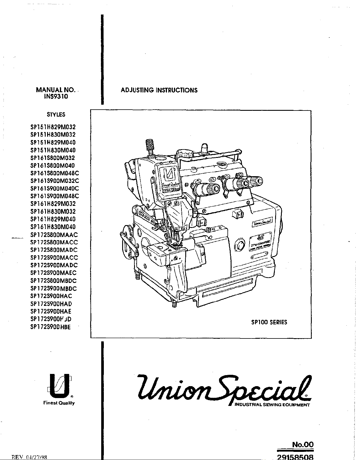
MANUAL
INS9310
SP151H829M032
SP151
SP151H829M040
SP151H830M040
SP161S800M032
SP161S800M040
SP161S800M048C
SP161S900M032C
SP1615900M040C
SP161
SP161
SP161
SP161H829M040
SP161
SP1725800MAAC
SP172S800MACC
SP172S800MADC
SP172S900MACC
SP172S900MADC
SP
172S900MAEC
SP172S800MBDC
SP
172S900MBDC
SP172S9QOHAC
SP172S900HAD
SP172S900HAE
SP
172S9QOP
SP172S900HBE
NO
..
SlYLES
H830M032
S900M048C
H829M032
H830M032
H830M040
;o
ADJUSTING
INSTRUCTIONS
SP100
SERIES
U.
Finest Quality
REV
O-I-/27/9R
No.OO
Page 2
A
SAFETY
RULES
TABLE
OF
CONTENTS
Poge
1-2
BEFORE OPERATION
CAUTIONS
1. INSTALLING
2.
3.
4. INSTALLING THE PEDALS
5. LUBRICATION
6.
7. THREADING THE MACHINE
8.
9.
10. DIFFERENTIAL FEED MECHANISM
11. KNIVES AND OVEREDGE WIDTH
12. SPECIFICATIONS
IN
OPERATION
MOTORPULLEYANDVBELT
ATTACHING THE BELT
ATTACHING NEEDLES
PRESSER FOOT PRESSURE AND
ADJUSTING
•.....
THE
FRAME SUPPORT PLATE
COVER
...•..
•..
THE
STITCH LENGTH
.....•••.
....•
liFTER
.•.
3
3
4
4
5
5
5
6
'
7
7
7
'
'
Page 3
Manual
This
adjusting
conjunction
Tl'lls
manual explains in
the
functions
items
with Union
discussed.
No.
manual
of
the
INS931
has
Special
detail
machine.
0 Adjusting Instructions
First
Edition
Union
Special
Corporation Rights Reserved In All Countries
been
prepared
Illustrated Parts
the proper
Illustrations
lo
seHing
are
used
Printed in
guide
you
Manual
for
each
to
show
Japan
PREFACE
P-RT9311.
for
the
SPI
Copyrightl993
By
October
while
1993
adjusting
the
SP100
of the componenls related
the
adjustments
and
rference letters
00 Series
Series machines. II
to
forming the stitch
are
Machines
used to
eon
and
completing
point
be
out
used
in
specific
Careful oHentlon
are
may
has
a slight
following
Opergfjng
sewing
these
II
8).
putting
each
machine
and
performance
Adjustments
of
sequence
This
manual
incorporate
On
the
machines.
Genergl
The
In
which
Annex
Before
1.
of
IMPORTANT!
to
fhe
instructions for
reliability designed
presented in
have
been
modification
pages
pjrectjons
machines
sewing
the
Before
sequence
an
adverse
comprised
will
be
described
machines
machines
is
only
permitted
pulling
operamg
and
so
effect
on
the
basis
of
configuration in illustraHons
found
iDusiralions
in
this
will
described
into
service
and
built into every Union Special machine.
that a
logical
on
the function
of
available
and
manual
be
built-In
in
this
after
taking
also
adjusting these machines will enable
progression
of
the
information.
fe!TTlinology used
SAFETY
are
manual
read
RULES
prohibited
have
conformed
notice
the
other
or
into
of
safety
is
occomplished.
related
Changes
part
numbers.
in
until
if
service
the
instructions
rules
perfs.
in
design
describing the adjustments for
has
been
ascertained,
with
the
EC
Council
carefully
and
read
and
instruction
you
to
maintain the superior
Some adjustments
the
by
qualified
and/or
from
Improvements
that
the
Directives
instructions.
operators.
the
motor
performed
the
SPlOO
sewing
(89/392/EEC,
The
starting
supplier.
out
may
Series
units
2.
Observe
3.
Each
in
foreseen.
4.
All
the
5.
All
bar
6.
When
threading,
for
clutch
the
machine
paragraph
safety
devices
appertaining
safety
devices
guard,
the
needle
gauge
when
main
motors
notional
is
only
"STYLES
safety
parts
the
power
without
safety
allowed
OF MACHINES"
must
be
in
devices
are
components
break
protection
are
exchanged
operator
by
switching
a start
rules
valid
to
be
position
is
leaves
off
the
inhibitor
used
when
not
of
shield,
(e.g.
the
main
if
for
your
as
foreseen.
of
this
manual.
the
machine
allowed.
the
sewing
handwheel-bell
needle,
workplace,
switch
is
necessory
country.
The
machines:
presser
and
or
disconnecting
to
foreseen
Another
is
ready
Fingerguard,
guard.
loot,
during
wait
unlit
use
use,
for
work
needle
service
the
the
of
going
or
plate,
work,
main
motor
the
particular
beyond
in
operalion.
needle
feed
the
plug.
has
the
lever
dog
machine
On
mechanically
stopped.
machine
description
The
operation
eyelet
guard,
and
bobbin)
must
is
described
is
not
without
needle
during
be
isolated
operated
as
Page 4
7.
Wear
8.
In
changes
safety glasses.
case
of
machine
are
made
conversions
at
your
own
and
risk.
changes
all
valid
safety
rules
must
be
considered.
Convarsions
and
Commissioning
9.
with
EC
10. The
Specjal
11. For
General
warning
Be sure
Operafing
the
or
by
11.1 For
11.2 For
11.3
11.4
11.5
Mgjntengnce
of
regulations.
hints in
to
observe
Pirectjons
following
pulling
When
When
out
threading
replacing
needle
leaving
For
maintenance
using
guard,
the
sewing
the
and
the
machine
the
main
needle(s),
sewing
folder,
the
dutch
Pirectjons
head
instructions
adhere
workplace
work.
has
plug:
tools
fabric
motors
to
looper,
without
is
prohibited
are
these
to
be
disconnected
spreader
such
as
guide
and
until
marked
with
&
Indications
etc.
needle.
etc.
when
the
actuation
such
time
one
of
Danget
and
to
from
the
presser
workplace
lock,
foot,
wait
as
these
the
generally
power
throat
is
unattended.
until
the
two
of
the
entire
symbols.
mjufY
supply
plale.
motor
sewing
fo
opetafive
applicable
by
fuming
looper.
is
stopped
unit
is
found
ot
•etvlee
regulations.
off
the
spreader,
totally.
to
•laff
main
feed
comply
switch
dog.
12.
Maintenance,
skilled
13.
special
Specjgl
14. Work
described
15.
disconnected
from
Stgndards
17. The
personnel
Any
work
on
skilled
Mgiolengnce
on
parts
in
Before
Exceptions
EN292-2 Safety
IEC204-3-1/EN60204-3·1
doing
compressed
ere
sewing
machines
repair
and
under
the
electrical
personnel.
Directions
and
equipment
the
applicable
maintenance
from
the
air
supply
only
allowed
described
of
machinery-basic
conversion
consideration
equipment
under
sections
and
compressed
(e.g.
for
adjusting
in
Electrical
for
works
(see
of
the
must
electrical
of
standard
repair
pneumatic
air
supply.
this
manual
concepts,
sewing
work
work
equipment
machines,
item
8) must
instructions.
be
done
by
tension is
sheet
on
the
In
case
equipment
and
function
are
built
general
of industrial
be
electricians
not
DIN
VDE
pneumatic
of
existing
with
checks
according
principles
units
and
done
permitted.
0105.
residual
air
lank),
machines.
systems.
only
by
troined
or
under
equipment,
air pressure
it has
to
done
by
to
the
following
for
design.
Port 3:
technicians
direction
Permissible
the
machine
after
be
removed
special
skilled
standards:
Particular
and
supervision
exceptions
has
disconnecting
by
personnel.
requirements
or
spe-cial
are
to
be
bleeding.
of
-2-
Page 5
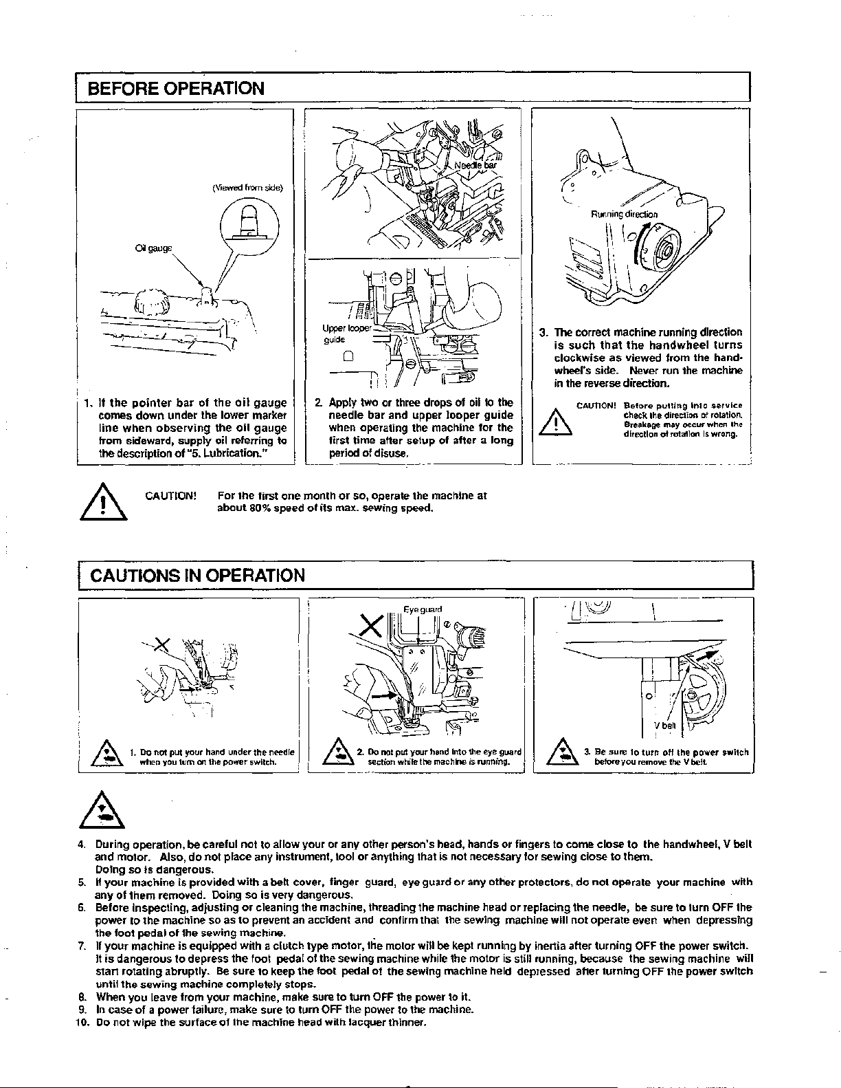
BEFORE OPERATION
(Viewed
from
1.
It
the
pointer
comes
line
when
from sideward,
the
description
bar
of
supply
of
u5.
the
the
oil referring
Lubrication."
down
under the lower marker
observing
oil
oil
side)
gauge
gauge
to
2.
Apply
two
needle
when operating the machine
first
period
or three drollS
bar
time
aHer setup
of
disuse.
and
upper
of
looper
of
after a
oil
to
guide
lor
long
the
the
3.
"IlK!'
correct machine running dlreelion
is
such
that
the
clockwise as viewed from the hand·
side. Never run the machine
wheel's
in
the
reverse direction.
.&
CAUTION!
handwheel
Before
check
lhe
Breaka""
direction
~ulllng
lnlg
direr:tion
may
occur
ol
rol"'lon
ot
turns
$ervlce
rotallon.
when
Is wrong.
lhe
For
lhe
CAUTION!
about
first
80%
CAUTIONS IN OPERATION
:A
~~
4.
5.
6.
7.
8.
9.
10. Do
1.
Do
not
put I"'Ur
hand
when you
tum
During operation,
and
motor. Also,
Doing
so
is
If
your
any
Before Inspecting, adjusting
power
the
If
your
It
is
start
until
When
In case
not
dangerous.
machine
of
them
removed. Doing
to
the
foot
pedal
machine
dangerous
rotating
the
sewing
you
leave from
of a power
wipe
is
machine
of
the sewing machine. .
is
to
abruptly.
machine completely stops.
the surface
under
on
the
po...,r
be
careful
do
not
place any instrument, tool
provided
so
as
equipped
depress
Be
your
failure, make sure to
of
the
switch. .
not
to allow
with
a belt cover,
so
is
or
cleaning the machine, threading the machine head
to
prevent an accident and confirm that the sewing machine
with
a clutch type motor, the motor
the
foot
sure
to keep
machine, make sure to
lhe
machine head with lacquer thinner.
one
month
or
speed
ol
n.....:tle I
'~-~---:"'ction
your
very dangerous.
pedal
olthe
the
tum
so, operate the machine
its max. sewing speed.
A
2.
Oo not
p~
your
han~
while the mac hr...
or
any other person's head,
or
anything that is not necessary
linger
guard, eye guard
sewing machine while the
foot
pedal ot the sewing machine held depressed after
tum
OFF the power
OFF the power to it.
to
the
~~tl1e
or
will
be kept running
machine.
at
~--------.,o
eye guard A
is
running. I
hands
or
any other protectors,
motor
is
~
L_
_______________
fingers
to
lor
sewing
or
replacing the needle,
will
by
inertia after
still running, because the sewing machine will
v~~~
3.
Be"""'
lo
1ur~
oH
before
you
come
close
close
do
not
to
to them.
not
operate
operate even when depressing
turning
be
OFF the power switch.
turning
I he power
remove the V
the handwheel, V belt
sure to
OFF the power
~It
your
machine with
tum
$Wl1C~
J
OFF the
switch
Page 6

1.
INSTALLING THE FRAME SUPPORT PLATE
I)
Attach
plate
blower
0.
case
8.
rubber cushion 0
10
frame support
L
I
0
~----
2) Install
3) Install upper waste chute 0
fram~
support
auach
lower waste
The installation
plate 0 directly
chute
the
9
chutes
of
56mm.
to
the table.
to
the left on
tO
the upper waste chute.
can
be
the
adjusted within a length
table,
and
then
of
2.
MOTOR PULLEY AND V BELT
90.5
85.5
(mm)
-
50Hz
sunken
I
V belt (inch}
Semi-
''"'
40
sunken
40
38
38
38
36
36
35
35
Fully-
''"'
36
34
34
34
32
32
32
30
30
I
Motor
outerdia. (rom)
135.5
125.5
120.5
110.5
100.5
'
~------
Sewing
(s.p.m.)
8500
8000
7500
7000
6500
6000
5500
5000
4500
speed
I
r--
I
I
Motor pulley
outerdia.
'
160.5
!50.5
140.5
130.5
120.5
110.5
100.5
60Hz
V belt
pulley
Semi-
~u11ken
''"
38
38
38
36
36
95.5 35 30
!!5.5
80.5
70.5
35
34
34
4.
(inch)
Fully-
sunken
''"
34
32
32
32
32
30
·w
30
I)
If
the
sewing
spc;:ed
of
the
machine
ex(;eed~
i~
3/4
or
with a clutch motor
W).
2)
UseanMtypeVbel!.
3)
The
sewing speeds obtnined by the use
of
diarnete~
4) Note that the effective diameter
the pulley of the machine head
mm.
7,500
~.p.m.,
the machine
~quipptd
lower, the machine
m<Jtor
lengths.
with a cluu:h molor
HP(550W).Ifitis7,500s.p.m.
is
of
Ill
table
on
the left shows the
pulleys with different
and
V belts with different
equipped
HP(400
of
of
is
50
Page 7

3. ATTACHING THE BELT COVER I I
l
I
i
L-------------------~
Install belt
cover 0 10
the machine head.
I 5. LUBRICATION
0
~~~b,~"'iJI
4. INSTALLING THE PEDALS
'=======;===~
)
(!}
I}
Install
stllning
seen
From
2}
Use
:m
S-shaped
to
presser lifting lever
pedal 0 on
the
operator.
hook 0 to
0.
the
left
connect
and
pre~~er
the
chain
lifter pedal
8 of
the
f)
on
the
presser lifter
right as
pedal
'------~--=---~~--~-
I)
Remo~e
oil
cap 0 . *Checking the cartridge filter
2)
Po(lrJU£<11\\:w
3) Supply oil UJJtilthe pointer
oil gauge
-1'-.
Caution Be careful
LJ..l
4) Remove oil drain cap 8 when dr.tining the oil reservoir.
•
lubrication
I)
Open
cloth
2) Remove plug@),
3}
Infiltrate silicon oil
aft~r
lubricating
Defri;o;
f}
is
observed
else
the
needle
plat~:
c.:o~r
and
al>o
the
needle cooler.
Oil No.2
troubles
cooler
and
supply silicon
into the oil
into
bar
a!mo~t
from
the
not
to
due
supply silicon
the
oil
reservoi[
reoches the upper red marker line when become clogged with dust.
~ide.
exceed
the
to
excessive
upper red marker
lubrication may resuh. wear
" "
'·'
oil
from
section
e.
oiL
felt
if
the
machine
is
started immediately
fine,
r I
~0_~~~:::::l_j
and
1.
After a
long
period
of
us.tge,
If
the
machine
i:;
left
in
this
otatc,
or
pass lhrough can ridge filter 0 ,
out
abnonnally. or a seizure
* Car1ridge filler 0 should nonnally
every
six
months.
and
cleaned
2.
How
to
inspect
the
I) Remove
2) Remove
(Caution) H top cover 0 Is shifted sideward, the
3)
4) Re-inscn canridge filter 0
firot
screw~
it
comes
of[
pointer
Remove cartridge
found
to
be
replace
can
relllm the
(IJld
tighten
car1ridge
oil
di~charging
8.
bar
and
abnonnal, clean
ridge
filter
cover_
Do not forget
them
up.
filter and replace
>crew
and
lift
top
the
cartridge filter may be
filter 0 (IJld
the
0.
into
replacing
cartridge filter 0
the
and
may
or
replaced accordingly.
f).
cover 0 just above
check
relevant components, or
its
to
put back the setscrews
it
dirty oil may
the
machine may
result.
be
checked once
it
oil
n.
If the filter
proper
po-;ition
may
fail
until
amount
damaged.
and
10
is
Page 8

I 6. ATTACHING NEEDLES
SWUcl\-ott main switch
clutch m01ors wl!.hollt attua\101\
stopped
tolall~l
The
standard needle
looper
may
Anach
the
needle.~
I) Bring needle
2)
Loosen
needle clamp screw
the
oper<llor's
3) Tighten
I
7.
THREADING THE MACHINE
Switch-oft
motms
totaHy!
Thread
the
is
be
required
according to the following procedure;
damp
side.
the
needle clamp screw 0 _
mBin
without
machine according
belore
allar::lllng
"0Cx27
to
be
adjusted.
#II."
0 to the highest
8,
and fully
switch
befe>re
actu!lllon
toc:k
to
the threading
You
throadlng!
wait
needles!
to~k
walt
can
If
sewing
po~ition.
until
unHitlla
also
need
insert
Whn
the
motor
chaJt
W~"
use
the Delli
to
the
using
has
g'tven
molor
needle
be
stopl""d
using
has
carried
into
clutch
below.
needle.
ln
this
out
with a finely-adjusted
the
needle
clamp hole
(The
same
chart is
c-ase,
how(;!ver,
on
the
clearance provided between
thread
tension,
with
the
needle recess facing backwards
the
irr~ideofthe
use
looper
the
DCx27 needle.
cover.)
SP172
the
needle and
as
viewed
!he
from
SP161
* How
When
10
thread
lhe
the
needle cooler is used
needle
thread
silicon
oil
tank
When the nee!Je cooler
not
used
1s
lntermcdlal" t'ucad gu;,Je
,,
·~
= \
:\@
\.:::......J.'
~.-----
(Caution)
When using an untwisted
thread such as wooly
thread
or
weak thread, do
not wind it round lhe inter·
mediate
thread
guide.
I
~
nylon
Pass
the
center pawl.
thread under the
Pass
the
thread
center pawl.
above
the
-6-
Page 9

8. PRESSER FOOT PRESSURE
AND LIFTER
9. ADJUSTING THE STITCH LENGTH
I) Adjust the pressure
0 and turning presser
When the adjust screw
increase. When
wi!l decrease. After
without
faiL
2)
To
open
presser
of
the presser
foot
is
turned clockwise,
it
is
turned oounterdockwise,.
lhe
adjustment.
foot
f)
sideward, lower presser
foot
adjust screw
by
loosening tin;t
0.
the
pressure
!he
be
sure to tum nut 0
leverO.
10.
DIFFERENTIAL FEED MECHANISM
pressure
bar
lifting
nut
will
Switch-off main switch before
When
using
clutch
the motor
I) Slowly tum the handwhecl
will
find
a )Xlint at
2) Wnh the above condition maintained, align the desired scale mark on !he
handwheel with
3)
Reset
the
pushbuuon after setting
has
which
mark 8 on
motors
stopped totally!
as
you
keep depressing pushbutton
the
pushbutton goes
the
belt
cover.
the
dial.
I)
Loosen
difft:rential
Move
leverO
for
gathering stitch.
2) When the differential feed adjusting lever is
se1
to graduationS, the machine will perfonn
stretching with a differential
I :0.8. When the lever is set to graduation
0,
the
differential feed ratio between the main
feed dog and the differential
I
:I.
3)
The
maximum
gathering
depending on the adjust-ment
mechanism
graduations beyond
selling
with-out
is 1
actuation
in
farther.
feed
kx:k
up
for stretching stitch
differential
:2.3
(it
of
the
sewing machine). The
0 are used as reference.
the stitch length!
lock
wait until
8,
and
nul
8.
or
down
feed ratio
ked
dog
will
feed
can
ratio
be
set to I :4.5
of
the
in1emal
you
for
of
be
-7-
Page 10

11. KNIVES AND OVEREDGE WIDTH
Switch-oft main switch betore adjusting
of
knives!
actuation
totally!
•
Height
of
Loosen setscrew 8
its
edge
• Height of
lJ:Josen setscrews
knife
knife is
• Dveredge
Ove~edge
parts
slightly larger !han the knife cut width.)
To
change the overedge width:
l)
Loosening setscrew 0 , push lower knife 0
and fix
2) Loosen setscrew 0 and move upper knife 8 as required, then
fix
3)
Lower the llpper knife to
lower
is flush with
the
8 overlaps lower knife 0 by 0.5
at
its lowert point.
widths
widths
or
by using subclass models. (The ovcrcdgc width will
it.
it.
When
using
lock
wait
knife
and
adjust
the
the
throat plate surface.
until
height
clutch
the
motor
or
lower
upper knife
0,
0 and perform adjustment so that upper
IO
I mm when the upper
of
2 through 4.8
mm
are
provided
its
lowest point and loosen
@. Tighten setscrew 0 when the lower knife comes
with the upper knife.
1.
Be
sure
to
tighten
screw
(j)
motors
has
knife 0
by
before
the
height
without
stopped
so
that
changing
the
to
the
left
set~crcw
in
contact
operating
machine.
(caution) knives
• Resharpening the lower
Whefl
figure lefr.
2.Aiter
the
lower knife
knives.
the
completion
cut
a thread to
knife
ha~
become dull, rcsharpen
of
adjustment,
ch~k
for
sharpness
it
as shown in the
make
of
the
the
be
12. SPECIFICATIONS
Sewing
speed
(Ma."<.)
Stitch length
Needle
guagc
Overedge
-=------
Differemial feed
Needle
Presser foot lifl
Presser fool
width
lift
..
ratio
--·
---------------------------------------- ----------------------------------------
·-·---
---------------
c-
SP161
8,500s.p.m. j" 8,000s.p.m.
(exduding
u~u-
..
--
···--
-··~·-:-:--:'-:--=--·-·-
Gathering stitch 2.3 (Max. I :4.5 ), Stretching stitch I :0.8
DC x 27
--~..?-~~---
···--·-
-------------
--"''''cdc"c"c;""•cw~m;c'c'=""~'~::=':cm="'c;c'=''=l-------------1
(Smmlard)
JUKI
New
some
subclass models)
0.8-
3.5
mm
DC
_l
______
Defrix
x 1
may
-------
Oil No. 2
be used
SPI72
2.0,
2.4
mm
~D.•~u-
..
~·-.~.
7mm
Page 11

OfToc~
usr
only
UNION
PRODUCT
(Plea$<
$Ubmit
one
SPECIAL
CORPORATION
INSTALLATION
fl'11m
ea<ll
maoblne lnttalltd and rompltle
REPORT
alllkrms)
Offiu
use only
Adjuster
C11stomer
Address
Telephone Sales Represenmtive
Contact
SURVEY
Rate
each
of
the
items
listM, circle
Highest=
5 (Very SatisfiM):
Date Installed
Machine Style
Serial
Installation
(in hours) Style
Sales
Territory
RATING
one,
Lowest=
number
PROCEDURE
according
5 = Very Satisfied 2 = Dissatisfied*
=Very
4 = Satisfied I
Dissatisfied* (*=Explanation Requested)
EVALUATION
The
A.
carton and packing materials used
are
correct, all accessory items were received
5 4 2 I
Sewing
B.
c.
The
D.
There
E.
All
during initial operation
F.
Machine
The
G.
The
H.
your
machine received in good condition No external parts
5
4
external painted surface was not scratched and showed
4
oil
at
any external part
4
was
no
excessive accumulation
5
of
5
screws and securing devices were tight Adjustable
of
the machine.
4 2
the factory box with only minor adjustment required.
4 2 1
sewed
on
your
operation
5
out
5
of
instruction manual was infonnative and provided clear, easy
4
table stand,
use
of
the machine.
5
motor
and accessory items provided for installing the machine were
5 4 2 I
I.
In
actual operation,
No
unusual vibration was detected at the machine, motor
under
production standards, at
maximum
or
5 4
Please
provide
the
reasons
you
are
not
Item Explanation
Time
to
the
degree
of
satisfaction
I (Very DissatisfiM)
in
good condition.
or
accessories were damaged in shipment.
2 I
no
signs
of
rust at point.
2 I
of
lhe machine.
2 1
pans
were properly secured and did not
1
to
follow instructions.
2 I
of
proper design and suitable for
speed,
the
noise emitted was at acceptable levels.
peripheral devices.
2
satisfied
1
with
this
product.
Inspector
become
1oose
(If
rno~
space
is
rcquiR;d,
please
INSREPF.\1.
WK
Please enter operational
Page 1
data
FPKOOO
usc
back of form.)
on back or form.
Rev. OJI893
Page 12

Needle thread
Looper thread
Stitches per inch
Material
Needle size
Speed
Oil used
(brand & type)
UNION
SPECIAL
PRODUCT
OPERATIONAL
CORPORATION
INSTALLATION
DATA
REPORT
[
Fir
thr""d
•
como labels here ir possible.)
Sewing operation perfonned:
Additional comments:
. .
Threa.d brattd and
(if labels are
Mt
type
furnished}
hg<2
--
Page 13

NOTES
Page 14

NOTES
Page 15

Page 16

WORLDWIDE
SALES
AND
SERVICE
Union Special Corporation maintains sales
out the
WOI1d.
These
offices will aid you in the selection of the right sewing
equipment for
representatives
to serve your needs promptly
there is a
yOIJ
and
quallled
particular operation. Union Special Corporation
service technicians
and
representative to serve you.
Corporate
Office:
are
efticienHy. Whatever your location,
One
Huntley,
Phone: 847•669•5101
Hax:847•669•4454
European Dislribufion Center:
Union Special GmbH
Raiffeisenstrasse 3
0·71696
Tel:
Fax:49•07141•247•100
and
service
fac~ilies
facfory
trained
Union Special Plaza
IL
60142
MOglingen,
and
49•07141•247•0
through·
are
able
Germany
Brussels, Belgium
Charlotte, N.C.
El
Paso,
TX
Hong Kong, China
Huntley,
ll
leicester, England
Lille, France
Miami,
Milan,llaly
FL
M6glingen, Germany
Montreal,
Quebec
Osaka, Japan
Santa
Fe
Springs, CA
Other
Representatives
all parts
of
the
world.
throughout
Finest Quality
 Loading...