

Union Special PT9805 Parts Book
ILLUSTRATED PARTS MANUAL
REV 5-31-01
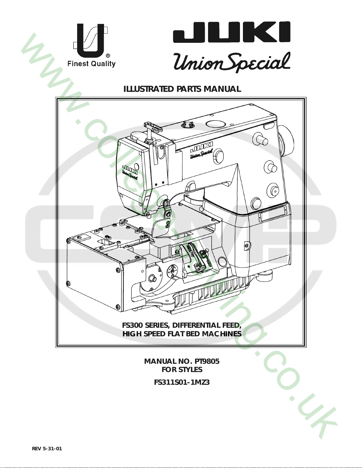
FS300 SERIES, DIFFERENTIAL FEED,
HIGH SPEED FLAT BED MACHINES
MANUAL NO. PT9805
FOR STYLES
FS311S01-1MZ3
Manual No. PT9805 llustrated Parts List for FS300 Series Machines
Second Edition Copyright 2001
By
Union Special Corporation Rights Reserved In All Countries
This parts manual has been prepared to assist you in locating individual parts or assemblies on FS300 Series machines. It
can be used in conjunction with Union Special Engineer's Manual EN9424.
It is the desire of Union Special that each machine run at its optimum performance. Parts listed in this manual are
designed specifically for your machine and are manufactured with utmost precision to assure long lasting service.
This manual has been comprised on the basis of available information. Changes in design and/or improvements may
incorporate a slight modification of configuration in illustrations or part numbers.
On the following pages are illustrations and terminology used in describing the parts used on FS300 Series machines.
Printed in U.S.A. May 2001
PREFACE
2
CONTENTS
PREFACE ................................................................................................................................................................... 2
SAFETY RULES ............................................................................................................................................................ 4
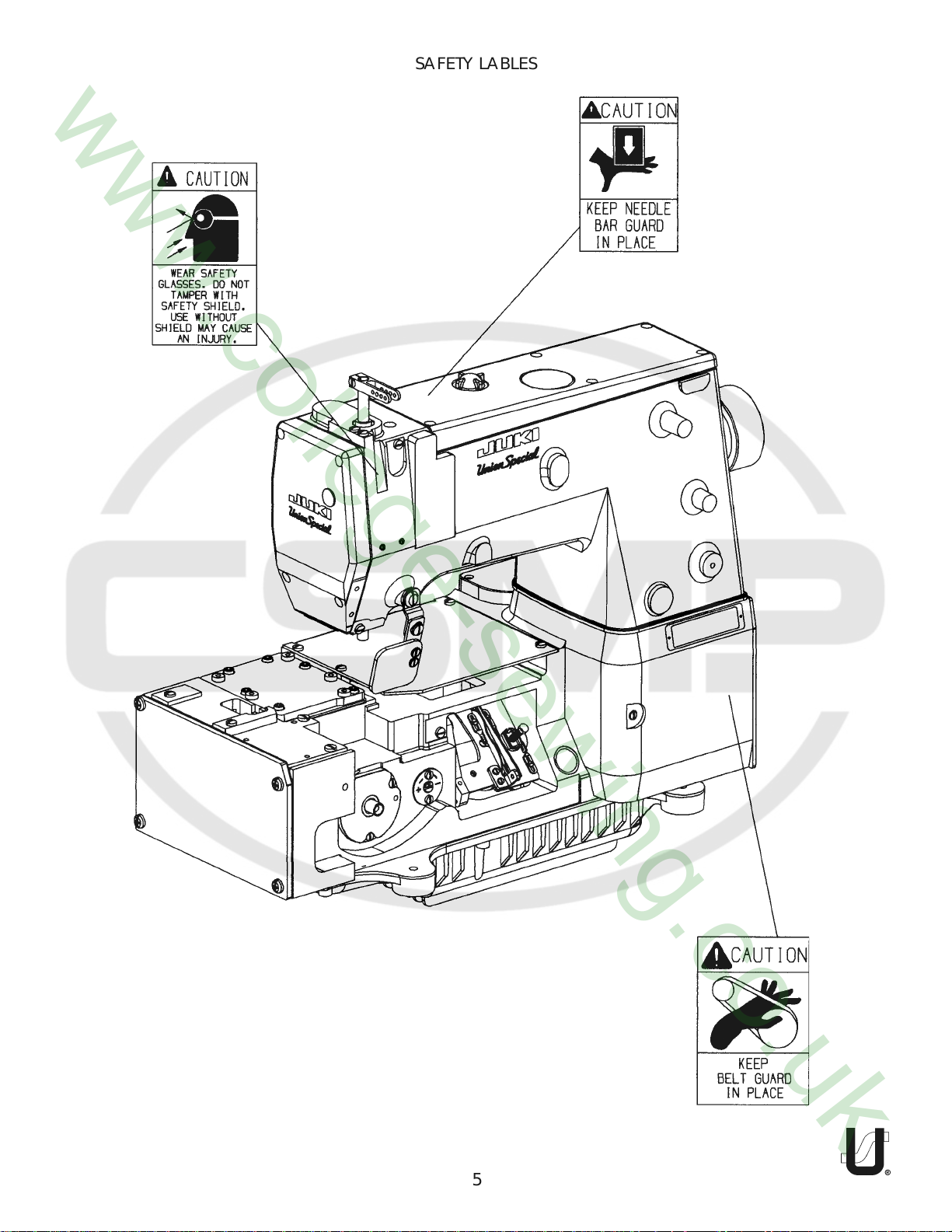
SAFETY LABLES .......................................................................................................................................................... 5
BUSHINGS.................................................................................................................................................................. 7
NEEDLE BAR .............................................................................................................................................................. 9
UPPER MAIN SHAFT ................................................................................................................................................ 11
COVERS, UPPER ARM ........................................................................................................................................... 13
LOWER MAIN SHAFT............................................................................................................................................... 15
LUBRICATION, OIL TUBING & OIL PUMP ............................................................................................................... 17
LOOPER DRIVE........................................................................................................................................................ 19
NEEDLE GUARD ...................................................................................................................................................... 21
LOOPER THREAD TAKE-UP ..................................................................................................................................... 23
COVERS, LOWER BED ............................................................................................................................................ 25
PULLER DRIVE ASSEMBLY ....................................................................................................................................... 27
ACCESSORIES ......................................................................................................................................................... 29
NUMERICAL INDEX OF PARTS................................................................................................................................ 30
NOTES ...................................................................................................................................................................... 31
NOTES ...................................................................................................................................................................... 32
NOTES ...................................................................................................................................................................... 33
3
SAFETY RULES
1. Before putting the machines described in this manual into service, carefully read the instructions. The
starting of each machine is only permitted after taking notice of the instructions and by qualified
operators.
IMPORTANT! Before putting the machine into service, also read the safety rules and instructions from the
motor supplier.
2. Observe the national safety rules valid for your country.
3. The sewing machines described in this instruction manual are prohibited from being put into service until
it has been ascertained that the sewing units which these sewing machines will be built into, have
conformed with the EC Council Directives (89/392/EEC, Annex II B).
Each machine is only allowed to be used as foreseen. The foreseen use of the particular machine is
described in paragraph “STYLES OF MACHINES” of this instruction manual. Another use, going beyond
the description, is not as foreseen.
4. All safety devices must be in position when the machine is ready for work or in operation. Operation
of the machine without the appertaining safety devices is prohibited.
5. Wear safety glasses.
6. In case of machine conversions and changes all valid safety rules must be considered. Conversions
and changes are made at your own risk.
7. The warning hints in the instructions are marked with one of these two symbols:
8. When doing the following the machine has to be disconnected from the power supply by turning off
the main switch or by pulling out the main plug:
8.1 When threading needle(s), looper, spreader etc.
8.2 When replacing any parts such as needle(s), presser foot, throat plate, looper, spreader, feed
dog, needle guard, folder, fabric guide etc.
8.3 When leaving the workplace and when the workplace is unattended.
8.4 When doing maintenance work.
8.5 When using clutch motors without actuation lock, wait until the motor is stopped totally.
9. Maintenance, repair and conversion work (see item 8) must be done only by trained technicians or
special skilled personnel under consideration of the instructions.
10. Any work on the electrical equipment must be done by an electrician or under direction and supervision
of special skilled personnel.
11. Work on parts and equipment under electrical power is not permitted. Permissible exceptions are
described in the applicable sections of standard sheet DIN VDE 0105.
12. Before doing maintenance and repair work on the pneumatic equipment, the machine has to be
disconnected from the compressed air supply. In case of existing residual air pressure, after disconnect-
ing from compressed air supply (i.e. pneumatic equipment with air tank), the pressure has to be
removed by bleeding.
4
SAFETY LABLES
5
6
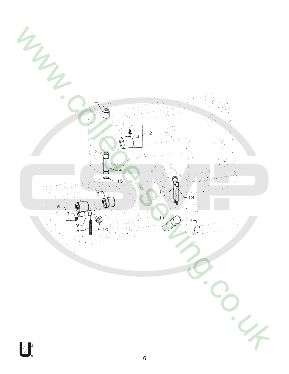
BUSHINGS
Ref.
No.
Part No.
Description
Amt.
Req.
1.
50654B
2.
50344AS
3.
SQ1110401MZ
4.
50654C
5.
50344BF
6.
50344BE
7.
SQ1110401MZ
8.
WO3
9.
50368AB
10.
50344E
11.
50393GE
12.
22571L
13.
50393FU
14.
50393EY
15.
660-1019
Bushing, for needle bar, upper .....................................................................
Bushing, front ...............................................................................................
Fitting .....................................................................................................
Bushing, for needle bar, lower ......................................................................
Bushing, for lower mainshaft, right ...............................................................
Bushing, for lower mainshaft, left .................................................................
Fitting .....................................................................................................
Yarn, See Chart ............................................................................................
Bushing, for needle lever, See Chart ............................................................
Bushing ........................................................................................................
Oil Sight Gauge ............................................................................................
Screw, for drain plug ....................................................................................
Fitting, oil tube ..............................................................................................
Fitting, filter ..................................................................................................
"O"Ring .........................................................................................................
1
1
1
1
1
1
1
1
1
1
1
1
1
1
1
7
8
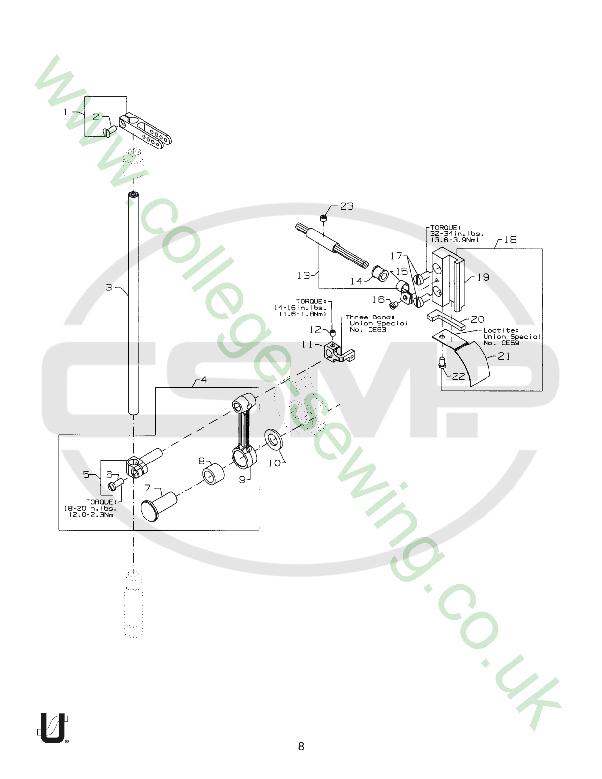
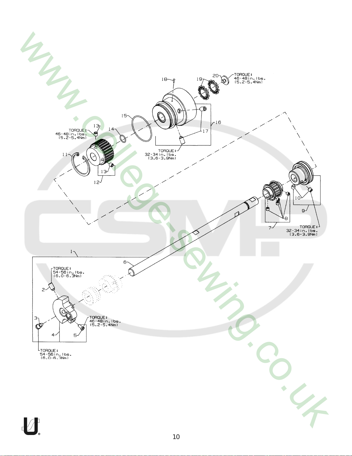
NEEDLE BAR
Ref.
No.
Part No.
Description
Amt.
Req.
1.
2.
3.
4.
5.
6.
7.
8.
9.
10.
11.
-
12.
13.
14.
15.
16.
17.
18.
19.
20.
-
21.
22.
23.
K74233
18C1419
K74234
50345W
50355AM
SS7111120TP
50352
661-259B
50355AN
50351A
50354F
CE63
SS8110422TP
29476TC
50393JZ
50393JW
SS6090440SP
SS6121010SP
29476VN
50338
666-328
CE59
50338A
SS6090620SP
SS8120410SP
Needle Bar Eyelet .........................................................................................
Screw .....................................................................................................
Needle Bar ...................................................................................................
Connecting Rod Assembly ...........................................................................
Needle Bar Clamp .................................................................................
Screw ...............................................................................................
Pivot Pin .................................................................................................
Needle Bearing Cage ............................................................................
Connecting Rod ....................................................................................
Washer .........................................................................................................
Slide Block ....................................................................................................
Three Bond Adhesive, (not shown), for slide block .......................................
Screw ...........................................................................................................
Oil Tube Assembly ........................................................................................
Oil Tube ........................................................................................................
Hose Clamp .................................................................................................
Screw, for oil tube assembly .........................................................................
Screw ...........................................................................................................
Slide Block Guide and Cover Assembly ........................................................
Guide, for slide block .............................................................................
Felt, for slide block ..................................................................................
Loctite Adhesive, (not shown), for felt ...................................................
Cover, for guide .....................................................................................
Screw .....................................................................................................
Screw ...........................................................................................................
1
1
1
1
1
1
1
1
1
1
1
-
1
1
1
1
1
2
1
1
1
-
1
1
1
9
10
 Loading...