

Union Special PT0503 Parts Book
ILLUSTRATED PARTS LIST
CATALOGO ILUSTRADO DE PARTES
HIGH SPEED ONE NEEDLE, THREE THREAD, PLAIN FEED
OVERSEAMING SEWING MACHINES
MAQUINAS INDUSTRIALES DE COSER ALTA VELOCIDAD, UNA AGUJA,
TRES HILOS , CAMA PLANA
MANUAL NO. PT0503
STYLES/ ESTILOS
39500TYA
39500TYB
02/25/09
INSTRUCTIONS AND ILLUSTRATED PARTS LIST
MANUAL NO. PT0503
FOR 39500 SERIES MACHINES
INSTRUCCIONES Y LISTADO ILUSTRADO DE
CATALOGO NO. PT0503
PARTES PARA MAQUINAS ESTILO 39500
First Edition Copyright 2006
by
Union Special
Rights Reserved in All Countries
PREFACE
This catalog has been prepared to guide you while
operating 39500 series machines and arranged to simplify
ordering spare parts.
This catalog explains in detail the proper settings for
operation of the machines. Illustrations are used to show
the adjustments and reference letters are used to point
out specific items discussed.
Careful attention to the instructions and cautions for
operating and adjusting these machines will enable you
to maintain the superior performance and reliability
designed and built into every Union Special bag sewing
machine.
Adjustments and cautions are presented in sequence so
that a logical progression is accomplished. Some
adjustments performed out of sequence may have an
adverse effect on the function of the other related parts.
This manual has been comprised on the basis of available
information. Changes in design and / or improvements
may incorporate a slight modification of configuration in
illustrations or cautions.
Primer Edición © 2006
por
Union Special
Derechos Reservados en todos los países
INTRODUCCION
Este catálogo fue preparado para guiar al usuario en la
operación de maquinas de la serie 39500 y ayudar a
simplificar la elaboración de los pedidos de los repuestos.
Este catálogo explica detalladamente los ajustes para la
operación de la maquina. Las ilustraciones sirven para
demostrar los ajustes y las letras en referencia indican
los puntos específicos discutidos.
Una cuidadosa atención a las instrucciones y las
precauciones operando y ajustando estas maquinas le
va a permitir mantener el mejor funcionamiento y la
confiabilidad que caracteriza las maquinas cerradoras
de sacos de Union Special.
Los ajustes y precauciones son presentados en
secuencia para que se consiga una progresión lógica.
La ejecución de algunos ajustes fuera de la secuencia
puede causar un efecto adverso para el funcionamiento
de otras partes relacionadas.
Este manual se comprende a base de la información
actual. Cambios en diseño y/o mejoras pueden significar
leves modificaciones de la configuración de las
ilustraciones o precauciones.
On the following pages will be found illustrations and
terminology used in describing the instructions and the
parts for your machine.
In addition to the instructions and to the mandatory rules
and regulations for accident prevention and en-
vironmental protection in the country and place of use
of the machine / unit, the generally recognized technical
rules for safe and proper working must also be observed.
The instructions are to be supplemented by the
respective national rules and regulations for accident
prevention and environmental protection.
En las paginas siguientes se encuentran ilustraciones y
terminologías usadas en la descripción de las
instrucciones y las piezas de la maquina.
Adicionalmente a las instrucciones, las reglas y
regulaciones obligatorias para prevenir accidentes y la
protección ambiental del país y lugar donde se encuentra
la maquina/unidad, hay que considerar las reglas
técnicas para un trabajo seguro y adecuado.
Las instrucciones hay que complementarlas con las
respectivas reglas y regulaciones nacionales contra
accidentes y protección del ambiente.
2
TABLE OF CONTENTS
INDICE
PAGE
PREFACE 2
INTRODUCCION 2
SAFETY RULES / REGLAS DE SEGURIDAD 4-5
IDENTIFICATION OF MACHINES / IDENTIFICACION DE LAS MAQUINAS 6
APPLICATION OF THIS CATALOG / APLICACION DE ESTE CATALOGO 6
STYLES OF MACHINES / ESTILOS DE LAS MAQUINAS 6
OILING / LUBRICACION 7
NEEDLES / AGUJAS 7
CHANGING NEEDLES / CAMBIO DE AGUJAS 9
THREAD STAND / PORTA CONOS 9
THREADING / ENHEBRADO 9
TO THREAD LOWER LOOPER / ENHEBRAR EL LOOPER INFERIOR 9
TO THREAD UPPER LOOPER / ENHEBRAR EL LOOPER SUPERIOR 10
TO THREAD NEEDLE / ENHEBRAR LA AGUJA 10
THREAD TENSION / TENSION DE LOS HILOS 10
PRESSER FOOT PRESSURE / PRESION DEL PIE PRENSATELAS 11
FEED ECCENTRICS / EXENTRICO DEL TRANSPORTE 11
ASSEMBLING AND ADJUSTING SEWING PARTS / MONTAJE, AJUSTE PIEZAS QUE FORMAN LA COSTURA 11
SETTING THE NEEDLE / AJUSTE DE LA AGUJA 11
SETTING THE LOWER LOOPER / AJUSTE DEL LOOPER INFERIOR 12
SETTING THE REAR NEEDLE GUARD / AJUSTE DEL GUARDA AGUJAS TRASERO 12
SETTING THE FRONT NEEDLE GUARD / AJUSTE DEL GUARDA AGUJAS DELANTERO 12
SETTING THE UPPER LOOPER / AJUSTE DEL LOOPER SUPERIOR 12
SETTING THE UPPER LOOPER (CONTINUED) / AJUSTE DEL LOOPER SUPERIOR (CONTINUACION) 13
SETTING THE FEED DOG / AJUSTE DEL TRANSPORTADOR 13
SETTING THE STITCH LENGTH / AJUSTE DEL LARGO DE LA PUNTADA 14
SETTING THE PRESSER FOOT / AJUSTE DE LA PRESION DEL PIE PRENSATELAS 14
STARTING TO OPERATE / ARRANQUE DE LA MAQUINA 15
UPPER LOOPER THREAD CONTROL / AJUSTE DEL HILO DEL LOOPER SUPERIOR 15
NEEDLE THREAD CONTROL / AJUSTE DEL HILO DE LA AGUJA 15
LOWER LOOPER THREAD CONTROL / AJUSTE DEL HILO DEL LOOPER INFERIOR 16
POSITIONING THE PURL / AJUSTE DE LA POSICION DE LA UNION DE LOS HILOS DE LOS LOOPERS 16
THREAD TENSIONS / TENSIONES DE LOS HILOS 16
SPECIAL ADJUSTMENTS / AJUSTES ESPECIALES 17
TO REMOVE CRANKSHAFT / DESMONTAJE DEL CIGUEÑAL 17-18
MAINFRAME, MISCELLANEOUS COVERS AND PLATES 20-21
CUBIERTA PRINCIPAL, CUBIERTAS MISCELANEAS Y PLACAS 20-21
MAINFRAME, MISCELLANEOUS COVERS AND PLATES 22-23
CUBIERTA PRINCIPAL, CUBIERTAS MISCELANEAS Y PLACAS 22-23
CRANKSHAFT MECHANISM AND BUSHINGS 24-25
MECANISMO DEL CIGUEÑAL Y BOCINAS 24-25
NEEDLE DRIVE AND FEED MECHANISM 26-27
ACCIONADOR DE LA AGUJA Y DIENTES DE ARRASTRE 26-27
UPPER AND LOWER LOOPER DRIVING PARTS 28-29
PARTES DE ACCIONAMIENTO DE LOS LOOPERS SUPERIOR E INFERIOR 28-29
THROATPLATE, PRESSER FOOT, PRESSER FOOT LIFTER AND NEEDLE GUARDS 30-31
PLANCHA DE AGUJA, PIE PRENSATELAS, LEVANTADOR DEL PIE PRENSATELAS Y GUARDA AGUJAS 30-31
THREAD TENSION BRACKET, HEMMER AND MISCELLANEOUS EYELETS 32-33
SOPORTE DE LA TENSION, DOBLADILLADOR Y GUIA HILOS MISCELANEOS 32-33
THREADSTAND 34-35
PORTA CONOS 34-35
NUMERICAL INDEX OF PARTS 36-37
INDICE NUMERICO DE PARTES 36-37
NOTES / NOTAS 38-39
3
SAFETY RULES
INDICACIONES DE SEGURIDAD
1. Before putting the machines described in this manual into
service, carefully read the instructions. The starting of
each machine is only permitted after taking notice of the
instructions and by qualified operators.
IMPORTANT! Before putting the machine into service, also
read the safety rules and instructions from the motor
supplier.
2. Observe the national safety rules valid for your country.
3. The sewing machines described in this instruction manual
are prohibited from being put into service until it has been
ascertained that the sewing units which these sewing
machines will be built into, have conformed with the
provisions of EC Machinery Directive 98/37/EC, Annex II
B.
Each machine is only allowed to be used as foreseen.
The foreseen use of the particular machine is described
in paragraph "STYLES OF MACHINES" of this instruction
manual. Another use, going beyond the description, is
not as foreseen.
4. All safety devices must be in position when the machine
is ready for work or in operation. Operation of the
machine without the appertaining safety devices is
prohibited.
1. Antes de poner en marcha las maquinas descritas
en este manual, hay que leer cuidadosamente las
instrucciones. El arranque de cada maquina
solamente se permite después de haber leído las
instrucciones y por personal calificado.
IMPORTANTE! También hay que leer las reglas de
seguridad y las instrucciones del fabricante del
motor.
2. Observe las reglas nacionales de seguridad
que rigen para su país.
3. No se puede poner en marcha la maquina descrita
en este manual hasta que se confirme que la unidad
de coser esta conforme con el reglamento del
Directivo de las Maquinas de la Comunidad Europea
98/37/EC, Anexo II B.
La maquina solamente se puede utilizar para su
uso previsto. El uso previsto esta descrito en el
capitulo ESTILO DE MAQUINAS de este manual de
instrucciones. Otro uso, diferente de la descripción,
no esta previsto.
4. Todos los dispositivos de seguridad tienen que
estar en su sitio cuando la maquina este lista para
trabajar u operando. La operación de la maquina
sin los dispositivos de seguridad esta prohibida.
5. Wear safety glasses.
6. In case of machine conversions and changes all valid
safety rules must be considered. Conversions and
changes are made at your own risk.
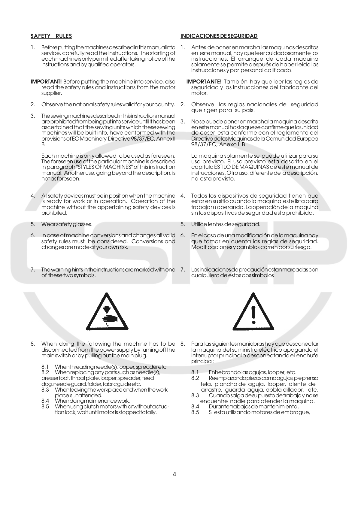
7. The warning hints in the instructions are marked with one
of these two symbols.
8. When doing the following the machine has to be
disconnected from the power supply by turning off the
main switch or by pulling out the main plug.
8. 1 When threading needle(s), looper, spreader etc.
8.2 When replacing any parts such as needle(s),
presser foot, throat plate, looper, spreader, feed
dog, needle guard, folder, fabric guide etc.
8. 3 When leaving the workplace and when the work
place is unattended.
8. 4 When doing maintenance work.
8.5 When using clutch motors with or without actua-
tion lock, wait until motor is stopped totally.
5. Utilice lentes de seguridad.
6. En el caso de una modificación de la maquina hay
que tomar en cuenta las reglas de seguridad.
Modificaciones y cambios corren por su riesgo.
7. Las indicaciones de precaución estan marcadas con
cualquiera de estos dos simbolos
8. Para las siguientes maniobras hay que desconectar
la maquina del suministro eléctrico apagando el
interruptor principal o desconectando el enchufe
principal:
8.1 Enhebrando las agujas, looper, etc.
8. 2 Reemplazando piezas como agujas, pie prensa
tela, plancha de aguja, looper, diente de
arrastre, guarda aguja, dobla dillador, etc.
8. 3 Cuando salga de su puesto de trabajo y no se
encuentre nadie para atender la maquina.
8. 4 Durante trabajos de mantenimiento .
8.5 Si esta utilizando motores de embrague,
4
9. Maintenance, repair and conversion work (see item 8)
must be done only by trained technicians or special
skilled personnel under condsideration of the
instructions.
9. Mantenimiento, reparación y trabajos de conversión
(vease No. 8) solamente pueden ser efec tuados por
técnicos entrenados o por personal especializado
bajo consideración de las instrucciones.
Only genuine spare parts approved by UNION SPE-
CIAL have to be used for repairs. These parts are
designed specifically for your machine and manufac-
tured with utmost precision to assure long lasting service.
10 . Any work on the electrical equipment must be done by
an electrician or under direction and supervision of
special skilled personnel.
11 . Work on parts and equipment under electrical power is
not permitted. Permissible exceptions are described in
the applicable section of standard sheet EN 50 110 /
VDE 0105.
12. Before doing maintenance and repair work on the
pneumatic equipment, the machine has to be discon-
nected from the compressed air supply. In case of
existing residual air pressure after disconnecting from
compressed air supply (e.g. pneumatic equipment with
air tank), the pressure has to be removed by bleeding.
Exceptions are only allowed for adjusting work and
function checks done by special skilled personnel.
Solamente repuestos originales y aprobados por
Union Special pueden ser utilizados para
reparaciones.
10 . Cualquier trabajo con el equipo eléctrico tiene que
ser ejecutado por un electricista o bajo la supervisión
de personal especialmente entrenado.
11 . No esta permitido trabajar en piezas y equipos con la
electricidad conectada. Excepciones permitidas están
descritas en EN 50110 / VDE 0105.
12. Antes de hacer mantenimiento o reparaciones del
equipo neumático, hay que desconectar la maquina
de la alimentación del aire comprimido. En el caso
que exista una presión de aire residual después de
desconectar la maquina (por ejemplo equipos con
tanques de aire), la presión tiene que ser eliminada
abriendo las válvulas. Excepciones están solamente
permitidas para trabajos de ajuste y revisión de
funciones por personal especialmente entrenado.
5
IDENTIFICATION OF MACHINES
IDENTIFICACION DE LAS MAQUINAS
Each UNION SPECIAL machine is identified by a style number on a
name plate on the machine. Style numbers are classified as standard
and special. Standard style numbers have one or more letters suffixed,
but never contain the letter "Z". Example: "Style 39500TYB". Special
Style numbers contain the letter "Z".
When only minor changes are made in a standard machine, a "Z" is
suffixed to the Standard Style number.
Example: "Style 39500TYB 3280 A".
Styles of machines similar in construction are grouped under a class
number which differs from the Style number, in that it contains no
letters.
Example: "Class 39500"
APPLICATION OF CATALOG
This catalog applies specifically to the Standard Styles of machines
as listed herein. It can also be applied with descretion to some Special
Styles of machines in class 39500. Reference to direction, such as
right, left, front, back, etc., are given from the operator's position
while seated at the machine. Operating direction of handwheel is
clockwise.
The parts are illustrated and listed at the back of this catalog. On the
page opposite the illustration will be found a listing of parts with their
numbers, description and and the number of pieces required.
Numbers in the first column are reference numbers only and merely
indicate the position of that part in the illustration. Reference numbers
should never be used in ordering parts. Always use the part number
listed in the second column.
STYLES OF MACHINES
Single needle, two or three thread overedging machine. Two looper.
Cam driven plain feed. Fully automatic lubrication. Oil cooled means
a built-in fan which acts maintenance free.
Cada máquina UNION SPECIAL está identificada con un número
de estilo que está estampado en una palca fijada a la máquina.
Estos números de estilos estan clasificados como estándares y
especiales. Números de estilos estándares contienen una o más
letras en el sufijo, pero nunca la letra "Z". Por ejemplo: "Estilo
39500TYB". Estilos especiales contienen la letra "Z".
Cuando se han hecho cambios menores a una máquina
estándard, una "Z" se agrega al sufijo del número estándard.
Ejemplo "Estilo 39500TYB 3280 A".
Estilos de maquinas de construccion similar estan agrupados
bajo un numero de clase que es diferente del número del estilo
y que no contiene letras. Ejemplol: "Clase 39500".
APLICACION DE ESTE CATALOGO
Este catálogo aplica especificamente a los estilos estándares de
máquina listados en él. Puede aplicarse también con cierta
discreción a otros estilos de máquina de la clase 39500. Las
referencias a dirección, tales como derecha, izquierda, frente, atrás,
etc. se refieren a cuando el operador está sentado al frente de la
maquina. La operacion del volante es en la direccion de las agujas
del reloj.
Las partes estan listadas e ilustradas al final de este catálogo. En la
página opuesta a la ilustración encontrará una lista con el número
de parte, descripción y la cantidad requerida. Los números de la
primera columna son referenciales para indicar la ubicación de la
pieza en el dibujo y no deben usarse cuando ordene piezas de
repuesto. Ordene siempre con el número de parte indicado en la
segunda columna.
ESTILOS DE MAQUINAS
Una aguja, dos o tres hilos, máquina de sobrehilado. Dos loopers.
Alimentador excéntrico plano. Lubricación automática. Ventilador
incorporado que mantiene el aceite frio, libre de mantenimiento.
39500TYA: For seaming and hemming polypropylene or
polyethylene mesh bags, bags made of woven
polypropylene or polyethylene tapes and foil laminated
woven polypropylene orpolyethylene fabrics. Width of
rolled hem approx. 8 - 9 mm (9/32" - 23/64") (width of
hem varies depending on material). The hem is
penetrated by the needle.
Stitch type and seam spec.: 504 SSp-1
Seam width: 7mm (9/32")
Width of hem: 5/16 (23/64")
Stitch range: 4 - 6 S.P.I. = 4.2 - 6.4mm
Standard setting: 4 S.P.I. = 6.4mm
Feed: Plain Feed
Teeth cut: 10 T.P.I.
Standard needle: 154 GAS - 140 / 054
Loopers with large eye
Maximum speed: 5000 Stitches / min.
(depending on stitch length and type of operation)
39500TYB: Similar to 39500TYA except with swing out folder
39500TYA: Para coser y doblar sacos de malla de polipropileno o
poliétileno, sacos hechos de polipropileno tejido o cintas
de poliétileno y laminados de polipropileno tejido o telas
de polipropileno. Dobladillador de aproximádamente 8-
9mm.
(El ancho del dobladillador varia dependiendo del
material) El dobladillado es penetrado por la aguja.
Tipo de costura: 504 SSp-1
Ancho de la costura: 7mm
Ancho del doblado: 7mm
Largo de la puntada: 4-6 ppp = 4.2-6.4mm
Ajuste estándard: 4 ppp = 6.4mm
Transporte: Transporte simple
Distancia de los dientes: 2.6mm
Aguja estándard: 154 GAS - 140 / 054
Looper de ojo largo
Velocidad máxima: 5000 puntadas / min.
(Depediendo del largo de la puntada y tipo de
operación)
39500TYB: Como la 39500TYA, pero con folder movible.
6

OILING
LUBRICACION
CAUTION! Oil was drained from machine when shipped, so reservoir
must be filled before beginning to operate. Oil capacity of class
39500 is approx. eight ounces (240ml). A straight mineral oil of a
saybolt viscosity of 90 to 125 seconds at 100° farenheit should be
used.
Machine is filled with oil at spring cap in top cover. Oil level is checked
at sight gauge on front of machine. Red bulb on oil level indicator
should show between gauge lines when machine is stationary.
Machine is automatically lubricated. No oiling is necessary, other
than keeping main reservoir filled. check oil daily before the morning
start; add oil if required.
The oil drain plug screw is located at the back of machine near
bottom edge of base. It is a magnetic screw designed to
accumulate possible foreign materials which may have entered
the crank case. It should be removed and cleaned perodically.
NEEDLES
Each UNION SPECIAL needle has both a type and size number. The
type number denotes the kind of shank, point, length, groove, finish
and other details. The size number, stamped on the needle shank,
denotes largest diameter of blade, measured in hundredths of a
millimeter respectively in thousandths of an inch, midway between
shank and eye. Collectively, the type and size number represent
the complete symbol, which is given on the label of all needles
pakaged and sold by Union Special.
PRECAUCION! Se removió el aceite de la máquina antes del
despacho, por lo tanto, hay que rellenar el tanque antes de
poner la máquina en marcha. La capacidad de aceite de la
máquina 39500es de aproximadamente 240ml. Use solo aceite
mineral con una viscosidad saybol de 90 a 125 segundos a 100°
farenheit.
La máquina se llena con aceite por la tapa de resorte superior. El
nivel de aceite se revisa en el indicador localizado en la parte
frontal de la máquina. El nivel de aceite apropiado se alcanza
cuando aparezca en el centro de las 2 lineas rojas del indicador.
La máquina se lubrica automáticamente. Solo hay que mantener
lleno el tanque de aceite. Revise diariamente antes de comenzar
a trabajar la máquina, preferiblemente en la mañana, y agregue
aceite según sea necesario.
El tapón de drenaje de aceite se encuentra enla parte posterior
de la máquina, cerca de la base. Es un tornillo magnético
designado para acumular la mayor cantidad posible de material
y sucio para que no entren en la máquina. Debe ser limpiado
frecuentemente.
AGUJAS
Cada aguja tiene un número del tipo y del grosor. El número del
tipo determina el cabo, la punta, el largo, la ranura, la
determinación y otros detalles. El número del grosor, troquelado
en el cabo de la aguja, significa el diámetro máximo de la aguja,
expresado en centésimos de un milímetro o milésimos de
pulgada, entre el cabo y el ojo de la aguja. En conjunto los números
del tipo y del grosor representan el símbolo completo, que
aparece en la etiqueta de los empaques de las agujas, que
vende UNION SPECIAL.
The standard recommended needle for styles 39500TYA and TYB is
type 154 GAS.
Below is the description and sizes available of the recommended
needles.
Type No. Description and sizes
154 GAS Round shank, round point, curved blade,
standard length, single groove, struck groove,
spotted, chromium plated and is available in
sizes: 90 / 036, 100 / 040, 110 / 044, 125 / 049
140/054, 150/060.
To have needle orders promptly and accurately filled, an empty
package, a sample needle, or the type and size number should be
forwarded. Use description on label. A complete order would read:
"1000 needles, type 154 GAS, size 140 / 054"
Selection of proper needle size is determined by the size of thread
used. Thread should pass freely through needle eye in order to
produce a good stitch formation.
Success in the operation of UNION SPECIAL machines can be
secured only by use of needles packaged under our brand name,
UNION SPECIAL, which is backed by a reputation for producing
highest quality needles in material and workmanship for more than
three quarters of a century.
La aguja común para las maquinas 39500TYA y TYB es la 154
GAS.
A continuación encuentran la descripción y los grosores dispo-
nibles:
Tipo número Descripción y grosores
154 GAS Cabo redondo, punta redonda, curva, largo
estándard, ranura sencilla, estriada, cromada
y disponible en t amaños:
90 / 036, 100 / 040, 110 / 044, 125 / 049
140/054, 150/060.
Para asegurar que los pedidos de las agujas se cumplan rápido
y correctamente, se recomienda enviar un empaque vacío,
una muestra de una aguja o indicar los números del tipo o del
grosor. Un pedido completo seria: „1000 agujas, tipo 154GAS,
grosor 140 / 054"
La selección de la aguja apropiada esta determinada por el
grosor del hilo utilizado. El hilo debería pasar libremente por el ojo
de la aguja, para permitir una buena formación de la puntada.
El éxito en la operación de las máquinas UNION SPECIAL se
asegura utilizando sólo agujas empacadas bajo nuestra marca,
7
8
CHANGING NEEDLES
CAMBIO DE AGUJAS
Release pressure on presser foot by turning presser foot
release bushing (AG, Fig 1) and swing presser arm (U) out of
position. Turn handwheel in operating direction until the
needle is at its lowest point of travel. Using hexagonal socket
wrench No. 21388AU, furnished with machine, loosen needle
clamp nut about 1/4 turn. Turn handwheel again until the
needle is at high position; withdraw the needle.
To replace the needle, leave needle holder at high position,
insert the needle in holder until they rest against stop pin.
Keeping needle with your left hand in this position, turn
handwheel until holder is again at its low point of travel; then
retighten nut.
Return presser arm (U, Fig. 1) to position, relock presser
foot release bushing (AG).
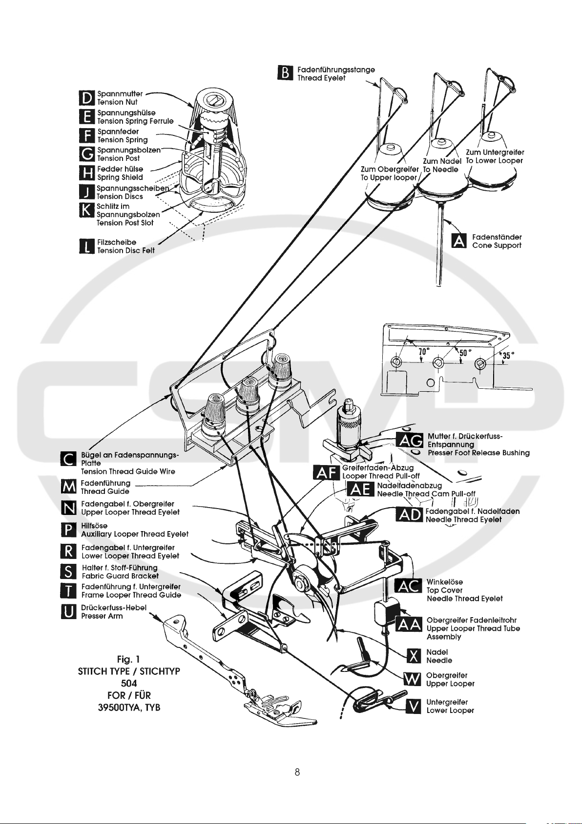
THREAD STAND
After thread comes from cones on cone support (A, Fig1) it
is brought up through back hole of thread eyelet bars (B),
then down through the front hole of thread eyelet bars.
Next it is threaded through the upper holes of tension thread
guide (C) from front to back and then through the lower holes
from back to front. The threads continue between tension
discs (J), through tension post slot (K) in tension post (G)
and on through front thread (M).
Quite la presión del pie prensatela girando el manguito (AG,
Fig. 1) hacia la izquierda. Gire el brazo del pie prensatela
(U) hacia la izquierda. Gire el volante en dirección de
operación hasta que la aguja se encuentre en su punto muerto
inferior. Suelte la tuerca que fija la aguja con la llave
hexagonal No. 21338AU que viene con los accesorios,
girándola aproximadamente ¼“ hacia la izquierda. Siga
girando el volante hasta que la aguja se encuentre en su
punto muerto superior y quite la aguja.
En esta posición elevada de la barra de la aguja se inserta la
aguja nueva hasta que el cabo toque el pasador tope.
Mantenga con la mano izquierda la aguja en esta posición,
gire el volante hasta que la aguja llegue a su punto muerto
inferior y apriete la tuerca que fija la aguja otra vez.
Regrese el brazo del pie prensatela (U, Fig. 1) a su posición
normal y gire el manguito (AG) hacia la derecha.
PORTA CONOS
Se enhebra el hilo desde los conos en los platos (A, Fig1)
desde abajo hacia arriba a trabes del ojete trasero en la barra
guía hilo (B) y después desde arriba hacia abajo a trabes del
ojete delantero.
Después se enhebra el hilo a través del ojete superior en la
guía de tensión (C) desde adelante hacia atrás y
posteriormente a través del ojete inferior desde atrás hacia
delante. Los hilos pasan entre los discos de tensión (J) a
través de la ranura (K) en el poste de tensión (G) y siguen
por la guía de hilo delantera (M).
THREADING
Only parts involved in threading are shown in the threading
diagram (Fig. 1).
Parts are placed in their relative positions for clarity.
It will simplify threading to follow the recomended sequence
of threading lower looper first, upper looper second and needle
third.
Before beginning to thread, swing cloth plate open, turn
handwheel in operating direction until needle (X) is in high
position, release pressure on presser foot by turning presser
foot release bushing (AG), and swing presser arm (U) out of
position.
Be sure the threads, as they come from the tension thread
guide (C), are between the tension discs (J) and in diagonal
slots (K) in tension posts (G). The tension posts should be
positioned so the tension post slot will be at the approximate
angle for the different threads as indicated in Fig. 1.
ENHEBRADO
La ilustración para enhebrar (Fig. 1) demuestra solamente
las piezas por las cuales pasa el hilo.
Para un mejor entendimiento se muestran esas piezas
esquemáticamente.
Se facilita el proceso de enhebrar cuando se proceda con la
maquina 39500TYA de la siguiente manera: primero el looper
inferior, segundo el looper superior y tercero la aguja.
Antes de enhebrar se gira la tapa en que reposa la tela hacia
la izquierda, se gira el volante en sentido de operación hasta
que la aguja (X) se encuentre en su punto muerto superior,
la presión del pie prensatela se quita girando el manguito
(AG) hacia la izquierda y se gira el brazo del pie prensatela
(U) hacia la izquierda.
Debería fijarse que los hilos que vienen desde la guía de
tensión (C), se encuentren entre los discos de tensión (J) y
pasen por la ranura en el poste de tensión (G). Los postes
de tensión deberían ser ajustados para que las ranuras en
los postes tengan aproximadamente el mismo ángulo como
se demuestra en la Fig. 1.
9
TO THREAD LOWER LOOPER
ENHEBRAR EL LOOPER INFERIOR
Thread lower looper thread through the right eyelet of front
thread guide (M, Fig. 1).
Double end of thread and lead it through both eyes of lower
looper thread eyelet (R) from right to left.
NOTE: Thread must pass in front of looper thread pull-off
(AF). Lead thread behind fabric guard (S) and through eyelet
hole of frame looper thread guide (T). Turn handwheel in
operating direction until heel of lower looper (V) is all the
way to the left; then thread through both eyes from left to
right. Left eye of lower looper can be threaded easily if
tweezers are in left hand.
TO THREAD UPPER LOOPER
Thread lower looper thread through the left eyelet of front
thread guide (M, Fig. 1).
Turn handwheel until point of upper looper (W, Fig. 1) is all
the way left. Lead thread through auxiliary looper thread eyelet
(P) from back to front, then through both eyes of upper looper
thread eyelet (N) from left to right.
NOTE: Thread must pass in front of looper thread pull-off
(AF). After pulling up upper looper thread tube assembly (AA),
lead thread under neck of top cover casting and down through
thread tube assembly (AA). Pull thread out bottom of tube;
push tube down, then insert thread through upper looper eye
from back to front.
Enhebre el hilo del looper inferior a través del ojete derecho en la
guía del hilo delantera (M, Fig. 1).
Tome el final del hilo doblado y enhébrelo de derecha a izquierda
a través de los ojetes en la horquilla inferior del hilo (R).
NOTA: El hilo debe estar encima del alimentador de hilo (AF).
Pase el hilo detrás del guarda tela (S) y a través del ojete del
guía hilo (T) del looper inferior. Gire el volante en sentido de
operación hasta que el looper inferior (V) se encuentre en su
posición a la extrema izquierda y enhebre los dos ojos del looper
desde la izquierda hacia la derecha. El ojo izquierdo del looper
inferior se enhebra más fácil, agarrando la pinza con la mano
izquierda.
ENHEBRAR EL LOOPER SUPERIOR
Enhebre el hilo del looper superior a través del ojete izquierdo en
la guía del hilo delantera (M, Fig. 1).
Gire el volante hasta que la punta del looper superior (W, Fig. 1)
se encuentre en su posición a la extrema izquierda. Enhebre el
hilo desde atrás hacia delante a través de la guía adicional (P) y
después desde la izquierda hacia la derecha a través de los dos
ojetes en la horquilla del looper superior (N).
NOTA: El hilo debe estar encima del alimentador de hilo (AF).
Hale el tubito (AA) que guía el hilo hacia arriba y i.e. el hilo debajo
del cuello en la tapa de la maquina hacia el tubito (AA) y a través
del tubito hacia abajo. Hale el hilo fuera del tubito, empuje el
tubito otra vez hacia abajo y enhebre el ojo del looper superior
desde adelante hacia atrás.
CAUTION: Be sure upper looper thread is under lower
looper thread when passing from tube assembly to upper
looper eye.
TO THREAD THE NEEDLE
Thread needle thread through the middle eyelet of front thread
guide (M, Fig. 1). Turn handwheel in operating direction until
needle (X) is at its highest position. Insert needle thread from
right to left, through both eyes of needle thread eyelet (AD),
under neck of top cover casting; then down through hole in
top cover needle thread eyelet (AC). Thread needle from the
front.
THREAD TENSION
The amount of tension on needle and looper threads is
regulated by the tension nuts (D, Fig. 1). Tension on threads
should be only enough to secure proper stitch formation.
PRECAUCION: El hilo del looper superior tiene que pasar en su
recorrido desde el tubito guía hilo hacia el ojo del looper debajo
del hilo del looper inferior.
ENHEBRAR LA AGUJA
Enhebre el hilo de la aguja a través del ojete de en medio en
la guía del hilo delantera (M, Fig. 1). Gire el volante en sentido
de operación hasta que la aguja (X) se encuentre en su punto
muerto superior. Enhebre el hilo desde la derecha hacia la
izquierda por los dos ojetes en la horquilla de hilo (AD) debajo
del cuello en la tapa de la maquina, después desde arriba
hacia abajo por el ojete en el guía hilo (AC) en la tapa de la
maquina y finalmente desde atrás hacia delante por el ojo
de la aguja.
TENSION DE LOS HILOS
Las tensiones de los hilos de la aguja y de los looper se ajustan
con la tuerca del ajuste de la tensión (D, Fig. 1). La tensión ebria
ser solamente tan fuerte para que se forma una puntada correcta.
10
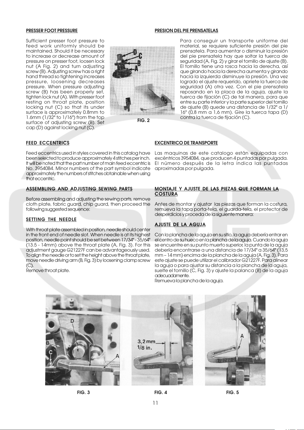
PRESSER FOOT PRESSURE
PRESION DEL PIE PRENSATELAS
Sufficient presser foot pressure to
feed work uniformly should be
maintained. Should it be necessary
to increase or decrease amount of
pressure on presser foot, loosen lock
nut (A Fig. 2) and turn adjusting
screw (B). Adjusting screw has a right
hand thread so tightening increases
pressure, loosening decreases
pressure. When pressure adjusting
screw (B) has been properly set,
tighten lock nut (A). With presser foot
resting on throat plate, position
locking nut (C) so that its under
surface is approximately 0.8mm to
1.6mm (1/32" to 1/16") from the top
surface of adjusting screw (B). Set
cap (D) against locking nut (C).
FEED ECCENTRICS
Feed eccentrics used in styles covered in this catalog have
been selected to produce approximately 4 stitches per inch.
It will be noted that the part number of main feed eccentric is
No. 39540B4. Minor numbers of the part symbol indicate
approximately the numbers of stitches obtainable when using
that eccentric.
ASSEMBLING AND ADJUSTING SEWING PARTS
Before assembling and adjusting the sewing parts, remove
cloth plate, fabric guard, chip guard, then proceed the
following suggested sequence:
SETTING THE NEEDLE
With throat plate assembled in position, needle should center
in the front end of needle slot. When needle is at its highest
position, needle point should be set between 17/34" - 35/64"
(13.5 - 14mm) above the throat plate (A, Fig. 3). For this
adjustment gauge G21227F can be advantageously used.
To align the needle or to set the height above the throat plate,
move needle driving arm (B, Fig. 3) by loosening clamp screw
(C).
Remove throat plate.
FIG. 2
Para conseguir un transporte uniforme del
material, se requiere suficiente presión del pie
prensatela. Para aumentar o disminuir la presión
del pie prensatela hay que soltar la tuerca de
seguridad (A, Fig. 2) y girar el tornillo de ajuste (B).
El tornillo tiene una rosca hacia la derecha, así
que girando hacia la derecha aumenta y girando
hacia la izquierda disminuye la presión. Una vez
logrado el ajuste requerido, apriete la tuerca de
seguridad (A) otra vez. Con el pie prensatela
reposando en la placa de la aguja, ajuste la
tuerca de fijación (C) de tal manera, para que
entre su parte inferior y la parte superior del tornillo
de ajuste (B) quede una distancia de 1/32" a 1/
16" (0,8 mm a 1,6 mm). Gire la tuerca tapa (D)
contra la tuerca de fijación (C).
EXCENTRICO DE TRANSPORTE
Las maquinas de este catalogo están equipadas con
excéntricos 39540B4, que producen 4 puntadas por pulgada.
El número después de la letra indica las puntadas
aproximadas por pulgada.
MONTAJE Y AJUSTE DE LAS PIEZAS QUE FORMAN LA
COSTURA
Antes de montar y ajustar las piezas que forman la costura,
remueva la tapa porta-tela, el guarda-tela, el protector de
desperdicios y proceda de la siguiente manera:
AJUSTE DE LA AGUJA
Con la plancha de la aguja en su sitio, la aguja debería entrar en
el centro de su hueco en la plancha de la aguja. Cuando la aguja
se encuentre en su punto muerto superior, la punta de la aguja
debería encontrarse a una distancia de 17/34" a 35/64" (13,5
mm – 14 mm) encima de la plancha de la aguja (A, Fig. 3). Para
este ajuste se puede utilizar el calibrador G21227F. Para alinear
la aguja o para ajustar su distancia a la plancha de la aguja,
suelte el tornillo (C, Fig. 3) y ajuste la palanca (B) de la aguja
adecuadamente.
Remueva la plancha de la aguja.
FIG. 3 FIG. 4 FIG. 5
11
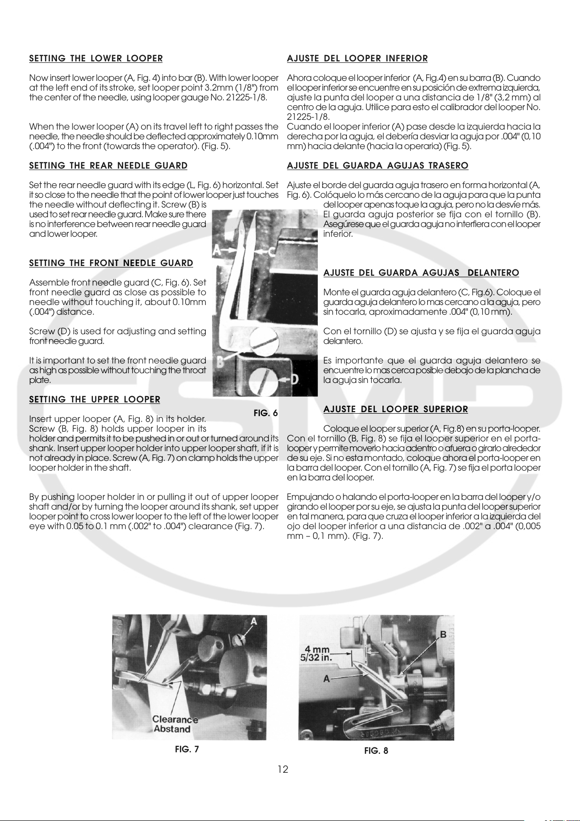
SETTING THE LOWER LOOPER
AJUSTE DEL LOOPER INFERIOR
Now insert lower looper (A, Fig. 4) into bar (B). With lower looper
at the left end of its stroke, set looper point 3.2mm (1/8") from
the center of the needle, using looper gauge No. 21225-1/8.
When the lower looper (A) on its travel left to right passes the
needle, the needle should be deflected approximately 0.10mm
(.004") to the front (towards the operator). (Fig. 5).
SETTING THE REAR NEEDLE GUARD
Set the rear needle guard with its edge (L, Fig. 6) horizontal. Set
it so close to the needle that the point of lower looper just touches
the needle without deflecting it. Screw (B) is
used to set rear needle guard. Make sure there
is no interference between rear needle guard
and lower looper.
SETTING THE FRONT NEEDLE GUARD
Assemble front needle guard (C, Fig. 6). Set
front needle guard as close as possible to
needle without touching it, about 0.10mm
(.004") distance.
Screw (D) is used for adjusting and setting
front needle guard.
It is important to set the front needle guard
as high as possible without touching the throat
plate.
Ahora coloque el looper inferior (A, Fig.4) en su barra (B). Cuando
el looper inferior se encuentre en su posición de extrema izquierda,
ajuste la punta del looper a una distancia de 1/8" (3,2 mm) al
centro de la aguja. Utilice para esto el calibrador del looper No.
21225-1/8.
Cuando el looper inferior (A) pase desde la izquierda hacia la
derecha por la aguja, el debería desviar la aguja por .004" (0,10
mm) hacia delante (hacia la operaria) (Fig. 5).
AJUSTE DEL GUARDA AGUJAS TRASERO
Ajuste el borde del guarda aguja trasero en forma horizontal (A,
Fig. 6). Colóquelo lo más cercano de la aguja para que la punta
del looper apenas toque la aguja, pero no la desvíe más.
El guarda aguja posterior se fija con el tornillo (B).
Asegúrese que el guarda aguja no interfiera con el looper
inferior.
AJUSTE DEL GUARDA AGUJAS DELANTERO
Monte el guarda aguja delantero (C, Fig.6). Coloque el
guarda aguja delantero lo mas cercano a la aguja, pero
sin tocarla, aproximadamente .004" (0,10 mm).
Con el tornillo (D) se ajusta y se fija el guarda aguja
delantero.
Es importante que el guarda aguja delantero se
encuentre lo mas cerca posible debajo de la plancha de
la aguja sin tocarla.
SETTING THE UPPER LOOPER
Insert upper looper (A, Fig. 8) in its holder.
Screw (B, Fig. 8) holds upper looper in its
holder and permits it to be pushed in or out or turned around its
shank. Insert upper looper holder into upper looper shaft, if it is
not already in place. Screw (A, Fig. 7) on clamp holds the upper
looper holder in the shaft.
By pushing looper holder in or pulling it out of upper looper
shaft and/or by turning the looper around its shank, set upper
looper point to cross lower looper to the left of the lower looper
eye with 0.05 to 0.1 mm (.002" to .004") clearance (Fig. 7).
FIG. 6
AJUSTE DEL LOOPER SUPERIOR
Coloque el looper superior (A, Fig.8) en su porta-looper.
Con el tornillo (B, Fig. 8) se fija el looper superior en el porta-
looper y permite moverlo hacia adentro o afuera o girarlo alrededor
de su eje. Si no esta montado, coloque ahora el porta-looper en
la barra del looper. Con el tornillo (A, Fig. 7) se fija el porta looper
en la barra del looper.
Empujando o halando el porta-looper en la barra del looper y/o
girando el looper por su eje, se ajusta la punta del looper superior
en tal manera, para que cruza el looper inferior a la izquierda del
ojo del looper inferior a una distancia de .002" a .004" (0,005
mm – 0,1 mm). (Fig. 7).
FIG. 7
FIG. 8
12
 Loading...