

Union Special PT0303 GR Parts Book
CATALOG NO.
PT0303-GR
First Edition
STYLES
56100MB
56100PB
56100TB
INSTRUCTIONS AND
ILLUSTRATED PARTS LIST
04-03-09
CLASS 56100 - ADVANCED SERIES,
BAG SEAMING MACHINES
CATALOG NO. PT0303-GR
ADJUSTNG INSTRUCTIONS AND
ILLUSTRATED PARTS LIST FOR
CLASS 56100
ADVANCED SERIES
BAG SEAMING MACHINE
STYLE
56100MB
56100PB
56100TB
First Edition
© 2006
PRINTED 2006 IN USA
INFORMATION SUBJECT TO
CHANGE WITHOUT NOTICE
© Union Special Corporation
ALL Rights Reserved in All
Countries
2
IDENTIFICATION OF MACHINES
Each UNION SPECIAL machine carries a Style number, which on this Class machine is stamped into the
style plate affixed to the right front of machine.
The serial number is stamped in the casting at the right rear base of machine.
Reference to directions, such as right, left, front or rear, are given relative to the operator’s position
while seated at the machine.Operating direction of the handwheel is counterclockwise, as viewed from
the right end of machine.
CLASS DESCRIPTION
Advanced high speed, single needle, flat bed machine with needle bearing assembly for left mainshaft
bushing. High throw, needle bearing needle bar drive, light weight presser bar and needle bar driving
mechanism, enclosed automatic lubricating system, filtered oil return pumps for head and base, lateral
looper travel. Maximum work space to right of needle bar, 8 1/4 inches (209.6mm).
MACHINE STYLE
56100MB Typical application - For seaming medium and large size cotton, light and medium weight
burlap bags. Stitch range 3 1/2 to 7. Seam specification 401-SSa-1. Maxmum recommended
speed 6000 R.P.M. sewing at 3 1/2 to 5 S.P.I. and 6500 R.P.M. sewing at more than 5 S.P.I.
Recommended speed for machines operating on a duty cycle of 50% or more is 10% less
than maximum.
56100PB Typical application - For seaming medium to large bags. Ultra High Throw, Stitch range 3 1/2
to 7. Seam specification 401-SSa-1. Maxmum recommended speed 6000 R.P.M.
56100TB Typical application - For hemming bag openings and for producing side and bottom double
turned-in seams on woven polypropylene bags. Stitch range 3 1/2 to 7. Seam specification
401-EFb-1 or 401-SSp-1. Maxmum recommended speed 6000 R.P.M.
NEEDLES
Each needle has both a type and size number.The type number denotes the kind of shank, point, length,
groove, finish and other details. The size number, stamped on the needle shank, denotes largest diam-
eter of blade, measured midway between shank and eye. Collectively, type and size number represent
the complete symbol, which is given on the label of all needles packaged and sold by UNION SPECIAL.
Recommended needle for Style 56100MB, PB, and TB is Type 144GS. It has a round shank, round point,
No. 2 bag length, double groove, spotted, short point, chromium plated, and is available in sizes -
200/080, 230/090, 250/100.
Selection of proper needle size is determined by size of thread used. Thread should pass freely through
needle eye in order to produce a good stitch formation.
To have needle orders promptly arid accurately filled, an empty package,a sample needle, or the type
and size number should be forwarded. Use description on label. A complete order would read: “1000
Needles, Type 144GS, Size 200/080”.
3
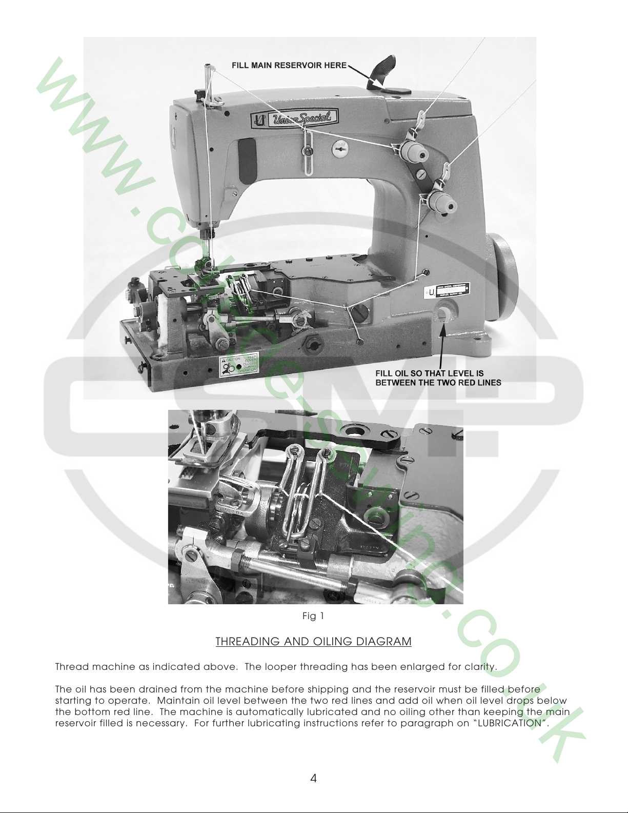
Fig 1
THREADING AND OILING DIAGRAM
Thread machine as indicated above. The looper threading has been enlarged for clarity.
The oil has been drained from the machine before shipping and the reservoir must be filled before
starting to operate. Maintain oil level between the two red lines and add oil when oil level drops below
the bottom red line. The machine is automatically lubricated and no oiling other than keeping the main
reservoir filled is necessary. For further lubricating instructions refer to paragraph on “LUBRICATION”.
4
SAFETY RULES
THIS SAFETY SYMBOL INDICATES YOUR PERSONAL SAFETY IS INVOLVED.
TO PREVENT PERSONAL INJURY:
- All power sources to the machine MUST be TURNED OFF before threading, oiling, adjusting or replacing
parts.
- Wear safety glasses.
- All shields and guards MUST be in position before operating machine.
- DO NOT tamper with safety shields, guards, etc., while machine is in operation.
Use a straight mineral oil with a Saybolt viscosity of 90 to 125 seconds at 100 degrees F. This is equivalent
to UNION SPECIAL Specification No. 175.
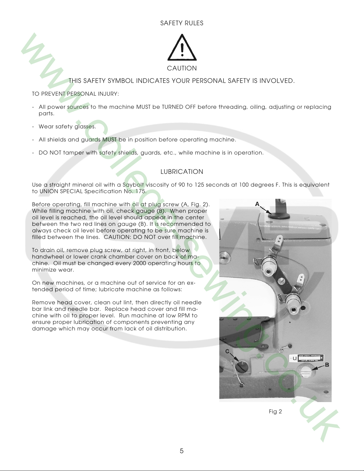
Before operating, fill machine with oil at plug screw (A, Fig. 2).
While filling machine with oil, check gauge (B). When proper
oil level is reached, the oil level should appear in the center
between the two red lines on gauge (B). It is recommended to
always check oil level before operating to be sure machine is
filled between the lines. CAUTION: DO NOT over fill machine.
CAUTION
LUBRICATION
To drain oil, remove plug screw, at right, in front, below
handwheel or lower crank chamber cover on back of ma-
chine. Oil must be changed every 2000 operating hours to
minimize wear.
On new machines, or a machine out of service for an ex-
tended period of time; lubricate machine as follows:
Remove head cover, clean out lint, then directly oil needle
bar link and needle bar. Replace head cover and fill ma-
chine with oil to proper level. Run machine at low RPM to
ensure proper lubrication of components preventing any
damage which may occur from lack of oil distribution.
Fig 2
5
SYNCHRONIZING LOOPER AND NEEDLE MOTIONS
Synchronization is the most important adjustment
involving the needle and looper motion relation,
because it maintains the needle-looper relation at
both the needle loop taking time, as well as when
the needle enters the looper triangle. This adjustment
is best made using synchronization gauge set TT34.
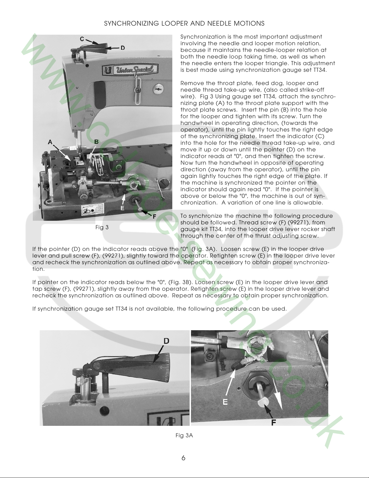
Remove the throat plate, feed dog, looper and
needle thread take-up wire, (also called strike-off
wire). Fig 3 Using gauge set TT34, attach the synchro-
nizing plate (A) to the throat plate support with the
throat plate screws. Insert the pin (B) into the hole
for the looper and tighten with its screw. Turn the
handwheel in operating direction, (towards the
operator), until the pin lightly touches the right edge
of the synchronizing plate. Insert the indicator (C)
into the hole for the needle thread take-up wire, and
move it up or down until the pointer (D) on the
indicator reads at "0", and then tighten the screw.
Now turn the handwheel in opposite of operating
direction (away from the operator), until the pin
again lightly touches the right edge of the plate. If
the machine is synchronized the pointer on the
indicator should again read "0". If the pointer is
above or below the "0", the machine is out of syn-
chronization. A variation of one line is allowable.
To synchronize the machine the following procedure
Fig 3
If the pointer (D) on the indicator reads above the "0" (Fig. 3A). Loosen screw (E) in the looper drive
lever and pull screw (F), (99271), slightly toward the operator. Retighten screw (E) in the looper drive lever
and recheck the synchronization as outlined above. Repeat as necessary to obtain proper synchroniza-
tion.
If pointer on the indicator reads below the "0", (Fig. 3B). Loosen screw (E) in the looper drive lever and
tap screw (F), (99271), slightly away from the operator. Retighten screw (E) in the looper drive lever and
recheck the synchronization as outlined above. Repeat as necessary to obtain proper synchronization.
If synchronization gauge set TT34 is not available, the following procedure can be used.
should be followed. Thread screw (F) (99271), from
gauge kit TT34, into the looper drive lever rocker shaft
through the center of the thrust adjusting screw.
Fig 3A
6
SYNCHRONIZING LOOPER AND NEEDLE MOTIONS (CONTINUED)
Fig 3B
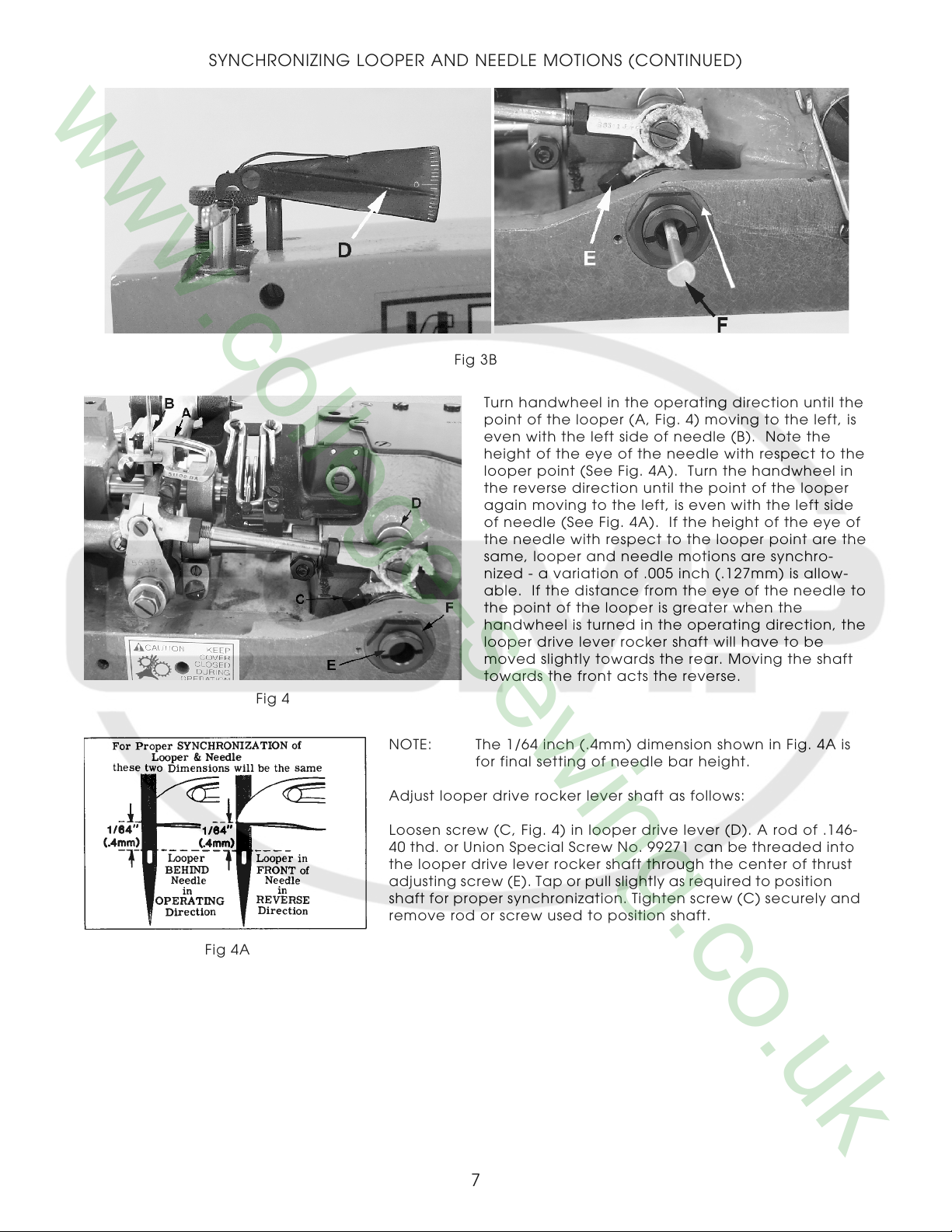
Turn handwheel in the operating direction until the
point of the looper (A, Fig. 4) moving to the left, is
even with the left side of needle (B). Note the
height of the eye of the needle with respect to the
looper point (See Fig. 4A). Turn the handwheel in
the reverse direction until the point of the looper
again moving to the left, is even with the left side
of needle (See Fig. 4A). If the height of the eye of
the needle with respect to the looper point are the
same, looper and needle motions are synchro-
nized - a variation of .005 inch (.127mm) is allow-
able. If the distance from the eye of the needle to
the point of the looper is greater when the
handwheel is turned in the operating direction, the
looper drive lever rocker shaft will have to be
moved slightly towards the rear. Moving the shaft
towards the front acts the reverse.
Fig 4
Fig 4A
NOTE: The 1/64 inch (.4mm) dimension shown in Fig. 4A is
for final setting of needle bar height.
Adjust looper drive rocker lever shaft as follows:
Loosen screw (C, Fig. 4) in looper drive lever (D). A rod of .146-
40 thd. or Union Special Screw No. 99271 can be threaded into
the looper drive lever rocker shaft through the center of thrust
adjusting screw (E). Tap or pull slightly as required to position
shaft for proper synchronization. Tighten screw (C) securely and
remove rod or screw used to position shaft.
7
SYNCHRONIZING LOOPER AND NEEDLE MOTIONS (CONTINUED)
Loosen lock nut (F) and TORQUE thrust adjjusting
screw (E) to 6 in. lbs. (7cm/kg); re-tighten lock nut
(F) securely.
Fig 5
LOOPER AND LOOPER NEEDLE GUARD SETTINGS
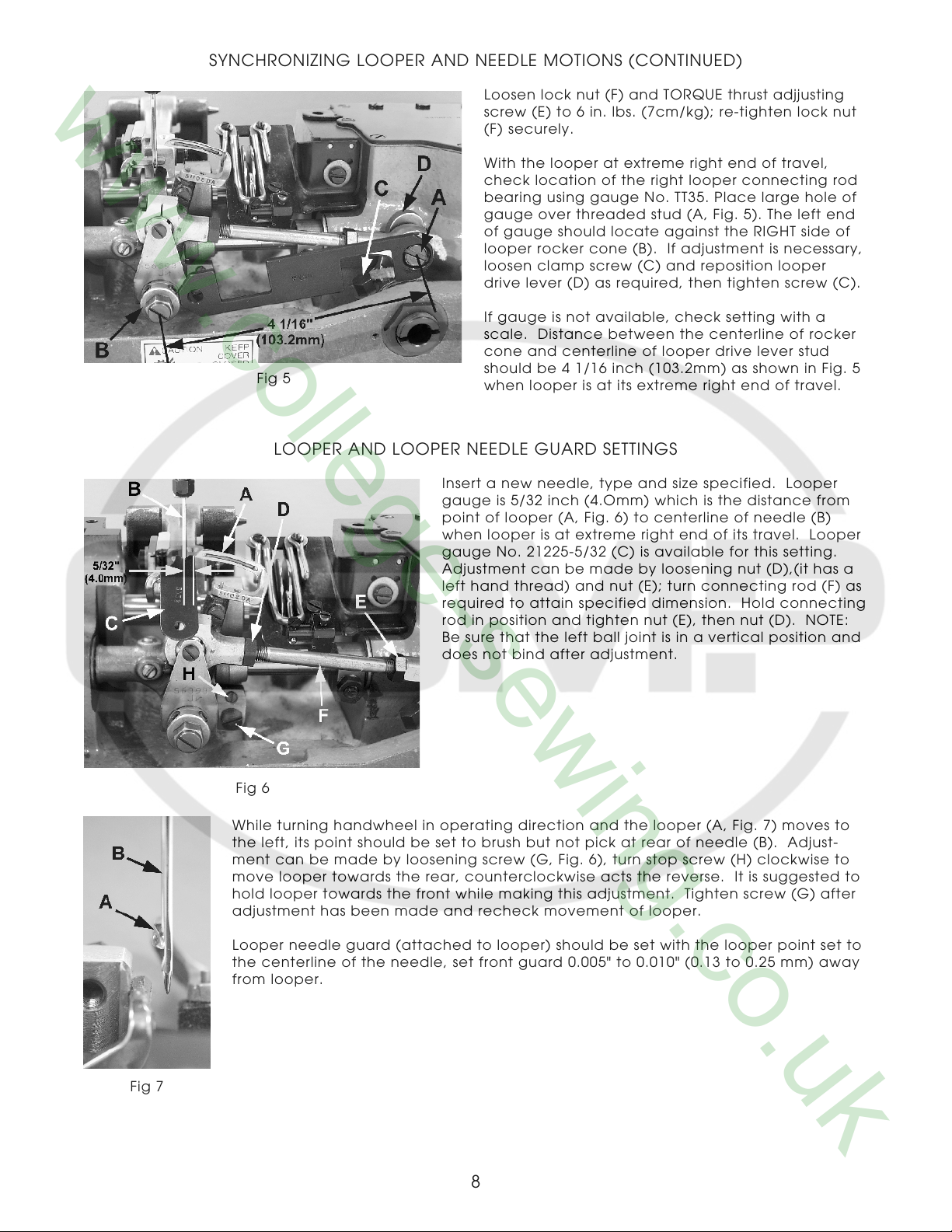
With the looper at extreme right end of travel,
check location of the right looper connecting rod
bearing using gauge No. TT35. Place large hole of
gauge over threaded stud (A, Fig. 5). The left end
of gauge should locate against the RIGHT side of
looper rocker cone (B). If adjustment is necessary,
loosen clamp screw (C) and reposition looper
drive lever (D) as required, then tighten screw (C).
If gauge is not available, check setting with a
scale. Distance between the centerline of rocker
cone and centerline of looper drive lever stud
should be 4 1/16 inch (103.2mm) as shown in Fig. 5
when looper is at its extreme right end of travel.
Insert a new needle, type and size specified. Looper
gauge is 5/32 inch (4.Omm) which is the distance from
point of looper (A, Fig. 6) to centerline of needle (B)
when looper is at extreme right end of its travel. Looper
gauge No. 21225-5/32 (C) is available for this setting.
Adjustment can be made by loosening nut (D),(it has a
left hand thread) and nut (E); turn connecting rod (F) as
required to attain specified dimension. Hold connecting
rod in position and tighten nut (E), then nut (D). NOTE:
Be sure that the left ball joint is in a vertical position and
does not bind after adjustment.
Fig 7
Fig 6
While turning handwheel in operating direction and the looper (A, Fig. 7) moves to
the left, its point should be set to brush but not pick at rear of needle (B). Adjust-
ment can be made by loosening screw (G, Fig. 6), turn stop screw (H) clockwise to
move looper towards the rear, counterclockwise acts the reverse. It is suggested to
hold looper towards the front while making this adjustment. Tighten screw (G) after
adjustment has been made and recheck movement of looper.
Looper needle guard (attached to looper) should be set with the looper point set to
the centerline of the needle, set front guard 0.005" to 0.010" (0.13 to 0.25 mm) away
from looper.
8
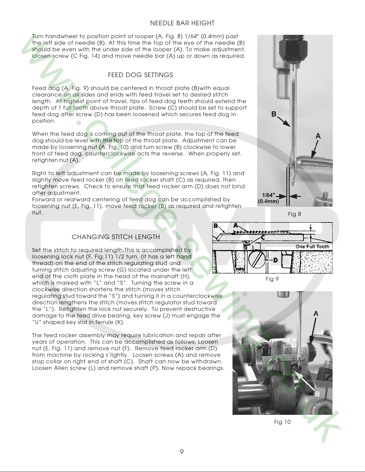
NEEDLE BAR HEIGHT
Turn handwheel to position point of looper (A, Fig. 8) 1/64" (0.4mm) past
the left side of needle (B). At this time the top of the eye of the needle (B)
should be even with the under side of the looper (A). To make adjustment,
loosen screw (C Fig. 14) and move needle bar (A) up or down as required.
FEED DOG SETTINGS
Feed dog (A, Fig. 9) should be centered in throat plate (B)with equal
clearance on all sides and ends with feed travel set to desired stitch
length. At highest point of travel, tips of feed dog teeth should extend the
depth of 1 full tooth above throat plate. Screw (C) should be set to support
feed dog after screw (D) has been loosened which secures feed dog in
position.
When the feed dog is coming out of the throat plate, the top of the feed
dog should be level with the top of the throat plate. Adjustment can be
made by loosening nut (A, Fig. 10) and turn screw (B) clockwise to lower
front of feed dog, counterclockwise acts the reverse. When properly set,
retighten nut (A).
Right to left adjustment can be made by loosening screws (A, Fig. 11) and
slightly move feed rocker (B) on feed rocker shaft (C) as required, then
retighten screws. Check to ensure that feed rocker arm (D) does not bind
after adjustment.
Forward or rearward centering of feed dog can be accomplished by
loosening nut (E, Fig. 11), move feed rocker (B) as required and retighten
nut.
Fig 8
CHANGING STITCH LENGTH
Set the stitch to required length.This is accomplished by
loosening lock nut (F, Fig.11) 1/2 turn, (it has a left hand
thread) on the end of the stitch regulating stud and
turning stitch adjusting screw (G) located under the left
end of the cloth plate in the head of the mainshaft (H),
which is marked with “L” and “S”. Turning the screw in a
clockwise direction shortens the stitch (moves stitch
regulating stud toward the “S”) and turning it in a counterclockwise
direction lengthens the stitch (moves stitch regulator stud toward
the “L”). Retighten the lock nut securely. To prevent destructive
damage to the feed drive bearing, key screw (J) must engage the
“U” shaped key slot in ferrule (K).
The feed rocker assembly may require lubrication and repair after
years of operation. This can be accomplished as follows: Loosen
nut (E, Fig. 11) and remove nut (F). Remove feed rocker arm (D)
from machine by rocking s’lightly. Loosen screws (A) and remove
stop collar on right end of shaft (C). Shaft can now be withdrawn.
Loosen Allen screw (L) and remove shaft (P), Now repack bearings.
Fig 9
Fig 10
9
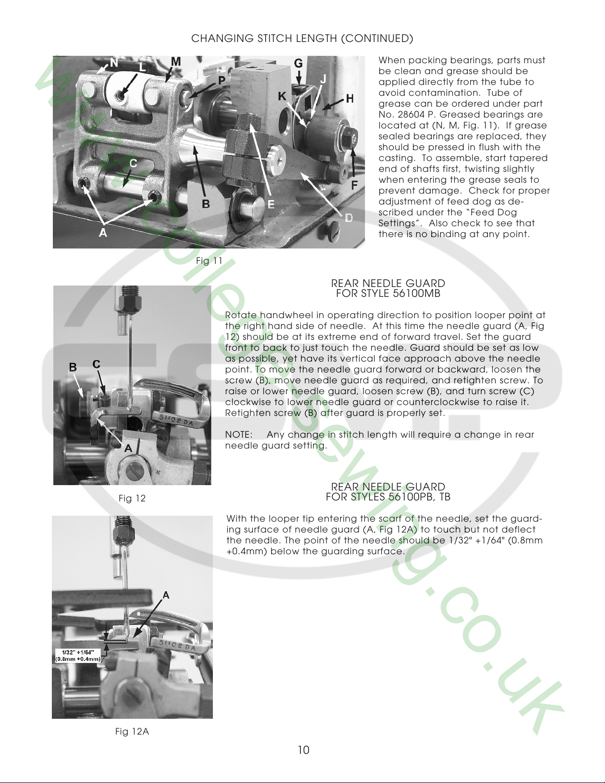
CHANGING STITCH LENGTH (CONTINUED)
When packing bearings, parts must
be clean and grease should be
applied directly from the tube to
avoid contamination. Tube of
Fig 11
REAR NEEDLE GUARD
FOR STYLE 56100MB
Rotate handwheel in operating direction to position looper point at
the right hand side of needle. At this time the needle guard (A, Fig
12) should be at its extreme end of forward travel. Set the guard
front to back to just touch the needle. Guard should be set as low
as possible, yet have its vertical face approach above the needle
point. To move the needle guard forward or backward, loosen the
screw (B), move needle guard as required, and retighten screw. To
raise or lower needle guard, loosen screw (B), and turn screw (C)
clockwise to lower needle guard or counterclockwise to raise it.
Retighten screw (B) after guard is properly set.
grease can be ordered under part
No. 28604 P. Greased bearings are
located at (N, M, Fig. 11). If grease
sealed bearings are replaced, they
should be pressed in flush with the
casting. To assemble, start tapered
end of shafts first, twisting slightly
when entering the grease seals to
prevent damage. Check for proper
adjustment of feed dog as de-
scribed under the “Feed Dog
Settings”. Also check to see that
there is no binding at any point.
Fig 12
NOTE: Any change in stitch length will require a change in rear
needle guard setting.
REAR NEEDLE GUARD
FOR STYLES 56100PB, TB
With the looper tip entering the scarf of the needle, set the guard-
ing surface of needle guard (A, Fig 12A) to touch but not deflect
the needle. The point of the needle should be 1/32" +1/64" (0.8mm
+0.4mm) below the guarding surface.
Fig 12A
10
THREADING
Draw looper and needle threads into the machine and start
operating on a piece of fabric. Refer to threading diagram
(Fig. 1) for manner of threading this machine.
Looper thread cast-off wire (A, Fig. 13) located on the take-
up shield (B) controls the amount of slack thread in the system
and can be moved to any position. It should be set laterally
so that it is midway between the two discs of take-up (C) and
the tip parallel with the discs.
It is usually set toward the take-up to almost the limit of its slot
so that it barely clears the highest point of the take-up. The
height and lateral adjustment of the retainer affects the
control of looper thread as looper moves to the left. Ordi-
narily it will be set in approximately a horizontal position.
More looper thread is given to the stitch when the retainer is
raised and set towards the take-up. However, if the retainer
is raised too high, the looper thread triangle may be wiped
under the blade of the looper, causing traingle skips or pulled
down stitches. This can be checked by observing the action
of the looper thread as the looper moves to the left.
Tension on the needle thread should be only sufficient to produce uniform
stitches on the under surface of the fabric. Tension on the looper thread
should be just sufficient to steady the thread.
LOOPER THREAD CAST-OFF WIRE
Fig 13
THREAD TENSIONS
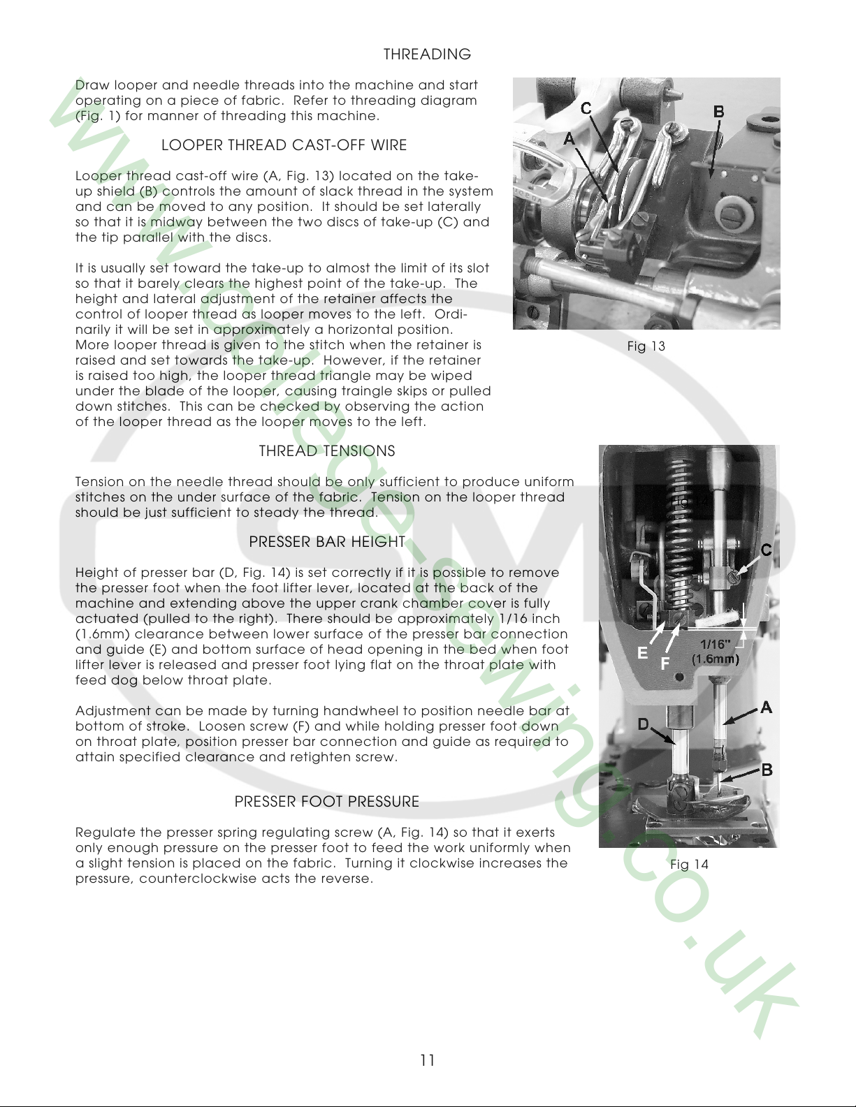
Fig 14
PRESSER BAR HEIGHT
Height of presser bar (D, Fig. 14) is set correctly if it is possible to remove
the presser foot when the foot lifter lever, located at the back of the
machine and extending above the upper crank chamber cover is fully
actuated (pulled to the right). There should be approximately 1/16 inch
(1.6mm) clearance between lower surface of the presser bar connection
and guide (E) and bottom surface of head opening in the bed when foot
lifter lever is released and presser foot lying flat on the throat plate with
feed dog below throat plate.
Adjustment can be made by turning handwheel to position needle bar at
bottom of stroke. Loosen screw (F) and while holding presser foot down
on throat plate, position presser bar connection and guide as required to
attain specified clearance and retighten screw.
PRESSER FOOT PRESSURE
Regulate the presser spring regulating screw (A, Fig. 14) so that it exerts
only enough pressure on the presser foot to feed the work uniformly when
a slight tension is placed on the fabric. Turning it clockwise increases the
pressure, counterclockwise acts the reverse.
Fig 14
11
 Loading...