

CATALOG NO.
31200AQ64Z6
PT0203
First Edition
STYLES
31200AQ64
ADJUSTING INSTRUCTIONS
AND ILLUSTRATED PARTS LIST
04-02-04
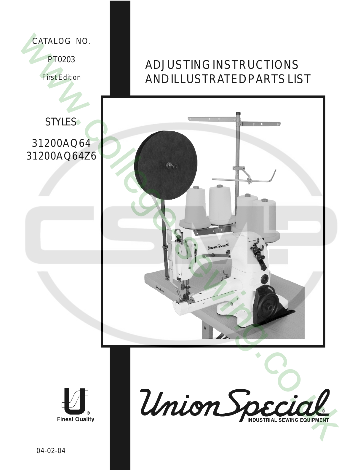
31200AQ64
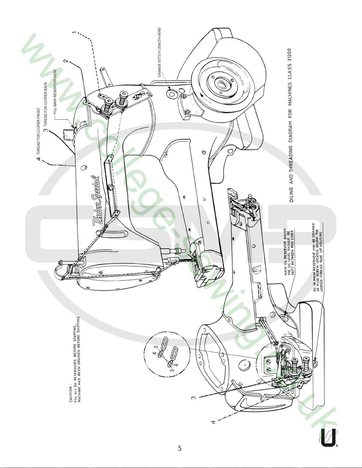
High Speed, Feed Up The Arm, Plain Feed, Two needle, two looper, Side Wheel Cylinder Bed Machine specifi-
cally designed for Taping Shoulders and Collar Seams on Knitwear.
DESCRIPTION OF MACHINE
31200AQ64Z6
NEEDLE TYPE:
SETTING THE NEEDLES:
SETTING OF THE NEEDLE BAR:
LOOPER ADJUSTMENT:
Equipped with top tape reel and Presser Foot with folder for a precut 3/4" (19mm) tape to finish 3/8" (9.5mm).
Seam Spec. 401SSag-3. 6.4mm (16ga) needle spacing only. 4500 R.P.M. Maximum speed.
Same as 31200AQ64 except without presser foot.
128 GJS: Short, double groove, struck groove, thin ball point, spotted, tapered blade reinforcement, chro-
mium plated - sizes 070 / 027, 075 / 029, 080 / 032, 090 / 036.
Before readjusting the machine insert two new needles type 128GJS as far as they will go into the needle bar
head. The long groove must show to the operator. Tighten set screws securely.
To set the needle bar for the correct needle space in line of feed use the assembled needle guard, as the
step of the needle guard is the same as the needle space. The needles should slightly touch the needle
guard. After the setting, check that the needles are in the center of the stitch holes.
Insert the rear looper in the rear looper holder and be sure that the screw rests on the looper flat. The looper
gauge is 13/64"(5.16mm) measured from the center line of the left needle to the looper point with the looper
at the extreme left of its travel. Use of looper gauge 21225 - 13/64" is of advantage. For adjusting the looper
gauge loosen the clamp screw of the rear looper holder and move holder on the looper shaft to obtain
proper setting.
NEEDLE BAR HEIGHT:
Set the needle bar so that the tops of the needle eyes are about 5/64"(2mm) below the looper points when
the points are flush with the right side of the needles on their travel to the right. Watch that the needle bar
does not turn during this adjustment.
LOOPER TO NEEDLE SET:
After setting the needle bar to the correct height, set the loopers front to back to touch but not deflect the
needles at loop taking time
2
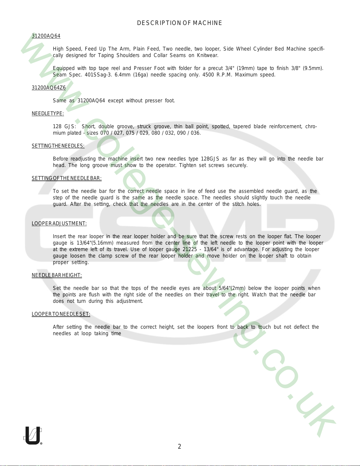
LOOPER AVOID MOTION:
The amount of looper avoid has been set at the factory to approximately .080"
(2.0mm). If it becomes necessary to adjust the amount of avoid it is recom-
mended as a starting point, to have the points of the decending needles
contact the lower 1/3 of the back of the looper blade.
NEEDLE GUARD:
Set the rear guard horizontally so that it barely contacts the needles when at its extreme forward position. It
should be set vertically as low as possible, yet have its guarding surface in contact with the needle until the
points of the loopers moving to the right are even with the right side of needles.
NOTE: Any time you change stitch length you must reset the guard.
After changing the looper avoid motion check the adjustment with respect to
the needle.
After setting the rear looper insert the front looper. The adjustment of both
loopers is the same.
To adjust the looper avoid motion remove cover plate No.31182N
at the rear of the machine. Loosen the nut with wrench No. 21388
(see sketch). To increase the avoid motion the connection link must
be moved downwards and to reduce it upwards. Tighten the nut
and replace the cover plate No. 31182N with the gasket.
FEED DOG SETTING:
The feed dog height is set correctly when the tips of the teeth project ±3/64"(1.2mm) above the throat plate
at its highest position. The height adjustment is made by loosening the set screws No. 22894W and turning the
eccentric stud No. 31139A. After this adjustment tighten set screw. At maximum stitch length adjust feed dog
to have equal clearance at both ends of the slots. Loosen screw on feed dog and move front to back to
obtain proper setting.
PRESSER FOOT:
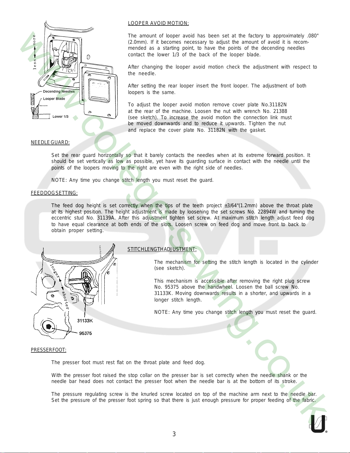
STITCH LENGTH ADJUSTMENT:
The mechanism for setting the stitch length is located in the cylinder
(see sketch).
This mechanism is accessible after removing the right plug screw
No. 95375 above the handwheel. Loosen the ball screw No.
31133K. Moving downwards results in a shorter, and upwards in a
longer stitch length.
NOTE: Any time you change stitch length you must reset the guard.
The presser foot must rest flat on the throat plate and feed dog.
With the presser foot raised the stop collar on the presser bar is set correctly when the needle shank or the
needle bar head does not contact the presser foot when the needle bar is at the bottom of its stroke.
The pressure regulating screw is the knurled screw located on top of the machine arm next to the needle bar.
Set the pressure of the presser foot spring so that there is just enough pressure for proper feeding of the fabric.
3
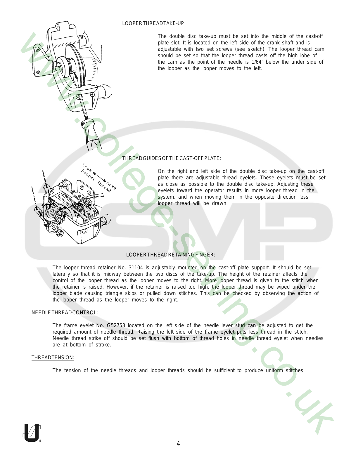
LOOPER THREAD TAKE-UP:
The double disc take-up must be set into the middle of the cast-off
plate slot. It is located on the left side of the crank shaft and is
adjustable with two set screws (see sketch). The looper thread cam
should be set so that the looper thread casts off the high lobe of
THREAD GUIDES OF THE CAST-OFF PLATE:
the cam as the point of the needle is 1/64" below the under side of
the looper as the looper moves to the left.
On the right and left side of the double disc take-up on the cast-off
plate there are adjustable thread eyelets. These eyelets must be set
as close as possible to the double disc take-up. Adjusting these
eyelets toward the operator results in more looper thread in the
system, and when moving them in the opposite direction less
looper thread will be drawn.
The looper thread retainer No. 31104 is adjustably mounted on the cast-off plate support. It should be set
laterally so that it is midway between the two discs of the take-up. The height of the retainer affects the
control of the looper thread as the looper moves to the right. More looper thread is given to the stitch when
the retainer is raised. However, if the retainer is raised too high, the looper thread may be wiped under the
looper blade causing triangle skips or pulled down stitches. This can be checked by observing the action of
the looper thread as the looper moves to the right.
NEEDLE THREAD CONTROL:
The frame eyelet No. G52758 located on the left side of the needle lever stud can be adjusted to get the
required amount of needle thread. Raising the left side of the frame eyelet puts less thread in the stitch.
Needle thread strike off should be set flush with bottom of thread holes in needle thread eyelet when needles
are at bottom of stroke.
THREAD TENSION:
The tension of the needle threads and looper threads should be sufficient to produce uniform stitches.
LOOPER THREAD RETAINING FINGER:
4
5
6
Ref.
No.
Part No.
1
2
3
4
5
6
7
8
9
10
11
12
13
14
15
16
17
18
19
20
21
22
23
24
25
26
27
28
29
30
31
32
33
34
35
36
37
38
39
719
34354
31194A
87U
43443Q
666-214
31194B
80262I
31154
31155
31194
51294Z
21212
53394Q
666-201
666-209
22729B
22729AB
21657X
31142C
999-1
999-35
31190B
31140A
31140
999-36
31140B
31291
15430L
22569B
660-202
31121A
22894G
31175C
G56375
22581
61321J
61321L
22574
Description
Screw ................................................................................................................
Needle Bar Bushing, Upper ..............................................................................
Oil Tube Clamp .................................................................................................................
Screw ................................................................................................................
Nut ......................................................................................................................................
Felt Lint Filter .......................................................................................................................
Felt ....................................................................................................................
Bushing For Presser Guide Bar ..........................................................................................
Needle Bar Bushing, Lower ..............................................................................
Bushing For Presser Bar ......................................................................................
Oil Siphon Tube .................................................................................................
Oil Tube Connection ........................................................................................
Oil Siphon Connection Locking Ring ...............................................................
Oil siphon Assembly ..........................................................................................
Felt Plug ......................................................................................................
Siphon Cup Disc, Felt .................................................................................
Screw .........................................................................................................
Screw ................................................................................................................
Bushing .............................................................................................................
Bushing .............................................................................................................
Gasket ..............................................................................................................
Gasket ..............................................................................................................
Crankshaft Bushing ..........................................................................................
Bushing For Looper Bar .....................................................................................
Bushing For Looper Bar .....................................................................................
Gasket ..............................................................................................................
Bushing For Looper Bar .....................................................................................
Crankshaft Bushing Housing, Including Bushing ..............................................
Felt ....................................................................................................................
Screw ................................................................................................................
"O"Ring ..............................................................................................................
Pulley ................................................................................................................
Screw ................................................................................................................
Cloth Guard ......................................................................................................
Belt Guard ........................................................................................................
Screw ................................................................................................................
Handwheel .......................................................................................................
Washer ..............................................................................................................
Screw ................................................................................................................
Amt.
Req.
2
1
1
1
1
1
1
1
1
1
1
1
1
1
1
1
1
1
1
1
1
1
1
1
1
1
1
1
1
4
1
1
2
1
1
2
1
1
3
7
8
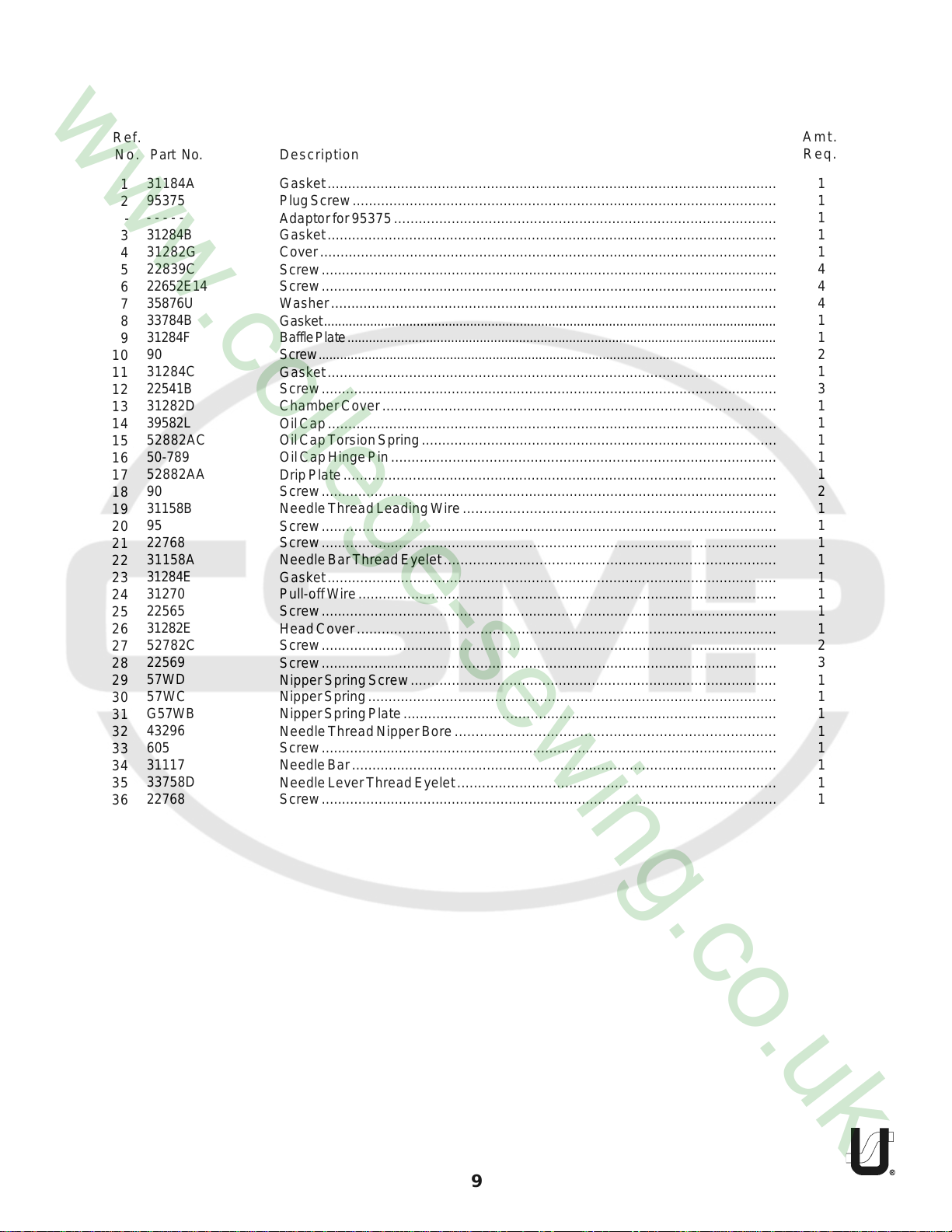
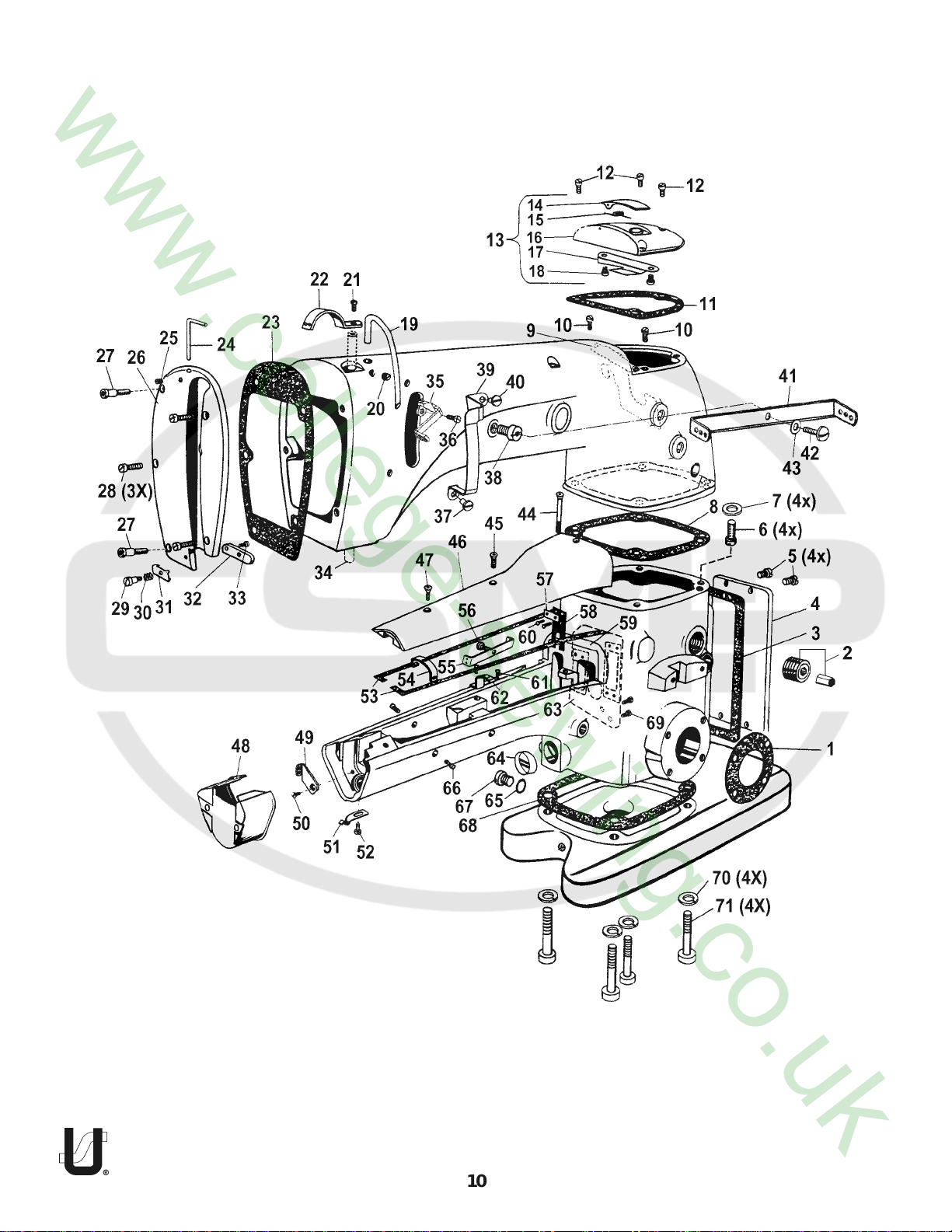
Ref.
No.
Part No.
1
2
-
3
4
5
6
7
8
9
10
11
12
13
14
15
16
17
18
19
20
21
22
23
24
25
26
27
28
29
30
31
32
33
34
35
36
31184A
95375
- - - - -
31284B
31282G
22839C
22652E14
35876U
33784B
31284F
90
31284C
22541B
31282D
39582L
52882AC
50-789
52882AA
90
31158B
95
22768
31158A
31284E
31270
22565
31282E
52782C
22569
57WD
57WC
G57WB
43296
605
31117
33758D
22768
Description
Gasket ..............................................................................................................
Plug Screw ........................................................................................................
Adaptor for 95375 .............................................................................................
Gasket ..............................................................................................................
Cover ................................................................................................................
Screw ................................................................................................................
Screw ................................................................................................................
Washer ..............................................................................................................
Gasket ...............................................................................................................................
Baffle Plate ........................................................................................................................
Screw .................................................................................................................................
Gasket ..............................................................................................................
Screw ................................................................................................................
Chamber Cover ...............................................................................................
Oil Cap ..............................................................................................................
Oil Cap Torsion Spring .......................................................................................
Oil Cap Hinge Pin ..............................................................................................
Drip Plate ..........................................................................................................
Screw ................................................................................................................
Needle Thread Leading Wire ...........................................................................
Screw ................................................................................................................
Screw ................................................................................................................
Needle Bar Thread Eyelet ................................................................................
Gasket ..............................................................................................................
Pull-off Wire .......................................................................................................
Screw ................................................................................................................
Head Cover ......................................................................................................
Screw ................................................................................................................
Screw ................................................................................................................
Nipper Spring Screw .........................................................................................
Nipper Spring ....................................................................................................
Nipper Spring Plate ...........................................................................................
Needle Thread Nipper Bore .............................................................................
Screw ................................................................................................................
Needle Bar ........................................................................................................
Needle Lever Thread Eyelet .............................................................................
Screw ................................................................................................................
Amt.
Req.
1
1
1
1
1
4
4
4
1
1
2
1
3
1
1
1
1
1
2
1
1
1
1
1
1
1
1
2
3
1
1
1
1
1
1
1
1
9
10
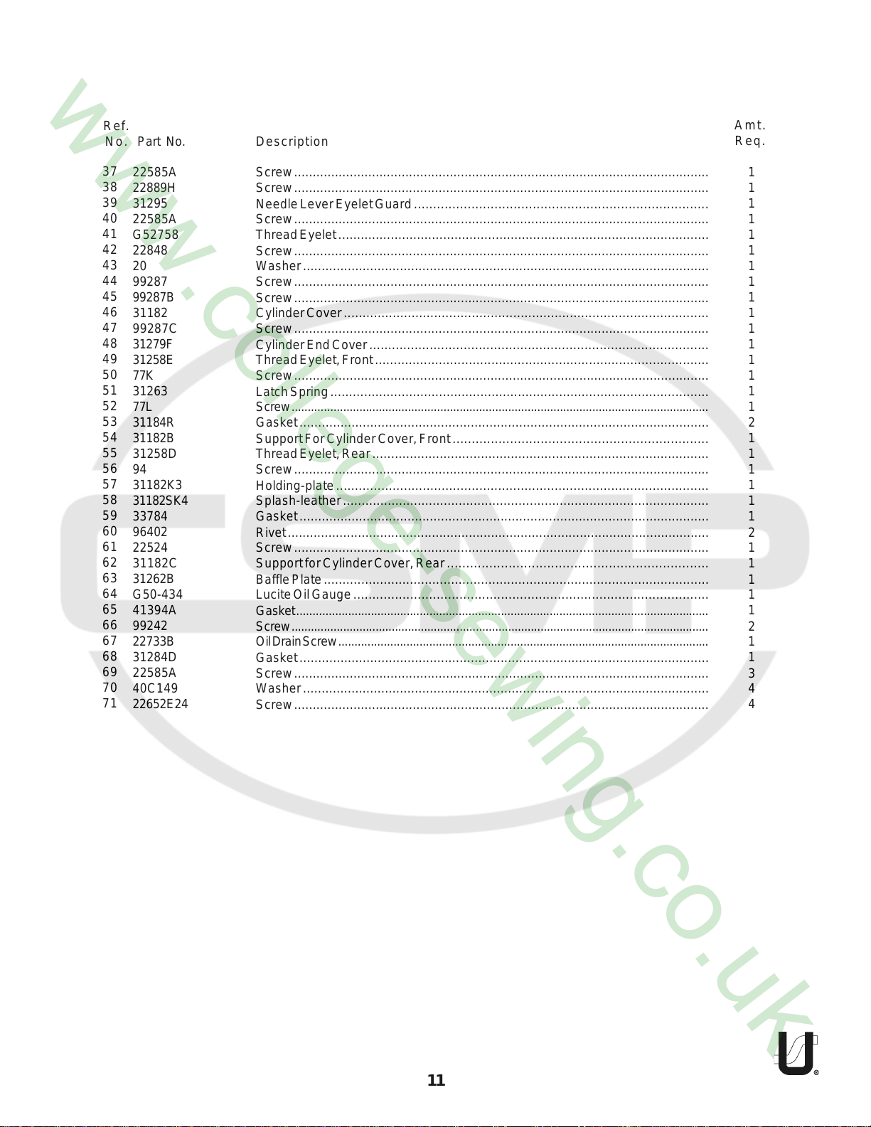
Ref.
No.
Part No.
Description
Amt.
Req.
37
38
39
40
41
42
43
44
45
46
47
48
49
50
51
52
53
54
55
56
57
58
59
60
61
62
63
64
65
66
67
68
69
70
71
22585A
22889H
31295
22585A
G52758
22848
20
99287
99287B
31182
99287C
31279F
31258E
77K
31263
77L
31184R
31182B
31258D
94
31182K3
31182SK4
33784
96402
22524
31182C
31262B
G50-434
41394A
99242
22733B
31284D
22585A
40C149
22652E24
Screw ................................................................................................................
Screw ................................................................................................................
Needle Lever Eyelet Guard .............................................................................
Screw ................................................................................................................
Thread Eyelet ...................................................................................................
Screw ................................................................................................................
Washer .............................................................................................................
Screw ................................................................................................................
Screw ................................................................................................................
Cylinder Cover .................................................................................................
Screw ................................................................................................................
Cylinder End Cover ..........................................................................................
Thread Eyelet, Front .........................................................................................
Screw ................................................................................................................
Latch Spring .....................................................................................................
Screw .................................................................................................................................
Gasket ..............................................................................................................
Support For Cylinder Cover, Front ...................................................................
Thread Eyelet, Rear ..........................................................................................
Screw ................................................................................................................
Holding-plate ...................................................................................................
Splash-leather ..................................................................................................
Gasket ..............................................................................................................
Rivet ..................................................................................................................
Screw ................................................................................................................
Support for Cylinder Cover, Rear ....................................................................
Baffle Plate .......................................................................................................
Lucite Oil Gauge ..............................................................................................
Gasket ...............................................................................................................................
Screw .................................................................................................................................
Oil Drain Screw ..................................................................................................................
Gasket ..............................................................................................................
Screw ................................................................................................................
Washer .............................................................................................................
Screw ................................................................................................................
1
1
1
1
1
1
1
1
1
1
1
1
1
1
1
1
2
1
1
1
1
1
1
2
1
1
1
1
1
2
1
1
3
4
4
11

12

Ref.
No.
Part No.
Description
Amt.
Req.
1
2
3
4
5
6
7
8
9
10
11
12
13
14
15
16
17
18
19
20
21
22
23
24
25
26
27
28
29
30
31
32
33
34
35
36
22586R
51250V
51250D
660-212
34350
719
29476ZL
660-212
51250E
51254K
22562A
660-215
52336A
22564
56354D
31215B
BP108
77
31247
21233FB
61256G
29476ZK
29066Z
80630C
31116H
22559C
999-39W
31222
22768
33758D
31218A16
22565C
96654
31117
31158A
22768
Screw .................................................................................................................
Gasket ................................................................................................................
Washer ...............................................................................................................
"O"Ring ...............................................................................................................
Bushing ...............................................................................................................
Screw .................................................................................................................
Needle Lever Assembly .....................................................................................
"O"Ring ........................................................................................................
Needle Lever Stud ......................................................................................
Needle Bar Connection .............................................................................
Screw ...................................................................................................
Retaining Ring .............................................................................................
Link Pin .........................................................................................................
Screw ..........................................................................................................
Needle Bar Link ...........................................................................................
Needle Lever ..............................................................................................
Screw ...................................................................................................
Screw ...................................................................................................
Pin, for needle lever ...........................................................................................
Nut, for 31247 .....................................................................................................
Washer ...............................................................................................................
Needle Lever Rod Assembly .............................................................................
Bearing ........................................................................................................
Nut, left thread ............................................................................................
Needle Lever Rod Assembly ......................................................................
Screw ...................................................................................................
Needle Bearing ..........................................................................................
Crankshaft ..................................................................................................
Screw .................................................................................................................
Needle Lever Thread Eyelet ..............................................................................
Needle Holder ...................................................................................................
Screw ..........................................................................................................
Pin ................................................................................................................
Needle Bar .........................................................................................................
Needle Bar Thread Eyelet ..................................................................................
Screw .................................................................................................................
1
1
1
1
1
2
1
1
1
1
1
4
2
1
1
1
1
1
1
1
1
1
1
1
1
2
1
1
1
1
1
2
2
1
1
1
13

14

Ref.
No.
Part No.
Description
Amt.
Req.
1
2
3
4
5
6
7
8
9
10
11
12
13
14
15
16
17
18
19
20
21
22
23
24
25
26
27
28
29
30
31
32
33
34
35
36
37
38
31139C
258
31146
G29476X
22729C
31139B
35746C
28B
22894C
31206
22559C
31142A
999-1
31244
31142B
22517
31242
12538
31144C
31144B
31144E
77B
31144D
22729
G97A
18
22517
31144G
22733
12538
31209
31207
31248A
22564D
22562A
31248
22564D
22562A
Feed Rocker Arm ...............................................................................................
Nut ......................................................................................................................
Washer ...............................................................................................................
Feed Lift Connection Assembly For Style 31200Q .............................................
Screw ...........................................................................................................
Bearing ........................................................................................................................
Ball Screw ....................................................................................................................
Screw ...........................................................................................................................
Screw ...........................................................................................................
Eccentric .....................................................................................................................
Screw ...........................................................................................................
Bar For Looper Avoid Lever ................................................................................
Gasket ................................................................................................................
Looper Drive Lever And Link Assembly ..............................................................
Link Pin .........................................................................................................
Screw ...........................................................................................................
Looper Drive Lever ......................................................................................
Nut ...............................................................................................................
Ball Screw ....................................................................................................
Bearing ........................................................................................................
Guide Fork ...................................................................................................
Screw ...........................................................................................................
Ball Screw ....................................................................................................
Screw ...........................................................................................................
Screw ...........................................................................................................
Nut ...............................................................................................................
Screw ..................................................................................................................
Looper Drive Lever .............................................................................................
Screw ..................................................................................................................
Nut ......................................................................................................................
Looper Rear For Class 31200Q ...........................................................................
Looper Front For Class 31200Q ..........................................................................
Looper Holder, Rear ...........................................................................................
Screw ...........................................................................................................
Clamp Screw ..............................................................................................
Looper Holder, Front ..........................................................................................
Screw ...........................................................................................................
Clamp Screw ..............................................................................................
1
1
1
1
2
1
1
1
2
1
2
1
1
1
1
1
1
1
1
1
1
1
1
4
1
1
1
1
1
1
1
1
1
1
1
1
1
1
15

16

Ref.
No.
Part No.
Description
Amt.
Req.
39
40
41
42
43
44
45
46
47
48
49
50
51
52
53
54
55
56
57
58
59
60
61
62
63
64
65
66
67
68
69
70
71
31244A
75A
31116F
999-38
31116C
22559C
999-40
31106
22894C
31144J
77
39543P
18
12538
G12055P
51054A
666-149
31133H
31133K
999-32
31142P
18
21657E
12538
31142M
22894W
31142Q
88
482C
31133M
999-30
31142E
31275A
Looper Rocker Shaft .........................................................................................
Screw ................................................................................................................
Looper Drive Lever Connection ......................................................................
Needle Bearing ................................................................................................
Feed Drive And Looper Avoid Connection Assembly ....................................
Screw .........................................................................................................
Needle Bearing .........................................................................................
Eccentric ...................................................................................................
Screw ..................................................................................................
Looper Avoid Link .............................................................................................
Screw .........................................................................................................
Washer ..............................................................................................................
Nut ....................................................................................................................
Nut ....................................................................................................................
Looper Avoid Drive Link ....................................................................................
Link Pin ...............................................................................................................
Oil Wick ......................................................................................................
Connection Rod ..............................................................................................
Shoulder Screw .................................................................................................
"O"Ring ..............................................................................................................
Bar, For 31142Q .................................................................................................
Nut ....................................................................................................................
Washer ..............................................................................................................
Nut ....................................................................................................................
Link Pin ...............................................................................................................
Screw ................................................................................................................
Feed Drive And Looper Avoid Drive Lever .......................................................
Screw ................................................................................................................
Collar ................................................................................................................
Adjusting Nut ....................................................................................................
"O"Ring ..............................................................................................................
Stud For Looper Avoid Link ...............................................................................
Washer ..............................................................................................................
1
2
1
1
1
2
1
1
2
1
1
1
1
1
1
1
1
1
1
1
1
1
1
1
1
1
1
2
1
1
1
1
1
17

18

Ref.
No.
Part No.
Description
Amt.
Req.
1
2
3
4
5
6
7
8
9
10
11
12
13
14
15
16
17
18
19
20
21
22
23
24
25
26
27
28
990-30
31135C
660-221
22894C
660-199
31136A
31234
99305
31225F
31225A
99306
31134L
G41228A
31136E
31136A
999-30
31139A
999-31
22894W
31139C
31146
35746C
258
96275
31135G
31135E
90
CQ200000000
"O"-Ring .............................................................................................................
Feed Rocker Shaft ............................................................................................
"O"-Ring .............................................................................................................
Screw for 31135C ..............................................................................................
Retaining Ring ...................................................................................................
Link Pin ...............................................................................................................
Feed Bar .............................................................................................................................
Screw .........................................................................................................
Holder For Needle Guard .................................................................................................
Needle Guard ...................................................................................................
Screw .........................................................................................................
Spring ..................................................................................................................................
Screw ..................................................................................................................................
Feed Bar Guide .................................................................................................................
Link Pin ...............................................................................................................
"O"-Ring .............................................................................................................
Feed Bar Adjusting Pin ......................................................................................
"O"-Ring .............................................................................................................
Screw For 31139A ..............................................................................................
Feed Rocker Arm ..............................................................................................
Washer ..............................................................................................................
Ball .....................................................................................................................
Nut .....................................................................................................................
Retaining Ring ...................................................................................................
Feed Bar Shaft ...................................................................................................
Feed Rocker ......................................................................................................
Screw ................................................................................................................
Oil Wick ..............................................................................................................
1
1
1
1
4
2
1
1
1
1
1
1
2
1
1
1
1
1
1
1
1
1
1
2
1
1
2
1
19

20

Ref.
No.
Part No.
Description
Amt.
Req.
1
2
3
4
5
6
7
8
9
10
11
12
13
14
15
16
17
18
19
20
21
22
23
24
25
26
27
28
29
30
31
32
33
34
35
36
37
38
39
40
41
42
43
44
21657W
318
31292
SS7121410TP
22875N
33783H
660-207
33783N
33783M
56356
51256C
34383BA
56383D
22557G
22758C
53783A
33783
88
G402
77
31260
39135
52888B
22562
31260F
31223
22580D
74
31274
31282M
31282H
G43266
51491C
51292D
51292A
51292G
109
51292F2
51292C
95303
31163
95259
96851
31282J
Tension Release Lever Shaft .............................................................................
Screw ................................................................................................................
TensionRelease and Foot Lifter LeverConnection ..........................................
Screw .........................................................................................................
Screw ................................................................................................................
Presser Foot Lifter Lever ....................................................................................
Oil Seal Ring .......................................................................................................................
Presser Foot Lifter Lever, Internal .....................................................................................
Presser Foot Lifter Lever Connecting Rod ......................................................................
Presser Spring Regulator ..................................................................................................
Presser Bar Spring ..............................................................................................
Presser Foot Lifter Lever Bell Crank ...................................................................
Presser Foot Lifter Lever Bell Crank Spring ........................................................
Screw ................................................................................................................
Screw ................................................................................................................
Lifter Lever Link .................................................................................................
Presser Bar Connection ....................................................................................
Screw .........................................................................................................
Screw ................................................................................................................
Screw ................................................................................................................
Presser Bar .........................................................................................................
Presser Bar Guide Bar ........................................................................................
Collar For Presser Foot ......................................................................................
Screw ................................................................................................................
Presser Bar Insert For Style 31200Q ....................................................................
Looper Thread Take-up ....................................................................................
Screw ................................................................................................................
Screw ................................................................................................................
Collar ................................................................................................................
Case For Take-up Complete ............................................................................
Case For Take-up .......................................................................................
Nut ..............................................................................................................
Thread lead in Guide .................................................................................
Tension Thread Eyelet ................................................................................
Tension Post Ferrule ...................................................................................
Tension Post ...............................................................................................
Tension Disc ...............................................................................................
Spring .........................................................................................................
Tension Nut ................................................................................................
Screw .........................................................................................................
Spring .........................................................................................................
Nut ..............................................................................................................
Pin ...............................................................................................................
Cover .........................................................................................................
1
1
1
1
1
1
1
1
1
1
1
1
1
1
1
1
1
2
1
1
1
1
1
2
1
1
2
2
2
1
1
2
2
2
2
2
4
2
2
2
1
2
1
1
21

22

Ref.
No.
Part No.
Description
Amt.
Req.
45
46
47
48
49
50
51
52
53
54
55
56
57
58
59
60
61
62
63
64
65
66
67
68
69
70
71
43266
51491C
51292D
51292A
51292G
109
51292F4
51292C
80557
52892
22598C
21657-3
94
69H
G29389U
31204
22729
53304C
31257
J87J
53304B
28
73A
52958L
22588A
31104
52804E
Nut ....................................................................................................................
Thread Lead-in Guide ......................................................................................
Tension Thread Eyelet .......................................................................................
Tension Post Ferrule ..........................................................................................
Tension Post ......................................................................................................
Tension Disc ......................................................................................................
Tension Spring-Needle .....................................................................................
Tension Nut .......................................................................................................
Washer ..............................................................................................................
Tension Post Support ........................................................................................
Screw ................................................................................................................
Tension Disc Separator .....................................................................................
Screw ................................................................................................................
Washer ..............................................................................................................
Take-up Shield Complete ................................................................................
Cast-off and Retaining Finger Support Bracket .......................................
Screw ..................................................................................................
Cast-off ......................................................................................................
Take-up Shield ...........................................................................................
Screw .........................................................................................................
Cast-off Plate .............................................................................................
Screw .........................................................................................................
Screw .........................................................................................................
Eyelet .........................................................................................................
Screw .........................................................................................................
Retaining Finger ........................................................................................................
Retainer Support .......................................................................................................
1
2
2
2
2
4
2
2
2
1
1
1
2
2
1
1
1
1
1
2
1
2
2
2
1
1
1
23

24

Ref.
No.
Part No.
Description
Amt.
Req.
*1
31220R16
2
31130S
3
31130T
4
31230R16
5
91
6
11940
7
605
8
22524
9
31224Q16
10
31134M
11
31134N
12
22716
13
99293
14
31205Q
* 31220R16 Presser Foot Assembly not supplied
with machine style 31200AQ64Z6
Presser Foot Assembly For Style 31200Q64 .......................................................
Yielding Section, Left .................................................................................
Yielding Section, Right ...............................................................................
Presser Foot Bottom ...................................................................................
Screw .........................................................................................................
Spring .........................................................................................................
Screw .........................................................................................................
Screw ................................................................................................................
Throat Plate ......................................................................................................
Stripper .............................................................................................................
Plate ..................................................................................................................
Screw ................................................................................................................
Screw ................................................................................................................
Feed Dog ..........................................................................................................
1
1
1
1
1
1
1
2
1
1
1
2
1
1
25

26

Ref.
No.
Part No.
Description
Amt.
Req.
1
2
3
4
5
6
21201
12288403
TT17
21388
G43294B
28604R
Screw Driver ......................................................................................................
Thread Tweezers ...............................................................................................
Wrench 9/32" ....................................................................................................
Wrench 3/8" ......................................................................................................
Oil Can ..............................................................................................................
Container of Oil .................................................................................................
1
1
1
1
1
1
27

28

Ref.
No.
Part No.
Description
Amt.
Req.
1
2
21101W4
51295B
Thread Stand............................................................................................................
Mounting Isolator ....................................................................................................
1
4
29

30

Ref.
No.
Part No.
Description
Amt.
Req.
1
2
3
4
5
6
7
8
9
10
11
12
13
14
15
16
21177A
22647K24
1349A5
21114W
258
23105B
21182AP
22581
52782C
31282E
22569
31270
22565
31278
753
188D
Tape Reel Tension Spring Complete ................................................................
Thumb Screw .............................................................................................
Spring .........................................................................................................
Spool Pin ...........................................................................................................
Nut ....................................................................................................................
Tape Reel Bracket ............................................................................................
Tape Tension Bracket .......................................................................................
Screw ................................................................................................................
Stud ...................................................................................................................
Head Cover ......................................................................................................
Screw ................................................................................................................
Pull-off Wire .......................................................................................................
Screw ................................................................................................................
Tape Holder Disc ..............................................................................................
Spool Axle Cone ...............................................................................................
Thumb Screw ....................................................................................................
1
1
1
1
3
1
1
2
2
1
3
1
1
2
1
1
31

NUMERICAL INDEX OF PARTS
Part No. Page No. Part No. Page No. Part No. Page No.
109 ........... 21, 23
11940 ........... 25
12288403 ...... 27
12538 ...... 15, 17
1349A5 ......... 31
15430L ......... 7
18 ......... 15, 17
188D ........... 31
20 ............. 11
21101W4 ........ 29
21114W ......... 31
21177A ......... 31
21182AP ....... 31
21201 ........... 27
21212 ............. 7
21233FB ........ 13
21388 ........... 27
21657-3 ......... 23
21657E ........... 17
21657W ........... 21
21657X ........... 7
22517 ............. 15
22524 ........ 11, 25
22541B ........... 9
22557G .......... 21
22559C ..... 13, 15
22559C .......... 17
22562 ............. 21
22562A ..... 13, 15
22564 ............. 13
22564D ........... 15
22565 ........ 9, 31
22565C ......... 13
22569 ........ 9, 31
22569B ........... 7
22574 .............. 7
22580D .......... 21
22581 ........ 7, 31
22585A ........... 11
22586R ........... 13
22588A ........... 23
22598C ........... 23
22647K24 ........ 31
22652E14 ......... 9
22652E24 ....... 11
22716 .............. 25
22729 ......... 15, 23
22729AB ......... 7
22729B ........... 7
22729C ........... 15
22733 ............. 15
22733B ........... 11
22758C ........... 21
22768 ......... 9, 13
22839C ............ 9
22848 ............. 11
22875N ........... 21
22889H ........... 11
22894C ..... 15, 17
22894C .......... 19
22894G ........... 7
22894W .... 17, 19
23105B .......... 31
258 ..... 15, 19, 31
28 ................ 23
28604R ......... 27
28B ............... 15
29066Z ........... 13
29476ZK ......... 13
29476ZL ......... 13
31104 ............. 23
31106 ............. 17
31116C ........... 17
31116F ........... 17
31116H ........... 13
31117 ......... 9, 13
31121A ............. 7
31130S ........... 25
31130T ........... 25
31133H ........... 17
31133K ........... 17
31133M ........... 17
31134L ........... 19
31134M ........... 25
31134N ........... 25
31135C ........... 19
31135E ........... 19
31135G ........... 19
31136A ........... 19
31136E ........... 19
31139A ........... 19
31139B ........... 15
31139C ...... 15, 19
31140 ............. 7
31140A ............ 7
31140B ............ 7
31142A ........... 15
31142B ........... 15
31142C ............ 7
31142E ........... 17
31142M ........... 17
31142P ........... 17
31142Q ........... 17
31144B ........... 15
31144C ........... 15
31144D ........... 15
31144E ........... 15
31144G ........... 15
31144J ........... 17
31146 ....... 15, 19
31154 .............. 7
31155 .............. 7
31158A ....... 9, 13
31158B ............. 9
31163 ............. 21
31175C ............. 7
31182 ............. 11
31182B ........... 11
31182C ........... 11
31182K3 ......... 11
31182SK4 ....... 11
31184A ............. 9
31184R ........... 11
31190B ............ 7
31194 .............. 7
31194A ............ 7
31194B ............ 7
31204 ............. 23
31205Q ........... 25
31206 ............. 15
31207 ............. 15
31209 ............. 15
31215B ........... 13
31218A16 ....... 13
31220R16 ....... 25
31222 ............. 13
31223 ............. 21
31224Q16 ....... 25
31225A ........... 19
31225F ........... 19
31230R16 ....... 25
31234 ............. 19
31242 ............. 15
31244 ............. 15
31244A ........... 17
31247 ............. 13
31248 ............. 15
31248A ........... 15
31257 ............. 23
31258D ........... 11
31258E ........... 11
31260 ............. 21
31260F ........... 21
31262B ........... 11
31263 ............. 11
31270 ......... 9, 31
31274 ............. 21
31275A ........... 17
31278 ............. 31
Part No. Page No.
31279F ........... 11
31282 ............. 31
31282D ............ 9
31282E ....... 9, 31
31282G ............ 9
31282H ........... 21
31282J ........... 21
31282M ........... 21
31284B ............ 9
31284C ............ 9
31284D ........... 11
31284E ............ 9
31284F ............ 9
31291 .............. 7
31292 ............. 21
31295 ............. 11
318 ............... 21
33758D ....... 9, 13
33783
33783H ........... 21
33783M ........... 21
33783N ........... 21
33784 ............. 11
33784B ........... 9
34350 ............. 13
34354 .............. 7
34383BA ......... 21
35746C ...... 15, 19
35876U ............ 9
39135 ............. 21
39543P ........... 17
39582L ............ 9
40C149 ........... 11
41394A ........... 11
43266 ............. 23
43296 .............. 9
43443Q ............ 7
482C .............. 17
50-789 .............. 9
51054A ........... 17
51250D ........... 13
51250E ........... 13
51250V ........... 13
51254K ........... 13
51256C ........... 21
51292A ..... 21, 23
51292C ..... 21, 23
51292D ..... 21, 23
51292F2 ......... 21
51292F4 ......... 23
51292G ..... 21, 23
51294Z ............ 7
51295B ........... 29
............. 21
32

NUMERICAL INDEX OF PARTS
Part No. Page No. Part No. Page No.
51491C ...... 21, 23
52336A ........... 13
52782C ....... 9, 31
52804E ........... 23
52882AA .......... 9
52882AC .......... 9
52888B ........... 21
52892 ............. 23
52958L ........... 23
53304B ........... 23
53304C ........... 23
53394Q ............ 7
53783A ........... 21
56354D ........... 13
56356 ............. 21
56383D ........... 21
57WC ............. 9
57WD ............. 9
605 ........... 9, 25
61256G ........... 13
61321J ............ 7
61321L ............ 7
660-199 ......... 19
660-202 .......... 7
660-207 ......... 21
660-212 ......... 13
660-215 ......... 13
660-221 ......... 19
666-149 ......... 17
666-201 .......... 7
666-209 .......... 7
666-214 .......... 7
69H ............. 23
719 .......... 7, 13
73A ............. 23
74 ............... 21
753 ............. 31
75A ........... 17
77 ..... 13, 17, 21
77B ............. 15
77K ............. 11
77L ............. 11
80262I ........... 7
80557 ............. 23
80630C ........... 13
87U .............. 7
88 ........ 17, 21
88D ........... 31
90 ............ 9, 19
91 ............. 25
94 ......... 11, 23
95 ............. 9
95259 ............. 21
95303 ............. 21
95375 .............. 9
96275 ............. 19
96402 ............. 11
96654 ............. 13
96851 ............. 21
990-30 ........... 19
99242 ............. 11
99287 ............. 11
99287B ........... 11
99287C ........... 11
99293 ............. 25
99305 ............. 19
99306 ............. 19
999-1 ........ 7, 15
999-30 ...... 17, 19
999-31 ........... 19
999-32 ........... 17
999-35 ............ 7
999-36 ............ 7
999-38 ........... 17
999-39W ........ 13
999-40 ........... 17
BP108 .......... 13
CQ200000000 ... 19
G12055P ......... 17
G29389U ......... 23
G29476X .......... 15
G402 ............. 21
G41228A ......... 19
G43266 .......... 21
G43294B ........ 27
G50-434 ........... 11
G52758 ........... 11
G56375 ............ 7
G57WB ............ 9
G97A ............... 15
J87J ............. 23
SS7121410TP ... 21
TT17 ............. 27
33

NOTES

NOTES

 Loading...