

Page 1
...
FINEST
•
QUA
LilY
INDUSTRI
SEWING
MACHINE$
r
6J
A L
63900
WS 4
PL
AM
2800
1096
Z-900
LAH
-1
/
A D J U S T I N G
LIST
I N S T R U C T I 0 N S
AND
OF
PARTS
-
..
Page 2
'
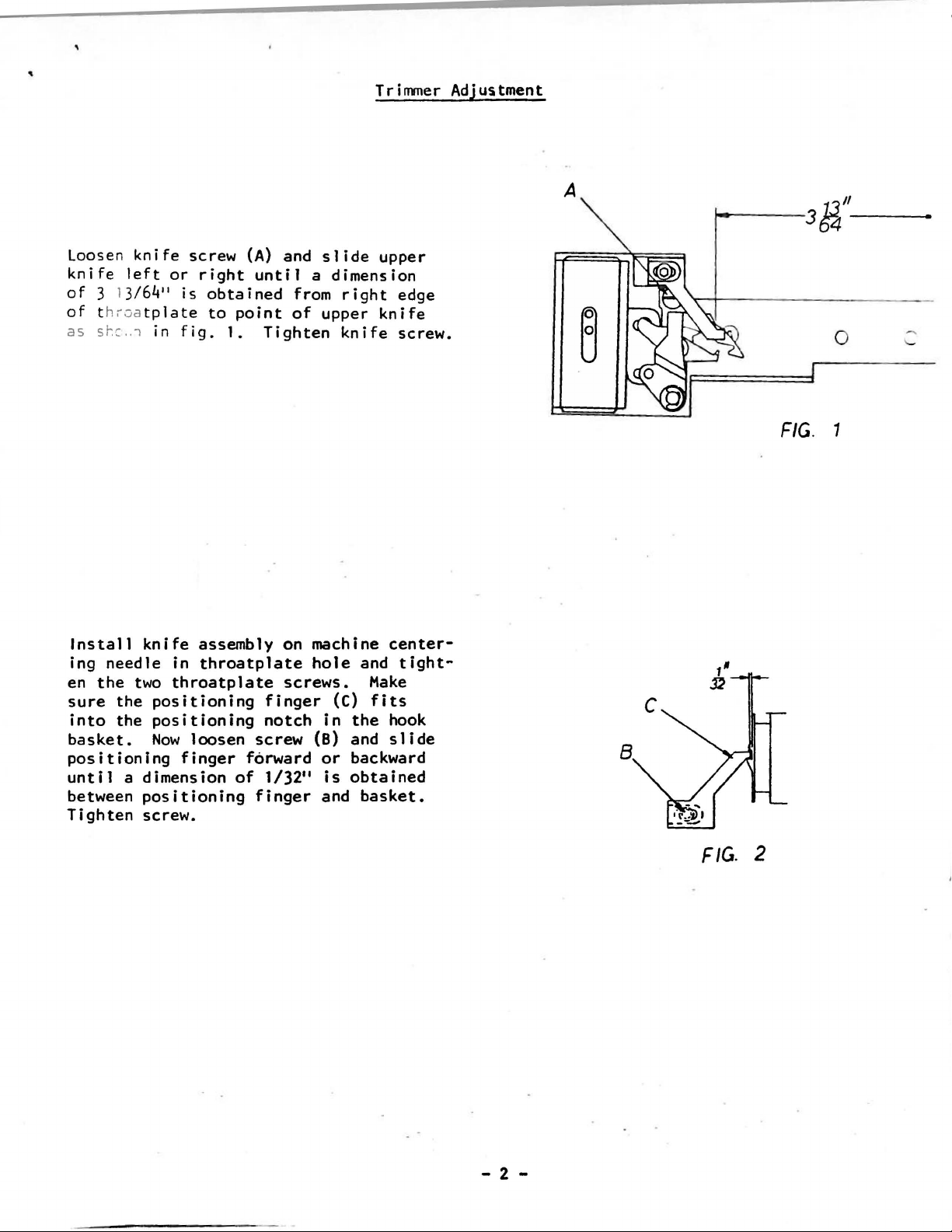
Trimmer Adjustment
A
1J"
36'+---
loosen
knife
of
of
as
Install
ing
en
sure
into
left
3
1
3/6~
throa
st-:c
..
needle
the
the
the
knife
tplate
1 in
knife
two
basket.
positioning
until
between
Tighten
a dimension
positioning
screw.
or
11
screw
right
is
fig.
(A)
until
obtained
to
point
1.
Tighten
assembly on machine
in
throatplate
throatplate
positioning
positioning
Now
loosen
finger
finger
notch
screw
forward
of
1/32
finger
and
slide
a dimension
from
of
right
upper
knife
hole
screws.
(C)
in
(B)
and
or
11
backward
is
obtained
and
upper
knife
center-
and
Make
fits
the
hook
slide
basket.
edge
screw.
tight-
FIG
0
. 1
- 2 -
FIG.
2
Page 3

1.
Rotate
direction
tom
of
its
protective
(B, by
Rotate
of
approximately one
notch
the
notch
opening
handwheel in
until
needle
stroke.
cover
disc
is
centered
(Fig.
4).
Remove
(A)
and loosen
(C)
until
Tighten
Synchronizer
counterclockwise
bar
is
at
the
synchronizer
set
screw
half
over
the
set
turn.
opening
the
shutter
screw.
bot-
Adjustment
FIG.
r
S~TTER
3
2.
Now
is
on
1/8
inch from
Loosen
(D)
until
shutter
caution
notch
rotate
its
up
set
the tab
opening
not
disc.
handwheel
stroke
the
screw
to
change
Tighten
top
(B)
is
(Fig.
until
and
is
of
its
and
turn
centered
4)
while
the
set
screw.
take-up
approxlmatley
stroke.
tab
disc
over
the
using
setting
of
I
rSH
~f\JOTCHEO
'
(SHUTTER
/
.
~
I
U
TTER
sHuTTeR
TAB
FIG.
OPEfJING
DISC
OPeNING
DISC
4
- 3 -
Page 4
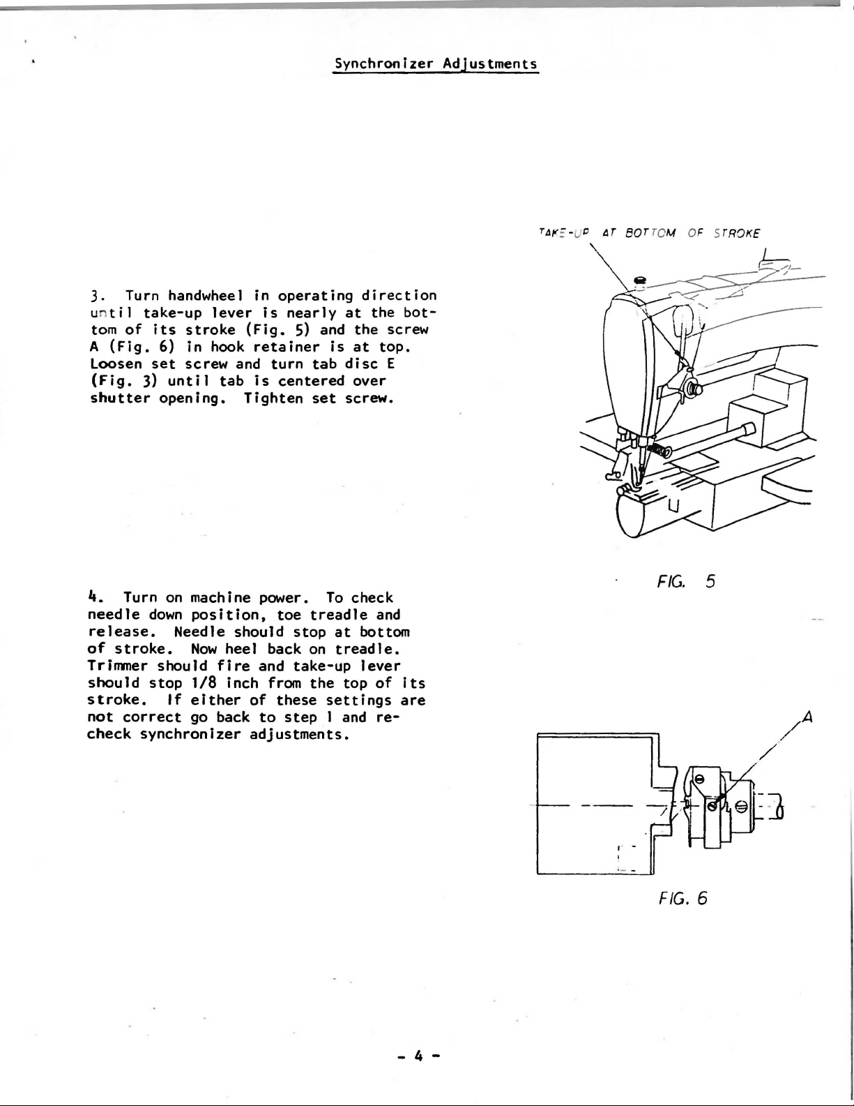
Synchronizer Adjustments
3. Turn handwheel in
u
til
take-up
tom
of
its
A
(Fig.
loosen
(Fig.
shutter
4.
needle
release.
of
stroke.
Trimmer should
should
stroke.
not
check
6) in hook
set
3)
until
opening.
Turn
on
down
stop
If
correct
synchronizer
lever
stroke
screw and
machine power.
position,
Needle should
Now
1/8
either
go
(Fig.
retainer
tab
is
Tighten
heel back
fire
inch from
of
back
adjustments.
operating
is
nearly
5)
turn
centered
toe
stop
and
take-up
these
to
step
at
and
is
at
tab
disc
over
set
screw.
To
check
treadle
at
on
treadle.
the
top
settings
1 and
direction
the
bot-
the
screw
top.
E
and
bottom
lever
of
its
are
re-
FIG.
5
- 4 -
,. -
FIG.
6
Page 5
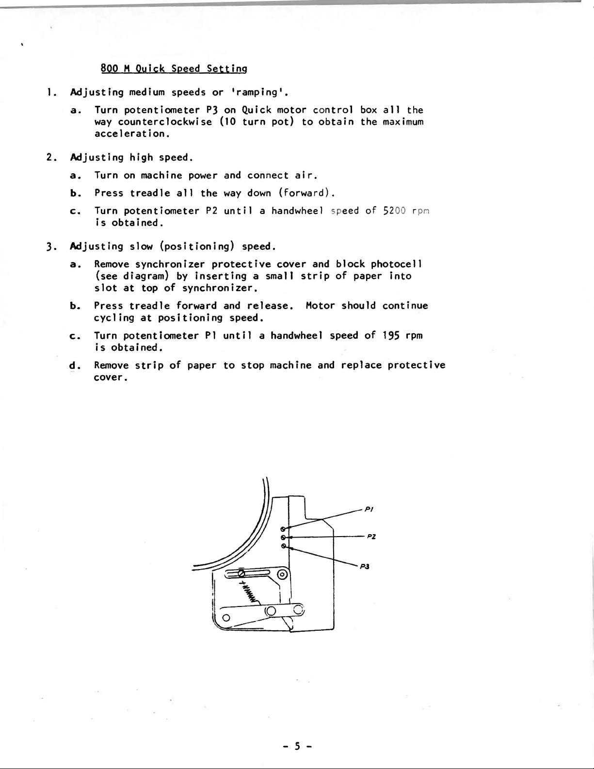
1.
2.
3.
c.
BooM Ouick Speed
Adjusting
a.
Turn
way
acceleration.
Adjusting
a.
Turn
b.
Press
c.
Turn
is
obtained.
Adjusting
a.
Remove
(see
slot
b.
Press
cycling
Turn
is
obtained.
medium
potentiometer
counterclockwise
high
on
machine power and
treadle
potentiometer
slow
synchronizer
diagram)
at
top
treadle
at
potentiometer
speeds
speed.
all
the
(positioning)
by
inserting
of
synchronizer.
forward and
positioning
Setting
or
'ramping'.
PJ on Quick motor
(10
turn
way
P2
until
speed.
protective
speed.
Pl
until
pot)
connect
down
a handwheel speed
a
small
release.
a handwheel speed
air.
(forward).
cover
control
to
obtain
and
strip
Motor
box
the
block
of
paper
should
all
the
maximum
of 5200 rpn
photocell
into
continue
of
195
rpm
d.
Remove
cover.
strip
of
paper
to
stop
machine and
replace
protective
- 5 -
Page 6
SERVICING
INSTRUCTIONS
880M
Assembly/Disassembly
1.
Remove V
2.
Disconnect
3.
Remove
moving
unit
4.
Keep
to
5.
Place
flat
Use
inserting
socket
shaft
brake
clutch
6.
Clean
surfaces
replace
keep
caution
belt
cables
the
three
last
screw,
will
clutch/brake
surface.
not
the
the
clutch/brake
of
of
the
of
the
discs
disc
the
surfaces
should
the
clutch/brake
during
for
projects
plates.
for
and
screws
fall.
Separate
the
solenoid
end
end
bell.
wear.
be
Inspection
guard.
which
housing
disassembly
bell.
of
smooth.
place
beyond
the
attach
located
hand
tilted
disc
housing,
the
electrical
Slide
Put
If
cork
face
or
Replacement:
clutch
approximately
under
sligh':
in
pla
pulley
clutch
and
the
the
end
surfaces
the
outer
plates
If
you
housing
clutch/brake
ly
d·
Jwllv.·a:-.::
ce.
side
facing
solenoid
reassembly
connection
clutch
bell
metal
with
find
and
aside
are
an
nicks
from
smooth
rim,
to
control
120°
apart.
housing so
(pulley side dov.'Tl)
upward,
the
to
ensure
pins
brake
and
inspect
and
discs
oiled
and
gouges
end
into
discs
if
are
rag.
box.
When
that
on a clean
bell.
alignment
the
mating
of
the
the
clutch/
cork
These
on
on
okay.
them,
re-
Note:
and
splined
7.
8.
9.
10.
11.
Thoroughly
dry
rag.
120°.
Apply a
clutch/brake
Reassemble
(part
condition.
certain
Reinstall
cedures
Once
as
Spread
small
No.
that
outlined
reinstallation
outlined
clean
Apply
408.009)
the
grease
the
amount
discs
the
clutch/brake
To
assure
the
clutch/brake
the
grease
move.
and
vent
in
sections
is
cork
faces
(Quick
evenly
of
grease
This
the
stop
proper
holes
discs
completed,
of
No.
over
to
will
discs
washer
operation
are
lined
and
3.,
2.,
the
clutch/brake
051.011)
the
the
brass
assure
making
(part
of
up.
housing
and
check
the
in
3-one
entire
splines
proper
sure
1.
the
No.
the
cooling
by
clutch/brake
discs
inch
cork
reversing
surfaces.
on
which
action.
rubber
250.008)
system,
using a clean,
segments
the
"O"
rings
are
the
clearance
in
good
make
pro-
every
- 6 -
Page 7
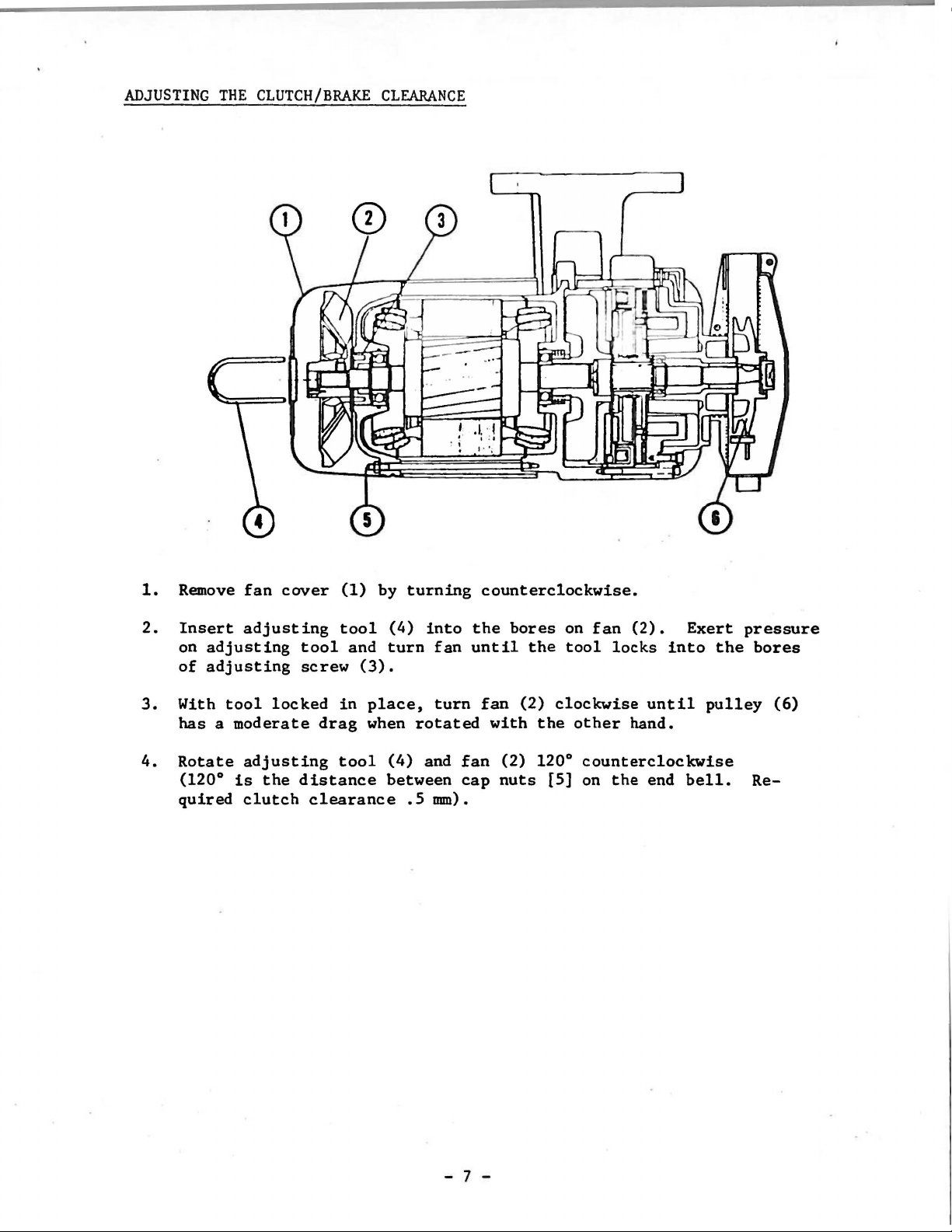
ADJUSTING
THE
CLUTCH/BRAKE
CLEARANCE
1.
Remove
2.
Insert
on
adjusting
of
adjusting
3.
With
has a moderate
4.
Rotate
quired
tool
(120°
fan
cover
adjusting
locked
adjusting
is
the
clutch
(1)
tool
tool
screw
distance
and
in
drag
tool
clearance
by
(4)
turn
(3).
place,
when
(4)
between
turning
into
fan
turn
rotated
and
.5
mm).
counterclockwise.
the
until
fan
fan
cap
bores
with
(2) 120°
nuts
the
(2)
the
[5]
on
tool
clockwise
other
fan
(2).
locks
hand.
counterclockwise
on
the
into
until
end
Exert
pulley
bell.
pressure
the
bores
(6)
Re-
- 7 -
Page 8
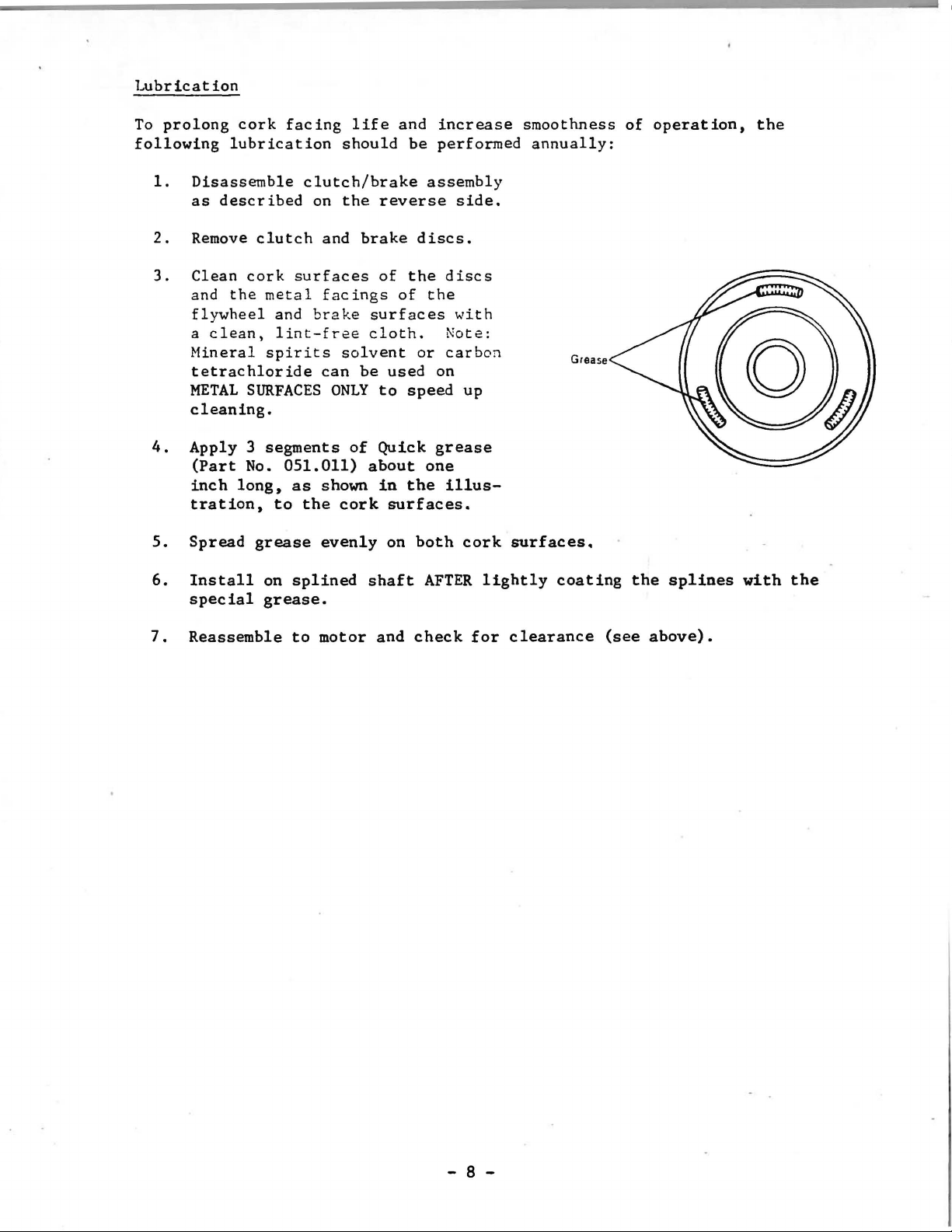
Lubrication
To
prolong
following
1.
Disassemble
as
2.
Remove
3.
Clean
and
flywheel
a
clean,
Mineral
tetrachloride
METAL
cleaning.
4.
Apply 3 segments
(Part
inch
tration,
cork
facing
lubrication
described
clutch
cork
the
metal
and
lint-free
spirits
SURFACES
No.
051.011)
long,
to
life
should
clutch/brake
on
the
and
brake
surfaces
facings
brake
cloth.
solvent
can
be
ONLY
of
about
as
shown
the
cork
and
be
reverse
discs.
of
the
of
surfaces
or
used
to
speed
Quick
one
in
the
surfaces.
increase
performed
assembly
side.
discs
the
'..'ith
Note:
carbon
on
up
grease
illus-
smoothness
annually:
Grease
of
operation,
the
5.
Spread
6.
Install
special
7.
Reassemble
grease
on
splined
grease.
to
evenly
motor
on
shaft
and
both
AFTER
check
cork
lightly
for
surfaces.
coating
clearance
(see
the
above).
splines
with
the
- 8 -
Page 9
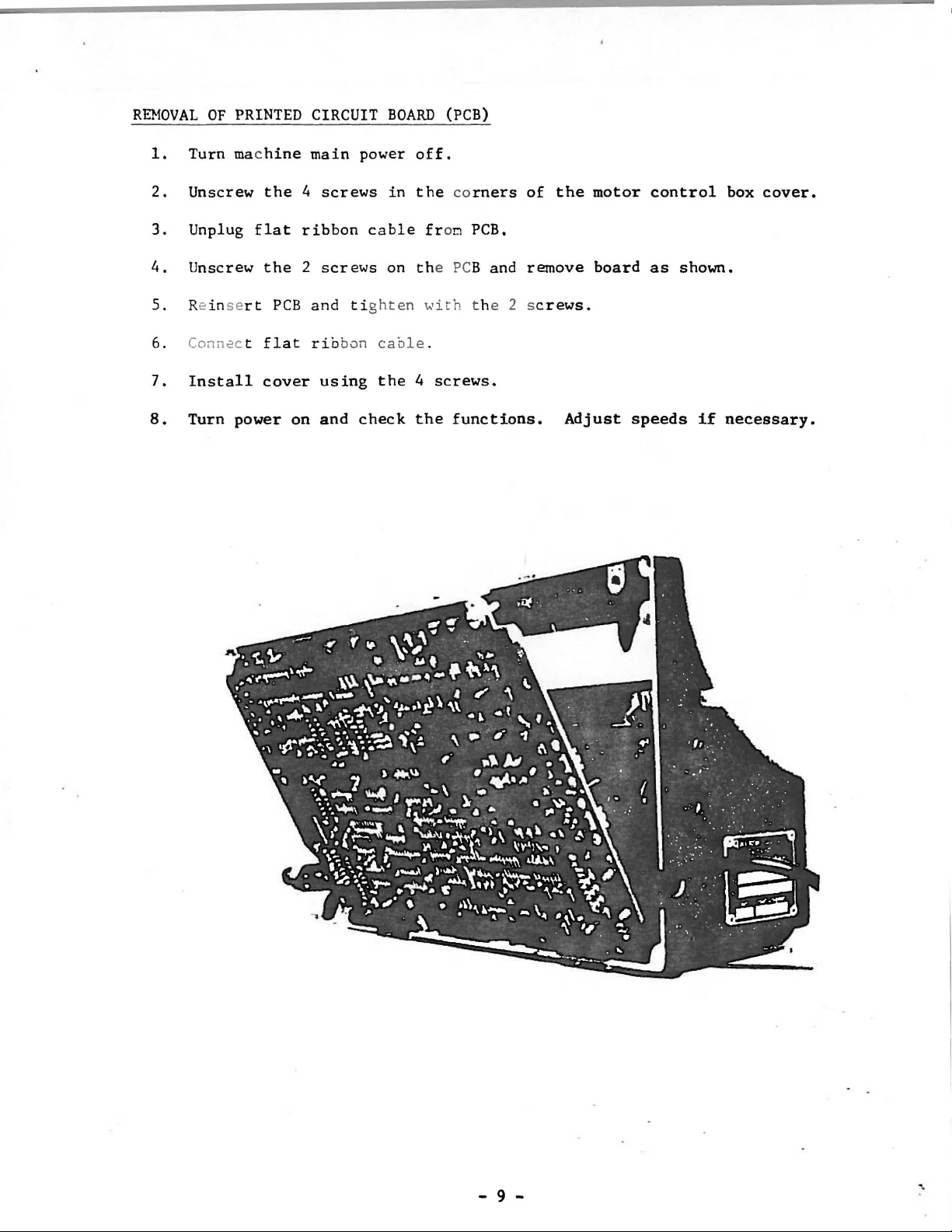
REMOVAL
1.
Turn mac
2.
Unscrew
3.
Unplug
4.
Unscrew
OF
PRINTED
CIRCUIT
hine
main
the 4 screws
flat
ribbon
the 2 screws
BOARD
power
in
cable fron
on the PCB and remove
(PCB)
off.
the corners
PCB,
of
the
motor
board
control
as
shown.
box
cover.
5. Re
6. Connec t
7.
8.
insert
Install
Turn power on
PCB
flat
cover
and tighten
rib
bon
cable
using
and
the 4 screws.
check
with
.
the
t he 2 s
functions.
crews.
Adjust
speeds
if
necessary.
- 9 -
Page 10

ELECTRICAL
The
terminal
connection
three-phase.
diagram
below.
strip
for
of
380
volts
Details
the
of
motor
A.C.
both
is
designed
or
Delta
connection
connections
to
accommodate
are
illustrated
for
220
either
volts
in
the
the
A.C.,
wiring
star
Terminal
WIRING
DIAGRAM
Box
- 10 -
Page 11

SOLENOID
CONNECTIONS
T n
mm~
r
So
lenotd
Sot~notd
H~rncss
610E-287
I
PN=UMATIC CONt,ECTIONS
F~ot
Lift
f'·
t¥t
J.
r.,.,_
w''"
'~~
J
M~·n
Fie!Jui.Jtcr
._IMPORTANT:
retr~ctcd
ro
'c
-
11
-
prc<tcnt
w~t'>t:
tn•
pos' t
lltufc
two
A
f-er
conn~t•ng
ion
1:1c
fore
IJ'ccn~nr
,,,
l•nes.
sm
tritrWT..:or,
carcncr
DDetating
d4md't:.
is
If
rn
JI
..
JyS
·
not,
Page 12

PNEUMATIC
52
DIAGRAM
TRE
:.o_E
At=-• AL
vE
SU~::J_.
~M-IN
0
EG
uL t.
-cq
bOPS/
51
KN=E-OPE.::tA
AtFi
: A_.·£
1----B--
..
EC
P=ESSE;:;
-~~-
FOLDE-=i
I~
=oo~
,...
--· --
•
.J-=
·=.,
-
12
-
Page 13

B0t3BIN COUNTER WIRING DIAGRAM
l
C:loD
Tl
o/11
119 '-)
+
+
1.
Install
chine.
holding
ing
the
other
L_
Operating
a
fully
Set
counter
the
reset
appropriate
three
black
___
_
Instructions
wound
to a value
button
digit
buttons.
bobbin in
of
in
while
by
pressing
ma-
900
by
index-
the
BOBBIN
--
• I
r
~-----------
I
I
t
39011.
RESISTOR
---=---:
______; INDICATOR LAMP
BOBBIN
COUNT
SOLENOID
=00 1
CUT-OFF
RUN-OUT
PPTIONAL}
LI
FT
SWITCH
12VOC
2.
Sew
the
complete bobbin keeping watch
for
when
counter
time
mer
pulses).
3.
Subtract
900
-
of
garments
bobbin.
this
that
~.
Reset
count
5.
-
When
bobbin
on and
when
dle.
button
the
will
a garment
this
figure
that
Also
number
might
to
occur.
the
obtained.
the
run-out
the
presser
the
operator
When
and
this
Install
bobbin
count
the
thread
down
is
completed
resulting
one number each
represents
can be
sewn
subtract a few
account
counter
counter
warning 1
heels
digits
reaches
foot
for
ight
will
back
happens,
new
bobbin.
runs
(counts
count from
the
from a full
cycles
any
variance
to
zero
wU 1 come
not
on
press
the
out.
number
the
the
11ft
the
reset
The
trim-
from
final
_
trea-
-
RESET
BUT
"!
ON
Page 14

@
~
,
'
~-<:.(jj)
Thread
Viper
Assembly
No.
1
2
3
"
s
6
7
8
9
10
11
Qty.
Thread Wiper
1
1
1
2 B.H. Screw 8-32
2
2
2
2
1
10-32
Air
Thread Wiper
118
Nut
Screw .183-32
Washer
Thread Wiper
Set
Description
(Non-Rotating)
Male
Cylinder
lock
8-32
Screw
Connector -
Washer
6-32
Air
Cylinder & Nut
Bracket
Bracket
X
3/8
Clamp
Poly
Part
671-A-15
671-F-17
AS-9-3
AS-9-4
RM-2813-3
RM-27lt7-6
RH-2791-1
22569-J
RM-3293-5
AS-9-5
Rt-:-2808-1
I
12
13
lit Flow Control
15 2
1
1
Thread Wiper
Nut 10.-32
Hale
10-3~1~~nnector
Wire
- Barbed
AS-9-6
651-H
671-37
6]1-F-4
Page 15
@
No.
2
3
IJ
5
6
7
8
9
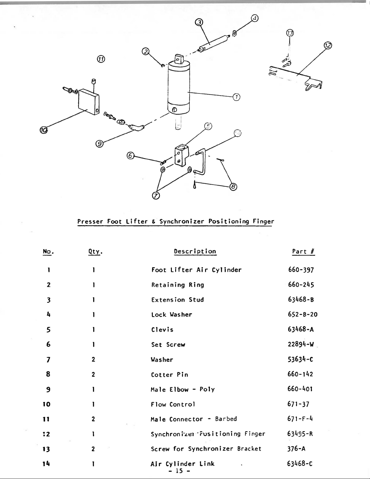
Presser
Qty.
2
2
Foot
Lifter
&
Synchronizer
Description
Foot
Retaining
Extension
lock
Clevis
Set
Washer
Cotter
Male Elbow -
lifter
Ring
Stud
Washer
Screw
Pin
Positioning
Air
Cylinder
Poly
Finger
Part
#
660-397
660-245
63468-B
652-B-20
63468-A
22894-W
53634-c
660-142
660-401
.
10
11
13
2
2
l!J
Flow
Male Connector - Barbed
Synchron
Screw
AJr
Control
i-
.Lt:!t
for
Synchronizer
Cylinder
- 15 -
-·
rus
link
it
ion i
ng
Finger
Bracket
671-37
671-F-4
63495-R
376-A
63468-c
Page 16

Folder
Opener
No.
1
2
3
,
5
Qty.
2
Description
Folder
Folder
Male Elbow
Plunger
Set
Opener Cyl.
Opener
Screw
Air
Cylinder
- Barbed
6/32 X 1/4
Bracket
Part
AS-9-1
671-A-56
RM-3]28-1
AS-9-2
RM-2808-t
#
- 16-
Page 17

_,
I
I
r
e1"rf
J~
No.
·
·a
\
(/
)
..
Qty.
~
~
I
I
l i
'I
I
\
I
I
I
Trimmer,
Tension
Description
Release,
Hemmer
Part
H
2
3
4
5
6
7
1~
8
9
10
11
12
..
3
3
3
Trimmer Assembly
Tension
Throatplate
2
,
,.
_
Throatplate
Hemmer
Adapter
Air
1'"~1"-l<;oc-
1!6
lock
Screw
M
ale
Fe
ma le
Male Elbow Barbed
Release
Assembly
Stud
Tube
fot;<;y
Washer
Connector
Coupling
Assembly
Needle Hole
Screws
A:~
tlDS~
Poly
10-32
10-32
Insert
C;s-r.~~,·-16.)
639-34-ooo
634-27-00
63928-A
22569-C
23564
21237-CK
AS-9-7
~iH3·Z.8'
RM-2747-2
22585-A
671-F-17
671-F-29
671-F-54
13
N/s
1
Check
Conical
Spring
Tension
,
Spring
92-5-J0-1
92-5-25-1
Page 18

No
TRIMMER
.
~
DescriPtion
ASSE)fRLY
Part
Number
l 1 Thr
2
3
4
5
6
7
1
1
1
1
1
8
@
oat Plat e 639-34-5
P
ositioning
Throat
Stationary
Lower
Retaining
Thread
Sc...IZ-C:\-1
Knife
Catcher
Plate
Ring
Fin
Needle
Upper
e r 639-14-50
Hole
Knife
Insert
63928-A
940-34-035
940-34-045
RM
940-34-040
h
~.,
'
3144-3
• _, 4 • s J
C.•
"'
-
18
-
0
0
Page 19

,
CORTA-HILOS
NEUMATICO
. '
PARA
UNION
SPECIAL
63900
,.
...
1ir
1ir-.
F-830
(I
t-:1404J
. · .. ·
639.3A
.·
. · ..
010
far
m~d•l
Ur,IIQN
~P~C'A
..
8~80()
.
·
..
·.
. '
0'140
·
:)/9104
.·.
· . . .
340~
M
• ..
..
Page 20

. ,
·.
TENSOR
NEUMATICO
PARA
UNION
SPECIAL
63900
.. · .. ·
. .
9227
634
1
3~
92
27
27
01
(i)
31
....
922~~·
~
Ia\
~
A...-92 27
9227~u
38-1
.. ·
.. .
Page 21

·~o.
Qty.
Foot
Description
Li
f t
So
1 eno i d
3-Way
-
Part
#
671-~lt
2
3
I
.,
5
6 2
7
8 2
9
10
11
12
2
3
2
2
4
Timmer
Wood
Run
Hex
Male
1/8
Male
Female
1/8
Solenoid -
Screw
#6
x 1
Tee
Nipple
Connector -
NPT
Runn
Tee
Elbow
- Barbed
Connector - Barbed
NPT
Shuttle
Valve
Union Tee - Barbed
Washer
It-Way
11
1/2
671-87
RM-3154-0
RM-2850-0
RM-3287-2
Barbed
671-C-It
- Barbed 671-F-37
RM-3728-1
671-F-It9
671-20
671-F-41
RM-3293-5
I
(f)
-
1Q
-
Page 22

Knee
Press
No.
2
3
4
5 2
6
7
8
9
10
11
~·
3
3
1
2
1
Description
Knee
Press
Hale
Sheet Metal
18
Hale
Knee
3-Way
Knee
Knee
Screw
Doewl
Elbow
Washer
Connector
Press
Manual
Press
Press
Pin
Assembly
- Poly
Screw
- Barbed
Base
Valve
Pad
Rod
Part
2899
660-401
RM-2864-1
RM-3293
671-C-4
AS-7-2
671-85
660-168
AS-7-1
RM-2805-1
667-C-16
#
KP-1
-5
-
20
-
Page 23

z9t/80R
y
I •
s~
•
2l(,O'C
• 1401<:·
.,.,,,
ezu,ue>.,
- 21 -
I
. :
I
I
I
I
' .
Page 24

®~
~--
'
I
)
/
N
o.
1
2
3 1
4
5
6
7
8 2
{)tv.
1
1
1
1
1
1
~
Filter
Bracket
Screw
l.Jasher
Nut
~ale
Treadle
Male
Elbow,
Connector,
I
Descrintion
Regulator
Barbed
Valve
Barbed
Part
29480-WZ
AS-9-8
22642-K-54
RM
211
671-F-47
99683-HC-155
671-f-4
II
3293-2
04-H
9
10
1
1
In-Line
Male Elbow,
Flow
-
22
-
Control
Barbed
671-37
~'1
3728-1
Page 25

Motor, Comp/e[e
997-G-228
•
REF.
NO.
1
2
3
4
5
6
7
8
9
10
11
12
13
14
15
16
17
18
19
PART
220.014
800.727
402.405
240.001
250.002
800.527
230.001
NUMBER
60.000.032
75.000.103
802.260
60.040.003
250.001
402.405
800.539
60.070.003
801.654
220.012
550.005
550.003
MOTOR,
DESCRIPTION
Motor,
Face
Screw,
Lock Washer
Fan Cover
Fan Cover
Fan
Set
Terminal
Terminal
Screw
Locking
Lock Washer
Screw Cheesehead
Base
Hexagon
Washer
Micro
Micro
RAW
Plate
Screw
Raw
Socket
Plug
Box
Box
Clip
Screw
Fuse
Fuse
Complete
Head
Cover
(6V) 4
(12V) 2
Amp
Amp
AMT.
REQ.
1
1
3
3
1
1
1
1
1
1
1
1
1
1
1
1
1
1
1
•
0-~------------
I
I
I
I
I
I
I
--
~
I
~~-
--
-
--~-
-
-23 -
----~---
2
Page 26

SYNCHRONIZER
-
(ol
O
M-\
•
REF.
NO.
1
2
3
4
5
6
7
PART
NUMBER
250.058
802.250
220.085
801.641
230.177
230.179
230.180
DESCRIPTION
Back Cover
Set
Screw c
Spacer
Hexagon Screw
Tab Washer
Notched
Tab Dis k
for
Disk
Syn h
ronizer
AMT.
REQ.
1
2
1
1
1
1
•
I
c:::I(JJJP a
2
•
-
24
-
Page 27

CLUTCH
ASSEMBLY
(60.050.018)
REF.
NO.
1
2
3
4
5
6
7
8
9
10
11
12
13
PART
NUMBER
75.000.237
250.008
75.000.117
75.000.208
840.715
210.021
220.001
841.332
800.537
402.405
75.000.452
75.000.165
60.110.024
DESCRIPTION
Clutch
Washer,
Brake
Clutch
Disk
Clutch/Brake
Disk
Shaft
Key, Woodruff
Pulley,
V-Belt
Lock !\ut
Retainin
g Ring , Int.
Screw
Lock Washer
Clutch
Brake
Belt
Solenoid
Solenoid
Guard
Complete
AMT.
REQ.
1
1
1
1
1
1
1
1
3
3
1
1
1
11
3
0
-
25
-
Page 28

Control
BOjl
~
I
995-26BH
1)
2)
3)
4)
5)
6)
7)
8)
9)
lla)
b)
C)
11)
12)
13)
238.219
228.114
881.528
888.525
838.315
888.532
546.882
75.888.179
558.187
558.887
558.888
55-.889
.tea
·. 882
241.824
241.823
Control
Spacer
Screw,
Screw,
Washer,
Screw,
Cable
Treadle
Fuse
Micro·Fuse
Micro·Fuse
Micro
Grommet
Spring
Spring
Box
for
Slot
Cheesehead
Serrated
Cheesehead
Clamp
Arm
·Holder
Fuse
-
Ba~ger
Control
Flat
Complete
Assembly
Box
'I
I
Hanger
'1.8
r
l
.•
·'
4
Amp
Allp
Ailp
'
-
26
-
Page 29

RECOMMENDED
SPARE
PARTS
LIST
Throat
Positioning
Throat
Throat
Thread
Stationary
Lower Knife
Thread
Needle
Check
Conical
Rotary
Plate
Plate
Plate
Catcher
Wiper Wire
Thread Guide
Spring
Tension
Hook
Finger
Needle Hole
Screws
Upper
Assembly
Knife
Spring
Insert
639-34-5
639-14-50
63928
22569
A
c
940-34-040
940-34-35
940-34-45
AS
9-6
63970
B
92-5-10-1
92-5-25-1
29474
VA
Bobbins
Quick Motor
Needles
Control
Box
61212
995-268 H
180
GYS
- 100/040
110/044
125/049
140/054
r
-
27
I
-
 Loading...