

Page 1
' .
DESCRIPTION
Cylinder
bed machines P300P300-2/406
type
weight
401
on a
fabrics.
preform
wide
high
OF
speed,
variety
MACHINES
2/201,
double
of
medium and heavy
General Features Sp.,c:iol
MACHIN
Cylinder b
work to be
ed
overhangs base, allowing
stitched.
tubular
Two
P300-2/206 and
locked
Features
stitch
of
Individual
E P300-2/201
needles,
two
loopers.
Mo
•
c:hinu
Sliding cover
Arm
shaft
encloses elliptical
is
mounted
with
and rea r.
Belt driven
bed sha
ft
is
at rear and needle bearing
Machine bose
gloss,
Face
oil
·sump jar.
pla
te i s hinged
also
serves as o
to
oiling.
All
chin
threading
e.
is
done on
bed.
boll
bearing
mounted in
in
Iron
!.
drip
faci l
itate
operator's
in
front
boll
pan
bear
with
ing
a
threading and
side
of
mo·
Combination of needle feed and drop feed prevents
the
terial
even l
Maximum
MA
Tw
Pul
tinuous
Length of
f
slipping
and
of the upper and
assists
in
y.
CHINE
stitch
P300-21206
length:
o needles, two loopers.
ler
Feed-Combination of needle feed and con-
close
or 9 stitches
coupled
st
itch
per
: 4
inch).
to
two
or
4 per
gear
12 per
lower
more
Inch.
driven
inch
plies
plies
puller
being fed
feed.
(regularly
of ma-
fitted
Vibrat ing
Ne
edle
needle
spreader
looper thread toke·up is
bor
connecting
bor
rock
driving
needle bearings.
Needle bar stroke:
Presser
Bed
wide. Top
Space at right
bar
lift:
Dimen~ions:
of
3/ 8
bed
of
link,
frame
needle bar
driving
connection ore
i-1/4 inche
s.
inch.
16·3
/4
inches long, 7 inches
is 7 in
need
ches above
le
bar:
10
non·winding.
rock
conne~tion
all
mounted on
frame,
and
table.
inches.
Made
In
gauges from
ard guages are 1
inches.
MA
CHI
NE P300-2/406
Four nee
Puller
tinuous
Length
for
9 s
dles,
Feed -Co
close
of stitch: 4 to
titches
Standard guages
3/6,
3/6
Inch,
3/16
inch,
four
loop
ers
mbination
coupled gear
12
per
inch).
are
1/2,
5/16,
1/2,
1/2
Inch
1-3/8
.
of
needle
driven
per
inch
5/16.
Inch and
to 2 inch
es.
inches and 1-
feed and con -
puller
(regul
5/1
6
feed.
arly
Inch,
1/4,
Stand-
1/2
fitted
3/8,
1.
1/4
Space at
inch
es.
Federal
3
left
stitch
of
needl e bar to edge
type 401.
of
bed: 2·1/ 4
Inch. Minimum
needles
is
3/16
spacing
inch.
between
any
two
adjacent
Page 2
'
CRANK PINCH
SCREW
\
\
I
•
{?.)
FEED
CRANK
LIFTING
I,..
\9'J
!I
I
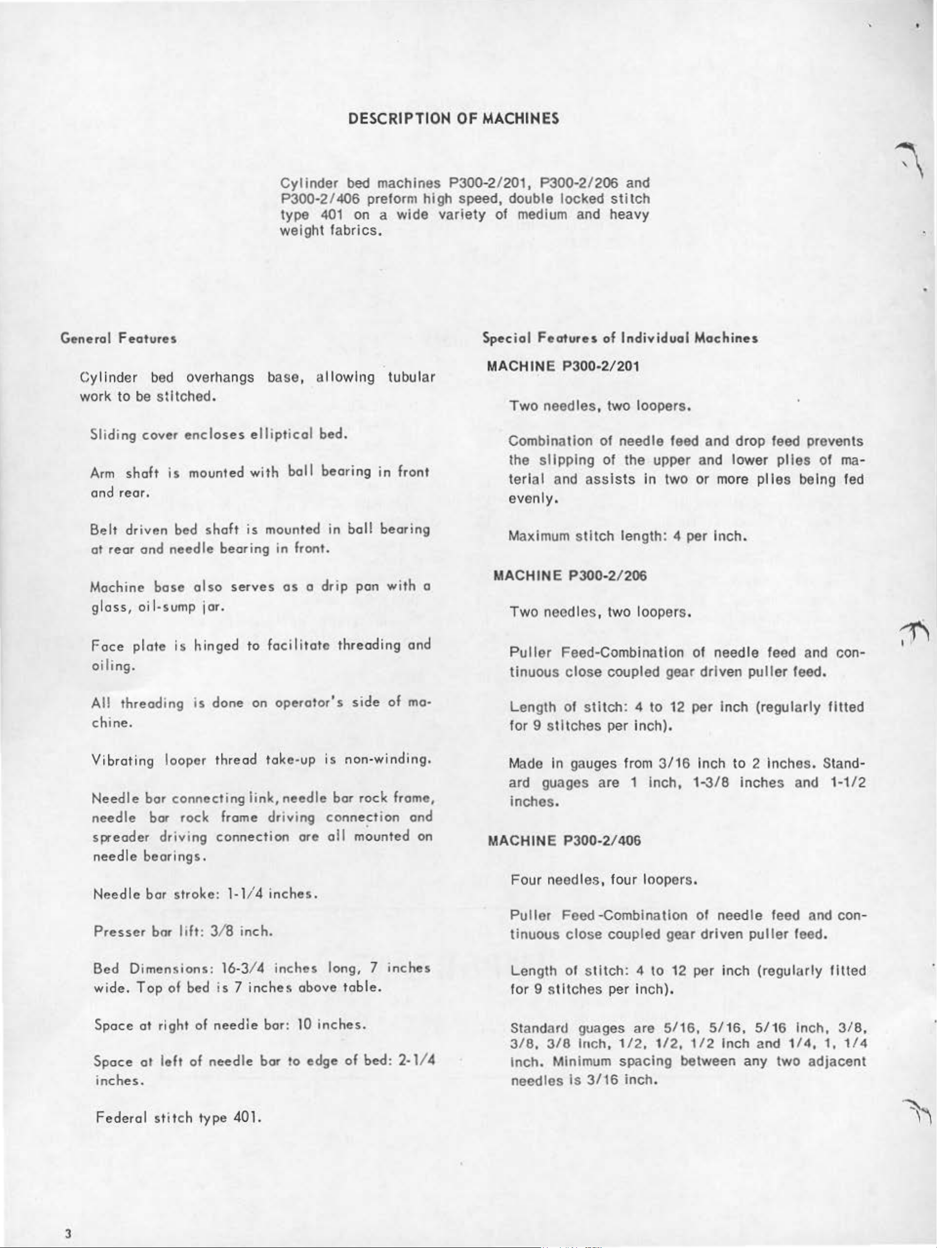
Fig.
2;
/.
I
23.
FEED LIFTING
ROCK
~·
SHAFT
~
~
'---.
71
I " '
~
lL
:
Cl
,
~
~
'
. )..
\
SLIT
"
-
:\
"'
Fee
d Bar Height Setting
POSITION
SCREW
I
11
lL
J.
li
"'
(.l
11
11.\
1=
~~~
''
!J
'-
TIMING
FLAT
FEED
BAR
When
the f
flat
feed l
the rock shaft spot correctly
a
feed I
on feed
If adjustment is required, first
Th
lig
n sl
HEIGHT
feed bar
eed
lifting
lift
ifting
en loosen feed l
ifti
rock
it
of feed
ng sha
SETTING
is
crank
ing rock shaft as shown In
shaft
lifting
ft.
Re-tighten crank pinch screw.
at
P300·2/
correct height, the
Is
aligned
crank position screw engages
•
ift
ing crank pinch screw and
crank
with
201
with
be
the timing
Fig
sure that the
timing fl
slit
. 23.
at
In
on
FEED
DOG
Lengthwise Setting
ADJUSTMENT
P300-2/
201
.
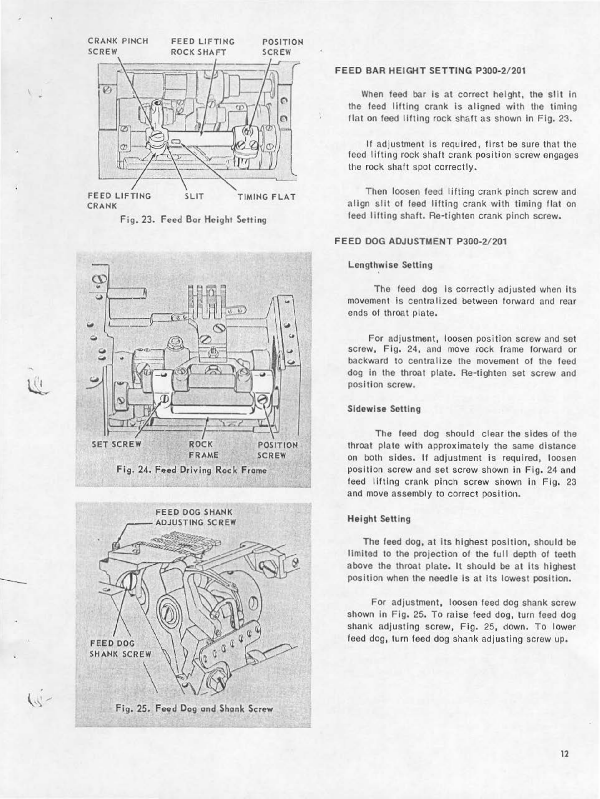
The feed dog
movement Is centralized between forward and rear
ends of throat plate.
For adjustment, loosen
scr
e
w,
Fig.
b
ack
ward to centralize the movement
dog in the throat plate. Re-tighten
posit
Sidew
ion screw.
is
e Setting
24,
and
is
correctly
move
adjusted
position
rock frame forward
screw a
set
wh
of
the feed
screw
en
nd
Its
set
or
and
SET
SCREW ROCK
FRAME
Fig.
24.
Feed
FEED
,---ADJUSTING
Drivi~~
DOG SHANK
w
SCREW
POSITION
SCREW
Rack Frome
Q)
..
J
The f
at
thro
on
position
feed l
and
He
limited
above the throat
position
shown
plate
both sides.
ifting
move
ight Setting
The feed dog,
to
For a
In
eed
with
screw a
crank pinch screw shown In
assembly
the projection
when the needle
dju
stment, loosen feed dog shank screw
Fig
. 25.
dog should
approximately the
If
adjustment
nd
set
screw shown
to
correct
at
its
highest posi
of
plate.
To
It
is
raise feed dog, turn feed dog
clear
is
posit
the
should be at
at
its
the sides
same
requ ired, loosen
in
Fig.
I on.
tion,
full
depth
Its
lowest position.
of
distance
24 and
Fig.
should be
of
teeth
highest
the
23
FEED
SHANK SCREW
DOC
Fig.
25.
Feed
Dog
and
Shonk Screw
st
shank adju
feed dog, turn feed dog shank
ing screw,
Fi
g.
25, down.
adjust
ing screw up.
To
lower
12
Page 3
,·
\
LOOPER
TIMING
FEED
LIFT
The feed lifting
be
adjusted
remain be low the
trate
looper
s the
It
is
driv
lubricating
on
Fig.
Set
26.
screws,
to
permit the
materia
correctly
ing
crank lines
pod on
accessible
throat
l.
the
driving connection,
ECCENTRIC
eccentric
teeth
plate
adjusted
when the
up with
feed
lift
ing
through hole in
allow
for
(P300·2/201
shown
of
~he
in
Fig.
feed
26
dog
con
to
until the needle pene-
edge
the
edge
eccentric
of
the
of the
os shown
feed
adjustment
when re-
LOOPER DRIVING
CRANK
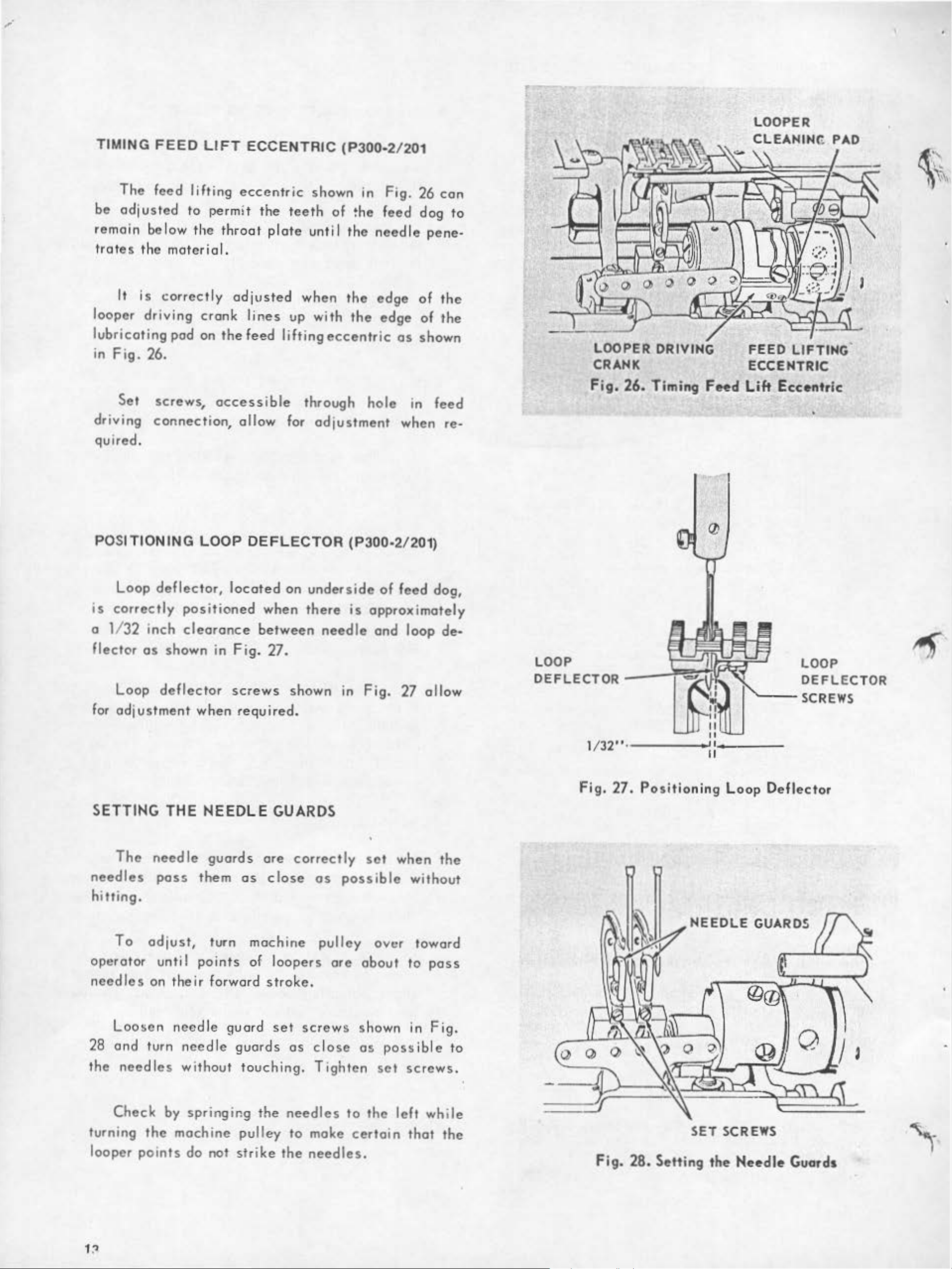
Fig.
26.
Timing
FHd
FEED
ECCENTRIC
Lift
LIFTING.
Eccentric
•
I
•
quired .
POSITIONING
Loop
is
correc
o
1132 inch
flector
Loop
for
adjustment
deflector,
tly
positioned
clearance
os
shown in
deflector
LOOP
located
when
DEFLECTOR
on
when
between
Fig.
screws
27.
shown
required.
(P300·2/201)
underside
there
is
needle
on
Fig. 27
of
feed
dog,
opprox imotely
and loop de-
allow
"---
LOOP
DEFLECTOR
SCREWS
SETTING
The
needles
hitting.
To
opera
adjust,
tor unti I points of loopers
needles
Loosen
28
and
the
turn
needles
THE
needle
poss
on
their
needle
needle
without
NEEDLE
guards
them
as
GUARDS
ore
close
turn machine
forward
gua
stroke.
rd
set
guards
touching.
correctly
as
possible
pulley
ore
screws
os c l
ose
Tighten
set
when
without
over toward
about
shown
as
set
to
in
possible
screws.
the
pass
Fig.
to
Fig.
27.
Positioning
Loop
NEEDLE
Deflector
GUARDS
Check
turning
looper
by
the
machine
points
springing
pulley
do
nat
strike
the
needles
to
moke
the
needles.
to
the
certain
left
thot the
while
Fig.
28.
SET
Setting
SCREWS
the
N ..
edle
Guards
Page 4
5/8"
___
L
__
__
T
__
_
ADJUSTING
T
he
need
be
adjusted
thread
increase
drown
the
NEEDLE
le
thread
to
incr
ease
at
the
top
amount, l
THREAD
toke-up
or
of
oosen
and
decrease
the
TAKE-UP
thread
the amount
need
le
thread
bar
guide
stroke
take-up
may
of
. To
set
NEEDLE
THREAD
TAKE-UP ·-H-._!_
SET
SCREW
GUIDE
SCREW
THREAD
GUIDE 1
-----
-----~-
'
-
1/2"
screw,
screw
reverse
raisi
For
be
screw
shou
bottom
ADJUSTING
TENSION
F i
and l
ng the
overage
set
os
ld
be
of its
g.
the
with
shown
set
RELEASER
29,
and
ower
ad j
ustment
guide.
sew
upper end
with
hold
er.
NEEDLE
ro i
se
guide}.
by l
ing
conditions,
in
Fig.
the
lower
THREAD
take-up
To
decrease
owe
5/8 inch above
29.
end
(or l
ring
The
1/2 inch
the
the
thread
gui
oosen
the
amount,
take-up
de
the
tok
be
low
gui
de
or
should
gui
de
e-up
the
'
~
·
TENSION RELEASER
PLATE---~
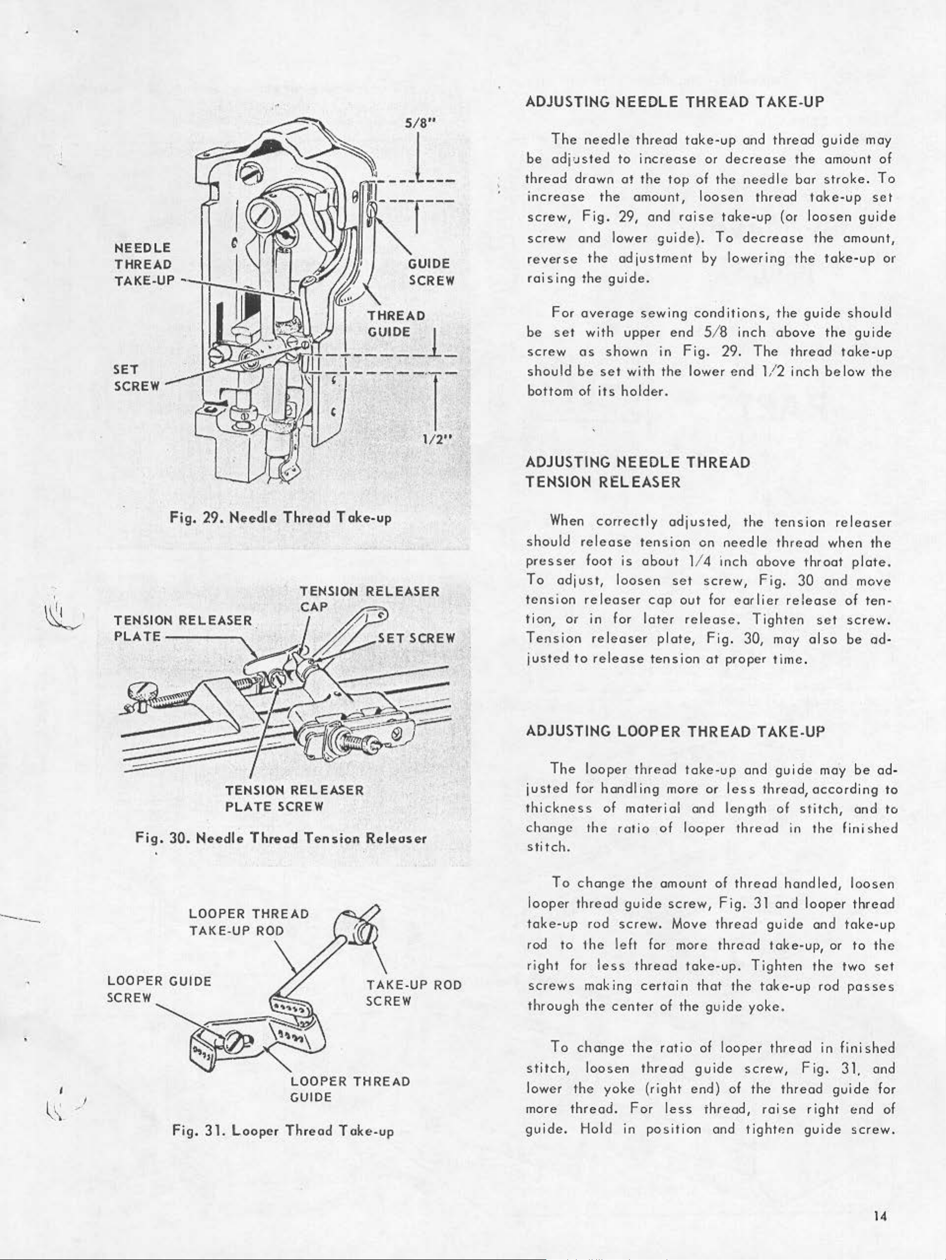
Fig.
29.
Needle
TENSION
PLATE
Thread
TENSION RELEASER
CAP
RELEASER
SCREW
Toke-up
SET
SCREW
When
should
presser
To
tension
lion,
Tension
ADJUSTING
j
thi
adjust, loosen
or
j
usted
The
usted
ckness
correctly
rel
ease
foot is
releaser
in fo r
releaser
to rel
looper
for
handling
of
adjusted,
tension
about
cop
later
pl
ease tension
LOOPER
thread
mater
114 i
set screw,
out
release.
ate,
THREAD
take-up
more
ial
and length
the
on
need
nch
for
earlier r
Fig. 30, may a l
at
proper
and
or less
tension
le
thread
above
Fig.
elease
T i
ghten
time
TAKE-UP
gui
thread,
of
rel
when
throat pl
30
and
set
so
.
de
ma"y
acco
stitch,
easer
the
ate.
move
of
ten
screw.
be
ad
be
ad-
rdi
ng
and
-
-
to
to
----
•
Fig.
LOOPER GUIDE
SCREW
30.
Needle
LOOPER THREAD
TAKE-UP
Thread
ROD
LOOPER THREAD
GUIDE
Tension
Releaser
TAKE-UP
SCREW
ROD
c
hange the
stitch.
To
change
l
ooper
t
oke-up rod
rod to
r
ight
screws
th
rough
stitch,
lower
more
thread guide scr
the
for
making
the
T a
change the rat
loosen
the
thread.
rot io
le
less
cente
yoke
of looper
the
amount
ew,
screw.
ft
thread tak
certa
thread
Fo
Move
for more thr
in
that the
r of
the
gui
io of looper
guide
(right end} of the thr
r l
ess
th
thread
of thread
F i
g.
thread
ead
e-up.
de
read
in
hand led, loosen
31 and
guide
toke-up, or to
Tighten
toke-up
yoke.
thread
screw,
, roi
looper thread
Fig.
ead
se right
the
and
the
rod
in fini
guide
finished
toke-
two
posses
31. and
shed
end
up
the
set
for
of
Fig.
31.
Looper
Thread
Toke-up
guide.
Hold
in
posit
ion and tight
P.n
gu
ide
screw
.
Page 5
NOTE:
When
ordering replacement parts from
this
catalog, a
"P"
prefix must
be
added to
all
part numbers required.
FORM
(365)
P21367
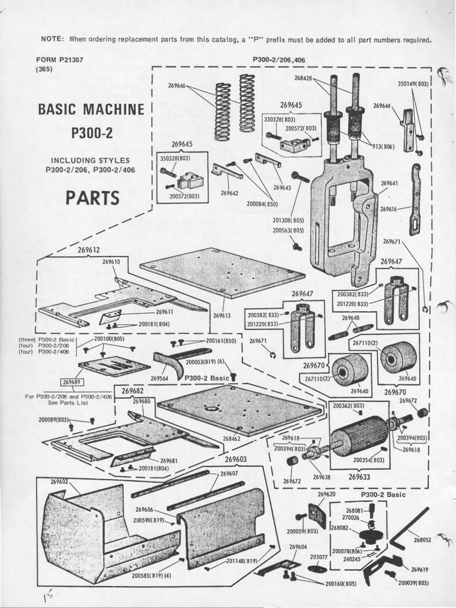
BASIC
PJ00-2
INCLUDING
P300·2/206,
PARTS
/
/
MACHINE
STYLES
P300·2/406
/
/
/
/
/
269612
P300·2/206
~------------------~
I
I
269645
I
350328(
803)
I
..l2005721~
1
269645
~
:
350328(803
)
l~tb
269642
200084(
850)
2013108{
200S63(
\.
)
I
200S72(803)
,406
269644
269641
•
80S)
80S)
269671
269610
•
•
-
•
269647
201220(833)-
":/'
-,
"'"'
'
• • •
• • • •
•
..
-r:
\
~-
169618
J,'-
-2691·3_8
r
~:
-2~3~
P300·2
-26-808-1--::.'
270026
- - - J
Basic
..,
2680S2
-
~
.
I
,
~
~
2000S9(
269619
803)
Page 6
'
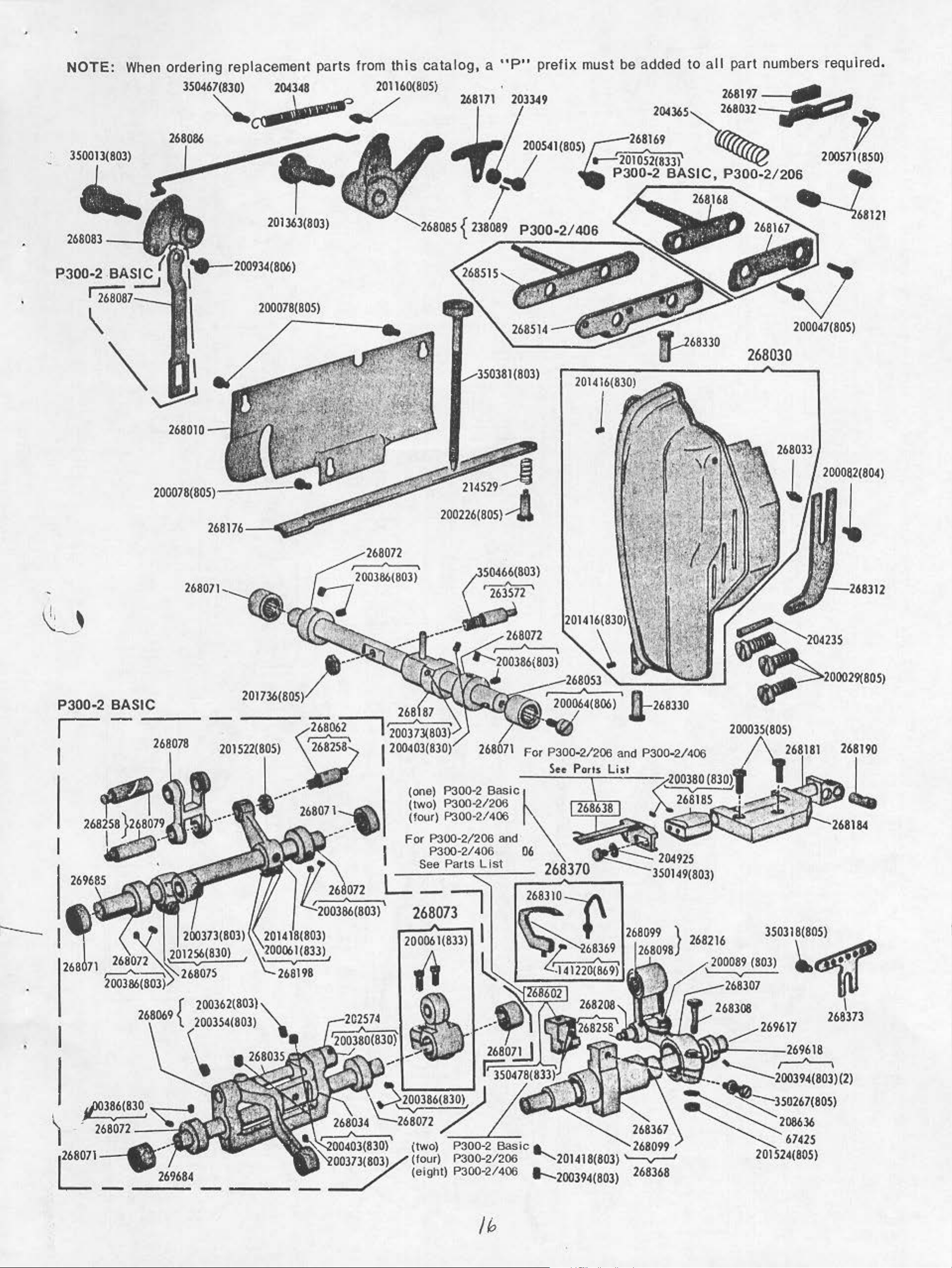
NOTE:
350013(803)
268083--
P.
300·2
I
When
BASIC
ordering replacement parts from
350467(830)
204348
~~../'
201363(803)
1
200078(805)
this
201160(805)
catalog, a "P"
!__..-3:10381
(803)
prefix
must be added
204365
~68330
to
all
part numbers required,
200571
268030
.,
(850)
P300·2
I
I
BASIC
--
268010
268071
268078
----
201
522(805)
200226(805)--!
For P300·2/206 and P300-2/406
See
Ports
200082(804)
L
ll-268330
200035(805)
268190
List
•
I
(one) P300·2
(two) P300-2/206
(four)
For
I
1"300·2/406
1"300·2/206
P300·2/406
See
Parts L
Basic
and·
06
ist
f~~L--,
~2c
(833)
268073
,..--J..__,
200061(833)
I
I
..
268638
l
350318(805)
268216
268308
I~
) .
r807l
268072
-
(four) P300·2/206
(e
-
P300·2 Basic
ight) P300-i2/406
/h
a.
......._201418(803)
..._
200394
(
803
)
268367
268099
'--v--'
268368
67425
201 524(805)
Page 7
~
"
"
"'
.
iL
"'
w
1-
0
z
..
'!l
E
'
-
I
L
•
•
•
.
/"'-
-
-
-.._
,
I
.
·
~
.
iL
"'
Page 8

'
NOTE:
When
ordering
replacement
paris
fron,
this
catalog, a "P"
prefix
must be added to all part numbers required.
j
·
~
'5
rj
MIJMitU
1454(806)
DUCRII'TIOH
Pressor
Pinch
2102 M•ecUe
Dloc(2)
C.to1ot
3260
H...tlo(62a57)
22
asn Arm
10148
32572
50014(803)
SOJ26(803)
51S70(10ll
54279
59537
59538
59539
67425
131T41
141220(869)
20000 4(80
200029(805)
200033
(819
200035(805)
200047(804)
200047(805)
200053(119)
200054(803)
200058(803) H
200059(803)
200059(803)
200064(806)
200069(803)
:j00070(803)
200078(805)
200082(804)
200089(803)
200089(103)
20009
.5(
a 19)
200100(805)
200123(104)
Loa,.,
Spring
Needle
Releosi
He•dl•
Needle
Stud
Heedl•
Thvmb
H••dl•
Th.r•od
H•edle
Sp~ln•
Heedle
SfWIIIg
Needle
Stod 503:16(803)
51570(803)
Loop.r
Clamping
Wo.her
Ne•dle
Sp.fng
Heedle
S)
Ar"" Screw(<4)
Ann Head Screw(3)
)
Bed
Sc
Spreoder
Scrow(2)
Arm
&•oring
Scr•w(l)
Heedle
8reclcet
Bed
Looper
Clo~r~p
Otlvlng
Scrow(2)
Looper
(on
Sc,..w
L.oop.r
(on
Screw
Looper
wp
He•dle
Stu.cl
Pr••••r
8roc:ket
ArM
Scrow(l)
Heedl•
Screw(l)
Sod
Screw(:Z)
Looper
Hinge
N"dl•
Link
Tltreoot
H••~ll•
Driving
Scr•w
..
rew
dle
Bed)
S.cl)
Rod
NUMERICAL
Fool
Shank
Screw
Thr
Position
Thteod
Threocl T
"9
Set
Threod
Th
Nvt
lhreod
tuJd•
Thr•od T ena
Bwahlng
Thteo4 T •naion
Bvddng
Thread
Conler
Thteod
Gvorcl
Side
(2)
Shah
(bock)
Thread T en•
Screw(
Plate
Throod
Screw(4)
&or
Arm
Thr•od
T.,reod
Thteod
S.t
8or
Pinch
Bor
Pinch
Side
Thread
Ploto
Conlet
Pin
8or
Cop
Plot•
8or Rock
Conn.ctlon
(P300-2
.. d Tonalon
51&o
Pln(2)
Tension
en•ion
01
ac
Screw
Tenafon
Tension
reod
T•nalOf'l
(do
...
(front)
(bock)
Tension
wit!>
Cronic
Stud Nut
Tension
S.t
Cover (back)
(P300-2
Bor
BeorlnSJ
Boll
Housing
2)
Scrow(6)
Tvb•
Rock
Pinch
Guide
(on
front)
Guide
(un.d•r
Co"•'
cover)
Tak•·
Scre-w
Connecting
S<:rew(2)
Guld•
Screw
Guide
(loft)
Cronic
Pinch
Connecting
Wnher
Scr.-w
Sc•ew
Ho.
ble)
iOf'l
Scre-w
Basic)
lon
From•
Scr•w
Frome
Cop
LIST
OF
PARTS
HUMBER
:1)0
160(805)
Bast
c)
200161(850)
200173(804) H
200181(804)
200226(805)
20030:U19)
200327(803)
l')0328(8J£1 )
200337(803)
2003~4(830)
200346(803) H
200354(803)
200362(8C3) Loop41r
200364(803)
200364(803)
200364(803)
200373(8031
200378(803)
200380(830)
200380(830)
200382(833)
200386
(80
3)
200386(803)
200 39 4(
80
3)
200394(803)
200403(830)
200541(805)
200562(805)
200S11(8SO)
200572(806)
200573(80~)
MACHIN.
ES
DE5CRIPTI()oj
Sod
(olllptlcol)
Co"'••
Screw(
Ed,.
felt
Bed
Guord
Pre
S"'pport
Looper
Oil
Machine
Scr
M.o
Poairion
He•dl•
Fu;~me
st
L.oop41r Drivi"O Cronk
Position
Set
Heedlo
Positlun
S.t
H
Frome
C"p
Spreader
fcce.ntric
bnl
Spreader
Eccentric
Spreoder Orlving
Cronk Poa
Needle
Position
Screw
Preuer
Collar
Spreader
Guide
..
dle
Holder
Plate
••••
Hole
ew
chi
-no
••
".
..
dl•
Screw
Screw
.. dle
S•t Screw
onco
Lock
2)
Screw(2)
Spring
Screw(l)
8or
Ollin9
Sc:ru.{:2)
(left)
Bot
Sprint
S.cr•w
Dr l
v•no
Co"•'
P"'ll•r
Pvlley
Screw
Oor
Rock
Regulottng
Set
S<:r
Screw(l)
Sor
Cronk
6or
Crou"
Screw
Drlvln~
Sor
Rock
Re\lulatlr~v
Driv
Covnt•r·
~et
Sc,.w'(l)
Driving
Set
1tlon
Bar
Cronk
Screw
Bor
Set
S<:rew
Hold•r
~
Cronk
S.cr•w
Set
Stud
ew
Cronk
Stud
ing
Screw(2)
Scr•w
Check
Stop
Set
5crow( 2)
Heed1e
Frome
Ecce-ntric
Oi.c
S•t
Bed
Colla•
(P300~120G
Spread•r
Shoft
Screw(4)
Loop41r
Collar
Looper
Shoft
Screw
Spreoder
Cronk
Needle
A:el•oaing
Looper
Brocket
fou
Spring
Pres
&rocltet Adlu•ting
Screw
Loop•r
Oil
8or
Ro-e:k
Dri ving
Adjwsting
Spring
Screw{2)
Shall
Collar
S.t
Set
Plot•
sef
Stop
Col
Thrust
Set
Screw(2)
Driving
Corrler
S.t
Screw(
Corrler
Screw
Driving
Screw
Thread
Plote
Ttweocl
Screw(2)
Lock
Screw(:Z)
Bar
Driving Cronk
Scr•w
lor
,
406)
Set
S~ft
Check
Ten•lon
Tens ion
Gui
de
Rock
2)
Sctew
P300-2
HUMBER
200578(850)
200583(803)
200585(819)
200590(819)
2009
Basic,
07
(819)
OE5CRIPTIOH
Loop.r
(top
Suew(2)
.... die Bor
Frome
Screw(2)
Sed
Slide
Bed (elliptical)
Section
(upper)
Loop
Screw(2)
200934(806)
Poot
L.ink
200987(819) L..oop•r
Stud
201020(805)
201052(833)
201148(819)
20 1160(
20118~803)
80
201254(8031
20125.(803)
Spr•od
Connection
Sc.r
Heedt.
Releuur
Screw
Bed
S.ction
(lower)(2)
5)
foot
\prini
Hc.edle Threocl
(on Heedle
Conne>c:ting
Set
Arm
Oeh
Screw(:Z)
Bed
B•lt
Screw(2}
201363(803)
H
201416(830)
201418(803)
201
522(805)
Face
Scr.w(2)
Looper
S.t
Need
c~nnection
....
201524(805)
201572(819)
201736(805)
202005 Arm
202120
202253
202330
203077
203349
203759
204235
Looper
Spr•ad
Shah
Li
lum
8eh
Stud
P300-2/206
Threod
of
Arm)
Btodtet
Rock
Threod
(elliptical)
Bor
Screw(4)
(front)
Dell~ctor
(P300-2
Lift
er L.l
Hinge
er
ew(l)
(elliptical)
Lifter
Screw
~hoft
Pulley
Shoff
Pulley
Foot Lift
in
ge
Plate
Screw
le Bor A:od::
Frome
Looper
Clotn
pinog
Thumb
Scre-w Stu.d
Screw
Foot
Lifter
nk
Stop
S
..
Pul1•y
Flon\)e{2)
Needle
Oil
Bed (•lliptlcol)
Lock Spring
Woahor
Needle
Releosino
Woaher
Pt••s•r
Colla,
Arm
Heod
Screw
Thread
Driving
Cop
Thread
Cop
(front)
L..ev•r
Sc:rew
8or
S
Connection
Set
Connection
S•t
er
Lever
Scr•w
Hinge
Carrier
Dtl'l
lng
Hlno•
Carrier
Stud
Thr•od
Hut
er Driv
Wosher(4)
Llfling
Pin
oh
Conn
Spting
Bor
Conn•ctinv
Pocking
Threod
Plote
Bor
with
200380(830)
Position
£ye
u~oJ)
Screw
Stop
AND
Guide
Guide
Cover
CovM
Screw
Basic)
ftinv
T•nslon
T•nsion
Set
Cov•
Screw
Guide
Set
Shaft
Stu.d
Cronk
Nvt
Tension
ing
Rock
Hut
ection
(wid.)
Cover
Tension
~crew
P300-2/406
HUMBER
204348
204365
204925
204925
206335
208636
214529
214529
2260
226206
228448
238ll89
2
41763
2~•048
263572
264709 H
267623
267669
268003
268004 Arm
268005
268006 Arm
268008
268009
268010
268024 Arm
268024
268028
2611029
268029
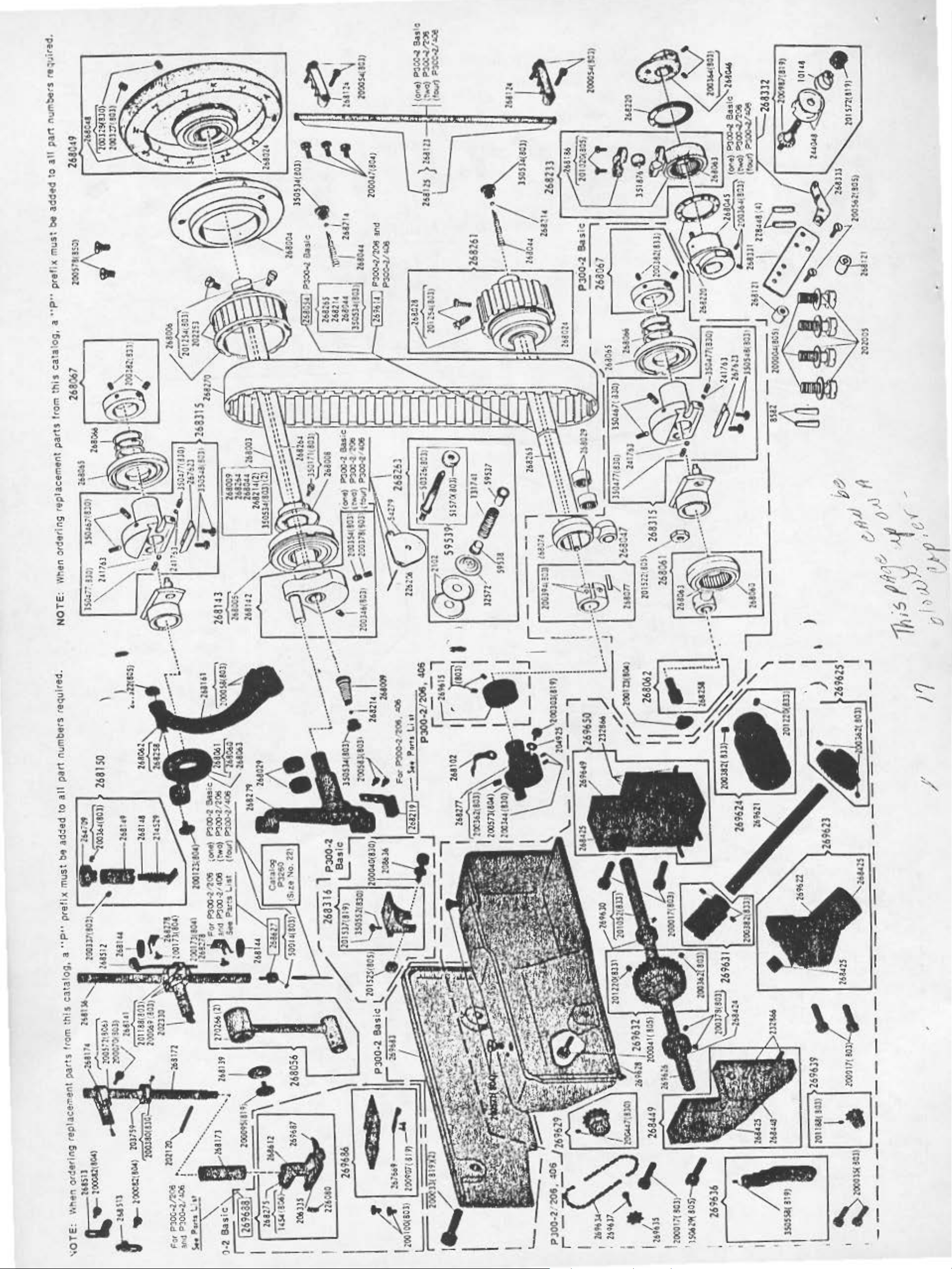
268030
Pin
2611032
80
DESCRIPTION
Foot
liher
Spring
Heedle
R•l•••••
Loo
per
Oil
Hole
Washer
Sp
reader
Pressor
Pin
(P300-:1
Looper
Woahor
H
..
dfe
Fro"M
Stud
Spring
Pr••••r
Cvahion
Pressor
Spring
He•dle
A:eleo.ainv P in
Machin•
Lever
Thteocl
Sptlnt
Dtl
vlnt
Co,..•
Scrow
Fool
Holder
8or
Rod
Revwllllng
lor
Spring
Spring
Fool
(P300
Threod T enaio
Locating
(4)
Needle
Aeleuing
H
..
Dti"lnt;a
Friction
Set
(b.o
L.vope1
Di 1.c(2)
Spreader
Shah
Pocking
..
frnme
Cop
Needle
Driving
Friction
Loop
(P300
Arm
268009.
268264.
2682
(bock)
Arm
(
ftont)
Belt
ooch
Thread T ensio
Plot•
dle
&or
Rock
fcc•ntrlc
Plote
Screw
u )
dle
with
Poclunt
(2)
Thread
Driving
Scr•w
Stvd
(wick)
Bor
Rock
R•gvlotln;
200364(803)
Bor
Rodt
Eccentt
Plot•
Defl
ect
-2 t3ns
Shoft
with
2680+'.
twe; e
14 ond
Shoft
Shaft
Shoh
Pviley
20
350534(803
Boll
Hou.lng
Boll
Connection
with
125.(803)
202253
Arm
S.,oft Oil
with
350171(803)
Arm
Shoh
Boll
Arm
Sid•
Shoft
B.oring
Bed
~hoh
Beoring
8ed
Shoft
S.h
011
Spring
Pull•y with
(front)
Covef
Boll
(bock'
Boll
Connection
20125<1(803)
Bed
Shoh H ..
Beoring(l)
Hoedle
H
..
foce
268033
cllle
Plote
Bor
Rock
8eotlne(
with
ond
two
201416(830)
face
Plate
Lock
Tenai
Ctonlt
Screw
Wast
..
tinge
Basic)
Set~
Plate
-2
Basic
Pin
Fron
Screw
T•n•io
Rock
Oil
•c
or
I c )
och
6eorins:
Beorinc
lwo
Sling.,
Stop
two
dle
2)
Spring
N
Stv•
Stud
Fro
~n
ond
fralfteo
.
!9
Page 9

NOTE:
When
ordering replacement parts
from
this
catalog, a
"P"
prefix must
be
added to
all
part numbers required.
NUMBER
268033
268044
26804S
268046
268048
268049 Machine
268052
268053
268054 Bed
268056 H
268060
268061
268062
2611063
268063
2611065
268066
268067
268071
268072
268083
268085
268086
268087
268098
DESCRIPTION
Foee
Arm
Boll
S.d
Boll
Spreader
Eccentric
200364(803)
Spreader
Ec:centrlc:
balance
l00364(803)
Mochine
(aluminum
costing)
(outside
~oove
200327(803) ond 268125 Lool)4'r Threcrd
200328(830)
with
Looper
Rod
Spreod•
Shoft
Link with
270266
,..
Needle
Frome Driv i
Connection
Needle
Frome
Connection
with
Needle
FroMe
Connection
Stud
Needle
Frome
Connection
Be
Spreader
Connect
Bearing
Needle
From•
Eccentric
Oi
Needle
Frome
Eccentric
Disc
Needle
From•
Eccentric
Disc
with
Spreodttr Dri
Rock
Beor
Spreoder
Shaft
200386{803)(2)
foot
238089
Foot L lfter
Foot Lifter
Link ( P300·2
Looper
Plate
Shah
Sptlng
Shaft
Spring
26802~
with
Shaft
268044, 268214, 268142
268265, 350534(803), 200346(803),
(P300-2
..
dle
268063
Orlvfng
with
Driving
orin;
Orivino
sc
Spring
Drivi
Sprin9
two 200382(833)
Shah
ino(2}
Collar
Foot Lifter
Lifter
Cotmectlon
Lock
OH
(rear)
011
Driving
with
Driving
Counter·
with
Pulley
alloy
for
diam
2. 9 in,)
Pulley
Thread T oke·up
Driving
200064(806)
with
8aslc)
Bor
Connecting
two
&or
Rcxk
ng
Bor
Driving
8or
268258
Bor Rock
Needle
Driving
ion
Needle
Bar Rock
Adiu•tlng
Bar Rock
[)d,.ing
Adjustin~t~
Sor
ng
Ad j
Needle
Driving
Driving
St'ud
Stop
Stop
two
two
"V"
belt
of
belt
with
2680.48 268136
Rock
Rock
268060
Rock
Hinge
Rock
usting
Collar
ving
Rock
with
two
Bell
Crank
L•ver
Lever
Lifting
with
Rod
Basic)
NUMBER DESCRIPTION NUMBER
268099
268099
268102
268121
268121
268123
268124
268139
268141
2681~3
268144
2611148
268149
268150 H
268161
2681
67
2681
66
268169
268171
2611172
268173 Pr
26817~
268176
268181
26818~
26818S
268136 Spr•Qder Drivi
268137
268190
268197
Loo~r
S.orlng-(2)
Loop•r
Connection
Bearing
Looper
Oil Hole
Loopo~r
Tension
Spacing
Needle
Brocket
Collor(2)
Looper
with
Looper
Clomp(2) 268233
Thr•ad
Needle
Needle
Connecting
Woaher
Needle
Connectin9
201188(803), 202330
ond
Needle
200354(803) ond
200378(803) 268028 wHh
Needle
2611142
Needle B-tu
Felt(2)
Heedle
Frome
Stud
Needle
From•
Stud
..
Fro•
Stud
2US29, 264709, wi
2681~8
Nudle
Frame Dri
with
Needle
S
rack
Need
Rele
Hud
Re
201052(833)
Ne~dle
Releasing
(Adi
Presser
Presser
Brodtet wit
200070(803) ond
200572(806)
Presser
Spreod•r
Spreader
Spreader
200380(830)
Connection
201020(805)
Spreader
Cronk
l00373(803) ond
200403(830)
Spreader
Foe.
SprinQ
Carrier
Driving
Driving
Heedle
Needle
Crank
268208
268214
268214
Cover
Thread
Broc:lt:et
Collor(2)
Thread
Spacing
Thread
two
2681 25
Thread
Bushln~t~(2)
Bar
Bar
Bar
two
200069(803)
Bor
Bor
wHh 268005
Bor
Regulating
Bar Rock
Reouloting
Sleeve
dl•
8or
·ne
R•gulotlng
complete,
ond 268149 (1?300-2
Bor
two 200058(803)
Thread Ten
el (P300-2
le
Thread
aser
le
Thr•od
leour
Thread
ustoble)
Bor
esser
Bar
Sor
Bor Spr i
with
Plate
Plate
Tension
Tube
Tube
Tube
Link
Cop
Stud with
Cronk
Cronk
Oilin~t~
Rock
Rock
Rod
ving
(P300·2.
Cop
Plate
Guide
h
Bor
Bar
Holder
with
Drivi
Orlvlf'g
Lock
with
e
Arm
Basic,
Tension
Tension
wl th
Ten•ion
Bushino
ng
Bearing
with
ng
two
ng
Pfn
Basic,
268216
268219
268220
2682S8
268258
268261
268263
268264 Arm
26826S
268270 Arm
268Z75
268277
sion
268278
200)
268279
206) Frome
268307
263308
268310
268312
268315
268330
268331
two
'
268332
268333
268367
268368
DESCRIPTION NUMBER D!SC:RIP'TIOM
Looper
Crank
268258
Arm
Boll
Bed
Ball
LoojM'r
Corrler
Hinge
Shah
sn2
Shah
S/32
Driving
Pin
with
011
Stop
in,
diom,(2)
Oil
Stop
in, diom.
268369
268370
268373
Leo,.,
Loo..-r
Guard
261310 on4 268369
Loo.-
(on
wltl.
....
Needle
CtMftplete.
Tlweod Golde
Bed
at
L..,.r)
141220(169)
Connection 268098
with
268099
Neoo
(P300
Spreader
Wosher(2)
le
Bar
Rock
Frame
Eccentric
Spreader
Connection
with
351876
Looper
Hinge
Pocking
He•dle
Frome
Connection
Stlld Oil
(w
Bed
Belt
Needle
T.,nsion
32572, 59537,
59538, 59539,
1317
Rod
Bed
Rod (wood)
s.lt
neopre
Pressor Foot
Looper
Cra,..k
200573(80.4)
200344(830)
Ne•d
Felt
He~dle
Looper
with
Looper
Clamping
Needle
Nudle
(on
Need
Fro~
with
241763. 350467(830),
350477(830)
350548(803)
Face
Stod(2) L
Looper
Bracket
Looper
complete,
200987(819).
201572(819)
244048
Looper
Thread
Looper
Looper
268367
268099
Thread
-2 BasiC)
Driving
Thrust
Driving
268063
Corriet
Pin
(wick)
Bor Rock
Driving
Pocking
iclt)
Shaft
.. 1 ond
Shah
(wood)
Shoft
Shoh
th
Arm
Connectior'
Pulley
Thread
complet•,
Oil
(reinforced
ne)
1454(806)
Basic}
Orlvi.ng
with
le Bo r
Holder(2)
Bor Rock
Co,ier
200089(803)
CarritH'
Stud
Guard
Thr.,od
Head)
le
Sor
Drivi
267623,
Plate
Thret'ld
Thread
10U8
Thr•od
Guide
Cartier
Corder
with
Guide
268186
ond
Cronk
011
Hin99
26802~
two
2102
Oil
Control
Control
Conhection
Shahk
200362(803),
and
two
Oiling
Cronk
Cronk
Guide
Rock
ng
Flange
two
•och
ond
Hing•
Tension
Tension
and
two
T..,sion
two
268462
268512
288513
268514
268515
268602
268612
288627
268638
269564
269602
269603
269604
269606
269607
269610
269611
269612
269613 Oed
2696 14
269615
269616 F
269617 Looper
269616
269619 L ooper T
269620
269680 Bed Plate
269681
Boo
Plate
(P300·2
Needle
(on
Need
Connecting
Needle
(on
side
Need
350478(833) (P300·?.
Spreader
le
Br
acket
Neoole
Releas~
Looper
Pr
e5sor
Heel
Neoole
50014(803) (P300-2
(P300-2
Bed
Cover
Bed
complete,
200590(8t9),
269610,269611,
Sp,.ng
Edoo Guido
(elliptical)
(elliptical)
269602, 269606,
••
,h
201
269607
200S8S(
Bed
(elllptlcol)
Lock
S.d
(elliptical)
Set::tlon (front}
Sed
(elliptical)
Slide
Bed
Plate
(P300·2/206,406)
Bed Plat
(P300·2/206,406)
Bed Plate (left)
Guord compl
two
200
(P
300-2/206,
Plate
(
P300-2/206,
Bed
Shall
268044,
2~6265,
(P300·2/206.
Bed
Shaft
Collar
200386(803).
(P300·2/206,
oot
ink
Loopet
Colla
200394(803)
(on
Bed
(right)
Basic)
Thread C'-..lde
le
Bar
Stud)
Thread Gui
of
Am1)(2)
Thread
(P300·2/406)
Thread Tension
r
(P300-2/406)
Holder
Foot Plate
(P300-2
Holder
with
Basic)
with
Lock
148(819),
ond
fow
819)
Spring
Bcu(2)
(left)
e (l
eft)
ete,
161 (804)
(right)
with
268214,
350534,(803)
Thrust
with
two
Lifter Lifti
(P300-?./206. 406)
Carrier
Carr1er
r w i
th
two
hread Gui
) (on front)
Looper Thread Guide
(on Bed) (under cover)
(left)
(P300-2 Basic)
Bed
Plate (left)
(P300·2
Basic)
de
Tension
with
with
Point
Stud
C-ovet'
two
Cov"
Cover
Cover
Guard
and
and
406)
406)
406)
406)
ng
Shaft
Shaft
de
Guard
,
'
two
Basic)
Basic}
Basic)
,
'
_____
i' 268044
·
~
•
~
lq
Page 10

'
•
NOTE:
When
ordering
replacement
parts
from
this
catalog,
a
"P"
prefix
must
be
added
to
all
part
numbers
required.
I
IIUMI!R
269682
289683
269687
269688
DUCRIPTIOII
Bed
Plate (lefl)
<>uard
269680.
complete.
269681
r.nd
and
two 200181(804)
(P300-2 Basic)
Bed Side Cover (back)
(P300-2 Basic)
Pressor
(P300-2 Basic)
Pressor Foot (spring
hinge
ne
ed
206335.
268275,
269687
Foot
Plate
d)
complete.
lc
hOI
e,
226080
.
268612
( P300-2 Basic)
40
and
HUMIIER
269689
270266
350013(803)
350149(803)
350171(803)
350267(805)
350318(805)
OESCRIPTIOH
Throat Plate.
269686 (
Heedle
Connecting Link
H
.. dle
Foot
Cronk
Spreader
Arm
Sllnoer Set
\..OUjMt
Looper
(on
Bed
Scr
ew
PJ00-2 Basi c)
8or
8eoriru~(2)
Lifter
Sl\oh
Bell
HlrulJ•
Screw
Screw
Oil
Screw
Holder
Threod
ot
L.oo~r)
lor
Screw
Guide
HUMBER
350381(803)
350466(803)
350467(830)
350467(830) Pr
350477(830) H
DESCRIPTIOH
Preuer
A
Spteocfet
Rock
Shtcl ""'hh
Heedle
frame
S•t
Adjuatlng
Screw
Frome
Ecc•ntrlc
Plate
Screw(2)
dlntint
Shoh
Bar Rock
Orlvlnt flong
Screw(2)
e•••r
..
dle
Bor
Otiving
Screw
Bor
Spting
Scr
ew
Dtlvlnt
Screw
263572
Bor
Spring
Screw
Rock
Fflc:tlon
Set
Set
HUMBER
350.78(833)
350478(833)
350534(803)
350534(803)
e
350548(803)
351876
DESCRIPTIOH
Looper
Screw
Looper
Arm
Boll Suew
Bed
Boll
Heedle
Frome
Eccentric
Plote
Spreader
Roclil
St~o~d
Adlw •
Set
Shah
Shoh
Oil
(2)
011
Screw
Bar
Orivlng
Friction
Suew(2)
Or~vlna
Shoft
Boll
Roll•r
ting
Screw
Rock
Screw
Stop
Stop
I
STANDARD
4AUGU
l/4"
711''
...
J
,l/
.f'" 2681
l~l/1'"
1/1/2"
l*l/4 ..
:r·
114, 1/.f, u
S/H,
S/16, S/16u
....
FiTTtHGS
LOOPER
HOLDER
26al05
:::;~
,
OL.'.
ROC
I(
FRAME
THREAD
2612$$
8AR
GUIDE
HEEDLE
HOLDER
P3D0-21206
2611S4
I
2&110$
261106
07
261107 241261 2681 S7
260212
261211
2612U
261256
261261
261)04
2611S4
2611 S6
268157
2681>J
-
P3
D0-2/406
26906> 2691lt
269065
26tUI
269191
269192 2692)1
CCOM.PLf:TU
I
FOOT
··~l,·~·
--
269)74
269)74
26U74
269.51'1
269.517
26Un
SPREADER
26&176
26a:J76
268311 269S98
268378
268373 26,611
261178
261179
,..,,.
26tl'l7
2:69).42
2693.42
THROAT
PLATE
»9S97
21696$1
269597
269$91
269597
16tSt1
.
26fU2
-
HUMIIER
:100040(130)
-1(133)
200061(133)
•
200071(806)
200100(101)
J>Oill(SO.)
2003$4(103)
,,
' '-!}' lOOJ62110lJ
J>Ol7l(IG3
200310(130)
lit.
118,
J/1''
1/2,
112,
1/r'
1/.C, I, 1/.C" 269065
26906S
269065
DfSCRIPTIOH
F-.1
Screw
feed
Sftoft
Sc,ow(l)
F •
Shoh
Screw(2)
f••d
Socic•t
Conn•ctlon
)
.ct
f••d
Fe
ed
f•ecf
f'roftll•
fee.cf
Fra-.
feecl
Hlne-t
(2)
F
..
d
C.llar
Dot
5h...,k 200312(133)
Drl•lng
Cronk
L
lftlng
Cronk
R•oulatJno
Scr•w(2)
Ooo
Orlvino
Driving
Pa•ltion
o,a.,lng
S.t
Lifting
Pin
lor
S.t
Roell
Pinch
Rock
PInch
St~o~d
Screw(2)
Cop
Scr•w
Rock
Scr•w
Rock
Screw
Link
Se1
Scr••
Hinge Pin
Screw
2691)11
249UI
2691)1
-
P300·2
HUMBER DESCRIPTIOH
fe•d
Ad
l~o~
• tino
Collor
200386(130) F
200386(803)
200)94(803)
200403(830) F
201256(830)
201411(803)
20\522(805
201522(105) F
.. d Ori.,ino
Shah
Screw(
Feed
Roclc
Set
Screw(
Fud
Set
Scr•w(2)
..
d
Screw(2)
fe
ed
Pinch
F
.. d Lifting Ro.ck
Shoh
Scr
ew
)
feed
Connection
""'
.. d Lifting
Connection
Stvd
Basic
Orl•lno
S•t
Collar
.C)
Llhing
Shoft
Lifting
Bor
Set
Lifting
Scr••
Crank
Driving
Hut
Ecc•ntric
Oi•c
Screw(2)
Roe-k
Set
Collar
.C)
Eccentric
Cronk
Position
Hinge Stud
Hino
269192
269193 269240
26919]
DROP
FEED
PARl"S
HUMBER
201525(805)
Sprino
201
537(819)
202574 F
208636 F
U0245
241763
267623
268034 F
e
268035
26Ul1
269240 269342 269598
169342 2:696$2
2693-42
269~·
-- -
DESCRIPTIOH
Fu4
Screw
A
Do9
F
.. d Ooo
dl~o~
•t ln
Lodt
g
Shonk
H~o~t
Shonk
Scr
ew
H••
.. d Bar
Ca
ll
or
200
380(830)
..
d Dog
Screw
F
..
d
Reuainlng
F
.. d Otlvlno
Eccenttlc
Plate
PQcklno
Feed
£cc•ntrlc Fricti
Plate
.. d 8or
200373(803)
200•03(830)
F
..
d Bcu Hi
Pin
Hlno•
with
Shonk
Washer
Reg~o~luting
Spring
Friction
Screw
Orl•ln~
(bro
with
Set
..
o•d
nge
Lock
Pin
Stud
Screw
)(
2)
on 268063
two
HUMBER
268047
268060 F
268061 F
268062 F
268062
268065
DESCRIPTIOH
F
..
d Llfti
Eccentr
268077
200394(803)
..
d Oriv l
Conn•cllon
.. d Drivino
Connection
wllh
268063
.. d Dd.ino
Cann•ctlon
with
26a2S8
Feed Ll't
Connection
With 268::158
Fe•d
Connect
Beorint
Feed
Ec:nntfic:
Oitc
Orh•lnt
Orh•ino
no
ic
with
and
two
no
268060
Hlno•
ln o
Hino
ion Heedl
Adjustint
Stud
e Stud
e
J.O
Page 11

•
NOT
HUMBER
268066
E:
Wh
DESCRIPTION
Fe•d
Ecc.ntrlc Adj
Oi
268067 F
Ecc
Disc
whh
268069
268071
268071
268072
F
Frome
ond
F
Shoft H ..
F
Shoft
F
Shah
200386(830)(2)
268072 F
Shoft
200386(
en ordering replacement parts from
Orl
vino
.c
Srtrlno
.. d Orlvlno
ent
ric
Acfiuating
Spring
two
200382(833)
nd
Or l
vino
with
200362(803)
.. d Driving
dltt
.. d Lihlno
Needle
.. d D,l.,ing
Collar with
.. d Lifting
Col
lor
803
)(2)
usting
Coilor
Rock
200J54(803)
Rod
e
Beoring(2)
Rodt
B•oring(2
Rock
two
Rod~
with
two
HUMBER DE
268
073
268074
268075 F
268077
268078 F
)
26
8079
268081 F
268082
SCRIPT
f•ed
Shofl
200061(833)
Food
Connection
.. d Liftlno
with
201256(830)
F
.. d Llftino
Ecc
Pod
.. d l..lhino
F
.. d Liftin
Honoe
268258(2)
.. d Regulotino
F•ed
Sock
this
ION
Orlvino
Cron\
L.ihino
200373(803)
erot
rlc
(wood)
Pin wit
Reovlotino
et
with
Cronk
Lubricotint
Li n~
g
Lin~
cata log, a
Roc~
r
....
ond
h
Srud
Stud
o
268198
2682S8
2682~8
2682~8
268315
268316 F
"P"
HUMBER
prefix
DESCRIPTION
F
.. d L.lhlno Roc:\
Shoh
20U18(803)
100061(833)
Food
Connection
011
F..,od L.Htlno
Connection
Stud
(wick)
Fttttd
Hi
Pocld
F
w
241763.
3S0477(83U)
lSOS48(8031
.. d Ooq
101537(819)
3SOS52(830)
must
Pocklno {wic
Cron\
Or
lv l
be
wl m
and
no
Hin
added
two
o•
Stud
k)
Hlno•
Oil
Poddnv
Llhlno Linlc
noe
Pin
Oil
no (
....
lclc)(2)
.. d Driving Flonge
hh
26
7623,
two
eoc"-
3~467(830).
..,4
S.hon
lc with
ond
to
all part numbers required.
HUMBER
269684
26968S
269686
270026
3~467(830)
3~477(830)
3~548(803)
3~552(830)
DESCRIPTION
Feed
Shoft
F
Shah
Food
hole,
ond
•••
Stud
F
S•t
E
Plot•
Scrttw(2)
Eccentric F
P
Adjustint
Orl• l
.. d Lihlno
Dog,
with 267669
two
200907(81 9)
269689
F
..
d Rogu l
Sprint
.. d Orlvlno
Screw(:Z:)
Feed Orlvln
cc
entr
ic Friction
Screw
Ftted
Orl wlnt
late Screw(2)
Fee~
Dov
s.fotonl.
Scnw
nt
40
otlnt
t
ricti
Rodt
Roc"
no•~llo
Flange
'
S.t
on
\
~
P300·2/206,
HUMBER DESCRI
913(806)
200017(803)
200017(803)
20003~803)
20004 1(805)
200084(8~)
200354(803)
Puller F ..
(upper)
A
djustint Screw(2)
Puller F .. d Cross
Shaft
Puller F ..
Shaft
Pvller
(lo
w•r)
Sproclc
Scr•w(2)
Pull•r
Shoh
(lo
wer)
Puller
(upper)
Arm Scre¥1{2) 201220!833)
Puller F .. d Roll
(lowt~r)
Screw
200362(803) Pullll)r
Shoh
S
crew(2)
200362(803)
200362(803)
200378(803)
200382(833)
200382(833)
200382(833)
200394(803)
200447(130)
200S63(80S) P
200571(804) P
Pvller F ..
$t\oh
Screw
Pull•r F .. d Ro
(lo
w.,) Set
Puller F ..
Shoh
Screw(:2)
Puller
Shah
Puller F .. d Driving
Shoh Worm
Screw(:Z:)
Puller F .. d Roll
(uppttr)
Scr
P
vll
(lower)
Sttt
Puller
Shoh
Scr
ull
(upper)
Sc
uw
ull
Shah
(upp ..
PTION
d Roll 200572(803)
Sor
Spri n g ( uppfl'r)
B•ocket
d Otl.,.ing
Brocket
Feed
et
Feed Drlvi
Cover
Fe..d
Fe•d
Worm
Worlft Geor
Collar
Worm
ew(l)
er P .. A Roll
Screw(~)
Sprocltet Set
ew
er f
(lower)
et
Co•e r Screw
Roll
Cho
ln Idle..
6r4c.
Screw
Rol l
Bar
Lifter
Posit
ion
Crou
Ceor
cl
Orivln9
Screw
cf
Driving
Set
Feed
Fe•cl Orl•ln
fe.d Otl
Crou
Set
Set
Brocll:et
Shoh
..
8or
Coll
d
Roll
8rocltet
)(2)
Screw(2)
Screw(3)
lt.t
n9
Set
Set
ll
Screw
S•t
ar
g
ving
HUMBER OESCR1PTIOH HUMBER
Puller
Brodcer Adjusting
Screw(2l
201052(833)
201158(803)
201220(833)
201220(8
33)
201308(80$)
2
32866
232866
267110
268424
Puller F .. d Driving
Shaft
S•t
Puller F ..
(lo
Sproc
Puller
Shah
Screw
Pulle-r
Sho
Position
Puller
(upper)
Position
Puller Ftted
(upre
Screw
Pull•r
Shoft
P
in(2)
Pufl
Shoft
Po•itlon
Puller
(upper) H
a .
Pullet Feed
Sh
200378
268425 P
268425
268428
2684~8
uller
Shoh
8eorln9(l)
Puller
S
hoh
B•orlnvU)
Puller F .. d Roll
(upper)
Pull.,
Shah
268449 Pulltlf' F
S.,_oh
168
269618
269621
Puller
(l
ower)
wloh
Puller Feed
Sha h
Feed
Sor
Thru•t
Screw
wer)
Shoft
litet Set
Feed
Worm
Feed
ft Worm
Fud
Brocket
r)
Bar
(upper)
Fe
Broc
er
Feed
Broc
Ffted
oring(.4)
oh
Collar
(403)
Feed
Httedle
Feed
Heedl•
8or(2)
F~ed
8roclt
..
Brac
448
with
Feed
Shaft
Owo
Screw
Sc:rttw(2)
• d
Pln(.C)
..
200394(803)(2)
406
Roll
Po• i tion
Collar
ct
Roll
Screw
Cro
u
Position
Driving
Gear
Roll
Roll
8rockttt
Cro
n
ket Pos
ket
'CI
with
Otivi"9
et
d OrivinQ
h t
ition
Orivin
Roll
Ie
Dri
Crou
Orl.,.lng
268~25
Roll
Crou
9
ving
two
C411or
PULLER
269622
269623
269624 P
269625
269626
269628
269629
269630
269631
2
6963
269633 Pv
269634 P
269635
269636
269637
26
9638
2o9639
~
FEED
2
I·
PARTS
DESCRIPTION
Puller F .. d Crou
Shoff
Puller
Shoff
whh
Sl-to
200382(833)
Brocket
Feed
Cro
Broclcttt
two
ull•r F .. d Cro
h Woof!
269622
26842.$
whh
ond
n 269641
u
201220(833)
Puller
Shah Wo""
owo 200
Puller
Shah
Puller
Shaft
Pvller
Shoft
2004A7(U
Pulle
Shoh
wioh 201052(833)
Puller
Shoh
200382!833)
9
Pul:er
Sl.oh
200362(803)
Feed
362(803)
Feed
Feed
Cove
Ff!fld
Sproc"et
r
F~ed
Thrust Coll
Feed
Worm
stitches
Feed
WOf"'
Cros
Geor
Otlvln9
Otivln9
r
Otlvlng
))
Dr i
Driving
with
Uo•
per
Dr i
Geor
ond
s
with
with
ving
er
two
inch)
ving
with
2C1220(833) (loo 9
titchu
s
ller
wloh
20
036
uller
flower)
Pu
ller Feed
(
low
Idler Sproc:l..et
Pull"'
(lowttr)
Iefier
Bracket
per
Inch)
Feed
20035~(803)
Roll
(low•r)
ond
2(803)
Feed Roll
Chain
Roll
er)
Chain
Fud
Sproc
Roll
Choif"'
kttt
with
350558(819) A
Pull•r F .. d Roll
(lower)
Sproc
Pvller
(lower)
Puller
(lo
Sprncket
l..et Pin
wer)
Cho
ln
lcll
F•ed
Fu d Roll
Roll
S.hoft
Shah
whh
er
20 1188(803)
HUMBER
269640
2169642
216964J
269644
269645
269646
269647
260648
269649
2696SO
269670
269671
269672
3S0149(80l)
350328(803)
3~SS8(819)
3~29(805)
DESCRIPTION
Puller
Feed
Roll
(uppo•)(2)
Puller F .. d Roll
(upper)
Pull"' F ..
(upper) l
Arm Cl
PuUer Feed
tuppe
rm
A
Puller
(upper)
Arm 81ocll
Puller
(upper)
8ra
200572(803)
eft
r)
(ritJo.t)
Feed
Feed
clcet
Bar
or
)
8or
8or
Bor
with
8roclun
cf
Roll
Lift
Roll
Lift
Roll
Lifter
Roll
Position
ond
er
.,
350328(803){2)
Puller
(vppttr)
Puller
(upp•r)
200382(833)
Fud
Roll
8or
S.,rlno(2)
Feed
Roll
Brocket
ond
with
201220(833)(2)
Pullttr
(upper)
Puller
Shoh
P
Shaft
w
Beor
Puller
(upper)
two
Puller
(uppe
Reta
Puller
(lowe
89oring(2)
Puller F .. d Roll
(vpper)
Puller F .. d Roll
(uppe.r) B
Brocket
Pvller
(fo
Sprocket
Puller F .. d Drl•lnt
Shah
(lower)
Feed
Feed
8roc:ltet
vller F•e4 Orl••n9
Brocket
ith
268~25
in9
26711
r) Shoft
in
inQ R lno(2)
t) S
rm
Oloc\
wet"
) Cfoaln lcller
Brocllet Scr
Roll
Shah(2)
O..ivino
(rioh
269
(
Heedltt
on
leh,
Fud
Ro
ll
2696.40
Fud
Fud Roll
hoh
8-or
ar
Pinch
Feed Roll
Pin
with
0(:2)
Roll
Needle
lifter
Screw(2)
Position
Sc:rew(l)
Set
Screw
ew
,
t)
6~9
'
"
·
~
'
•
II
Page 12

'
BED PINS
MACHINE
BED
CUSHIONS
PINS
Fig.
2.
Installation
' ; .
. .
~
.
,.4--
MACHINE CUSHIONS
MACHINE BASE
''
FCIOT. LIFTER
.
LEVER
OIL
DRAIN JAR
IHST
drain
1 or.
pi
wi
ALLA
Fasten
jar
Set
ns
Connect
th
machine
into
cha
TION
machine
aligned
machine cushions
foot lifter lever
in
furnished
LUBRICATION
These
machines
wi
th
onto
bose
machine
for this
hove
to
hole
on
table with hole
in
table.
bose
as
to
purpose.
automatic oiling
Attach
by i
nsert
shown
foot lifter
for oil
oi l
dra
in
ing
bed
in F ig. 2.
trP.ad le
system
, ;
.
-"
'
Fig.
3.
Foot
Lifter
Lev'er
consisting
shaft
centrifugal
to all
oti ng.
ports
reservoar s.
Oi I
which
princi
holes
in
contact
of
o
oct
force,
ple
bear
ore
hollow
as
reservoirs.
through
ings
provided
which
arm
small
when
ore
shaft
the
for l
not
and
Oi l
jets
machine is oper
ubricat
lubricated
hollow
is
delivered
in
the
ing
from t
bed
shafts,
movab
by
·
le
he
4
Page 13

• •
P486·72
•
Supplement
Parts
Chart
to
Form P21367
SAME
LIST
AS
OF
PARTS FOR
P300·2/201
BASIC MACHINE P300·2 WITH
MACHINE
THE
FOLLOWING
EXCEPTIONS
•
267821
267825
267829
Feed Dog
056).
When
Feed Dog
and
1-1/4"
Feed Dog
with
with
two 268318
ordering
two 268318
state
gauge {code 116).
with
two 268318
and
four 200172(804)
gauge .
and
four 200172(804)
When
and
four 200172(804) 15TPI
orderiug
15TPL
15TPI
state
1146
1146
gauge.
11460
N.H.
for
N.H. for
N.H. for
7/8"
1"
1-3/8"
gauge (code
gauge.(code 100)
gauge
268105
268106
268107
268136
268255
268256
{code 124)
and
Looper Holder
1-1/2"
with
gauge {code 132).
four 350478(803) for
7/8"
gauge.
Looper Holder
Looper Holder
124)
and
Needle
Needle
1-1/2"
Bar.
Bar
Rock Frame Thread Guide
with
with
four 350478(803) for
four 350478(803) for
gauge (code 132). ·
1"
1-1/4"
When
for
gauge.
Needle Bar Rock Frame Thread Guide for
When
ordering state gauge.
gauge (code 056).
gauge (code 100).
gauge (code 116)
ordering
7/8"
1"
gauge (code 100).
state
gauge.
gauge.(code 056).
When
When
1-3/8"
When
When
ordering
ordering
state
state
gauge.
gauge (code
ordering
state
ordering state gauge.
•
268268
268154
268156
269574
269577
268376
Needle Bar Rock Frame Thread Guide for
124)
and
Needle Holder
Needle Holder
Pressor
(code
Pressor
gauge (code 124) and
Spreader
1-1/2"
Foot
100).
Foot
with
gauge (code 132).
with
with
two 50014(830)
two 50014(830) for
(hinged, compensating)
When
ordering
state
gauge.
(hinged, compensating)
1-1/2"
two 268162 for
gauge
7/8"
When
for
7/8"
1"
!146D
1146D
(code
gauge (code 056).
1-1/4"
gauge (code 116)
ordering state gauge.
gauge (code 056).
gauge (code 100).
N.H.
N.H.
132).
for
7/8"
for
1-1/4"
When
gauge (code 056) and
ordering state gauge.
When
When
gauge (code 116)
ordering state gauge.
1-3/8"
When
ordering
gauge (code
state
ordering state gauge.
1"
1-3/8"
gauge.
gauge
268378
267858
NOTE:
When
Spreader
1-1/2"
Throat
ordering replacement parts
with
gauge (code 132).
Plate
two 268162 for
for
7/8"
gauge.(code 056).
from
1-1/4"
When
this catalog, a
ordering state gauge.
gauge (code 116)
~~
When
"P"
1-3/8"
ordering
prefix must be added to
state
gauge (code 124)
gauge.
and
all
part numbers required.
Page 14

'
267859
267860
268382
268333
268332
268132
Throat
Plate for
1"
gauge (code
100)
gauge.
Throat
Plate
for
1-3
/8"
gauge (code 124) and
state gauge.
Looper
and
TWO
Needle Guard complete nos. 268310
EACH OF
THE
FOLLOWING PARTS
Looper Thread Tension Thread Guide.
Looper Thread Tension complete, nos.
Looper Thread Tube.
and
1-1/4
" gauge (code 116).
1-1/2"
and
gauge (code 132).
ARE
USED
268380.
10148, 141432(819), 201572(819)
When
When
and
ordering state
ordering
•
two 244048.
226206
54279
268263
269564
Needle Thread Tension Releasing
Needle Thread Tension Thread Guide (double).
Needle Thread Tension complete nos. 32572, 59537, 59538, 59539, 131741
Edge Guide.
200161(850) Edge Guide Screw
NOTE:
The standard gauges are
order.
THE
(2)
Pin.
FOLLOWING PARTS ARE NOT USED
1-1/4-
1-3/8
and
1-1
/2.
The
7/8
and 1 are furnished
and
two 2102.
on
specian
~
NOTE:
When
ordering
replacement
parts
from
this catalog, a
"P"
prefix
must
be
added
to
all
part
numbers
required.
Page 15

•
Complete
Before Operation
Use U
ter
white
sity
heit
end
as
conne
ily
shown in
ol
.
Arm
of
shown
Needle bar connecting
cti
accessible
Lubrication
nion
90
shaft
machine
in
ng
Fig.
Special
straight
to
125 seconds at 1
reservoir
Fig
stud
mineral o
pulle
. 4.
and needle bar beari
for lubri
4.
of
Machine
Oi
l, Specificat
il
Is
filled
y or at end
1 i
nk
cat
ion under face
is
Necessary
ion
175, a wa-
of a saybolt v
00
degrees fahren-
through
of
needle
needle bearings,
oil
ngs
hole at
bar
are rea
pla
isco-
crank
d-
te as
INJECT OIL
THROUGH
OR
NEE
MACHINE
DLE
TWIC
BAR
.E OAIL
PULLEY
CRANK
OIL
OI
L
Needle bar ro
ricated
thr
r
ck
ough oil h
01
frame needle
ole
in dicated
.
'
--
OIL
bea
in
ring
Fig.
s are
5.
lub-
Fig.
4.
Arm
OIL
Shaft
Reurvalr
OIL
L
J~t<r
~
~
~
Nee
dle Feed
f-\(
0 •
""""'~
OIL
Ma
chines
~
~~-d
Fig.
5.
lubricating
the
Machine
Bed
looper
oil
hole
shaft
driving
ot e
Puller
reservo ir is
crank
nd
oil
of
bed shaft conn e
OIL OIL
Feed Machines
fil
led thr ough hole under
hole
cover, Fig. 6, or through
ction
belt
pulley.
INJECT OIL
TWICE
Fig. 6. Bed Shaft
5
DAILY
-~
Resetvoir
1
Moving parts under bed may be lubricated through
surf
holes in bed
Other moving parts in contact
of
machine are provided
lubrication
A machine
ed twice daily
cat
.
ace or by removing bed
und
er bed and at rear
'"
conti
.
with oil
nuo
us
hole
use should be lubri-
s for
efficient
plates.
Page 16

CLEANING
SPEED
Using
sheers),
loop
ers, from
of the
Wipe
the
short
remove
throat
extet
bristled
lint
between
plate
ior
of
brush
or
and
machine
(not
other
the fe
from
point
waste
ed
rows
other
with o soft
of
from
end
operating port
•
~
I~
sc
around
unde
cloth
l.>
0
·- ·
issors
rsi
.
-
or
the
de
s.
Maximum
stitches
material
New
s
titche
the
NEEDL
sizes
s per
first
Use
ranging from 14
speed
per
sewn
machines
100
ES
Union Special Nee
minute. Operating
and
minute
hours of
lor
ope
rati
should
less
operation
to
on performed.
25.
thes
run
then
dles,
e mac
speed
at
maximum
.
Catalog
hines
a
speed
is
4500
depends
of
speed
P3
2GO,
on
500
lor
in
-MACHINE P300
-2
MEEDL
SCARF
BI~
S!C
EY
E
.E
MACHINE
--
.
-
P300-2
MOVE
&AR
HIGHEST
MEEDLE
TO
.
/206
POIMT
~
Size of needle for an operation
by
size
Orders for needles should
qu
ired , catalog number and size number.
For
100
SETTING
Turn
needle
of thread used and type of material sewn.
specify
Ex
ample:
Needl
bor
es,
THE
machine
is
NEEDLE
ot
Cata log P-{32
pulley
its
highest
over
60,
toward
position.
is
determined
quanti
Size 22
operator
Loosen
ty
r
e-
unti I
needle
UP
AS
AS
POSSIBLE
FAR
~
MACHINE
Fig.
7.
Sotting
HOLD
~-
P300
the
THIS E
-2/
406
He~dle
MD
set
high
of
shown in
THREAD
the loop
scr
ew. Inse
os
needle
Left
Either
it
will
in
Fig.
twist
left
ers .
rt
need
go
with
line
7.
thread
or
with
ri
shou
ght
le up i
needle
horizontal
ld
twiSt
nto
scorl
be
thr
needle
used
ead
to
!eft
machine
in the
may
be
hol
der
end
arm,
needles.
eye
used
a s
os
in
TWIRL OVER
TOWARD
•
.)
Fig.
8.
Determining
the
YOU
Thread
Twist
Thread
indi
cat
ed
in
with
thread,
thread, stran
thumb
strands
twist
Fig.
and
ds
is
determoned
8.
Twirl thre
fore finger
will
will unwind or
of
wind
by
hoiding thr
ad
over towa
right hond.
tighter.
separate.
If
ead
If left twist
right
rd
as
you
twis
6
t
Page 17

THREADING
THE
MACHINE
Upper
Tu
needle
Pass
on
Fig.
Threading
rn
mach i
bar
thread
9.
is
nc
at
pulley
i
ts
highest
through threading
over
toward
position.
operator
points
unt i I
indica
ted
Draw
to
The
all
abo
start sewing.
P300-2/201,
thr
eaded as
ut two i
nches
P300-2/206
indicated
of thr
in
ead
and
Fig.
through needle
P300-2/
9.
406
eye"':\
are
.
)
/
-
• . .
••t=•••IOI'
Fig.
h¢14
9.
Threading
the
Machine
Lower
Turn
n
eed
le bor is ot i
through
thread
looper
drop
wire
ing looper,
thread
threader
Threading
machine
threading
eye
shown
into
toward
pulley
ts
highest
points
insert
at
left.
wire
you
over
ind
wire
threader
from
toward
posit
icated
threader
With
bock
operato
ion.
in
threading
opening
Pass
Fig.
into front
to
front through
r until
thread
9.
Whert
of
tweezers,
and
draw
~
7
the
through loope r
looper
eye.
Draw
to start
about
sewing.
two
inches
of
thread
Page 18

THREAD
TENSIONS
EASE
Tens
while
Regulate
Foot
Needle
are
inc
rea
decrease
PRESSURE
Pressure
sible
ion on
sufficient
Needle
is
Down
regul
ated
se
tension,
tens
while
thread
to
Thre
thread tension
by thumb nuts shown in
ion, turn thumb
ON
MATERIALS
on
material
still
sufficient
should
set
stitches
ad
Tens
and looper
turn thumb
should
to
be
os
correctly
ions
nuts
nuts
insure
light
Only
over
be
When
thread
over to rig
to
as
light
correct
os
possible
in
material.
Presse
Fig.
left.
feeding
ten
10.
ht.
as
sio
To
To
pos-
r
n
.
. -
Fig.
10.
Needle
and
Looper
Thread Tensions
Presser
Foot
SET
Fig.
SCREW
ll
.
Presser
ADJUSTIHG
Foot
Pressure
To
screw
adjusting
j
usting
Puller
ju sting
turn up.
Puller
rectly
block as
loosen
l
ower
reg.,.
shown in
screw
Feed
To
Feed
Puller
positioned
bracket
brocket
late
screw
out. Re-tighten
Roll
in
crease
screw
Roll
feed
shown in
presse
Fig.
in.
puller
(shown in
roll
position
to
correct
11. To
To
Bar
Posit
bar position
when
Fig.
r loot
decrease
feed
Fig. 12) down. To
lifter
12.
screw
position. Re-tigh
pressure,
incr
ease
pressure,
set
screw.
roll pre
ion Bra
arms
If
adjustment
shown in
pressure,
ssure
cke
ts
brackers
ere
resting
lo
osen
turn
turn ad-
, turn ad-
decrea
ore
on arm
is
required,
Fig.
ten
12
brocket
set
se
cor-
and
,
DECREASE
IHCR
EASE
position
STITCH LENGTH REGULATION
PJ00..0/201 -
To
machine
pulley
adjusting
PLUNGER
plunger
pulley
should
on
bed
"Down"
screw.
Needle
regulate
arm shown in
unti I
disc
WHEN MACHINE IS
to lock
in
this
drop
shaft.
position,
stitch
plunger
on
in
position,
into
recess
Wh
en
Feed
lengt
Fig.
drops
arm
"Dawn"
both
turn mach i
into
shaft.
the
in
eccentric
plunger
h,
13
position.
button
ne
depress
and
recess
NEVER
OPERATING.
on bed
and
pulley
plunger
turn
in
eccentric
DEPRESS
With
adjusting
button
unt
il
on
machine
Turn
machine
surface
disc
ore in
desired
BRACKET '
POSITIOH
LIFTER
Rolls
ARM
\,' /
-~
BRACKET
POSITIOH
SCREW
Fig, 12.
Puller
Feed
SCREW
stitch length
arm.
MACHINE UNTIL
RELEASED.
represen
"L"
Rel
The
ts
represents
is
ease
letter
the
opposite
plunger
"A"
longest
the
ind i
cating
and
PLUNGER
opposite
shortest
button.
stitch
AND
the
length
stitch
arrow on machine
NEVER START
BUTTON ARE
indicating
ond
length.
the
arrow
letter
8
Page 19

PLUNGE
R
BU
TTON
. .
:!
...
....
COLLAR
SE
T
SC
REWS
WORM
'
WORM
SET SC
GEAR
REWS
.
SPROC .
SET SC
KET
REWS
COLLAR
SET
SCR_EWS
P
300·2/206
Puller feed
the
puller
worm
be
i
worm
L
worm
driving
fitted
nch.
oosen
worm
feed
and
To change
gear, first
set
Fig.
and
and
machines
worm
for
collar
screws
shaft
13. Stitch L
P300·2/406-
stitch l
worm
gear
stitch
pul le r feed stit
rem
set
to
right for
ength
gear
ore
for 9
lengths
ove cover from
screws,
and
ength
Regulation
Puller
is
regulated
shown in F i
regularly
stitches
ranging
ch leng
worm
sprocket
enough
Feed
by chan
g.
furnished
per
inch
from 4
th worm
rear
gear
set
to
set
screws.
allow for
1
4.
to
of m
ging
T
hese
with o
but
con
12
per
and
achine
screws,
Slide
re·
WORM
'AHO
WORM
GEAR •
FIg. l4t Puller Stitch Length Regulation
•
PLU
NG
ER
.
movol
cro
that
shaft.
wo
rm
with worm and
s
haft
14. T
screws.
ploy
ss
shaft
first
Tighten
gear
is flus
ighten
os
of
worm and worm
and
set
on dr
h with
worm
Set
collars
shown
screws.
Sync
15
hroni1ing Needle Fe"d
Depress
and
turn
plunger
machine
turn worm in
screw
the
iving
set shaft
in
is
other
end
gear
against
Fig.
on
pulley
shaft
of sprock
set
ge
ar. Place
operating dire
tightened
worm
in
machine
set
in o
bra
screws
brackets
14
and
with
until
cke
ne
w worm on
into fl
screw,
position
ts
et
os
ond ·
tighten
Puller
arm
plunger drops
at
also.
so that
shown in F i
sprocket
to
remove
collar
Fee
d
shown
ctio n
of
engaged
end
m
so
cross
Place
of
g.
set
end
set
Fig.
into
Fig.
is
nary
p<esser
Lower
15.
Synchroni1ing
One
synchronized
me
sheet of
foot
puller
thod
and
feed
Ne
of
determinin
with pull
paper.
place
rolls
edle
er
Ra
paper
and
g whe
feed
ise
presser
PAPER
Feed with
ther needle
is
by
using
puller
in
feed
sewing
foot
Puller
on ordi·
rolls
position.
onto
paper.
Fee
fee
and
d
d
r
ecess
PLUN
turn
stitch
stitch
CHINE U
thi s pr
need
feed
9
in
eccentric
GER
machine
l.,ngth,
length.
NTIL
oceJure
le
feed
stitch
WHEN
pulley
or
Release
PL
to gr
stitch
length.
adjusting disc.
MA
CHI
NE
toward
away
UNGER IS
adually inc
from
plunger. NEVER STA
length
IS
operator
operator
RELE
rease
until it
NEVER DEPRESS
OPER
ATING. Th
to
increase
to
decrease
RT
ASED. R
or
decrease
matches
en
MA.
epea
puller
t
the
Rot
ate
machine pulley
in
gcycles
feed,
will
feed
needles will
holes.
until
size
the
be
is
the
in the pqpcr.
.
holes
the
not
Continue
needles
If
need
some
synchronized
tear the
le
in
the
size
adjus
produce
Iced
paper
by
ha
is
paper
as
the
, pr
t ing
circular
nd
through a few sti
synchronized
produced
needles.
with
need
the
oduc
le f
puller
ing oblong
eed
holes
by
If
wi
the
the
in t
of
th
puller
needles
needle
feed,
shaped
his
their
tch
·
the
way
own
~
Page 20

LOOPER
POSITION
LOOPER
SCREW
HOLDER
LOOPER
CRANK
CLAMP
1/
16"
CARRIER
HUT
The lo
holder
, down
points
possible
1116 inch
os
shown in F ig. 16.
loosen looper
oo
per
l
LOOPER
Whe
is
opposite
opers
should
should be
to
their
pass
the needle
(without hil1ing the
above
holder
TIMING
the upper
holder
screw
toward or away from
AND
n looper timing mar k
indicating
looper point should be
blad
rier
e.
If
adj
ustment
cra
nk c Iamping nut shown in
is
inserted
lowest
pos
needles)
edge
If
adjustment
shown
NEEDLE
"L
T"
arrow
at
required,
on
the
into
th e looper
ition. The looper
scarfs
as
close
opproximotely
of th e
in
needle
BAR
needle
is
requ
Fig
. 16
as req
SETTING
and
on machine pulley
ma
center
loosen
Fig. 16
chine
of
ar
m,
the
needle
looper
and move
as
eye
ired,
top
uired.
the
car
·
Fig. 16. Looper
Position
-:::;::if'~CLAMP
f
t
ond Timing
NEEDLE BAR
SCRE
WS
looper
tion.
carrier
·
With looper point
the
needle
of
the
looper
bar
low
point.
clamping
er
needle
Turn
opposite
position
center
the upper
is
required, loo
Then,
bar
need I e
machine
indicating
th e looper
of the
edge
loosening
forward or backward
at
the
center
height
eye
If
adjustment
scr
ews shown
bar
to correct
needle
is
correct
is
about
pulley
arrow on
po
int
blade
1/
is
required,
in
posit
over until
machine
should
about
of the needle eye .
sen
set
the
screw
right
indicated
timing
to
correct
of
needle
when
the
16 inch be l
loosen
Fig.
17
and r
ion.
letter
arm. At
again
1116
When
screw
posi·
blad
e,
upper
aw
edge
the
needle
aise
"G"
or
is
this
be
at
the
inch
abov
adjustment
in
Fig
.
18.
shown
in
e
Fig.
L.EFT T IMING
SCREW
17. Setting
---x
Needle
Bar
•
18
Fig.
the
looper point forward in its
the
and
needle.
tightening
tight
Loosening
the right timing
point backward
needle.
the looper
about
ey
e on
NEEDLE
Needles
fe
ed
ter
ed with
needle
Adjust
driving
1116
its
i
nch
forward and rever
BAR
should
dog or throat
res
bar rock frame,
ening the left timing
cycle
the lo!ft
screw
in
it
~
cycle
timing screws
crank
positions
with
and loop
timing
moves
scre
with
respect
er
carri
the
looper
above the upper edg e of the
se
str
oke.
POSITIONING
pect
enter
plate
to the s i
the
needle
holes
toward the front and
Fig.
des. To
19,
aga
adjust, pres
inst drive
w moves
respe
ct to
screw
the
looper
to
er
until
point
needle
of
cen
arm,
and
the
the
-
s
,
,,
.
·-
~
/
Fig.
18. Timing
Set
Screwa
SET
SCREW
and
at the
clomp
against
posit
ion and tighten two clamp scr
scr
the
same time
ew
s.
Cont i
driv
e arm, move
loosen
nue
the two driving arm
ho lding the r
needle
ews
bar
.
ock
to
frame
correct
10
Page 21

PRE
SS
- -l.bo=<;/
NEEDL E BAR
ROCK FRAME
DRIVING ARM
CLAMP
SCREWS
'
UPPER
BRACKET
COLLAR
SET
SCR
STOP
COLLAR
'
\
Fig. 19.
PRESSER
Wh
en
bar
lifter and
the point of the
the
presser
To
adjust,
erotor unti I
collar
correct
et, and t
set
height,
ighten
Posit
BAR
LIFT
the presse
the
foot.
turn
needle
screw,
place
the
/
ioning
r foot
Heedle
is rais
Bar
ed
needle is at its high
needle
machine
is
Fig.
stop
set
should not protrude below
pull
ey
over toward
at its
20.
highest
position.
Raise presser
co
llar
agains
screw.
Rock
by the
est
Frame
presser
posit
ion,
loosen
foot
to
t upper brock·
OP·
the
fig.
UPPER EDGE OF
THREAD
20.
GROOVE
Pr&uer
Bar
He
SPR
SET
ight
EADER
SCRE
SeHing
SPREAD ER
SCREW
HOLDER
WS
POSITION
Spreader
Tho correc t
loopers
upper
the
loopers
The
the
ness
II
set
points
pass
edge
clearance
loopers should be approximately o double thick-
of e<dinory poper.
adjustment
sc
rew
at
Spreader
OF
SPREADER
Points
on their
of
the
as
indicat
s,
shown in
ce<rect
Points
in
Relation
height
of
forward
thread groove
ed
in
between
is
required,
Fig.
position.
in
Relation
POINTS
to
Loopers
the
spreader
stroke
Fig. 21.
the
loosen
21
to
Needles
point s
is
at
th e le
spreader
spreader
and
set spreader
as
the
opposite the
ft
side of
po'
ints
and
holder
Fi
g.
21.
Spreader
1/16"
N
EED
Points
LE
POINT
in
Relation
to
Loopers
Turn
stroke
er point ore on the some le
illu
strated
ond the
1/
16
screw shown
bockword or forward
screw.
11
ma
of the
looper poi
inch.
chine
needle,
in
II
odju~tment
Fi
in
pulley
the
g.
22
nt
Fig.
os
over unti
needle
between
should
is
21 ond move
required.
I,
point
vel.
the
then
required,
Re-tighten
on the downward
and the
The
distance
spreader
spread·
point
be approximately
loosen
spreader
spreader
points
spreader
os
Fig.
22.
Spreader P
SPREADER
oints
I )
POINT
in
Relation
,_
to
Needles
,
 Loading...