

Page 1
INDUSTRIAL
SEWING
FINEST
P300-
P300-0/
P300-0/401
QUA
S
TYLES
0/1
LITY
94
201
MACHINES
CATALOG
NO.
P21323
SINGLE
DOUBLE
GENERAL
STITCHING
TO
&
MULTIPLE
LOCKED
HEAVY
CLASS
NEEDLE,
STITCH
OPERATIONS
WEIGHT
P300-0
UNION SPECIAL CORPORATION
Form
P21323
Rev. (566)
CHICAGO
"'
NEEDLE
MACHINES
MATERIALS
ON
FEED
FOR
MEDIUM
Page 2
CONTENTS
DESC~
INSTALLATION
LUBRICATION
Description
Feed
Feed
Feed
Installation
Loop
Looper, Positioning
Lubrication
I PTION.
Genera
Special
Height
Lengthwise
Sidewise
Timing
Lengthwise
Sidewise
Timing
Arm
Bed
Other
I Charocteri
Features
Bar,
Dog,
Roll,
Deflector
Height
Centralizing
....•.......••....•••.......•....••
.••.•.•......•..•••••..•..••....•.
Pressure
..•.......•..•••••••.•..•...•.....
•.•.•.•..•..•.•.•••••..........•.••
....•..•.••.••.•.••••..•..•........
Shaft
Shaft
Points
............••.••...•.•........
..•••......••••...•..•...•....
......•.....••••.............
of
Machine
.....•..•.•••••..•.••..•.....
Setting
Setting
••.••.••..•.••.••..•.........••
Setting
Setting
.••..••..•..•..•••••..•.•...•.••..
...•..•.•..•.•.•••......•.......•.
•..........•••.•.•..••••.......
......••.....•..•...•....
sties
..•.•.......•..••..•..
•.•...••••••..•......•.....
.....•••....•.....••..•.
........................
..•..•...•••.•........•...
...........................
•.•..••.••.•.•..•..•.....•
.....•.••.•..•.....•.•..
•..•..•.••••.•........•....
•. 5
12
12
12
12
12
.
13
13
•
14
.14
14
15
3
4
IHDEX
3
3
3
9
4
5
5
5
5
OPERATOR
ADJUSTMENTS
Needles
Setting
Needle Bar, Height
Needle Bar, Position
Needle Guard,
Presser
Presser
Speed
•.•.•..••.•.....•.•.•••.•.•••...•••.••..
Stitch Length
Spreader, Position i
Lengthwise Setting
Sidewise and Height Setting
Toke-up, Adjustment
Looper Thread
Needle Thread
Tension
Releaser
Threading
Upper
Lower
INFORMATION
............................
•.•....••..•.........•.••.••.....•••..
•...•.••.••..•..•........••••..•••..
•.•.••..•..•....•...••..••••
••.•.•...•....••.•...•••••
.•......•...••...•••.•..•..•••..
Bar, Height
Foot, Pressure
.•..•.••.••....•..•....••.••.••.•.••.•
...•.•..••.•.••..•.•..••..•.••.••
.•..•......••.•..•..••..••..••..••••
.•.....••.•.....•.....•.•..••.••.••••
••••.•••....••.••..••••••.••••...•••
•..••••.....•..•....•..••••
......................
.•.••..•..•.•..••.•..••.•••.•••.
ng
••.•.•.....•••.•..••••••••
•.......•..•..•.•••..•••
.•..•..•.........••.•..•••
.••.•..••.•.•.•••.•••.•.••••
.•..••••....•.••.•...••..•••
..................
..•...•......••••
S-8
8-17
6
6
14
13
15
11
8, 9
5
.10
16
16
16
17
17
17
8
17
7
7
7
Page 3
DESCRIPTION
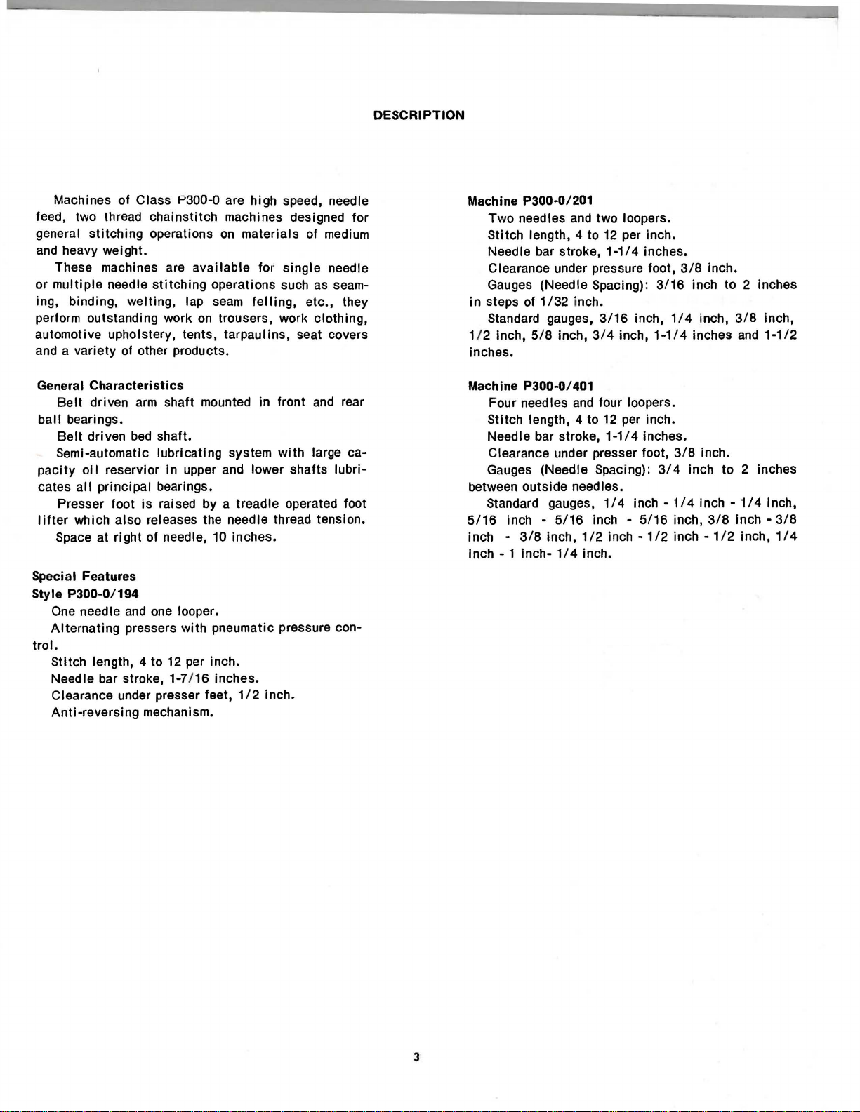
Machines
feed, two thread
general
and heavy
These machines are
or
multiple
ing, binding,
perform outstanding work
automotive upholstery, tents,
and a
variety
General
Belt
ball
bearings.
Belt
Semi-automatic
pacity
cates
Presser
lifter
which
Space
Special Features
Style
P300-0/194
One needle
Alternating
trol.
Stitch
Needle
Clearance under presser feet,
Anti-reversing
of
Class
chainstitch
stitching
weight.
Characteristics
driven
driven
oi I reservior
all
principal
at
length, 4
bar stroke, 1-7/ 16
operations
needle
stitching
welting,
of other products .
arm
bed
shaft.
lubricating
bearings.
foot
is
also
releases the needle thread tension.
right
of
and
one looper.
pressers
to
mechanism.
P300-o are
available
lap seam
on
shaft
mounted in front and rear
in
upper and lower
raised by a treadle operated foot
needle, 10
with
12 per inch.
high
speed, needle
machines designed for
on
materials
for
operations such as seam-
felling,
trousers,
tarpaulins,
system
inches.
pneumatic pressure con-
inches.
1/2
single
work
seat covers
with
shafts
inch.
of
medium
needle
etc.,
they
clothing,
large ca-
lubri-
Machine P300-0/201
Two
needles and two loopers.
Stitch
length, 4 to 12 per inch.
Needle bar stroke,
Clearance under pressure foot,
Gauges (Needle Spacing):
in
steps of
Standard gauges,
1/2 inch,
inches.
Machine P300-o/401
Four needles
Stitch
Needle bar stroke,
Clearance under presser foot,
Gauges (Needle
between
Standard gauges,
5/16
inch inch-1 inch-
1/32
5/8
inch,
length, 4 to 12 per inch.
outside
inch -
3/8
5/16
inch,
1/4
1-1/4
inch.
3/16
3/4
and
four loopers.
1-1
Spacing):
needles.
1/4
inch -
1/2
inch
inch.
inch,
I 4 inches.
inches.
3/16
inch,
1-1/4
3/4
inch
5/16
-1/2
3/8
1/4
3/8
inch
-1/4
inch,
inch
inch.
inch
to
2 inches
inch,
3/8
inches and
inch.
to
2 inches
Inch
-1/4
3/8
inch-
-1/2
inch,
inch,
1-1/2
inch,
3/8
1/4
3
Page 4
HANGERS
OIL
PAN
Fig. 3
Fig. 2
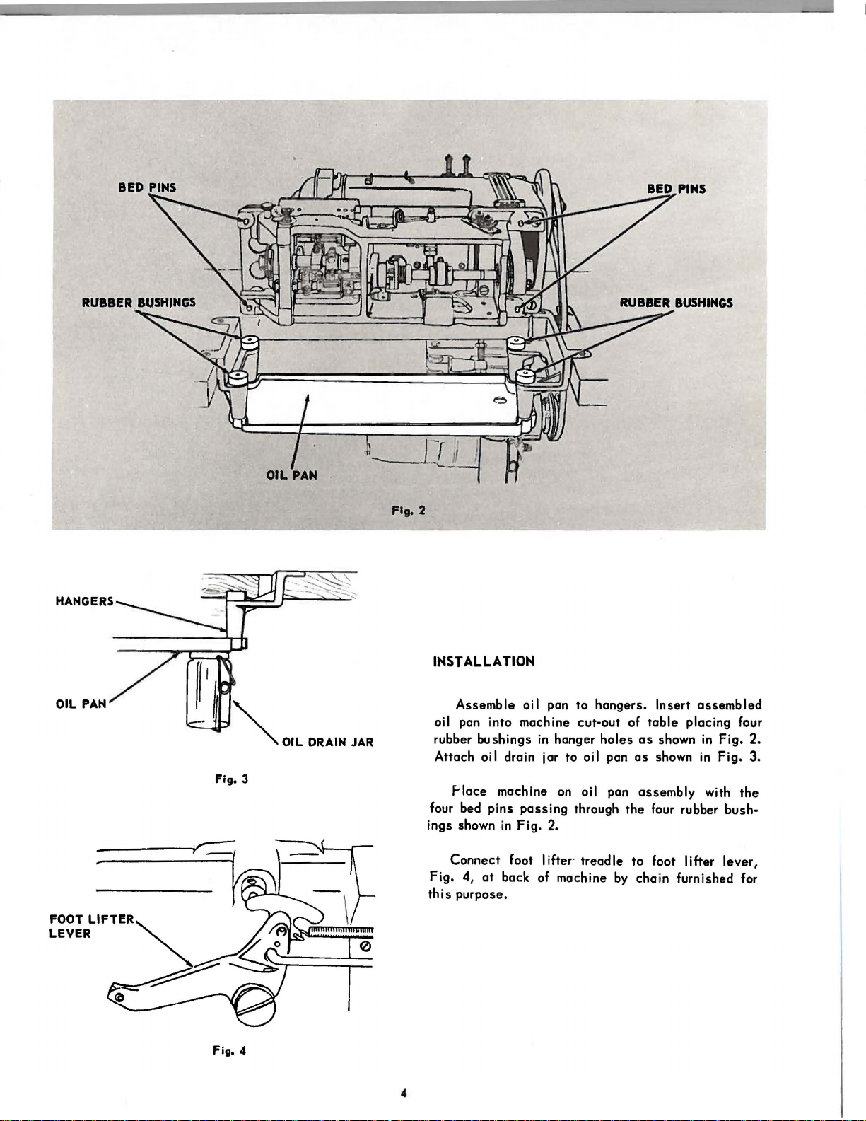
INSTALLATION
oil pan into
rubber
Attach
four bed
ings shown in
Assemble
bushings
F-lace machine on oil pan
oil pan
machine
in
oi I drain jar
pins
passing
Fig.
2.
to
cut-out
hanger
to
oi I pan
through
hangers.
holes
Insert
of
table
as
shown
as
shown in
assembly
the
four rubber
assembled
placing
in
Fig.
Fig.
with
bush-
four
2.
3.
the
FOOT LIFTER
LEVER
Fig.
Connect
Fig.
4,
this
purpose.
4
4
foot I ifter·
at
back of machine
treadle
to
by
foot I i fter
cha
in
lever,
furnished
for
Page 5
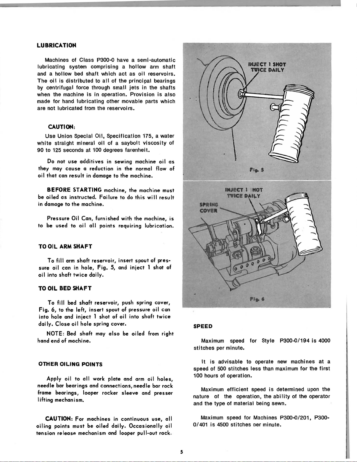
LUBRICATION
Machines of Class P300-o have a semi-automatic
lubricating system comprising a
and
a hollow
The
oil
by
centrifugal force through small
when the machine
made
for hand lubricating other movable parts which
are not lubricated from the reservoirs.
bed
shaft which
is distributed to
is
in
all
operation. Provision
hollow
act
as
of the principal bearings
jets
arm
oil
reservoirs.
in the shafts
CAUTION:
Use
white
90
to
Do
the-y
oil
that
Union Special
straight mineral
125
seconds at 100 degrees farenheit.
not
use
may
cause a reduction
can
result
Oil,
oil
additives
in damage
Specification 175, a water
of a saybolt
in
sewing
in
the
to
the
viscosity
machine oil
normal flow of
machine.
is
shaft
also
of
as
, ... s
BEFORE
be
oiled
as
in damage
to
Pressure
to
be
used
TO OIL
sure
oi
To
oil
I into
ARM
fi
II
can
shaft
TO OIL BED
To fill bed
Fig.
6,
to
the
into
hole
and
daily.
Close
NOTE: Bed
hand end
of
STARTING machine,
instructed.
the
machine.
Oil
Can,
to
oil
Failure
furnished with
all
points
SHAFT
arm
shaft
reservoir,
in
hole,
Fig.
twice
daily.
SHAFT
shaft
reservoir,
left,
insert
spout
inject 1 shot
oil
hole
spring cover.
shaft
may
also
machine.
the
machine
to
do
this
the
machine,
requiring
insert
spout
5, and
inject 1 shot
push spring cover,
of
pressure
of
oil into
be
shaft
oiled
must
wi
II
result
is
lubrication.
of
pres-
of
oil
can
twice
from
right
SPEED
Maximum
stitches per minute.
speed
for Style P300-0/194
is
4000
It
OTHER OILING POINTS
Apply oil
needle
frame
bar
bearings,
to
all
bearings
looper
work
and
lifting mechanism.
CAUTION: For
oiling
tension
points
release
machines
must
be
mechanism and looper
plate
connections,
rocker
in
oiled
daily.
and arm oil
needle
sleeve
and
continuous
Occasionally
pull-out
holes,
bar rock
presser
use,
all
oil
rack
.
5
is
speed of
100 hours
Maximum
nature of the operation, the
and the type of material being sewn.
Maximum
is
0/401
advisable to operate
500
stitches less than
of
operation.
efficient
speed
4500
stitches oer minute.
speed
for Machines P300-Q/201, P300-
new
machines at a
maximum
is
determined upon the
ability
for
the
of
the operator
first
Page 6

NEEDLES
Machines P300-Q/201, P300-0/401 use Needles,
Catalog
P3260 (62 x 57).
MOVE
TO
HIGHEST
POINT
LOOSEN
SCREW
For heavier weight material, needle Catalog
4112 (62x59)
needle bar must
13.
P300-0/194 use Needles, Catalog P4112
for medium heavy work or Catalog
for medium
The
by
the
through
Orders for
quired,
To
Set
The
light
size
size
the
eye
size
number and
Needle
may
work.
of
the
of
the
of
needles
also
be
used. In
be
adjusted as instructed
needle
thread
the
need I
should
catalog
to
be
used
which must
e.
specify
number.
this
P3260 (62 x 57)
is
determined
pass
quantity
P-
case, the
on
page
(62
x 59)
freely
re-
MOVE
TO
HIGHEST
SCARF OF NEEDLE
TOWARD
POINT
LEFT
Fig.
Turn machine pulley over toward
until
the
needle
bar
is
at
its
highest
the
point,
operator
as
shown
in Fig. 7.
Loosen
chines
machines,
Insert
it will go making
needle
LOOSEN
SCREWS
or
needle
as
needle
faces
needle
shown
toward
set
screw
clamping
in
Fig.
into
needle
certain
the
on
screws
on multiple
7.
bar or clamp
that
the
left,
as
single
scarf
shown
needle
needle
as
far
of
in
Fig.
ma-
as
each
7.
THREAD
left
twist
or
right
twist
Either
used
in
the
needles
7
Rough or uneven
through
with
the
needle
successful
and loopers.
thread,
eye
with
operation of
or
difficulty
the
thread
thread
machine.
which
wi
II
may
be
passes
interfer
6
Page 7

THREADitolG
Upper
Threading
THE
MACHINE
Turn machine pulley over toward operator until
needle
points
correct
needle
bar
is
at
its
highest
Pass
thread
indicated
threading
from unwi nder through
in
Fig.
of
needle.
Draw approximately two
eye
with which
to
start
point.
8. See
inches
sewing.
insert,
of
thread
thread
Fig.
ing
8,
for
through
Single and
threaded as shown
thread passes through thread tension
Machines of Class
Pressers are equipped
front
of
the arm. The needle thread must pass through
the lubricator.
multiple
in
Fig.
needle machines are
8. Make
P300-Q
with
having
a thread
certain
device.
lubricator
all
that each
Alternating
on
Fig.
8
Lower
Open front
turn machine
bar
is
LOOP!R
RACK
THROW-OUT
ROD
Move
looper throw-out
throw-out
This
will
ingand
loopers
Threading
LOOP
! R
AR
LOCKING
THROW-OUT
PLUNG
! R
ROD
Pass
GE
points
of thread through looper
sewing.
7
Threading
pulley
at
its
highest
loopers
rack
place
prevent
are
returned
The
Loopers
thread
as
indicated.
table
section,
remove bed
over toward operator unti I
point.
out of sewing
gear
locking plunger rod and looper
rod,
Fig.
8, out
loopers
in
accidental
to
sewing
position
as
far
pos
ition for·
operation of
position.
from unwinder through
Draw approximately
eye
with which
slide
by
as
possible.
easier
machine
threading
two
to
and
needle
pulling
thread·
until
inches
start
Page 8

TENSION
PRESSURE
MORE
TENSION
LESS
TENSION
Fig. 9
Fig.
10
LOOPER
THREADS
Tension
while
still
material.
Needle
screw,
To
Thread
regulate
indicated
IMPORTANT:
only when
Looper
screws,
To
Thread
regulate
as
Alternating
on
thread
sufficient
Tension
needle
in
Fig.
Regulate
pre~ser
foot
Tension
looper
indicated
in
Pressers:
should
to
set
thread
is
down.
thread
Fig.
be
the
9,
as
needle
tension,
10,
light
stitch
tension,
may be
thread
as
may
as
possible
correctly
turn thumb
required.
tension
turn thumb
be
required.
in
Pressure
sible
while
still
Presser
screw,
screw
To
Foot
regulate
Fig.
11,
to
increase
pressure. When
tighten
lock
screw.
on
material
sufficient
Pressure
presser
at
correct
should
foot
rear
of
pressute;
feeding
THUMB
be
to
insure
pressure,
machine.
loosen
pressure
SCREW
as
light
correct
loosen
Tighten
to
is
LOCK
SCREW
as
pos-
feeding.
lock
thumb
decrease
attained,
To
loosen
see
tighten
To
decrease
loosen
When
screw.
increase
lock
Fig.
lock
lock
correct
Then
screw,
12.
screw.
pressure,
screw,
tighten
pressure,
When
correct
Then
then
pressure
the
then
loosen
upper
loosen
tighten
pressure
tighten
tighten
is
attained,
lock
lower lock nut
upper lock
is
attained,
the
lower
lock
upper lock nut•
lower lock
tighten
nut.
and
nut,
nut.
and
nut.
lock
Fig.
11
8
Fig.
12
Page 9
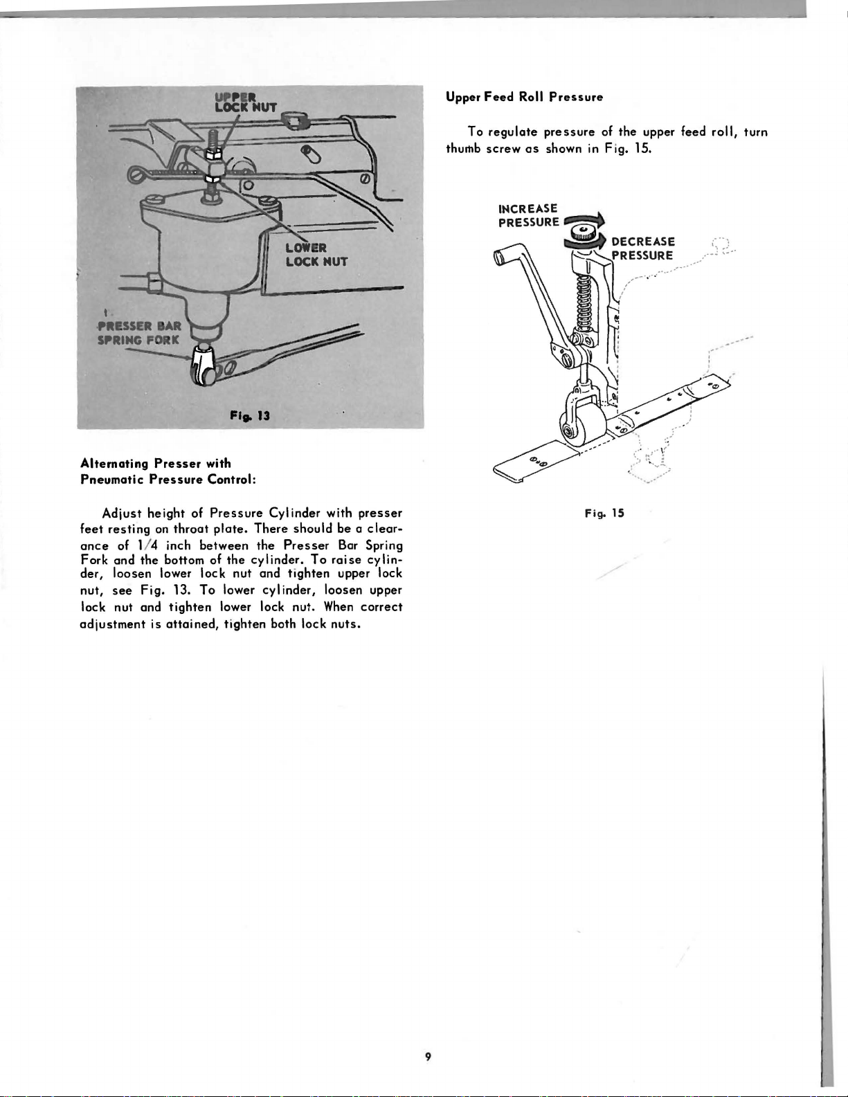
Upper
To
thumb
Feed
Roll
Pressure
regulate
screw
INCREASE~
PRESSURE~
pressure
as
shown in
of
the
upper feed
Fig.
15.
b
~
..
DECREASE
~~RESSURE
u
/.---····
'
.....
··
roll,
turn
;~·)
•....
-·····-~
.-
,.··
_
...
-·
-
·
Alternating
Pneumatic
Adjust
feet
resting
ance
Fork
der,
nut,
lock nut and
adjustment
Pressure
height
of 1/ 4 inch
and
the
loosen
see
Fig.
is
Presser
on
throat
bottom
lower
13.
tighten
attained,
with
Control:
of
Pressure
plate.
between
of
the
lock
nut
To
lower
lower lock nut.
tighten
Cylinder
There
should
the
Presser
cylinder.
and
tighten
cylinder,
both
To
lock
with
presser
be a
clear-
Bar Spring
raise
cylin-
upper lock
loosen
When
correct
nuts.
upper
Fig. 15
··
..
~._
.
....
-··"
9
Page 10
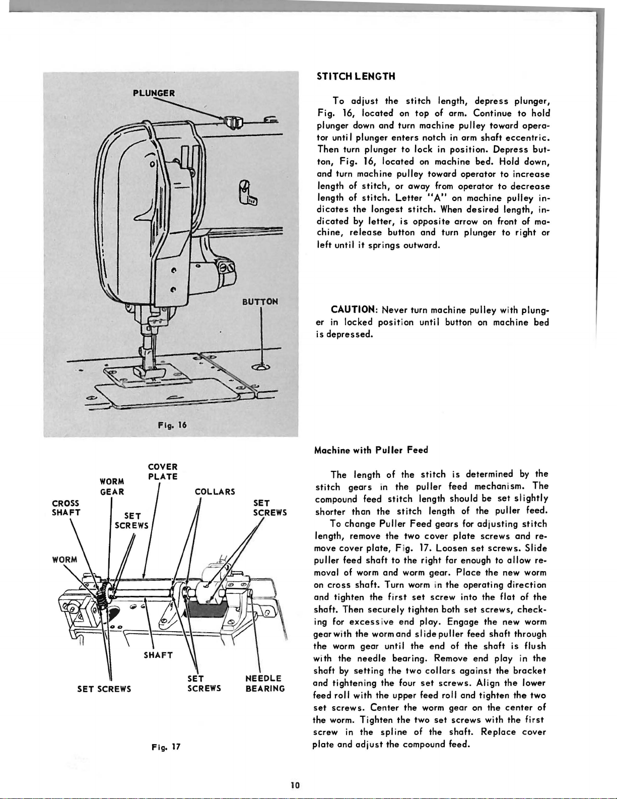
PLUNGER
STITCH LENGTH
To
adjust
Fig.
16,
plunger down
tor unti I
Then
turn
ton,
Fig.
and turn machine
length of
length of
dicates
dicated
chine,
left
the
by
release
unti I
located
and
plunger
plunger
16,
stitch,
stitch.
longest
letter,
it
springs
the
located
button
stitch
on
turn machine
enters
to
pulley toward
or away from
Letter
is
outward.
length,
top
of arm.
notch in arm
lock in
on machine
"A"
stitch.
opposite
and turn plunger
depress
Continue
pulley
position.
operator
on machine
When
arrow on front of ma-
toward
shaft
bed.
operator
desired
eccentric.
Depress
Hold down,
to
increase
to
decrease
pulley
length,
to
plunger,
to
hold
opera-
but-
in·
in-
right
or
SET
WORM
GEAR
SCREWS
Fig.
COVER
PLATE
Fig.
17
16
SET
SCREWS
BUTTON
NEEDLE
BEARING
CAUTION:
er
in
locked
is
depressed.
Machine with
The
length
stitch
compound feed
shorter
length, remove
move
puller
moval of worm
on
and
shaft.
ing for
gearwith
the
with
shaft
and
feed
set
the worm.
screw
plate
gears
than
To
change
cover
feed
cross
shaft.
tighten
Then
excessive
the
worm
gear
the
needle
by
setting
tightening
roll
with
screws.
Tighten
in
the
and
adjust
plate,
shaft
the
securely
Center
Never
turn
posit
ion
Puller
wormand
the
Feed
of
the
in
the
stitch
the
stitch
Puller
spline
Feed
the
two
F ig. 17.
to
the
and
worm
Turn worm in
first
set
tighten
end
unti I
the
bearing.
the
two
the
four
upper
the
the
the
compound
machine
until
stitch
puller
length
length of
gears
cover
Loosen
right
gear.
screw
ploy.
slide
puller
end
Remove
collars
set
screws.
feed roll
worm
two
set
of
the
pulley
button on
is
determined
feed
should
for
plate
set
far
enough
Place
the
operating
into
both
set
Engage
feed
of
the
end
against
and
gear
on
screws
shaft.
feed.
with
machine
by
mechanism.
be
set
slightly
the
puller
adjusting
screws
the
the
screws,
the
shaft
Align
tighten
with
Replace
screws.
to
allow
new worm
direction
flat
new worm
shaft
is
play
the
the
the
center
the
and
check-
through
in
bracket
the
plung·
bed
the
The
feed.
stitch
re-
Slide
re-
of
the
flush
the
lower
two
of
first
cover
10
Page 11
PRESSER
When
bar
lifter
the
point
the
presser
BAR
the
and
of
presser
the
the
foot.
HEIGHT
foot
needle
needle
is
raised
is
at
should
by
the
presser
its
highest
not protrude below
position,
To
adjust,
ator
until
set
screw,
height,
tighten
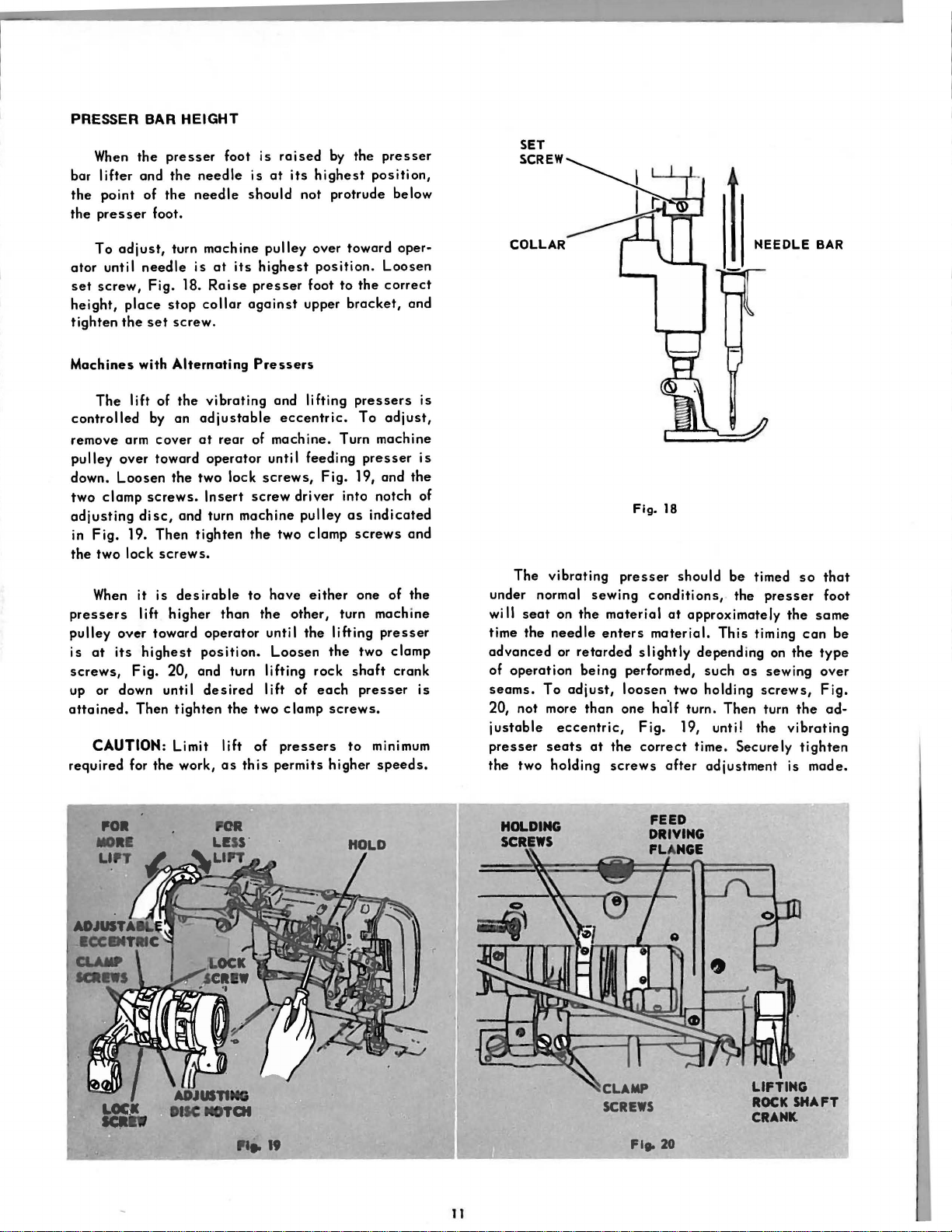
Machines
controlled
remove arm
pulley
down.
two
adjusting
in
the
pressers
pulley
is
screws,
up or down unti I
attained.
required
place
the
The
over
Loosen
clamp
Fig.
two
When
over
at
its
CAUTION: Limit
needle
Fig.
set
with
lift
by an
screws.
disc,
19.
lock
it is
lift
highest
Fig.
Then
for
of
cover
toward
Then
screws.
toward
the
turn
18.
stop
screw.
Alternating
the
the
and turn
desirable
higher
20, and turn
tighten
work,
machine
is
at
its
Raise
collar
vibrating
adjustable
at
rear
operator
two
lock
Insert
machine
tighten
than
operator
position.
desired
the
lift
as
this
pulley
highest
presser
against
Pressers
and
eccentric.
of
machine.
until
screws,
screw
the
two
to
have
the
until
Loosen
lifting
I ift of
two
clamp
of
pressers
permits
over
position.
foot
upper
lifting
feeding
driver
pulley
clamp
either
other,
the
rock
each
toward
to
the
bracket,
pressers
To
Turn
machine
presser
Fig.
19, and
into notch of
as
indicated
screws
one of
turn
machine
lifting
the
two
shaft
presser
screws.
to
minimum
higher
speeds.
oper-
Loosen
correct
and
adjust,
the
and
the
presser
clamp
crank
is
is
is
COLLAR NEEDLE
Fig.
18
The
vibrating
under normal
wi
II
seat
on
time
the
needle
advanced
of
seams.
20, not more
justable
presser
the
or
operation
To
eccentric,
seats
two
holding
adjust,
presser
sewing
the
material
enters
retarded
being
than
at
the
screws
should
conditions,
at
material.
slightly
performed,
loosen
one
two
ha'lf turn.
Fig.
correct
after
be
timed
. the
approximately
This
timing
depending
such
as
holding
Then
19, unti! the
time. Securely
adjustment
so
presser
the
can
on
the
sewing
screws,
turn
the
vibrating
tighten
is mode.
BAR
that
foot
some
be
type
over
Fig.
ad-
,o.
IIIORI
HOLDING
SCREWS
un
tt:t.
DISC
IIOTOI
.....
19
II
SCREWS
Fl•
20
LIFTING
ROCK
SHAFT
CRANK.
Page 12
CLAMP
SCREW
FEED
TIMING
LIFT
SCREW
CRANK
TO
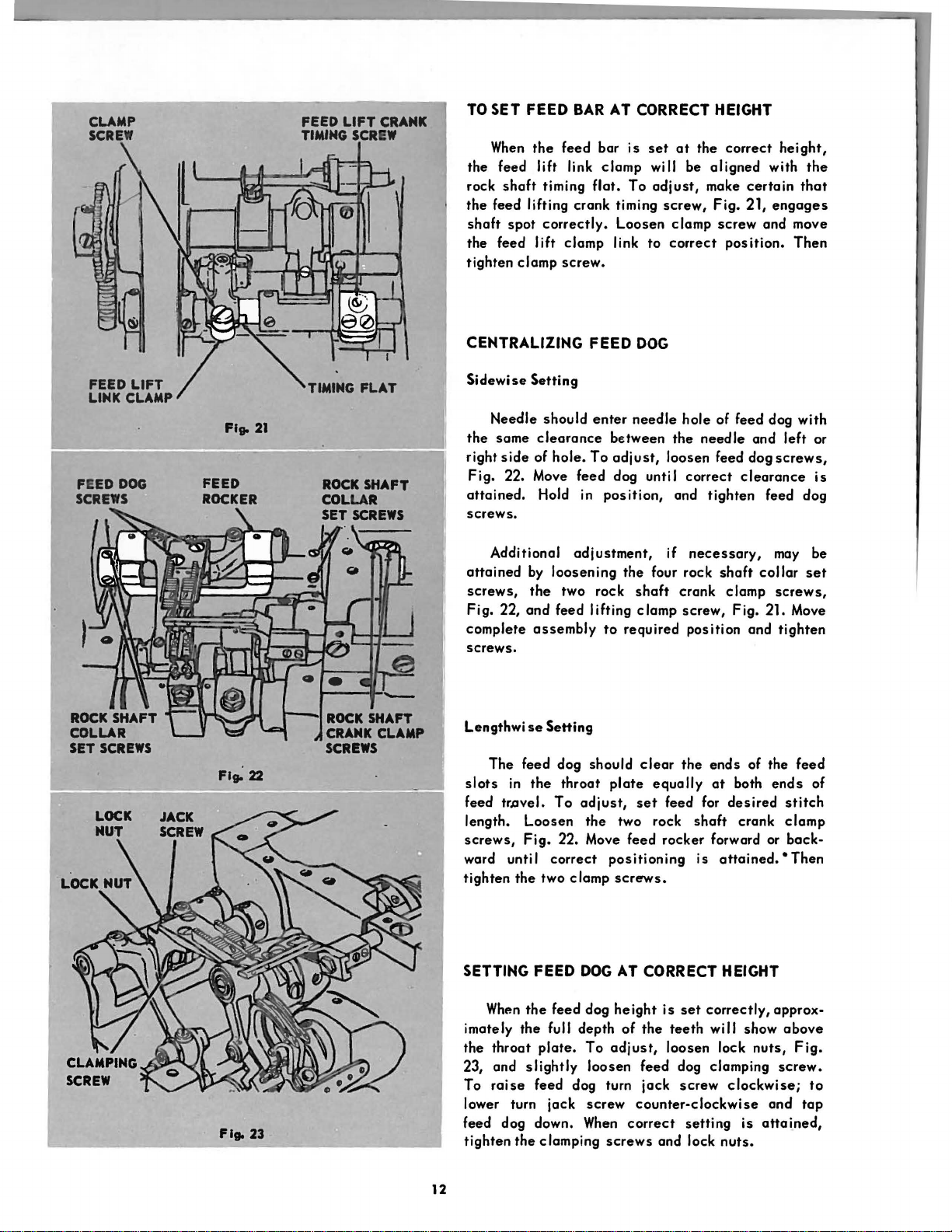
SET FEED BAR
When
the
feed
the feed lift link
rock
shaft
timing flat.
the
feed lifting crank timing
shaft
spot
correctly.
the feed
tighten
lift
clamp
clamp
screw.
AT
CORRECT HEIGHT
bar
is
set
at
clamp
To
will
be
adjust,
screw,
Loosen
link
to
clamp
correct
the
aligned
make
Fig.
screw
correct
with
certain
21,
engages
and
position.
height,
the
that
move
Then
FEED
LINK
FEED
DOG
SCREWS
LIFT
CLAMP
FEE
D
ROCKER
TIMING
FLAT
CENTRALIZING FEED
Sidewise
the
right
Fig.
attained.
Setting
Needle
same
side
should
clearance
of
hole.
enter
between
To
adjust,
22. Move feed dog unti I
Hold in
position,
screws.
Additional
attained
screws,
Fig. 22,
complete
and
adjustment,
by
loosening
the
two rock
feed
assembly
lifting
to
screws.
Lengthwise
The
slots
feed
length.
screws,
ward unti I
tighten
Setting
feed dog should
in
the
throat
tr.ovel.
To
Loosen
Fig.
22. Move
adjust,
the
correct
the
two
clamp
plate
positioning
screws.
DOG
needle
hole
the
loosen feed dog
correct
and
if
necessary,
the four rock
shaft
crank
clamp
screw,
required
clear
position
the
equally
set
feed for
two rock
feed
rocker
of feed dog with
needle
and
clearance
tighten
feed dog
may
shaft
collar
clamp
Fig. 21. Move
and
ends
of the
at
both
ends
desired
shaft
crank
forward or
is
attained.
left
or
screws,
is
be
set
screws,
tighten
feed
of
stitch
clamp
back-
• Then
SETTING FEED
When
the
feed dog
Flto 23
imately
the
23, and
To
lower turn
feed dog down.
tighten
12
the
throat
plate.
slightly
raise
feed dog turn
the clamping
full depth
jack
DOG
To
loosen
screw
When
screws
AT
CORRECT HEIGHT
height
adjust,
of
the
is
set
teeth
loosen
feed dog clamping
jack
screw
counter-clockwise
correct
setting
and lock
correctly,
will show
lock
nuts,
clockwise;
is
nuts.
approx-
above
Fig.
screw.
to
and
tap
attained,
Page 13
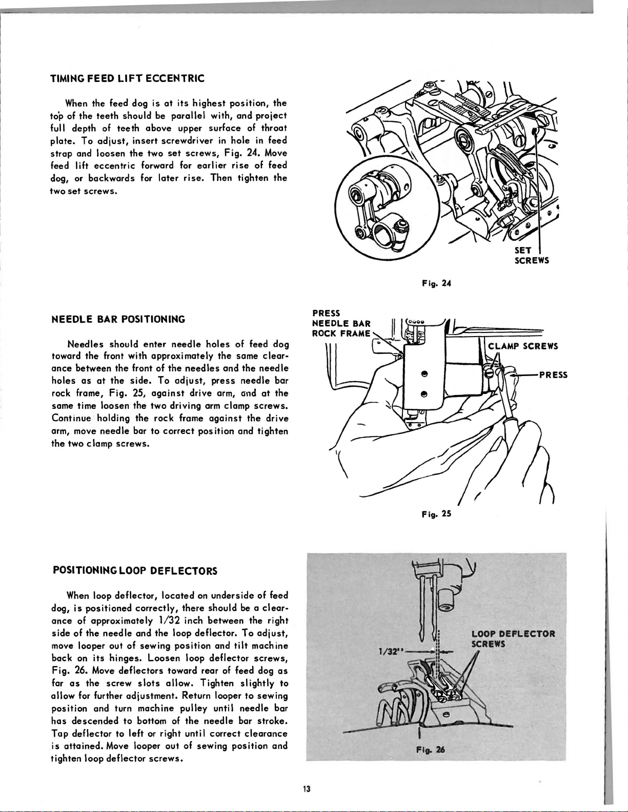
TIMING
to'p
full depth of
plate.
strap
feed
dog, or
two
FEED LIFT ECCENTRIC
When
the feed dog
of
the
teeth
To
adjust,
and
loosen
I ift
eccentric
backwards
set
screws.
should be
teeth
above
insert
the
two
forward for
for
is
at
its
parallel
upper
screwdriver
set
screws,
later
rise.
highest
with,
surface
earlier
Then
position,
and
in
hole
Fig.
rise
tighten
the
project
of
throat
in
feed
24. Move
of
feed
the
Fig. 24
NEEDLE
toward
ance
holes
rock frame,
same time
Continue
arm, move
the
BAR
Needles
the
front with
between
as
at
loosen
holding
needle
two clamp
should
the
the
Fig.
POSITIONING
When
loop
deflector,
dog,
is
positioned
ance
of
approximately
side
of
the
needle
move looper out
back
on
its
hinges.
Fig.
26. Move
far
as
the
screw
allow
for further
position
has
Tap
is
tighten
and turn machine
descended
deflector
attained.
Move looper
loop
deflector
POSITIONING
enter
approximately
front of
side.
25,
the
the
bar
screws.
LOOP
correctly,
and
of
deflectors
adjustment.
to
bottom of
to
left
the
To
against
two
driving arm clamp
rock
to
correct
DEFLECTORS
located
1/32
the
sewing
Loosen
toward
slots
allow.
or
right
out
screws.
needle
loop
holes
needles
adjust,
frame
position
pulley
press
drive
against
posit
on
underside
there
should
inch
between
deflector.
and
loop
deflector
rear
Tighten
Return looper
until
the
needle
until
correct
of
sewing
of
feed
the
same
and
the
needle
arm,
and
screws.
the
ion and
be
o
the
To
tilt
machine
screws,
of feed dog
slightly
to
needle
bar
clearance
position
dog
clear-
needle
bar
at
the
drive
tighten
of
feed
clear-
right
adjust,
as
to
sewing
bar
stroke.
and
Fig.
Fig.
25
26
13
Page 14

LOOPER
HOLDER
1/16
..
Sidewise
When
of
the
the
forward
chine
pulley
side
the
screw,
correct
the
looper
SETTING
Setting
the
looper
looper
stroke
center
Fig.
27, and
clearance
holder
LOOPER CARRIER
CLAMP
just
until
of
NUT
is
clears
of
the
the
the
tap
is
attained.
screw.
correctly
looper
needle.
Fig. 27
the
looper.
holder
THE
positioned,
scarf
of
To
adjust,
point
is
Loosen
to
left
Then
securely
LOOPER
the
the
needle
turn ma-
directly
looper
or
right
tighten
AT
point
on
oppo-
holder
until
CORRECT
clearance
Fig.
To
looper
attained.
two
chines,
just
just,
needle,
looper
screws.
Lengthwise
Height
DISTANCE
Move
looper
between
28,
which
adjust,
set
CAUTION:
clears
to
Hold in
screws.
make
with
loosen
slightly
of
Needle
loosen
left
the
looper
Setting
FROM
to
heel
should
the
or
right
position
On
single
certain
scarf
point
the
two
to
left
and
Bar
Fig.
28
NEEDLE
extreme
of
be
two
until
that
of i
ts
directly
set
or
right.
Setting
forward
looper
approximately
looper
and
and
the
respective
screws,
position.
and
loop
set
correct
securely
multiple
point
of
needle.
opposite
Fig.
Then
tighten
Check
deflector,
1116
screws.
clearance
tighten
needle
each
To
center
28,
and
the
inch
Turn
is
the
ma-
looper
ad-
of
turn
set
.
When
correctly
be
Fig.
29
NEEDLE
CLAMP
~
BAR
SCREWS)!~
I
j~
'
..
\
~
Fig. 30
directly
the
center
needle
pulley
To
ing
nut,
until
needle.
To
needle
as
far
ing
screws,
to
correct
clamping
when
is
adjust
Fig.
looper
Then
adjust
is
as
possible.
screws.
opposite
of
the
opposite
the
tighten
inserted
Fig.
position.
14
the
looper
looper,
29.
point
needle
set,
the
the
center
clearance
timing
the
Move
carrier
is
directly
clamping
bar,
up
into
Loosen
30,
and
Then
point
timing
loosen
first
the
the
raise
securely
of
the
looper
of
the
needle,
above
the
mark L T on
arrow on
looper
carrier
forward or
opposite
nut.
make
needle
two
needle
or lower
tighten
eye
machine
the
backward
center
certain
bar
or
bar
needle
should
and
of
arm.
c Iamp-
clamp
clamp-
the
at
the
of
that
bar
two
Page 15

TIMING LOOPER DRIVING CRANK
When
the
looper driving crank
the
point
of the looper will
the
needle
and backward
To
forward
screw,
at
adjust
stroke,
Fig.
the
same
strokes
when point of looper
loosen
31.
Loosen
(left) approximately
crank timing
correct
set
screw.
When
stroke,
screw
screw
adjustment
point
of
reverse
the
(right) and
looper
of
1/8
(right). Continue
is
adjustment
tightening
pass
distance
the
on both
looper.
looper driving crank
looper crank timing screw
turn, and tighten looper
made. Then
passes
higher on backward
by loosening timing
timing screw (left).
is
properly timed,
above
passes
to
the
the
forward
higher on
adjust
securely
eye
of
set
unti I
tighten
TIMING
(RIGHT)
DRIVING
SET
SCREW
SCREW
CRANK
SETTING THE
When
pass
as
touching.
operator until
pass
the
point,
the
needle
close
To
adjust,
the
needles
NEEDLE
guards
as
points
on
GUARDS
are
properly
possible
to
turn machine pulley over toward
of
the
their
forward
looper timing mark L T on
pulley should be approximately
arrow on machine arm.
screws,
needles
screws.
and turning
the
Fig
32. Turn
as
possible
Check
by
springing
the
maching pulley
looper points do not
Loosen
needle
guards
without touching. Tighten
the
stroke
set,
they should
the
needles
without
loopers are about
strokes.
1/8
inch above the
needle
as
needles
to
make
the
needles.
At
the
machine
guard
close
to
the
certain
to
to
this
set
t4le
set
left
that
Fig.
31
NEEDLE
SET
SCRE
GUARD
W
15
Page 16

Fig.
SPREADER
SET
--
~
33
SCREWS
HOLDER
'
-l
SPREADER
4
-
Flg.U
POSITIONING
Sidewise
spreader
SPREADER
DRIVING
ROCK SHAFT
and
When
looper on
••••
The
point
opposite
looper.
The
clearance
looper should
thickness
SPREADER
Height
Setting
its
of
the
top of
between
be
of ordinary
forward stroke
spreader
thread
approximately
should
groove
spreader
paper.
is
be
at
left
point and
the double
passing
exactly
side
of
To
adjust,
set
screws,
correct
setscrews.
Lengthwise
stroke
clearance
mately
Fig.
correct
CHANGING MOVEMENT
adjusted
normal
generally
hinges,
screws,
centric
crease
When
driving
strap
ceeding
position.
Setting
When
the
is
even
between
1/16
inch. To
34,
and
position.
The
sidewise
for
sewing
conditions,
used.
loosen
Fig.
flange
movement, or to right to
correctly
eccentric
and
tighten
information regarding
loosen
Fig.
33. Move
Hold
point
of
with the point of the
the
adjust,
move
spreader
Then
movement
under abnormal
maximum
To
adjust,
the
two ·
35,
and
screws.
positioned,
screws
flange
the
two
spreader
spreader
in
position
the
needle
two points should be
loosen
forward or backward
tighten
the
Move
spr'eader
OF
SPREADER
of
the
spreader
tilt
machine back on
spreader
two
spreader
eccentric
decrease
tighten the two
first, hold flange
screws.
positioning
and
and
on
its
spreader,
spreader
screw.
spreader
conditions.
movement
driving
driving
to
Then refer
of
holder
holder
tighten
left
movement.
spreader.
the
downward
the
approxi·
screw,
may be
Under
is
its
eccentric
ec·
to
in·
spreader
against
to
pre·
to
to
SPREADER DRIVING
ECCENTRIC
SCREWS
FLANGE
Fig. 35
16
CAUTION:
allow
driving rock
centric
eccentric
sufficient
ball
When
strap.
ball
increasing
clearance
shaft,
Fig.
They should not touch when
stud
is
sidewise
35, and
in
its
between
left
highest
movement,
spreader
side
of
position.
ec-
Page 17

ADJUSTING NEEDLE THREAD TAKE-UP
The
needle
be
adjusted
thread drawn
To
increase
screw,
screw
reverse
raising
Fig.
and lower the guide. To
the
the
thread
to
increase
at
the top of
the
amount,
36, and
adjustment
guide.
take-up
raise
and thread guide may
or
decrease
the
needle
loosen
by lowering the
thread take-up
take-up
decrease
or
the
loosen
the
amount of
bar
stroke.
guide
amount,
take-up
set
or
5/8"
GUIDE
THREAD GUIDE
SCREW
For
average
set
be
screw.
lower
ADJUSTING NEEDLE THREAD TENSION RELEASER
should
the
tension
set
out for
lease.
the
rect
the
sidewise
with upper end
The
end
When
release
presser
when
screw,
earlier
Hold
tension
time after making the
tension
sewing
thread
1/2
inch below
correctly
tension
foot
presser
Fig . 37,
release
in
posit
releaser
releaser
to
correct
take-up
adjusted,
is
raised
foot
and
ion and
not
plate
position.
conditions,
5/8
inch above
should be
the
bottom of
the
on
the
needle
and allow full
is
down. To
move
tension
of
tension
tighten
release
above
adjustments,
screw
Then tighten screw.
the
guide should
set
tension
thread when
adjust,
releaser
or
in
for later re-
set
screw. Should
tension·
and
the
with
its
holder.
releaser
adjusted
at
the
move
guide
the
loosen
cap
cor•
loosen
plate
\--.;..;......;---TAKE-UP
Fig.
36
TENSION RELEASER
PLATE
NEEDLE THREAD
ADJUSTINGLOOPER THREAD TAKE-UP
The
looper
justed
for hand I ing more or
thickness
change
stitch.
To
looper
thread
take-up
right for
making
the
To
stitch,
lower
more
Hold in
of material and length of
the
change
thread
take-up
certain
center
change
loosen
the
thread.
position
thread
ratio
the amount of thread handled,
rod
less
of
yoke or right
take-up
of looper
guide
rod screw. Move thread guide and
to
the
left for more thread or
thread.
that
the
guide yoke.
ratio
of
thread guide
For
less
and
and guide
less
thread,
thread
screw,
take-up
tighten
Fig.
Tighten the two
rod
looper
thread,
thread
screw,
end
of thread guide for
raise
guide screw.
according
stitch,
in
the
38, and looper
passes
Fig.
end of
may
finished
in
finished
38, and
be
ad-
to
and
to
loosen
to
the
screws
through
guide.
17
Fig. 37
LOOPER THREAD
,
TAKE-UP
....
ROD
Page 18

Page 19

Cat.
No.
P51
173
STYLES
P300-0/194, P300
PARTS
LIST
-0/
201,
P300-0/401
Page 20

Page 21

UNION
SPECIAL
NOTE:
~
200 125(833)
..-
Z68169~
268168-
268603
268344
r
l--
201.C16(830)
268030
•~ns~
200029(805)
200100(803)
200053(819)
fi
268618
268318
200172(805)_..
(4
~
167416
268071
268368
<1
268.
1•
267
Jl
I
i
Page 22

Page 23

added
8029
to
all
part numbers required.
200078(805)
~
268010
268176--
-
--
• ....,._
I'
226206
200064(806)
71
268367
{
8368 268099(2)
200362(803)
268061
398812
268051
Page 24

Page 25

268315
~
-
.
~
\4L350477(830)
\241763
.____
267623
350548(803)
r-
q
350534(803)
268049
~
£1
200054(803)
268064
3::::1(803)
268044
l
268123
.
l.t,
200054(803)
200562(805)
Page 26

Page 27

NOTE: When
ordering
replacement
NUMERICAL
parts
from
this
LIST
catalog,
OF
a
"P"
prefix
must
PARTS FOR BASIC MACHINE
be
added
to
all
part
numbers
required.
PART
NO.
1454
(830)
2102
8582
10148
32572
32825 Spreader Driving Rock
32835
32835
32848
50169(809)
50326(803)
51570 (830)
54279
59537
59538
59539
67425
131741
140306 (869)
140321 (830)
140321 (830)
140321 (830)
141432 (819)
141478 (869)
141494 (869)
141495 (830)
156695
167188
167416
167416
DESCRIPTION
Presser
Screw
Needle
Disc
Arm
Looper
Spring
Needle
Releasing
Shaft Screw Stud
Packing
Feed
complete, Nos,
268065, 268066, 268067
and 268315
Needle
Driving
complete,
268065, 268066, 268067
and 268315
Arm
(Front)
Looper Thread Guide (top
of
Needle
Stud
Needle
Thumb Nut
Needle
Thread
Needle Thread
Spring Bushing (Front)
Needle
Spring Bushing
Needle
Stud 50326 (803) with
51570 (830)
Looper
Clamping Stud Washer
Needle
Spring
Feed Lifting Cronk
Screw
Feed
Collar
Feed
Collar
Spreader Driving Rock
Shaft
Looper
Stud
Needle
(Bock)
Needle
(Front)
Feed
Spreader Driving
Pin
Face
Plate
Feed
Collar
140321 (830)
Feed
Collar
140321 (830) (2)
Foot
Shank
Thread
(2)
Position
Thread
Thread
Driving
Shaft Boll
Arm)
Thread
Thread
Thread
Guide (double)
Thread
Thread
Carrier
Thread
Driving Rock Shaft
Set Screw (4)
Lifting Rock Shaft
Set Screw (4)
Collar Set Screw (4)
Thread
Guard Set Screw
Dog Shonk Screw
Plate
Driving Rock Shaft
with two
Lifting Rock Shaft
with two
Tension
Pin
Tension
Tension
Disc
(Wick)
Bar Rock Frame
Eccentric
Bracket
Guard Set Screw
Oi
Eccentric
268064,
Nos,
268064,
Bearing
Screw (2)
Tension
Tension
Tension
Tension
Tension
(Back)
Tension
Crank
Tension
Tension
Eccentric
Lock Spring
(2)
(2)
I
Pinch
Pinch
PART
NO.
167416
200004 (805)
200029(805)
200035 (805)
200047 (804)
200047(805)
200053 (819)
200054 (803)
200058 (803)
200059
(8
05)
200061
(833)
200061 (833)
200061
(8
33)
200064 (806)
200070 (803)
200078 (805)
200078 (806)
200082 (804)
200085(803)
200089 (803)
200095 (819)
200098 (806)
200100 (803)
200100 (805)
200125
(8
33)
200138 (804)
200172 (805)
200173 (804)
200226 (805)
200303(819)
200327 (803)
200328 (8:Jl)
200337 (803)
200344 (830)
200346
(80
3)
DESCRIPTION
Spreader Driving Rock
Shaft
Collar
140321 (830) (2)
Arm
Screw
Arm
Head Screw
Spreader Bar Bearing
Screw
Arm
Shaft Ball Bearing
(Back)
Needle
Bracket
Bed
Plate
Looper Thread
Clamp Screw (4)
Needle
Driving
Screw (2)
Looper
Screw
Feed
Crank
Feed
Crank
Needle
Stud
Looper
Rod
Set Screw
Presser
Bracket
Arm
Side Cover Screw
Feed
Socket Screw (2)
Needle
Screw
Looper Carrier Shaft
Bushing (Left)
Plate
Looper Cprrier Crank
Hinge
Needle
Link Cop Washer Screw
Looper Throw•out Safety
Latch
Screw
Feed
Throat
Needle Set Screw
Bed
Plate
Screw
Loop Deflector Screw (2)
Needle
Holder Screw (2)
Presser
Support Screw
Looper Driving Crank Oil
Hole Cover Screw
Machine
Machine
Screw
Needle
Regulating Stud
Set
Screw
Looper Driving Cronk
Position
Needle
Screw
with two
(4)
(3)
(2)
Housing Screw (3)
Thread
Thread
Driving Rock. Shaft
Pinch
Lifting Rock Shaft
Pinch
Pinch
Thread
Regulating Stud
Thread
(3)
Screw (2)
Pin
Bar
Spring Brocket
(2)
Dog
Plate
(4)
Bar
Bar Rock Frome
Bar Crank Set
Tension
Screw
(2)
Screw (8)
Tube
Bar Rock
Arm
Pinch
Guide
Screw
Screw (2)
Bar
Connecting
Screw (2)
T ake•up
Bar Guide
Pinch
Screw
Guide
Position
Pinch
Connecting
Screw (2)
Screw
Slide Spring
Oiling
Bar Spring
Pulley
Pulley
Screw (2)
Frame
(2)
Screw
(3)
Felt
Set Screw
Position
Sleeve
(3)
PART HO.
200354 (803)
200354 (803)
200354 (803)
200362
(803)
200 362
(8
30)
200362(830)
200362 (830)
200364 (803)
200364 (803)
200364(803)
200364 (830)
200373 (803)
200373 (803) Spreader Driving Cronk
200378 (803)
200380 (803)
200380 (830) Spreader Holder Set
200382 (833)
200382 (833)
200394 (803)
200403 (830)
200403 (830)
200444 (803)
200541 (805)
200562 (805)
200571 (850)
200572(806)
200573 (804)
200578 (850)
200582(803)
DESCRIPTION
Feed
Driving Rock
Position
Looper Carrier Shaft
Bushing
Screw (2)
Needle
Position
Looper Driving Crank
Set
Feed
Set Screw
Looper Carrier Shaft
Bushing Set Screw (2)
Looper Throw•out Gear
Set Screw (2)
Looper Throw•out
Locking
Screw
Needle
Regulating Stud Cap
Set Screw
Spreader Driving
Eccentric
Spreader Driving
Eccentric
Set
Feed
Pin
Position
Needle
Position
Screw
Presser
Collar
Screw (2)
Feed
Adjusting
Collar
Needle
Driving Eccentric:
ing
Set Screw
Feed
Set Screw (2)
Feed
Spreader Driving Crank
Set
Looper Throw•out
Locking
Screw
Needle
Releasing
Looper
Bracket
Face
Screw
Presser
Bracket Adjusting Screw
Looper Driving Crank Oil
Stop Screw
Looper Thread Guide (top
of
Needle
Thread
Screw
Position
Bar Crank
Screw
Screw
Driving Rock
Plunger
Set Screw
Bar Rock
Set Screw
Counterbalance
Screw (2)
Lifting Link Hinge
Set Screw
Screw
Bar Crank
Screw
Bar
Set Screw
Driving Eccentric:
Disc
Set Screw (2)
Bar
Disc
Spring
(2)
Lifting
Bar Set Screw (2)
Screw
Plunger
Thread
Plate
Thread
Screw
Plate
Lock Spring
(2)
Bar Guide
Arm)
Bracket Screw (2)
Bar
Rock
Guide Screw (2)
Frame
Frame
Gear
Stop
Frame
(2)
Check
Stop
Spring
Rock Frome
Adjust•
Collar
Eccentric:
Gear
Stop
Tension
Screw
Tension
(2)
Frame
Page 28

NOTE:
200934 (806)
201020
201052
201160 (805)
201185 (804)
201185
20l188(803)
201188 (803)
201254(830)
201254 (830)
201363 (803)
201416 (830)
20.t418 (803)
201477 (803)
201522 (805)
201522 (005)
201522 (805)
201524 (805)
201525 (805)
201537
201553(804)
201572 (819)
201620 (804)
201736 (805)
202005
202120
202120
202253
202330
203349
PART
When
NO.
(805)
(833)
(804)
(819)
ordering
DESCRIPTION
Foot
lifter
Hinge
Screw
Spreader
Connection
Needle
Thread
Releaser
Foot
Lifter
Screw
Eye
Feed
Driving
Cap
Screw
Needle
Driving
Bar
Connection
Screw
Feed
Bar
Collar
Set
Needle
Needle
Stud)
Arm
Belt
Bed
Pulley
Foot
Thread
Bar
Set
Shaft
Pulley
Shaft
Set
lifter
Screw
Face
Plate
Set
Screw
Feed
lifting
Crank
Position
Looper
Throw•out
locking
Plunger
Bushing
Feed
Driving
Hinge
Stud
Feed
lifting
Hinge
Stud
Needle
Driving
Stud
Nut
Looper
Bar
Connection
Carrier
Clamping
Feed
Dog
Lock
Nut
Feed
Dog Shank
Adjusting
looper
Throw•aut
Rod Thumb
looper
Thread
Thumb
Nut
Looper
Throw•out
locking
Plunger
Nut
Spreader
Shaft
Arm
Presser
Driving
Screw Stud
Screw
Bar
Pin
Foot
lifter
Stop
Pin
Arm
Shaft
Belt
Pulley
Flange
(2)
Needle
Stud
Needle
Rei
Bar
Oi I Packing
Thread
easing
Washer
replacement
lifting
Driving
Cap
Screw
Tension
Cap
Set
Lever
Connection
Rock
Frame
.
Hinge
Pin
Screw
Guide
Connecting
Screw
Connection
Set
Screw
Connection
Screw
(2)
Lever
Hinge
(2)
Rock
Screw
Screw
Connection
Nut
Connection
Nut
Rock
Frame
Crank
Stud
Nut
Shank
Screw
Screw
Lock
Nut
Tension
Thumb
Rock
Nut
Washer (4)
lever
lifting
Connection
Spring
Connecting
(Wick)
Tension
PI
ate
Screw
parts
NUMERICAL
Link
(2)
Screw
Spring
Cap
(on
(2)
Belt
Hinge
Stud
Shaft
Gear
Hinge
Nut
Rack
Gear
Stop
Link
from
LIST
PART
203759
204235
204348
204365
204925
204925
206335
208636
208636
214529
214529
226080
226206
228448
238089
240245
241763
241763
244048
248423
250265
259470
264709
267623
267623
267933
268003
268004
268006
268009
268010
268017
268022
268024
this
NO.
catalog,
OF
a
PARTS
"P"
FOR BASIC
DESCRIPTION
Presser
with
Arm
Foot
Needle
Releaser
Looper
Hole
Spreader
Presser
Feed
Bar
200380(803)
Head
lifter
Thread
Spring
Driving
Cover
Screw
Foot
Dog Shank
Washer
Looper
Holder
Washer
Needle
Bar
Regulating
Presser
Cushion
Presser
Needle
Bar
Spring
Foot
Thread
Releasing
Machine
Needle
locating
Thread
Releasing
Feed
Regulating
Retaining
Feed
Friction
Screw
Needle
Driving
Friction
Screw
Looper
Disc
Foot
Cotter
looper
locking
Feed
with
Needle
Spring
Driving
Plate
Packing
Bar
Eccentric
Plate
Packing
Thread
(2)
lifter
Pin
Throw•out
Plunger
Bar
Hinge
201188 (803)
Bar Rock
Regulating
200364 (803)
Feed
Driving
Friction
Needle
Driving
Plate
Bar
Eccentric
Plate
Feed
lifting
Arm
Shaft
and
Shaft
Housing
Shaft
with two
Shaft
(Front)
Side
Plate
Plate
Shaft
with
Ball
Connection
Oil Stop
Cover
268044, 268264 two
268214
Arm
(Back)
Arm
Pulley
201254 (830)
Arm
Spring
Arm
Bed
268022 and four
200138(804)
Bed
Arm
(Back)
prefix
Stop Co
Position
Lever
II
Pin
Spring
Tension
Crank
Screw
Washer
Washer
Hinge
Pin
Screw
Screw
Rock
Frame
Stud
Spring
Spring
Plate
Spring
Ten~ion
Pin
Stud
Tension
Plate
Pin
Stud
Eccentric
Screw
(Brass)
Rock
Frame
Screw
(Brass)
Tension
lever
Rod
(2)
Gear
Spring
Pin
Collar
Frame
Stud
Cap
Eccentric
Rack
Frame
Friction
Rock
Shaft
268009,
each
350534 (803)
Bearing
each
and
202253
Ball
Slide
with
Slide
Spring
Bearing
Ball
must
be
added
MACHINE
PART
(4)
(2)
(2
(2)
)
268024
268028
268029
268030
268032
268033
268035
268044
268044
268045
268046
268047
268048
268049
268051
268052
268053
268054
268055
268060
268060
268061
268061
268062
268062
268062
268063
268063
268063
or
Oi I 268029
Set
Set
with
Belt
two
to
NO.
all
part
Hinge
Needle
Driving
Stud
Needle
Needle
Driving
Spreader
Connection
numbers
required.
DESCRIPTION
Bed
Shaft
Bed
Pulley
201254 (830)
Bed
Bearing
Needle
Needle
Face
and
Face
Face
Feed
Arm
Spring
Bed
Ball
Shaft
Connection
with two
Shaft
Needle
(2)
Bar
Rock
Bearing
Plate
with 268033
two 201416 (830)
Plate
lock
Plate
lock
Bar
Hinge
Shaft
Oi
I Stop
(Rear)
Shaft
Oi I Stop
Spring
Spreader
with
200364 (803)
Spreader
Counterbal
200 364
Feed
1 566
(8
lifting
Driving
95
and
Driving
once
30)
Eccentric
with 268077 and
200394 (803)
Machine
Pulley
(Aluminum Alloy
for
"V"
Belt
(Outside
Diam.
of
Belt
2.9
In,)
and
200328 (830)
Machine
with
268024
looper
looper
Groove
with 200327
Pulley
Thread
Thread T ake•up
Rod
Spreader
Shaft
Bed
268214, 268265
350534 (803)
Needle
link
Feed
Need
Driving
Feed
268060 wi
Need
Driving
268060 wi
Feed
Hinge
Feed
Driving
with
Shaft
with
Bar
with
twa
Drivi
ng
I e
Bar
Connection
Driving
th
I e
Bar
Connection
th
Driving
Stud
lifting
Stud
200064 (806)
Connecting
270266
Connection
Rock
Connection
268063
Rock
268063
Connection
with
Connection
with
Bar Rock
Connection
with
268258
Feed
Driving
Connect
Bearing
Bar
Rock
Connection
Bearing
Driving
Need
Bearing
Frame
(2)
Spring
Stud
Pin
Ba
Ball
Eccentric
two
Eccentric
with
two
two
Casting)
(803)
268048
Guide
Rock
268044,
and
Frame
Frame
268258
268
258
Frame
Hinge
Frame
Needle
I e
Bearing
Belt
II
ion
Page 29

NOTE:
When
ordering
replacement
NUMERICAL
parts
from
this
catalog, a "P"
LIST
OF
PARTS
FOR
prefix
BASIC
must
be
MACHINE
added
to
all
part
numbers
required.
PART NO.
268064
268064
268065
268065
268066
268066
268067
268067
268069
268070
268071
268071
268071 Spreader Driving Rock with 32848
268073
268074 Feed Lifting
268075
268077
268078
268079
268081
268082
268083
268085
268086
268087
268094
268096
268098
268099
268099
268102 Looper Driving Crank Oil
268111
DESCRIPTION
Feed
Driving
Needle
Driving
Feed Driving
Adjusting
Needle Bor Rock Frame 268124
Driving
Adjusting
Feed
Driving
Adjusting
Needle
Driving
Adjusting
Feed
Driving
Adjusting
Collar
200382 (833)
Needle
Driving
Adjusting
Collar
200382 (833)
Feed
Driving Rock Frame
with 200354 (803) and
200362 (830) 202330 and two
Feed
Driving Rock Shaft 200061 (833)
Feed
Driving Rock Shaft
Needle
Feed
Lifting
Needle
Shaft Needle
Feed
Driving Rock Shaft
Crank with two
200061 (833)
Feed
Lifting Crank with 268150
140306 (869) and 200373
Feed
Lifting
Lubri
eating
Feed
Lifting Link
Feed
Lifting Link Hinge
Pin with 268258
Feed
Regulating Stud 268162 Spreader
Feed Regulating Stud
Socket
Foot
Lifter
Foot
Lifter
238089
Foot
Lifter
with two 248423
Foot
Lifter
Looper Carrier Shaft with
Bushings
Looper Carrier Shaft
Bushing (Left)
Plate
Looper Driving
Looper
Bearing (2)
Looper Driving
Connection
Bearing
Hole Cover
Looper
(top
of
Eccentric
Bar Rock Frame
Eccent'i
Eccentric
Bar Rock
Eccentric
with two
Bar Rock Frame
Eccentric
with two
Bearing (2)
Bearing
Carrier
Thread
Arm)
c 268121
Eccentric
Disc
Disc
Eccentric
Disc
Spring
Frame
Disc
Spring
Eccentric
Disc
Spring
Disc
Spring
Rock Shaft
(2)
Bearing
Connection
Eccentric
Pad
(Wood)
(2)
Bell Crank
Lever
with
Lever
Rod
Lifting
Needle
Link 268171
Position
Connection
Needle
Guide
Bracket
(2)
PART NO. DESCRIPTION PART
Looper
268121
Needle
268123
268126
268127
268129
268131
268132
268133
268139
268141
268142
268143
268144
268148
268149
268161
268167
268168 Needle Thread
268169
268172
268173
268174
268176
268181
268184
268185
268186
Presser
.Bracket with 200070 (803)
and 200572 (806)
Presser
Spreader Bar
Spreader Bar Bearing
Spreader Holder with
200380 (830)
Spreader Driving
201020 (805)
Thread
Bracket
Bracket
Looper
Looper Thread Tube
Clamp
Looper
with
Looper
Locking
Looper
Rod
Looper
Safety Latch
Looper
Safety Latch Spring
Looper Throw-out
Safety
Bracket
Needle
Link Cap Washer
Needle
Stud with
Needle
200346 (803), 200354
and
Needle
Needle
Needle
Regulating Stud
Needle
Regulating Stud Sleeve
Needle
Regulating Stud complete,
Nos.
268148 and 268149
Needle Bar Rock Frame
Driving
200058 (803)
Needle
Bracket 268264
Releaser
Needle
Releaser
201052 (833)
Needle
Releasing
(adjustable)
Presser
Presser
Connection with two
Spacing
Thread
Spacing Collar
Thread
(2)
Throw•out Gear
two
Throw-out Gear
Throw•out Rack 268214
Throw•out
Throw•out
Latch
Bar Connecting
Bar Connecting
Bar Crank with
200378 (803)
Bar Crank 268142
Bar Oiling
Bar Rock Frame
Bar Rock Frame
Bar Rock Frame
214529, 264709, 268261
Arm
Thread
Thread
Thread
Bar
Bar Bushing
Bar Guide
Bar Spring
Tension
Collar
Tension
Tube
200362(830)
Plunger
Spring
201188 (803),
Felt
with two
Point
Tension
Tension
Tension
Cap with
Tension
Plate
(2)
(803)
two
NO.
268187
(2)
268190
268198
268208
268214
268216
268219
268220
268233
268258
268258
268258
268258
(2)
268258
268263
268265
268270
268275
268277
268278
268291
268307
268308
268310 Needle Guard
DESCRIPTION
Spreader
with 200373(803) and
200403 (830)
Spreader Driving
Feed
Crank with
and two 200061 (833)
Looper Carrier Crank
Hinge
Arm
5/32
Bed
Looper Driving
Connection 268098 with
268099
Needle
Thread Guide
Spreader Driving
Eccentric
(2)
Spreader Driving
Connection 268186 with
268063 and 351876
Feed
Hinge Stud
(Wick)
Feed
Hinge Stud Oil
(Wick)
Feed
Pin
Looper Carrier
Hinge
(Wick)
Needle
Driving Connection
Hinge Stud
(Wick)
Bed Shaft Connection
Belt
268024
Needle
complete, Nos. 32572,
59537, 59538, 59539,
131741 and two 2102
Arm
(Wood)
Bed Shaft
(Wood)
Arm
Belt
Presser
1454 (830)
Looper
200362 (830), 200573 (804)
and two
Needle
Holder (2)
Feed
and
Looper Carri
200089(803)
Looper Carri
Clamping Stud
Driving Crank
Lifting Rock
Pin
Shaft
ln.
Di
Shah
Bar Rock
Driving
Lifting Connection
Lifting Link
Oil
Packing
Pin
Bar Rock Frame
Pulley
Thread
Shaft
Shaft Connection
(reinforced
Foot Shank with
Driving Crank with
200344 (830)
Bar
Bar with 200373 (803)
two
200403 (830)
Pin
Shaft
201418 (803)
with 268258
Oi
I Stop Ball
am.
(2)
Oil Stop Ball
Frame
Thrust
Washer
Connection
Oil
Packing
Packing
Hinge
(Wick) (2)
Crank
Oil
Packing
Oil
Packing
268028 with
Tension
Oi
I Control
Oi
I Control Rod
neoprene)
Oiling
Felt
er
Crank with
er
Crank
Rod
Page 30

NOTE:
When
ordering replacement parts from
NUMERICAL
this
LIST
catalog, a
OF
"P"
prefix
must
PARTS FOR BASIC MACHINE
be
added to
all
part numbers required.
PART
NO.
268312
268513
268602
268603
268611
268612
268313 Looper Throw-out Gear
268314 Looper
268315 Feed Driving
268315
268316
268318
268330
268331
268332
268333
268344
268367
268368
268373
268380
268382
268402
268462
268495
268505
268506
268512
DESCRIPTION
Needle Thread Guide (on
Arm
Head)
Needle Thread Guide (on
Side
of
Arm)
(2)
Looper Holder with two
350478 (833)
Needle
Bar with
200125
(833)
Presser
Presser
Spring inch) with 268318 and two
Locking
Rod 268129 with
201553
267623, two
350467 (830), 350477 (830)
and
Needle Bar Rock Frame
Driving
267623 two
350467
and 350548
Feed
201537 (819) and
350552 (830)
Loop
Face
Looper Thread
Bracket
Looper Thread
complete, Nos, 10148,
141432(819
and two 244049
Looper Thread
Thread Guide
Needle Bar Rock Frame
Looper Carrier
Looper Carrier 268367
with two 268099
Looper Thread Guide
(on Bed
gauges
2
Looper with 141478 (869) Screw (2)
and 141494 (869)
Looper and
complete,
268380
Bed
Bed
Looper Throw•out Safety
Latch
Looper Thread Guide
(top of
Looper Thread Guide
(top of Arm)
268111 with 268505 and *398803
two
Needle Thread Guide (on 268208, 268216, 268307,
Needle
Stud)
Foot
Plate
Foot
Plate
Heel
Plunger Handle 268638
Throw-out Rack 270026
(804)
Flange
each
241763,
350548 (803)
Flange
with
each
(830), 350477 (830)
Dog
Shank with
Deflector
Plate
at
from
Inches
Nos,
Plate
Plate
Retaining Ring
Arm)
50169 (809) with 67425, 201524 (805),
Bar Connecting
241763,
(803)
Hinge Stud
Tension
Tension
),
201572(819)
Tension
Looper) for all 350478 (333 )
3/16
to
Needle
(left)
(Right) Driving
Guard
268310 and
Bracket
with
(2)
PART
NO.
268613
268614
268618
270266
350013
(803)
350149 (803)
350267 (805)
(803)
350381
350446 (803)
350467 (830)
350467 (830)
350467 (830)
(805)
350468
350477 (830)
350477 (830)
350478 (833) Looper Set Screw
350534 (803)
350534 (803) Bed Shaft Oil Stop Ball
350548 (803)
360548 (803)
(830)
350552
351876
DESCRIPTION
Presser
Hinged)
Needle Hole, Nos.
206335, 226080,
268275,268611 and
268612
Throat
Feed
Hole, for
and
200172 (805)
Spreader with 268162
Feed
Spring
Needle
Link
Foot
Hinge Screw
Spreader Screw
Looper Holder Screw
Presser
Adjusting Screw
Spreader Driving Rock
Shaft Screw Stud with
32825
Feed
Screw (2)
Needle
Driving
Screw (2)
Presser
Adjusting Screw Set
Screw
Looper Thread Guide (on
Bed
Feed
Friction
Screw (2)
Needle
Driving
Friction
Screw
Looper Adjusting Screw
Arm
Screw
Feed
Friction
Needle
Friction
Feed Dog Shank Adjusting
Screw
Spreader Driving Rock
Shaft Screw Stud
Roller
Looper Carrier 268368
and
Foot (Spring 398804
complete,
Plate
Dog,
Needle
22
(teeth
Regulating Stud
Bar Connecting
Needle Beari':Jg
Lifter Bell Crank
Bar Spring
Driving F1ange
Bar Rock Frame
Flange
Bar Spring
at
Looper)
Driving
Plate
Bar Rock Frame
Eccentric
Plate
(2)
Shaft
Oi
Driving
Plate
Bar Rock Frome
Eccentric
Plate
268308
46
Needle
cut
for
Set
Eccentric
Screw Set
Screw Set
I Stop
Eccentric
Screw
Screw
46
Sizes
15
to
268614
Ball
Ball
(2)
Set
(2)
(2)
PART
NO.
Bed
with 240245, 268081,
268082, 270026 and two
200078 (806)
Needle
Driving
201185 (804), 201522 (805),
268061
Foot
268083 with 200394 (806)
and
Feed
Crank 268073 with
201185 (804), 201522 (805),
268061 and 268062
Needle Bar Crank
268143 and 200095 (819),
268003, 268055, 268139
and 268141
Looper Driving Crank
268
201522 (805),
268047, 268062, 268074,
268102 and 268198
Needle
268344 with 268603 and
two each 200173 (804),
268144 and
20
the
398807
398809
398812
*398816
*398817
* 398818
ACCESSORIES
PART
NO.
265307
350598
228731
200019 (805)
232365
202784
268340
167448 Machine
228444 Machine Cushion
41400 Machine
228733 Machine
228734
NDL. Type
P3260
Bed Hinge Connection (2)
Bed Hinge Connection
Screw (4)
Drip
Drip
Foot
41·1
Foot
Hook (2)
Looper Threading Wire
Jar
(neoprene)
Machine
Needles
DESCRIPTION
Plate
(Right) 268462
Bar Rock Frame
Arm
268161 with
and 268062
Lifter Bell Crank
268087
Driving Rock Shaft
277 with 200303
DESCRIPTION
Pan
Pan
Lifter
/2
Lifter
204925,
Bar Rock Frame
268
278
Screw (4 )
Treadle
inches
long
Treadle
Base
Oi
I Drain
(4)
Rest
Pin
(Wood)
Rest
(left)
Rest
(Right)
(62x57)
Size
(819
),
Chain,
Chain
22(6)
*NOT ILLUSTRATED
AS
A COMPLETE ASSEMBLY
Page 31

NOTE:
When
ordering replacement parts from
CHANGE BASIC
SUPPLEMENTARY PARTS
(Same
as Complete
LIST
AS
List
for BASIC MACHINE
INDICATED
this
LIST
catalog, a
"P"
prefix
must
be
added
to
all
FOR P300-o/201 and P300-o/401 MACHINES
with
the
Parts
following
To
Be
EXCEPTIONS)
Added
part numbers cequired.
BASIC
NUMBER HUMBER
For
P300-0/201
268618
268602
HEW
Machine
267802 (016)
268 1 03
(0
16)
DESCRIPTION
Feed
Dog,
46
neea1e
for
needle
(teeth
with two
cut
268318
sizes
15 to
20
the
and
and
inch)
200172 (805) for 267851
Looper
Holder
with four
hole,
four
22
CODE HUMBER
For
P300-0/201
For
P300-0/401
350478 (833)
268603 268136
398818 398806
268613
267872 (016)
268611 267871
268638
268374
228745 228746
268614
For
268618
267851
P300-0/401
269006(501)
(016)
(016)
Machine
Needle
Needle
268344
two
268144
Presser
hinged)
needle
226080,
and 268612
Presser
Spreader
Thread
Throat
Feed
for
(teeth
with four
Bar
Bar
with
each
and
Foot
complete,
hole,
267871, 268275
Foot
with two 268162
Unwinder
Plate
Dog, 46
needle
cut
Rock
Frame
268136
and
200173 (804),
268278
(spring
46
Nos.
206335,
Plate
complete
needle
sizes
20
and
15
to
the
inch)
268318
and
hole,
22
eight
50014 (830)
269234
2 271115
200583 (819)
3
4 350089 (803)
5 271116
3505 15
6
7
213910
200172 (805) for 269379
268602
269065 (501)
268603 268136
398818 398806
268219 269138
268167
268514
268168 268515
268613
269237
(503)
(504)
Looper
350478
Needle
Needle
268344 with 268136
two
268144
Needle
Thread
Needle
Bracket
Needle
Releaser
Presser
compensating)
46
(833)
each
needle
Holder
with
Bar
Bar
Rock
200173 (804),
and
268278
Bar
Rock
Guide
Thread
Thread
Foot
holes,
Tension
Tension
(hinged
complete,
eight
Frame
and
Frome
Nos.
269234, 269235 (505),
269236 (803), 271115,
271116, 271117, 271119,
350515, two
200583 (819)
Omit
206335
268612
1454 (806) Omit
268611
268611
268275
Part
Omit
Part
Part
269235
26
9236 ( 505)
271117
(505)
268275 271119
226080
268638
228745
268614
26231
269342
228748
269379
(501)
(501)
Presser
Presser
Spring
Presser
Screw
Presser
Presser
Presser
Presser
Presser
Spring
Spreader
Thread
Throat
each
26231,
and
213910
Foot
Hinge
Foot
Plate
Foot
Shank
Foot
Plate
Foot
Plate
Foot
Shank (left)
Foot
Shank (right)
Foot
Plate
(2)
with four 268162
Unwinder
Plate
complete
Pin
Heel
Pinch
(left)
(right)
Machine
268151
(0
16)
50014 (830)
Machines
269191 (501)
(803)
DESCRIPTION
Needle
Holder with two
50014 (830)
Needle
Needle
Set
Holder
50014 (830)
Needle
Presser
Set
Foot
350089(803)
Presser
Plate
Presser
Plate
Presser
Screw
Presser
Lever
Presser
Lever
Presser
Pin
Foot
Foot
Screw
Foot
Foot
Foot
Hinge
Foot
(2)
Screw
(2)
with four
Screw (4)
Bracket
Bracket
Bracket
(2)
Bracket
Connection
Connection
Screw
Plate
with
Cover
Cover
Pinch
Hinge
Page 32

NOTE:
When
ordering replacement parts from
this
catalog, a
"P"
prefix
must
be
added to
all
part numbers required.
Form P21441
(565)
Supplement
Form P21331
PARTS ADDED
200346(830)
204648
268416
208127
268418
270026
270078(803)
268403
268090
268205
to
22988
22982
22983
22984
22985
22986
22987
22990
22989
22970
23108
23109
SUPPLEMENTARY
UNION
STYLE
PARTS
SPECIAL
P300-0/194
MACHINE P300-o/194
Same
as parts shown
except for
Anti
-reversing
22986 and 22987
Anti-reversing
Anti-reversing
Anti-reversing
Anti-reversing
Anti-reversing Roller
Anti-reversing
Anti-reversing
Anti-reversing
22989, 204648, 208127, 268416, 268418
Anti-reversing Roller
Anti-reversing Roller
Anti-reversing
Anti-reversing
Anti-reversing
Anti-reversing
Anti-reversing
Screw(2)
Anti-reversing
200078(803)
Bed
Plate
Feed
Driving
Feed
Regulating
Looper
Looper
Roller
Roller
Roller
Roller Clutch
Roller
Roller
Roller
Roller
Roller
Roller
Roller
Roller
Roller
Device
(right)
Eccentric
Stud
Carrier
Carrier
268090 with two 268099
on
Form P21331 on next page
following
DESCRIPTION
Clutch
Complete
Clutch
Clutch
Bushing
Bushing
Clutch
Housing
Clutch
Housing
Clutch
Retaining
Clutch
Retaining
Clutch
Releasing
Clutch
Releasing
Clutch
Releasing
Clutch
Re Ieos ing
Clutch
Releasing
Clutch
Releasing
Clutch
Releasing
Clutch
Releasing
Complete,
Adjusting
Nos.
Disc
LIST
FOR
items.
Nos, 22983, 22985,
with two 200346(830)
Set
Screw(2)
22984 with 22982
Washer
Washer
22988,
Latch
and
Latch
Latch
Latch
Latch
Latch
Latch
Latch
Retainer
Complete,
270026
Hinge
Stud
Stud
Stud
Stud
Stud
22990
Pin
Pin
Socket
Spring
Socket
and
Nos.
two
PARTS
268462
268065
268081
268367
268368
REMOVED
Page 33

Form
Supp.
P21489
to
Form
(566)
21323
INSTRUCTIONS
UNION
ANTI-REVERSING MECHANISM
ON
MACHINE
Machine Class P300-0/194
To
release the device, depress button located
pulley
machine
To
engage the device, release button and turn machine
vice
"snaps"
either forward
into
place.
TO
RELEASE
PRESS
HOLD
DOWN,
AND
MACHINE
is
equipped
or
backward.
TURN
PULLEY
with
J
-\
~
FOR
USING
SPECIAL
STYLE
an
P300-0/194
ANTI-REVERSING device.
on
right side of
pulley
TO
bed
toward rear
ENGAGE
RELEASE
AND
TURN
BACKWARDS
I
plate,
hold down and turn
of
BUTTON
PULLEY
machine
until
de-
EQUALIZING
The
should
lesser
chine
ment.
page
10.
needle
also
distance
pulley,
The
stitch
THE
feed
move
as
FEEDING
and
the
same
than
the
required,
length
drop
needle
to
of
MOVEMENT
feed
distance
feed,
cause
both
feeds
ON
should
during
the
STYLE
depress
drop
can
not
feeding.
feed
then
OF
P300.0/194
only
be
the
stitch
movement
be
reset
THE
NEEDLE
timed
to
If
the
drop
length
to
equal
simultaneously,
move
simultaneously,
feed
moves o greater
button
the 11eedle
FEED
and
turn
as
described
AND
feed
but
the
ma-
move-
on
Printed
DROP
or
in
U.
FEED
S. A.
Page 34

Page 35

Form P21331
Rev.
(56S)
NOTE:
When
ordering
replacemen
t parts from
UNION
SPECIAL
267738
r Ll-'-
201416(830)
200353(803)
267663
""''
~
268312
268056
..
"""~
200029(80S)~
_;:_56200064(804)
w-
236957
268462
tt
/t-
2000
..
81ll)
200053(819)
'9
(4
Page 36

Page 37

acement parts
from
this catalog, a
"P"
prefix must
be
added
to
all
part numbers required.
54
10/)__
~
267738
-268505
~~~-50169(809)
268506
267715
267714
267650
200098(:06t
~~
268150
200123(804)-
931758
994778
~
-'200364(803)
U-
- ·
t
j26825
-
~
268061
~
•
...
268063
267638
264709
200337(803)
268149
268148
214529
8
200043(
®
-~
26801
267701
~-------
200928(850)
803)
200047(
~'
~
.....
-e,20003S
21
Page 38

Page 39

1121
I
I
268009
NOTE:
,
~0·
I
I
~
200047(804)
350534(803)
268214
268044
268044
268214
350534(803)
~
/4
-
268125
~
268124
'
200054(1")3)
--268123
'
200047(805)
·
~
'·
0 "
'268051
'
200035(804)
268064
268124
'"~
268125
'
Page 40

Page 41

NOTE:
Ill
lfiZZOI169I
10000fll05l
1000191105}
10001011191
Z00035CI041
10001!51105)
l0004011lO}
10004111011
Z000471104I
Z00047(105I
10005111191
Z000541101I
100051111011
Z0005IIIID11
10006llll11
Z00061IIl11
100061lllll
100064C1061
Z0006411041
100066110fl
100069(1011
10007111051
Z0007IIII06}
100071111061
10007111061
ZOOOIIII031
1000Bll10fl
10001511011
100019(1011
1000,51119}
ZOOO,III106}
1000911106}
2001001101)
100100(1051
1001Zll104l
Z001Zll10fl
10016411191
10016711051
ZOOI7lll04}
10010111191
Z003Z7II011
10D3ZI!I011
100ll71101l H ..
1003oHIUO)
1003"11031
100151IUO}
Z00351I101I
Z00354110l)
Z001HI103I
1001541101) Naed.le
100)6Z(I011
Z0016Z4101}
10Dl6ZI1011
When
PART
NO.
U17IIOll
zozz
ZlDZ
UH
1511
10141
11971
119ll
22741
lZ57Z
5001411011
50169CI091
50lZ&(I01} N
5157011011
5H79
59517
59518
5951,
67U5
67U5
HI
ordering replacement parts from
NUMERICAL
DESCIIIPT1011
Pnaaer
B&r
Preaa\ue
Phanaer
Nut
Llftlaa
Rock
Needle
Tlu'ea4
U.W.na
Rock
Pin
111
Arm
Poeldoa.
Looper
Thread
Loopu
ThJ'OW'-out Jt.ack Rod
Loopu
Throw-out
with
ZOU51I10fl
Preuer
Bar
Waaber
NeedJ.e
Thread
Needle
Sea
Screw
Looper
Tb,..ad
Bracket
Screw
..
dle
'l'br•d.
..
dle
TbrMd.
N
NHdle
Thread
(double)
N
..
dle
Thraad
(front)
Needle
Thread
(back
I
Needle
Thread
50lZ61101I
with
Looper
Carrier
Waeher
Pl'aeeer
Bar
Support
Stud
N
..
dle
Tb.read
Needle
Quard
Arm
Suew
Arm H .. d Screw())
1JJtiDI
Rock
Looper
Thread
Spnadu
Bar
Feed
Doa
SbaDk
Needle
Bar
Arm
Piacb
Screw
Arm
Shalt
Ball
lDJ
Scuw
(S)
Needle
'Thread
Screw
(Z)
Bed
Plate
Suew
Looper
Thread
Foot
LUter
Llftina
Eccentric
Pt.ach
Screw
J'eed
l>rlviftl
Pinch
Screw
F
..
d LlftiA&
Pinch
Screw
LUtloa
Crank
Looper
Thread
Screw
Thread
Lubricator
LlftlD1
Preuer
Pinch
Screw
Needle
Bar
Screw
(Z)
Arm
Side
Co't"er
Feed
R.eplatlnJ
LlftiDa
Preuer
VJbratiAa
Preuer
LUttaa
Preuer
AlljuetJDa
Screw
Needle
Thread
Looper
Carrier
PoeJtton
Plate
Looper
Canler
Pinch
Suew
Needle
Bar
Waeher
Screw
Looper
Tbrow·out
Bracket
Screw(~)
Preuer
Bar
Support
Retalaer
Fud
Doa
Screw
'1'hr011.t
Plate
Feed
DrJvinl
Needle
Bar
CoanecUon
Cap
Bad
Plate
Slide
Lifttn1
Link
Needle
Bar
Looper
dle
Needle
Llftln1
Looper
Feed
Liftln1
Looper
Dririna
Bar
Sleeve
Drlrina
Bar
Preeeer
(upper)
Plate
DrlviDI
Carrier
(Z)
Bar
Drlvina
Lenr
C.rrlar
(Z)
OUln1
Pullay
Pulley
Hla.ae
CZI
Screw
Machine
Machine
Stud
Looper
Ill
Screw
Face
(loarl
Feed
Screw
Screw
Screw
Cylinder
(Z)
Shalt
CraDic
Teaelon
Dbc
Sbaft
Bracket
Pin
(Z)
Tenaloa
Sprina
Rack
Spri.Da
Arm
Tanelota .S.eleaalDI
Ciuide
(top
(Z)
TeAeloD
Stvd
Tesaelon
Thumb
Tu.eioa
Thread
'l'eaeioD
Sprlaa
TeneloD
SpriDI
TeaeioD
Stud
5157011011
CraAk
Clampha1
Pn
..
ure
CyUndn
Nut
Lock
Wuher
TeneloD
SpriDJ
Sea
Screw
C-4)
Shaft
Bracket
GuJ.de
Screw
BeariOI
Screw
Screw
Rock
Frame
(Z')
Bearlna
Taneion
(8)
Tub•
Clamp
Arm
Pi.Dch
Screw
Coftnection
(ZI
Rock
Sh&ft
(Z)
Rock
Shaft
(Z)
Pinch
Scr.,.,
Taka-up
Screw
Ba1"
Ciu1de
Connecdn1
Screw
(l)
Stud
Socket
Foot
Pinch
Foot
Bar
Ciulde
Cuide
Scrftl'
Shaft
Budll.na
Screw
U)
Crank
HlDae
Coua.ecttn1
Unk
Safety
Pnuura
Cylinder
Screw
CZ)
(Z)
Screw
(3)
ConuecUoD
Rock
Frame
Scrow
Sprtna
Scuw
Kin1•
Pin
Set
Felt
Holder
CraDk
OU
Set
Screw
Poaltloa
Rock
Frame
Set
Screw
Craak
Poattlon
Craak
Set
Screw
Bar
Guide
S.ud
Set
l\ock
Frame
Shaft
Buebln1
Crank
PoelUon
Rock
I'
ram•
Hlaae
Stud
Shalt
B\lebina
Pill
(Z)
Po.ttioa
Rod 21972
tuna•
of
Arm)
Bueblaa.
Bl
Screw
(Z)
Dl'lrinJ
(back)
Houe·
Bracket
Screw
£rank
Cruk
Cra~tk
Rod
Set
Black
Stud
Pinch
Screw
Screw
Pinch
Screw
Block
(Z)
(left)
Pin
CaP
L.atch
Cap
Screw
Drlvtna
(4)
Screw
Screw
Hole
Cover
Scrll'*
RealollatlnJ
Screw
Rod
Set
Screw
Poaltion
Poettlon
Scr.w
Set
Scnw
Set
Scr•wCZ)
Set
Scnw
Dbc
Nut
Qulde
...
Stu.d
(Z)
Sprlna
(ZI
hlDJ
(t)
(Z)
this
catalog, a
LIST
OF PARTS
PART
NO.
UOUZ(IOl}
20016ZII01l
10016411031
1001641101}
20016411011
10016418011
200171(
200)71(8011
1001UII031
200l7BII011
1003BDII011
10018011011
ZOOliOII011
Z001BZI1lll F .. d Drlvtna
1001I&IUOI
100386CI011
ZOOli6II011
1001161110)
1003B&I10ll
1001941101}
Z00f01IB011
Z00401IUOI
100417IUOI
1004\8(1011
20044411011
10056ZC8D51
200571(1501
Z0057li8D41
Z00571I150I
10058111011
10065011191
Z00907(119l
Z009ZIIIUOI
Z0091ll1191
OZDIIDSI
101
Z0105ZIIl11
ZOI06lCI051
ZOIIIOI119I
101160(1051
101111111011
Z0UHCI011
101Z5fll011
ZOIZHII011
10U561UOI
101l6lCI011
ZOI409I106)
ZO!f16IUOI
101411(103}
ZOI477II011
Z015ZZI105l
ZOI5ZZII051
ZOI5ZZ(I051
Z015Z4IIOSI
ZDI5Z5(105I
Z015Z6IIOSI
ZOU17I119I
ZOIS51II041
ZOIS7ZI119I
10161011041
1016ZZI119l
10171611051
101H6I1191
101005
10Z2SJ
ZDZUO
101574
Looper
Looper
Spnader
b&Laa.ce
Spreader
IZI
Looper
PlUAIU
N'
..
Stud
101 I Feed
IZI
Foot
Spuader
s ......
Needle
Check
Feed
UJUna
Screw
Spreader
Dl.ec
F
..
Sc
F
..
Screw
LlftiDI
IZI
Looper
Collar
Spr•du
Set
J'aed
F
..
Spreader
Llttlna
Scnw
L.IJUnJ
l..ooper
Plw:a1u
Loopu
Screw
Face
Looper
Loopu
Bracket
Need.le
Culde
Foot
Loop
Pr
Looper
Spreader
Screw
Needle
Set
L.Utina
Pia
Preuer
Screw
Foot
Nudle
ConnecUnJ
Arm
Set.
Bad
Scnw
Preuer
Sot
Feed
Foot
Pn
Boari.D1
Face
Feed
PoeiUon
Looper
PJunaer
Fu4
Nut
Feed
Nut
Needle
Coan.actton
L.ooper
Nut
Feed
Foot
Nut
Feed
Lock
Looper
Nut
l..ooper
Looper
Plunaer
Preuer
Nut
Spreader
Stu.d Nut
Pre
Support
Arm
Arm
Sprlaa
Needle
Packina
l'
ud
ZOOliOIIOll
cUe
d Drlvin&
... w (4)
cs.
Screw
ll
..
Screw
Screw
Screw
..
..
P300-0/194
~SCRIPTION
Drlvlna
Throw-out
Drlrina
Sac
Screw
Ddvtna
Tb.row-out
Stop
Screw
Bar
Rock
Cap
Set
Screw
Llttint
Llllk
LUter
Arm
D:rivtna
Bar
Crank
Screw
Bar
H.laae
Eccentric
(Z)
Holder
Eccentr
Sprlna
Collar
RDck
LUtiaa
llock
(4)
Rock
Shaft
'l'brow·oDt
Set
Screw
Drlvina
(4)
LUUq
Eccentric
Bar
Set
Screw
Drivin1
Pro
..
e r
(lowu)
Crank
Set
Throw-out
Stop
Screw
Thread
(Z)
Plate
Lock
Drlvina
Thread
Scnw
(~)
Bar
Jlock
Screw
(ZJ
LUter
Cnnk
DeO.ector
ear
Bar
Svrinl
Thread
Drlvina
(Z)
Thread
Tendon
Eccentric
Plnc.b
Sc.nw
Bar
Pre
(Z)
LUter
Le¥er
Thread
Guide
Steel.)
Shaft
Connocttoo
(Z)
Shalt.
Coa.necUon
(Z)
Bar
Sprin1
(Z)
Llftina
Crank
L.Utar
Lever
er
Bar
Sprina
Retainer
Plate
KJaee
LUtina
Rock.
Screw
Throw~out
Screw
Buehina
Drlvlnl
Connection
LUUn1
CoMectJon
Bar
Jloclt
Kina•
Carrier
Do1
Shaak
LUter
W•cr
Doa
Shank
Nut
Throw•DUt
Thread
Tbrow~out
Thumb
Bar
Sprtna
DrlYina
er
Bar
Preeaun
Stud
Nut
Screw
Waeber
Shaft
Corutectlon
Flanae
(Z)
Bar
Con.nactinl
(wick)
Bar
HiAa•
"P"
Crank
Set Scr
Gear
Set
Eccentric
(Z)
Eccentric
Gear
L.ocklna
Set
Screw
Frame
Reaulatina
Hlnae
Pin
S.t
Screw
CJ'ank
Poehion
Poeltlon
Screw
Pin
Collar
Set
Spaclna
Collar
Set
Screw
(ZI
ic
AdJuetlna
Set
Screw
Shaft
Collar
Shaft
Collar
CoUar
Set
S&laty
lAtch
(Z
J
Rock
Sh.alt
Set
Screw
(Z)
Crank
Set
Bar
Guide
Rod
Scl'oW
Gear
Locking
Teneion
Bracket
Spria.a
Screw
Crank
OU
Stop
CuWe
(lop
of
Frame
Thread
Stop
Screw
Screw
(Z)
Arm
Hlnae
'Ton.eion.
Stud
Connection
R.eleaaer
Connection
..
ur'
Cyllnder
Sprina
Sere•
(oa
Needle
Set
Screw
Belt
Pulley
Belt
PWhy
Arm
Fulcrwn
Pinch
Screw
Htnae
Screw
Arm
Ball
Screw
(Z)
Stud
Set
Screw
Slait
CraDk
Oear
l..ocklna
Hinae
Hln1•
Frame
Drhina
Stud
Nut
Crank·Cl&mplna
Screw
l..o~k
Rod
Hinae
AdJueUna
Screw
Rack
Rod
Teneton
Thwnb
a
..
r
Lockln1
Nut
Arm
Hlnae
Rock
Shalt
Cylinder
(3)
(4)
Belt
Pulley
Stud
OU
Pin
Collar
with
prefix
ew
Scuw
Countu•
Set
Screw
Set
Screw
Sc:rew
Set
(Z)
Set
S.t
Screw
Collar
(Z)
Serew
Set
(Z)
Scuw
arm)
Stud
Screw
Cap
Cap
Hinae
Cap
Eye
Bar
Sat
(ZJ
Stud
Stud
Stud
N\&t
Screw
Thumb
Nut
Screw
Screw
MA
(Z)
Page 42

Page 43

;t
t-e
added to
IN~
PART HD.
204115
104141
lOUU
204,15
ZD4915
ZOf:llll
ZDUY,
Z086l~
214529
226206
ZZI4U
Zl6,~1
218089
zt0Z45
241761
241761
241761
244048
Z4,Dll
244071
Z5026S
~63571
264709
267093
:&7110
267601
Z6760S
26760i
267601
267610
Z6761l
267616
267617
267611
267618
267621
Z676Zl
267621
267621
267623
267624
267625
267626
:&7621
Z676ZI
267621
267630
Z&1Ul
267631
267631
26763
t
267631
U1ft
l4
267631
267631
267631
1676411
26764
,
267650
26765
1
267656
267651
2676~
26U5'
26766
1
26761>1
267661
26770
1
all
Arm
Haacl
Foot
LUlu L ..
Naed.le
Thread
Sprlna
Looper
Drlvlna
Screw
Waahar
Spreader
Screw
Foot
LUter
Waaher
Feed
Doa
Looper
Holder
Needle
Bar
S'ud
SprlnJ
Needle
Thr
Machine
Locatlna
Thread
L~.abrlcator
N
..
d.le
Thread
Plate
Pln
F
.. d Re,Watlna
Fuel
Drlvlna
Screw
Set
Liltlna
Eccentric
Screw
Set
Needle
Bar
C.Pntrlc.
Fr\cllon
Screw
Packing
Looper
Thread
Liltlna
Eccentric
Pin
011
Packina
LUtlna
Link
(wick)
Looper
Throw·
Plunaer
Sprina
Spreader
Stud
OU
Packln1
N~edle
Bar
Stud
Cap
with
LUUna
Lever
LUUna
Rock
Arrn
Sba(t
Z61264,
two
350534(8031
Bed
Plate
Bed
Plate
four
Z001b4(119)
Face
Plate
and
two
Z01416(8l0)
LUUna
Eccentric.
Foot
LUter
LUtina
Crank
200411(803)
Llltina
Eccentric
Pin
with
144071
LUtint
L.lnk
(21
LUtina
Eccentric
Sprlna
LUdna
Eccentric
wi
th
101063(805)
LUt1n1
Ececntrlc Flanae
two each
141763,
)50417(
830)
Fud Drl
vin
Ne
eclle
Bar
Eccentr
ic Fri
L.lftiftJ
Eccentr
LUUna
Eccentric
two :100110(10
t.Utlna
Levu wlth
LUtlna
L.ever
LUUna
Llnk
LUtina
Pnuer
LUtina
Prauer liar
200066(8 041
LUtlna Preuer
L.Utlna
Pre
with
Z6el58
LUtina
Pre
L.UUn1
Rock
LUtlna
Rock
and
Z&7636
Liltina
Jlock
l~Utlna
Rock
lOOI67(805I
Needle
Bat"
Needle
Bar
wlth
CWO
200043(103)
Needle
Bar
Eccentric
each
241763,
and
350548(803)
Prc
..
er
Bar
l're•aer
Bar
Waaher
(nylon)
Preeaer
Bar
Support
Retainer
l'naaer
Bar
l'lunaer
Buabina
Thuad
Lubricator
VibratldJ
VibraUnl
VibratlnJ
Z00071(1061
Throat
Plate
Feed
Doa.
U7b&S
and
167&63
Loop
Detlector
Arm
Side
part numbers required.
DI!SCRIPTJDH
Poallion
Pin
er
Sprlna
Teneion
Releaur
Crank
011
Hole
Cover
Waahar
Laver
Rod
Hlnp
Sc:rew
Shank
Screw
Wuhu
Scuw
Washer
Rock
Frame
RaaulaUna
.. d Tanalon
Screw
Screw
DrtvLna
Rack
wlth
(lett)
Slide
with
Crank
and
a E
Rock
and
..
..
Rock
Rock
Rock
Fl&nae
Preaaer
Pru
Pra
40
two
Cover
Stud (41
Oil
Tenalon
Stud
Eccentric
Packina
Trlction
Packlna
Rock
Frame
Plate
(b,..••J
Ten
alan
Connection
(wick)
Hlnae
Pin
out
Gear
llock
(wick)
Frame
100,64(103)
Nudle
Shah
Needle
168009,
each
Z68ZI4
with
100353(803),
witb
200167(8051,
two
Connection
Hlnaa
Pin
AdJuaUna
Connection
and
350467(803).
and
350!1-48(103)
ccemrlc
Framf:
ction
Plate
ic
Friction
Spaclna
3)
two
Hint•
Bar
200081(8031
Bar
a'
Bar LUu
er
Foot
Sh&ft
Shalt
Z676l3
Shalt
Bracket
.S
..
ft
Crank
Trame
Frame
Frame
with
350467(803),
Sprina
SprJna
Pre1aure
Pre11ure
with
Bar
.. r Bar
..
er
Foot
neeclle
1009D7tll9),
Rehaaln&
Pad
(hh)
Rehaalna
Retalntna
Friction
(b,..
..
Plate
(bra
..
Orhina
Screw
Set
(Z)
Diu
(ZI
Hlnae
Oil
Packlna
Locklna
Shalt
Screw
ReaulaUna
Bearlnt
(2)
Bearlna
Z68044,
and
two
Z6802l
168033
Z00061(8l)~
Hlnae
with
Z44071
Olac
Crank
two
100058(803)
with
Z676Zl,
Friction
Drlviftl
Plate
Collar
~67093
Stud
Oulde
Block
Oul.de
Rod
na
Crank
with
l00018{806)
wieh
ZOZZ
wHh
Drivtna
Drlvtna
Z676U,
350471(130)
Arm
Fork
A:rm
Fork
Cylinder
Cylinder
thru
U&951
Hlna•
Stud
wlth
hole.
with
for
13)
Sprlna
Plate
) (Z)
) (ZJ
Eca
and
Plate
with
with
Arm
two
Lock
Pln
(1)
NOTE:
PART
Z6770Z
Z6ll04
Z67705
Zfl770&
lb1107
267108
167709
Z&lliO
167111
167711
167713
167714
267715
267716
167118
267719
261736
2U737
267738
168004
261005
261006
168008
UI009
268022
U80Z4
2611024
Z680Z8
261029
268029
Z680lZ
161033
168034
268035
268044
168044
268045
268046
261047
168048
268049
261051
neo5z
Z61053
268054
261056
268060
Z61060
268061
168061
Z6806Z
Z6806Z
168061
268063
268063
268063
261064
268064
268065
26806S
168065
268066
261067
When
HO.
orderlr,~g
replacement parts from
DEICRIPTIDH
Foot
t..Utu
A1'm
w\th
and
100l7J(iiOJ)
Yoot
t..lhu
,..eedle
Bar
zooJ~4(80J)
Neeclle
Bar
1&800,
Needle
Thread
Plata
(adJuatable)
Pruur
Bar
267651
Preaaer
Bar
Preeaer
Bar
Plunaer
Preuer
Bar
Pluna• r Diac
Pre.as•r
Dar
Plunger
Waahu
Preaur
Bat
Plunau
Washer
Preaaer
Bar
Support
Preaur
Bar
complete,
Zb7b45,
267708,
ZUlli,
Z6171Z,
)50579(819),
each
1517(803),
201746(8191
Preuer
Bar
Pruaer
Ba1'
Ina
Retainer
Preuer
Bar
L.UUn1
Ecuntt"lc
L.lftlna
Eccentric
with
Z71055
Pre
..
er
Bar
Arm
Shall
Arm
Shall
Arm
Shah
two
each
201Z54(10l)
Arm
Shaft
Arm
Shaft
Bed
Plate
Slide
Arm
Shaft
Bed
Shah
Ball
Bed
Shaft
Connection
two
201254(803)
Bed
Shaft
Nudle
Needle
Bar
Ina
(21
Face
Plate
Face
Plato
Feed
Bar
whh
200403(8101
Feed
Bar
Hina•
At'm
Shaft
Bed
Shaft
OU
Spreader
Drlrina
200364(8031
Spreader
Drlvlna
balance
with
Feed
LlfUna
and
two
200394(803)
Machine
PW.ley
ina)
for 01V"
belt
aroove
200127(80ll
Machine
Pulley
Looper
Thread
Looper
Thread
Spreader
Drlvtna
200064(8061
Bed
Shaft
with
1682&5
and
Needla
Bar
with
two
Z70Z66
T
..
d
Drivtna
Needle
8&1'
Connection
Feed
Drivina
268061
Needle
Bar
Connection
Feed
Drlvlna
with
Z68ZSI
Feed
Llltlna
with
2682.51
Needle
Bar
Connection
Feed
Dr.vinl
Ina
Needle
Bar
Connection
Spreader
OrlvinJ
Bearlna
Feed
Drivlna
Needle
Bar
Eccentric
Feed
Drlvina
Dloc
L.Utlna
Eccentric
Neeclle
Bar
Eccentric
AdJu•'lna
Feed
Drlvlna
Dhc
Sprlna
Feed
Drivf.na
Dhc
Sprlna
200312(1331
ZOOOS8tBOlt
Lever
Rod
Crank
whh
and
zoone(BOJ)
Crank
Z67705 wHh
Tenalon
Pre
..
ure
Preaaure
Preaaure
Preeaure
Pre
..
ure
(leather)
Preaaure
hteal)
Preuure
Pre
..
ure
Nae,
67425,
167709,
!67713,
931751, 994778,
ZO
111
0(819)
Sprln1
Spring
Arm
Sprln1
Arm
Connection
Connection
Sprtna
Arm
Ball
Bearlna
Ball
Bearlna
Connection
and
011
Sllnaer
with
Oil
Stop
Ball
Sprint
BaH
011
350514(103)
ZftiObO
Hlnae
Needle
(2)
ZharlnJ
Bearlna
8dt
Bearlna
Rock
Frame
L.ock
Sprlna
Lock
Stud
Z00lll(p03)
Pin
Stop
Ball
Stop
Ball
Eccentric
Eccentric
two
100364(80))
Eccentric
(aluminum
belt
(outalde
1. 9 Inches I with
and
200121(8031
161048
Ouldc
Take-lolp
Rock
268044,
Connectt.na
Connection
Rock
Frame
Connection
Rock
Frame
with
ConnecUon
Connection
Rock
Frame
Stud
with
Connection
Rock
Frame
BearJna
Connectlol\
Eccentric
Rock
Frame
Eccentric
AdJuatlna
Rock
Frame
Dlac
Ecceatrlc
Eccentric
Collar
with
whh
Cylinder
Dele
Sprina
with
with
Shah
266
Link
Z414Zl
ZOOl4b(IOl),
Rcleaalng
CyHndeJ"
CyUnder
Cylinder
Cylinder
CyUnder
CyUndet"
Cylinder
Zb7b44,
267710,
267116
,
two
and
BaU
Bear·
Fulcrum
Z67136
tback)
Hotaalna
(front)
Pulley
Z02Z$3
l50171(803)
Sprlna
(front)
\back)
Pulley
(2.)
Needle
Boar-
and
two
Spring
(rear)
with
Counter-
268077
alloy
cut·
diameter
168014
Rod
with
Zl4,
Z680SS
Drlvina
Z68060
with
Driving
16806)
Hinao
Stud
HJnae
Stud
Drlvlna
Z61Z51
Nudle
Bear-
Drlrina
Needle
Drlvlna
Actjuatint
Dbc
Drlvlna
AdJuaUna
Acijuatlna
two
whh
Cap
three
with
two
with
of
PAATHO.
26101'0
Z680ll
Z68071
268071
Z6807Z
Z6807Z
Z68072
268072
Z68073
261074
268075
Z68077
268078
168079
268080
268081
Zb8082
Zbl065
268094
268096
2&8098
268099
268099
268102
Zbllll
Zb81Zl
261121
Z611Zl
Z68124
Z681ZS
268126
268117
268131
168132
Z6813l
268136
2681 19
268141
268144
168148
268149
268150
268162
268167
261168
268169
16BJB1
261184
268
11~
268186
268117
Z68190
261197
2611,.
268199
268101
268214
268214
268216
Z68219
261110
Z681ll
268258
261251
Z68ZSI
261258
this
catalog, a
Feed
Drlrina
ZOOlS4(80l)
r
..
d Drivf.na
Yeed
Drlvf.na
Bearlna
Feed
Llftlna
Dearlna
Spreader
Dearina
Feed
Drlvlna
two
Z00386(UOI
Feed
LUtina
two
l00386(10l)
L1fting
200186(8011
Spreader
with
two
Feed
Drlvlna
two
ZOOO&I(Ul)
Feed
LUting
Feed
Liltina
and
201256(130)
Feed
Llftlna
Pad
(woad)
Feed
LUtJna
F
..
d
1..11Una
268251
Feed
L.Utina
Fud
Reaulatlna
Feed
Rea..-latina
F'oot
LUter
Looper
168095
Looper
Po•ltion
Loop• r Drivina
Looper
Beartna
Looper
Looper
Looper
Bracket
L.ooper
Spacina
Needle
Spacing
Looper
L.ooper
L.ooper
(21
L.ooper
200162(8011
Looper
Phanan
L.oopet
Looper
Looper
Bracket
Needle
Needle
Wa•her
Needle
ZOI118(80J), l:UZlJD
Z00069(101I
Needle
Needle
Stud
Needle
S
tud
Sleeve
Needl
·e
Stud
complete,
68141and
2
S
pnader
Needle
Needle
Needle
wi
th
101052(83J)
S
preader
Spreader Bar
Sp
reader
S
preader
2
01020(80~1
Sp
reader
20037 3
S
preader
Fa
ce
P l
Feed
LUUn1
201418(8011
Looper
with
two
Loopar
268251
Arm
Shaft
(21
Bed
Shaft
Loopu
261099
Neeclle
Spreadu
Waeher
Spreader
with
261063
Feed
DrhiDI
Oil
Packlna
J'eed
L.Utln&
OU
Packtna
F
..
d
LU:tlal
Packina
Llftlna
Packl.n&
O!ICRIPTIDH
and
tZ)
Rock
(Z)
Drlvina
(Z)
Rock
Rock
Shalt
Drlvt.ns
Z00l8&(80lf
Crank
Link
(21
Rock
Levu
Carrier
and
Z68097
Carrier
Plate
Drlvlna
Carrier
Drivina
Thread
Thread
Collar
Thnad
Collar
Thread
Thread
Thread
Throw-oul
Throw-tull
Th1'0W·OIII
Throw-u..-t
Throw-uut
Bar
Bu
ConurcllnK
Bar
Conuectina
!liar
Oil•nH
&ar
Rock 1-r.ame
Bar
Rock
Bar
Ruck
Z&all49
Point
Thread
Thread
Thread
Bar
Holder
Dri.vhtll
Drivlna
(80
] )
and
DrivinK
ate
Lock
Hock
o..S
ThrowaoUt
100l811IBJO)
Carrier
Oil
Oil
DrlvinK
Bar
Jlock
Drivina
(Z)
Drlvlna
and
(wick)
Connecdon
lwick)
Link
(•lck)
Pnuer
'wick)
"P"
Rock
Frame
200JbZ(IOl)
Rack
Shalt
Rack
Shaft
ShAft
Rock
Roc.11.
Shaft
(21
Shaft
(Z)
Collar
Rock
Rock
Shaft
Connactlon
with
Eccentric
Link
Htnae
Shaft
Stud
Stud
wlth
Shdt
Shah
Connection
Connection
Nr.r.dle
Crank
Cuulc
Ten•
ion
(lJ
Ten•ion
(ZJ
Tube
Tube
Tub
t'
Gear
Cear
Sdaty
Safety
Safety
and
Felt
•·ramc
Frame
Ntu.
1"enalon
Tenalon
1"enaion
Ocarina
wilh
Connection
Crank
l:UU40l(IJO)
Pin
Sprana
Shaft
twu
Z00061(833I
Sa(ety
Crank
Stop
Ball
Stop
Ball
ConnecUon
Frame
&..,centric
Connection
JSU16
Connntlon
Hlnae
(Z)
Bar
Ultiaa
prefix
whh
Needle
Needle
Shaft
Needle
Collar
wU.h
Collar
with
...,lth
two
Shaft
Collar
(Z)
Crank
with
Z0031 l (BOl)
Lubricatina
Pin
with
Socket
Z38089
Zb809l
with
Bu•hlna
(left)
Needle
Bearlnl
(2)
OU
Hole
Covew
(top
of
Arm}
Bracket
Bracket
with
two
Z681Z5
Clamp
(Z)
Thread
Buahina
with
two
Lockina
L.atch
L..atch
Sprina
L..atch
Sprlna
Link
Cap
Stud
whh
t11t0
{2)
Reaulatlna
Reaulatl.na
R.eaulatlna
Z14529, Z64709,
Bracket
Re~leaae1'
Releaaer
Cap
two
200310(801)
wlth
two
with
Plate
Crank
with
Latch
CoUar
Hlnae
Pf,n
with
5/lZ
ln.
dlam.
261098
Thread
Guida
Th:ruat
16&186
Hlnae
Stud
H1n1•
Stud
Pin
OU
Crank
wltb
011
Page 44

Page 45
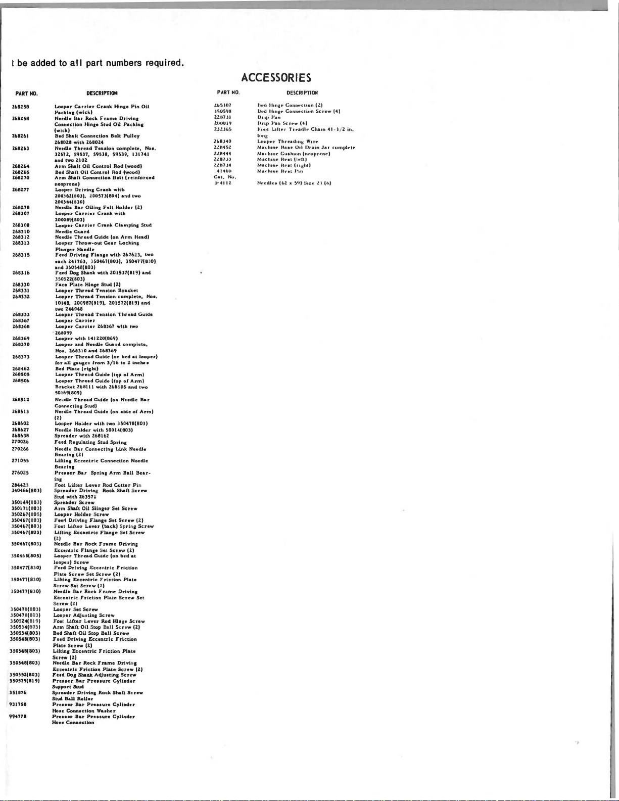
t
be
added to
PART
110.
Z68Z58
UBZ58
168161
168163
U8Z64
Zb8165
Z61Z70
168178
Zb8307
268308
268310
Z4131Z
Zb83ll
168315
Zb8316
Z68330
ZUlli
ZUlJZ
261)))
268367
161368
168369
268370
U837l
Z6846Z
268SOS
268506
Z6851Z
Z6851J
168601
Z686Z7
U86JB
Z700Z6
Z70Z66
171055
Z760Z5
Zt44
U
340466(803)
350149(
80 3)
350171(
80 3)
350U7(
10 51
350467(
80 3)
3
50467(80
H04b7(803)
350467(80
35046
1(805)
3
50477(830)
3
50477(UO)
3
50477(UOI
350471( 803)
35047 8(
803
350 5
14(
819
3
505)4(
803
350534(8031
3505411(103)
3505411(803)
150548(803)
350551(803)
350579(819)
351176
931758
994778
all
Looper
Cauin
Packlna
Nerdh
Bu
Coaneclton
(wick)
Bed
Shah
%61021
whh
Needle
Thread
lUll,
59~17.
and
two
Arrn
Shah
Bed
Shaft
Arm
Shah
11110prene)
J..ooper
Drlrin&
100.)62(.0,,, l'D051J(804)
Z00l44(130)
Needle
Bu
Looper
Carrier
Z00089(80JI
Looper
Carrier
Needle
Guard
NudJe
Thread
Looper Throw-out
PhU11er
F
••d
Drlvina
euh
Ztl76l, )S0461(80JJ,
a nd
lSOS4B(ll0l)
F
eed
Do1
35
05Z1(803)
F
ace Plalo
Looper
Thread
Looper
Thread
10148,
100987(819),
two
Z440t8
L.oopor
Thread
Looper
Carrier
Looper
Carrier
Z610~9
J..ooper
with
Looper
and
Noa,
Z68ll0
Looper
Thread
(oY
all
1•\fau
Bed
Plate
Looper
Thrud
l..ooper
Thread
Btt.ckd
50169(809)
Netrdle
Thread
Connectina
N'eeclle
Thrud
IZI
L.ooper
Holder
Needle
Holder
Spreader
Feed
Resulatln&
Neeclle
Bar
Bearins
Ufllns
Eccentr
Burlna
Preucr
Ina
.F
oot
l.Uter
S
preader
S
tud.
with
Spreader
Arm
Shalt
Looper
Holdor
r aett
)
)
)
Drivin1 Flanaa
J"'
oot
Lifter
LUttns
IZI
Needle
Eccentr
Looper
loopu)
f"
e:ed Dri
P l
ate
Screw
Llfttna
Sc
rew
Set
Netdle Bar
EcceniJ'
S
crew
(Z)
Looper Set
Loop
er
Foot L
itter L.ever
Arm Shaft
Ba4
ShAft OU
J'ud
Drivin&
Plata
Screw
L.UtlD&
Screw
(1)
Needle
Eccentric
Fud
Doa SbaDit
Pruaer
Support
Spreadar
Stud
Ball
Pruaer
Hose
Couectlon
Prauu
Ho
..
Connection
Eccentric
Sa,.
ic
Thnad
Screw
Eccentric
ic
AdJu•Una
Eccentric
Bar
Bar
Stu4
Bar
Bar
3)
3)
part numbers required.
DESCRIPTION
Crank
Hina•
Pin
(wick)
Rock
Frame Drl
Hlna•
Stud
Canoec&kln
Belt
161024
Tenalon
59Sl8,
ZIOZ
Oil
Control
011
Control
ConnecUon
Cnnk
QUina
Felt
Cnnk
Crank
Guide
(an
Gear
Handle
Flana•
with
Shank
with
201Sl1(8l9)
Hlnae
Stud
Tenalon
Tenelon
Z0157Z(819)and
Tenalon
Z68)61
l4lZZ0{86'f)
Needle
Cu.a
and
Z68l69
Guide
from
l/16
(rtaht)
Ciuide hqp
Guide
Z68ll1
Vll'lth
ZftflSOS
Guide
(on
Stud)
Culdc.
(on
with
tWo
with
50014(803)
whh
Z6816Z
Stud
Sprlns
Connectlna
(Z)
ic
Connection
Bar
Sprlna
Arm
Lever
Rod
Orivlna Rock
Z6l57
.l
Screw
Oil
SUnael'
Screw
Set
L.ever
(back) Sprl
Flanae Set
Rock
Frame
Flanae
Se t
Screw
Guide
(on
vtna Eccentric:
Set
Screw
F r i
ction
Scnw
(Z.)
Rock Fra
me
Friction Pla
Screw
Screw
Rod
Oll Stop Ball Screw
Stop
BaU
Ecuntric
(2)
Friction
Rock
Fnmo
Friction
Plate
Adjuttina
Preuure
Orivina
Rock
RoUu
Pre
..
un
Waehor
Pruaure
vlna
OU
Packln1
Pulley
complete,
S9Sl9,
Rod
(wood)
Rod
(wood)
Belt
(ninforc.d
wlth
and
Holder
whh
Clamplna
Arm
L.acklna
ZU6Zl,
JSOU7(8
(Z)
Bracket
complete,
Thread
with
rd
complete,
(on
bed
to
Z
of
(fop
of
and
Needle
aide
150418(803)
Link
Ball
Cotter
Shaft
Set
Screw
Screw
Orivina
Ill
bed
Friction
(Z)
Plate
DrlrinJ
te
Screw
Hln
a•
Screw
Friction
Plate
Drh,l
Screw
Screw
Cylinder
Shaft
Screw
Cylinder
Cylinder
011
111141
IWo
(2)
Stud
H
..
and
G"ide
twa
at
looper)
~nd~•
Arm)
Arm)
IVII'o
Bar
oC
Arm)
Needle
Neeclle
Sear-
Pi
n
crew
(Z)
na
Screw
Screw
at
Set
Screw
(ZJ
nJ
(Z)
Noa.
d)
two
Noe.
)0J
ACCESSORIES
PART NO.
lb!tUil
lr.OS11"
Zl.87
.H
lOOUIIt
ZJlJt.!t
Zb8J40
Z!H4S.Z
ZlHH<t
2ZI7H
utn.tt
<tUUII
C.u. Nu.
P<tiiZ
ltrd
lhnijr
U .. d
Hmttr
Dn1•
p,."
llnp
Van
•uul
1
..
111rr
tuna
Lf~t•rrr
Thrudmg
Mou.:hrnr
Ji,ue
Met
hint"
Cu•hwn
M.u::hu
1r Ht"el
Madunr
Hral
M.uh1n"
u ... t
Nredh.••
(bl.
DEICRIPTIOH
Cunnrn•un
C(mnrcliun
Scrrw
C<tl
Trradlr
Orl
(nruJtrrnr)
Cldtl
(nchl)
l'tn
111
!I'll
Su.r
Cham
W1r~
Urain
IZ)
Screw
.!
t
Hl
<ti
· I/ Z
in
.
Jar
c
ornplrlr
(h)
Page 46

Page 47

Page 48

.,..o
....
...
"'
0
WORLD'S
,.tlf
fiNEST
QUALITY
*
INDUSTRIAL
SEWING
MACHIN
ES
UNION
SPECIAL
maintains sales
facilities throughout the world. These offices will
aid
you
in
the selection of the right sewing
equipment for your
Special
tory trained
promptly
tion, there
serve you.
ATLANTA
BOSTON I MASS.
CHICAGO,
DALLAS,
LOS
ANGELES,
NEW
YORK,
OPA
LOCKA,
PHILADELPHIA, PA.
representatives
and
and
is
a Union Special Representative to
Check with
, GA.
ILL.
TEXAS
CAL.
N.Y.
FLA.
particular operation. Union
and
service men
are
able
to serve your needs
efficiently. Whatever your loca-
him
today.
MONTREAL,
TORONTO,
BRUSSELS,
LEICESTER,
LONDON,
PARIS,
STUTTGART,
and
service
are
CANADA
CANADA
BELGIUM
ENGLAND
ENGLAND
FRANCE
fac-
GERMANY
UNION
UNION
SPECIAL
SPECIAL
Representatives
Industrial cities
CORPORATION
GmbH, SCHWABSTRASSE
and
400
distributors
throughout
N.
FRANKLIN
33,
D-7000
In
tho
all
Important
world.
ST.,
CHICAGO,
STUTTGART
IL
60610 U.S.A.
1,
WEST GERMANY
 Loading...