

Page 1
•
INDUSTRIAL
SEWING
FINEST
QUALITY
STYLES
P260-9/108
P260-9/109
MACHINES
P260-9/1
26
P260-9/139
P260-9/141
CATALOG
NO.
HIGH
SPEED SINGLE
MACHINES
AND
CLASS P26
FOR
GENERAL BARRING
TACKING
0
NEED
LE L
OPERAT
OCKSTITC
IONS
H
P3148
UNION SPECIAL
C H I
CORPORATION
CA
GO
Page 2

Page 3
CONTENTS
DESCRIPTION...
LUBRICATION
...
...............
....
......
....... ........
................
....
...
........
..........
.............. 4
OPERATOR INFORMATION .....................
MACHINE
ADJUSTMENTS ............................ 8-21
INDEX
.....
Page
..
..
3-7
3
Bobbin ..............................
Adjusting Bobbin Winder
Case
Bobbin
Bobbin
Bobbin
Remov.a1
Case
Replacement..................... ... .... 7
Case
Threading
Bobbin Winding..
Description.....
General
Special
Feed
Mechanism Adjustment.. ........................ 14-19
..
................................................
Characteristics..
Features
Driving Gear s...
.................................... 6-7
.. .........................
......................
...
............................. 7
..
..........................
......
...
..................... 3
.................
...
...
....
.......................................... .
Lateral Linkage {Barring and T a eking
...
Machines). .............................
Lateral
Machines).....
Linkage (Button Sewing
...
.................
.......
.....................
Longitudinal Linkage {Barring and
Tacking Machines)..........................
Length of
Tack...
....
..........
..........................
Longitudinal Linkage {Button Sewing
...
Machines)
Timing Lateral
Timing Longitudinal
Width
.....................................................
Feed
......
...
...................... 18, 19
Feed
......................
of Tack....................................
Knife Actuating and Clamp
Lifti~;~g
Safety Interlock ..........................
Tension
Adjustments. .............
Releaser
............
......................
...
...................
..............
...
......... 6
...........
...
...........
...
....
.......
......
..............
...
.......
......
...
...
...
..
..
18,
12-13
....
..
Page
.. 6
...
14
14
17
16
18
18
19
16
..
12
12
Page
Thread
6
Work
Knife Removal and Replacement.. .........
Wiper
.......... .
.......................................
Clamp Foot Lifter ........................
.....
13
........ 13
...
...
..
20
Knife Timing and Positioning ........................ 19-20
Positioning
Timing .......... .........................
3
Lubrication...... .......
Daily Care............................................
3
Week
Machine Threading ...........
Needles
........
...
.............
...
...............................
ly
Care ........................ ....
..........
...
...........................................
.............................. 20
........................... 19
........
............ 4
................
.........
............................
...
..
4
.......... 4
..
5
............ 5
Setting the Needle ............................................ 5
Sewing Meehan
Needle Bar Height ...............................
Positioning Shuttle Driver ....
Shuttle Timing ...
Speed .....................................................
Stop Motion Adjustments ...................
Arm
Shaft ...
Engaging
Starting Lever
Starting Lever
Tripping Linkage
Motion Brake ......
Stop
Thread
Tens
Bobbin Thread
Needle Thread
ism
Adjustments .......
...........
....
...
...........
....
...........
Arm .........
..
....
Arm
............
.........................
..............
Stop
.......
...
..........
...
....
...................
......
............................ 9
...................
...
..............
ion Adjustments .........
..
.................................... ......
..
................
......
.......
...
.. ..............
...
........
..........
...
...........
........
........
................... 4
........
.......
..........
.............
....
......
......
......... 8
..........
........ 10
..............
....................... 7
...
...
...........
8-11
.... 8
..
...
...
..
21
21
21
21
9
11
7
7
2
Page 4

Page 5
DESCRIPTION
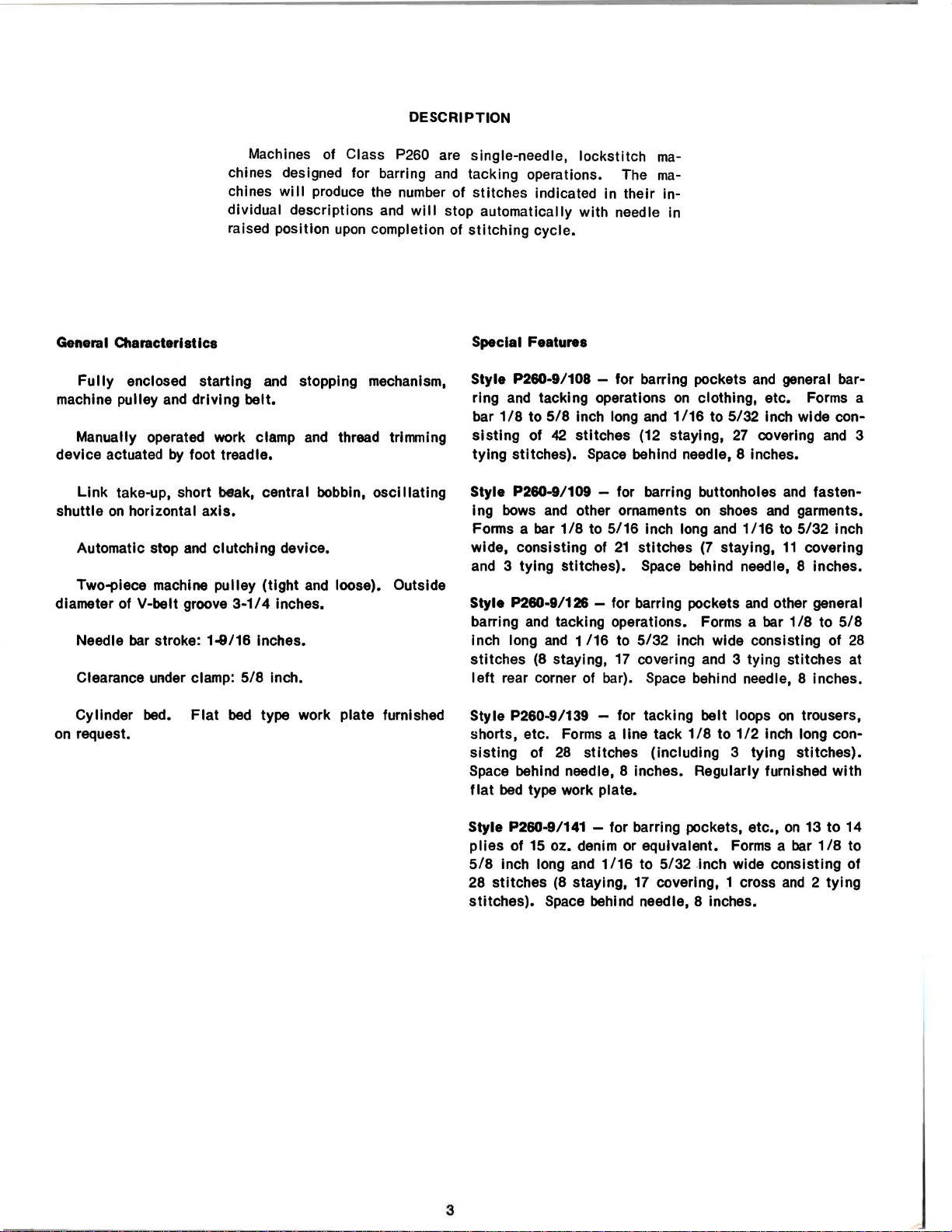
Machines of Class P260 are single-needle, lockstitch
chines designed for barring
chines
dividual descriptions
raised position
General
machine pulley
device actuated
shuttle
diameter of V-belt groove
Characteristics
Fully
Manually operated work clamp
Link
Automatic stop
Two-piece machine pulley (tight
enclosed starting
and
driving belt.
by
foot treadle.
take-up, short beak, central bobbin,
on
horizontal
axis.
and
clutching device.
3-1/4
bar
Needle
Clearance under clamp:
stroke: 1-9/16 Inches.
5/8
will
produce the
upon
and
stopping mechanism,
and
thread trlnvning
and
loose). Outside
inches.
Inch.
and
number
and
completion of
oscillating
of stitches indicated in their In-
will
stop automatically with needle In
ma-
tacking operations. The
stitching
Special Features
Style P260-9/108
ring
bar
sisting
tying stitches).
Style P260-9/109 - for barring buttonholes
1
ng
Forms a bar
wide, consisting of
and
Style P260-9/126 - for barring pockets
barring
Inch long
stitches
left
cycle.
- for barring pockets
and
tacking operations
1/8
to
5/8
Inch long
of
42
stitches (12 staying,
Space
bows
and
other ornaments
1/8
to
5/16
3 tying stitches).
and
tacking operations. Forms a bar
and
1/16
(8
staying, 17 covering
rear corner of bar).
ma-
and
on
clothing, etc. Forms a
and
1/16
to
5/32
27
behind needle, 8 inches.
on
shoes
21
to
5/32
Inch long
stitches
Space
Space
and
1/16
(7
staying,
behind needle, 8 inches.
and
inch wide consisting of
and
3 tying stitches at
behind needle, 8 inches.
covering
general bar-
Inch wide con-
and
and
fasten-
and
garments.
to
5/32
inch
11
covering
other general
1/8
to
5/8
28
3
Flat
bed
Cylinder bed.
on
request. shorts, etc. Forms a line tack
type work plate furnished Style P260-9/139 - for tacking belt loops
sisting
Space
flat
Style P260-9/141 - for barring pockets, etc.,
plies
5/8
28 stitches
stitches).
of
28
stitches (including 3 tying stitches).
behind needle, 8 inches. Regularly furnished
bed
type work plate.
of 15 oz. denim or equivalent. Forms a
Inch long
and
1/16
(8
staying,
Space
behind needle, 8 inches.
1/8
to
to
5/32
.Inch wide consisting of
17
covering, 1 cross
on
1/2
Inch long con-
on
and
trousers,
13
to
bar
1/8
2 tying
with
14
to
3
Page 6
LUBRICATION
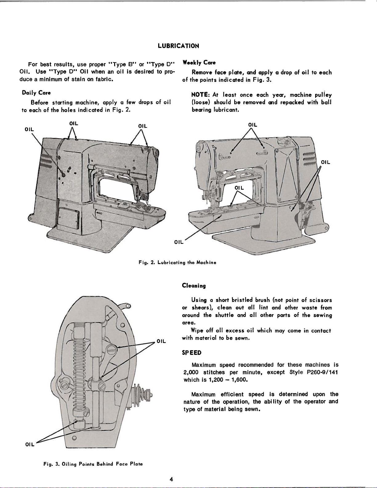
For best results, use proper
Oil.
Use
"Type
duce a minimum of stain
D"
Oil
when
on
fabric.
Daily Care
Before starting machine, apply a
to each
of
the
holes
indicated in Fig. 2.
"Type
an
oil
B"
or
"Type
is
desired to pro-
few
drops of oil
D"
Weekly Care
of
Remove
the
NOTE:
face
points indicated
At
(loose) should
bearing lubricant.
plate,
least
and apply a drop of oil to
in
Fig.
3.
once
each year, machine puliey
be
removed
OIL
md
repacked with ball
each
Fig.
2.
Lubricating
OIL
the
Machine
Cleaning
Using a short
or
shears),
around
the
clean
shuttle
bristled
brush {not point of
out all lint and other
and
all
other parts of
scissors
waste
the
sewing
area.
Wipe
off all
with material to
excess
be
sewn.
oil which
may
come
in
contact
SPEED
Maximum
speed
recommended
for these machines
2,000 stitches per minute, except Style P260-9/141
which
is
1,200-
Maximum
nature of the operation, the
type of material being sewn.
1,600.
efficient
speed
is
ability
determined
of the operator
upon
from
is
the
and
OIL
Fig.
3. Oil ing
Points
Behind
Face Plate
4
Page 7
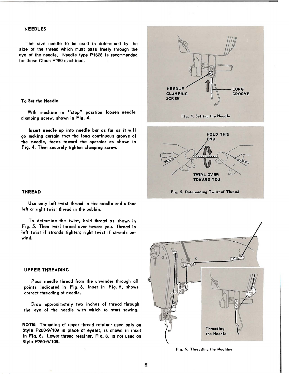
NEEDLES
The size needle to be used
is
determined
by
the
size of the thread which must pass freely through the
is
eye of the needle. Needle type P1628
recommended
for these Class P260 machines.
To Set the
With
clamping screw, shown in
Insert
go making certain
the
Fig.
Needle
machine in 11stop"
needle
needle,
4.
Then
up into
faces
securely
position loosen
Fig.
4.
that
toward
needle
the
bar
as
long continuous groove of
the
operator
tighten clamping screw.
for
as
needle
as
it
shown
will
in
NE E
DLE
CLAMPING
SCREW
Fig.
4.
Setting
TWIRL
TOWARD
1~1:--
the Needle
HOLD THIS
END
/
OVER
YOU
-
LONG
GROOVE
THREAD
Use
only left
left or right
To determine
Fig.
5.
Then twirl thread over toward you. Thread
left
twist
if
twist
strands
twist
thread
thread
the
in
twist,
tighten; right
in
the
the bobbin.
hold thread
twist
needle
if
wind.
UPPER THREADING
Pass
needle
points i
correct
ndicated
threading of
Draw approximately two
the
eye
of
thread
in
from
Fig.
6.
needle.
inches
the
needle with which to
the
unwinder through all
Inset
in
of thread through
NOTE: Threading of upper thread retainer
Style P260-9/109 In place of eyelet,
in
Fig.
6. Lower thread retainer,
Fig.
is
6,
Style P260-9/109.
and either
as
shown
in
is
strands
Fig.
start
used
6,
shows
sewing.
only
un·
shown in inset
is
not
used
on
on
Fi • 5.
Fig.
Determining Twi
Threadin
th
e Needle
6.
Threading
the
st
of
Thread
g
Machine
5
Page 8
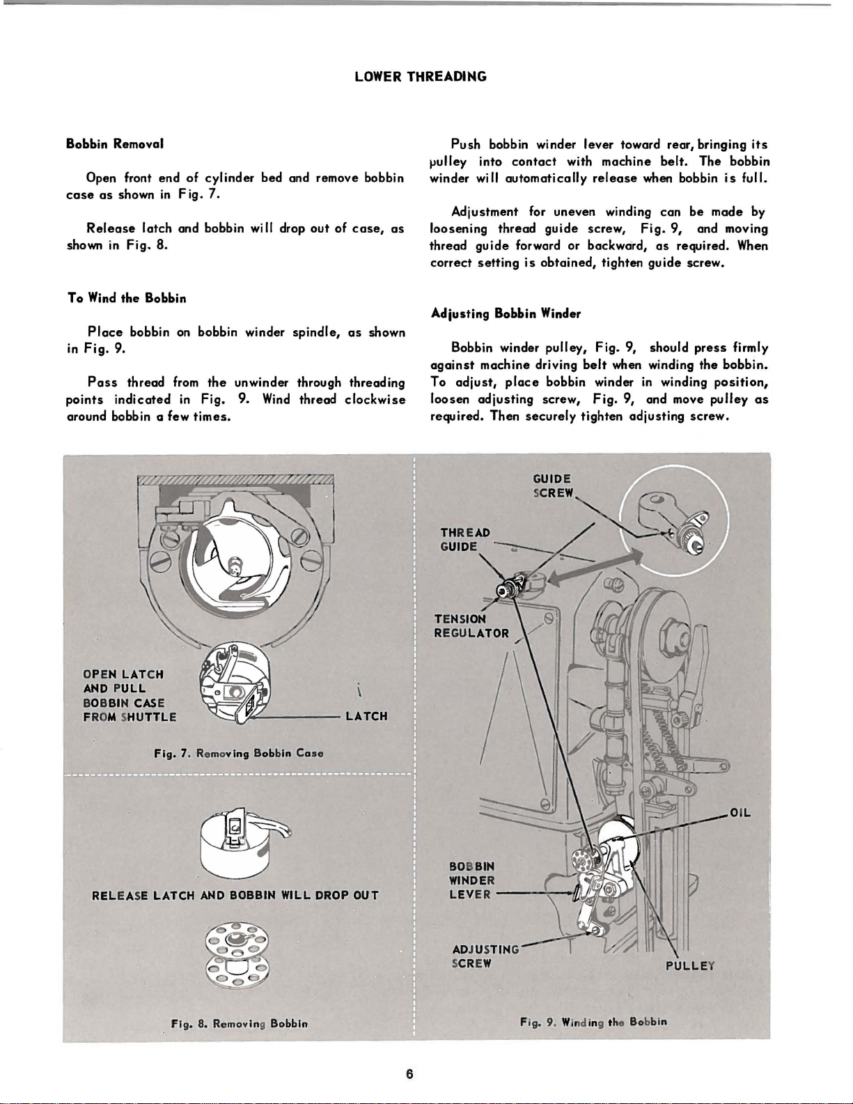
LOWER THREADING
Bobbin Removal
Open
front end
case
as
Release
shown
To
Wind
Place
in
Fig.
Pass
points
shown
in
9.
indicated
latch
Fig.
the
bobbin
thread
in
Fig.
and bobbin
8.
Bobbin
on
from
in
around bobbin a few
of
cylinder
7.
wi
bobbin winder
the
unwinder through threading
Fig.
9.
times.
bed and remove bobbin
II
drop
out
of
case,
as
Wind
spindle,
thread
as
shown
clockwise
Push
bobbin winder lever toward rear, bringing
.,ulley into
winder will
contact
with machine
automatically
release
Adjustment for uneven winding
loosening
thread
correct
thread
guide
setting
guide
forward or backward,
is
obtained,
screw,
Adiusting Bobbin Winder
Bobbin winder
against
To
loosen
machine driving
adjust,
adjusting
required. Then
pulley,
place
bobbin winder
screw,
securely
Fig
belt
Fig.
tighten adjusting
belt.
when bobbin
can
Fig.
as
tighten
guide
. 9, should
when winding
in
winding
9, and move
its
The bobbin
is
full.
be
made by
9, and moving
required.
When
screw.
press
firmly
the
bobbin.
position,
pulley
as
screw.
OPEN
LAT
PULL
BIN CAS
CH
E
Fig.
LATCH
7. Remo
Fig
ving Bob
AND
BOBBIN
. 8. Removing Bobbin Fig. 9. Winding the Bobbin
bin Ca
WILL
se
DROP
OUT
BOBBIN
WINDE
R
LEV
ER
--
AD
J USTING
CR
EW PULL EY
S
AND
BOB
FROM SHUTTLE
REL EASE
6
~:--t/l.i
'::lh~
Page 9
PULL THRE
INTO
UNDER TENSION
SPRING
SLOT
AD
AND
THREAD
PULL
UP
INTO
POSITION
FINGER
Fig. 10. Re
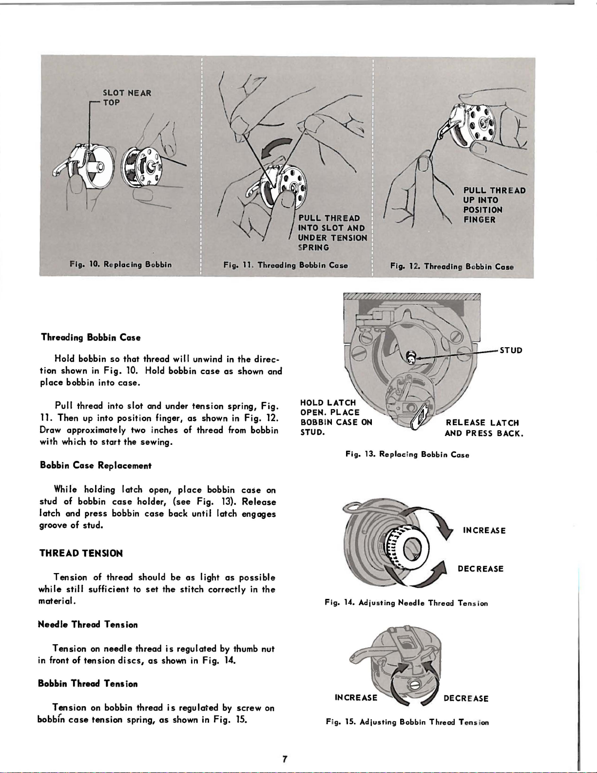
Threading Bobbin
Hold bobbin
tion shown
place
bobbin into
Pull
thread into
11. Then
up
placing Bobbin
Case
so
that thread will unwind
in
Fig.
10. Hold bobbin
case.
slot
and under
into position finger,
case
tension
as
shown
Draw approximately two inches of thread
with which to
Bobbin
While holding latch open,
stud of bobbin
latch and
Case
press
start
the sewing.
Replacement
case
holder,
bobbin
case
place
(see
bobbin
Fig. 13).
back until latch
groove of stud.
Fig. 11.
in
the
as
shown and
spring,
in
Fig. 12.
from
case
Release
engages
Threading
direc·
Fig.
bobbin
on
Bobbin
Case
HOLD
LATCH
OPEN. PLACE
BOBBIN
STUD
CASE
.
Fig.
Fig.
ON
13.
Replacing Bobbin
12. Thre
adin
g Bobbin
RELEASE
AND
PRESS BACK.
Case
INCREASE
Cas
e
STUD
LATCH
THREAD
while still sufficient to
material.
Needle
Tension
in front of
Bobbin Thread
Tens
bobb(n
TENSION
Tension of thread should be
set
the
Thread Tension
on
needle
tension
Tens
ion on bobbin thread
case
tension spring,
thread
discs,
ion
as
is
shown
is
as
shown
as
light
stitch
correctly
regulated
in
Fig.
regulated
in
as
by
14.
by
Fig.
possible
in
the
thumb nut
screw
on
15.
Fig.
14. Adjus
Fig. 15.
7
ting
Adjusting
DECREASE
Needle
Thread
Ten
DECREASE
Bobbin Thread Tens i
s ion
on
Page 10
ARM
SHAFT
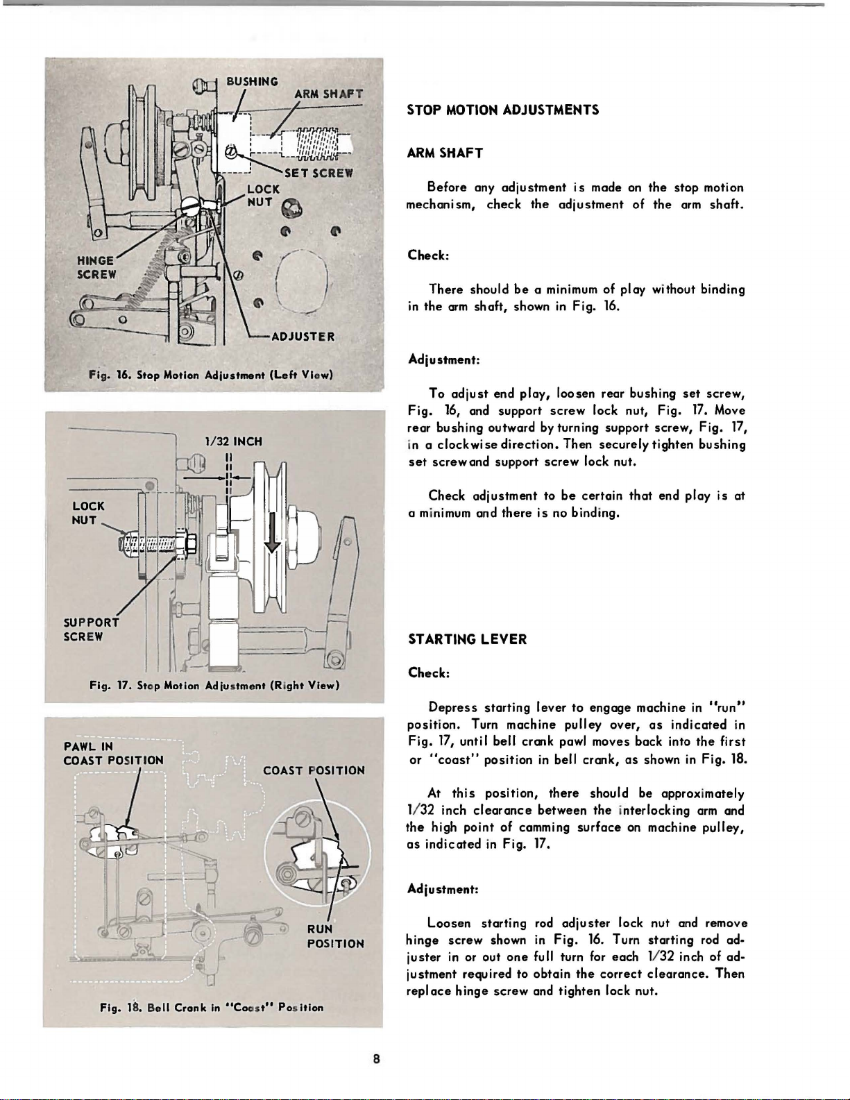
STOP MOTION ADJUSTMENTS
ARM
SHAFT
Fig. 16. Stop Motion
LOCK
HUT
Adjustment
1/32 INCH
--
ADJUSTER
(Left Vlow)
Before any
mechanism,
Check:
There
in
the
arm
Adjustment:
To
adjust
Fig.
16, and support
rear bushing outward by turning support screw,
in a
clockwise
set
screwand
Check
a minimum and
adjustment
check
should
be
shaft,
shown
end
play,
direction.
support
adjustment
there
is
made on
the
adjustment
a minimum of play without binding
in
Fig. 16.
loosen rear bushing
screw
screw
to
is
lock nut,
Then
securely
lock nut.
be
certain
no binding.
of
that
the
stop
the
arm
set
Fig.
tighten
end play
motion
shaft.
screw,
17.
Move
Fig.
bushing
is
17,
at
Fig.
17. Stop Motion Adjus
PAWL
IN
COAST POSITION
Fig.
18. B
ell
Crank
tment
(Ri
ght
in
"Coast" Pos ition
View)
RUN
POSITION
STARTING
Check:
Depress
position.
Fig.
17, unti I bell crank pawl moves back into
or
"coast"
At
1/32
the
high
as
indicated
Adjustment:
Loosen
hinge
juster
justment required to
replace
LEVER
starting
Turn machine pulley over,
position
this
position,
inch
clearance
point
in
starting
screw
in or out
hinge
shown
screw
lever
to
in
bell
there
between
of
camming
Fig. 17.
rod
adjuster
in
Fig.
one
full turn for each 1/ 32 inch of adobtain
and
tighten
engage
crank,
should be approximately
the
surface
16.
Turn
the
correct
lock nut.
machine
as
as
shown in Fig. 18.
interlocking
on machine
lock nut and remove
starting
clearance.
in
"run"
indicated
the
arm
pulley,
rod ad-
Then
in
first
and
8
Page 11
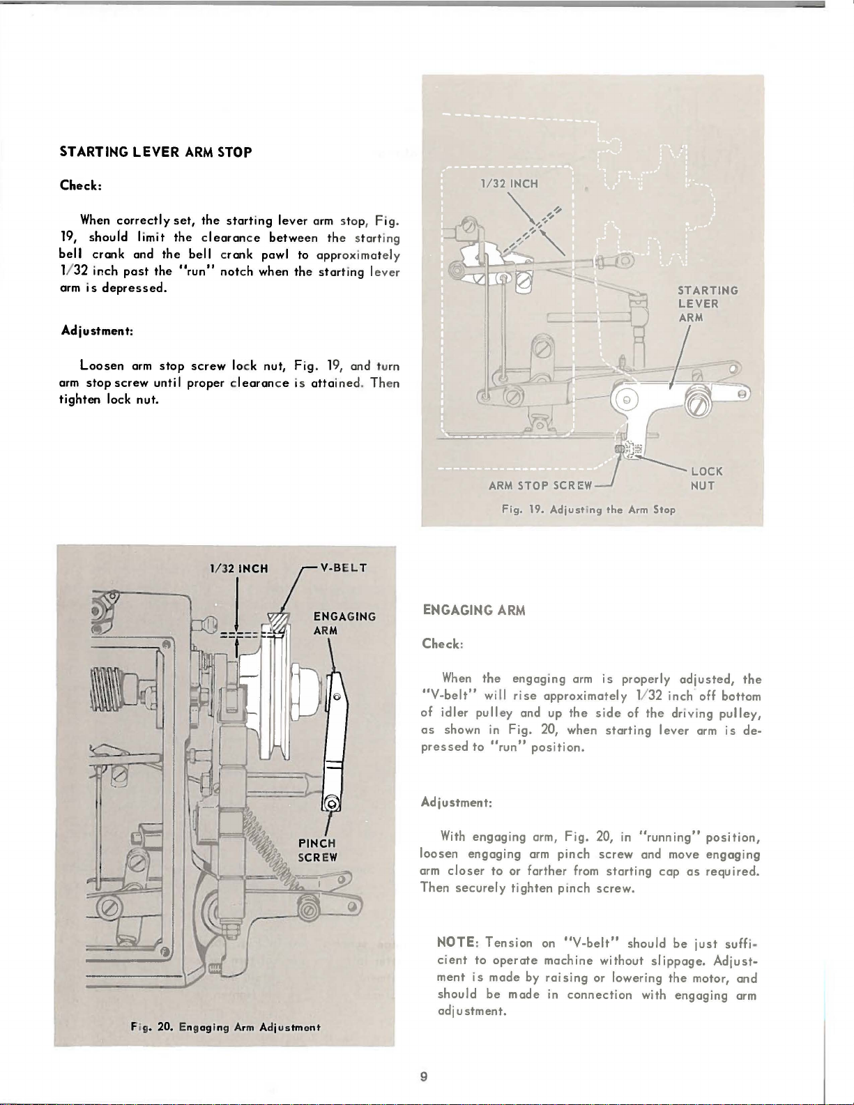
STARTING
Check:
When
correctly
19,
should
bell
crank
1/
32
inch
arm
is
depressed.
Adjustment:
LEVER
limit
and
past
ARM
set,
the clearan
the
bell crank
the
"run"
STOP
the
start
not
ch when th e st
ing
leve
r arm stop,
ce
betw
een
th e st
pawl to appr oximately
art
ing l
Fig
art
ever
.
ing
Loosen
arm
stop
tighten
arm
screw
lock nut.
stop
screw
unti I proper c
loc k
learan
nut, Fig
ce is
. 19, and tu
atta
ined. Then
rn
ENGAGING
Check:
When
"V-belt"
of
idler
pulley
as
shown
pressed
to
ARM
the
will
in
"run"
Fig.
19.
Adjusting
engaging
rise
approximately 1132 inch off bottom
and up
Fig.
20, when
arm
the
the
is
properly
side
starting
Arm
of
Stop
the
driving
lever
position.
adjusted,
pulley,
arm
is
the
de-
Adjustment:
With
engaging
loosen
arm
Then
engaging
closer
securely
NOTE:
cient
ment
should
to
Tension
to
operate
is
made
be
adjustment.
Fig.
20.
Engaging Arm Adjustment
9
arm,
arm
or
farther
tighten
by
made
Fig.
pinch
from
pinch
on
"V-belt"
machine
raising
in
connection
20,
in
"running"
screw
and move
starting
screw.
should
without
slippage.
or lowering
with
cap
as
be
the
engaging
position,
engaging
required.
just
suffi·
Adjust-
motor,
and
arm
Page 12
STOP
MOTION ADJUSTMENTS
(
CONNECTING
ROD }
ROCK
PINCH
SUPPORT
I
SHAFT
SCREW
SET
SCREW
(continued)
Fi
g.
___ /
21.
Adjusting tho
Tripping
Link
ogo
I
r
--------
1
1-------·
1
I
__
..
,
--
- -
- ----
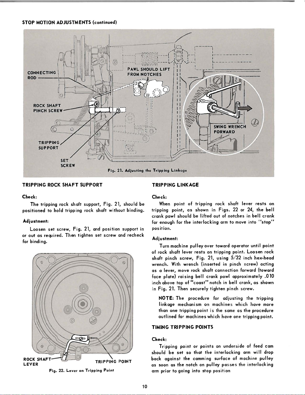
TRIPPING
Check:
The
tripping rock
positioned
Adjustment:
Loosen
or
out
as
for binding.
ROCK
SHAFT
to
hold tripping rock
set
screw,
req.~ired.
SUPPORT
shaft
Fig. 21, and
Then
tighten
support,
shaft without
set
Fig
. 21, should
position
screw
binding.
support
and
recheck
be
in
TRIPPING
Check:
When
tripping
crank
far
enough
position.
Adjustment:
Turn
of
rock
shaft
wrench.
as
a lever, move rock
face
inch
above
in
Fig.
NOTE:
linkage
than
outlined for mach i
TIMING
point
point,
pawl
machine
shaft
pinch
With
plate)
21. Then
The
one
TRIPPING
LINKAGE
should
for
screw,
raising
top
mechanism
tripping
of
as
be lifted
the
interlocking
pulley
lever
wrench
of
"coast"
securely
procedure
tripping
shown
rests
Fig.
bell
point
nes
POINTS
rock
in
out
over
toward
on tr ipping point.
21,
using
(inserted
shaft
connection
crank
notch
tighten
for
on
machines wh
is the same
which
shaft
Figs.
22 or 24,
of
notches
arm
to
operator
5/ 32 inch
in
pinch screw)
pawl
approximately
in
bell crank,
pinch screw.
adjusting
have
one tripping
lever
rests
the
in
bell
move into
forward (toward
ich
as
the
until
Loosen
hex-head
as
the
tripping
have
procedu
"stop"
acting
shown
point.
on
bell
crank
point
rock
.010
more
re
Check:
Tr ipping poi
Fig.
22.
Lev
er
on
Tripping
Point
should
back
as
arm
against
soon
prior
be
set
as
the
to
going into
10
nt
so
the
notch
or
points
that
cammi
on
on
undersi de of feed cam
the int
stop
erlocking
ng
surface
pulley passe s the inte
posit
ion
of
arm
mach
wi
II
ine
pulley
rlocking
drop
Page 13

Adjustment:
On
machines
point shown in
and move tripping
or to
the
left
to
more than
be
adjusted
On
point
three
STOP
one
tripping point,
independently.
machines
shown in
tripping point
MOTION BRAKE
CLEARANCE
Check:
The
clearance
Fig.
25, and
proximately
1/
the
32
position.
equipped
Fig.
point
set
equipped
Fig.
with feed
23, loosen tripping
to
the
trip
off
with
24, it
is
screws, then,
between
machine
the
pulley
inch when
right to trip
later.
On
each
tripping
feed
necessary
set
stop
motion
(tight)
the
machine
cams
with tripping
machines
cams
with
to
the
same
should
point
off
point
loosen
as
brake
is
in
screw
sooner,
having
must
tripping
the
above.
shoe,
be
ap-
"run"
Fig.
23.
Tripping
Point
on
Cast
Iron
Cam
Adjustment:
With
machine
stud
set
screw,
the
proper
clearance
screw.
PRESSURE
Check:
The
brake
pressure,
and material being
machine
ning
from
at
excessive
going i
parts.
Adjustment:
Loosen
rurn
adjusting
ward for
adjusting
screw
less
pressure.
in
"run"
Fig.
25, and turn
is
depending
sewn,
should
nto
full
speed;
screw
inward for more
Then tighten p.inch
position,
eccentric
attained.
Then
upon machi
be
adjusted
stop
position
to
avoid damaging
pinch
screw,
loosen
stud
tighten
to
while
Fig.
pressure,
eccentric
unti I
set
ne
speed
prevent
run-
machine
25,
and
or out-
screw.
ECCE
ADJUS
SCREW
NT
TIN
Fig.
RIC S
G
24.
TUD
Tripping
Point
on
Phenolic
Cam
NOTE: Stop motion brake
adjusted
braking power
about
once
due
to
surface.
adjustment
a month,
wear or
to
offset
glazing
should
any
of
the
be
re-
loss
in
braking
Fi
g. 2 • Adjust ing the Sto M
11
otion Brak
Page 14

SAFETY
INTERLOCK
KNIFE
ACTUATING AND CLAMP
TE
LIFT
ING ADJUSTMENTS
NSION
RELE
ASER
Check:
The
safety
vent
the
clamp from
operating
when
the
and will
clamp
Adjustments:
With
knife
cam,
depress
into
running
pinch
screw,
arm with
lifting
taining
that
tighten
screwdriver,
lug
this
the
knife
the
LIFTING
PINCH
interlock,
is
roller
starting
position.
Fig.
against
position
roller
pinch
ARM
SCREW
being
prevent
lifted.
at
lever
26, and
back
of
is
screw.
when
lifted
the
the
clear-out
to
Loosen
lift
as
shown in
of
the
in
against
correctly
while
machine
place
knife
up on
bell
lifting
the
slot
starting
bar
clamp
Fig.
crank.
lug,
the
set,
wi
II
pre-
machine
from running
in
the
feed
bell
crank
driving
lifting
26,
lever
lever
bringing
While main-
make
certain
cam and
then
is
Check:
When
work c I amp is
ment
of
the c lamp
the
need
le
thread
needle thread
Adjust
ment:
Loosen the
and m
ove
the
set sc
screw,
o
sc
and
until
posi
Make
fo
rew.
Fig. 27, and
ut
of th e rock sh aft approx i
rew.
N
ex
t, loos
push upw
ten
sio
n dis cs
tion w
hile
certain
rward shou
.---
- - - -
.
tens
entire
Then
en
the
ard on
tightening
that
lder
on
lifting
raised,
bar,
tens
ion
ion
regulator
regulator
loosen
set
lifting
lifting arm
lifting
just
begin
the
lifting
the
rock
--
the
first
Fig.
27,
discs,
releasing
set
all
the
the lifting
link
so
mately 1/32
pinch
bar,
as
shown in
to
release.
the lifting
arm
is
shaft.
INTERLOCKING
ARM
upward move·
should
tension
screw,
way in.
link
connection
that
it
inch.
screw,
Maintain
arm
pinch
up
against
separate
on
Fig.
27,
Tighten
projects
Tighten
Fig.
26,
Fig.
27,
tliis
screw.
the
LIFTING
BACK
OF
Ll
FTING
LUG
BELL
CRANK
LUG AGAINST
BELL
CRANK
---
-
CLAMP
LEVER
--'
LIFTING---"
DRIVING LEVER
SC
PINCH
REW
~-
--
-NOTCH
Fig.
26.
Adjusting
the Safety Devi
ces
12
Page 15
LIFTING
SCREW
------,
LINK
i-ft
TENSION
DISCS
I
Fig.
28.
Adjusting
Foot
Lifter
CLAMP
BAR
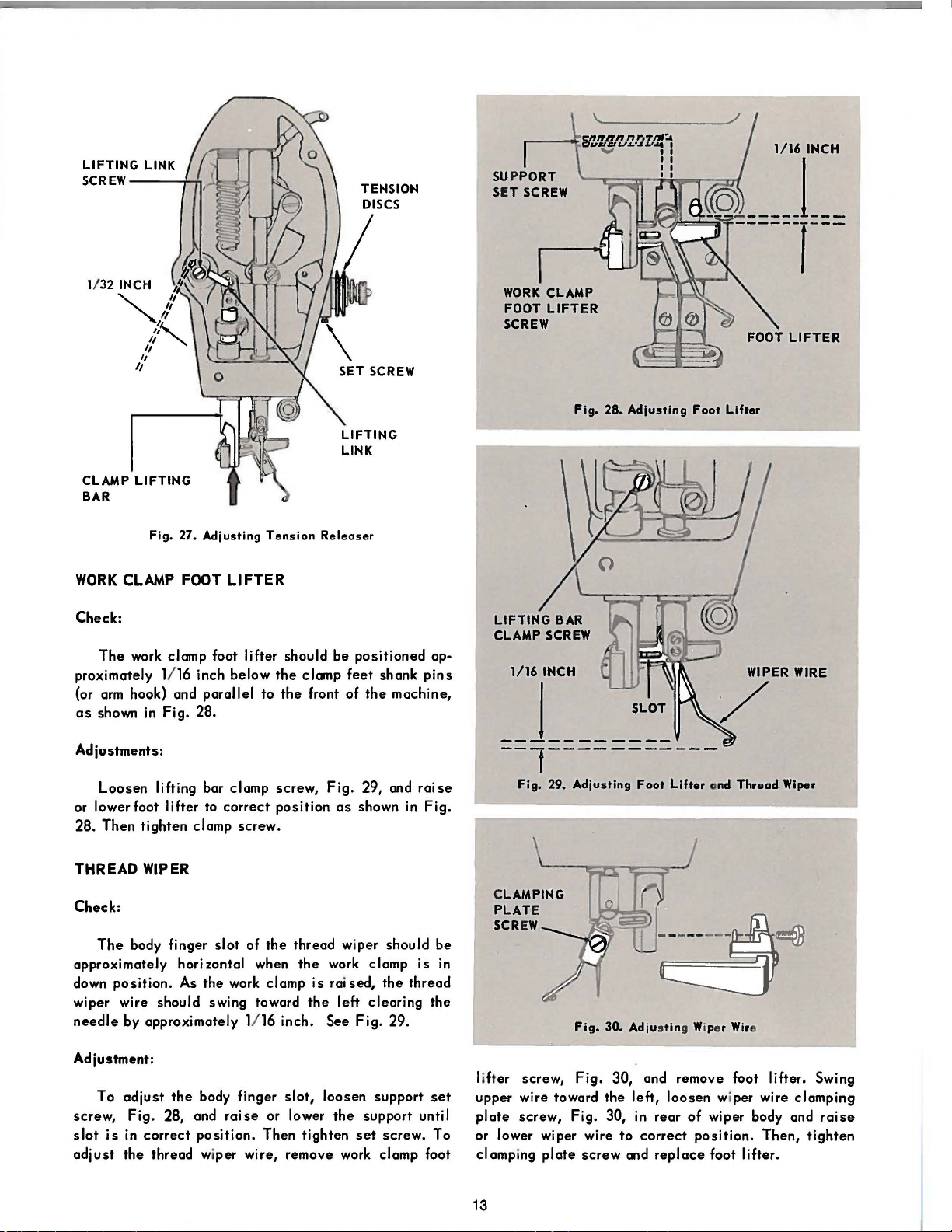
WORK
Check:
proximately 1116 inch below
(or
as
Adjustments:
or lowerfoot lifter to
28. Then tighten clamp screw.
THREAD
Check:
LIFTING
Fig.
27.
Adjusting
CLAMP
The
work clamp foot lifter should be
arm
hook) and parallel to
shown
Loosen
FOOT
in
Fig. 28.
lifting bar clamp screw,
WIPER
Tension
LIFTER
correct
the
clamp
the
front of
position
Releaser
positioned
feet
Fig.
as
shown
shank
the
machine,
29, and
in
ap-
pins
raise
Fig.
1/16
INCH
__
j_
__ l __________
______
Fig.
29.
Adjusting
Foot
_
Lifter
_
ond
Thread
Wiper
The
body finger
approximately horizontal when
down
position.
wiper wire should swing toward
needle
Adjustment:
screw,
slot
adjust
by approximately 1116 inch. See
To
adjust
Fig.
28, and
is
in
correct
the
thread wiper wire, remove work clamp foot
As
the
the
body finger
position.
slot
of
the
work clamp
raise
or lower
Then
thread wiper should
the
work clamp
is
raised,
the
slot,
loosen support
the
tighten
the
left
clearing
Fig.
support unti I
set
screw. To
29.
be
is
in
thread
the
set
lifter screw,
upper wire toward the left, loosen wiper wire clamping
plate
screw, Fig. 30,
or lower wiper wire
clamping
13
plate
Fig.
30.
Adjustin
Fig.
30, and remove foot lifter. Swing
to
screw
and
in
rear
correct
replace
g Wiper
Wir
of
wiper body and
position.
foot lifter.
e
Then,
raise
tighten
Page 16

FEED
MECHANISM ADJUSTMENTS
FEED
Check:
marks on
shaft
31, and
driving
DRIVING GEARS
When
the
machine
the
cam supporting
pinion
there
gear
should
gears.
should
be
is
in
be
aligned,
a minimum
stop
position,
gear
and
as
shown in
of
play
the
the
timing
vertical
Fig.
between
Fig.
31.
Alignment
of
Timing
Morks
NOTE:
gear
with
If
for any
are
removed, make
the
timing mark on
reason
with timing mark on pinion
Adjustment:
the
worm
the
be
in
arm
vertical
excessive
the
two
worm
forward
gear
spot
equally
casting
shaft
To remove
worm,
32) and
loosen
move
When
tical
shaft,
32, should
opening
gear
and
aligned.
To remove
pinion
gear
through
loosen
the
Then, by
gear
screw, turn
only
the
gears.
gear
Tighten the
sc
rew.
excessive
and cam supporting
hole
in
center
supporting
means
of the
the
bracket
minimum amount
socket
the
feed cam and supporting
certain
the
supporting
gear.
pi
ay between
screws
and
on
is
properly
set
in
shaft.
screws,
accessible
when
the
pini'on
play
gear
between
of supporting
gear
bracket
"hex"
head on
(which is
of
play
head
screw
they
are
replaced
gear
aligning
worm
gear
and
worm
(see
inset
Fig.
assembled
shown
through
on
in
the
verFig.
side
feed cam supporting
timing marks
vertical
gear,
insert
gear
socket
head
the
eccentric)
exists
between
inside
screw
supporting
supporting
are
shaft
wrench
and
screw.
unti I
the
SHOULD
ACCESSIBLE
BE
EQUALLY
LINKAGES ON BARRING
FEED
AND
TACKING MACHINES:
CENTERING
Check
:
The
wi
II ensure
LATERAL
lateral
that
changed, it will
of
the
throat
plate
Fig. 32. Adjusting t he
Feed
Driving Gea rs
14
FEED
feed
linkage,
when the length
change
needle
in
hole.
size
when corre
of
equally
ctly
bar or
on
both s
adjus
tack
ted,
ide
is
s
Page 17

Adjustment:
First
determine
lation
to
the
be
can
has
returned
been made,
clamping foot,
clamping foot so
the
to
its
e.
g.,
engage
turn pulley over toward
until
needle
over toward
Leave
will
indicate
To
screw
tion feed
across
aligned
At
arm
and
in
Fig.
position.
screw.
pinch
just
punctures
left
side
paper
under the clamp during
the
original
adjust,
loosen
and driving arm pinch screw,
plate
carrier bar so
the
cylinder
with
the
needle).
this
position,
the
driving arm should
33. If
Then
the
necessary,
tighten
position
that
original
position
insert a piece
machine
the
'tight
side
the
paper, then turn pulley
of machine to
position
lateral
pivot driving arm pinch
it
(or
center
lateral
feed
be
move
linkage
the
lateral
of
the
needle
the
feed
carrier
after
adjustment
of paper under
into
"run"
of machine slowly
raise
the
adjustment
of
the
needle.
Fig.
33, and
is
centered
of clamping
rock
shaft
parallel,
to
as
obtain
pivot driving arm
in
re-
bar
position,
needle.
as
this
posi-
laterally
feet
is
driven
shown
this
Next, return feed
(A
check
puncture
the
driving
TO
ADJUST LENGTH
can
hole
arm
Adjustment:
Loosen
and
the
length of
length of
tighten
slide
stud
the
stud
tack,
nut.
NOTE: After this
necessary
to
the
needle
LATERAL
carrier
be
made by lowering
previously
pinch
lateral
toward front of
tack
(across
slide
stud toward rear of machine.
bar to
made in paper.) Then
screw.
OF
TACK
driving
arm
machine
the
bed). To
adjustment
to
adjust
the
feed
carrier
as
instructed
FEED.
its
original
the
position.
needle
into
tighten
stud nut,
Fig.
to
increase
decrease
33,
the
Then
is
made, it may
bar
in
relation
under CENTERING
be
FEED
PLATE
CARRIER
BAR---.
~
:::::!
~
.-----~-PINCH
.-------A
------
LATERAL
DRIVING ARM
S
CREW
DRIVEN
RM
DRIVING
ARM
PIVOT
Fi g. 33. Adjus t ing La tera l F
eed
Link
15
age
Page 18

FEED
LINKAGES
ON
BARRING
AND
TACKING MACHINES
(continued)
DRIVING
PINCH
STUD
----
ARM
SCREW
------
DRIVING
STUD
-+-
---',.
f
ig.
34,
Adjusting
Longitudinal
Feed
Linkag
e
ARM
NUT
CENT~RING
LONGITUDINAL
FEED
With machine
Check:
The
longitudinal feed, when
will
insure
changed,
ward
from
the
the
that
feed
when
plate
throat
the
plate
backward preventing the
width (bight)
moves
the
needle
needle
correctly
same
distance
hole
as
from
striking
adjusted,
of
tack
it
moves
for-
the
is
ley
slowly
not
strike
movement.
TO ADJUST
Adjustment:
while checking to
the
WIDTH
clamping foot.
Adjustment:
Through
loosen
screw,
the
Fig.
backward in
tighten
the
access
longitudinal rock
hole
in
right
shaft
side
of upright arm,
driving arm pinch
34, and move clamping foot forward or
correct
relation to
the
needle.
Then
pinch screw.
re-
Loosen
34, and
to
increase
slide
NOTE: After
necessary
the
GITUDINAL
slide
stud
needle
to
the
stud
the
the
to
as
16
in
"run"
position,
see
that
clamping foot during i
OF
TACK
longitudinal driving
to
the
right (facing rear of machine)
width of
left.
this
adjust
instructed
tack.
Then
adjus
the
tighten
tment
feed
under CENTERING LON-
To
decrease
is
plate
arm
the
FEED.
turn machine pul-
the
ts
stud nut,
stud
made,
in
needle
longitudinal
does
the
width,
nut.
it
may
relation
Fig.
be
to
Page 19

FEED LINKAGES
ON
BUTTON
SEWING
MACHINES
Lateral
adjusted
buttons or when
LATERAL
and longitudinal
when changing
the
hole spacing
FEED
Check:
The
lateral feed linkage, when correctly adjusted,
will
ensure
t,ance on one
moves on
increased
To
Obtain Equal Distance:
Remove cylinder
Insert button to
chine
until
needle
into
that
side
the
other
or
decreased
,.run"
is
just
the
feed plate moves
of
the
side.
as
arm
be
position and rotate machine pulley
above button,
Loosen lateral pivot driving
arm
driving
plate
inder)
so
pinch screw, Fig. 36, and position feed
that
as
button
shown
in
Fig. 36.
is
feeto
linkages should
from
throat
This
two or
in
plate
equal
from
the
buttons change.
the
same
needle
hole
distance
four hole
dis-
as
can be
required.
cover.
sewn into clamp, engage ma-
as
shown
arm
centered laterally
in
Fig. 35.
pinch screw and
(across
cyl-
be
it
At
this
position, the lateral feed rock
arm
and
the
driving
inset,
in
this
arm
Fig. 36.
position. Then tighten the lateral pivot driving
pinch screw.
Next, obtain correct position of
to
holes
in
button
plate
feed
hole
en
the
to bring
button or rear
driving
Fi
g. 35. Needle Position
arm
If
necessary,
should
be
parallel,
move linkage
needle
by
turning machine pulley and moving
needle
hole
arm
pinch screw.
into right rear hole
of two-hole button. Then
ed Above B
utt
shaft
as
to
in
on
driven
shown
obtain
relation
of
four-
tight-
BUTTON
LATERALLY
CENTERED
DRIVING
PINCH
ARM
SCREW
Fig.
36.
Adjusting
Loteral
17
Feed
Linkage
FEED
PLATE
LATERAL
DRIVING
PINCH
SCREW
PIVOT
ARM
ARMS
BE
SHOULD
PARALLEL
STUD
HUT
Page 20

FEED
LINKAGES
ON
BUTTON
LATERAL FEED (continued)
To
Increase
or
Decrease
Distance:
SEWING
MACHINES
LONGITUDINAL
FEED
When
adjusting
machine
When
adjusting
sewing two-hole
lever (lower lever),
as
far
sewing four-hole
lever (lower lever),
machine until
enter
the
left
is
turned.
When
correct
be
locked into
screw.
as
it will go.
position
hand
hole
adjustment
position
Fig.
37.
buttons,
buttons,
is
attained
in
button when
is
by
Adjus
ting
move
Fig.
37,
move
Fig.
37, away
where
attained,
tightening
LATERAL
ADJUSTING
Lev
rs
the
in
toward
the
needle
machine
the
lever
the
hex
LEVER
HINGE
SCREW
lateral
lateral
from
pulley
head
PLATE
the
the
will
can
Check:
The
longitudinal feed, when
will
ensure
tance
moves backward.
or
decreased
To
Obtain
Insert
chine
until
needle
Loosen
gitudinal
feed
plate
(along
At
arm
and
sary,
move linkage
Then
securely
Next,
to
the
and moving feed
hole
of four-hole button or rear
Then
that
forward
Equal
button to
into
"run"
is
arm
rock
so
the
bed) under
this
position,
the
obtain
holes
securely
the
from
This
as
required.
Distance:
just
hinge
shaft
that
driven
tighten
correct
in
the
tighten
plate
feed
the
equal
be
position
above button,
driving
button
the
the
arm
as
required to
the
button by turning machine pulley.
driving arm pinch screw.
To
Increase
or
Decrease
correctly
plate
moves
throat
plate
needle
distance
sewn into clamp,
and
rotate
as
shown in
plate
screw,
is
needle
Fig.
arm
pinch screw. Move
centered
as
shown.
longitudinal rock
should
be
parallel.
obtain
hinge
plate
position
to
the
of
needle
bring
needle
hole
of two-hole
longitudinal rock
Distance:
adjus~ed,
the
same
hole
can
be
increased
engage
machine
38, and
longitudinally
shaft
If
this
position.
screw.
in
into right
dis·
as
ma·
pulley
Fig.
35.
lon·
driving
neces-
relation
rear
button.
shaft
it
With
needle
move
the
longitudinal
Fig.
37, in toward
where
machine
toward
mov
be
needle
the
ement
When
locked
pulley
machine, will
from
correct
into
screw.
TIMING THE
FEED
NOTE: Longitudinal feed timing should
before
making any lateral timing
Check:
The
movement of
ARM
Fig.
38.
Adjusting Long
itudinal
Feed
Linkage
stopped
should not begin
work .
before
18
positioned
adjusting
the
machine until
will
enter
the
is
turned. Movement
the
machine, will
adjustment
position
the
the
needle
to
move until the
over rear
lever
posit
forward
increase
the
decrease
is
obtained,
by tightening
adjustment.
feed bar,
enters
Fig.
the
needle
hole
in button,
(upper lever),
ion
is attained
needle
of
hole
the
feed di
the distance.
the
lever
the
hex
40,
should
work.
Feed
leaves
when
lever in
stance;
can
head
be
set
be
bar
the
Page 21

Fig. 39. Timing Longitudinal
Feed
Longitudinal Timing:
To
time
the
longitudinal feed movement, loosen
the
three
cam mounting
the
cam
counter-clockwise
machine)
to
movement, or
When
correct
the
cam
screws.
speed
clockwise
adjustment
up
the
screws,
(as
feed
in
to
slow down
is
obtained,
Lateral Timing:
To time
lateral rock
to
the
the
down
right to
adjustment
left
feed
speed
the
shaft
(as
viewed
in
up
is
obtained,
I ateral feed movement, I
roller
stud
nut,
from
rear of machine)
relation
to
needle
the
feed movement.
securely
nut.
KNIFE TIMING
Check:
To
check
the
knife timing, turn
to
the
stitch
before
page 20) moves
penetrations
the
machine back
by hand and
to
the
shuttle
When
start
to move toward
space
between
before
observe
thread knife.
correctly
across
the
the
the
on
its
the
motion
timed,
the
heel of
shuttle
the
needle
machine
hinges,
of
the
shuttle
right when
the
driver) comes within 118 inch of
at
the
top
right hand
side
of
the
Fig.
39.
Then
rotate
viewed from bottom of
relation
Fig.
movement,
tighten
thread knife
goes
turn
the
shuttle
the
securely
40.
the
the
hole
into
the
shuttle
thread
the
"pocket"
and
end
to
the
the
movement.
oosen
Move roller
to
or
When
correct
roller
machine
(Fig.
(two
stop).
tight
in re lation
knife will
the
shuttle
of
its
stroke,
needle
tighten
the
slow
to
the
stud
cycle
42,
needle
Tilt
pulley
(the
race.
SL
DOWN
ROLLER
STUD NUT
40. Timing
Fig.
KNIFE
ROLLER----~~~~
HUT
FASTER
Fig. 4
~
~--
1.
Knife Timing
Adjustment:
faster
knife
act
ion
roller
in relation
loosen
toward the left, a s viewed
For
of
the needle
Fig.
41, and move
from
bottom of feed cam.
and
shuttle,
For s lower knife action, loosen
nut and move
roller
toward
the
~STUD
:(C
@ • 0
SPE
Lateral
S
LOW
Feed
------
ER
to
the
knife roll er nut,
the
right.
ED UP
~
the
knife
NUT
movem
roller
ent
19
Page 22

NEEDLE O
THREAD
KNIFE
0
ADJUSTING
BLOCK
Fig.
42.
Knife
Positioning
ADJUSTING
BLOCK
SHUTTLE
0
SCR
EW
KNIFE POSITIONING
Check:
With
machine
in
"run"
until a
the
position
machine
pulley, and
tween
the
the
needle
inside
of
the
NOTE:
last
the
position and turn machine pulley by hand
needle
should be approximately 1/32 inch from
This
two
between
cycle
as
the
shuttle
stitches
tilted
has
needle
thread
thread knife,
setting
back,
engage
the
second
and third
been reached. Continue turning
moves
knife and
down
shuttle
as
should
of machine
also
be checked during
cycle.
Adjustment:
To position
screws,
Fig.
until correct position
making certain
knives,
43, and
that
slide
is
obtained.
the
rack
loosen
the
knife rack along knife bar
Then retighten
is
set
knife bar.
Should there be
excessive
play between
rack and pinion, loosen the two rack
justing block screw, Fig. 43.
forward until
excessive
tighten the three
screws.
play
Then recheck knife
Slide
has
been removed and
starting lever
stitch
in
the
area
thread knife,
shown in
Fig.
two knife rack
screws
firmly
against
the
screws
and ad-
adjusting block
position.
in
be-
the
42.
the
knife
KNIFE
RACK
SCREWS
KNIFE
BAR
--!-
......
0
0
KNIF E
PINION
KNIFE
REMOVAL
AND
REPLACEMENT
Removal:
Tilt
machine back
knife rack
screws,
Fig.
on
its
43, and
hinges.
slide
Remove
rack up
the
out
two
of
engagement with knife pinion. Then remove knife holder
screw
an'd
remove
Position
first
tooth of knife rack with
rack down along knife bar and fasten in
two
screws.
knives.
knives on holder and
first
Then
check
knife
position.
replace
tooth
screw. Mesh
of
pinion.
place
with
Slide
the
Fig.
43. Knife Removal and Re
pla
eement
20
Page 23

SEWING
MECHANISM
ADJUSTMENTS
POSITIONING SHUTTLE DRIVER
Check:
The
to
.002
the
the
needle
to
needle.
shuttle
.010
driver should
with
sufficient
inch)
to
prevent
be
clearance
the
Adjustment:
With
machine
pulley until
using
an
Allen wrench,
screw, Fig. 44.
inner)
set
screw
ing to
correct
set
ing
SHUTTLE
screw.
TIMING
in
needle
Loosen
and move
position.
drive
bar
the
Tighten
is
at
loosen
shuttle
the
position,
bottom of
the
shuttle
Check:
Loop taking
inch
from
bottom of
point should
Fig.
45.
occurs
be
stroke.
at
centerline
when
needle
At
this
of
positioned
shuttle
rotate
shuttle
shaft
driver and bush-
the
shuttle
bar
has
position,
needle,
in
relation
(approximately
point striking
machine
stroke.
Then
driver pinch
bushing (front
shaft
bush-
risen
. 100
the
shuttle
as
shown in
PINCH
SCREW
Fig. 44. Pos
itioni
r---
- SET S
ng
Shuttle Driver
SHA
FT BUSHING
CREW
NOTE: A
inch
at
additional
from
gauge
bottom
charge.
Adjustment:
With
of
needle
stroke,
bar
rotate
Allen wrench, unti I
tioned.
Then
securely
screw.
NEEDLE
BAR
HEIGHT
Check:
Needle
point
1/16
bar height should
is
just
inch)
at
loop taking,
above
Adjustment:
Rotate
shuttle
and
needle
securely
is
loosen
bar until
tighten
shuttle,
at
centerline
needle
for
position
positioned
the
shuttle
the
shuttle
tighten
the
by machine
of
bar pinch
correct
pinch
screw
positioning
is
needle
available
• 100 inch above bottom
driver, by means of
point
is
correctly
the
shuttle
be
set
so
that
needle
see
needle.
position
Fig.
pulley,
screw.
and
eye
(approximately
45.
until point
Remove
Raise
is
obtained.
replace
bar . 100
upon
request
the
posi-
driver pinch
the
shuttle
of
face
plate
or lower
Then
face
plate.
SHUTTLE
AT
CENTER
NEEDLE
Fig.
POINT
OF
---~
45.
Needle
Bor
Height
ond Hook
1/16"
Timing
21
Page 24

NUMERICAL
MACHINE
LIST
OF
P260-9/108
PARTS
NUMBER
171( 830)
DESCRIPTION
Adjustin
Screw
175~830~
176 819
Pinch Screw
Arch
Clamp
Screw
193(804)
Knife Bar Connection
Screw
201(804)
202(819)
Bracket Stud Screw
Clamp
Arch
Screw (2)
209(833)
330( 809)
Needle
Thread Wiper
Finger
418( 804)
423(830)
460(830)
462( 830)
Thread Tension Stud
Stop Screw
Collar
Adjusting Stud
Screw
591(806)
592(805)
691(819)
691(806)
808( 830)
Regulating
Latch Lever Stop Sc
Cover
Throat
Retaining Plate
(4)
808(830~
858(830
896(830~
908(
1053( 806)
1065(830)
1208( 809)
1513(819)
1518( 805)
1519(805)
1521(805~
1560(803
1562(819)
1620(819)
1636(805)
1650( 805)
1655~803~
1662
Rubbing Block Screw
Crank
Cap
Screw
Hinge Screw
803
Knife Screw
Crank
Bushing Screw
Stud
Lock
Arm
Stop
Driving
Screw Stud
Tension
Tension
Housing
Screw
Stop Screw
Screw Stud Nut (2)
Bell
805
Crank Hinge Screw
Nut
1662(805)
Knife
Screw
Pawl
1662~805~
1747 805
2049
2102
2103
2455
2807
Hinge Screw
Screw
Crank
Tension Disc
Tension
Tension Disc
Bumper
washer (4)
2973
2974
2975
5968
10141
13275
13288
15140
15141
lAtch Lever
F\llcrum
Lever
Roller
Tension
Oil Pad
Retaining
Bobbin Case
Bobbin
2973, 2974 and
17825
17828
19448
20197
Knife Holder
Pinion
Slide
Crank
with
125044 and two
896(830)
Oil
23421
23477
Hole
Needle
858(830), 1065(830) and
two
141275( 869)
23500
32376
Bobbin
Retaining
e Screw Pinch
Foot
Lifter
(2)
Foot
Set
Screw
Body
Screw
Set
Screw
(2)
Set
Screw
Plate
Screw (6)
Plate
Screw (4)
Screw
Set
Screw
(2)
Position
Screw
(2)
Nut
Rod
Nut
(2)
Link Screw
Nut
Thumb
Nut
Thumb
Nut
Screw Nut
Stud
Nut
Lock
Nut
Actuating
Lever
Nut
Nut
Lock
Nut
Pin
(2)
Spring
(2)
Separating
Pin
Spring
Washer
(2)
Spring
(felt)
Ring
Latch
Case Hinge Nos.
15140
Stud
Bracket
Block
Connecting
Plug
Bar Crank
Rod
(.leather)
with
Ring
NUMBER
32377
32572
37310
39453
39653
40028-003
43725
50018(806)
50169(819)
50356(804)
50446~803)
rew
50628 809)
50650(803~
51119(805
51381( 805)
51403(869)
51657(805)
51948
51951
52082
Nut
52454
53612(805~
53617(805
53618(805)
55325
55459
63837
68721
68723
125044
131022
140321(830)
140352( 830)
141059(830)
141066(803)
141067(805)
141069(869)
141069(869)
141069(869)
141070(803)
141071(
141075(
141077(
141099(805
819~
803
830 l
141100(850
141101(803
141128(833)
141145(803~
141242(819
141242(819
141245(869)
141275(869)
DESCRIPTION
Shaft
Oscillatin
Slide
Block complete,
Crank
Nos. 19448, 32376 and
141412
Tension
Roller
Washer
Releasin
Screw Stud
(2)
Thread Wiper
g Disc
Body
Finger
Oscillating Rock
Shuttle
Shuttle
Body
Bobbin Case
Shaft
complete, Nos. 591(805),
592(805), 2975, 15141
and 224842
Bracket Screw
Thread Guide Screw
Spindle
Housing Screw
Hinge Screw
Plate
Screw
Cap
Screw
Lever
Arm
Sprin
Screw
Lock
Follower
with
Screw
g Screw
(2)
(2)
Nut
Arm Roller
1521(805) and
225837
Cam
Follower
and Screw Stud
Roller
with
1655(803), 5968 and
37310
(2)
Thread Take-up
Thread
Retainer
Screw Stud
Nut
Sprin
(front)
(2)
g
Swivel Stud Nut
Support Screw
Throat
Plate
Bushing (46
Look
Nut
Needle Hole
drill
needle
hole)
Knife
(shuttle
Arch
Clamp
Arch
Clamp
Arch
Clamp
Oil
Pad
Stop
Rod
(rubber)
Collar
Tripping
Lifting
Set
Link Connection
Foot
Foot
Foot
(felt)
Bumper
( 3)
Screw (4)
Point
thread)
Lifter
(left)
(right)
Screw
(2)
Screw
Locating
Screw (4)
Locking Screw
Arm
Screw ( 3)
Cylinder
Supporting
Screw
Gear
(2)
Bracket
Screw
Supporting
Driving
Drivin
Bushing
Screw Stud
Gear Screw
Block Screw
g Link Screw
Set
Screw
(upper)
(2)
Hinge Screw
Pressure
Adjustin
Sprin
g Screw
g
Bushing (back)
SUpport Screw
Knife Screw
Adjusting
Rook
Block Screw
Adjusting
Screw
(2)
Stud
Set
Tension
Screw
(2)
Crank
Position
Screw
(2)
NUMBER
Worm
141407~869)
141407
869)
Worm
Position
Gear
Screw
Worm
141408(869)
141408(869~
141412(803
141448(803)
Worm
Slide
Knife
Gear
Set
Block Screw
Actuating
Screw
Pawl
141449(803)
141450(803)
141462(803)
141560( 805)
141574(803)
141575(803)
Hinge Screw
Bell
Crank Hinge Screw
Slide
Block Screw
Feed
Plate
Clamping
Spring
(2)
141576(803)
167001
Tension
Arch
Clamp
(universal)
239208
167004
Lifting
141059(830)
167006
Lifting
35:)604(869)
167007
1670')9
Lifting
Arm
Cover
1053(806)
Arm
167012
167013
Arm
Shaft
Shaft
167012
141128(833) 202299,
239374 and
167041
Cylinder
(top)
Screw
167048
167049
167050
167051
167052
167055
167062
Stud
Arm
Shaft
Supporting
Feed
Plate
Feed
Plate
with
two
Driving
Driving
350604(869)
167064
167072
167075
Adjusting
Connecting
Driving
350600(869)
167076
Driving
1519(805), 141075(803) and
239266
167084
Machine
Engaging
167086
167087
Needle Bar
Needle Bar 167086
209(833), 50169(819) and
239376
167088
Needle Bar Connecting Link
271597
167089-001
167089..{)01
Connecting
175(830) and 239277
167143
167144
Starting Bell
Starting Bell
with
51657(803), 53617(805),
167154 and 167155
167145
Startin
141077(830)
167146
Startin
239159, 239307 and two
141099(805) and 214053
167154
Startin
Rod
167155
167157
U7159
Starting
Stop
Rod
Brake Shoe Support
171(830) and 201(804)
DESCRIPTION
Screw
Position
Set
Screw
Screw
Stud
Lever
Screw Stud
Plate
Adjusting
Screw
Screw
Stud
Frame
with
two
Rock
Shaft
with
Arm
with
Link
(front)
with
and 167262
Bushing
Bushing
with
two
Cover
(back)
(back)
53618(805),
239383
Plate
(2)
Busbin
Gear
(·~enter)
Bracket
Carrier
239448
Block complete
Lever
with
Block
Arm
Arm
with
Arm
167075
Pulley
Arm
(loose)
Stud
with
with
50650(803),
and 239385
Stud
with
Crank
Crank 167143
g Lever
with
g Lever 167145
g Lever
Rod
Starting
Adjuster
Swivel
with
Bar
with
with
each
Page 25

NUMERICAL
MACHINE P260-9/108
LIST
OF
PARTS
NUMBER
167160 Swivel
DESCRIPTION
Retaining
Ring
167161 Brake Shoe SUpport
Bracket 167159
with
50446(803), 141101(803),
223812, 239513 and
239557
167162 Tension
167163
Tension complete, Nos.
Release
1560(803), 2103, 32572,
52082, 141576(803),
167173,
270278 and two
2102
167173
Spring
Regulator
two 141245(869)
167181
167182
167183
Tripping
Tripping
Collar
Vertical
Worm
with
Rook
Rook
with
two
Drive
141407(869)
Shaft
Shaft
Shaft
and 141408(869)
167184
167229 SUpport
167234
Vertical
Worm
141407~869~
141408
Gear
869
Drive
w1
th
and
Shaft
Bracket
Pressure
Spring
Tripping Point
167235 Washer (2)
167262
167292
167413 Knife
Thread
Cutter
Adjusting
with
462(830)
Actuating
Stud
Knife
Bracket
Screw and Nut complete,
Nos.
1662(805) and
141448(803)
167414
Ball
Crank Hinge Screw
and Nut complete, Nos.
1662(805) and
141449(803)
167415
Pawl
Hinge Screw
Nut
complete, Nos.
1662(805) and
141450(803)
167416
Collar
with
two
140321(830)
Arch
Clamp
167423
complete,
Nos. 68721, 68723,
141071(819),
167041,
167001,
167051, 167052,
167055, 239202, 239204,
239209, 350605(869),
two
each 202(819),
141575(803), 201711(803)
239206,
239613 and
808(830)
Arm
Stop
167445
167446
Arm
Nos.
Rod
Stop
Rod
complete,
167445, 202342,
239518 and 239519
167447
200056(805)
200084(819)
Interlocking
Rod
167446
two 1518(
131022 and
Arm
with
805),
four
Stop Latch Screw
Arm
Cover
(side)
167157,
three
2807
(4)
200072~803~
200084
200084(819)
200084(850~
200132(819 Thread
200138(805 ICnite
819
Pinch Screw
Arm
Cover
Screw
(2)
Cylinder
Screw
Bracket
Cover
(2)
Set
Guida Screw
(stationary)
(front)
(side)
Screw
Screw
Rod
with
460(830)
Laver
and
five
Stop
Screw
NUMBER
200161( 819)
200294(819)
200299(819)
DESCRIPTION
Position
Screw
Cylinder
Plate
(2)
Cover
(bottom) Screw
Trip
Laver Hinge
(2)
Screw
200308(803~
200333(830
200335(830)
200338( 803)
Hinge Screw
Bushing
Sat
Hinge
Screw
(front-outer)
Screw
Stud
(2)
Sat
Bushing (back)
Set
Screw
200338(803)
200363(830)
200364(830)
200366( 830)
Bushing
Set
Hinge
Hinge Stud
Thread Guard
Screw
Pin
(canter)
Set
Screw
Set
Sat
Screw
Scrlltf
803
819)
Support
Hinge
Pulley
Regulator
Arm
200378(830}
200394(803~
200397(833 Stud
200436(
200442~803)
200582
Screw
200582( 819) Thread
Screw
20ll35(803)
20ll88(
201256(803~
201356(805
201422(803)
201442
201472(803)
803)
Pulley
Collar
Bracket Screw
Screw Stud
Stud Screw
Position
Bushing
Set
201525(805)
201
7ll
( 803)
Screw Stud
Adjusting
Sat
Pin
Set
Set
Screw
Set
Sat
Cover
(2)
Retainer
(2)
Retaining
Set
Screw
(front-inner)
Scrlllf
Screw
Screw
Screw
Screw
Screw
(canter)
Scrlllf
(4)
(lower)
(pin)
Nut
Nut (2)
201
7ll
( 803)
201749( 805)
202005
Bracket Screw
Hinge Screw
Gear Bracket Screw
Nut
Nut
Washer
202299
202342
Oil Packing (wick)
Arm
Hinge Tension
Spring
Hinge
Stud
202423
Packing (wick)
202478 Stop Latch
202603
Adjusting
011
(2)
Trip
Block Screw
washer
202603
Adjustin
g Screw
Washer (2)
203172
204235
204235
210805 Screw washer
Friction
Arm
Position
Cylinder
Pin
(2)
Washer
Pin
Position
(3)
210805 Screw Stud Washer
210957 Thread
Retainer
(lower) Stud
210958
210993
214053
222583
223710
Stud
Collar
Sleeve
Retum
Oil
Pack
Thread
(lower)
Spring
ing
(wick)
Retainer
with
( 2)
200397(833)
2237ll
Thread
(lower)
Retainer
complete, Nos.
210957, 210958, 210993,
223812
223710
Brake Shoe SUpport
and 223844
Spring
223844
'l'hread
(lower)
Retainer
Spring
(lower)
Screw
Look
Lever
(2)
(2)
NUMBER DESCRIPTION
223847
Bushing (
front)
Oil
Packing (wick)
224842
225444
Shuttle
Tension
Spring
Bobbin Winder Stop
Latch
225458
225459
225837
228485
Stop Latah
Thumb
Lever
Stud
(2)
Roller
Number
Screw
Plate
Thumb
Joining
Stud
Drive
(2)
228792
Bobbin
Winder Brake
(leather)
228793
Bobbin Winder
Pulley
200436(803)
228794
228795
228796
228798
228800
Bobbin Winder
Spindle
Thumb
Tension
Adjusting
Housing
Lever
Adjusting
Stud
167292 With
Spindle
Plate
Bracket
418(804),
1562(819), 10141, 228798,
228810
Ratum
228812 Tension
268122 and
232837
239078
Retaining
Oscillating
With
32377 and
239079
Oscillating
With 2049
239081
239133
Thread Guida
starting
Rook
two 2455
Spring
Screw
Pulley
Screw washer
Shaft
1636(805), 2049,
239551
Shaft
and 239551
Lever
Shaft
Arm
(adjustable)
With 423(830), 1650(805),
201135~803),
201442,
201525 805), 228810,
228812 and 232837
239143
239144
239157 Bobbin Winder
239158
Thread 'l'aka-up Lever Link
Hinge
Pin
Longitudinal
239384
with
Wick
Rook
51951
Bracket
Bobbin Winder complete,
Nos.
1620(819),
50356(804),
50628(809), 200056(805),
200299(819), 20247
225458, 228793, 228794,
228795, 228796, 239157,
239159
239160
239161
239165
239170
239193
239194
249716 and
Stop
Lateral
with
Knife Bar
Lifting Rod
Wire
Slide
Connection
two 225459
Cam
Interlock
Rock
Shaft
51951
{adjustable)
Block
with
Stud
Block
239195
239196
Position
Shuttle
Plate
Race
complete, Nos.
239195, 239289,
239290,
two each 51381(806),
239202
239204
239206
239208
239209
2392ll
239212
239213
239214
239218
200161(819)
Shank
Shank
Spring
Dowel
Rubbing Bl ock
Lifting
Lifting
Position
200072(803)
Spring
Lifting
and 239291
(left)
(right)
(medium)
Pin
Bar
(2)
(2)
with
Bar Bushing
Guide
with
and
239515
Link Connection
Lever
Washer
Screw
with
Stud
Stud
239550
239550
and
Shaft
8,
225444,
Arm
239264
and
176(819)
(lower)
1670~7,
Page 26

NU
MBER
2392
21
23
9223
239224
2392
28
23
9233
239234
239236
239238
23
9239
239240
239245
239250
23
9251
239252 -0
39255
2
239256
239260
239264
239265
2392
66
26
7
239
239268
2392
73
239274
239
277
239279
2392
80
282
239
83
2392
239284
239287
239289
239290
239291
239294
239295
239299
239301
239303
239307
239314
239315
239317
239318
239320
239321
239322
239328
239330
239331
239332
239336
DESCRIPTION
Arm
Cove
Arm
Cov
Arm
er
Shaf't
Arm Shaf't
(front)
Cylinder Cover
(bottom)
Cylind
er
(side)
Oi l
Sto
p Pad (fe
Follower
239239 and 2392
Follo
wer
Li
nk Hinge Stud
Lo
catin
g P
ting
Actuating Lever
Link
ok Shaf't
k ShaN;
Bar Rack
01
Oscilla
Knife
Lever
Ro
Roc
Knife
Lateral
Rock
Shaf't Driven
Arm
(2)
Dri
vin
g Link
Stud
Hi nge
23
2024
Dri v
(2)
in
g A
250604(8 6
Ne
edle Bar Bush
( lower)
eedle
N
(u
Bar Bush
pper )
Oi l Packing (wick)
H
in
ge P
Hinge P
in
in
23421 and 222583
Oscillati
Bushin
g (baok)
Oscillatin
Bu
shi
ng (fro
Oscill
atin
Bushing (
with 201472(803)
ttle
Shu
diam., Nos.
40028-
003
huttle
S
2393
65
Shutt
l e Race Ring
tle Ra
Shut
Spri
ng
(2)
Starting Bell Crank
Pawl
Pawl Return
Lif'ting Rod
Startin
g Lever Bushing
Operating
Retainin
Pulley
(tight)
Retainin
Machine Pul
Machine
239317
with
Engaging
Block
Wear Block
Pulley
Bearin
{loose)
g
Tension
Take-up Lever
Lever
Link
Take-up Lever
Nos. 239330
Clamping
r
~oenter)
side)
Bushing
Cov
er
lt)
Arm
wit h
40
Arm
Link
in
Slide St
Bracket
Rook
Shaf't
wit
h
rm
wit h
9)
(2)
ing
ing
2392
79
with
ng
Sha
N;
g ShaN;
nt-inner
g ShaN;
front-outer)
1-11/ 16
Raoe
2350
and 437
Boay
in.
0,
25
with
ce Ring
Sprin
g
Lever
Arm
g Ring
Key
g Ring {2)
ley
Pulley
{loose)
{loose)
239322
Arm
Wear
Pin
Needle
Thread Guard
complete,
and
239331
Plate
ud
)
NUMERICAL
NUMBER
239337
239339
239341
239342
239343
239344
239345
239346
239361
239363
239365
23
9367
23
9368
239372
239374
239376
239379
239382
239383
239384
2393
85
239387
2393
88
2393
90
23948
6-0
239501
239512
239513
239515
239518
239519
239522
239524
239525
239526
239549
239550
239551
239554
239555
239556
239557
239574
239591
239613-
LIST
OF
MACHINE
P260-9 / 108
DESCRIPTiON
Throat
Throat
Plate
Plate 239377
with 1782
5,
50018(80 6) , 55325,
45
9, 141145(803),
55
2
001
38(805), 201711(803)
239367, 239372 and two
12
08( 809)
onnection
C
35
0606(869)
Co
nnec
Lever
with
tion Rod
Arm
Tripping Rock
Suppo
rt
Vertical
Ve
rtical Drive
Drive
Bushi ng (2)
Stud
Hinge
Loc
atin
g P
O
iling Felt
in
Knife (stationary)
Knife Holder
Nos. 17825, 55459,
141145( 803) and 239372
(needle
Knife
Needle
Thrust
Thread Guide
En
gaging
239320,
Arm
239321 and
350600(869)
Thrust
Needle
Washer
Plate
Thrust
(2)
Longitudinal
Shaft
Take-up Crank
Thread Wiper
Suppo
rt
Thread Wiper
actin
g)
330(809),
141
complete,
39453, 63837,
574(803),
239170, 239336, 239387,
and 239388
01
Machine Pul
Drivin
Pressure
Bracket
Hinge
Arm
Hinge
Arm
Hinge
Suppo
ley
g Blook
Spring Sleeve
Stud
Pin
Pin
Pin
rtin
g Gear
239245
Starting Cap
Thrust
Needle
Button
Bearing
Stop Motion Brake
complete,
14110
Nos.
0(850),
167229 and 239512
Oscillating Shaft
Oscillatin
Brake Shoe
Rivet
g Shaf't Crank
(leather
(2)
Support
Support
complete, Nos.
239554, 239556
239555
Screw
Stud
Guide Blook
( 2)
and
with
Knife
167234
Feed
Cam
eaoh 140352(830)
167235
Retaining
Plate
PARTS
17828,
Shaf't
ShaN;
ShaN;
complete,
thread)
Bearin
g
wit h
Bearin
g
Rock
Boay
(quiok
Nos.
200308(803),
(tight)
Pin
(eooentrio)
Retainer
with
167161,
)
and
two
Driving
and
two
and
(2)
NUMBER
249716
249915
Housing
Hinge
239143
259470
262061
,
268122
270278
271018
2
71597
350238(804)
350489(830~
350559(819
Col l
Shuttle
with
Tension
Tension
Thread
Connectin
B
rake
Support
Thread
(2)
350577(819)
Pressure
Sorew
350600(869)
350600( 869)
350604(869)
350604(869)
4(869)
35060
350605( 869)
6(869
35060
Type Pl628
Mounting Sorew
Pinch
Lever Clamping Screw
Lifting Arm
Pinoh Screw (2)
Frame Screw
Pinch
)
Needle (
(Chromium
DESCRIPTION
Sprin
with
with
g
201188(803)
Pin
ar
Driver
350606(869)
Guide
Releasing
Retainer
g Link
Sorew
(2)
Set
Screw
Retainer
Regulatin
Screw
(2)
Pinch
Screw(2)
size
18)
finish)
(C.B.)
Pin
(back)
Screw
g
(3)
Screw
Page 27

ACCESSORIES FOR CLASS P260-9 MACHINES
NUMBER
167189
167187
239355
239444-001
239356
141093(830)
239357
167188
141103(830)
141577( 803)
23500
228785
201308(805)
203637
52843
259832
259846
259831
200273(
819}
200184(819)
226467
259830
259845
200095(819)
201528(819)
167448
228444
12361-001
228786
228865
228809
228787
228788
225459
200246(803)
228789
228790
DESCRIPTION
Belt
Guard
with
Belt
141093(830), 167188, 239356, 239357 and
Guard
with
Belt
Guard Base
Belt
Guard Base 239355
Belt
Guard Hinge
Belt
Guard Hinge
Belt
Guard
Belt
Guard
Belt
Guard
Belt
Guard
Bobbin
Drip Pan (except for P 260-9 Machin
Drip
(2)
Pan Screw
Drip Pan Screw Washer
Drip Pan Washer
~e
Guard Complete,
~e
Guard and Extension complete, Nos. 200095(819}, 201526(819}, 259832 and
259845, for
~e
Guard
~e
Guard
~e
Guard
~e
Guard
~e
Guard
~e
Guard
~e
Guard
~e
Guard
Machine Base
141093(830)
Pin
Pin
Look
Spring
Look
Spring
Look
Spring
Look
Spring
(4)
(leather)
P260-9/l39
Bracket
Bracket
Bracket
Bracket
Deflector
Deflector
Deflector
Deneotor
Oil
Drain
with
two
wood
screws
Set
Screw
Plate
Plate
Screw
(2)
Screw Stud
e)
(4)
(4)
Nos.
200273(819), 226467, 259830, 259831 and two 200184(819)
Machine
Hinge Screw
Screw ( 2)
Spring
Washer
Bracket
Extension,
Bracket Extension Screw,
Bracket
Extension Screw Nut,
Jar
(plastic)
for
1-1/4"
259646
for
259646
for
No.
259646
two
12
R.H.B.
141103(850)
Machine Cushion ( 4)
Machine Hinge Connection ( 2)
Machine SUpport
Machine Support
Machine Support
Machine
Machine
Machine
Machine
Machine
Machine
Tilting
Tilting
Tiltin
Tilting
Tilting
Tilting
(left}
(left)
(right)
228766
with
Latch Lever
Latch Lever 228787
g Latch Lever
Joint
Latch Lever Sorew
Latch Lever
Latch Lever
Spring
Stop
with
two
two
wood
with
stud
wood
screws
screws
1-1/4
1-1/4"
11
225459 and 228790
No.
12
No.
F.H.
12
F.H.
228807
167226-QOl
228861
1521(819)
228858
151633
228910
228602
202764
226611
167416
140321(630)
228805
228606
356(
603}
32134
2770
140219(603)
21261M-50
151223
228622
Operating
228861, and
Equipment complete,
four
eaoh 228805 and 228606
Operating Equipment Cable
Operating
167226-QOl and 226656
Operating
Operating
Operating
Operating
Operating
Operating
Operating
Operating
Operating
Operating
Operating
Operating
Operating
Operating
Operating
Equipment Cable
(2)
Equipment Cable
Equipment Cable
Equipment Cable
Equipment Chain (24"
Equipment Chain 228910
Equipment Chain
Equipment
Equipment
Equipment
Equipment
Equipment
Equipment
Equipment
Equipment
Equipment
Rock
Rook
Rock
Rook
Rook
Rook
Rock
Rook
Rook
DRIVING ACCESSORIES
Machine
Motor
151219
eaoh 1776(816),
Treadle
and
Driving
Mount
to
Belt,
Belt
50"
Tightener
and
151222, two eaoh 9281, 151068,
9842
and 126150
complete, Nos. 2718(813). 14372, 14373, 14375, 17881,
two
46709
(2)
OPERATING EQUIPMENT
Nos.
two
eaoh 2770, 32134, 167416, 228802, 226611,
(2)
(adjustable)
Look
Nut
Yoke
End
Yoke
End
long)
Hook
( 4)
Shaft
(2)
Shaft
Collar
Shaft
Collar
Shaft
Lever
Shaft
Lever
Shaft
Lever
Shaft
Spring
Shaft
Stop
Shaft
Stop
long,
(V-belt)
complete, Nos. 1521(819), 151633,
(2)
(2)
Pin
(2)
(2)
with
two 202784
with
Set
Sorew
Arm
(4)
Arm
Bracket
Arm
Bracket
(2)
two
140321(830) (2)
(4)
with
Set
two 356(803)
Screw (B)
(2)
Dog
with
Dog
Screw
FOR
140219(803)
(2)
HEAD-ON
(2)
INSTALLATION
complete, Nos. 51655(813), 150763, 151066,
four
eaoh 50807(813) and
(4)
eight
5056l(el3)
Page 28

Page 29

LIST
Same
OF
PARTS FOR P260-9/126 MACHINE
as
P260-9/108, except for the following:
239189
167077
167079
Feed
and
140352(830)
Vertical
Vertical
Knife
Drive
Drive
Driving Cam
and
167235
Shaft
Shaft
Worm
Worm
with
167234
with
141407(869) and 141408(869)
Gear
with
and
two
141407(869) and 141408(869)
each
239591
167183
157184
Page 30

ACCESSORIES FOR MACHINE P260-9/139
FOR SUBMERGED
PARALLEL
MOUNTING
NUMBER
239355
239«5
239448
239«7
228804
201308(805)
20383
7(
805)
521143
283417
1517(805)
187«8
228444
228881
228788
228870
87425
51074(813)
228872
228873
350639(819)
228874
228875
228871
350640 ( 819)
201752( 819)
228867
228868
200078( 819)
228869
350641 ( 819)
228868
228879
228811
2770
140219(803)
32134
268072
200386( 803)
288808
356( 803)
228805
228861
151633
228858
1521( 819)
167226-001
228910
228802
228878
228829
228876
228877
14373
50581(813)
2718( 813)
151219
150783
150701
51655( 813)
9281
151086
151088
1062(819)
1806(819)
128150
151220
151221
151222
50807( 813)
1778( 813)
9842
21261M-480
228880
DESCRIP'nON
Belt
Guard Ba
Belt
Guard Base 239355
Belt
Guard Base Spaoer
Drip Pan
Drip Pan
Drip Pan Sorew
Drip
Pan
Drip Pan Washer
Drip Pan Jack Screw
Drip
Pan
l'tl.chine
Machine Cushion
l'tl.chine SUpport Complete,
two
228444,
l'tl.ohine SUpport
Machine Support
Look
Washer (11)
l'tl.chine SUpport
l'tl.ohina Support Bracket (
Machine SUpport Bracket Jack (
l'tl.chine Support Braoket Jack
Maohine SUpport Bracket Jack
Machine Support Braokat Jack Flange
Machine SUpport Bracket
Sorew
NUt
(10)
Machine SUpport
Maohina SUpport
l'tl.chine SUpport
Haohine Support
Sorew
Machine Hinge Connection and
201752(819) and 350641(819)
..
with
tour
Rook
Shart" Bullhing (
(3)
Sorew Washer (
Jack Screw
Due
and Oil Drain
four
(4)
(4)
with
228804
3)
(leather)
Look
(2)
each 228873
(rear)
(rear)
228788
Bolt
(3)
(
frontl
(front
(front
(front
228867
Cushion
Cushion
two
eaoh 87425, 201752(819) and 350840(819)
4)
Nut
Jar
(plastio)
Nos.
228866, 228868, 228870
to
228875 and 350839(819)
with
two
eaoh 51074(813) and 87425
rear)
4)
Bolt
(4)
Bolt
Washer
(4)
with
(front)
with
with
So
three
two
eaoh 87425,350640(819) and four 201752(819)
51074(813), 67425, 200076(819) and 228889
raw
(qylon)
Belt
Guard Mounting
OPERATING EQUIPMENT
wood
Plate
so
to
raw
with
228872,
7/8"
tour
239«5,
No.
12
R.H.B. ( 4)
eaoh 87425,
239448,
Operating Equipment Complete, Nos. 228811, 228878, two eaoh 32134, 228802, 228881,
268072,
Operating Equipment
Operating
Operating Equipment
Operating
Operating Equipment
Operating Equipment
Operating Equipment
Operating Equipment
Operating Equipment
Operating Equipment Cable
and 228858 (2)
Operating Equipment Cable
Operating Equipment Cable
Operating Equipment Cable
four aaoh 2770, 228805 and 228806
Rock
Equipment
Equipment
'Rook
Rook
Rook
Rook
Rook
Rook
Rook
Rook
Shart
Shart
stop
Shart
stop
Shart
Spring
Shart
Collar
Shart
Collar
Shart
Lever
Shart
Laver
Shart
Lever
(adjustable)
(adjustable)
(adjustable)
Look
Nut
Dog
Dog
(2)
with
Set
Arm
Arm
Arm
Complete, Nos. 1521(819), 151633, 187226-D01
Yoke
Yoke
(2)
with
Sat
Sorew
two
Sorew (
Bracket
Bracket
(
4)
End
End
140219(803)
200386(803)
4)
with
two
Set
Soraw (B)
Pin
(2)
(2)
(4)
(2)
356(803) (4)
Operating Equipment Cable (2)
Operating Equipment Chain
Operating Equipment Chain (lower) 228910
Starting
Driving
Foot
Foot
Foot
Foot
Foot
Belt
Belt
Belt
Belt
Belt
Belt
Belt
Belt
Belt
Belt
Belt
Belt
Belt
Belt
Belt
Belt
Maohine
Motor~
151222,
50807(813) and
Rook
Shart
Aooeaaories Complete,
Lirtar
Treadle
Litter
Treadle 228876
Litter
Treadle Extension
Lifter
Treadle Extension Soraw
Lifter
Treadle Extension Screw Washer
Tightener
Tightener
Tightener
Tightener
Tightener
Tightener
Tightener
Tightener
Tightener
Tightener
Tightener
Tightener
Tightener
Tightener
fi~ener
Tightener
Driving
and
two
each
Hinge
Hinge
Hinge
Hinge
Hinge
Hinge
Hinge
Hinge
Hinge
Hinge
Hinge
Hinge
Hinge
Hinge
Hinge
Hinge
Belt,
Belt
9281,
eight
(lower),
.DRIVING ACCESSORIES
(2)
with
Plata
Plata
Adjusting
Plate
AdJustin
Plata
Adjusting
Plate
Adjusting
Plate
Adjusting
Plate
Adjusting
Plate
Mounting Sorew
Plate
Mounting Soraw
Plate
Mounting Screw
Plate
Adjusting
Plata
Hinge Braoket
Plate
Hinge Bracket
Plate
Motor Mounting
Plate
Motor Mounting
Plate
Motor Mounting
48"
long
Tightener
151068,
128150
24"
Nos.
150748, 228880 and
2718(813), 14373 and 50581(813)
(2)
(2)
Sorew
g Sorew
Sorew
Sorew Nut Washer
Soraw Hinge
Sorew Hinge Pin
Sortllf Hinge Braoket
(V-belt)
Complete, Nos, 51855(813), 150783, 151086, 151219
four
aaOh
long
(2)
with
two
202784
(2)
two
228877
(2)
(2)
150701
with
51655(813)
Nut
Pin
(4)
Nut
Nut
(4)
Washer
Retaining
(4)
Ring
(2)
Pin
Bolt
(4)
Bolt
NUt
Bolt
1062(819), 1808(819), 1778(813), 9842,
(4)
NUt
Washllr (4)
to
Page 31

LIST
OF
PARTS FOR P260-9/139 MACHINE
Same
as 269W108, except for the
following:
Parte
Added
239431
239424
239425
200160(819)
239421!1
239427
109~(803)
239428
11!17221
239430
239440
239441
239596
239476
239387
200308(803)
239388
239170
239336
141574(803)
239442
239443
167077
167079
239394
DESCRIPTION
Arch
Clamp
Arch
.lroh
Arch
Arch
,Arch
Arch
Arch
239421!1,
Arch
Aroh
11!17052,
239476 and
Cylinder
Cylinder
Feed and
140352(830)
Peed
Thread Wiper
Thread Wiper
~ead
Thread Wiper
Thread Wiper
Thread Wiper
Thread
Thread Wiper
200308(803), 239170, 239336, 239387, 239388 and 239424
Vertical
Verticial
Work
Foot
Clamp
Foot
Clamp
Clamp
Clamp
Clamp
Clup
Clamp
239427 and 239431
Clamp
Clamp
11!17221,
Base Leg
Cover (bottom)
Knife
Plate
Wiper
Wiper Fulcrum
Drive
Drive
Plate
Lifter
Pbot
Retaining
Pbot Screw
Foot
Shank
Foot
Shank:
Foot Shank
Foot
Shank:
Frame
complete, Nos. 141071(819), 141575(803), 167041,
201711(803), 239206, 239209, 239425, 239428,
five
808(830)
Driving
and 167235
Boqy
Boqy
Boqy
Boqy
Boqy
Boqy
(quick
Shaft
Shaft
oomplete
with
239442
Plate
Arm
Arm
Screw
complete, Nos.
with
two
239208
Cam
with
Hinge Screw
Support
Wire
Wire Clamping
Wire Clamping
Pin
acting)
Worm
Worm
complete, Nos. 141574(803),
with
Gear
1094(803), 200160(819),
167234 and two each
Plate
Plate
Screw
141407(869) and 141408(869)
with
141407(869) and 141408(
81!19)
Parte
Removed
--
63837
--
--
--
--
--
--
167001
167423
--
239233
239591
167051
--
--
--
--
--
--
--
239390
167183
167184
--
0
167221t
• •
239476
239387
239170t
239440
239443
239388
239424
~
239442
200308(803)
167on
141408(869)
141407(869)
239428
239425
200160(819)
167079
141408(869)
~
141066(801)
---239441
Page 32
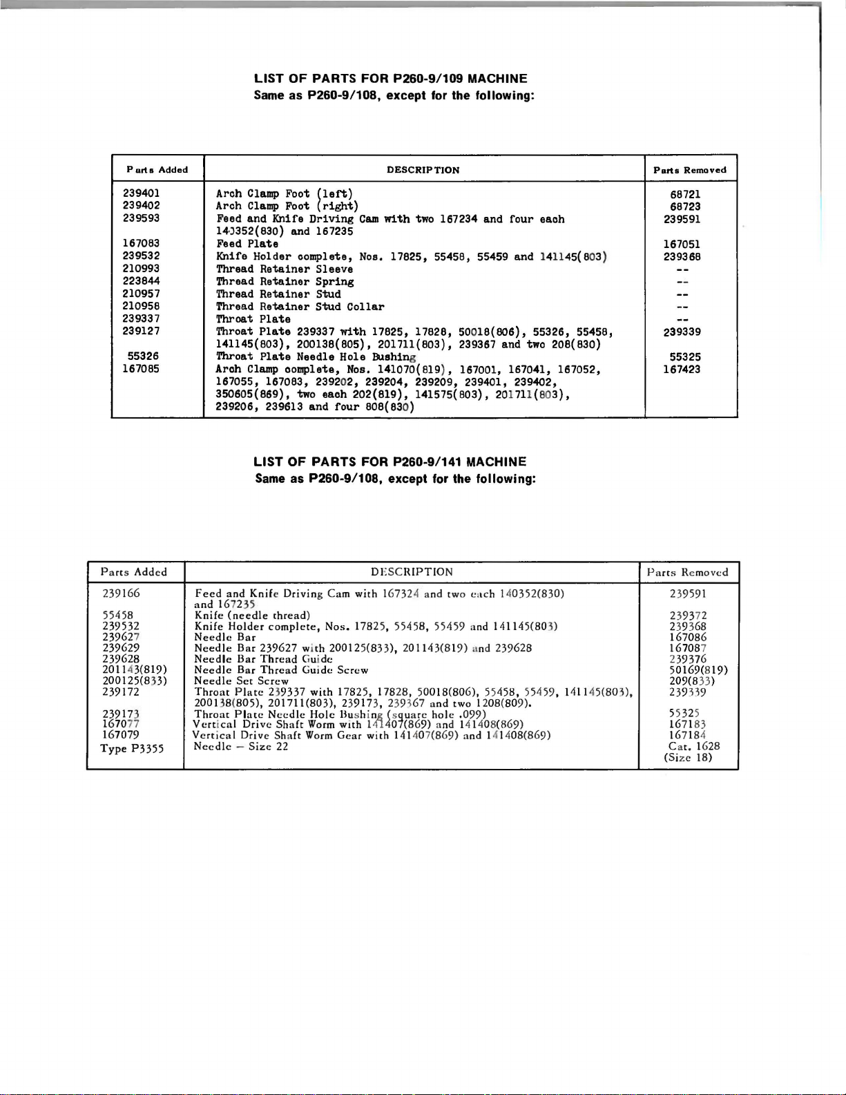
LIST
OF
PARTS FOR P260-9/109 MACHINE
Same
as P260-9/108, except
for
the
following:
Part a Added
239401
239402
239593
167083
239532
210993
223844
210957
210958
239337
239127
55326
167085
Arch Clamp Foot
Arch
Clamp
Feed and Knife
Foot
{left)
(right)
Driving
14)352{830) and 167235
Plate
Feed
Knife Holder
Thread
Thread
Thread
Thread
Throat
Throat
141145(803),
Throat
Aroh
Clamp
complete,
Retainer
Retainer
Retainer
Retainer
Sleeve
Spring
Stud
Stud
Plate
Plate
239337
with
200138(805), 201711{803), 239367 and two 208(830)
Plate
Needle Hole Bushing
complete,
167055, 167083, 23920
350605(869), two
239206, 239613 and
LIST
Same
eaoh
four
OF
PARTS FOR P260-9/141 MACHINE
as
P260-9/108, except
DESCRIPTION
Cam
with
two 167234 and
four
each
Nos. 17825, 55458, 55459 and 141145(803)
Collar
17825, 17828, 500
18(806),
55326, 55458,
Nos. 141070(819}, 167001, 167041, 167052,
2,
239204, 239209, 239401, 239402,
202(819),
141575(803), 201711(803),
808(830)
for
the
following:
Parts
68721
68723
239591
167051
239368
239339
55325
167423
Removed
P a rts Added
239166
55458
239532
23962 7
239629
239628
2011 43(819)
200125(8 33)
239172
23917 3
167077
167079
Type
P3355
Feed
and
and
167235
Knife
(needle
Knife
Holder
Needle
Needl
Needle
Needle
Needle
Throat Pla
2001 38(
Throat
Vertical
Vert
Needle
Bar
e Bar 239627 wi
Bar
Bar
Set
805),
Plate Needle
Drive
ic al Drive Shaft
- Si
D
ESC
Knif
e Driving Cam
thread
)
complete,
Thread
Thread
Screw
te
ze
Gui
Gui
239337
with
201711(803), 239173, 239% 7 a
Hole
Shaft
Worm
Worm
22
with
167324 a nd two
Nos.
17825, 5545
th
200125(833), 201143(8 1
de
de
Screw
17825, 17828, 50018 (806), 55458,
Bush
i'.fi~s7uare
with 1 0 (
Gear
with
RIPTIO
141407(869) and 141408(869)
N
ea
ch
8,
55459 a
hol
86
9) and 141408(869)
9)
nd
two 1208(80
e .099)
nd
and
140352(830)
141145(803)
239628
55459, 141145(80 3),
9)
.
Parts Re m
239591
239372
239368
167086
167087
239376
50169(819)
209(8
239339
55325
167183
167184
Cat. 1628
(Size 18)
oved
33
)
Page 33

'420.71
0
IN
u.s.A
PARTS
P260-9/108
MACHINE
FOR
3505n(819)
234n
141275
(869)t
t!
858/~
(830)
'::l
1065(830)
ITH SUPPLEMENTAL LISTS FOR MACHINES
P260-9/109. 126. 139 and
223711
239339
0
17825
~
5
2393n~
141
~
1c5(BOJl
141
~17828
8---201711(803)
"n
"I
"""
~~"~~~
~167064
'""'"""
r-··~·
~
i
""'
r------------------
-----i
l
239265
--------
239264
'
~5968t
~
[
;
:..~
"m'""'-~-
--------------,
2102----.
32sn
t560(803l
1
20
(S:
~
,.,
""
,
-l---239346
[
21
531
IT
239591t
Page 34

Page 35

239526
239525
167414t
239133
~
239322
\ '
462(830)'',_, •
167292
~
418(804)
"~~t.
200084
-~~50)
./
"~
228798
~
~
268121
~
2455
~
10141
....
1562(819)
~
-167048t
!84
~
I
228795
228796
I 4
1650(805)
232837
201135(803)
c
_::::::®91'1
~
131022
-LJ
167447t
239303
r-3-50-60-4-t
(869)
, .
.....___
2807
--®
1518
(805)
239341
!
167062t
!J
:
I
~
I
I
I I .. _ _ _ _
____
.J
I
I
I
I
I
I
I
1
I
-------.,.-
167181t
51948t
Page 36

Page 37

Union Special is offering two practical systems to help pinpoint and
reduce your sewing machine maintenance costs: a record keeping
system
to
and a parts inventory system to speed routine repairs.
Machine Maintenance Records
up
Union Special suggests two variations
record keeping system using cards provided by
(Form 237) for each sewing machine in a plant. When
required, the card is
and their cost are entered in the spaces provided and the card
on repair costs
Request Card" (Form 234), and a "Machine Repair Record"
233). When a machine requires service, the forelady or foreman fills
out the top of a "Repair Request Card" and gives it
fills in the time the repair work is started, the parts used and their cost,
help spot machines requiring abnormally high maintenance,
Repair-prone machines or inexperienced competent operators
your maintenance dollars in short order.
The first system utilizes a "Machine Maintenance Record" card
pulled from the file and the repair date, parts used,
The second system is
normally used when more detailed information
is
desired. Two record cards are used: a "Repair
To
help spot these problems ,
of
a simple maintenance
Union Special.
a repair is
to
a mechanic. He
is
refiled.
(Form
can
and the completion time. This data
"Machine Repair Record" kept in the office.
Whichever system is used, management now has
to reduce needless maintenance costs.
Repair
Part
While
eat
abnormally high maintenance,
caused by routine repairs.
recommends that manufacturers establish a formal parts inventory
system for each type of sewing machine they operate.
Excessive machine downtime and wasted hours by mechanics can
be
eliminated with an orderly in-plant inventory of the most commonly
needed parts. There is no longer a need to cannibalize other machines
for spare parts. Long waits for deliveries are avoided and machine
downtime
when the overall
Inventories
record keeping tells management which machines require
is
kept
to
a minimum. The cost of a parts inventory
sav
ings are considered.
MACHI
HI:
RC:PA&R
"CCQM)
CAitO
114lllt.
IIIAIII
..
~
-v·
1!211"
!:all"
~
rottt4\ 9a\t
=
- 1'\&C.
-
733-
nlne~e
~ec.otli
-·
For free sample copies
inventory lists for a variety
local Union Special Representative
is
then transferred to the permanent
an
invaluable tool
it
does little to help reduce the downtime
To
alleviate this situation, Union Special
-..
RUAI"
R•OucaT
~
..
rr~
lliW-j•mf
c.at
of
the machine record cards and spare part
of
the most popular machines, contact your
_______
I
-·-··
I
-
..
·--
-
.........
-·
..
-·-
..
oi
'
-
- rottt4\ t c.atli
.
~ ~r~\
........
,..,
.
t
...
I~IUD
..
c:ot,.~•oou
--------
or
write direct
CAHD -
-
------
..
AitT8UIID
-·- ·-·
23A- :
~e~"es
t
I
..
...
to
Union Special.
:.....
-
:=
I=
I=
I=
I=
I=
I=
r=
I=
is
small
Part
Number
G
52827-16
91 Presser
52805
22593
3026
90
52824
52828
87
121
52708
73
22563
33174
52842
28
• The parts and quantities listed above are intended to assist you in
sening
can only be established according to actual usage. The nature
sewing operation
D-16
A Differential feed dog 1
D-16
or
D-16
GBS
B Looper 2
B Looper needle guard holder screw 4
G Needle thread guide
B Needle thread guide
up
Description
Presser
Main feed dog 1
Throat plate (
Throat plate (
Needles (specify size)
Looper
Looper needle guard screw
the initial inventory
will
foot
foot
clamp
screw
Main feed
Differential feed dog screw 2
Throat plate screw 4
determine actual usage.
dog
screw
12
to
15
16
to
18. S.P .I.)
set
screw 2
wire
wire
of
spare parts. An efficient inventory
Minimum
Per 5 Machines
S.P.I.)
screw 4
Quantity
1
2
4
1
1
300
4
2
of
the
Part
Number
88
B
28
c
41076
73
22743
52945
77A
88
52844
90
52904
73
22564
21225
21227
29484
D Spreader thread
A
M Spreader
A Spreader thread guide 1
G Cast-off
A Cast-off
C-14
Description
Needle clamp
Needle clamp screw
Spreader thread
Spreader thread eyelet holder
Spreader set screws 4
Spreader holder screws 4
Spreader thread guide screws 4
Needle bar clamp screw 2
Looper gauge
Spreader gauge 1
Screw assortment 1
screw
eyelet
eyelet
wire
wire
screws 2
Minimum
Per 5 Machines
screw 4
screw
Quantity
4
2
2
4
2
2
1
Page 38

WORLD'S
FIIEIT
QUALITY
*
INDUSTRIAL
SEWING
MACHINES
UNION
facilities throughout the
aid
you
SPECIAL
maintains sales
world. These offices
in
the selection of the right sewing
equipment for your particular operation. Union
Special representatives
tory trained
promptly
tion,
there
and
and
efficiently. Whatever your loca-
is
a Union Special Representative
serve you. Check with
ATLANTA,
BOSTON, MASS.
CHICAGO,
DALLAS, TEXAS
LOS
ANGELES,
NEW
YORK, N.Y.
OPA
LOCKA,
PHILADELPHIA, PA.
GA.
ILL
CAL
FLA.
are
and
service men
able
to serve your needs
him
today.
MONTREAL,
TORONTO,
BRUSSELS, BELGIUM
LEICESTER,
LONDON, ENGLAND
PARIS,
STUTTGART,
and
service
are
CANADA
CANADA
ENG L
FRANCE
GERMANY
will
fac-
to
AND
Re
UNION
UNION
SPEC
SPEC
presentatives and di
Ind
ustrial
IAL
CO
RPORATIO N
400
IAL GmbH, SCHWABSTRASSE
stributors
cities
througho
N. FRANKLIN
33,
In
ut
the wor
D-7000
all
Important
ld.
ST.
, CHICAGO, IL 60610 U.S.A.
STUTTGART
1, W
EST
GERMANY
 Loading...