

Page 1

CATALOG NO.
Adjusting instructions and
N194-5
Flr•t E dltlon
STYLES
N150-1
N150-2
N150-5
illustrated parts list
CLASS N 1
Finest Quality
50
- B
lin
dstitch
m
achines
Page 2
CATALOG
NO.
Nl94-5
ADJUSTING
INSTRUCTIONS
AND
ILLUSTRATED
CLASS
STYLES
Nl50-l
Nl50-2
Nl50-5
First
Copyright
By
Union
Special Corporation
PART
Nl50
Edition
1986
LIST
Rights
Reserved
Printed in
July,
in
1986
2
All
Countries
U.S.A.
Page 3
IDENTIFICATION
OF
t4ACHINES
into
is
stamped
1
is
ted
back,
unless
Each
the
This
etc.,
otherwise noted.
Single
UNION
style
in
catalog
herein.
are
SPECIAL
plate
the
boss
All
taken from
Thread,
Needle Travels from
Line-of-Feed.
Adjustment
Stitch
Former.
Lengths.
Maximum
Nl50-l 1
light,
medium
materials.
1~150-2
skip
similar
stitch
garments.
Calibrated
of
the
Knee
Work
to
and heavy weight
Seam
specifications
Equipped with quick change
for
henuning
located
located
applies
references
Single
Left
Stitch
Lifter
Space
1
ratio
Seam
specifications
LEWIS
to
Penetration
machine
on
the
on
the
APPLICATIOI
specifically
to
direction,
the
operator's
DESCRIPTION
front
top
·J
carries
of
right
OF
CATALOG
to
the
position
OF
MACHINES
Curved Needle, Chain
Right and
Penetrates
Adjustment,
a
style
the
machine arm.
rear
of
standard
such as
while
Stitch,
Push
machine arm.
right
at
an
Button,
Length and a Large Easy-to-Read
for
to
Right
non-skip
103 EFl-1
medium
Inserting
of
Needle 7
stitch
materials,
weight
103 EFl-1
and
1/2
machine
and
or
103
selector
dresses,
Removing
inches (177.8mm).
for
also
EFm-1
felling
(modified).
dial
for
skirts,
or
103
EFm-1
number
styles
and 1
seated
Blind
Angle
Indicator
Work,
henuning
edge
non-skip
blouses,
(modified).
which
The
at
serial
of
machines
eft,
the
is
front
Stitch
90
degrees
for
Quick Easy
Marked
Oscillating
on
dresses
tape,
and
or
curtains
stamped
number
as
and
machine,
Machine.
to
with
Ridge
of
knit
2
to
1
and
weight
TO
PREVENT
- All
adjusting
-
Wear
- All
-DO
NOT
Nl50-5
trousers,
THIS
PERSONAL
power
sources
or
safety
shields
tamper with
Same
as
slacks
SAFETY
SYI~BOL
INJURY:
to
the
replacing
glasses.
and guards
safety
Style
and
machine
parts.
MUST
Nl50-l
similar
INDICATES
MUST
be
in
shields,
except
garments.
SAFETY RUl,.ES
CAUTION!
position
guards,
YOUR
be
TURNED
for
Seam
PERSONAL
before
etc.,
hemi
ng
cuffs
specification
SAFETY
OFF
before
operating
while machine
and
cuffl
103 EFl-1.
IS
INVOLVED
threading,
machine.
is
in
ess
medium
oiling,
operation.
3
Page 4
starts.
125
seconds
marked
The
machine
Use a good
at
in red.
should
be
grade of
100
degrees Fahrenheit.
However,
reference to the
oiled
straight
OILING
twice
daily,
before the
morning
and
mineral oil with a Saybolt viscosity of
Most
of
oiling
the
oiling
diagram will
points
be
OILING
on
the
machine
beneficial.
SPEED
afternoon
90
to
are
Maximum
direction
of the
Selection
material used.
good
stitch
sample
label.
as
far
needle
To
When
which
formation.
have
needle,
A complete order
changing the needle,
as
it
result.
recommended
handwheel
of
proper needle size
Thread
should pass freely through needle
speed for these machines
is
away
29
BM-075/029
29
BM-090/036
needle orders promptly
or
the type
will
may
go
have a hooked
and
would
tighten
number
read: 11100
or blunt point, as improper needle penetration will
from
the operator.
NEEDLES
NEEDLE
29
BL-065/025
29
BL-075/029
29
BL-090/036
29
BL-100/040
29
BL-11
is
determined
and
should
CHANGING
make
sure
clamp
is
3000
R.P.M., operating
TYPE
0/044
(ball point)
(ball point)
by
accurately
be
forwarded.
needles,
size
filled,
Type
eye
Use
29
BL-90/036
of thread
and
weight
in order to produce a
an
empty
the description
11
package, a
•
NEEDLES
that
it
is
inserted in the needle
carrier
screw securely. Immediately discard
of
on
any
4
Page 5
To
thread the machine, turn
carrier
is
in
its
highest position.
Refer to the threading diagram (Fig.l ).
Additional thread control
pull-off
eye 1 et
(A,
thread, as required.
Fig
.1
) to the
THREADING
handwheel
Fig. 1
can
be
obtained
right
for
ADJUSTING
in operating direction
by
repositioning needle thread
more
thread or to the 1
until
eft
the needle
for 1 ess
A
view
of
the foot
Below
is
labeling as
A-Needle
guide
ADJUSTING
of the presser foot (Fig.2)
which
the
shown
are referred to in
key
to
the
in Fig.2
PRESSER
FOOT
is
this
and
H
TO
NEEDLE
shown
to
illustrate
subsequent adjustments.
B-Cloth opening
C-Needle
D-Looper
E-Radius run-out
F-Cloth
G-Set
H-Needle
J-Cloth
K-Eccentric
track
opening
retainer
screw
groove
retainer
edge
bushing
Pin
L-Chaining finger
Insert a new
of proper type
far
as
it
will
and
the presser foot to the needle
(A,Fig.2)
when
needle
size
as Fig. 2
go
into the needle
traveling
from
carrier
so
left
and
securely tighten the
the needle point contacts the needle guide
to
right
and
so
that
contact with the needle guide until the point of the needle
the center of the cloth opening
needle continues to
the needle guide
move
until
to the
the needle reaches the needle track (C).
(~)
and
right,
the
right
side
of
play should develop
the various
clamp
screw. Set
the needle remains in
lies
in the
span
the cloth opening.
between
the needle
parts
between
As
the
and
5
Page 6

ADJUSTING
If
(A,Fig.3)
heads
on
retighten
foot
at a time,
(B)
top
do
the
side
up.
have been
screws
PRESSER
adjustment
on
top
not
contact
of
screws
Adjust
to
obtain
tightened,
(A)
should
of
each
(B)
the
FOOT
is
presser
the
bracket,
just
top
the
above
no
be
attempted.
TO
NEEDLE
required,
foot
brackets.
move
enough
screws
(A)
settings.
further
(Continued)
loosen
brackets,
Loosen screws
presser
to
hold
equally,
adjustment
so
that
foot
the
a 1 i
After
screws
the
(B)
up,
presser
ttl
screws
of
the
e
Fig. 3
manner. Turn
with
the
right
the
handwheel
side
Fig. 4
of
the
Turn
the
needle
should be
(D,Fig.2).
should be
this
have
in
cloth
is
operating
opening
the
handwheel
point
flush
to
not
to
rubber
screw
hole).
direction
extreme
cover
(A,
punch marks
viewed
stud
the
recheck
relation
Loosen
and
setting.
front
flush
wall
may
advance
desired
with
The
needle
the
the
case,
be
direction
(B,Fig.2)
plug ( A,Fi
in
and
Fig.5)
in
is
located
top.
the
needle
rotate
to
to
at
the
be
results.
SETTING
is
at
the 1 eft
point,
top
of
the
adjusted
unti 1 the
in
needle
Turn
until
right
turn
(Fig.5).
to
The
back
.003
necessary
the
the
end
the
So
that
in
Retighten
position
the
carrier
carrier
needle
so
inch
right
above
NEEDLE
in
operating
the
left
at
radius
travel
the
g.4).
crank
handwheel
the
needle
of
needle
its
the
ball
The
in
the
left
the
(.076
side
to
STROKE
direction
end
of
side
(accessible
of
side
as
carrier
side
adjustments
of
1 ooper opening
right
run-out
in
needle
presser
travel.
slot
needle
head,
the
the
clamp screw
required
of
slightly
end
of
the
the
Loosen
carrier
eccentric
is
stud
eccentric
at
clamp screw and
needle
of
looper
should be
of
the
mm)
presser
stroke.
of
edge
needle
following
eye
foot.
the
through
in
operating
is
Remove
ball
vertical
are
down,
the
rear
(C,Fig.3)
for
needle
from
foot.
retard
to
until
stroke,
(E).
will
is
flush
Remove
clamp
the
at
its
head
stud
and
as
ball
near
point
opening.
vertical
in
above
set
is
or
obtain
It
If
It
Fig. 5
CAUTION:
ball
against
that
flat
clearance
1 ooper
6
stud,
the
LOOPER
Insert
the
flat
in
carrier
carrier.
When
make
needle
between
adjusting
sure
shaft
TIMING
the
looper
on
its
and
looper
the
that
crank.
AND
ADJUSTMENT
into
shank
allow
1/64
shoulder
needle
it
its
corresponds
eccentric
is
carrier
inch
and end
seated
so
with
(.4mm)
of
Page 7
LOOPER
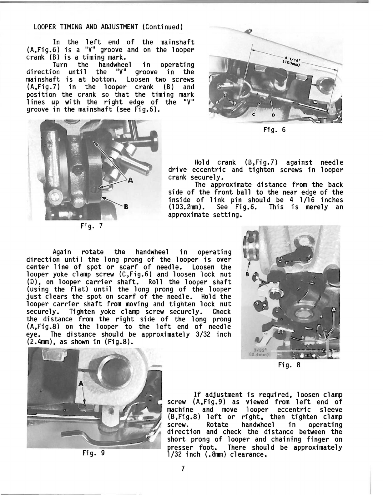
(A,Fig.6)
crank
direction
mai
(A,Fig.7)
position
lines
groove
(B)
Turn
nshaft
up
in
TIMING
the
In
is
a
is a timing
the
until
is
at
in
the
crank
with
the
mainshaft
AND
ADJUSTMENT
left
nyu
the
the
end
of
groove and
mark.
handwheel
the
bottom. Loosen
nyu
looper
so
that
right
(see
edge
(Continued)
the
mainshaft
on
the
in
operating
groove
two
crank
the
Fig.6).
(B) and
timing
of
looper
in
screws
the
the
mark
nyu
Fig. 6
Again
direction
center
looper
(D),
(using
just
looper
securely.
the
(A,Fig.8)
eye.
(2.4mm),
yoke clamp screw
on
clears
carrier
distance
The
Fig. 7
rotate
unti 1 the
line
the
of
spot
looper
on
distance
as
carrier
flat)
the
Tighten yoke clamp screw
shown
until
spot
shaft
from
the
in
the
1 ong prong
or
scarf
(C,Fig.6)
shaft.
the
on
scarf
from moving and
the
right
looper
should be
(Fig.8).
to
drive
crank
side
inside
(103.2nm). See
approximate
handwheel
of
the 1 ooper
of
needle.
and
Roll
long
of
side
the
approximately
prong
the
of
left
the
needle.
tighten
securely.
securely.
of
in
loosen
looper
of
the
1 ong prong
end
Hold
eccentric
The
of
operating
Loosen
the
of
3/32
crank
approximate
the
front
link
setting.
is
over
lock
shaft
looper
Hold
lock
Check
needle
inch
the
nut
the
nut
and
ball
pin
Fig.6.
(B,Fig.7)
tighten
distance
to
the
should
This
against
screws
near
be 4
in 1 ooper
from
edge
l/16
is
merely an
needle
the
of
inches
back
the
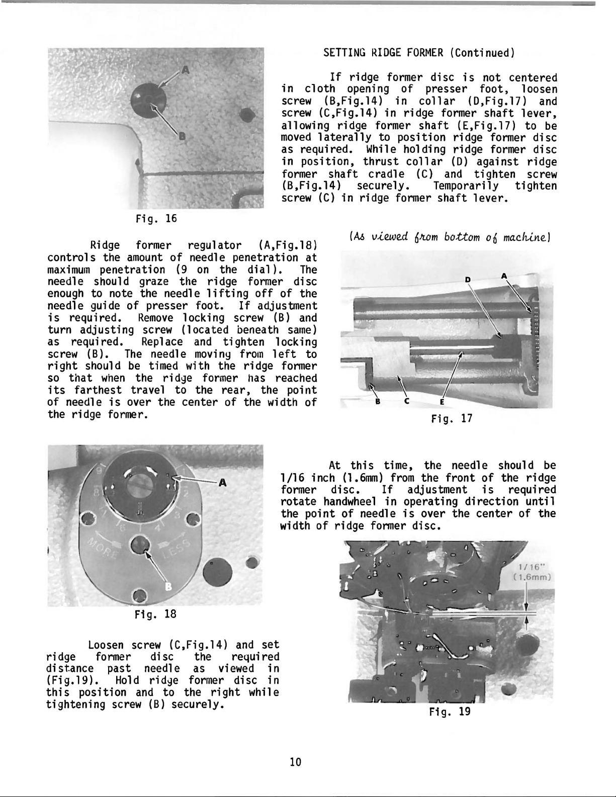
If
adjustment
Fig.
9
screw
machine and
(B,Fig.8)
screw.
direction
short
presser
1/32
(A,Fig.9)
prong
foot.
inch
(.8mm)
move
left
Rotate
and check
of
7
is
as
viewed from
1 ooper
or
right,
handwheel
the
looper
There
clearance.
and
should
Fig.
required,
eccentric
then
distance
chaining
be
8
loosen
left
tighten
in
between
approximately
clamp
end
sleeve
clamp
operating
finger
of
the
on
Page 8
LOOPER
TIMING
AND
ADJUSTMENT
(Continued)
Fig. 10
Fig.
11
---
and
not
Rotate
make
strike
handwheel
sure the short
looper opening in presser foot,
in operating
prong
of
(see Fig.lO).
If
adjustment
screw (A,Fig.9)
to
(B,Fig.8)
required,
tighten
operating
Fi
does
g.
needle
(see
If
until
clamp
direction
11
adjustment
the
this
screw. Rotate the
not
) •
screw (A,Fig.7)
as required
Rotate
until
handwheel
to ensure needle
distance
Fig.ll).
clamp
between
If
adjustment
screw (A,Fig.9)
is
required, loosen
and
strike
and
this
move
left
condition
and
check to ensure the
looper sleeve
the
LEAST
is
the crotch of looper
is
required, 1
turn crank
condition
in operating
enters
approximately equal
the prongs of looper (see
is
required, loosen
and
carefully
looper eccentric sleeve (B,Fig.8)
condition
move
eccentric sleeve 1
clamp
AND
ADJUSTMENT"
settings
driving crank
Different materials
may
require a
If
necessary, only
needle
and
nut
carrier
retighten nut
is
obtai ned, being careful not to
eft
or
screw securely.
has
NOTE:
been
a coordination
basicly involving looper
slightly
(D)
to
achieve desired conditions •••
and
and
slight
permitting
looper eccentric sleeve.
or
different
variation
roll
by
loosening screw (C,Fig.6)
the looper to the
rotation
screw.
right.
"LOOPER
direction
1 ooper does
clamp
AMOUNT
obtained
handwheel
oosen
(B)
slightly
is
obtained.
direction
rotate
until
this
Tighten
TIMING
carrier,
threads
of
used
settings.
of looper
and
in
set
of
SETTING
Pressure
regulated
by
nuts (A,Fig.l2). Turning
counterclockwise increases the tension
A
Fig.
12
turning
vi
e\~ed
screw
inside
uniformly
them
clockwise
in (Fig. 12). Set spring pressure
is
approximately 1 /16 inch
edge
8
of
when
nut.
knee
FEED
on
The
shaft
PLATES
the feed
acts
feed
the reverse, as
plates
is
depressed.
plates
(1
•
6mm)
must
is
them
and
so
from
drop
Page 9
If
and
move
clearance
adjustment
depressing
between .
1/3?"
(.Bmm)
feed
feed
is
required,
plates
SETTING
plate
and
FEED
loosen
shaft
depressing
PLATES
(B)
Fig.
set
so
screw
there
shaft.
13
(Continued)
(A,Fig.l3)
is
approximately
Tighten
set
•
•
in
front
screw
A
1/32
securely.
of
inch
cylinder
(.8mm)
If
adjustment
scre\'1 (B) which
release
by
Adjust
required
shaft
Tighten
pressure
turning
(B)
tension
turning
pivot
cradle
set
nut
is
flush
nut
bearing
to
remove
screw
on
(A,Fig.l6)
with
Fig.
14
locks
on
(A,Fig.l6)
(C,Fig.l7)
(B,Fig.l5)
cradle
screwdriver
is
required,
pivot
cradle
(C,Fig.l5)
shake,
spring
clockwise
selector
position,
as
former
the
shake
loosen
bearing
spring
counterclockwise.
(B,Fig.l7)
but
ridge
MUST
securely.
(A,Fig.l7)
slots
(C) and
(A,Fig.l7)
former
NOT
until
in
nut.
BIND.
Apply
screw
On
follows
disc
cloth
(left
set
as
by
SETTING
Style
(A,Fig.l4)
as
opening
or
Nl50-2,
shown
for
all
(A,Fig.l5)
right).
RIDGE
in
in
Fig.
machine
of
presser
FORMER
set
the
the
14.
must be
Fig.
15
skip
skip
Then
Styles.
centered
foot
stitch
stitch
proceed
Ridge
with
in
no
9
Page 10
in
cloth
screw (B,Fig.l4) in
screw (C,Fig.l4) in ridge former
allowing ridge former
moved
as required.
in
position,
former
(B,Fig.l4) securely. Temporarily
screw
Fig.
16
Ridge
controls the
maximum
penetration
former regulator (A,Fig.l8)
amount
of
needle penetration
(9
on
the
dial).
at
The
needle should graze the ridge former disc
enough
needle guide of presser foot.
is
turn adjusting
as required. Replace
screw (B).
right
so
its
of needle
to note the needle
required.
Remove
screw
The
needle
should
that
farthest
be
timed with the ridge former
when
the ridge former
travel
is
over the center of the width
lifting
off
If
adjustment
locking screw
(located beneath
and
tighten locking
movi
ny
from 1 eft
has
to
the
rear,
of the
(B)
and
same)
to
reached
the point
of
the ridge former.
SETTING
If
RIDGE
ridge former disc
opening
laterally
While
thrust
shaft
(C)
cradle
in ridge former
(A6
v-i..ewed
FORMER
of
collar
shaft
(Continued)
is
presser
(E,Fig.l7) to
not centered
foot,
loosen
(D,Fig.l7)
shaft
lever,
and
be
to position ridge former disc
holding ridge former disc
collar
(C)
(D)
and
against ridge
tighten screw
tighten
shaft
6Jtom
Fig.
lever.
bot:tom
17
o6
mac.IU.ne.J
Fig. 18
loosen
screw
(C,Fig.l4)
and
set
ridge former disc the required
distance past needle as
(Fig.l9).
this
position
tightening
Hold
and
screw
rid~e
to
the
(B)
securely.
viewed
in
former disc in
right
while
At
1/16 inch
former
rotate
handwheel
this
(1.6mm)
disc.
time, the needle should
If
in operating
the point of needle
width
of
ridge former
from
the
adjustment
is
over the
disc.
Fig.
front
direction
center
19
of
the ridge
is
required
be
until
of the
10
Page 11
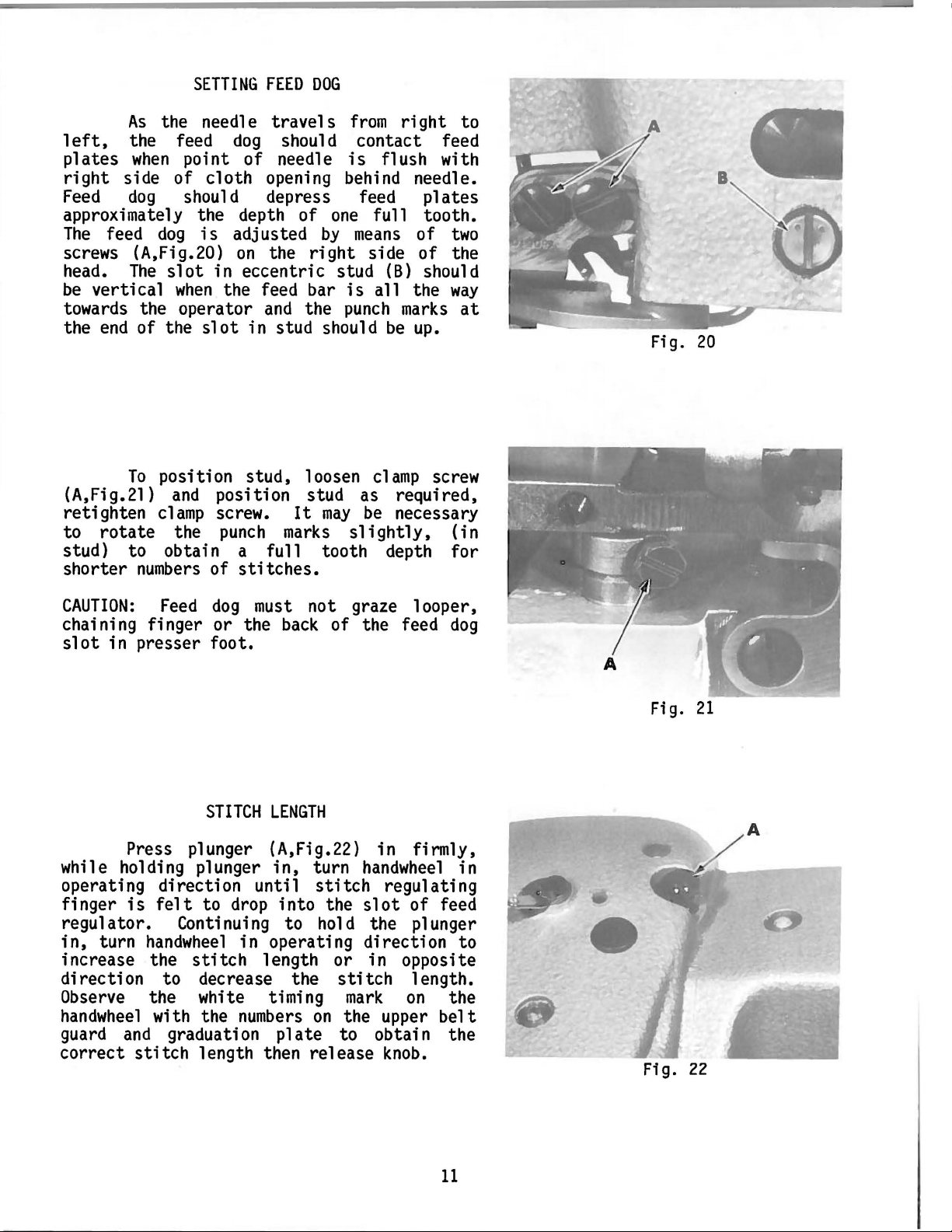
SETTING
As
the needle
left,
plates
right
Feed
the feed
when
point of needle
side of cloth opening behind needle.
dog
should depress feed
approximately the depth of
The
feed
dog
is
screws (A,Fig.20)
head.
be
The
vertical
slot
when
in eccentric stud
towards the operator
the
end
of the
To
(A,Fig.21)
retighten
to
rotate
slot
position stud, loosen
and
position stud as required,
clamp
the
screw.
punch
FEED
DOG
travels
dog
adjusted
should contact feed
by
on
the
right
the feed bar
and
the
in stud should
It
may
marks
from
is
flush with
one
full tooth.
means
side
(B)
is
all
punch
clamp
be
slightly,
right
plates
of
two
of
the
should
the
way
marks
be
up.
screw
necessary
(in
to
at
stud) to obtain a full tooth depth for
shorter
numbers
of
stitches.
Fig. 20
CAUTION:
chaining finger
slot
whi
in presser foot.
1 e
operating direction until
finger
Feed
dog
must
or
the
STITCH
not graze looper,
back
of the feed
LENGTH
Press plunger (A,Fig.22)
ho
1 ding p 1 unger
in,
turn
stitch
is
felt
to
drop
into the
in
firmly,
handwhee
regulating
slot
of feed
dog
1 in
regulator. Continuing to hold the plunger
in,
turn
increase the
direction
Observe
handwheel
guard
correct
handwheel
stitch
to
in
length or in opposite
decrease the
the white timing
with the
and
stitch
graduation
numbers
length then release
operating direction
on
plate
stitch
mark
the upper
to obtain the
length.
on
belt
knob.
to
the
Fig.
Fig.
21
A
22
11
Page 12
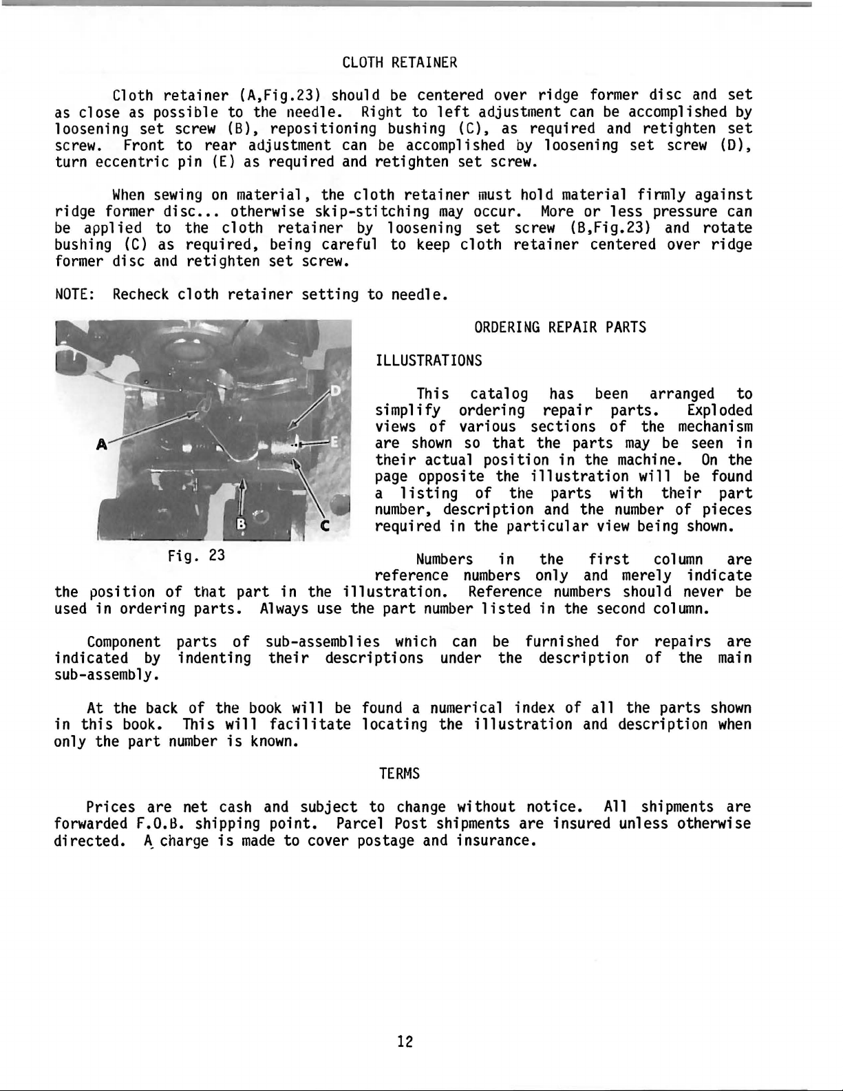
CLOTH
RETAINER
Cloth
as
close
loosening
retainer
as
possible to the needle. Right to
set
screw
(A,Fig.23) should
(B), repositioning bushing (C), as required
screw. Front to rear adjustment
turn eccentric pin
When
sewing
ridge former disc
be
applied to the cloth
bushing
former disc
NOTE:
(C)
as required, being careful to
and
Recheck
(E)
as required
on
material,
••• otherwise
retighten
cloth
retainer
skip-stitching
retainer
set
screw.
setting
the cloth
be
centered over ridge former disc
left
can
be
accomplished
and
retighten
retainer
may
by
loosening
keep
to needle.
ILLUSTRATIONS
This catalog has
simplify ordering
views
are
their
page
a
number,
of various sections of the
shown
actual position in the machine.
opposite the i
listing
description
required in the
adjustment
by
set
screw.
must
hold material firmly against
occur.
set
screw
cloth
retainer
ORDERING
can
loosening
More
or
(B,Fig.23)
centered over ridge
REPAIR
been
repair
so
that
the parts
11
us
tra
ti
of the parts with
and
the
particular
view
be
accomplished
and
retighten
set
screw
less
pressure can
and
PARTS
arranged to
parts.
may
be
on
wi
11
their
number
being
and
set
by
set
(D),
rotate
Exploded
mechanism
seen in
On
the
be
found
part
of pieces
shown.
Fig.
the position of
used
indicated
in ordering
Component
by
parts
23
that
part
parts.
of
indenting
in the
Always
illustration.
use the
sub-assemblies
their
descriptions under the description of the
reference
part
wnich
Numbers
numbers
Reference
number
can
in the
listed
be
first
only
and
numbers
in the second
column
are
merely indicate
should never
be
column.
furnished for repairs are
main
sub-assembly.
At
the
in
this
only the
back
book.
part
of the
This will
number
is
book
will
facilitate
known.
be
found
locating the
a numerical index of
illustration
all
the
and
description
parts
shown
when
TERMS
Prices are net cash
and
subject to
change
without notice.
All
shipments are
forwarded F.O.B. shipping point. Parcel Post shipments are insured unless otherwise
directed.
~charge
is
made
to cover postage
and
insurance.
12
Page 13

E X P L 0 D E D V I E W S
A N D
D E S C R I P T I 0 N 0 F P A R T S
13
Page 14

5
9~
n--w
12
13
~6
r:;r-
7
r:
14
15
35
~
33-£1
~
31
fl
~15
w---18
0-19
21
~~
30
14
Page 15

MISCELLANEOUS
COVERS
Ref.
Part
No. No.
1
2
3
4
5
6
7
8
9
10
11
12
13
14
15
16
17
18
19
20
21
22
23
24
25
26
27
28
29
30
31
32
33
34
35
36
37
38
39
40
Y80146
Y9526
Y6869
Y80295
Y80144
Y4475
Y93864
Y6147
Y559
Y80746
Y4555
Y80293
Y80118
Y960
Y4551
Y80297
Y3570
Y5347
Y81608
Y81607
Y3556
Y80154
Y80153
Y80155
Y5566
Y82305
Y80123
Y80122
Y3554
Y3642
Y80128
Y80127
Y80126
Y80125
Y5662
Y82304
Y4641
Y20072
Y80115
Y4481
Description
Finger
Screw
Screw
Head
Head
Screw
Plug
Screw
Spring
Top
Screw
Belt
Stitch
Stop
Screw
Belt
Screw
Screw
Stop
Stop
Screw
Felt
Oil
Oil
Screw
Work
Collar
Pin
Screw
Screw
Support Spring (small)
Support Spring (large)
Support Spring Pin
Support Latch
Screw
Work
Screw
Cloth Plate
Cylinder
Screw
Guard
---------------------------------------------
----------------------------------------------------
----------------------------------------------------
Cover
Cover
----------------------------------------------(rear)
----------------------------------------
----------------------------------------------------
-----------------------------------------------------
---------------------------------------------------Washer
Cover
--------------------------------------------
------------------------------------------------
----------------------------------------------------
Guard
Position
(upper)
Length
---------------------------------------
Indicator
Decal
--------------------------------------
Decal
----------------------------
----------------------------------------------------
Guard
(lower)
---------------------------------------
----------------------------------------------------
----------------------------------------------------
Pin
Pin
Cover
for
-------------------------------------------
Ridge
Forming
Shaft
-------------------------
----------------------------------------------------
Pad
-------------------------------------------------
Pan
Seal
---------------------------------------------
Pan
--------------------------------------------------
----------------------------------------------------
Support Bracket
-------------------------------------
---------------------------------------------------
------------------------------------------------------
----------------------------------------------------
----------------------------------------------------
-----------------------------------
-----------------------------------
---------------------------------------
Pin
----------------------------------------
----------------------------------------------------
Support Plate
---------------------------------------
----------------------------------------------------
Bumper
Cover
---------------------------------------
-------------------------------------------
----------------------------------------------------
Amt.
Reg.
1
1
1
1
1
2
1
1
1
1
1
1
1
1
3
1
2
1
1
1
1
1
3
1
2
1
1
1
2
2
1
1
1
1
1
1
1
1
1
1
15
Page 16

t-19
~15
,
~2
~3
~9
~
~10
tJ
11
r-13
@-14
17
~20
'•
..
··
..
~
1
(}--18
[}-18
~
&-
18-t]
~12
~15
..
17
~
..
®-17
I
..
-··
1
l_
d
30
~
16
Page 17

THREAD
EYELETS
AND
BUSHINGS
Ref.
No.
1
2
3
4
5
6
7
8
9
10
11
12
13
14
15
16
17
18
19
20
21
22
23
24
25
26
27
28
29
30
Part
No.
Y80740
Yl82
Y20126
Y85277
Y80744
Y80743
Y31111
Y6560
Y364
Y80745
Y80741
Y80742
Yl330
YA532
Y33764
Y80131
Y80132
Y4474
Y80136
Y4471
Y80393
Y80221
Y80511
Y80220
Y80204
Y3643
Y80200
Y80305
Y80135
Thread
Spring
Bushing
Spring
Spring
Spring Holder
Disc
Post
Nut
Eyelet
Support
Release
Screw
Washer
Eyelet
Oil
Wick
Oil
Cup
Oil
Tube
Screw
Oil
Tube
Screw
Eyelet
Needle
Bushing
Needle
Main
Shaft
Screw
Main
Knee
Oil
Shaft
Press
Tube
Description
Tension,
Complete
Nut
------------------------------------------
---------------------------------
---------------------------------------------
----------------------------------------------
----------------------------------------------
---------------------------------------
------------------------------------------------
------------------------------------------------
-------------------------------------------------
----------------------------------------------
--------------------------------------------Pin
-----------------------------------------
----------------------------------------------------
---------------------------------------------------
---------------------------------------------------
-------------------------------------------------
--------------------------------------------------
-------------------------------------------------
----------------------------------------------------
-------------------------------------------------
---------------------------------------------------(front)
Drive Shaft
------------------------------------------Bushing
-------------------------------
--------------------------------------------------
Drive Shaft
Bushing
Bushing
-------------------------------
---------------------------------------
---------------------------------------------------Bushing
Bushing
---------------------------------------
---------------------------------------
-------------------------------------------------
Amt.
~
1
1
1
1
1
1
2
1
1
1
1
1
1
1
2
4
4
6
1
1
1
1
1
2
1
1
1
1
1
2
17
Page 18

..
.·
.·
....
~
.•
4
(@)
~
2
7
141'
22
~
15
B
t12
, q
~
~
21
17
o--
18
19
~
~
·
II
9
10
~
""~
't
33
18
Page 19

NEEDLE
DRIVE
MECHANISM
Ref.
Part
No. No.
1
2
3
4
5
6
7
8
9
10
11
12
13
14
Y80701
Y3554
Y80202
Y80123
Y80145
Y3595
Y80208
Y5557
Y5553
Y80218
Y608
Y4554
Y80209
Y4391
15
16
17
18
19
20
21
22
23
24
25
26
27
28
29
30
31
Y80216
Y8021
Y3551
Y80211
Y4392
Y80217
Y80215
Y80391
Y80392
Y644
Y6035
Y4358
YA322
Y80224
Y4397
Y80226
32
33
34
35
36
37
Y3471
Y80328
Y5549
Y80222
Y80219
0
Description
Tension Release Eccentric
Screw
Mainshaft
Thrust Collar,
Handwheel
Screw
Needle
----------------------------------------------------
-----------------------------------------------for
Styles Nl50-l,
------------------------------------------------
---------------------------------------------------Driving Shaft Lever,
Screw
Screw
Crank
Fiber
Screw
Needle
-----------------------------------------------
-----------------------------------------------
----------------------------------------------Washer
----------------------------------------
----------------------------------------------Drive Eccentric,
Screw
Oil
Oil
------------------------------------------
Wick
---------------------------------------
Retainer (with hole)
Connecting
Screw
Needle
Screw
-----------------------------------------Drive Eccentric
------------------------------------------
Ball Eccentric
Oil
Retainer (without hole)
Needle
Eyelet
Spring
Screw
Screw
Nut
Pin
Screw
Needle
Needle
Screw
Needle
Screw
Collar
Needle
Thread
Pull-off
--------------------------------------------------Washer
--------------------------------------------
----------------------------------------------------
----------------------------------------------------
------------------------------------------------------
------------------------------------------------------
---------------------------------------------------Clamp
---------------------------------------------
---------------------------------------------------
---------------------------------------------------Carrier
-------------------------------------------
----------------------------------------------------
--------------------------------------------------Driving Shaft
--------------------------------
-5---------------------1
Complete
Complete
---------------------
--------------------
-----------------------
Rod
---------------------------------
-------------------------
---------------------------------
--------------------
-----------------------------------
-------------------------------------
Amt
~
1
4
1
1
2
1
1
1
1
1
1
1
2
3
2
1
1
1
2
1
1
1
1
1
1
2
1
1
1
1
1
2
1
1
1
1
19
Page 20

1
~
2
~
A-s
-
4
22
23
··-
8
··.
9
-
_.>
~~
...
··
··
.....
..
i
r(!~ro
<
18 17
w
-
~
;i9
·
ij-16
-
·-.
,
21
(;;/
--
~
20
_.·
..
_J
..
11
<i!D-12
1}--13
'·
···
..
·~
..
20
Page 21

KNEE
PRESS
PARTS
Ref.
No.
1
2
3
4
5
6
7
8
9
10
11
12
13
14
15
16
17
18
19
20
21
22
23
24
25
26
Part
No.
Y80325
Y80309
Y724
Y80308
Y4397
Y80304
Y80313
Y80311
Y80312
Y6047
Y80310
Y339
Y3394
Y5565
Y80306
Y3393
Y80314
Y4552
Y80303
Y3670
Y5555
Y80300
Y80299
Y80302
Y5662
Y80301
Description
Spring
Spring
Pin
Collar
Screw
Shaft
Shaft
Connecting
Lever
Screw
Lever
Nut
Stop
Screw
Spacer
Screw
Collar
Screw
Sleeve
Screw
Screw
Knee
Pin
-----------------------------------------------
------------------------------------------------------
---------------------------------------------------
----------------------------------------------------
----------------------------------------------------
---------------------------------------------------Link
------------------------------------------
----------------------------------------------------
----------------------------------------------------
----------------------------------------------------
-----------------------------------------------------Screw
-----------------------------------------------
----------------------------------------------------
---------------------------------------------------
----------------------------------------------------
---------------------------------------------------
----------------------------------------------------
---------------------------------------------------
----------------------------------------------------
----------------------------------------------------
Press,
Cushion
Rod
Screw
Pad
Complete
-------------------------------------
---------------------------------------------
-------------------------------------------------
-----------------------------------------------
-------------------------------------------------
Amt.
~
1
1
1
1
1
1
1
1
1
2
1
1
1
1
1
1
1
1
1
2
2
1
1
1
1
1
21
Page 22

3
v-4
5
p..
14
u-w
I
12~
3 • . .
~
.
~
) 9
--w
'
10~""
!:'
~·
'· ' .
I::'
-
~
19
20
-
~~
31
&-21
~
30
~'\9
38
"""
-
37
22
~"
37
38
39
Page 23

PRESSER
FOOT
AND
FEED
PLATES
Ref.
Part
No. No.
1
2
3
4
5
6
7
8
9
10
11
12
13
14
15
16
17
18
19
20
21
22
23
24
25
26
27
28
29
30
31
32
33
34
35
36
37
38
39
Y4317
Y4398
Y80381
Y7420
Y80290
Y4246
Y80291
Y80418
Y4395
Y80357
Y4393
Y80358
Y81352
Y4245
Y80355
Y4283
Y81354
Y3393
Y80354
Y80356
Y3312
Y4642
Y80398
Y338
Y80346
Y6339
Y80395
Y6051
Y80399
Y6051
Y80396
Y6339
Y80321
Y339
Y80316
Y4481
Y80348
Y6638
Y239
Screw
Screw
----------------------------------------------------
----------------------------------------------------
Presser Foot Bracket
Adjusting
Screw
Presser Foot
Screw
Presser Foot
-----------------------------------------------
------------------------------------------
Assembly,
---------------------------------------Chaining Finger
Screw
Retainer
Screw
Needle
Retainer
Screw
Spring
Screw
Edge
Screw
----------------------------------------------Stop
-----------------------------------------------
Guide
----------------------------------------
--------------------------------------------
-----------------------------------------------
----------------------------------------------
-----------------------------------------------
Guide
------------------------------------------
-----------------------------------------------
Eccentric Pin
Bushing
Screw
Screw
Feed
----------------------------------------------------
Plate,
Nut
Feed
Screw
Feed
Screw
Feed
Plate,
Screw
Feed
Screw
Feed
Nut
Holder
Screw
Feed
Screw
---------------------------------------------------
----------------------------------------------------
Plate Holder Spring
----------------------------------------------------
Adjusting
---------------------------------------------
-----------------------------------------------
Complete,
------------------------------------------------Plate Holder
-----------------------------------------------
Plate
------------------------------------------
----------------------------------------------Complete,
-----------------------------------------------
Plate
------------------------------------------
-----------------------------------------------
Plate Holder
-------------------------------------------------
Nut
--------------------------------------------
Description
------------------------------------Complete
for Style Nl50-l
---------
-------------------------------------
---------------------------------------
---------------------------------------
(right)
----------------------------
-----------------------------------
(left)
-----------------------------
-----------------------------------
---------------------------------
Amt.
~
2
2
2
2
1
1
1
1
1
1
1
1
1
1
1
1
1
1
1
1
1
1
1
1
1
1
1
1
1
1
1
1
1
1
1
1
2
2
2
23
Page 24

8
ef-9
~10
.11
s-Q
~
18
!P~
19
r
20
fto-23
~qq;
22
21
24
o
~w
~u
!1-17
24
Page 25

RIDGE
FORMING
DRIVING
PARTS
Ref.
No.
1
2
3
4
5
6
7
8
9
10
11
12
13
14
15
16
17
18
19
20
21
22
23
24
25
26
27
28
29
30
31
32
33
Part
No.
Y80325
Y80309
Y6048
Y80659
Y3556
Y80658
Y80651
Y3555
Y3559
Y81601
Y80619
Y81602
YA1196
Y81617
Y80656
Y5061
Y80005
Y80652
Y6031
Y3554
Y80655
Y8047
Y80606
Y80657
Y3558
Y80605
Y80665
Y80661
Y3473
Y80664
Y80663
Y80662
Spring
Spring
Screw
Connecting
Screw
Collar
Ridge
Screw
Screw
Ridge
Oil
Oil
Eccentric
Screw,
Connecting
Pin
-----------------------------------------------
---------------------------------------------------
---------------------------------------------------Link
------------------------------------------
----------------------------------------------------
---------------------------------------------------
Former
Bracket
----------------------------------------------------
----------------------------------------------------
Former
Cap
Wick
Eccentric, for Styles Nl50-l,
--------------------------------------------------
------------------------------------------------Washer,
for Styles Nl50-l,
Rod,
for Styles Nl50-l,
Oscillating Shaft
Screw
Gear
Roller
Screw
Screw
Gear
Screw
Lever
Eccentric
Screw
Connecting
Spring
Latch
Screw
Spring
Locking
Collar
----------------------------------------------------
(large)
---------------------------------------------
---------------------------------------------------
----------------------------------------------------
----------------------------------------------------
(small)---------------------------------------------
----------------------------------------------------
----------------------------------------------------
------------------------------------------------
---------------------------------------------------Pin
-------------------------------------------
Pin
-----------------------------------------------
Pin
------------------------------------------------
----------------------------------------------------
--------------------------------------------------Latch
--------------------------------------------
---------------------------------------------------
Description
-------------------------------------
-5------------1
for Styles Nl50-l,
-5------------------1
-5-----------------------------2
-5--------------------1
----------------------------------------
Amt.
~
1
1
1
1
2
1
1
3
1
1
1
1
3
1
1
1
2
1
1
1
1
2
1
1
1
1
1
1
1
25
Page 26

..
····
...
-··
a---q
I
I
9---..@>
I
_j
16
17
~
~····
·'
..
-..
'
~21
..
. •
•'
···
..
··.
··
..
··
..
··· ...
20
,(d)~~
41
40
r
39
~
~
38
..
&-19
9;
. .
..
,· · . .
/·'
~
~
25
24
·-.
__
..
··
...
-··
.-··
26
Page 27

STITCH
DEPTH
REGULATING
PARTS
Ref.
Part
No. No.
1
2
3
4
5
6
7
8
9
10
11
12
13
14
15
16
17
18
19
20
21
22
23
24
25
26
27
28
29
30
31
32
33
34
35
36
37
38
39
40
41
Y82108
Y5328
Y6520
Y80690
Y80673
Y6222
Y80693
Y5431
Y675
Y80694
Y3553
Y6900
Y80692
YA7616
Y6855
Y3559
Y6892
Y80612
Y3393
Y80615
Y338
Y6639
Y80614
Y255
Y6651
Y355
Y8061
Y5047
Y80613
Y3561
Y553
Y6242
Y80609
Y80618
Y4390
YA347
Y80611
Y80616
Y81609
Y571
Y371
0
Description
Ridge
Screw
Screw
Ridge
Screw
Washer
Regulator
Locking
Screw
Regulator Flange
Screw
Adjusting
Screw
Pivot
Ridge
Screw
Collar
Nut
Screw
Cradle
Nut
Screw
Nut
Ridge
Screw
Pivot Bearing
Screw
Washer
Connecting
Ball
Connecting
Screw
Nut
Ridge
Flange
Ridge
Washer
Nut
Former
Graduation Plate
----------------------------
----------------------------------------------------
---------------------------------------------------Former
Handle
Screw
Regulator
Regulator
Assembly
--------------------------
----------------------------------------------
-----------------------------------------------
-------------------------------------------
----------------------------------------------------
--------------------------------------------------Gear
-------------------------------------------
Screw
--------------------------------------------
----------------------------------------------------
-----------------------------------------
---------------------------------------------------Screw
------------------------------------------
----------------------------------------------------
Screw
Former
---------------------------------------------Shaft Cradle
--------------------------------
----------------------------------------------------
---------------------------------------------------
------------------------------------------------------
---------------------------------------------------Spring
--------------------------------------------
------------------------------------------------------
----------------------------------------------------
-----------------------------------------------------Former
Shaft
Lever
---------------------------------
----------------------------------------------------
--------------------------------------------
----------------------------------------------------
--------------------------------------------------Pin
-------------------------------------------
Stud
-----------------------------------------------Link
------------------------------------------
----------------------------------------------------
-----------------------------------------------------Former
Shaft
---------------------------------------
---------------------------------------------------
Former
Disc, for Style Nl50-l
----------------------
---------------------------------------------------
------------------------------------------------------
Amt.
~
1
3
1
1
1
2
1
2
2
1
1
1
1
2
1
1
1
1
1
1
1
1
1
1
1
1
1
1
1
1
1
1
1
1
2
1
1
1
1
1
1
27
Page 28

··.
4
··.
22~~
20
.
0
21~
16v-
~
·
..
'-
6 - 19
18
161
23
28
Page 29

LOOPER
DRIVING
PARTS
Ref.
No.
1
2
3
4
5
6
7
8
9
10
11
12
13
14
15
16
17
18
19
20
21
22
23
24
Part
No.
Y80403
YA120
Y80215
Y80400
Y80401
Y3560
Y80402
Y80404
Y4280
Y80405
Y3471
Y80406
Y4399
Y354
Y80415
Y4312
Y4554
Y80408
Y3392
Y80411
Y5558
Y80412
Y80407
Y80413
Crank
Oil
Oil
Looper
Bearing
Screw
Yoke
Screw
Looper
Screw
Locking
Ball
Screw
Screw
Ball
Screw
Eccentric Sleeve
Screw
Eccentric
Looper
Looper
Pin
------------------------------------------------
Wick
-------------------------------------------------
Retainer (without hole)
Driving Crank,
Driving
Screw
Crank
Crank
----------------------------------------------Bushing
Block
--------------------------------------------
----------------------------------------------------
Pin
-------------------------------------------------
---------------------------------------------------Yoke
----------------------------------------------
----------------------------------------------------
Nut
----------------------------------------------
Joint
-----------------------------------------------
----------------------------------------------------
----------------------------------------------------
-----------------------------------------------------
----------------------------------------------------
-----------------------------------------
----------------------------------------------------
Pin
--------------------------------------------
Carrier
-------------------------------------------
---------------------------------------------------
Description
------------------------------
Complete
---------------------------
---------------------------------------
---------------------------------------
Amt.
~
1
1
1
1
1
2
1
1
1
1
1
1
1
1
1
3
1
1
1
1
1
1
1
1
29
Page 30

3
._.A
-u
, It\
/-
.
,
e-1s
_._
.,
11
30
'<
······
rf9
17
16
Page 31

FEED
DRIVING
PARTS
Ref.
No.
1
2
3
4
5
6
7
8
9
10
11
12
13
14
15
16
17
18
19
20
21
22
23
24
25
26
Part
No.
Y80520
Y80521
Y80523
Y80524
Y80522
Y3391
Y80215
Y80001
Y80502
Y80501
Y4250
YA80503
Y80504
Y3557
Y80294
Y3555
Y80508
Y4471
Y552
Y8051
0
Y5547
Y80507
Y80506
Y3474
Y80296
Feed
Screw
Oil
Oil
Feed
Regulating Pushbutton,
Pushbutton
Spring
Sleeve
Shaft
------------------------------------------
----------------------------------------------
----------------------------------------------
-----------------------------------------------
----------------------------------------------------
Wick
-------------------------------------------------
Retainer (without hole)
Regulator,
Complete
Regulating Eccentric
Regulator
Screw
Ball
-----------------------------------------------------
Ball Spring
Screw
---------------------------------------------------Counterweight
Screw
Eccentric
Screw
Washer
Feed
Screw
link
link
Screw
Feed
---------------------------------------------------Pin
----------------------------------------------------
---------------------------------------------------
Dog
-------------------------------------------------
----------------------------------------------------
Pin
-------------------------------------------------
-----------------------------------------------------
----------------------------------------------------
lever
-------------------------------------------
-----------------------------------------------
----------------------------------------------
--------------------------------------------
--------------------------------------------
-----------------------------------------------
Description
Complete
---------------------
------------------------------
---------------------------------
--------------------------------
Amt.
Req.
1
1
1
1
1
1
2
2
1
1
1
3
1
1
1
1
1
1
2
2
1
1
1
1
1
1
31
Page 32

1
(
~
~
u
._
5
23
((@~·
/
./
:. 4
t!)
/
~
IZ:i:d
~~
:
11
~··
9
12
.
flJ
14
;1
--
35
·
~
·
~7
36
~
/
38
~~40
41
32
Page 33

SKIP
STITCH
PARTS
PECULIAR
TO
STYLE
Nl50-2
ONLY
Ref.
No
1
2
3
4
5
6
7
8
9
10
11
12
13
14
15
16
17
18
19
20
21
22
23
24
25
26
27
28
29
30
31
32
33
34
35
36
37
38
39
40
41
42
Part
No.
Y80601
Y80602
Y80624
Y80603
Y80681
Y80623
Y80646
Y4281
Y80645
Y8047
Y80647
Y80636
Y3641
Y80635
Y3393
Y80640
Y4475
Y721
Y80644
YA80503
Y80675
Y80643
Y81345
Y80291
Y80418
Y4246
Y80357
Y4395
Y80358
Y4393
Y80352
Y4245
Y80353
Y4241
Y80355
Y80360
Y4283
Y3393
Y80354
Y3312
Y80356
Y80627
Ridge
Former
Eccentric
Skipstitch Eccentric
Eccentric Pin
Connecting
Oil
Wick
Gear
Support
Gear
Screw
Gear
Screw
(large)
----------------------------------------------------
(small)---------------------------------------------
---------------------------------------------------Reduction
Eccentric
Screw
Collar
Screw
----------------------------------------------------
---------------------------------------------------
----------------------------------------------------
--------------------------------------------
Rod
-------------------------------------------
-------------------------------------------------
---------------------------------------------
---------------------------------------------
Gear
Bushing
-------------------------------------------
----------------------------------------
Skipstitch Selector
Screw
Indicator
Bushing
Ball
Spring
Shaft
Presser Foot
----------------------------------------------------
Pin
--------------------------------------------
--------------------------------------------------
-----------------------------------------------------
---------------------------------------------------
----------------------------------------------------
Assembly,
Presser Foot
Finger
Screw
----------------------------------------------
-----------------------------------------------
Retainer
Screw
Needle
Screw
----------------------------------------------Guide
-----------------------------------------------
Retainer
Screw
Guide
Screw
Spring
Edge
Screw
Screw
-----------------------------------------------
-----------------------------------------------
-----------------------------------------------
----------------------------------------------
Guide
-----------------------------------------------
-----------------------------------------------
----------------------------------------
Stop
---------------------------------------
----------------------------------------
--------------------------------------------
------------------------------------------
Eccentric Stud
Ridge
Screw
Bushing
Former
-----------------------------------------------
--------------------------------------------Disc
----------------------------------------
Description
-----------------------------------
-------------------------------------
--------------------------------------
Complete
--------------------------
--------------------------------------
Amt.
~
1
1
1
1
1
1
1
2
1
2
1
1
1
1
2
1
1
1
1
1
1
1
1
1
1
1
1
1
1
1
1
1
1
1
1
1
1
1
1
1
1
1
33
Page 34

22
27
24
28
,25
34
Page 35

PRESSER
FOOT,
RIDGE
FORMER,
EDGE
GUIDE
FOR
STYLE
Nl50-5
ONLY
Ref.
No.
1
2
3
4
5
6
7
8
9
10
11
12
13
14
15
16
17
18
19
20
21
Part
No.
Y81364
Y80291
Y80418
Y4246
Y80357
Y4395
Y80358
Y4393
Y81366
Y4245
Y80355
Y81354
Y4283
Y80356
Y3393
Y80354
Y3312
Y81901
Y554
YA9853
Y81629
Presser Foot
Presser
Chaining Finger
Screw
Retainer
Screw
Needle
Screw
Retainer
Screw
Spring
Edge
Guide
Screw
Bushing
Screw
Eccentric
Screw
Edge
Guide
Washer
Screw
Ridge
---------------------------------------------------
---------------------------------------------------Former
Description
Assembly,
Foot
Complete
--------------------------
----------------------------------------
-------------------------------------
----------------------------------------------Stop
---------------------------------------
-----------------------------------------------
Guide
----------------------------------------
-----------------------------------------------
--------------------------------------------
-----------------------------------------------
----------------------------------------------
------------------------------------------
-----------------------------------------------
---------------------------------------------
-----------------------------------------------
Stud
--------------------------------------
-----------------------------------------------
-----------------------------------------------
Disc
----------------------------------------
Amt.
Reg.
1
1
1
1
1
1
1
1
1
1
1
1
1
1
1
1
1
1
2
2
1
Ref.
No.
22
23
24
25
26
27
28
29
Part
No.
Y80910
Y80162
Y80163
Y5148
Y5147
Y80161
Y5161
Y362
ACCESSORIES
Description
Thread
Bolt
Nut
Stand,
Thread
Pin,
Screw
Screw
Thread
Hanger
Spool
Complete
------------------------------------------
-----------------------------------
---------------------------------------
-----------------------------------------------
----------------------------------------------Stand
----------------------------------------
-----------------------------------------------------
------------------------------------------------------
Amt.
Reg.
1
1
1
2
1
1
3
3
35
Page 36

NUMERICAL
INDEX
OF
PARTS
Part
No.
¥182
Y239
¥338
¥339
Y354
Y355
¥364
Y371
Y441
Y552
Y553
Y554
Y559
Y571
Y608
Y644
Y675
Y721
Y724
Y960
¥1330
¥3312
¥3391
¥3392
¥3393
¥3394
¥3471
¥3473
¥3474
¥3551
¥3553
¥3554
¥3555
¥3556
¥3557
¥3558
¥3559
¥3560
¥3561
Y3570
¥3595
¥3641
¥3642
¥3643
¥3670
¥4241
¥4245
¥4246
¥4250
•••••••••••••••
..••.••.•••••••
•••••••••••••••
•••••••••••••••
•••••••••••••••
••••.•••.••••..
•••••••••••••••
•••••••••••••••
•••••••••••••••
•••••••••••••••
••••.••.••.•...
•••••••••••••••
•••••••••••••••
•••••••••••••••
•••••••••••••••
•••••••••••••••
•••••••••••••••
•••••••••••••••
•••••••••••••••
•••••••••••••••
••••••••••••••
••••••••••••••
••••••••••••••
••••••••••••••
••••••••••••••
••••••••••••••
••••••••••••••
••••••••••••••
••••••••••••••
••••••••••••••
••••••••••••••
••••••••••••••
••••••••••••••
••••••••••••••
••••••••••••••
••••••••••••••
••••••••••••••
••••••••••••••
••••••••••••••
••••••••••••••
••••••••••••••
••••••••••••••
••••••••••••••
••••••••••••••
••••••••••••••
••••••••••••••
••••••••••••••
••••••••••••••
••••••••••••••
Page
No.
17
23
23,27
21
,23
29
27
17
27
31
31
27
35
15
27
19
19
27
33
21
15
17
23,33,35
31
29
21,23,27,
33,35
21
19,29
25
31
19
27
15,19,25
25,31
15,25
31
25
25,27
29
27
15
19
33
15
17
21
33
23,33,35
23,33,35
31
Part
No.
Y4280
¥4281
¥4283
¥4312
¥4317
¥4358
¥4390
¥4391
¥4392
¥4393
¥4395
¥4397
¥4398
¥4399
¥4471
¥4474
¥4475
¥4481
¥4551
¥4552
¥4554
¥4555
¥4641
¥4642
¥5061
¥5328
¥5347
¥5431
Y5547
¥5549
¥5553
¥5555
¥5557
¥5558
¥5565
¥5566
¥5662
¥6031
¥6035
¥6047
¥6048
¥6051
¥6147
¥6222
¥6242
¥6339
¥6520
¥6560
¥6638
¥6639
••••..•.••••.•
••••••••••••••
••••••••••••••
••••••••••••••
••••••••••••••
••••••••••••••
••••••••••••••
••••••••••••••
••••••••••••••
••••••••••••••
••••••••••••••
••••••••••••••
••••••••••••••
••••••••••••••
••••••••••••••
••••••••••••••
••••••••••••••
••••••••••••••
••••••••••••••
••••••••••••••
••••••••••••••
••••••••••••••
••••••••••••••
••••••••••••••
••••••••••••••
••••••••••••••
••••••••••••••
••••••••••••••
••••••••••••••
••••••••••••••
••••••••••••••
••••••••••••••
••••••••••••••
••••••••••••••
••••••••••••••
••••••••••••••
••••••••••••••
••••••••••••••
••••••••••••••
••••••••••••••
••••••••••••••
••••••••••••••
••••••••••••••
••••••••••••••
••••••••••••••
••••••••••••••
••••••••••••••
••••••••••••••
••••••••••••••
••••••••••••••
~~
No.
29
33
23,33,35
29
23
19
27
19
19
23,33,35
23,33,35
19,21
23
29
17
17
15,33
15,23
15
21
19,29
15
15
23
25
27
15
27
31
19
19
21
19
29
21
15
15,21
25
19
21
25
23
15
27
27
23
27
17
23
27
Part
No.
¥6651
¥6855
¥6869
¥6892
¥6900
¥7420
¥8047
¥9526
¥20072
¥20126
¥31111
¥33764
¥80001
¥80005
¥80115
¥80118
¥80122
¥80123
¥80125
¥80126
¥80127
¥80128
¥80131
¥80132
¥80135
¥80136
¥80144
¥80145
¥80146
¥80153
¥80154
¥80155
¥80200
¥80202
¥80204
¥80208
¥80209
¥80210
¥80211
¥80215
¥80216
¥80217
¥80218
¥80219
¥80220
¥80221
¥80222
¥80224
¥80226
¥80290
••••••••••••••
••••••••••••••
••••••••••••••
••••••••••••••
••••••••••••••
••••••••••••••
••••••••••••••
••••••••••••••
•••••••••••••
•••••••••••••
•••••••••••••
•••••••••••••
•••••••••••••
•••••••••••••
•••••••••••••
•••••••••••••
•••••••••••••
•••••••••••••
•••••••••••••
•••••••••••••
•••••••••••••
•••••••••••••
•••••••••••••
•••••••••••••
•••••••••••••
•••••••••••••
•••••••••••••
•••••••••••••
•••••••••••••
•••••••••••••
•••••••••••••
•••••••••••••
•••••••••••••
•••••••••••••
•••••••••••••
•••••••••••••
•••••••••••••
•••••••••••••
•••••••••••••
•••••••••••••
•••••••••••••
•••••••••••••
•••••••••••••
•••••••••••••
•••••••••••••
•••••••••••••
•••••••••••••
•••••••••••••
•••••••••••••
•••••••••••••
Page
No.
27
27
15
27
27
23
25,33
15
15
17
17
17
31
25
15
15
15
15,19
15
15
15
15
17
17
17
17
15
19
15
15
15
15
17
19
17
19
19
19
19
19,29,31
19
19
19
19
17
17
19
19
19
23
36
Page 37

NUMERICAL
INDEX
OF
PARTS
Part
No.
Y80291
Y80293
Y80294
Y80295
Y80296
Y80297
Y80299
Y80300
Y80301
Y80302
Y80303
Y80304
Y80305
Y80306
Y80308
Y80309
Y80310
Y80311
Y80312
Y80313
Y80314
Y80316
Y80321
Y80325
Y80328
Y80346
Y80348
Y80352
Y80353
Y80354
Y80355
Y80356
Y80357
Y80358
Y80360
Y80381
Y80391
Y80392
Y80393
Y80395
Y80396
Y80398
Y80399
Y80400
Y80401
Y80402
Y80403
Y80405
Y80406
Y80407
•••••••••••••
•••••••••••••
•••••••••••••
•••••••••••••
•••••••••••••
•••••••••••••
•••••••••••••
•••••••••••••
•••••••••••••
•••••••••••••
•••••••••••••
•••••••••••••
•••••••••••••
•••••••••••••
•••••••••••••
•••••••••••••
•••••••••••••
•••••••••••••
•••••••••••••
•••••••••••••
•••••••••••••
•••••••••••••
•••••••••••••
•••••••••••••
•••••••••••••
•••••••••••••
•••••••••••••
•••••••••••••
•••••••••••••
•••••••••••••
•••••••••••••
•••••••••••••
•••••••••••••
•••••••••••••
•••••••••••••
•••••••••••••
•••••••••••••
•••••••••••••
•••••••••••••
•••••••••••••
•••••••••••••
•••••••••••••
•••••••••••••
•••••••••••••
•••••••••••••
•••••••••••••
•••••••••••••
•••••••••••••
•••••••••••••
•••••••••••••
Page
No.
23,33,35
15
31
15
31
15
21
21
21
21
21
21
17
21
21
21,25
21
21
21
21
21
23
23
21,25
19
23
23
33
33
23,33,35
23,33,35
23,33,35
23,33,35
23,33,35
33
23
19
19
17
23
23
23
23
29
29
29
29
29
29
29
Part
No.
Y80408
Y80411
Y80412
Y80413
Y80415
Y80418
Y80501
Y80502
Y80504
Y80506
Y80507
Y80508
Y80510
Y80511
Y80520
Y80521
Y80522
Y80523
Y80524
Y80601
Y80602
Y80603
Y80605
Y80606
Y80609
Y80611
Y80612
Y80613
Y80614
Y80615
Y80616
Y80618
Y80619
Y80623
Y80624
Y80627
Y80635
Y80636
Y80640
Y80643
Y80644
Y80645
Y80646
Y80647
Y80651
Y80652
Y80655
Y80656
Y80658
Y80659
•••••••••••••
•••••••••••••
•••••••••••••
•••••••••••••
•••••••••••••
•••••••••••••
•••••••••••••
•••••••••••••
•••••••••••••
•••••••••••••
•••••••••••••
•••••••••••••
•••••••••••••
•••••••••••••
•••••••••••••
•••••••••••••
•••••••••••••
•••••••••••••
•••••••••••••
•••••••••••••
•••••••••••••
•••••••••••••
•••••••••••••
•••••••••••••
•••••••••••••
•••••••••••
•••••••••••••
•••••••••••••
•••••••••••••
•••••••••••••
•••••••••••••
•••••••••••••
•••••••••••••
•••••••••••••
•••••••••••••
•••••••••••••
•••••••••••••
•••••••••••••
•••••••••••••
•••••••••••••
•••••••••••••
•••••••••••••
•••••••••••••
•••••••••••••
•••••••••••••
•••••••••••••
•••••••••••••
•••••••••••••
•••••••••••••
•••••••••••••
Page
No.
29
29
29
29
29
23,33,35
31
31
31
31
31
31
31
17
31
31
31
31
31
33
33
33
25
25
27
~.27
27
27
27
27
27
27
25
33
33
33
33
33
33
33
33
33
33
33
25
25
25
25
25
25
Part
No.
Y80661
Y80662
Y80663
Y80664
Y80665
Y80673
Y80675
Y80681
Y80690
Y80692
Y80693
Y80694
Y80701
Y80740
Y80741
Y80742
Y80743
Y80744
Y80745
Y80746
Y81345
Y81352
Y81354
Y81364
Y81366
Y81601
Y81602
Y81607
Y81608
Y81609
Y81617
Y81629
Y81901
Y82108
Y82304
Y82305
Y85277
Y93864
YA120
YA322
YA347
YA532
YA1196
YA7616
YA9853
YA80503
••••••••••••••
••••••••••••••
••••••••••••••
••••••••••••••
•••••••••••••
•••••••••••••
•••••••••••••
•••••••••••••
•••••••••••••
•••••••••••••
•••••••••••••
•••••••••••••
•••••••••••••
•••••••••••••
•••••••••••••
•••••••••••••
•••••••••••••
•••••••••••••
•••••••••••••
•••••••••••••
•••••••••••••
•••••••••••••
•••••••••••••
•••••••••••••
•••••••••••••
•••••••••••••
•••••••••••••
•••••••••••••
•••••••••••••
•••••••••••••
•••••••••••••
•••••••••••••
•••••••••••••
•••••••••••••
•••••••••••••
•••••••••••••
•••••••••••••
•••••••••••••
•••••••••••••
•••••••••••••
•••••••••••••
•••••••••••••
•••••••••••••
•••••••••••••
•••••••••••••
••••••••••••
Page
No.
25
25
25
25
25
27
33
33
27
27
27
27
19
17
17
17
17
17
17
15
33
23
23,35
35
35
25
25
15
15
27
25
35
35
27
15
15
17
15
29
19
27
17
25
27
35
31,33
37
Page 38

MACHINE
INVENTORY
INFORMATION
Unit
Number
Maker's
Name
Machine
Style
Serial
Number
Needle
Type
Date
Purchase
Of
·-
ADDITIONAL
INFORMATION:--
-
----
----
---
-----
----
Page 39

Notes:
__
__
____
______
____
__
______________
__
_
Page 40

WORLDWIDE SALES
AND
SERVICE
Union
service
offices
sewing
Union
servicemen
serve
Whatever
Corporation
with
It is
COLUMBIA®
Special
facilities
will
aid
equipment
Special
are
your
your
representative
him
today.
important
Corporation
throughout
you
In
for
Corporation
factory
needs
promptly
location,
to
remember
machines
maintains
the
the
selection
your
particular
representatives
trained
there
Is a Union Special
to
serve
that
are
also
products
Special Corporation, thus offering
most
complete
line
of
the
Finest Quality
machines.
Fmest
Ouahty
Union
Uni
on
Special
Special
Corporation
, GmbH,
. 400 N.
Schwab
strasse 33 0 ·7000
world.
and
and
LEWIS®
the
Franklin
sales
and
These
of
the
right
operation.
and
are
able
efficiently.
you.
Check
and
of
Union
Industry
sewing
Street
Stuttg
Gainesville, GA
Norcross, GA
Chicago,
Dallas,
El
Paso,
Commerce, CA
to
the
. Ch icago. IL 60610 ,
art 1 West
Philadelphia,
Opa-Locka, FL
Montreal, Quebec
Toronto,
Brussels, Belgium
Leicester, England
Paris, France
Stuttgart,
Hong Kong
Osaka, Japan
Other Representatives throughout
all parts of the world
Germ
IL
TX
TX
Ontario
W. Germany
US
A
any
PA
Pnnted
in U.S.A.
 Loading...