

Page 1
INSTRUCTIONS AND ILLUSTRATED PARTS MANUAL
03/05/09
MATTRESS TAPE EDGE MACHINE
MANUAL NO. PT0603-GR
MT111T01-1
Page 2

MANUAL NO. PT0603-GR INSTRUCTIONS and ILLUSTRATED PARTS MANUAL for
MT111 SERIES MACHINES
First Edition Copyright 2007
by
Union Special Machine Company
Rights Reserved in All Countries
PREFACE
This manual has been prepared to simplify ordering spare parts.
Views of various sections of the mechanism are shown so that the parts may be seen in their actual position
in the sewing machine. On the page opposite the illustration will be found a listing of parts with their part
numbers, descriptions and the number of pieces required in the particular view being shown.
Numbers in the first column are reference numbers only, and merely indicate the position of that part in the
illustrations. Reference numbers should never be used in ordering parts. Always use the part number listed in
the second column.
Component parts of subassemblies which can be furnished for repairs are indicated by indenting their
description of the main subassembly.
This manual has been comprised on the basis of available information. Changes in design
and / or improvements may incorporate a slight modification of configuration in illustrations or cautions.
On the following pages will be found illustrations and terminology used in describing the parts for your machine.
IMPORTANT: ON ALL ORDERS, PLEASE INCLUDE PART NUMBER, PART NAME AND STYLE OF
MACHINE FOR WHICH PART IS ORDERED.
2
Page 3

CONTENTS
PREFACE.................................................................................................................................................. 2
SAFETY RULES .......................................................................................................................................... 4
CAUTION AREAS ..................................................................................................................................... 5
IDENTIFICATION OF MACHINES ............................................................................................................. 6
STYLES OF MACHINES ............................................................................................................................. 6
NEEDLES................................................................................................................................................... 6
NEEDLE ORDERING................................................................................................................................. 6
TORQUE REQUIREMENTS ........................................................................................................................ 6
THREADING THE MACHINE .................................................................................................................... 7
INSERTING NEEDLE ................................................................................................................................. 8
STITCH FORMATION ................................................................................................................................ 8
TROUBLE SHOOTING .............................................................................................................................. 8
ADJUSTING THE STITCH LENGTH ............................................................................................................ 9
LUBRICATION ........................................................................................................................................ 10
OIL SPECIFICATION REQUIREMENTS .................................................................................................... 10
OIL FLOW DIAGRAM ............................................................................................................................ 12
NEEDLE / LOOPER SYNCHRONIZATION .............................................................................................. 14
UPPER ROLLER DRIVE PLATE ASSEMBLY .............................................................................................. 15
LOWER ROLLER SETTING....................................................................................................................... 16
UPPER ROLLER AND PRESSER FOOT SETTING ...................................................................................... 16
PRESSER FOOT PRESSURE ..................................................................................................................... 16
NEEDLE BAR SETTING ............................................................................................................................ 17
LOOPER SETTING................................................................................................................................... 17
NEEDLE GUARD SETTING ...................................................................................................................... 18
NEEDLE THREAD CONTROL.................................................................................................................. 18
LOOPER THREAD CONTROL ................................................................................................................ 19
BUSHINGS .............................................................................................................................................. 21
NEEDLE BAR DRIVE ............................................................................................................................... 23
UPPER MAIN SHAFT ............................................................................................................................... 25
CRANKSHAFT ASSEMBLY ...................................................................................................................... 27
LOOPER DRIVE AND NEEDLE GUARD DRIVE ...................................................................................... 29
DRIVE PARTS AND THROAT PLATE SUPPORTS ..................................................................................... 31
PRESSER FOOT LIFT ................................................................................................................................ 33
OIL PUMP............................................................................................................................................... 35
OIL TUBES ............................................................................................................................................... 37
OIL DISTRIBUTOR ASSEMBLY ................................................................................................................. 39
NEEDLE THREAD CONTROL.................................................................................................................. 41
LOOPER THREAD CONTROL ................................................................................................................ 43
FRONT AND LOOPER COVERS ............................................................................................................ 45
COVERS................................................................................................................................................. 47
BACK AND RIGHT COVERS .................................................................................................................. 49
SEWING PARTS ...................................................................................................................................... 51
ACCESSORIES ....................................................................................................................................... 53
NUMERICAL INDEX OF PARTS .............................................................................................................. 60
NUMERICAL INDEX OF PARTS .............................................................................................................. 61
3
Page 4
SAFETY RULES
1. Before putting the machine described in this manual into service, carefully read the instructions. The starting of
each machine is only permitted after taking notice of the instructions and by qualified operators.
2. Observe the national safety rules valid for your country.
3. The sewing machine described in this instruction manual is prohibited from being put into service until it has been
ascertained that the sewing units which these sewing machines will be built into, have conformed with the provisions of EC Machinery Directive 98/37/EC, Annex II B.
The machine is only allowed to be used as foreseen. The foreseen use of the particular machine is described in
paragraph STYLE OF MACHINE of this instruction manual. Another use, going beyond the description, is not as
foreseen.
4. All safety devices must be in position when the machine is ready for work or in operation. Operation of the
machine without the appertaining safety devices is prohibited.
5. Wear safety glasses.
6. In case of machine conversions and all valid safety rules must be considered. Conversions and changes are
made at your own risk.
7. The warning hints in the instructions are marked with oneof these two symbols.
8. When doing the following the machine has to be disconnected from the power supply by turning off the main switch
or by pulling out the main plug:
8.1 When threading needle(s), looper, spreader, etc.
8.2 When replacing any parts such as needle(s), presser foot, throat plate, looper, spreader,
feed dog, needle guard, folder, fabric guide, etc.
8.3 When leaving the workplace and when the work place is unattended.
8.4 When maintaining the machine which has to be done regularly (see also LUBRICATION).
8.5 When using clutch motors without actuation lock, wait until motor is totally stopped.
9. Maintenance, repair and conversion work (see item 8) must be done only by trained technicians or special skilled
personnel under condsideration of the instructions. Only genuine spare parts approved by Union Special have to be
used for repairs.
10. Any work on the electrical equipment must be done by an electrician or under direction and supervision of special
skilled personnel.
11. Work on parts and equipment under electrical power is not permitted. Permissible exceptions are described in the
applicable section of standard sheet EN 50110 / VDE 0105.
4
Page 5
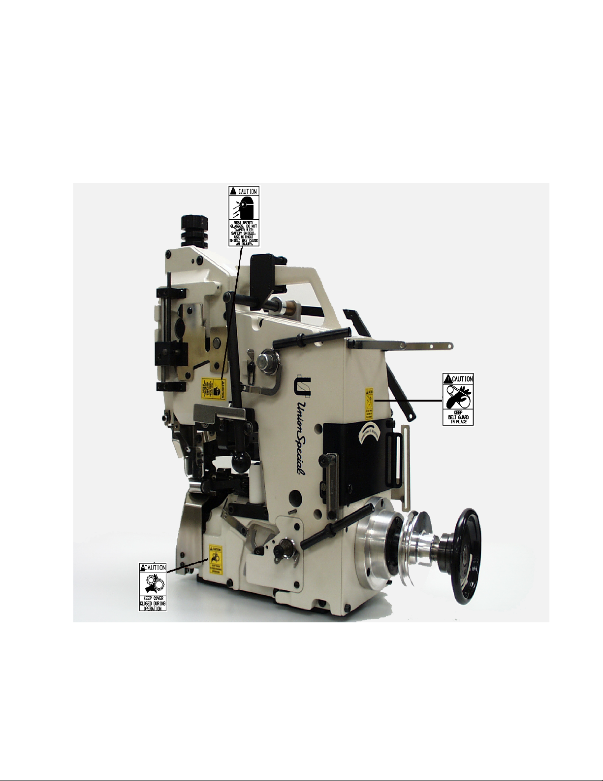
CAUTION AREAS
5
Page 6

IDENTIFICATION OF MACHINES
Each UNION SPECIAL MT111 series machine is identified by a style number, which is stamped on the style plate located
on the center portion at the rear of the casting. Serial number is also stamped.
STYLES OF MACHINES
High speed and high performance sewing machine for sewing tape edge binding on mattresses.
One needle, high throw, internal forced lubrication, with automobile type filter, totally enclosed looper mechanism,
independently driven rear needle guard with no readjustment required when changing stitch length, and upper and lower
driven feed rollers.
MT111T01-1: Sewing machine for sewing the mattress tape edge with a two thread double locked stitch.
Seam Specification: 401 BSa-1 (ASTM Std. D 6193)
Stitch Range: 4 to 9 SPI (6.3 – 12.5mm)
Standard Setting: 6 SPI (4.2mm)
Capacity beneath
Upper Roller: 5/8 inch (15.9mm)
Maximum Speed: up to 3100 stitches/minute
Weight Net: 41 kg
ASTM = American Society for Testing Materials
NEEDLES
Each needle has both a type and a size number. The type number denotes the kind of shank, point, length, groove,
finish and other details. The size number, stamped on the needle shank, denotes the largest diameter of the blade
measured midway between the shank and the eye. Collectively, the type and size number represent the complete
symbol which is given on the label of all needles packed and sold by Union Special.
TYPE AND DESCRIPTION
794HSERV4—Round shank with flat, round point, single groove spotted, chromium plated. Size available: 180/073.
When changing the needle, make sure it is fully inserted in the needle head with the flat of the needle shank facing the screw,
before the screw is tightened.
NEEDLE ORDERING
When ordering needles use the complete type and size numbers as printed on the package to ensure prompt and
accurate processing of your order. A complete order should read as follows:
100 needles, type 794HSERV4, size 180/073
TORQUE REQUIREMENTS
Torque (measured in inch-pounds) is a "rotating" force in pounds applied through a distance by a lever (in inches or
feet). This is accomplished by a wrench, screwdriver, etc. Many of these devices are available, which when set at
the proper amount of torque will tighten the part to the correct amount and no tighter.
All straps and eccentric should be tightened to 26-28 inch pounds (3 - 3.2 Nm) unless otherwise noted.
Screws requiring a specific torque will be indicated on the illustrations.
6
Page 7
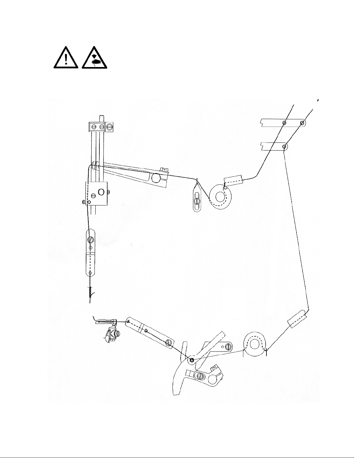
THREADING THE MACHINE
Turn off main power switch before threading! When using clutch motors
without actuation lock wait until motor has completely stopped.
7
Page 8
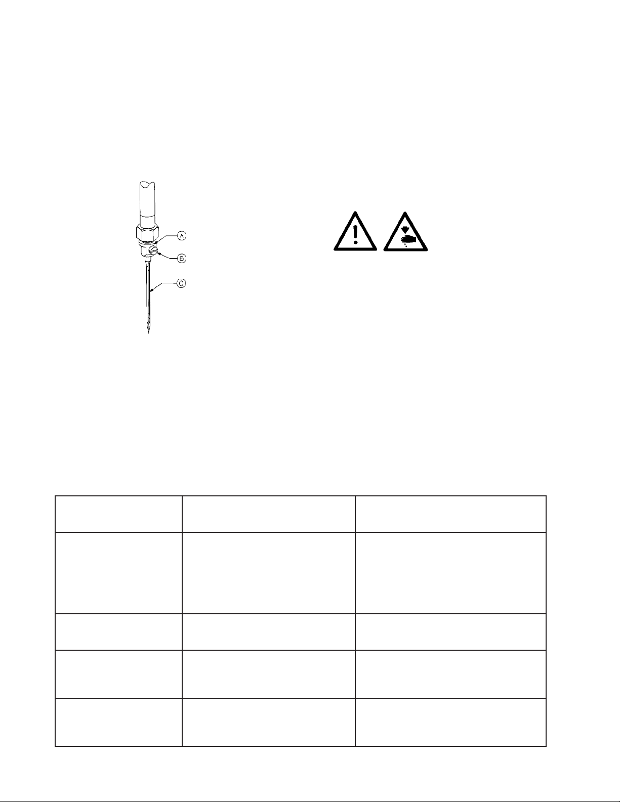
INSERTING NEEDLE
The standard needle is 794HSERV4-180/073. Insert needle according to the following procedure:
1. Bring needle head (A) to the highest position.
2. Loosen screw (B) Insert needle (C) into hole. The needle spot should face rearwards as viewed from the operator’s
side, with the tapered flat of the needle shank facing screw (B).
3. Retighten screw (B).
Turn off main switch on machine before replacing the needle!
STITCH FORMATION
1. Set the needle thread tension to pull the thread loop up near the bottom of the material with a consistent size for a uniform
stitch.
2. Set the looper thread tension just tight enough to control the thread and prevent skipped stitches.
3. Set the needle thread strike-off so the support shaft extends a minimum of .500" (12.7mm) above its guide block.
TROUBLE SHOOTING
MELBORPESUACNOITULOS
dnaenocdaerhtneewtebgnidaerhT
enihcamgniwes
sdaerhtnekorB
gniweselihw
sehctitsdemroflaM
syarfdaerhteldeeN
mottobno
maesnwesfo
tnulbpitrepooL
tnulbpiteldeeN
noisnetdaerhtnitondaerhT
steleyetcerrocroylbmessa
egdeprahssahrepooL
noitropreniaterta
eldeenecalpeR
margaidgnidaerhtwolloF
ylthgilsegdeprahsffuB
repoolecalperro,rrubffoenotS
ecnerefretniynamorfsdaerhtetarapeS
eguagerusserpliO
noitcnuftonseod
noitarepognirud
delliferasretlifeniL
lairetamngierofhtiw
sretlifenilni-tliubecalpeR
8
Page 9
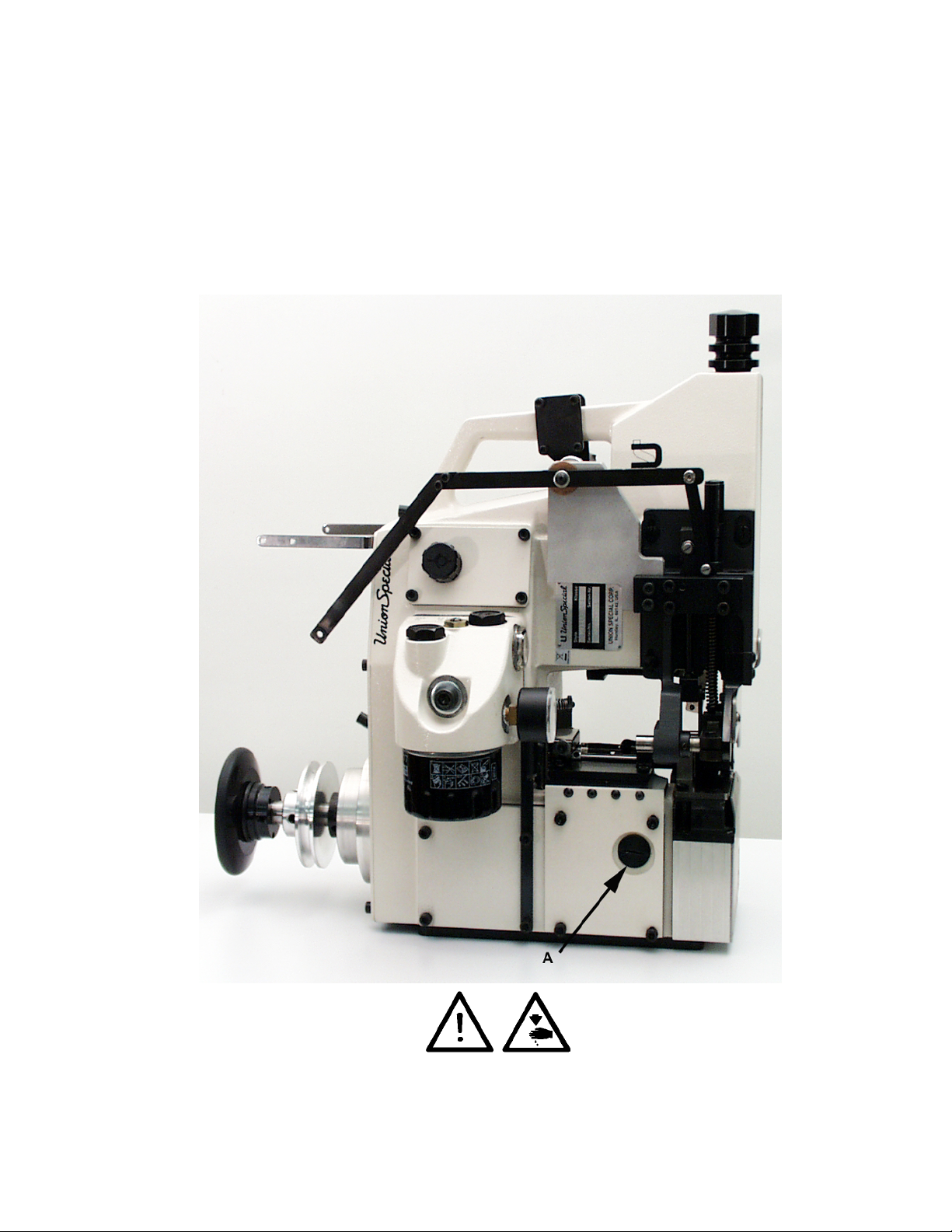
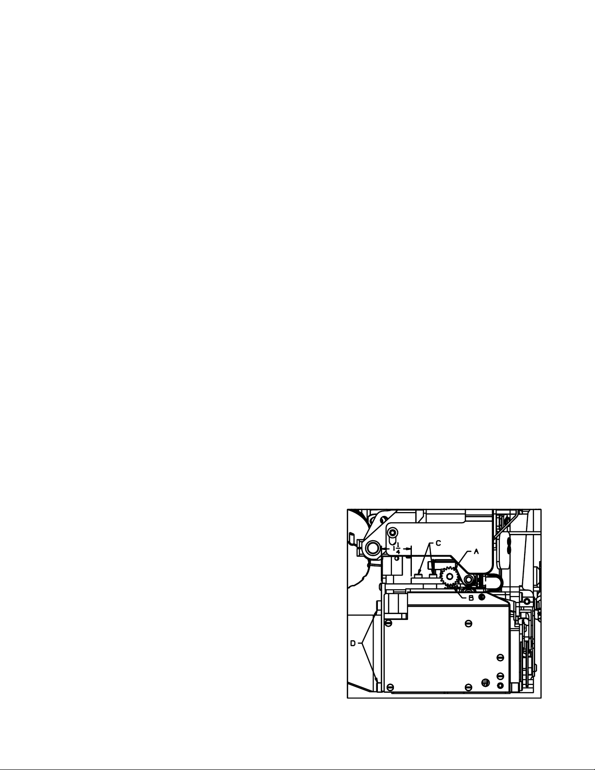
ADJUSTING THE STITCH LENGTH
1. Remove plug (A).
2. Turn handwheel until center adjustment screw is located.
3. Turn adjustment screw clockwise to lengthen stitch length.
4. Turn adjustment screw counterclockwise to shorten stitch length.
5. Replace plug (A) after adjustment is made.
NOTE: Needle guard requires no readjustment when stitch length is changed.
Turn off main power before setting stitch length!
When using clutch motors without actuation lock wait until the motor has completely stopped.
9
Page 10

LUBRICATION
CAUTION! Oil has been drained from machine before shipping and the reservoir must be filled before beginning to operate.
Use the oil with UNION SPECIAL Specification No. 175 which is delivered with the accessories of the machine. This oil is
equivalent to a hydraulic oil according to ISO VG 22 and can be purchased from UNION SPECIAL in 0.5 liter containers
under part No. 28604R, or in 5 liter containers under part No. 28604V.
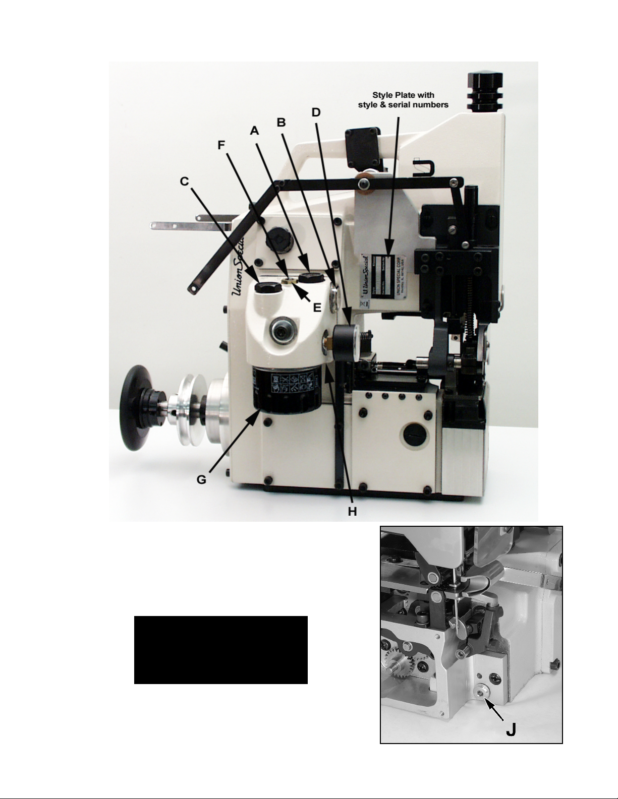
ADDING OIL THE FIRST TIME, AND WHEN OIL AND FILTER ARE CHANGED:
1. Remove 26mm oil fill screw (A) nearest oil level indicator (B) and 26mm oil filter fill screw (C) above oil filter. Fill oil
in filter, and then lock screw (C).
2. Add oil in the oil hole until oil registers in the oil level indicator (B).
3. Run machine and add oil until oil line is at the center dot of the oil level indicator (B).
The oil capacity of the machine with the filter is 0.5 liters (18.0 ounces).
4. Screw oil fill screw (A) back on and tighten.
5. The oil pressure gauge (D) should register 15 PSI (1 bar) while the machine is running.
6. The oil pressure and oil level should remain as above while the machine is in operation.
7. If the oil pressure registers more than 15 PSI (1 bar) loosen nut (E) and turn screw (F) counterclockwise to reduce the
oil pressure.
8. Retighten nut (E).
NOTE: If the machine has not been used in a while, the oil level will take about 30 seconds of machine running
time to raise to the center level, and the oil pressure to register at the normal pressure.
Follow this same
procedure after changing oil and filter.
NOTE: If during operation no oil pressure is indicated on the oil pressure gauge (D), shut off the machine and
CHANGING THE OIL AND FILTER:
1. Oil and oil filter (G) should be replaced after the first 200 hours of operation. Thereafter oil and filters must be
2. Use Union Special Spec. 175 or equivalent.
3. There are two 5mm Allen head oil drain plug screws used to drain the oil from the machine. Plug screw (H),
4. Loosen screw (J) first and oil fill screw (A) to drain the oil from the head.
5. Loosen screw (H) next and drain the oil from the pump and filter.
6. Replace and tighten both screws (J) and (H) and retighten oil fill screw (A)
7. Remove oil filter and replace with new one.
OIL SPECIFICATION REQUIREMENTS
All oils shall be non-compounded, straight mineral oils, of high viscosity index (will not thin down excessively with heat).
Practically all oil companies have Union Special Specification 175 and their industrial representatives will make their
recommendations conforming to Union Special requirements.
check the oil lines to make sure they are not bent improperly to reduce oil flow or if there is an obstruction
in the oil line or oil siphon filters.
changed every 500 hours of operation.
located on the underside of the reservoir next to the filter, is used to drain the oil from the oil pump and filter and
screw (J), located just below the looper and needle guard shaft is used to drain the oil from the machine head.
UNION SPECIAL SPEC. 175
Nominal Viscosity 100 S.S.U at 100°F (Nominally ISO Grade 22).
Viscosity at 100°F 90 - 125 S.U.S (22 cSt)
Flash Point (min.) 350°F (176°C)
Pour Point (max.) 20°F (- 7°C)
Color (max). 1
Neutralization No. (max). 0.10
Viscosity Index (D&D min.) 90
Copper Corrosion (max.) 1A
Aniline Point 175 - 225°F (79 - 107°C)
Compounding Not a requirement
10
NOTE: The use of non-corrosive
oxidation, rust and foam
inhibitators and / or film strength
and lubricity enhancers is
permitted, but these additives
must be completely soluble in the
oil, they must not separate, nor be
removed by wick feeding.
Corrosive “EP” (extreme
pressure), tackiness / adhesive,
lead soap and detergent
additives are not permitted, nor
are solid lubricants like
graphite, PTFE, etc.
Page 11
NOTE:
DO NOT run the machine
after the oil is drained!
11
Page 12
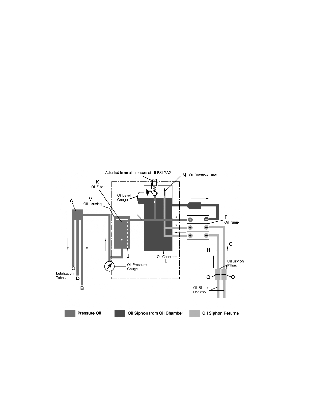
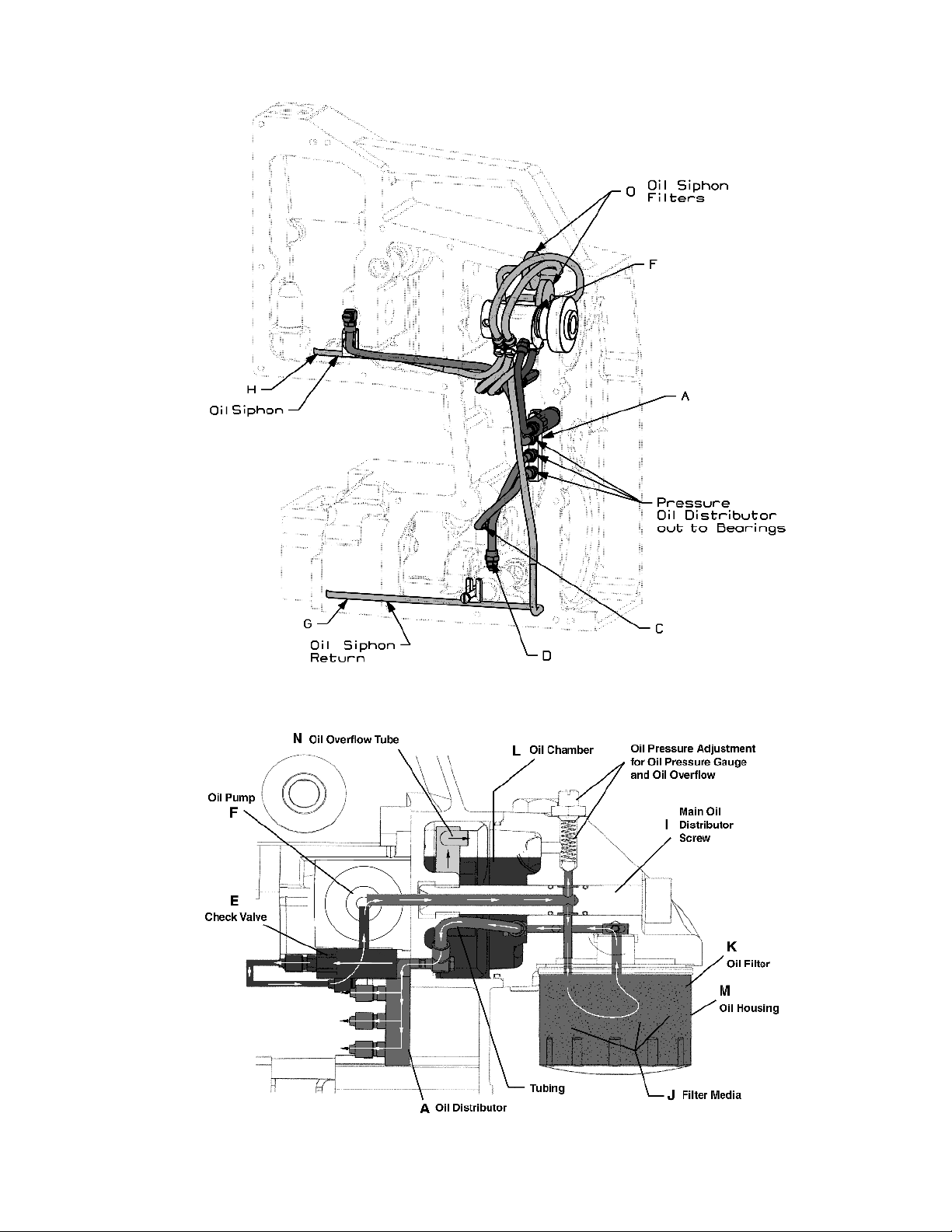
OIL FLOW DIAGRAM
The oiling system consists of pressurized oil 1 bar (15 PSI) through oil distributor (A) to three bearing areas (B), (C), (D).
From there, the oil is sent to strategic areas where oiling is necessary. First, the oil flows from the oil chamber (L) through
the check valve (E) into the 3.5mm portion of the gerotor in the oil pump (F), through the main oil distribution pipe (I) in the
oil housing (M) through the oil filter media (J), into the center of the oil filter (K), and out into the oil distributor (A) to the three
bearing areas. The check valve (E) provides security to prevent oil from draining back into the sewing machine when the
machine is idle.
There are two oil returns (H,G):
One return (G) is located in the lowest part of the feed area while the other return (H) is located in the lowest part of the needle
drive area. The oil in these areas is returned to the oil chamber (L) by suction through the gerotor oil pump (F). The oil is
ensured to stay in the oil chamber (L) by passing through an oil overflow tube (N) located in the oil chamber (L). The tube
opening is above the oil line so oil will not return to the feed drive and needle drive areas.
There is also an oil siphon filter (O) attached to each return line to ensure filtered oil at all times.
NOTE: If oil pressure gauge does not function, make sure oil return lines and line filters (O) are not filled with foreign material
preventing the oil to return. Check also to ensure that there is at least .060" (1.5 mm) gap between the end of the
return tube and the casting for the upper tube (H) and the feed cover for lower tube (G).
12
Page 13
13
Page 14

NEEDLE / LOOPER SYNCHRONIZATION
14
Page 15
1. Synchronize with TT148 Synchronization Gauge Kit
Turn handwheel in clockwise direction until looper shaft is approximately ¼" from the inside of the end cover.
Loosen the looper holder and move the holder to the left until its left edge touches the end cover and lock in
place with its screw.
Turn handwheel until the needle is at the bottom of the stroke and the looper holder is at the farthest position right.
Install the dial indicator (A) on the top of the machine. Set the indicator dial to zero.
Turn the handwheel clockwise until the looper holder touches the end cover. Record the number of revolutions and
final indicator reading.
Turn the handwheel counterclockwise until the looper holder touches the end cover once again. Record the
number of revolutions and final indicator reading. The readings should be the same as above.
The indicator must travel the same distance in the counterclockwise direction, a tolerance of ± .010" (.25mm) is
acceptable.
If the indicator is not the same distance, adjustment can be made by loosening the 3 screws (B) in lower belt
sprocket 10042, and moving slotted sprocket accordingly. If there is a lower number reading of the indicator on
the front travel, turn the slotted sprocket counterclockwise. If there is a lower number reading of the indicator at
the looper rear travel, turn the slotted sprocket clockwise.
After correct adjustment tighten the 3 screws (B) to 100 in lbs. (11.5nm)
Loosen the looper holder and return to its original position.
2. Synchronize without TT148 Synchronization Gauge Kit
If no indicator is available, set the synchronization measuring with a slide caliper or steel ruler.
Set the looper gauge to 3/32" (2.4mm).
Check the synchronization by moving the looper rearward behind the needle scarf. Continue moving the looper to the
left so that the top of the needle eye (C) is flush with the bottom of the looper blade (D). Measure the distance from
the looper tip to the left side of the needle (E).
Move the looper in the opposite direction to where the looper is in front of the needle. Set the top of the needle eye (C)
flush with the looper blade (D), the same as above. Measure the looper point to the left side of the needle. The second
measurement should be approximately 1/64" (0.4mm) less than the first (E).
If the measurement with the looper in front of the needle is less than the rear, turn the slotted sprocket counterclockwise.
If the measurement is less with the looper behind the scarf of the needle, turn the slotted sprocket clockwise.
Tighten the three screws (B) to 100 in. lbs. (11.5Nm).
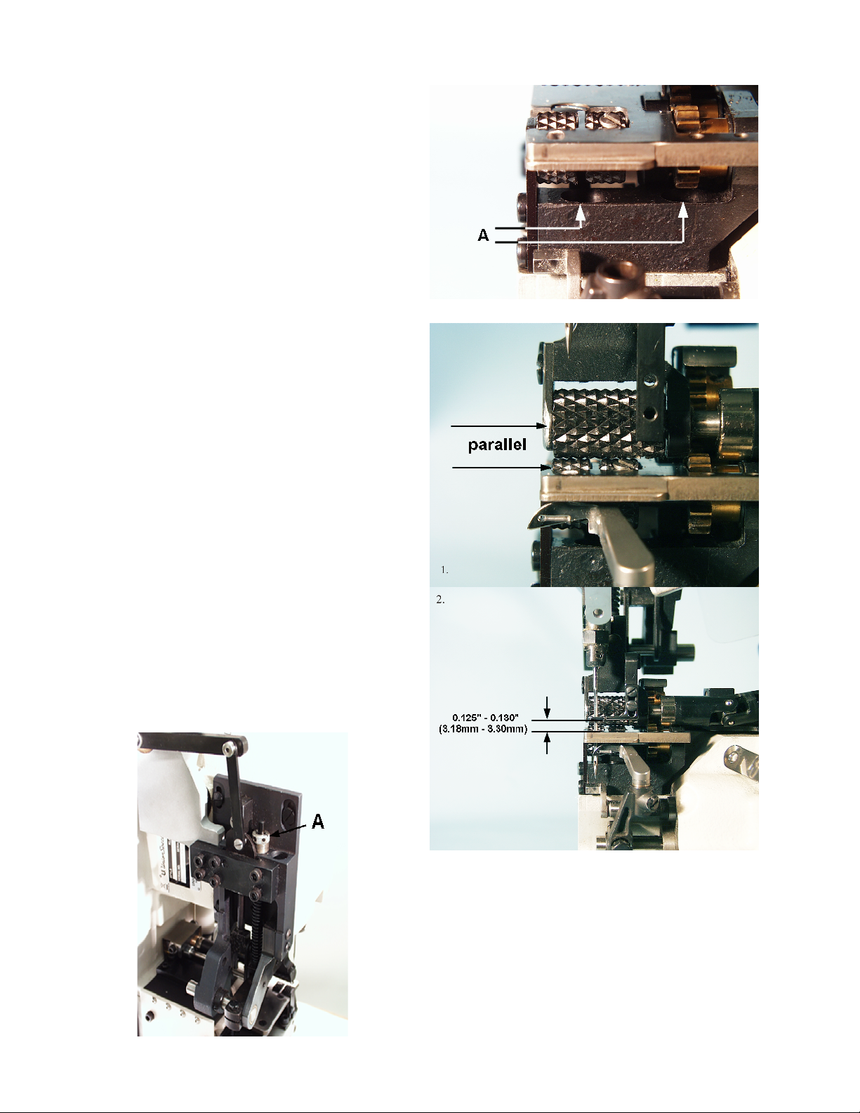
UPPER ROLLER DRIVE PLATE ASSEMBLY
The plate assembly is set up and down and front to back so that the
feed roller gear (A) on the end of the shaft engages with the feed
drive gear (B) in the lower roller housing without binds. The
centerline of the feed roller gear (A) on the drive plate assembly is
set to the rear of the centerline of the feed drive gear (B) in the lower
roller housing. A good starting position is to set the distance from
the back side of the back cover to the back of the adjustable plate
at 1 1/4" and parallel to the back cover. To make this adjustment,
loosen the (4) roller shaft housing screws (C) and move the housing
as required, then tighten the (4) screws securely.
After the front to back is set the height must be set so that the gears
engage with no binds and with a small amount of play. This
adjustment is made by loosening the (4) back cover screws (D) and
raising or lowering the plate as needed. A 10-32 thread screw can
be used in the threaded hole of the roller drive plate base to make
adjustment easier. Recheck the play in the gears after the screws
are tightened to ensure the setting is correct.
15
Page 16
LOWER ROLLER SETTING
The lower roller should be set left to right so the grooves
in the roller align with the guide wires in the throat plate
when it is against the left bushing in the roller support.
Moving the roller support left or right as needed then
tightening the two screws (A) for the roller support make
this adjustment. The roller is thrust to the left against the
bushing in the support while the drive gear is thrust against
the thrust washer and bushing in the right side of the
support. There should be no shake or bind in the roller after
this adjustment is made.
Note: Keep front edge of roller support parallel with
top edge of casting.
Note: When making this adjustment maintain play in
gears.
UPPER ROLLER AND PRESSER FOOT SETTING
1. Align the upper roller left to right so that it is parallel to the
lower roller; at this time the presser foot will also be
approximately centered to the needle. Set the roller front
to back so the when the roller is raised to its highest
position it does not hit the back of the needle. This
position is generally slightly to the rear of the lower roller.
Tighten the binder screw in the upper roller shank to
secure this position.
2. The presser foot is set with the upper roller in its lowest
position. The front to back position is set so that the
needle is centered in the radius of the presser foot slot.
The height of the presser foot is set so that there is 0.125"
- 0.130" (3.18mm - 3.30mm) between the bottom of the
presser foot and the top of the throat plate. When this
adjustment is made Loctite 222 screw lock must be
applied to the threads of the screws holding the presser
foot to the presser foot shank.
PRESSER FOOT PRESSURE
Turning presser foot presser adjustment screw (A)
clockwise increases the pressure, while counter clockwise
decreases the pressure. Set required force at 16 to 17 lbs.
(75 N).
16
Page 17
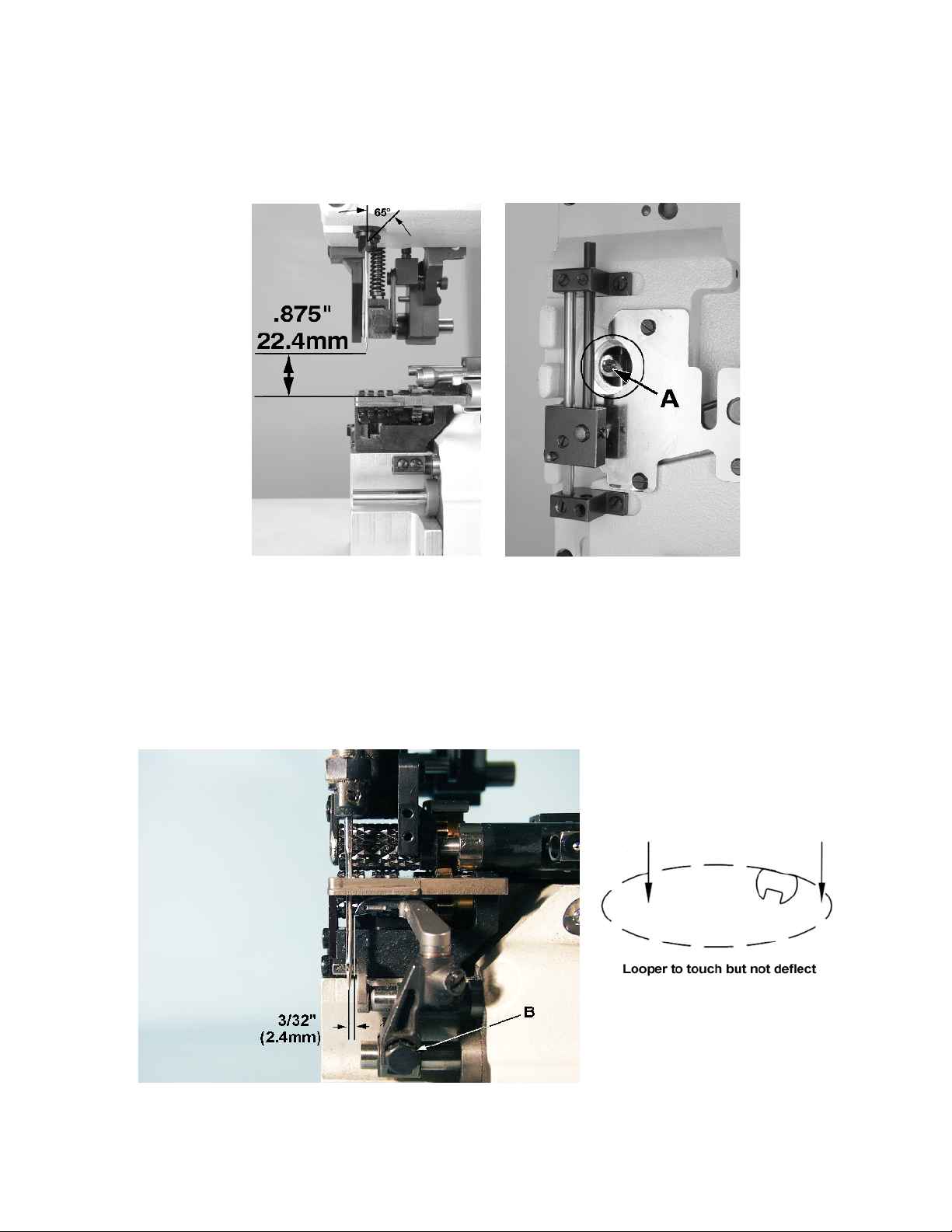
NEEDLE BAR SETTING
The needle holder must be set with its locking screw at a 60° angle to the right of center when viewed from the front of the
machine. Set the needle bar height so that when the needle is at top dead center in its travel, the distance from the tip of
the needle to the top of the throat plate is .875" (22.2mm) ± .020" (0.5mm). This adjustment is made by loosening screw
(A) inside the needle bar access hole (circled).
LOOPER SETTING
Set the looper so the point is 3/32" (.094", 2.4mm) from the centerline of the needle, when the looper is at its furthest position
to the right. Looper gauge number 21225-3/32 is available for setting the looper. While maintaining the 3/32" (.094", 2.4mm)
looper gauge set the looper front to back so the tip of the looper touches the scarf of the needle without deflecting the needle.
For adjustment, loosen screw (B) in the looper holder and move forward or backward as required. Retighten the screw (B)
in the looper holder and recheck the settings.
17
Note: If needle and looper settings are
incorrect skipping may occur.
Page 18

NEEDLE GUARD SETTING
1. Slip shaft of guard onto holder.
2. Position the guard about central in the clearance of the rubber sealing frame.
3. Position the guard so the guard shank clears the right side of the needle. Allow .040" to .080" (1 to 2 mm) so if the largest
diameter needle is ever used, it will clear.
4. Rotate adjustable pulley to bring the tip of the looper close to the right side of the needle, then push the guard to just
contact the needle and not deflec it. Tighten the guard with one screw. Rotate adjustable pulley in direction of arrow
to check this setting. If correct, tighten both screws very tight (will not have to be reset when changing stitch length).
NEEDLE THREAD CONTROL & TENSION
1. Needle thread take-up lever is set up and down to be 1 1/8" (28mm) from the center of the thread lever eyelet hole to
the underside of the top needle thread strike-off bracket at the top of it stroke. The lever is also set front to back to clear
the back of the thread guide by .040" (1mm).
2. Set the needle thread strike-off to 1 1/8" (28mm) between the bottom of the strike-off and the top of the strike-off support
bracket.
3. Set the needle thread eyelet directly to the left of the needle thread tension assembly to the bottom of its slot.
4. Set the needle thread tension to be heavy enough to pull up a good stitch without skipping.
18
Page 19

LOOPER THREAD CONTROL & TENSION
1. Set the cast-off edge of the take-up to be 1.97" (50mm) from the centerline of the looper take-up shaft.
2. Set the edge of the take-up to be .472" (12mm) to .512" (13mm) from the bottom of the outer cover when the takeup is at the end of its stroke.
3. At the same take-up position the distance from the centerline of the take-up eyelet hole to the edge of the take-up
should be .020" (0.5mm) to .059" (1.5mm).
4. Set the centerline of the take-up eyelet hole to be 1.89" (48mm) from the outside of the looper thread take-up shaft.
5. Set looper thread tension as light as possible yet stll control the looper thread.
LOOPER THREAD TAKE-UP SETTING
The looper thread should cast-off at the high point of the cam when the tip of the needle is 0.0 to 0.040" (0 to 1mm)
below the bottom of the looper blade.
19
Page 20

20
Page 21

Ref. No. Part No. Amt. Req.Description
*1.
*2.
*4.
*5.
*7.
10.
11.
12.
13.
14.
15.
16.
17.
18.
*19.
20.
*21.
*22.
*23.
*24.
25.
26.
*27.
28.
29.
3.
6.
8.
9.
10044AL
10054B
660-1033
10044CGL
10044DGL
660-1138
10044XGL
660-1137
660-1085
10044BK
TA0950806R0
10044AV
660-1021
660-1032
G10044T
999-256F
660-1018
10044AU
10044SGL
10044AH
10044BH
10044GGL
10044PGL
10044BJ
10044AW
CO66
10044GL
660-1138
999-256G
Bushing, needle bar, upper ......................................................
Bushing, needle bar, lower .......................................................
Lip Seal .........................................................................................
Bushing, needle thread control ...............................................
Bushing, needle thread control ...............................................
"O" Ring, for 10044DGL ..............................................................
Bushing, main shaft ....................................................................
"O" Ring, for 10054AB .................................................................
Lip Seal .........................................................................................
Bushing .........................................................................................
Plug ...............................................................................................
Bushing, needle guard ..............................................................
Washer, thrust ..............................................................................
Lip Seal .........................................................................................
Bushing, looper drive .................................................................
Lip Seal ..................................................................................
"O" Ring, for G10044T ..........................................................
Bushing, looper drive .................................................................
Bushing, looper drive cross shaft .............................................
Bushing .........................................................................................
Bushing .........................................................................................
Bushing, crank shaft ...................................................................
Bushing, knife drive ....................................................................
Bushing .........................................................................................
Bushing, needle guard ..............................................................
Plug ...............................................................................................
Bushing, knife drive ....................................................................
"O" Ring, for 10044GL .................................................................
Lip Seal .........................................................................................
BUSHINGS
1
1
1
1
1
1
1
1
1
1
1
1
1
1
1
1
1
1
1
1
1
1
1
1
1
1
1
1
1
* Secured with Loctite # 680
21
Page 22

22
Page 23

NEEDLE BAR DRIVE
Ref. No. Part No. Amt. Req.Description
1.
*10.
11.
12.
13.
14.
15.
16.
17.
18.
19.
*20.
21.
22.
23.
24.
25.
26.
27.
28.
29.
30.
*31.
*32.
33.
34.
35.
10096
2.
660-1141
3.
10017
4.
10095F
5.
10018B
6.
SS6110650TP
7.
794HSERV4-180/073
8.
10016B
9.
SS6150810SP
----10045N
10038A
10033H
SS8080410TP
SS6151812TP
10037
SS6152212SP
10083
10047B
----660-1037
660-1059
10091
22894AV
10048A
SS9151740CP
WP0651001SB
B1124804000
10016A
29126FP
-----
----SS6121610TP
10022G
CL21
Guard, needle bar .....................................................................
"O"Ring, for 10096 .......................................................................
Needle Bar ...................................................................................
Nut, hex ........................................................................................
Needle Head ...............................................................................
Screw .....................................................................................
Needle ..........................................................................................
Needle Bar Connection ............................................................
Screw .....................................................................................
Plug ........................................................................................
Connecting Rod, needle drive ................................................
Block, slide ...................................................................................
Collar, needle bar connection ................................................
Screw .....................................................................................
Screw ............................................................................................
Guide, needle drive ...................................................................
Screw ............................................................................................
Bracket, needle drive guide ....................................................
Crank Pin, needle drive .............................................................
Plug ........................................................................................
Bearing, caged needle .............................................................
Washer ..........................................................................................
Counterweight, needle drive ...................................................
Screw, set ..............................................................................
Lever, needle thread .................................................................
Screw .....................................................................................
Washer...................................................................................
Eyelet, thread.......................................................................
Connection ..........................................................................
Bearing Assembly .......................................................................
Screw, ball ............................................................................
Bearing, ball joint.................................................................
Screw ..............................................................................
Shaft, needle bar connection .................................................
Wick ..............................................................................................
1
1
1
1
1
1
1
1
1
1
1
1
1
2
2
1
2
1
1
1
1
1
1
2
1
1
1
1
1
1
1
1
2
1
1
*NOTE: Not sold separately
23
Page 24

24
Page 25

UPPER MAIN SHAFT
Ref. No. Part No. Amt. Req.Description
Main Shaft, upper .......................................................................
Plug ........................................................................................
Eccentric ......................................................................................
Screw, set .....................................................................................
Ring, retaining .............................................................................
BearingAssembly ........................................................................
Screw, set ..............................................................................
Sprocket, belt ..............................................................................
Screw, set .....................................................................................
Screw, set .....................................................................................
"O" Ring .........................................................................................
Flange Assembly .........................................................................
Flange ....................................................................................
Lip Seal ..................................................................................
Screw ............................................................................................
"O" Ring .........................................................................................
Hub ................................................................................................
Screw, set .....................................................................................
Pulley, belt ...................................................................................
Screw ............................................................................................
Washer ..........................................................................................
Screw ............................................................................................
Lever, belt tension ......................................................................
Belt, timing ...................................................................................
Roller, tension ..............................................................................
Bearing, ball ................................................................................
Screw ............................................................................................
10.
11.
12.
13.
14.
15.
16.
17.
18.
19.
20.
21.
22.
23.
24.
25.
26.
27.
1.
2.
3.
4.
5.
6.
7.
8.
9.
10022F
TA0370601M0
10040B
SS8660612TP
660-1029
29476ZS
SS8660612TP
10033M
SS8660612TP
SS8661212TP
660-1147
10042K
10042F
660-1103
SS4151215SP
660-212
10021D
22894AV
10021E
SS9151120CP
95953
SM6081802TP
10067
10042J
10076
660-1041
SS7110570SP
1
1
1
3
1
1
2
1
1
1
1
1
1
1
3
1
1
2
1
3
2
2
1
1
1
1
1
25
Page 26

26
Page 27

CRANKSHAFT ASSEMBLY
Ref. No. Part No. Amt. Req.Description
10.
11.
12.
13.
14.
15.
16.
17.
18.
19.
20.
21.
22.
23.
24.
25.
26.
27.
28.
29.
30.
31.
*32.
33.
*34.
35.
*36.
37.
38.
39.
40.
41.
42.
43.
44.
45.
*46.
*47.
48.
49.
50.
51.
*52.
53.
54.
55.
56.
57.
22574A
1.
35721H
2.
61321J
3.
35721G
4.
10021J
5.
95500
6.
10021N
7.
22650CF6
8.
10042M
9.
SS4111215SP
10033P
SS8660612TP
80885C
10082Y
10082Z
SS9151420TP
WP0621016SD
10042
10021B
22894AV
SS6151812TP
SS6151440SP
29126FY
SS4111215SP
10042C
660-1031
660-1103
660-1104
10042B
SS6121060SP
10035A
10045C
SS7121610SP
10013
22894AV
10022X
10040C
SS8660612TP
660-1028
29126FS
10095E
660-1047
10042A
SS8660612TP
96519
10045H
660-1036
10040A
SS1110840SP
10082D
22599F
10037E
10085
SS8661012TP
SS7080520SP
SM6043002TN
660-1035
Screw ............................................................................................
Pulley hub ....................................................................................
Handwheel ..................................................................................
Spacing Plate ..............................................................................
Handwheel Adapter Hub..........................................................
Screw ............................................................................................
Pulley .............................................................................................
Screw, set ..............................................................................
Bearing Housing Assembly ........................................................
Screw .....................................................................................
Bearing Adapter ..................................................................
Screw .....................................................................................
Ring, Bearing Retainer ........................................................
Cover, belt drive.........................................................................
Bearing Retainer .........................................................................
Screw ............................................................................................
Washer ..........................................................................................
Sprocket, feed drive ..................................................................
Hub ................................................................................................
Screw, set .....................................................................................
Screw ............................................................................................
Screw ............................................................................................
Crankshaft Assembly .................................................................
Screw .....................................................................................
Flange Cover .......................................................................
Bearing ..................................................................................
Lip Seal ..................................................................................
“O” Ring ................................................................................
Flange ....................................................................................
Screw .....................................................................................
Guide Fork ............................................................................
Connecting Rod ..................................................................
Screw ..............................................................................
Looper Drive Rocker ...........................................................
Screw, set ......................................................................
Crankshaft ............................................................................
Eccentric ......................................................................................
Screw, set ..............................................................................
“O” Ring .......................................................................................
Stitch Length Adj. Mechanism .................................................
Nut ..........................................................................................
Washer...................................................................................
Flange ....................................................................................
Screw, set ......................................................................
Pin ...................................................................................
Connecting Rod ..................................................................
Bearing, needle ...................................................................
Eccentric ...............................................................................
Screw .....................................................................................
Cover .....................................................................................
Screw, adjustment ..............................................................
Disc Segment .......................................................................
Disc ........................................................................................
Screw, set ......................................................................
Screw ..............................................................................
Screw .....................................................................................
Bearing .........................................................................................
3
1
1
1
1
2
1
3
1
2
1
2
1
1
1
3
3
1
1
2
3
3
1
3
1
1
1
1
1
2
1
1
4
1
1
1
1
2
1
1
2
4
1
2
1
1
1
1
2
1
1
1
1
2
2
2
1
*NOTE: Not sold separately
27
Page 28

28
Page 29

LOOPER DRIVE AND NEEDLE GUARD DRIVE
Ref. No. Part No. Amt. Req.Description
1.
10.
11.
12.
13.
14.
15.
16.
17.
18.
19.
20.
21.
22.
23.
2.
3.
4.
5.
6.
7.
8.
9.
10025A
10022E
SS8150510TP
10035
SS8660612TP
10008B
80137A
80137
10013B
22894AW
SS8660610TP
10043
10035C
SS7111410SP
29105BF
10035B
SS9090640SP
10035E
10088
10045J
CL21
10045K
CL21
Needle Guard ..............................................................................
Shaft, needle guard ....................................................................
Screw, set ..............................................................................
Fork, needle guard ......................................................................
Screw, set ..............................................................................
Looper ...........................................................................................
Collar 1 mm thick (if required only) ..........................................
Collar 1.8 mm thick (if required only) .......................................
Looper Holder ..............................................................................
Screw .....................................................................................
Screw .....................................................................................
Looper Bar ....................................................................................
Fork, connecting .........................................................................
Screw .....................................................................................
Fork Assembly, looper drive .......................................................
Fork, connection ..................................................................
Screw ..............................................................................
Joint, looper drive ................................................................
Ball ..........................................................................................
Pin, link ...................................................................................
Wick .......................................................................................
Pin, link ..........................................................................................
Wick ...............................................................................................
1
1
2
1
1
1
1
1
1
1
1
1
1
1
1
1
1
1
1
1
1
1
2
29
Page 30

30
Page 31

DRIVE PARTS AND THROAT PLATE SUPPORTS
Ref. No. Part No. Amt. Req.Description
10.
11.
12.
13.
14.
15.
16.
17.
18.
19.
20.
21.
22.
23.
24.
25.
26.
27.
28.
29.
30.
31.
32.
33.
34.
35.
36.
37.
38.
39.
40.
41.
42.
43.
44.
45.
46.
47.
48.
49.
50.
51.
52.
53.
54.
55.
56.
29126GA
1.
22652B6
2.
RM3293-6
3.
10082AB
4.
22652A6
5.
10083AJ
6.
22653B8
7.
10039G
8.
RM3058-10
9.
22650AA2
10039K
RM2808-3
10022Y
10039L
RM2810-1
10039C
RM2808-3
10086C
22735B
12957E
10064A
10062G
RM4414-1
10022Z
SS4150915SP
10080F
22653D8
6042A
10080E
10022P
10033C
SS8660612TP
—
RM3058-2
22651CD3
AS47-229BR
10022S
RM3144-8
10022R
GR-999-196
10045L
CL21
670N9
SS8660612TP
10039E
RM2815-2
10039D
RM2815-2
10039F
RM2815-2
10062D
SS6151412TP
RM2984B
RM3993-7
41358
23215BH1-7/16
Upper Roller Drive Assembly.....................................................
Socket Head Cap Screw ...................................................
Washer...................................................................................
Cover, rear gear..................................................................
Socket Head Cap Screw ...................................................
Block, cover mount .............................................................
Screw .....................................................................................
Housing, roller shaft .............................................................
Collar .....................................................................................
Screw ..............................................................................
Gear, feed roller ..................................................................
Screw ..............................................................................
Drive Shaft, upper ...............................................................
Universal Joint ......................................................................
Screw ..............................................................................
Gear, roller drive .................................................................
Screw ..............................................................................
Thrust Washer .......................................................................
Screw, folder pivot ..............................................................
Washer...................................................................................
Swing Arm, folder ................................................................
Plate, gear mounting..........................................................
Button Head Cap Screw ....................................................
Connection Shaft, upper ...................................................
Screw ............................................................................................
Support, throat plate .................................................................
Screw ............................................................................................
Washer ..........................................................................................
Support, throat plate front ........................................................
Shaft, drive ...................................................................................
Collar .....................................................................................
Screw ..............................................................................
Plug ........................................................................................
Collar ............................................................................................
Screw .....................................................................................
Washer ..........................................................................................
Feed Rocker Shaft ......................................................................
E-ring .............................................................................................
Shaft, drive gear .........................................................................
Plug, oil pan .................................................................................
Link Pin ..........................................................................................
Wick .......................................................................................
Clutch, feed driving ...................................................................
Screw .....................................................................................
Feed Drive Gear .........................................................................
Screw
.....................................................................................
Intermediate Gear .....................................................................
Screw .....................................................................................
Intermediate Gear .....................................................................
Screw .....................................................................................
Drive Gear Support Plate ..........................................................
Screw ............................................................................................
Screw ............................................................................................
Lockwasher ..................................................................................
Washer ..........................................................................................
Folder, for 1-7/16" Tape 1/2" opening .......................................
1
2
2
1
1
1
4
1
1
1
2
2
1
1
1
1
1
4
1
1
1
1
4
1
2
1
1
1
1
1
1
2
2
1
1
2
1
1
1
1
1
1
1
1
1
1
1
1
1
1
1
1
2
2
2
1
31
Page 32

44
45
29
43
31
30
42
41
40
38
39
36
37
11
12
13
26
27
26
28
18
23
16
25
17
15
19
24
14
32
20
21
22
35
34
33
32
Page 33

PRESSER FOOT LIFT
Ref. No. Part No. Amt. Req.Description
1.
2.
3.
4.
5.
6.
7.
8.
9.
10.
11.
12.
13.
14.
15.
16.
17.
18.
19.
20.
21.
22.
23.
24.
25.
26.
27.
28.
29.
30.
31.
32.
33.
34.
35.
36.
37.
38.
39.
40.
41.
42.
43.
44.
45.
29126FZ
36236J
660-336
10038F
10044BL
10043A
NS6120310SP
2015N
10032K
10037C
C10030Y
10056
10083AF
RM4489-1
10033L
SS8110740SP
10038E
10035D
SD0640326TP
G671G20
667H40
10083AG
10067G
SS8120410SP
SS9151740CP
SS6152212SP
10083AH
10062F
10022AA
10038G
10035J
RM4475-1
10096D
6042A
SS6152212SP
SS7151310TP
SS6151040SP
RM4316-29
10056A
RM3239-1
RM3293-6
RM3993-3
RM4489-1
10056C
RM3306-3
Presser Foot Lift Assembly..........................................................
Screw, socket shoulder ......................................................
Needle bearing ...................................................................
Link Block, follower to shaft ...............................................
Bushing, feed lift shaft ........................................................
Shaft, feed lift .......................................................................
Nut, hex .................................................................................
Washer...................................................................................
Presser Spring .......................................................................
Bushing, presser foot lifter guide.......................................
Screw, regulator ..................................................................
Presser Rod Bar ....................................................................
Presser Foot Lift Support .....................................................
Button Head Cap Screw ....................................................
Collar .....................................................................................
Screw ..............................................................................
Block, shaft linkage .............................................................
Presser Foot Lifter Link .........................................................
Screw, shoulder ...................................................................
Fork, hinge
Dowel Pin ..............................................................................
Lift Support Bracket .............................................................
Presser Foot Lever................................................................
Screw, set ......................................................................
Screw ..............................................................................
Screw .....................................................................................
Mount, feed roll lift ..............................................................
Plate, shaft support mounting...........................................
Shaft .......................................................................................
Cam .......................................................................................
Connecting Link, feed lift ..................................................
Screw .....................................................................................
Needle Bar Guard ...............................................................
Washer...................................................................................
Screw .....................................................................................
Screw .....................................................................................
Screw .....................................................................................
Screw .....................................................................................
Arm, connecting, feed lift .................................................
Washer...................................................................................
Washer...................................................................................
Washer, spring......................................................................
Screw .....................................................................................
Feed Lift Arm Extension ......................................................
Screw .....................................................................................
............................................................................
1
2
1
1
1
1
2
1
1
1
1
1
1
2
1
1
1
2
2
1
1
1
1
1
1
6
1
1
1
1
1
1
1
1
1
2
1
1
1
1
1
1
1
1
1
33
Page 34

34
Page 35

Ref. No. Part No. Amt. Req.Description
1.
2.
3.
4.
5.
6.
7.
*8.
9.
10.
11.
12.
13.
14.
15.
16.
17.
18.
19.
20.
21.
22.
23.
AS96-701
660-3003
10093T
WP0531000SE
SS6121210SP
SM6051202TP
10093AR
10093AY
660-3003
660-3004
10093CL
660-3004
10093CN
10093U
10093AK
660-3004
18C94-23
660-3004
AS96-700
NS6120310SP
WP0531000SE
10093T
SS6123010SP
Oil Tube, suction .........................................................................
Rotary Fitting ................................................................................
Clamp, oil tube ...........................................................................
Washer ..........................................................................................
Screw ............................................................................................
Screw ............................................................................................
Oil Deflection Plate ....................................................................
Oil Pump Assembly .....................................................................
Elbow Fitting ................................................................................
Straight Fitting..............................................................................
Stand-off ......................................................................................
Straight Fitting ......................................................................
Stand-off ......................................................................................
Oil Distributor ...............................................................................
Screw, hollow ..............................................................................
Straight Fitting..............................................................................
Screw ............................................................................................
Straight Fitting..............................................................................
Oil Tube, suction .........................................................................
Nut .................................................................................................
Washer ..........................................................................................
Clamp, oil tube ...........................................................................
Screw ............................................................................................
OIL PUMP
1
1
2
2
5
3
1
1
5
1
3
1
1
1
1
3
1
2
1
1
1
1
1
* Sold only as a tested assembly
35
Page 36

36
Page 37

Ref. No. Part No. Amt. Req.Description
1.
2.
3.
4.
5.
6.
7.
8.
10093AH
10093-4
10093-2
10093AD
10093AF
10093-7
56393N
660-1071
Oil Tube, 220mm Long ...............................................................
Oil Tube, 178mm Long ...............................................................
Oil Tube, 330mm Long ...............................................................
Oil Tube, 100mm Long ...............................................................
Oil Tube, 120mm Long ...............................................................
Oil Tube, 117mm Long ...............................................................
Spring ............................................................................................
Oil Filter .........................................................................................
OIL TUBES
1
4
1
1
3
1
13
2
37
Page 38

38
Page 39

OIL DISTRIBUTOR ASSEMBLY
Ref. No. Part No. Amt. Req.Description
1.
2.
*3.
4.
5.
6.
7.
8.
9.
10.
11.
12.
13.
14.
15.
16.
17.
18.
19.
20.
21.
22.
23.
24.
25.
26.
10084
GR10093A
----WP0531000SE
SM6052002TP
671D57
10093AU
P-199-196
10093CM
671D55
660-1125
660-1124
10093AV
22599N
999-124BCO
10088C
10032A
GR-660-1068
22599N
22599M
660-1123
660-1025
660-3003
10093AT
660-1027
660-1126
Gasket ..........................................................................................
Oil Distributor ...............................................................................
Oil Tube .................................................................................
Washer ..........................................................................................
Screw ............................................................................................
Oil Level Gauge ..........................................................................
Oil Pressure Gauge.....................................................................
Screw, plug, oil drain .................................................................
Tube, threaded ...........................................................................
Oil Filter .........................................................................................
Screw ............................................................................................
Washer ..........................................................................................
Housing, distribution ...................................................................
Screw, set .....................................................................................
Stick-on Label ..............................................................................
Ball .................................................................................................
Spring ............................................................................................
Nut .................................................................................................
Screw, set .....................................................................................
Screw, plug ..................................................................................
“O” Ring .......................................................................................
“O” Ring .......................................................................................
Fitting, rotary ................................................................................
Oil Distribution Stud ....................................................................
“O” Ring .......................................................................................
Nut .................................................................................................
1
1
1
1
1
1
1
1
1
1
1
1
1
1
1
1
1
1
1
2
1
1
1
1
1
1
NOTE: Not sold separately
*
39
Page 40

49
50
4
53
52
54
48
51
61
55
44
43
40
56
58
60
57
47
59
46
45
29
44
43
39
42
30
45
41
38
37
40
34
35
36
31
Page 41

NEEDLE THREAD CONTROL
Ref. No. Part No. Amt. Req.Description
Screw ..................................................................................................
Screw ..................................................................................................
Collar ..................................................................................................
Shaft, roller lift arm ............................................................................
Cover ..................................................................................................
Screw ..................................................................................................
Support, thread control ..................................................................
Screw, set ...........................................................................................
Pin ........................................................................................................
Guide, thread ...................................................................................
Pin ................................................................................................
Screw...........................................................................................
Pin ................................................................................................
Screw, set ...................................................................................
Pin ................................................................................................
Screw ..................................................................................................
Guide, thread ...................................................................................
Guide, thread ...................................................................................
Screw, set ...........................................................................................
Support, thread guide .....................................................................
Shaft Support Plate, rear .................................................................
Shaft Support Plate, front ...............................................................
Nut, tension regulator......................................................................
Pin ................................................................................................
Ferrule, tension ..................................................................................
Spring ..................................................................................................
Bushing ...............................................................................................
Disc, tension ......................................................................................
Bushing ...............................................................................................
Knob, tension .....................................................................................
Handle knob .....................................................................................
Washer ................................................................................................
Washer, lock ......................................................................................
Screw ...................................................................................................
Nut .......................................................................................................
Latch ...................................................................................................
Nut.......................................................................................................
Stop. lock ...........................................................................................
Nut .......................................................................................................
Extension Spring, latch ....................................................................
Screw ..................................................................................................
Screw ..................................................................................................
Washer, lock ......................................................................................
Washer ................................................................................................
Screw ..................................................................................................
Mounting Bracket, shield ................................................................
Tension Release Lever .....................................................................
Screw
..................................................................................................
Guide, thread ...................................................................................
Washer ................................................................................................
Screw ..................................................................................................
Latch Mounting Plate ......................................................................
Nut .......................................................................................................
Needle Protection Shield Assembly .............................................
Nut ...............................................................................................
Bracket Holder ..........................................................................
Bracket........................................................................................
Washer, spring ...........................................................................
Screw...........................................................................................
Screw...........................................................................................
Protective Shield .......................................................................
10.
*11.
12.
13.
14.
15.
16.
17.
18.
19.
20.
21.
22.
23.
*24.
25.
26.
27.
28.
29.
30.
31.
32.
33.
34.
35.
36.
37.
38.
39.
40.
41.
42.
43.
44.
45.
46.
47.
48.
49.
50.
51.
52.
53.
54.
55.
56.
57.
58.
59.
60.
61.
1.
2.
3.
4.
5.
6.
7.
8.
9.
22653B24
22650CD4
RM3058-11
10038B
10082Q
SS6121050SP
10066C
SS8660410SP
10047
10066B
----SS7080520SP
10047J
SS8660410SP
10047H
SS1120710SP
10068B
10066D
28C
80858BX1
10038D
10038C
10092
----39592AK
110-4
10044B
80676A
GR-10044A
10092A
50667A
RM3293-6
RM3993-3
22738D
60078Z
10047Q
10047R
SC524
RM3211-14
10032G
22767A
RM4485-2
RM3993-8
RM3293-1
22659B8
10083AD
10067F
RM4375-1
51858
WP0482086SD
RM2984B
10062E
651H
99682XCB
NS6620320SP
50383AE
50385AD
WZ0641510KP
SD0640323TP
SS6110610TP
99682XC3
4
1
1
1
1
6
2
4
1
1
1
2
1
1
1
1
1
1
1
1
1
1
1
1
1
1
1
2
1
1
1
2
2
1
1
1
1
1
1
1
1
1
2
2
2
1
1
1
1
1
1
1
1
1
1
1
1
1
1
2
1
NOTE: Not sold separately
*
41
Page 42

42
4
5
6
7
8
9
10
11
22
Page 43

LOOPER THREAD CONTROL
Ref. No. Part No. Amt. Req.Description
1.
4.
5.
6.
7.
8.
9.
10.
11.
12.
13.
14.
15.
16.
17.
18.
19.
20.
21.
22.
10066D
2.
80858BX-1
3.
28C
43266
39580F
51192G
51192B
51292
109
39592AR8
51292C
10068D
10068E
SS6121050SP
10068C
SS1120710SP
10023B
10023
10048
SS9151630CP
WP0480856SP
10082W
Guide, thread..............................................................................
Support, thread guide ...............................................................
Screw, set ....................................................................................
Nut .................................................................................................
Washer.............................................................................................
Eyelet .............................................................................................
Ferrule ...........................................................................................
Tension Post....................................................................................
Tension Disc .................................................................................
Tension Spring ..............................................................................
Tension Nut ...................................................................................
Guide, thread..............................................................................
Eyelet .....................................................................................
Screw ............................................................................................
Guide, thread..............................................................................
Screw ............................................................................................
Hook, thread ...............................................................................
Take-up, thread ..........................................................................
Lever .............................................................................................
Screw .....................................................................................
Washer..........................................................................................
Cover ............................................................................................
1
1
1
1
1
1
1
1
2
1
1
1
2
5
1
1
1
1
1
1
1
1
43
Page 44

441145
Page 45

FRONT AND LOOPER COVERS
Ref. No. Part No. Amt. Req.Description
9.
10.
11.
1.
2.
3.
4.
5.
6.
7.
8.
10084C
SS8120740SP
22894BM
10082P
660-1067
660-1094
96535
660-1127
10067E
TA2351004R0
SS6151812TP
Seal, quad-ring ...........................................................................
Screw, set .....................................................................................
Screw ............................................................................................
Cover, front .................................................................................
Pin ...........................................................................................
Pin ...........................................................................................
Pin ...........................................................................................
Lip Seal ..................................................................................
Stand-off, metering tape cutter ..............................................
Plug..................................................................................................
Screw............................................................................................
1
4
14
1
2
2
2
2
2
1
2
Page 46

12
13
14
15
16
17
46
19
18
Page 47

Ref. No. Part No. Amt. Req.Description
SS1120710SP
1.
10082S
2.
10083AA
3.
SS8110510SP
4.
10083AB
5.
C50041J
6.
10022Q
7.
10033N
8.
RM2810-1
9.
10.
11.
12.
*13.
*14.
*15.
*16.
*17.
*18.
*19.
* Purchase complete as 29480BEK
10082T
SS4120615SP
10062L
22658D8
RM3293-1
10077
10022AB
10083AP
SS6151812TP
RM4485-2
Screw ............................................................................................
End Cover ....................................................................................
Support Block, swing cover ......................................................
Screw ............................................................................................
Swing cover, mounting bracket ..............................................
Spring Plunger .............................................................................
Shaft, swing cover ......................................................................
Collar, swing cover shaft...........................................................
Screw .....................................................................................
Swing Cover ................................................................................
Screw ............................................................................................
Tape guide plate..........................................................................
Screw..............................................................................................
Washer...........................................................................................
Front roller......................................................................................
Front roller shaft............................................................................
Front roller bracket......................................................................
Screw..............................................................................................
Screw..............................................................................................
COVERS
6
1
1
1
1
1
1
1
1
1
2
1
1
1
1
1
1
2
1
47
Page 48

34
16
2
17
19
20
21
18
222324
25
1
3
48
Page 49

BACK AND RIGHT COVERS
Ref. No. Part No. Amt. Req.Description
22894BM
10.
11.
12.
13.
*14.
*15.
16.
17.
18.
19.
20.
21.
22.
23.
24.
25.
26.
27.
28.
29.
30.
31.
32.
33.
34.
1.
2.
3.
4.
5.
6.
7.
8.
9.
SS7151210TP
10082Y
10068G
10058G
10084D
10082R
10094
10093AM
660-3003
SS8150710SP
660-705
670G224
-----
----22839C
56342J
23306AH
51292C
51292F14
22845N
23306AJ
54480
23306AN
23306AL
SS6151812TP
22799AK
660-1038
10082V
10082G
660-1024
660-1069
95076
10037P
Screw ............................................................................................
Screw ............................................................................................
Cover ............................................................................................
Looper Thread Eyelet .................................................................
Thread Eyelet...............................................................................
Gasket, filter housing ..................................................................
Cover, filter housing ....................................................................
Vent ...............................................................................................
Oil Tube 6x4; 0.33 m long ...........................................................
Oil Fitting, rotary ...........................................................................
Screw, set .....................................................................................
“O” Ring ........................................................................................
Plug ................................................................................................
Pin ..................................................................................................
Plate, style ....................................................................................
Screw ............................................................................................
Washer...................................................................................................
Tape Tension Assembly ...............................................................
Nut ..........................................................................................
Spring .....................................................................................
Screw .....................................................................................
Tension Plate ........................................................................
Support Spacer ....................................................................
Tension Post ..........................................................................
Tension Bracket ....................................................................
Screw ............................................................................................
Screw, plug...................................................................................
"O" Ring .........................................................................................
Back Cover ..................................................................................
Cover ............................................................................................
“O” Ring ........................................................................................
“O” Ring ........................................................................................
Screw, flat head ...........................................................................
Tape Tension Mounting Plate...........................................................
9
1
1
1
1
1
1
1
1
1
1
1
1
4
1
1
1
1
1
1
1
2
1
1
1
8
1
1
1
1
1
1
3
1
* NOTE: Not sold separately
49
Page 50

9
8
12
11
10
1
2
7
3
6
4
13
5
14
15
16
21
17
20
19
23
22
18
27
25
26
24
28
29
50
Page 51

Ref. No. Part No. Amt. Req.Description
1.
2.
3.
4.
5.
-
-
6.
7.
8.
9.
10.
11.
12.
13.
14.
15.
16.
17.
18.
19.
20.
21.
22.
23.
-
-
24.
25.
26.
27.
28.
29.
10039M
SS9151420TP
SS7190850SP
10039N
10075J
10075P
10075R
22580
10022AC
22652K8
40-107
22768B
10030AA
10020G
SS7151210SP
10096A
22599L
10024G
10086C
10039C
RM2808-3
10039K
RM2808-3
98
10075L
10075Q
10075N
10022AE
RM2797-2
10039P
10022W
10039R
SS7090710SP
Shank, upper roller .....................................................................
Screw, set ......................................................................
Screw................................................................................................
Upper Feed Roller Support Plate................................................
Upper Feed Roller, 16 teeth Diamond knurl.............................
Upper Feed Roller, 10 TPI (Optional).........................................
Upper Feed Roller, 12 TPI (Optional).........................................
Screw ............................................................................................
Upper Feed Roller Shaft................................................................
Screw ............................................................................................
Washer ..........................................................................................
Screw ............................................................................................
Presser Foot Shank ......................................................................
Presser Foot Bottom ....................................................................
Screw ............................................................................................
Gear Cover..................................................................................
Screw ............................................................................................
Throat Plate, tape edge............................................................
Thrust Washer ..............................................................................
Puller Drive Gear .........................................................................
Screw ............................................................................................
Feed Drive Gear .........................................................................
Screw ............................................................................................
Screw ............................................................................................
Lower Feed Roller, 16 teeth Diamond Knurl...........................
Lower Feed Roller, 10 TPI (Optional).........................................
Lower Feed Roller, 12 TPI (Optional)..........................................
Lower Roller Shaft .......................................................................
Screw ............................................................................................
Lower Roller Base........................................................................
Gear Support Shaft.....................................................................
Lower Roller Support Plate............................................................
Screw...............................................................................................
SEWING PARTS
1
1
2
1
1
1
1
1
1
2
2
2
1
1
1
1
2
1
2
1
2
1
2
1
1
1
1
1
2
1
1
1
2
51
Page 52

52
Page 53

Ref. No. Part No. Amt. Req.Description
1.
22933105
2.
22933006
3.
B9204804000
4.
WR83
5.
794HSERV4-180/073
6.
28604R
*7.
*8.
*9.
*10.
*11.
*12.
*13.
*14.
*15.
* Extra send and charge
29480BEM
61377Q
10032E
22799AP
10047P
10064A
RM2984B
RM3993-7
41358
Screw Driver.................................................................................
Screw Driver.................................................................................
Tweezers .......................................................................................
Allen Wrench 5mm .....................................................................
Needle ..........................................................................................
Oil Bottle 0.5 liter .........................................................................
Folder change kit .......................................................................
Washer...................................................................................
Spring .....................................................................................
Shoulder Screw ....................................................................
Hairpin Cotter Pin ................................................................
Swing Arm, Folder ................................................................
Screw .....................................................................................
Screw .....................................................................................
Washer...................................................................................
ACCESSORIES
1
1
1
1
10
1
1
2
1
1
1
1
2
2
2
53
Page 54

NUMERICAL INDEX OF PARTS
Part No.
Page
10008B ......... 29
10013 ........... 27
10013B ......... 29
10016A ......... 23
10016B ......... 23
10017 ........... 23
10018B ......... 23
10020G ......... 51
10021B ......... 27
10021D ......... 25
10021E ......... 25
10021J ......... 27
10021N ......... 27
10022AA ....... 33
10022AB........47
10022E ......... 29
10022F ......... 25
10022G ......... 23
10022Q ......... 47
10022R ......... 31
10022S ......... 31
10022W ......... 51
10022X ......... 27
10022Y ......... 31
10022Z ......... 31
10022AC.......51
10022AE.........51
10023 ........... 43
10023B ......... 43
10024G ......... 51
10025A ......... 29
10030AA ....... 51
10032A ......... 39
10032E ......... 53
10032G ......... 41
10033C ......... 31
10033H ......... 23
10032K..........33
10033L ......... 33
10033M ......... 25
10033N ......... 47
10033P ......... 27
10035 ........... 29
10035A ......... 27
10035B ......... 29
10035C ......... 29
10035D ......... 33
10035E ......... 29
10035J ......... 33
10037 ........... 23
10037C .........
33
10037E ......... 27
110037P..........49
10038A ......... 23
10038B ......... 41
10038C ......... 41
10038D ......... 41
10038E ......... 33
Part No.
Page
10038F ......... 33
10038G ......... 33
10039M ......... 51
10039C .... 31, 51
10039D ......... 31
10039E ......... 31
10039F ......... 31
10039G ......... 31
10039K .... 31, 51
10039L ......... 31
10039N........51
10039P........51
10039R.........51
10040A ......... 27
10040B ......... 25
10040C ......... 27
10042 ........... 27
10042A ......... 27
10042B ......... 27
10042C ......... 27
10042F ......... 25
10042J ......... 25
10042K ......... 25
10042M ......... 27
10043 ........... 29
10043A ......... 33
10044AH ....... 21
10044AL ....... 21
10044AU ....... 21
10044AV ....... 21
10044AW ....... 21
10044B ........ 41
10044BH ....... 21
10044BJ ....... 21
10044BK ....... 21
10044BL ....... 33
10044CGL ..... 21
10044DGL ..... 21
10044GGL ..... 21
10044GL ....... 21
10044PGL ..... 21
10044SGL ..... 21
10044XGL ..... 21
10045C ......... 27
10045H ......... 27
10045J ......... 29
10045K ......... 29
10045L ......... 31
10045N ......... 23
10047 ........... 41
10047B ......... 23
10047H ......... 41
10047J ......... 41
10047P ......... 53
10047Q ......... 41
10047R ......... 41
10048 ........... 43
10048A ......... 23
Part No.
Page
10054B ......... 21
10056 ........... 33
10056A ......... 33
10056B ......... 41
10056C ......... 33
10058G ......... 49
10062D ......... 31
10062E ......... 41
10062F ......... 33
10062G ......... 31
10062L...........47
10064A ....41, 53
10066B ......... 41
10066C ......... 41
10066D .... 41, 43
10067 ........... 25
10067E ......... 45
10067F ......... 41
10067G ......... 33
10068B ......... 41
10068C ......... 43
10068D ......... 43
10068E ......... 43
10068G ......... 49
10075J ......... 51
10075L ......... 51
10075N...........51
10075P...........51
10075Q..........51
10075R..........51
10076 ........... 25
10077...............
47
10080E ......... 31
10080F ......... 31
10082D ......... 27
10082G ......... 49
10082P ......... 45
10082Q ......... 41
10082R ......... 49
10082S ......... 47
10082T ......... 47
10082V ......... 49
10082W ......... 43
10082Y .... 27, 49
10082Z ......... 27
10082AB..............31
10083 ........... 23
10083AA ....... 47
10083AB ....... 47
10083AD ....... 41
10083AF ....... 33
10083AG ....... 33
10083AH ....... 33
10083AJ ....... 31
10083AP.........47
10084 ........... 39
10084C ......... 45
10084D ......... 49
Part No.
Page
10085 ........... 27
10086C .... 31, 51
10088 ........... 29
10088C ......... 39
10091 ........... 23
10092 .......... 41
10092A ........ 41
10093-2 ....... 37
10093-4 ....... 37
10093-7 ....... 37
10093AD ....... 37
10093AF ....... 37
10093AH ....... 37
10093AK ....... 35
10093AM ....... 49
10093AR ....... 35
10093AT ....... 39
10093AU ....... 39
10093AV ....... 39
10093AY ....... 35
10093CL ....... 35
10093CM ....... 39
10093CN ....... 35
10093T ......... 35
10093U ......... 35
10094 ........... 49
10095E ......... 27
10095F ......... 23
10096 ........... 23
10096A ......... 51
10096D ......... 33
109............43
110-4 ........... 41
12957E ......... 31
18C94-23 ..... 35
2015N ......... 33
22574A ......... 27
22599F ......... 27
22599L ......... 51
22599M ......... 39
22599N ......... 39
22650AA2 ..... 31
22650CD4 ..... 41
22651CD3 ..... 31
22650CF6 ..... 27
22652A6 ....... 31
22652B6 ....... 31
22652D12 ..... 33
22652K8 ....... 51
22653B24 ........ 41
22653B8 ......... 31
22653D8 ......... 31
22653D8..........47
22658D12 ....... 41
22659B8 ......... 41
22735B ......... 31
22738D ......... 41
22767A ......... 41
54
Page 55

NUMERICAL INDEX OF PARTS
Part No.
Page
22768B ......... 51
22799AK ....... 49
22799AP ....... 53
22839C........49
22845N ......... 49
22894AV .23, 25, 27
22894AW ......... 29
22894BM .... 45, 49
22933006 ....... 53
22933105 ....... 53
23215BH1-7/16 .. 31
23306AH ....... 49
23306AJ ....... 49
23306AL ....... 49
23306AN ....... 49
28604R ......... 53
28604X ......... 39
28C ........ 41, 43
29105BF ....... 29
29126FP ....... 23
29126FS ....... 27
29126FY ....... 27
29126FZ ....... 33
29126GA ....... 31
29476ZS ........ 25
29480BEK.........47
35721G ......... 27
35721H ......... 27
36236J ......... 33
39543R ......... 33
39580F.........43
39592AK ......... 41
39592AR8..........43
40-107 ......... 51
41358 .......41, 53
43266........43
50383AE ....... 41
50385AD ....... 41
50667A ......... 41
51192B...........43
51192G...........43
51292........43
51292C ......43, 49
51292F14 ....... 49
51858 ........... 41
54480 ........... 49
56342J........
49
56393N ......... 37
60078Z ......... 41
6042A ..... 31, 33
61321J ......... 27
61377Q ........ 53
651H ............. 41
660-1018 ....... 21
660-1021 ....... 21
660-1024 ....... 49
660-1025 ....... 39
660-1027 ....... 39
Part No.
Page
660-1028 ....... 27
660-1029 ....... 25
660-1031 ....... 27
660-1032 ....... 21
660-1033 ....... 21
660-1035 ....... 27
660-1036 ....... 27
660-1037 ....... 23
660-1038 ....... 49
660-1041 ....... 25
660-1047 ....... 27
660-1055 ....... 25
660-1059 ....... 23
660-1067 ....... 45
660-1069 ....... 49
660-1071 ....... 37
660-1085 ....... 21
660-1094 ....... 45
660-1103 ... 25, 27
660-1104 ....... 27
660-1123 ....... 39
660-1124 ....... 39
660-1125 ....... 39
660-1126 ....... 39
660-1127 ....... 45
660-1137 ....... 21
660-1138 ....... 21
660-1141 ....... 23
660-1147 ....... 25
660-212 ........ 25
660-336 ........ 33
660-3003 ... 35, 39,49
660-3004 ....... 35
660-705 ........ 49
667H40 ....... 33
670G224 ....... 49
670N9 ......... 31
671D55 ........ 39
671D57 ........ 39
794HSERV4-180/073 ... 23
794HSERV4-180/073 ... 53
80137 ........... 29
80137A ......... 29
80676A ......... 41
80858BX-1 ..... 43
80858BX1 ...... 41
80885C ......... 27
95076 ........... 49
95500 ........... 27
95953 ........... 25
96519 ........... 27
96535 ........... 45
98 ................ 51
99682XC3 ..... 41
99682XCB ..... 41
999-114G ...... 39
999-124BCO .... 39
999-256F ....... 21
Part No.
Page
999-256G ....... 21
AS47-229BR ..... 31
AS96-700 ....... 35
AS96-701 ....... 35
B1124804000 .... 23
B9204804000 .... 53
C10030Y...........33
C50041J ....... 47
CL21 ..... 23, 29, 31
CO66 ............. 21
G10044T ....... 21
G671G20 ....... 33
GR-10044A ...... 41
GR-660-1068 ...... 39
GR10093A ...... 39
NS6120310SP .... 33
NS6120310SP .... 35
NS6620320SP .... 41
P-199-196 .... 31, 39
RM2797-2 ....... 51
RM2808-3 .... 31, 51
RM2810-1 .... 31, 47
RM2815-2 .......... 51
RM2984B .....
31, 41
RM2984B ........... 53
RM3058-10 ....... 31
RM3058-11 ....... 41
RM3058-2 ......... 31
RM3144-8 ......... 31
RM3211-14 ....... 41
RM3239-1 ......... 33
RM3293-1 .....41,47
RM3293-6 .... 31, 33
RM3293-6 ......... 41
RM3306-3 ......... 33
RM3993-3 .... 33, 41
RM3993-7 .... 31, 53
RM3993-8 ......... 41
RM4316-29 ....... 33
RM4375-1 ......... 41
RM4414-1 ......... 31
RM4475-1 ......... 33
RM4485-2...........47
RM4489-1 ... 33, 41
SC524 ............. 41
SD0640323TP .... 41
SD0640326TP .... 33
SM6043002TN .... 27
SM6051202TP .... 35
SM6052002TP .... 39
SM6081802TP .... 25
SS1110840SP .... 27
SS1120710SP.. 41,43 ,47
SS4111215SP .... 27
SS4120615SP .... 47
SS4150915SP .... 31
SS4151215SP .... 25
SS6110610TP .... 41
Part No.
Page
SS6110650TP .... 23
SS6121050SP .... 41
SS6121050SP .... 43
SS6121060SP .... 27
SS6121210SP .... 35
SS6121610TP .... 23
SS6123010SP .... 35
SS6150810SP .... 23
SS6151040SP .... 33
SS6151210SP .... 33
SS6151412TP .... 31
SS6151440SP .... 27
SS6151812TP....23,27,43
SS6151812TP.........47,49
SS6152212SP . 23,33
SS7080520SP .. 27,41
SS7090850SP.........51
SS7090710SP.........51
SS7110570SP .... 25
SS7111410SP .... 29
SS7121610SP .... 27
SS7151210SP..49,51
SS8080410TP .... 23
SS8110510SP .... 47
SS8110740SP .... 33
SS8120410SP .... 33
SS8120740SP .... 45
SS8150510TP .... 29
SS8150710SP .... 49
SS8660410SP .... 41
SS8660610TP .... 29
SS8660612TP. 25,27,29,31
SS8661012TP .... 27
SS8661212TP .... 25
SS9090640SP .... 29
SS9151120CP .... 25
SS9151420TP .... 27
SS9151420TP .... 51
SS9151630CP .... 43
SS9151740CP .... 23
SS9151740CP .... 33
TA0370601M0 .... 25
TA0950806R0 .... 21
TA2351004R0 .... 45
WP0480856SP .... 43
WP0482086SD .... 41
WP0531000SE .... 35
WP0531000SE .... 39
WP0621016SD .... 27
WP0651001SB .... 23
WR83 .............
53
WZ0641510KP .... 41
55
Page 56

 Loading...