

Page 1
Adjusting instructions and
illustrated parts list
Two- and Three-needle,
plain feed flatbed machines.
LFGOO
"Standard Class"
Page 2
FOREWORD
This technical manual has been prepared to guide you in the maintenance
machine. Careful attention to the instructions for operating and adjusting these machines will enable you
to maintain the superior performance and reliability designed and built into every
machine.
The Adjusting Instruction portion
components related to forming the stitch and completing the functions
illustrate the adjustments using reference letters to point out specific items discussed.
Adjustments are presented in sequence so that a logical progression is accomplished.
performed out
Implementation
productivity by avoiding costly equipment breakdowns. Whenever
or
replace parts on your machine, be sure to insist on genuine UNION SPECIAL Repair Parts. These parts
are designed specifically for your machine and manufactured with utmost precision to assure long lasting
service.
This Catalog has been made on the basis
may incorporate a slight modification
of
sequence may have an adverse effect on the function
of
Preventive Maintenance Schedule can bring about significant improvements in operator
of
this manual explains in detail the proper setting
of
available information. Changes in design and/or improvements
of
configuration in illustrations
CATALOG
N0.143
N
of
your new UNION SPECIAL
UNION SPECIAL
for_
each
of
of
the machine. Figures are used to
Some adjustments
of
other related parts.
it
becomes necessary to make repairs
or
part numbers.
the
LF612KlOOHB
LF612KlOOHC
LF612KlOOHJ
LF612KlOOHR
LF612KlOOMP
LF612KlOOMX
Rights Reserved In All Countries
For
Styles
LF612Kl01MBE
LF612K112HJ
LF613K100HJ
LF613KlOOHR
LF613K101HR
LF613Kll2HR
First Edition
Copyright
Union Special Corporation
1990
By
Printed in U.S.A.
July, 1990
2
Page 3
Each UNION SPECIAL machine is identified
into the
left rear base
Style plate affixed to the right front
of
machine
of
by
a Style number, which
machine. Serial number is stamped into bed casting at the
on
this machine Class, is stamped
NOTE: Instructions stating direction
relative to the operator's position at the machine, unless otherwise noted.
counterclockwise in operating direction as viewed from the right
High speed, maximum performance, double locked stitch, plain feed flatbed machine. Totally enclosed
feed and looper drive mechanism, fully automatic forced feed lubricating system with easily replaceable
oil filter, quick stitch change, independently driven rear needle guard and quick adjustable looper avoid.
LF612K100HB Two needle, HIGH capacity, for seaming trousers and similar garments made
heavy to heavy weight material. Right needle in front. Standard recommended needle
Type
128
GBS, Size 100/040. Available in 7 S.P.I.
The seam produced has two rows of stitching with the strength
is
moved forward
depending on operation.
LF612K100HC Same
LF612K100HJ Two needle, HIGH capacity, for attaching risers to dungarees, piecing sleeves on denim
as
Style LF612KlOOHB except available in 10 S.P.I.
jackets and attaching overall bibs. Includes double lap seam folder 3/32 inch (2.4mm)
capacity. Left needle in front. Standard recommended needle Type 128
125/049.
mended speed
Stitch range 7-14 S.P.I. Standard gauge Nos.
or
location, such as right, left, front
STYLES
at.
a rate
6500 R.P.M., depending on operation.
OF
MACHINES
ONlY.
of
7 S.P.I. Maximum recommended speed 6500 R.P.M.,
or
rear
of
machine, are given
The
handwheel rotates
end
of
machine.
of
medium
Standard gauge No.1 ONI.Y.
of
14 S.P.I., yet the fabric
ONlY.
GAS, Size
16
and
18.
Maximum recom-
LF612K100HR Same
LF612K100MP
LF612K1
LF612K101 MBE Two needle, MEDIUM capacity, for hemming bloomers. Equipped with Close-Coupled
LF612K112HJ
LF613K100HJ Three needle, HIGH capacity, for seaming wind breakers, mackinaws, lumber jacks and
OOMX
Two needle, MEDIUM capacity, for piecing sleeves, joining shoulders and setting sleeves
as
Style LF612K100HJ except Standard gauge No.
S.P.I.
on ordinary quality shirts made with light to medium weight materials. Includes double
lap seam folder 1/16 inch (1.6mm) capacity. Standard recommended needle Type 192
GLS,
Size 75/029. Stitch range 9-20 S.P.I. Standard gauge Nos.
recommended speed
Two needle, MEDIUM capacity for quilting collar bands of shirts and similar garments.
Standard recommended needle Type 192
Standard gauge No. 24 ONLY. Maximum recommended speed 6500 R.P.M., depending
on operation.
Roller Puller. Standard recommended needle Type 192
6-12
S.P.I. Standard gauge No.
depending on operation.
Same as Style LF612K100HJ except-equipped with power"AlR-KLIPP" ® Chain Cutter.
Standard recommended needle Type 128
for similar operations on medium heavy to heavy weight material. Equipped with tractor
6500 R.P.M., depending on operation.
GLS, Size 90/036. Stitch range 14-20 S.P.I.
16
ONLY. Maximum recommended speed 6500 R.P.M.,
GAS, 125/049.
18
ONLY. Stitch range 7-10
12
and 16. Maximum
GLS, Size 80/032. Stitch range
3
Page 4
type presser foot. Includes double lap seam folder 3/32 inch (2.4mm) capacity. Standard
recommended needle Type
gauge Nos. 8 and 9. Maximum recommended speed
128
GAS, Size 125/049. Stitch range 7-10 S.P.I. Standard
6500 R.P.M., depending on operation.
LF613K100HR Three needle, HIGH capacity, for seaming sanforized denim and similar operations on
medium to heavy weight materials. Includes double lap seam folder 1/8 inch (3.2mm)
capacity. Standard recommended needle Type
S.P.I. Standard gauge Nos. 8 and
depending on operation.
9.
128
GAS, Size 125/049. Stitch range 7-14
Maximum recommended speed 6500 R.P.M.,
LF613K101HR Three needle, HIGH capacity, for seaming sanforized denim and similar operations.
Equipped
(3.2mm) capacity. Standard recommended needle Type
range
R.P.M., depending on operation.
with Close-Coupled Roller Puller. Includes double lap seam folder. 1/8 inch
128
GAS, Size 125/049. Stitch
7-10 S.P.I. Standard gauge Nos. 8 and
9.
Maximum recommended speed 6500
LF613K112HR SameasStyleLF613K100HRexcept-equippedwithpower"AIR-KLIPP®" ChainCutter.
®"AIR-KLIPP" is a registered trademark
of
Union Special Corporation.
4
Page 5
SAFETY RULES
A
CAUTION!
THIS SYMBOL INDICATES YOUR PERSONAL SAFETY
PREVENT PERSONAL INJURY:
TO
- All power sources to the machine
replacing parts.
- Wear safety glasses.
- All shields and guards
-
DO
NOT tamper with safety shields, guards, etc., while machine is in operation.
IMPORT ANT: Machine must be in a leveled position.
Oil has been drained from main reservoir before shipment. Use a straight mineral oil with a Say bolt viscosity
of90
to 125 seconds at 100 ° Fahrenheit. This is equivalent to UNION SPECIAL Specification No. 175.
Remove oil filler cap (A, Fig.
MUST be in position before operating machine.
1)
and fill to the TOP line
MUST be TURNED OFF before threading, oiling, adjusting, or
LUBRICATION
of
oil level gauge (B). Replace oil filler cap.
IS
INVOLVED
CAUTION!
To maintain maximum recommended
Preventive Maintenance Schedule. Under no circumstances, should oil remain in the machine for more
than one year. Oil drain plug is located in bottom
At this time, evaluate the contaminated condition
more or less frequently. To replace
cartridge. REMOVE (brass) BY-PASS VALVE
FILTER. Reassemble in reverse manner.
On
new machines, machines that have been out
OR
machines that have been drained
300 R.P.M. for approximately five minutes while paying strict attention to the oil flow
indicator which should rise in the oil filler cap (A) and remain steady while machine is
running. This must be noted to ensure that oil flow indicator is functioning and oil is
circulating. Check oil level while machine is running which
the red lines
of
oil level gauge.
filter, remove four screws (C, Fig.
speed and serviceability
of
oil and refilled .... RUN MACHINE SLOWLY at
of
oil pan. ALWAYS change oil filter when oil is changed.
of
the oil to determine
FROMTOPOFOLDFILTERAND
5
of
service for an extended period
MUST be maintained between
of
these machines, refer to General-
if
the oil filter should be changed
1)
and cover (D); lift out filter
INSTALL IN NEW
of
time
Page 6
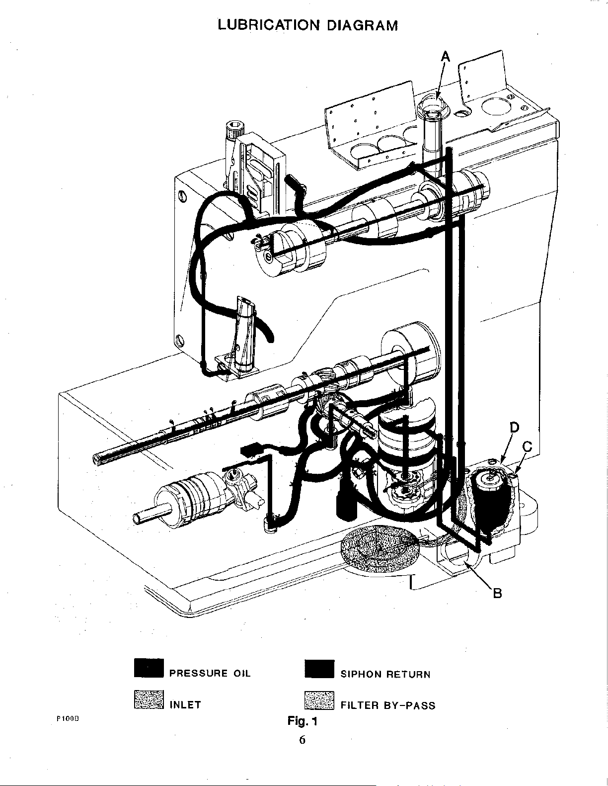
LUBRICATION DIAGRAM
•
P100B
PRESSURE
OIL
•
~TfM!~!f@
SIPHON
FILTER
Fig.1
6
RETURN
BY-PASS
Page 7
NEEDLES
Each needle has both a type and size number. Type number denotes the kind
fmish, and other details. Size number, stamped on the needle shank in metric, denotes largest diameter
blade, measured midway between shank and eye. Collectively, type and size number represent the complete
symbol, which is given on the label
TION.
The type numbers
in the machine style description. Other needles are available, but the ones indicated are those recommended
to produce the most satisfactory results. The type numbers
descriptions, and the sizes available are listed below:
NEEDLE TYPE
128 GAS
128 GBS
of
the needles recommended for each Style
Round shank, round point, short, double
groove, struck groove, ball eye, spotted,
chromium plated.
Round shank, round point, short, double
groove, struck groove, ball eye, spotted, ball
point, chromium plated.
of
all needles packaged and sold by UNION SPECIAL CORPORA-
of
machine covered by this catitlog are given
of
the recommended needles together with their
DESCRIPTION
of
shank, point, length, groove,
SIZES AVAILABLE
80/032, 90/036,
100/040, 110/044,
125/049, 140/054,
150/060, 170/067.
80/032, 90/036,
100/040, 10/044,
125/049, 140/054,
150/060.
of
192GLS
To have needle orders promptly and accurately filled, an empty package, a sample needle,
Size number should be forwarded.
Type 128 GBS, Size
Round shank, round point, extra short, double
groove, struck groove, ball eye, spotted
(plated) thin ball point, chromium.
Use description on label. A complete order would read
90/036".
55/022, 65/025,
70/027, 75/029,
80/032, 90/036.
or
the Type and
"1
000 needles,
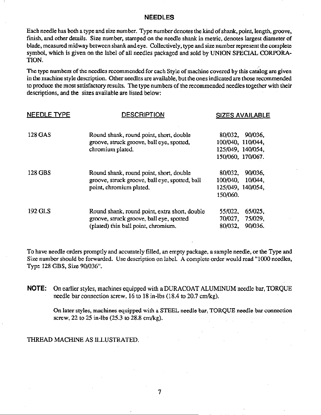
NOTE: On earlier styles, machines equipped with a DURACOAT ALUMINUM needle bar, TORQUE
needle bar connection screw, 16 to
On later styles, machines equipped with a STEEL needle bar, TORQUE needle bar connection
screw, 22 to 25 in-lbs (25.3 to 28.8 ern/kg).
TIIREAD MACHINE AS ILLUSTRATED.
18
in-lbs (18.4 to 20.7 ern/kg).
7
Page 8
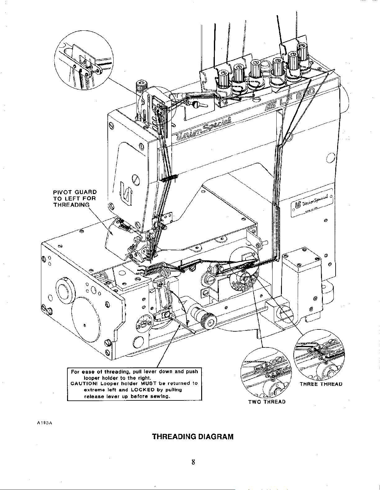
PIVOT
TO
LEFT FOR
GUARD
•
For
ease
looper
CAUTION!
extreme
release
of
threading,
holder
Looper
left
lever
to
the
holder
and
up
right.
MUST
LOCKED
before
·be
by
sewing.
returned
pulling
to
TWO
THREAD
A193A
THREADING DIAGRAM
8
Page 9
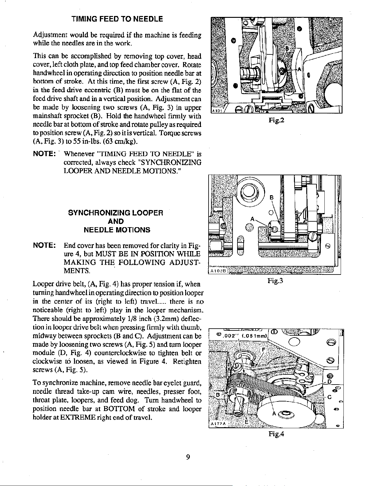
TIMING FEED TO NEEDLE
Adjustment would be required
while the needles are in the work.
This can be accomplished by removing top cover, head
cover, left cloth plate, and top feed chamber cover. Rotate
handwheel in operating direction to position needle bar at
bottom
in the feed drive eccentric (B) must be on the flat
feed drive shaft and in a vertical position. Adjustment can
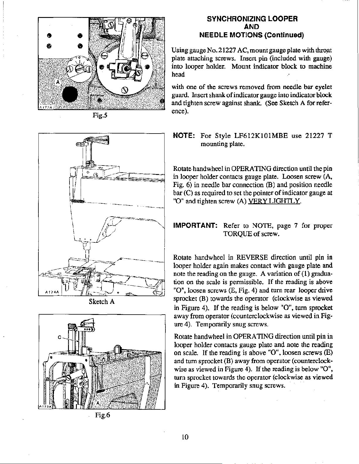
be made by loosening two screws (A, Fig. 3) in upper
mainshaft sprocket (B). Hold the handwheel
needle bar at bottom
to position screw (A, Fig. 2) so it is vertical. Torque screws
(A, Fig. 3) to 55 in-lbs. (63 em/kg).
NOTE:,
of
stroke. At this time, the first screw (A, Fig. 2)
of
stroke and rotate pulley as required
Whenever "TIMING FEED TO NEEDLE" is
corrected, always check
LOOPER
SYNCHRONIZING LOOPER
AND NEEDLE MOTIONS."
AND
NEEDLE
if
the machine is feeding
"SYNCHRONIZING
MOTIONS
of
the
fmnly with
Fig.2
NOTE:
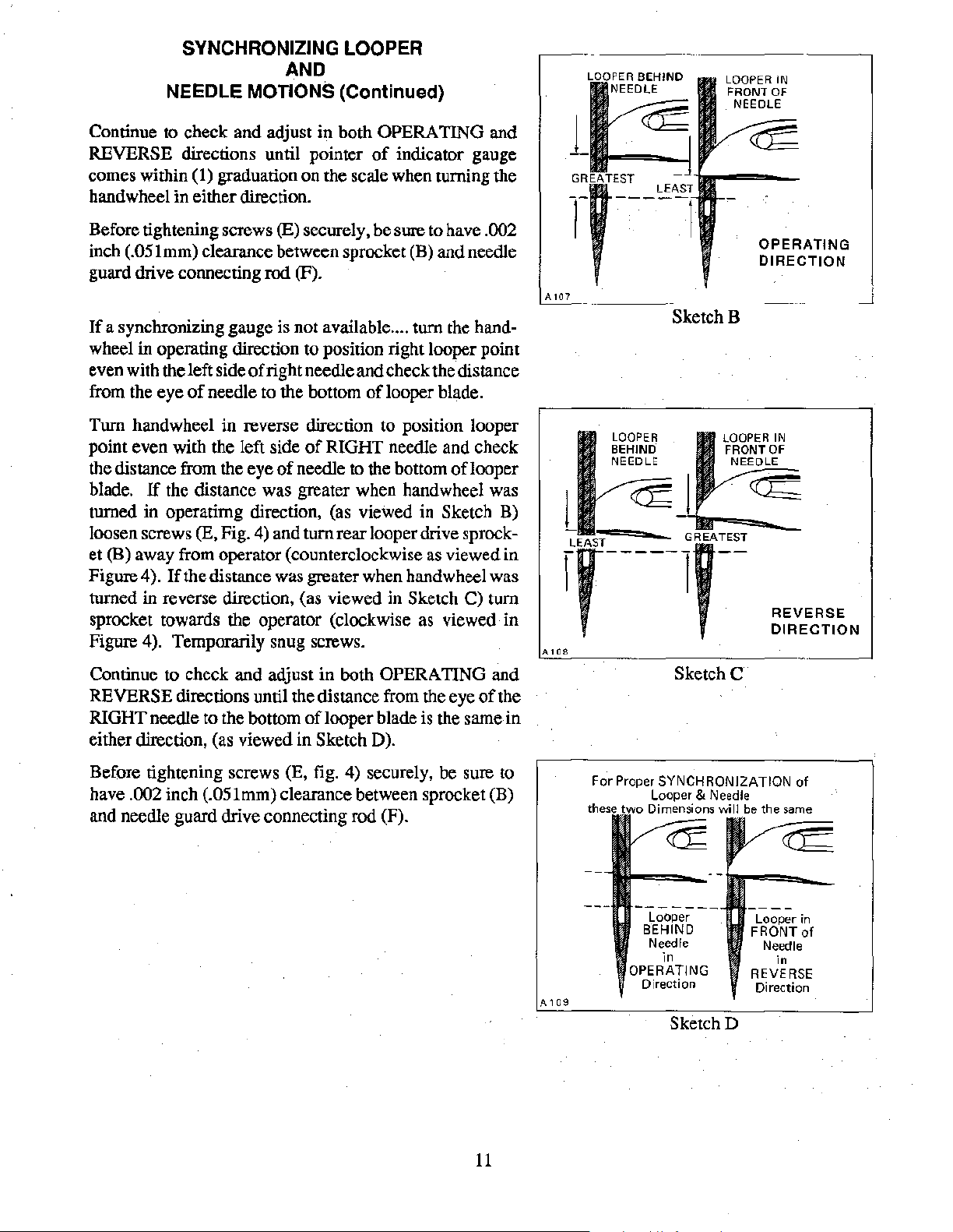
Looper drive belt, (A, Fig. 4) has proper tension if, when
turning hand wheel in operating direction
in the center
noticeable (right to left) play in the looper mechanism.
There should be approximately 1/8 inch (3.2mm) deflection in looper drive belt when pressing
midway between sprockets
made by loosening two screws (A, Fig. 5) and tum looper
module (D, Fig. 4) counterclockwise to tighten belt or
clockwise
screws (A, Fig.
To synchronize machine, remove needle bar eyelet guard,
needle thread take-up cam wire, needles, presser foot,
throat plate, loopers, and feed dog. Tum handwheel to
position needle bar at
holder at
End cover has been removed for clarity in Figure 4, but MUST BE IN POSITION WHILE
MAKING
MENTS.
of
to
loosen,
5).
EX1REME right end
THE
its (right to left) travel...
as
FOLLOWING
,
fmnly with thumb,
(B
and C). Adjustment can be
viewed in Figure
BOTTOM
of
of
stroke and looper
travel.
to
ADJUST-
position looper
..
there is no
4.
Retighten
Fig.3
9
Fig.4
Page 10
SYNCHRONIZING LOOPER
AND
NEEDLE MOTIONS (Continued)
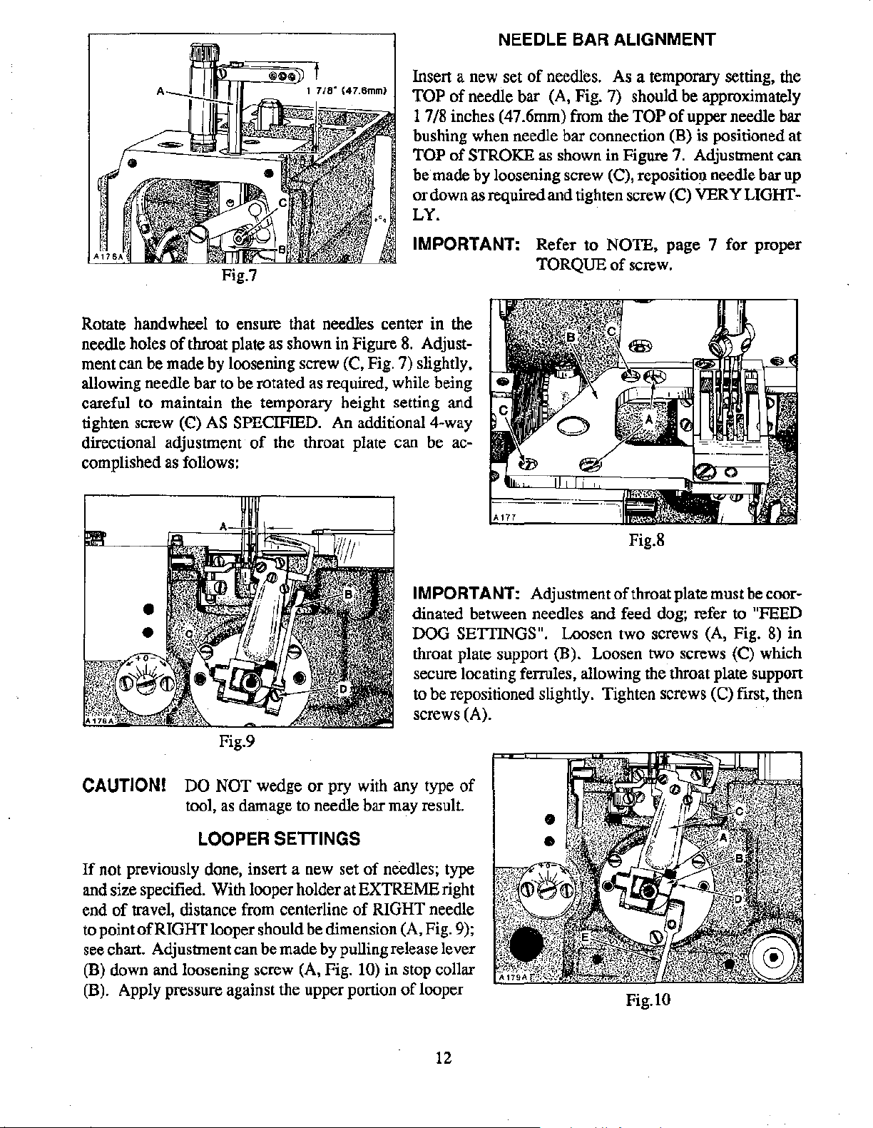
Using gauge No. 21227 AC, mount gauge plate with thro.at
plate attaching screws. Insen pin (included with gauge)
into looper holder. Mount indicator block to machine
head
Fig.S
with one
guard.
and tighten screw against shank.
ence).
NOTE:
Rotate hand wheel in
in looper holder contacts gauge plate. Loosen screw (A,
Fig.
bar
"0"
IMPORTANT: Refer to NOTE, page 7 for proper
of
the screws removed from needle bar eyelet
lnsen
6)
(C)
and tighten screw (A) VERY LIGH1L
shank
of
indicator gauge into indicator block
(See Sketch A for refer-
For
Style
mounting plate.
in needle bar connection (B) and position needle
as
required to set the pointer
LF612Kl01MBE
OPERATING direction until the pin
TORQUE
of
screw.
use
21227 T
of
indicator gauge at
Y.
Sketch A
Fig.6
Rotate handwheel in REVERSE direction until pin in
looper holder again makes contact with gauge plate and
of
note the reading on the gauge. A variation
tion on the scale is permissible.
"0",
loosen screws (E, Fig. 4) and tum rear looper drive
sprocket (B) towards the operator (clockwise as viewed
If
in Figure 4).
away from operator (counterclockwise as viewed in Figure 4). Temporarily snug screws.
Rotate handwheel in
looper holder contacts gauge plate and note the reading
on scale.
and turn sprocket (B) away from operator (counterclockwise
turn sprocket towards the operator (clockwise as viewed
in Figure 4). Temporarily snug screws.
If
as
viewed in Figure 4).
the reading is below
OPERATING direction until pin in
the reading is above
If
the reading is above
"0",
"0",
loosen screws (E)
If
the reading is below
(1) gradua-
tum sprocket
"0",
10
Page 11
SYNCHRONIZING LOOPER
AND
NEEDLE
MOTIONS (Continued)
LOOPER IN
FRONT
OF
NEEDLE
Continue to check and adjust in both OPERATING and
REVERSE directions until pointer
comes within (1) graduation on the scale when turning the
hand wheel in either direction.
Before tightening screws
inch (.051mm) clearance between sprocket (B) and needle
guard drive connecting
If
a synchronizing gauge is not available .... turn the hand-
wheel in operating direction to position right looper point
even with the left side
from the eye
Turn handwheel in reverse direction to position looper
point even with the left side
the distance from the eye
blade.
turned in operatirng direction, (as viewed in Sketch B)
loosen screws
et (B) away from operator (counterclockwise
Figure 4 ).
turned in reverse direction, (as viewed in Sketch
sprocket towards the operator (clockwise as viewed in
Figure 4). Temporarily snug screws.
Continue to check and adjust in both OPERATING and
REVERSE directions until the distance from the eye
RIGHT needle to the bottom
either direction, (as viewed in Sketch D).
of
needle to the bottom
If
the distance was greater when handwheel was
(E, Fig. 4) and turn rear looper drive sprock-
If
the distance was greater when hand wheel was
(E) securely, be sure to have .002
rod (F).
of
right needle and check the distance
of
of
needle to the bottom
of
of
indicator gauge
of
looper blade.
RIGHT needle and check
of
looper
as
viewed in
C) tum
of
the
looper blade is the same in
t[§
~:EATEST
r
A107
LOOPER
BEHIND
NEEDLE
A108
_j
OPERATING
DIRECTION
SketchB
GREATEST
REVERSE
DIRECTION
SketchC
Before tightening screws (E, fig. 4) securely, be sure to
have
.002 inch (.051mm) clearance between sprocket (B)
and needle guard drive connecting rod (F).
A
109
11
For Proper SYNCHRONIZATION
Looper & Needle
Dimensions
-------
Looper
BEHIND
Needle
in
OPERATING
Direction
SketchD
will
in
REVERSE
Direction
of
Page 12
NEEDLE BAR ALIGNMENT
Insert a new set
TOP
of
1 7/8 inches (47.6mm) from the
bushing when needle bar connection (B) is positioned at
TOP
of
be made by loosening screw (C), reposition needle bar up
or down as required and tighten screw
LY.
IMPORTANT: Refer to NOTE,
Rotate handwheel to ensure that needles center in the
needle holes
ment can be made by loosening screw (C, Fig. 7) slightly,
allowing needle bar to be rotated
careful to maintain the temporary height setting and
tighten screw (C)
directional adjustment
complished
of
throat plate as shown in Figure
as
required, while being
AS
SPECIFIED. An additional 4-way
of
the throat plate can be ac-
as
follows:
8.
Adjust-
of
needles. As a temporary setting, the
needle bar (A, Fig. 7) should be approximately
TOP
of
upper needle bar
STROKE as shown in Figure 7. Adjustment can
(C) VERY LIGHT-
page
7 for proper
TORQUE
of
screw.
IMPORTANT: Adjustmentofthroatplatemustbecoor-
dinated between needles and feed dog; refer to
DOG SETTINGS". Loosen two screws (A, Fig. 8)
throat plate support (B). Loosen two screws (C) which
secure locating ferrules, allowing the throat plate support
to be repositioned slightly. Tighten screws (C) first, then
screws (A).
Fig.9
CAUTION!
If
not previously done, insert a new set
and size
end
to point
see chart. Adjustment can be made by pulling release lever
(B) down and loosening screw (A, Fig.
(B). Apply pressure against the upper portion
specified. With looper holder at EXTREME right
of
travel, distance from centerline
of
DO
NOT wedge
tool, as damage to needle bar may result.
LOOPER SETTINGS
RIGHT looper should be dimension (A, Fig. 9);
or
pry with any type
of
needles; type
of
RIGHT needle
10) in stop collar
of
of
looper
Fig.8
"FEED
in
Fig.lO
12
Page 13
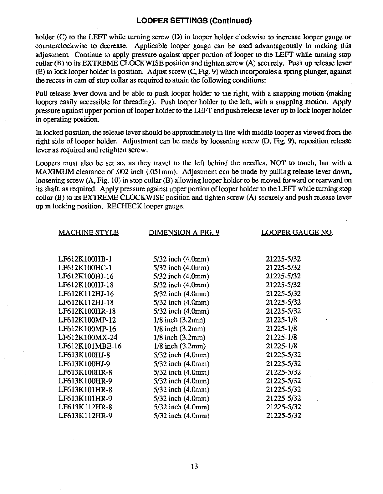
LOOPER SETTINGS (Continued)
holder (C) to the
counterclockwise to decrease. Applicable looper gauge can be used advantageously in making this
adjustment Continue to apply pressure against upper portion
collar (B) to its EXTREME CLOCKWISE position and tighten screw (A) securely. Push up release lever
(E)
to
lock looper holder in position. Adjust screw (C, Fig. 9) which incorporates a spring plunger, against
the recess in cam
Pull release lever down and be able to push looper holder to the right, with a snapping motion (making
loopers easily accessible for threading).
pressure against upper portion
in operating position.
In locked position, the release lever should be approximately in line with middle looper as viewed from the
right side
lever as required and retighten screw.
Loopers must also be set so, as they travel to the left behind the needles,
MAXIMUM clearance
loosening screw (A, Fig.
its shaft,
collar (B) to its EXTREME
up in locking position. RECHECK looper gauge.
of
as
required. Apply pressure against upper portion
LEFf
of
looper holder. Adjustment can be made by loosening screw (D, Fig. 9), reposition release
while turning screw (D) in looper holder clockwise to increase looper gauge
of
looper to the
stop collar as required to attain the following conditions:
Push looper holder
of
looper holder to the
of
.002 inch (.051mm). Adjustment can be made by pulling release lever down,
10) in stop collar (B) allowing looper holder to be moved forward
CLOCKWISE position and tighten screw (A) securely and push release lever
LEFf
to
the left, with a snapping motion. Apply
and push release lever up to lock looper holder
of
looper holder to the
LEFf
NOT to touch, but with a
while turning stop
or
LEFf
while turning stop
or
rearward on
MACHINE
LF612K100HB-1
LF612KlOOHC-1
LF612K100HJ-16
LF612K100HJ-18
LF612K112HJ-16
LF612K112HJ-18
LF612K100HR-18
LF612K100MP-12
LF612K100MP-16
LF612K100MX-24
LF612K101MBE-16
LF613K100HJ-8
LF613K100HJ-9
LF613K100HR-8
LF613K100HR-9
LF613K101HR-8
LF613K101HR-9
LF613K112HR-8
LF613Kll2HR-9
STYLE
DIMENSION A FIG. 9
5/32 inch
5/32 inch (4.0mm)
5/32 inch (4.0mm)
5/32 inch (4.0mm)
5/32 inch (4.0mm)
5/32 inch (4.0mm)
5/32 inch (4.0mm)
1/8 inch (3.2mm)
1/8 inch (3.2mm)
1/8 inch (3.2mm)
1/8 inch (3.2mm)
5/32 inch
5/32 inch (4.0mm)
5/32 inch (4.0mm)
5/32 inch (4.0mm)
5/32 inch (4.0mm)
5/32 inch (4.0mm)
5/32 inch (4.0mm)
5/32 inch (4.0mm)
(4.0mm)
(4.0mm)
LOOPER GAUGE NO.
21225-5/32
21225-5/32
21225-5/32
21225-5/32
21225-5/32
21225-5/32
21225-5/32
21225-1/8
21225-1/8
21225-1/8
21225-1/8
21225-5/32
21225-5/32
21225-5/32
21225-5/32
21225-5/32
21225-5/32
21225-5/32
21225-5/32
13
Page 14
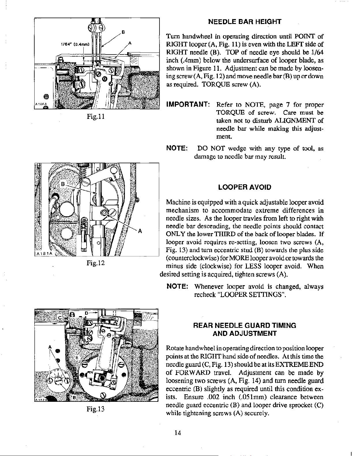
NEEDLE BAR HEIGHT
Fig.ll
Fig.12
Turn handwheel in operating direction until POINT
RIGHT looper (A, Fig. 11) is even with the LEFT side
RIGHT needle (B). TOP
inch (.4mm) below the undersurface
shown in Figure
11.
ing screw (A, Fig. 12) and move needle bar
as
required. TORQUE screw (A).
IMPORTANT: Refer to NOTE, page 7 for proper
TORQUE
of
needle eye should be
of
looper blade, as
Adjustment can be made by loosen-
(B) up or down
of
screw. Care must be
taken not to disturb ALIGNMENT
needle bar while making this adjustment.
NOTE: DO NOT wedge with any type
of
tool,
damage to needle bar may result.
LOOPER AVOID
Machine is equipped with a quick adjustable looper avoid
mechanism to accommodate extreme differences in
needle sizes.
As
the looper travles from left to right with
needle bar descending, the needle points should contact
ONLY the lower THIRD
of
the back
of
looper blades.
looper avoid requires re-setting, loosen two screws (A,
Fig.
13) and turn eccentric stud (B) towards the plus side
(counterclockwise) for
MORE looper avoid or towards the
minus side (clockwise) for LESS looper avoid. When
desired setting is acquired, tighten screws (A).
of
of
l/64
of
as
If
NOTE: Whenever looper avoid is changed, always
recheck
REAR NEEDLE GUARD TIMING
Rotate hand wheel in operating direction to position looper
points at the RIGHT hand side
needle guard (C, Fig.
of
FORWARD travel. Adjustment can be made by
loosening two screws (A, Fig. 14) and turn needle guard
Fig.13
eccentric
ists. Ensure
needle guard eccentric
while tightening screws (A) securely.
(B) slightly as required until this condition ex-
.002 inch (.05lmm) clearance between
14
"LOOPER SETTINGS".
AND ADJUSTMENT
of
needles. At this time the
13) should be at its EXTREME END
(B) and looper drive sprocket (C)
Page 15
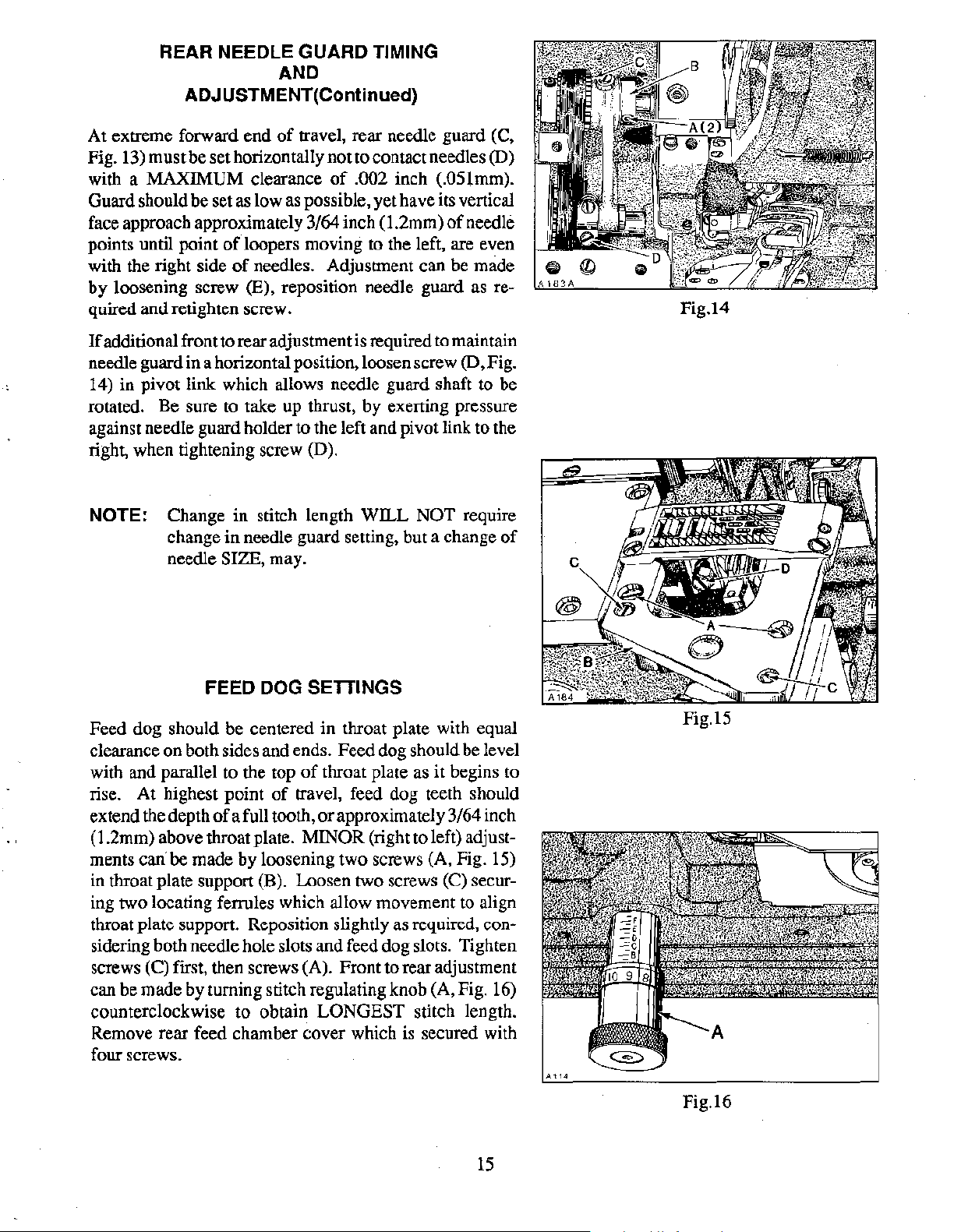
REAR NEEDLE GUARD TIMING
AND
ADJUSTMENT(Continued)
of
At extreme forward end
Fig. 13) must be set horizontally not to contact needles
with a MAXIMUM clearance
Guard should be set as low as possible, yet have its vertical
face approach approximately
points until point
with the right side
by loosening screw
quired and retighten screw.
If
additional front to rear adjustment is required to maintain
needle guard in a horizontal position, loosen screw
14) in pivot link which allows needle guard shaft to be
rotated. Be sure
against needle guard holder to the left and pivot link to the
right, when tightening screw (D).
of
loopers moving to the left, are even
of
(E), reposition needle guard
to
take up thrust, by exerting pressure
travel, rear needle guard (C,
(D)
of
.002 inch (.05lmm).
3/64 inch (1.2mm)
needles. Adjustment can be made
of
needle
as
(D, Fig.
re-
Fig.14
NOTE: Change in stitch length WILL NOT require
change in needle guard setting, but a change
needle SIZE, may.
FEED
Feed dog should be centered in throat plate with equal
clearance on both sides and ends. Feed dog should be level
with and parallel to the top
rise. At highest point
extend the depth
(1.2mm) above throat plate.
ments
in throat plate support (B). Loosen two screws
ing two locating ferrules which allow movement to align
throat plate support. Reposition slightly
sidering both needle hole slots and feed dog slots. Tighten
screws
can be made by turning stitch regulating knob (A, Fig. 16)
counterclockwise to obtain LONGEST stitch length.
Remove rear feed chamber cover which is secured with
four screws.
can' be made by loosening two screws (A, Fig. 15)
(C) first, then screws (A). Front to rear adjustment
of
DOG SETTINGS
of
throat plate
of
travel, feed dog teeth should
a full tooth,
or
approximately 3/64 inch
MINOR (right to left) adjust-
as
it begins to
(C) secur-
as
required, con-
of
Fig.15
15
Fig.16
Page 16
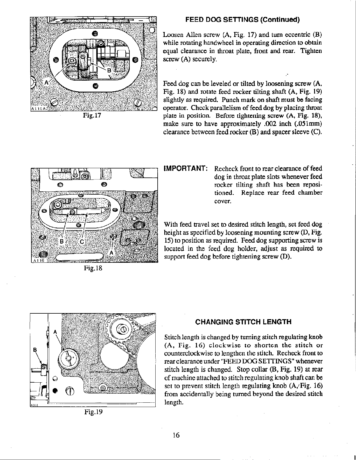
FEED DOG SETTINGS (Continued)
Loosen Allen screw (A, Fig. 17) and turn eccentric (B)
while rotating handwheel in operating direction to obtain
equal clearance in throat plate, front and rear. Tighten
screw (A) securely.
Feed dog can be leveled or tilted by loosening screw (A,
18)
Fig.
slightly
operator. Check parallelism
plate in position. Before tightening screw (A, Fig. 18),
make sure to have approximately
clearance between feed rocker
and rotate feed rocker tilting shaft (A, Fig. 19)
as
required. Punch mark on shaft must be facing
of
feed dog by placing throat
.002 inch (.051mm)
(B) and spacer sleeve (C).
Fig.18
Fig.19
IMPORTANT: Recheck front to rear clearance
dog in throat plate slots whenever feed
rocker tilting shaft has been repositioned. Replace rear feed chamber
cover.
With feed travel set to desired stitch length, set feed dog
height as specified by loosening mounting screw
15)
to position
located in the feed dog holder, adjust as required to
support feed dog before tightening screw (D).
Stitch length is changed by turning stitch regulating knob
(A,
Fig.
counterclockwise to lengthen the stitch. Recheck front to
rear clearance under
stitch length
of
machine attached to stitch regulating knob shaft can be
set to prevent stitch length regulating knob
accidentally being turned beyond the desired stitch
from
length.
as
required. Feed dog supporting screw
CHANGING STITCH LENGTH
16)
clockwise
"FEED DOG SETTINGS" whenever
is
changed. Stop collar (B, Fig. 19) at rear
to
shorten
the
of
feed
(D, Fig.
is
stitch
(A,' Fig. 16)
or
16
Page 17
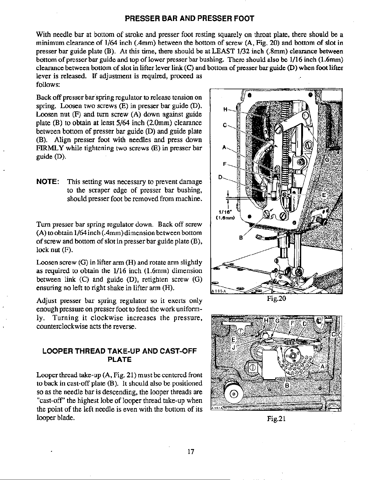
PRESSER BAR AND PRESSER FOOT
With needle bar at bottom
minimum clearance
of
of
stroke and presser foot resting squarely
1/64 inch (.4mm) between the bottom
presser bar guide plate (B). At this time, there should be at
bottom
clearance between bottom
of
presser bar guide and top
of
of
lower presser bar bushing. There should also be 1/16 inch (1.6mm)
slot in lifter lever link (C) and bottom
lever is released. 1f adjustment is required, proceed as
follows:
Back
off
presser bar spring regulator to release tension
on
spring. Loosen two screws (E) in presser bar guide (D).
Loosen nut (F) and turn screw (A) down against guide
(B)
plate
between bottom
to obtain at least 5/64 inch (2.0mm) clearance
of
presser bar guide (D) and guide plate
(B). Align presser foot with needles and press down
FIRMLY while tightening two screws
(E) in presser bar
guide (D).
NOTE: This setting was necessary to prevent damage
to the scraper edge
of
presser bar bushing,
should presser foot be removed from machine.
on
throat plate, there should
of
screw (A, Fig. 20) and bottom
LEAST
1132
inch (.8mm) clearance between
of
presser bar guide
of
(D)
when foot lifter
be
a
slot in
off
Turn presser bar spring regulator down. Back
screw
(A) to obtain 1/64 inch (.4mm) dimension between bottom
of
screw and bottom
of
slot in presser bar guide plate (B),
lock nut (F).
(H)
Loosen screw (G) in lifter arm
and rotate arm slightly
as required to obtain the 1/16 inch (1.6mm) dimension
between link (C) and guide (D), retighten screw (G)
ensuring no left to right shake in lifter arm (H).
Adjust presser bar spring regulator so
it
exerts only
enough pressure on presser foot to feed the work uniformly.
Turning
it
clockwise
increases
the
pressure,
counterclockwise acts the reverse.
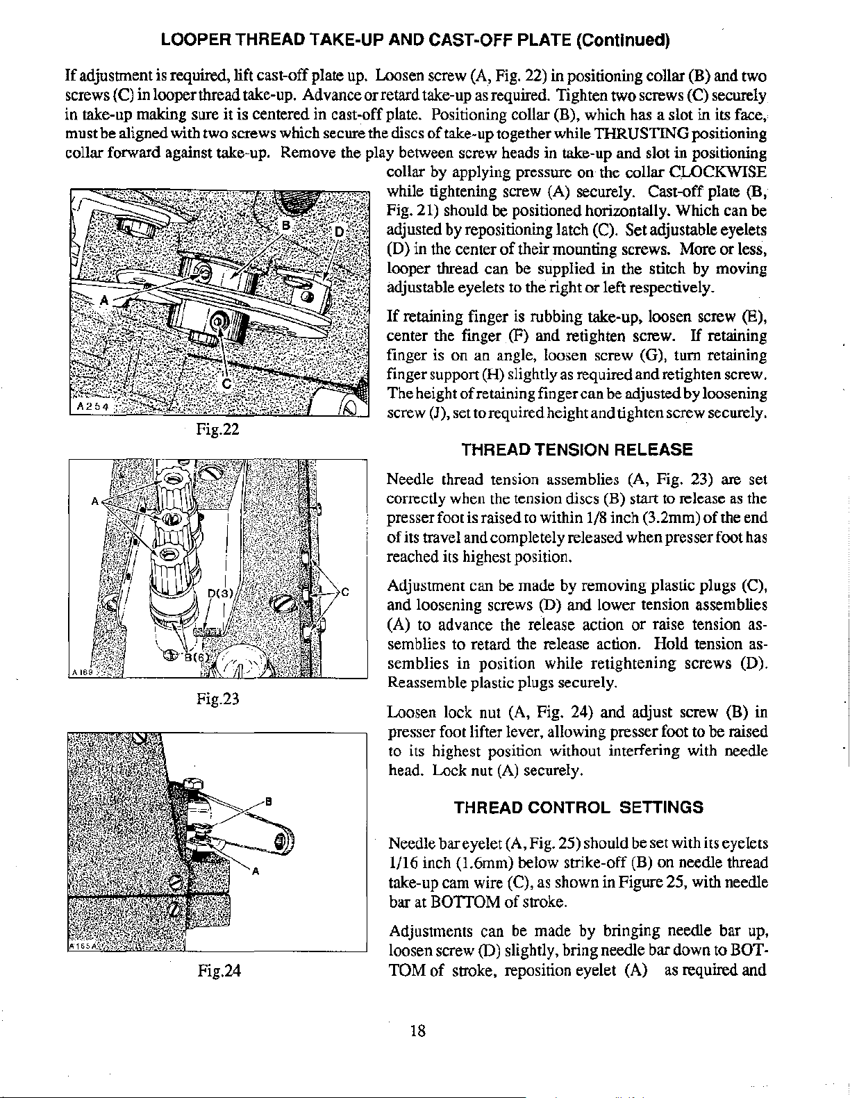
LOOPER THREAD TAKE-UP AND CAST-OFF
PLATE
Looper thread take-up (A, Fig. 21) must be centered front
to back in cast-off plate (B).
It
should also be positioned
so as the needle bar is descending, the looper threads are
"cast-off' the highest lobe
the point
of
the left needle is even with the bottom
of
looper thread take-up when
of
its
looper blade.
1/16"
(1.6mml
Fig.21
17
Page 18
LOOPER THREAD TAKE-UP AND CAST-OFF PLATE (Continued)
If
adjustment is required, lift cast-off plate up. Loosen screw (A, Fig. 22) in positioning collar (B) and two
screws (C) in looper thread take-up. Advance or retard take-up as required. Tighten two screws (C) securely
in take-up making sure it is centered in
cast~off
must be aligned with two screws which secure the discs
plate. Positioning collar (B), which has a slot in its face,
of
take-up together while THRUSTING positioning
collar forward against take-up. Remove the play between screw heads in take-up and slot in positioning
collar by applying pressure on the collar
CLOCKWISE
while tightening screw (A) securely. Cast-off plate (B,
Fig. 21) should be positioned horizontally. Which can be
adjusted by repositioning latch (C).
(D) in the center
of
their mounting screws. More or less,
Set adjustable eyelets
looper thread can be supplied in the stitch by moving
adjustable eyelets to the right or left respectively.
If
retaining finger is rubbing take-up, loosen screw (E),
center the fmger (F) and retighten screw.
If
retaining
finger is on an angle, loosen screw (G), turn retaining
finger support
The height
screw
(J), set to required height and tighten screw securely.
(H) slightly
of
retaining finger can be adjusted by loosening
as
required and retighten screw.
Fig.22
THREAD
TENSION RELEASE
Fig.23
Needle thread tension assemblies (A, Fig. 23) are set
as
correctly when the tension discs (B) start to release
presser foot is raised to within 1/8 inch (3.2mm)
of
its travel and completely released when presser foot has
of
the
the end
reached its highest position.
Adjustment can be made by removing plastic plugs (C),
and loosening screws
(A) to advance the release action
(D) and lower tension assemblies
or
raise tension as-
semblies to retard the release action. Hold tension as-
semblies in position while retightening screws (D).
Reassemble plastic plugs securely.
Loosen lock nut (A, Fig. 24) and adjust screw (B) in
presser foot lifter lever, allowing presser foot to be raised
to its highest position without interfering with needle
head. Lock nut
THREAD
(A)
securely.
CONTROL SETTINGS
Needle bar eyelet (A, Fig. 25) should be set with its eyelets
1/16 inch (1.6mm) below strike-off (B) on needle thread
take-up cam wire (C), as shown in Figure 25, with needle
bar at BOTTOM
of
stroke.
Adjustments can be made by bringing needle bar up,
loosen screw (D) slightly, bring needle bar down to
of
Fig.24
TOM
stroke, reposition eyelet (A) as required and
18
BOT-
Page 19
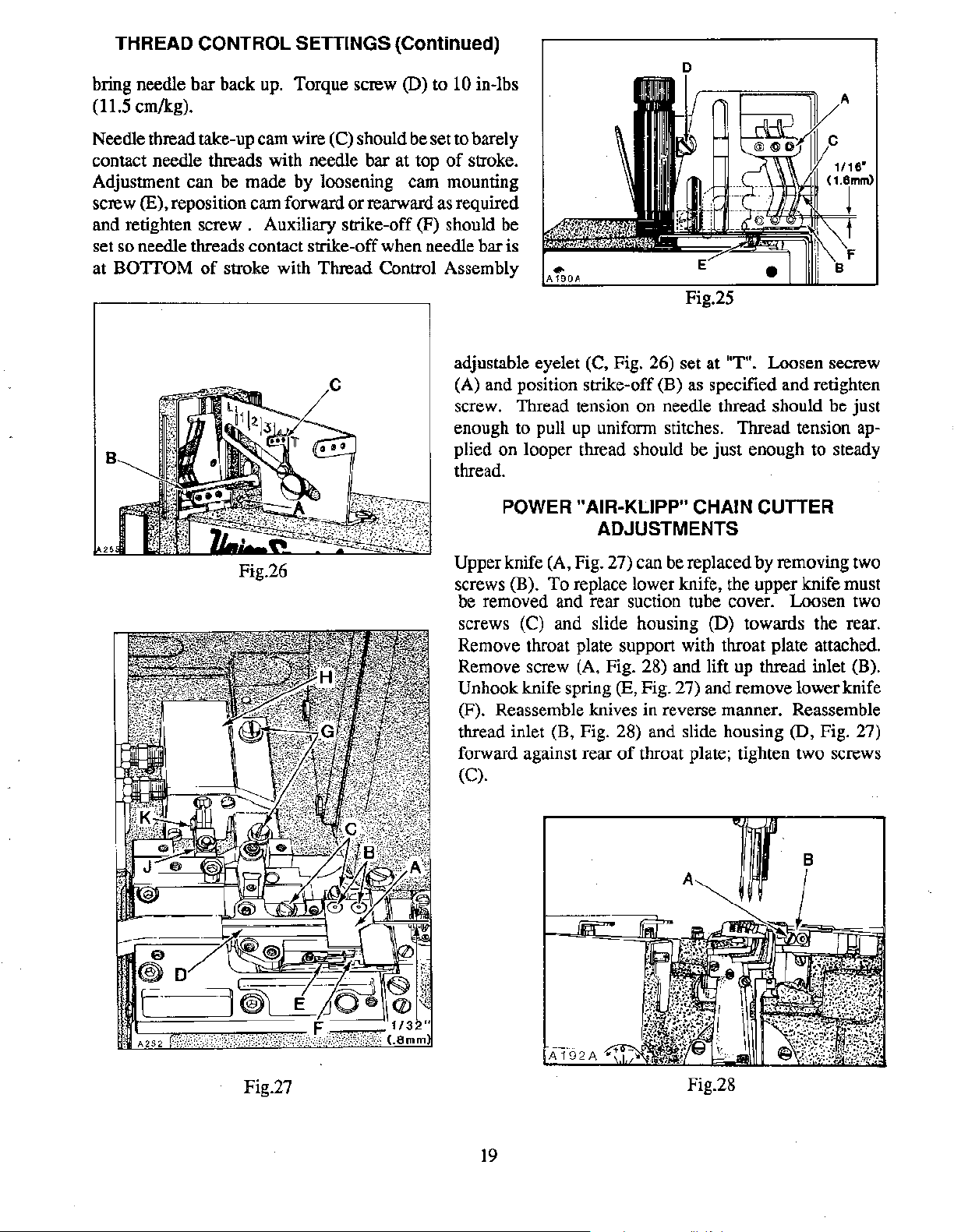
THREAD CONTROL SETTINGS (Continued)
bring needle bar back up. Torque screw (D) to 10 in-lbs
(11.5 em/kg).
Needle thread take-up cam wire
contact needle threads with needle bar at top
(C) should be set to barely
of
stroke.
Adjustment can be made by loosening cam mounting
screw
and retighten screw . Auxiliary strike-off
(E), reposition cam forward
or
rearward as required
(F) should be
set so needle threads contact strike-off when needle bar is
at
BOTTOM
of
stroke with Thread Control Assembly
adjustable eyelet (C, Fig. 26) set at
(A) and position strike-off (B) as specified and retighten
screw. Thread tension on needle thread should be just
enough to pull
plied on looper thread should be just enough to steady
thread.
POWER "AIR-KLIPP" CHAIN CUTTER
Fig.26
Upper knife (A, Fig. 27) can be replaced by removing two
screws
be removed and rear suction tube cover. Loosen two
screws (C) and slide housing (D) towards the rear.
Remove throat plate support with throat plate attached.
Remove screw (A, Fig. 28) and lift up thread inlet (B).
Unhook knife spring (E, Fig. 27) and remove lower knife
(F). Reassemble knives in reverse manner. Reassemble
thread inlet (B, Fig. 28) and slide housing
forward against rear
(C).
(B).
"T". Loosen secrew
up
uniform stitches. Thread tension ap-
ADJUSTMENTS
To
replace lower knife, the upper knife must
(D, Fig. 27)
of
throat plate; tighten two screws
Fig.27
19
Fig.28
Page 20
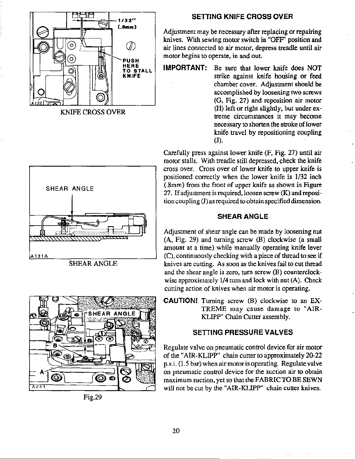
A130
0
SHEAR
1/32"
(.8mm)
PUSH
HERE
TO
KNIFE
KNIFE CROSS OVER
ANGLE
(//)
STALL
SETIING
Adjustment may be necessary after replacing
knives. With sewing motor switch in
KNIFE CROSS OVER
or
"OFF" position and
repairing
air lines connected to air motor, depress treadle until air
motor begins to operate, in and out.
IMPORTANT: Be sure that lower knife does NOT
strike against knife housing
chamber cover. Adjustment should
or
feed
be
accomplished by loosening two screws
(G, Fig. 27) and reposition air motor
(H) left
treme circumstances
necessary to shorten the stroke
or
right slightly, but under ex-
it
may become
oflower
knife travel by repositioning coupling
(J).
Carefully press against lower knife (F, Fig. 27) until air
motor stalls. With treadle still depressed, check the knife
cross over. Cross over
of
lower knife to upper knife is
positioned correctly when the lower knife is 1/32 inch
(.8mm) from the front
27.
If
adjustment is required, loosen screw
tion coupling (J)
as
of
upper knife as shown in Figure
(K)
and reposi-
required to obtain specified dimension.
A
131A
SHEAR ANGLE
Fig.29
SHEAR ANGLE
Adjustment
of
shear angle can be made by loosening nut
(A, Fig. 29) and turning screw (B) clockwise (a small
amount at a time) while manually operating knife lever
(C), continuously checking with a piece
of
thread to see
if
knives are cutting. As soon as the knives fail to cut thread
and the shear angle is zero, turn screw (B)
counterclockwise approximately 1/4 turn and lock with nut (A). Check
cutting action
of
knives when air motor is operating.
CAUTION! Turning screw (B) clockwise to an EX-
TREME
KLIPP"
SETIING
may
cause
damage
Chain Cutter assembly.
PRESSURE VALVES
to
"AIR-
Regulate valve on pneumatic control device for air motor
of
the "AIR-KLIPP" chain cutter to approximately 20-22
p.s.i.
(1.5 bar) when air motor is operating. Regulate valve
on pneumatic control device for the suction air to obtain
maximum suction, yet so that the FABRIC
TO
BE SEWN
will not be cut by the "AIR-KLIPP" chain cutter knives.
20
Page 21
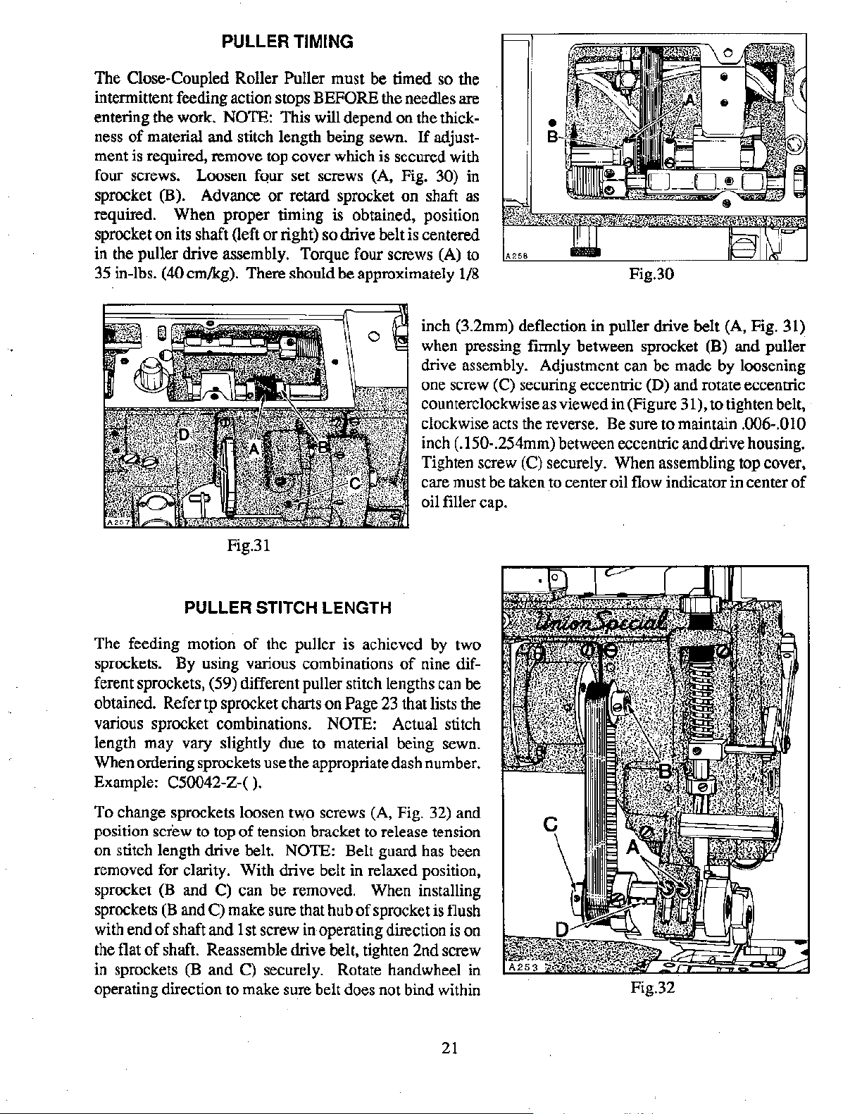
PULLER TIMING
The Close-Coupled Roller Puller must be timed
intermittent feeding action stops
entering the work.
ness
of
material and stitch length being sewn.
NOTE: This will depend on the thick-
BEFORE the needles are
If
so
the
adjustment is required, remove top cover which is secured with
four screws. Loosen four set screws (A, Fig.
sprocket
(B). Advance
or
retard sprocket on shaft as
30) in
required. When proper timing is obtained, position
sprocket
in the puller drive assembly. Torque four screws (A)
35 in-lbs. (40 em/kg). There should be approximately
on
its shaft (left
or
right) so drive belt is centered
to
1/8
inch (3.2mm) deflection in puller drive belt (A, Fig. 31)
when pressing
drive assembly. Adjustment can be made by loosening
one screw (C) securing eccentric
counterclockwise as viewed in (Figure 31),
clockwise acts the reverse. Be sure to maintain
inch (.150-.254mm) between eccentric and drive housing.
Tighten screw (C) securely. When assembling top cover,
care must be taken to center oil flow indicator in center
oil filler cap.
Fig.30
firmly between sprocket (B) and puller
(D)
and rotate eccentric
to tighten belt,
.006-.010
of
Fig.31
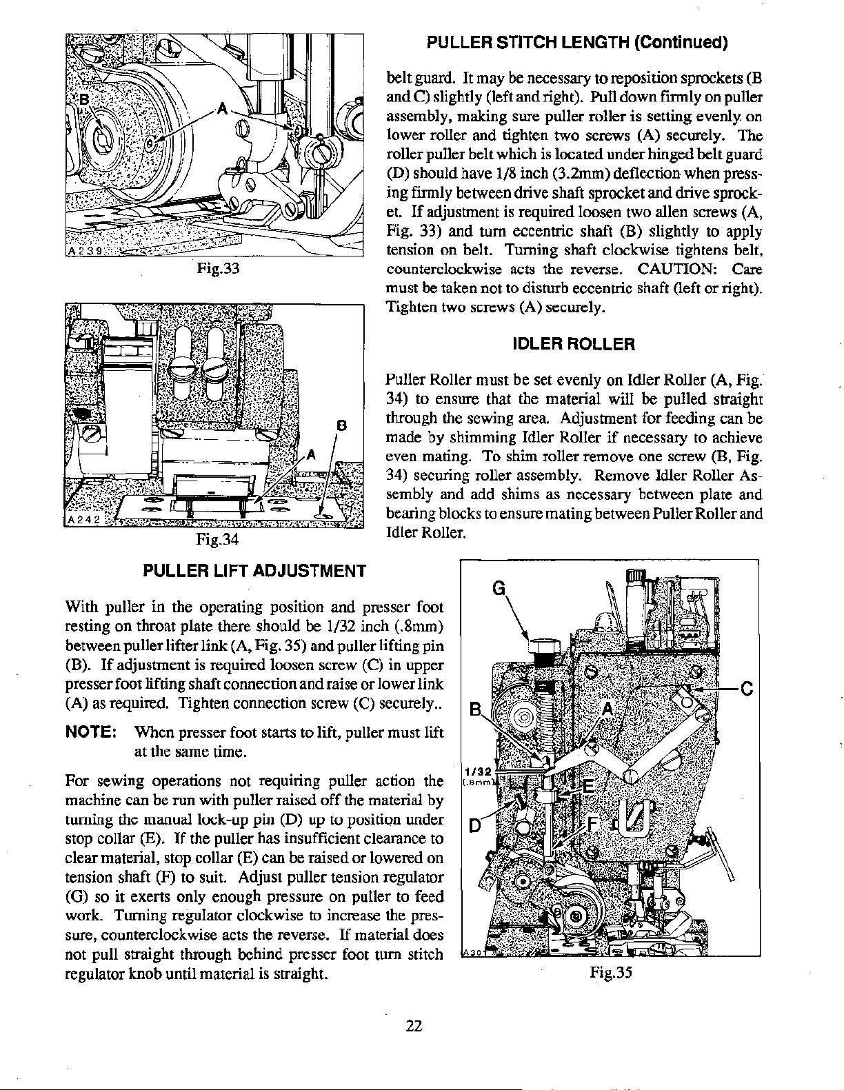
PULLER STITCH LENGTH
The feeding motion
sprockets. By using various combinations
of
the puller is achieved by two
of
nine different sprockets, (59) different puller stitch lengths can be
obtained. Refer
tp sprocket charts on Page
various sprocket combinations.
NOTE: Actual stitch
23
that lists the
length may vary slightly due to material being sewn.
When ordering sprockets use the appropriate dash number.
Example:
C50042-Z-(
).
To change sprockets loosen two screws (A, Fig. 32) and
position
screw to top
on stitch length drive belt.
of
tension bracket to release tension
NOTE: Belt guard has been
removed for clarity. With drive belt in relaxed position,
sprocket (B and
sprockets
with end
the flat
(B
of
of
shaft. Reassemble drive belt, tighten 2nd screw
in sprockets
C) can be removed. When installing
and C) make sure that hub
shaft and 1st screw
(B
and C) securely. Rotate handwheel in
in
of
sprocket is flush
operating direction is on
operating direction to make sure belt does not bind within
Fig.32
21
Page 22
PULLER
STITCH LENGTH (Continued)
Fig.34
belt guard. It may be necessary
and C) slightly (left and right). Pull down
assembly, making sure puller roller
lower roller and tighten two screws (A) securely. The
roller puller belt which is located under hinged belt guard
(D) should have
ing
fmnly
If
adjustment is required loosen two allen screws (A,
et.
Fig. 33) and
tension
counterclockwise acts the reverse.
must be taken not
Tighten two screws (A) securely.
on
1/8
inch (3.2mm) deflection when press-
between drive shaft sprocket and drive sprock-
tum
eccentric shaft (B) slightly to apply
belt. Turning shaft clockwise tightens belt,
to
disturb eccentric shaft (left
to
reposition sprockets (B
firmly
is
setting evenly on
CAUTION: Care
on
or
right).
puller
IDLER ROLLER
Puller Roller must
34) to ensure that the material will
through the sewing area. Adjustment for feeding can be
made by shimming Idler Roller
even mating.
34) securing roller assembly. Remove Idler Roller Assembly and add shims as necessary between plate and
bearing blocks to ensure mating between Puller Roller and
Idler Roller.
be
set evenly
To
shim roller remove
on
Idler Roller (A, Fig.
be
pulled straight
if
necessary to achieve
one
screw (B, Fig.
PULLER LIFT ADJUSTMENT
With puller in the operating position and presser foot
on
resting
between puller lifter link (A, Fig. 35) and puller lifting
(B).
presser foot lifting shaft connection
(A) as required. Tighten connection screw
NOTE:
For
machine can
turning the manual lock-up
stop collar
clear material, stop collar
tension shaft (F)
(G) so it exerts only enough pressure
work. Turning regulator clockwise to increase the pressure, counterclockwise acts the reverse.
not pull straight through behind presser foot
regulator knob until material is straight.
throat plate there should
If
adjustment
When
at
the same time.
sewing operations not requiring puller action the
be
(E).
is
required loosen screw (C) in upper
presser foot starts to lift, puller must lift
run
with puller raised
pin
If
the puller has insufficient clearance to
(E) can be raised
to
suit. Adjust puller tension regulator
(D)
be
1/32 inch (.8mm)
and
raise
or
lower link
(C) securely
off
the material by
up
to position under
or
lowered
on
puller to feed
If
material does
tum
pin
..
on
stitch
Fig.35
22
Page 23

PULLER SPROCKETS COMBINATIONS
This chart shows the stitch length produced by available sprocket combinations. Sprockets furnished
the machines produces approximately 9.2 S.P.I.
appropriate dash number when ordering sprockets-C50042-Z-(
r.<
=
IXl
~
~
z
14.69
-18
-17,
-16,
-15,
SPI
(1.73rnrn) (1.90rnrn)
13.87
SPI
(1.83rnrn)
13.06
SPI
(1.94rnrn)
Roller
13.37
SPI
12.25
(2.07rnrn)
12.62
(2.01rnrn) (2.20rnrn) (2.38rnrn) (2.56rnrn) (2.75rnrn)
11.88
(2.13rnm) (2.53rnrn) (2.53rnrn)
11.14
(2.28rnrn)
11.56
SPI
SPI
10.89
SPI 10.21 SPI
(2.49rnrn)
Puller
NUMBER
11.30
SPI
(2.25rnrn) (2.42rnrn) (2.59rnrn)
SPI
10.67
SPI
10.05
9.42
(2.70rnrn) (2.90rnrn)
If
a different length
Sprocket
OF
STITCHES PER INCH
SPI
SPI 9.91 SPI
SPI
SPI 8.75 SPI
Variations
10.50
SPI
9.34
SPI 8.71 SPI
(2.72rnrn)
).
9.80
SPI
9.25
SPI 8.67 SPI
(2.92rnrn)
8.16
SPI
(3.11rnrn)
is
required, refer to the chart for
9.18
SPI
8.65 SPI
(2. 77rnrn) (2. 94rnrn)
8.16
SPI 7.71 SPI
(2.93rnrn) (3.11rnrn)
8.16
SPI 7.69 SPI 7.26 SPI
(3.11rnrn)
7.65 SPI 7.21 SPI
(3.32rnrn) (3.52rnrn) (3.73rnrn)
(3.30rnrn) (3.50rnrn)
(3.30rnrn)
6.80
SPI
~
<
~
r.<
""
~
u
0
~
=
"'
z
r.<
..
-
Q
=
-14,
-13,
-12,
-11,
9.52
(2.67rnrn) (2.89rnrn) (3.11rnrn) (3.33rnrn) (3.56rnrn)
8.76 SPI
SPI
8.16
(3.11rnrn) (3.35 rnrn) (3.59rnrn) (3.83rnrn)
8.16 SPI 7.62
SPI 7.59 SPI 7.08
7.00
SPI
6.53
(3.63rnrn)
(3.89rnrn)
5.98
(4.24rnrn) (4.53rnrn) (4.81rnrn) (5.09rnrn)
SPI
SPI
SPI
SPI 5.61
7.14 SPI
6.63
6.12
(4.15rnrn) (4.41rnm) (4.67rnrn)
6.72
SPI 6.35
(3.78rnrn)
SPI 6.25 SPI
(4.07rnrn) (4.31rnrn)
SPI
5.76
SPI
5.28
SPI
SPI
SPI
(4.00rnrn)
5.90
SPI
5.44
SPI
4.99
SPI
in
-10,
C50042-Z-10,
A304
-11,
-12, -13,
DRIVE
SPROCKET
-14,
PART
-15,
NUMBER
5.10
SPI
4.81
SPI
4.54
SPI
(4.98rnrn) (5.28rnrn) (5.60rnrn)
-16, -17,
-18
23
Page 24

GENERAL
PREVENTIVE
MAINTENANCE
SCHEDULE
TASK
LF600
Check oil level (sight gauge)
· oil level between
Check pump operation
(oil flow indicator-top
Clean lint and
from
machine
Check that
and
shields
place and being used
Change oil-filter
(housed-on machine
bottom
Change oil (oil
which conforms to
U.S.C.
be used)
Clean lint and
from
cover)
spec
suction screen
(inside bottom cover)
red
dirt
all guards
are
in
175
must
dirt
lines.
of
ann)
AFTER EVERY EVERY EVERY
DAILY FIRST MONTH -3-
MONTH MONTHS
LF600
LF600
LF600
LF600
LF600
LF600
LF600
YEARLY
-6-
MONTHS
LF600
LF600
Check
tension
internal timing belts
Inspect clutch/
position motor,
V-belt,
Check clutch motor
clutch/hrake
adjustment
Clean lint
clutch/positioner
motor
air
Check needles
bent, blunt, sharp
or worn eye or groove
NOTE: SCHEDUllNG IS BASED ON NORMAL WORKING CONDffiONS FREQUENCY OF TASKS DEPENDS
ON MAClllNE DUTY CYCLE
DETERMINED BY PLANT MANAGEMENT
tension
from
passages
on
and
wear
LF600
TIME
LF600
LF600
LF600
AND
PERSONNEL RESPONSIBLE TO PERFORM TASK
LF600
LF600
LF600
24
Page 25

p
191
EXPLODED VIEWS
AND
DESCRIPTION OF PARTS
25
Page 26

16
21
44
50
TORQUE TO
16-18
in.
(18-21
lbs
ern/kg)
9445
51
P186A
26
74
Page 27

OIL PUMP, PAN AND LUBRICATION PARTS
Ref.
Part
No. No.
1 50393
CB
2 22653 B-36
3
50393
CD
4 22571 F
5
50394X
6 C50093 U
7
660-684
8 50393 CE
9
10
11
12
13
14
15
16
17
18
19
20
21
50393 cc
50394X
35036X
22894 c
C50093Z
50393 D
89
50393 c
50393 CP
50393CR
50393 CN
50393AX
50393DC
22 50393 cs
23
24 666-322
25
50393
cu
50393AY
26 50393BB
27
28
29
PI-18
671
F-41
50393
CY
30 50393 v
31
660-310
32 C50094AK
33
34
35
36
37
38
39
W0-3
503940
50393DJ
50394K
RI-37
35093 BL
C50094B
40 C50094AH
41
42
43
44 22720A
45
671
F-41
C50094P
C50094C
41350X
46 35094 A
47
48
50394L
C50094C
Description Req.
Oil Pump Assembly
Screw
-------------------------------4
Housing, pump (pressure side)
Screw,
Connector, tube
Gerotor, 1/4 inch (6.4mm) thick
"0"
Ring
Divider, housing
Housing, pump (syphon
Connector, tube
Collar, (positioning and thrust)
---------------------------
------------------
plug--------------------------
-----------------------
-----------"------
-----------------------------2
------------------------side)-------------------
-----------------------
------------------
Screw-----------------------------
Pin, drive
Shaft, drive
-----------------------------
----------------------------
Screw-----------------------------1
Bushing, oil delivery
Cap, oil indicator
Sleeve, oil indicator
----------------------------
--------------------------Indicator, oil (priority metering valve)
Tube, oil return
-----------------------------
HeadOilReturnAssembly
Spring, tube retainer
Tube, oil return
Felt
--------------------------------2
Tube, oil
Restrictor
-----------------------------
-----------------------------
-----------------------
-----------------
-----------------------
-----------------------
--------------------------
Pin--------------------------------Tee,
union-----------------------------
Tube oilreturn
w'ire
Retainer,
Felt, oil return
(oil tube)
------------------------------
Plug, felt, oil return
-------------------------_______
:_
______
--------------------------Yarn, Columbia, rear needle guard bushing
Tube, oil (looper rocker)
Oil Tube Assembly
Connector, oil (single feed)
Ring, wire
Tube, oil
-----------------------------7
----------------------------Connector, oil (doublefeed)
Tube, oil
union-----------------------------
Tee,
Tube, oil
-----------------------------
----------------------------Connector, oil (single feed)
Screw, oil connection
Washer, fiber
-----------------------------Screw, oil connection
Tube, oil, complete (take-up gear)
Connector, oil (single feed)
------------------------
---------------------------
--------------------
-------------------
--------------------
--------------------------
--------------------------
-------------------
------------.-----------
-----------
(8
strands)---------
Amt.
1
1
1
1
2
1
1
1
1
2
1
1
1
1
1
1
1
1
1
1
1
1
1
1
1
1
1
1
1
1
1
1
1
1
1
1
2
1
1
8
2
1
3
49
thru 96
See Following
Page
27
Page 28

21
~
l
TORQUE TO
II
I
16~18
(1
8-21
in.
lbs.
em/kg)
I
P186A
28
Page 29

OIL PUMP, PAN AND LUBRICATION PARTS
Ref. Part
No. No.
1 thru 48
49
660-885
50 258
51
C50094R
52 56393 N
53
50393 AW
54 Rl-37
55
C50093 CJ
56 52393 Q
57
58
59
671
F-41
50393 AV
28619
60 50393 AU
61
50393 BU
62 50393 BA
63
64 50393 AR
65
66
67
68
69
22652A-6
35093F
35093 H
35093 J
97
670E-2
70 50382BH
71
6042 A
72 6524-16
73
820
74 50393 N
75 22571 E
76 22571 J
77 999-211 E
78
C50094 Y
79 660-206
80 C50093
81
C50093
CA
CB
82 50393DM
83 C50093 F
84 22541
85
22586U
86 41350 X
87
88
74E
660-455
89 661-51
90 35039 A
91
i2894
J
92 22841 M
93
50393 BK
94 6042 A
95
RI-37
96 50394 B
Description Req.
See Preceding
Clamp, oil
Page
--------------------------------
Nut-----------------------------------Tube, oil
Spring
Oil Syphon
Bracket,manifold
Screw
Clamp, oil screen
Housing, screen
Screen
Plate, retaining
Screw
Tie, cable (to secure
Gasket, oil pan
Washer
Washer, lock
Screw
Pan, oil
---------------------------------
--------------------------Assembly--------------------------
Ring,
wire-----------------------------
Tube, oil return
Tube,oil
Fitting, oil
Manifold, oil syphon
Ball, steel
Screen, oil
Extension, manifold
--------------------------
-----------------------------
syphon-------------------------
-----------------------
-----------------------------
filter--------------------------
------------------------
----------------------------
----------------------------------1
housing------------------------
-----------------------------
----------------------------------
----------------------
----------------------------------
Ref.
No.
55
to
Ref.
-----------------------------
----------------·-----------------7
------------------------------
----------------------------------
--------------------------------Screw, oil drain plug (magnetic)
Screw, plug
"0"
Ring---------------------------------
Tube, oil
"0"
Filter,
---------------------------------
Ring---------------------------------
oil---------------------------------
By-Pass, oil filter
Gasket
---------------------------------Cover, oil filter
Screw
----------------------------------4
Screw, plug
Washer, fiber
Screw
"0"
"0"
----------------------------------
Ring--------------------------------Ring---------------------------------
Gear, driven (oil pump)
Screw
Stand, oil
Fitting, oil
Washer
Ring, wire
Tube, oil
----------------------------------2
plug------------------------------
--------------------------------
-----------------------------~---
--------------------------------2
---------------------------------
----------------------------
----------------------------
-----------------------------
-------------------------------
------------------------------
-------------------------
No.
93)
------------
-----------------
~-
-----
~------
Amt.
7
1
1
1
1
2
1
1
1
1
1
1
1
1
1
1
1
1
1
1
1
7
7
1
1
2
2
1
1
1
1
1
1
1
1
1
1
1
1
1
1
4
2
29
Page 30

30
Page 31

MAINFRAME BUSHINGS AND PLUGS
Ref. Part
No. No.
1
2
3
50344K
136A
C067B
4 50393DD
5
50393
cs
6 50393CV
7
50393
cz
8 50393CX
9
10
11
12
13
14
15
16
17
18
19
22733
666-321
661-1
660-739
C50057D
50354E
c5oo93
C50093
cr
AY
50354D
22539 G
666-311
20 C50054D
21
22
23
C50093
604
22586 u
AX
24 41350X
25
50394S
26 820
27 22764 c
28
50390C
29 51-627 BLK.
30
31
50390A
50390
32 50390D
33
34
35
36
37
38
39
51-794BLK.
50355L
98540
22569F
C50093 BG
50344L
50344 v
40 50344X
41
42
43
44
45 35036
46
22894 c
50344 B
50368 B
50344E
AB
671
F-4
47 RM2964-B
48
50339 B
Description Req.
Bushing, lower main shaft
Screw, plug
Plug, cork
Needle Bar
-------------------------------
-------------------------------Oil Collector Plate Assembly
Spring, tube retainer
Tube, oil return
Spring
Plate, oil
------------------------------collector-------------------------
(left)---------------------
----------------
--------------------------
Screw-----------------------------
Felt, oil return
"0"
Ring, for lower needle bar
Seal, oil (presser bar bushing)
Bushing, presser
Bushing, needle bar (lower)
Plug, oil
Plug, oil
Bushing, needle bar (upper)
Screw,plug
Screen, needle bar bushing
Shield, needle bar bushing
Plug, oil
Screw, plug
Screw, plug
Washer, fiber
Plug, steel
Screw,plug
Screw, spot
-----------------------------bushing-----------------
----------------------
bar---------------------------
-----------------------
---------------------------------
---------------------------------
-----------------------
-------------------------------
-----------------------
-----------------------
---------------------------------
-------------------------------4
-------------------------------
------------------------------
--------------------------------
-------------------------------
-------------------------------
Bushing, presser foot lifter lever (right)
Plug
----------------------------------Bushing, presser foot lifter lever (front)
Bushing, presser foot lifter lever (rear)
Bushing, presser foot lifter lever (left)
Plug, aluminum
Bushing, uppermainshaft
threaded------------------------------
Plug,
Screw
----------------------------------1
Plug, aluminum
Bushing, lowermainshaft (right)
· Bushing, take-up shaft (front)
Bushing, take-up shaft (rear)
Screw, plug
-----------------------------
------------------------
-----------------------------
--------------------
----------------------
----------------------
------------------------------Bushing, lowermainshaft (intermediate)
Bushing, needle guard
Bushing, looper rocker (rear)
Bushing, stitch control
Fitting
----------------------------------
shaft-----------------------
----------------------
shaft-----------------------
Gasket----------------------------------
:__
Washer, fiber
__________
-------------------
----------------
--------
--------
-----------------
-----------------
----------------
~-
---------
---------
-----
Amt.
1
2
2
1
2
1
1
1
1
1
1
1
1
1
2
3
1
1
1
1
1
6
1
1
1
1
1
1
1
1
1
1
1
1
1
1
1
1
3
1
1
l
1
1
1
1
31
Page 32

32
Page 33

SAFETY SHIELD, COVERS AND CLOTH PLATES
Ref. Part
No. No.
1
C50095G
2 12934A
3
4
5
6
7
8
9
10
11
12
13
14
15
16
17
18
19
20
21
22
23
24
25
26
27
28
29
30
31
32
33
97127
RM2879-2
C50095E
C50095D
C50095F
50382BN
660-219A
C50082AA
22883 B
22541 c
C50082AW
C50082K
C50082 V
22569M
C50082M
C50082N
22861 c
50382K
22894J
50394 J
C50093
AU
C50082X
50382F
22526H
50382 J
22525 E
22841 N
50382H
87
--------
22839
34 35036AE
35
36
37
38
39
40 50393
41
22587 N
50380
660-939
22799AH
50393 u
AS
225690
42 22517
43
44
45
22541 A
50336L
999-216 c
Description Req.
Safety Shield
Nut
Washer, spring
Rivet
Bracket, mounting
Stud
Shield, safety
Assembly-------------------------
--------------------------------2
--------------------------
-------------------------------
------------------------
--------------------------------
---------------------------
Cover, head, all styles except LF612K101MBE-16,
LF613K101HR-8 and
Pin, roll (stop)
101HR-9
-------------------
---------------------------
Gasket-------------------------------
Screw
Screw,plug
----------------------------------4
----------------------------
Gasket---------------------------------Gasket---------------------------------Cover, head (left rear) for all styles except LF612Kl01MBE-16,
LF613K101HR-8, and 101HR-9
Screw
----------------------------------9
-------------------
Cover, head (right rear) for all styles except LF612Kl01MBE-16,
LF613K101HR-8, and 101HR-9
Gasket
Screw
Cover, top
Plug
Cap, oil filter
Gasket
----------------------------------
----------------------------------4
--------------------------------
Screw
-------------------------------
-----------------------------------
------------------------------
----------------------------------
-------------------
Gasket---------------------------------Screw
Cover
Screw
Screw,
Cover
Screw, for styleLF612K101MBE-16
Throat
Screw
Ferrule, locating
Screw
Support, throat plate, for Style LF612K101MBE-16
Stud, latch spring
Shield,
Screw
Screw
Screw
Ferrule, locating (end cover)
Plug, plastic
---------------------------------
----------------------------------
----------------------------------
adapter------------------------------
----------------------------------
------------------
Plate, see "Sewing Combinations"
----------------------------------
-----------------------------
----------------------------------2
Bumper, rubber
--------------------------
----------------------------
lint--------------------------------
Gromment, rubber
-------------
----------------------------------
----------------------------------4
----------------------------------2
----------------------
-------------------------------
---------------
----------
--
------
--
Amt.
1
2
2
1
1
1
1
1
1
1
1
1
1
1
1
1
4
4
1
1
1
10
1
9
1
1
2
1
2
2
1
1
1
1
- 1
1
2
1
46
thru 70
See Following Page
33
Page 34

34
Page 35

SAFETY SHIELD, COVERS AND CLOTH PLATES
Ref.
No.
1 Thru45
46
47
48 22571 H
49
50 50301 B
51
52
53
54
55
56
56A 50382 u
57
57 A 50382 v
58 22653 B-8
59
59 A
60
61
62
63
64
65
66
67
68
69 51280 K
70
Part
No.
50382A
22894
93
93
50301 B
50394 y
35082F
35082E
50339 B
225690
50382BT
50382EA
50301 R
50301 AD
50301 AE
50382BM
660-896
660-739
22883 B
C50082AA
50301
37-70BLK.
503800
660-939
22570
c
Description Req.
See Preceding
Cover,
Screw (bearing)
Screw
Screw, all styles except LF612K112HJ-16, 112HJ-18,
Screw, for styles LF612K112HJ-16, 112HJ-18, LF613K112HR-8
Support, cloth plate, all styles except LF612Kl12HJ-16
Support, clothplate, for styles LF612Kll2HJ-16, 112HJ-18,
Wrre-----------------------------------1
Gasket
Cover, feed chamber (rear)
Washer, fiber
Screw
Gasket, for all styles except LF612K101MBE-16, LF613Kl01HR-8
Gasket for styles LF612K101MBE-16,
Cover, feed chamber (top) for styles
Cover,feed chamber (top) for styles LF612K101MBE-16,
Screw
Plate, cloth (left) for styles LF612KlOOHB-1, HC-1, HJ-16, HJ-18,
Plate, cloth (left) for style LF612K101MBE-16
Plate, cloth (left) for styles LF613K101HR-8 and lOlHR-9
Cover, head, for styles LF612K101MBE-16, LF613Kl01HR-8
Plate, cloth (right)
Trough, blank, for styles LF612K101MBE-16,
Support, Throatplate, for all styles except LF612K101MBE-16
Screw, for all styles except LF612K101MBE-16
end--------------------------------
----------------------------------1
LF613K112HR-8 and 112HR-9
and 112HR-9
112HJ-18,LF613K112HR-8 and 112HR-9
LF613K112HR-8 and 112HR-9
----------------------------------
---------------------------------and lOlHR-9
and lOlHR-9
HJ-18, HR-18, MP-12, MP-16, MX-24,
HR-8, and HR-9
LF613Kl01HR-8, and lOlHR-9
---------------------------------HR-18, MP-12, MP-16, MX-24,
and HR-9
lOlHR-9
and
Bushing
Seal, oil
Screw, plug
Gasket-------------------------------
and lOlHR-9
Bumper, rubber
Pin,
Page
-----------------------------
-------------------
-----------------------------
--------------2
-------------------
-----------------------
------------------------------
----------------------------LF613K101HR-8,
-----------------------------
LF612K100HB-1, HC-1, HJ-16,
LF613KlOOHJ-8, HJ-9,
----------------------------
-------------------
LF613KlOOHJ-8, HJ-9, HR-8,
-------------------------------
------------
------
-----------------------------
------------------------------
------------------------------
----------------------------
---------------------------LF613K101HR-8,
-----------------------------
----
--------------------------
dowel-----------------------------
------------
Amt.
1
2
4
2
1
1
1
4
4
1
1
1
1
6
1
1
1
1
1
1
1
1
1
1
1
1
2
2
35
Page 36

9
I;
i
"j
TORQUE
16-18
(18-21 em/kg) 7
TO
in.
1bs.
TORQUE
22-25
(25.3-28.8
TO
in.
6
A~
~~
1bs.
em/kg)
8
P19o
36
Page 37

NEEDLE DRIVE (SCOTCH YOKE) AND ASSOCIATED PARTS
Ref.
No.
1
2
3
4
5
6
7
8
9
10
11
12
13
14
15
16
17
18
19
20
21
22
23
24
25
26
27
28
29
30
31
32
33
34
35
.i
36
37
38
39
40
41
42
43
44
Part
No.
50355 AE
22655 B-7
50355 H
54249D
22596H
22720C
C50094X
41350X
C50093
C067D
50355P
50355
88 B
J80K
22591
35091 A
22894J
660-713
C50036P
22894AD
35093P
660-708
660-680
25
C50055H
22706
50342AC
22651 CD-4
50342AB
22562A
C50021 A
22894
50342R
50342
50342X
35042
50342 y
258
50342U
652-20
50342W
RM2747-3
50342AF
50342AD
652B-24
CJ
T
s
c
c
v
c
Description
Stud, support
Screw
Yoke
Screw
Fitting,
Washer
Tube,
Cork
Scotch Yoke Assembly, all styles except LF612K100MP-12,
Scotch Yoke Assembly, for styles LF612K100MP-12, MP-16,
Flywheel--------------------------------Ring, retaining
Bearing and Collar
Housing, scotch yoke drive
~~lip
Screw
Screw,
Screw,
Sprocket, scotch yoke drive
Flange,
Screw
Handwheel
Beh
Screw, shoulder
Fan,
Roller, idler
Spacer
Nut-----------------------------------B&t
Washer
Arm,
Washer, lock (internal tooth)
Fan,
Roller, idler
Washer, lock (external tooth, 1
----------------------------------
Assembly-----------------------------
Washer
Screw
---------------------------·-------
barbed------------------------------
air---------------------------------
----------------------------------MP-16, MX-24 and 101MBE-16
MX-24and
Screw
Screw
Screw
Screw
Screw
"O"Ring
----------------------------------2
Set-------------------------------locking------------------------------
Screw
sprocket-----------------------------
----------------------------------
Screw
-----------------------------------1
spring--------------------------------
----------------------------------
-----------------------------------1
pivot--------------------------------
spring--------------------------------
------------------------------
------------------------------
------------------------:-------
---------------------------------
101MBE-16
-------------------------------
-------------------------------
-------------------------------
-------------------------------
-----------------------------Assembly----------------------
-------------------------------
-----------------------------
---------------------------------1
-------------------------------
---------,-----------------------
---'--------------------------__:-
-----------------------------
-------------------------------
---------------------------------
-------------------------------
. Req.
-------------------
-----------------------
-----------------------
-----------------------
----------------------
to
4 at base)
-----------
as
Amt.
1
1
1
1
1
1
1
1
1
1
1
1
1
1
1
1
2
1
1
2
1
1
1
1
1
1
1
1
1
2
2
2
2
2
2
1
1
1
1
1
req.
37
Page 38

P189
38
Page 39

LOWER MAINSHAFT, LOOPER AND REAR NEEDLE GUARD DRIVE
Ref.
No.
I
2
3
4
5
6
7
8
9
10
11
12
13
14
15
16
17
18
19
20
21
22
23
24
25
26
27
28
29
30
31
32
33
34
35
36
37
38
39
40
41
42
43
44
45
46
47
48
49
50
51
52
53
54
55
56
57
58
59
60
61
62
63
64
65
66
67
Part
No.
660-220
50322AB
35021
22650
CD-6
35021 B
22894
c
50342H
22894 X
660-212
660-935
50343
22652 A-8
22894AE
50393 s
660-998
35055
v
25
s.
62245 c
35055 v
50339
22894AD
22894 K
50342D
22894 c
50393 AN
56393 AA
660-885
50393
AL
666-214
57847
95
50342 B
22894
AD
C50042AD
50368 c
22830
22894
AD
660-934
50368
A
50368 E
50368
22729
6042A
50368 F
C50025 F
22764
22562 A
50342 A
22894
AD
22894 AF
660-979
29105
AT
22653
J-8
667 J-33
660-206
50314
B
50314 A
22569 G
C50044 V
50344 c
660-455
29192 AE
C50025L
C50025 E
50325 K
C50025 N
50325 H
Amt.
Description Req.
"0" Ring
Mainshaft, lower (right)
Pulley
Guard, pulley
Sprocket, lower mainshaft (right)
"0"
Coupling, lower mainshaft
Housing, lower mainshaft
Screw, retaining (lower mainshaft housing)
Stud,
Washer,
Gear, oil pump drive (nylon)
Gear, take-up drive
Oil Syphon Pump Assembly
-------------------------------------------1
---------------------------------------------1
Screw, set
Screw, set
Screw
"0" Ring
Ring
Screw
Screw, set
Seal, oil
Washer,
locating--------'---~----------------------------
Screw, set
Screw, spot
Screw
Insert, oil tube
----------------------------------------2
-------------------------------------
----------------------------------------2
-----.-------------------------------------2
----------------------------------------1
-------------------------------------------1
------------------------------------------2
----------------------------------------2
-----------------------------------------1
thrust
thrust
----------------------------------------1
----------------------------------------1
----------------
-----------------------------------1
-----------------------------1
---------------------------------1
----------------------------------1
-------------------------------------1
------------------------1
--------------------------------1
---------------------------------------1
-------------------------------------1
---------.:.----------------------1
-------------------------------------1
_:_
------------------------2
_
_:
--1
--1
i~~~:b~~e-======================================l
Felt
Collar
Sprocket, looper drive
Belt, looper drive
Connecting Rod, needle
Seal, oil
Pin, pivot
Washer, non-metallic
Connection,
Washer, thrust
Shaft, rear needle guard
Holder, needle guard
Sprocket, looper driven
"0"
Looper Drive Assembly
"0"
Eccentric, looper avoid adjusting
Plate, eccentric retaining
Screw
Seal, oil
!Jo!;lsi~g,looper
0 Rmg
Rocker Assembly, looper
Guard, needle, for Styles LF612K100HJ-!6, HJ-18, 112HJ-16, 112HJ-18,
!OOHR-18 and !OlMBE-16
Guard, needle, for Styles LF613K!OOHJ-8, HJ-9, HR-8, HR-9, lOlHR-8,
!OIHR-9,
Guard, needle, for Style LF612K!OOHB-l
Guard, needle, for Styles LF612KIOOMP-12, MP-16, and MX-24
Guard, needle, Style LF612Kl00HC-1
-------------------------------------------1
---------------------------------------------1
Screw
------------------------------------------2
Screw
------------------------------------------2
Screw
------------------------------------------1
Screw
------------------------------------------2
--------------------------------------------1
-------------------------------------------1
rear
Screw
------------------------------------------2
Screw, spot
Screw
------------------------------------------1
Screw
-'-
------------------------------------1
-------------------------.:.------------1
gua:rd
-------------------------------1
------------------------------------2
needle
guard
pivot
----------------------------1
----------------------------------------2
----------------------------------------2
-----------------------------------1
------------------------------------1
---------------------------------------1
-----------------------------------1
i~gew.:_~e~========================================i
Screw
------------------------------------------1
Crankpin
Ring
---------------------------------------------5
----------------------------------------1
-------------------------------------------1
--------------------------------------------1
rocker
-------------------------------------------1
112HR-8 and 112HR-9
-----------------------------------1
-----------------------------1
----------------------------------1
bearing------------------
----------------------------------1
--------------------------------1
----------------------------1
------------------------1
--------------------------1
-------------1
-----------1
39
Page 40

9
5
13
22
(
53
54
55
56
58
'
5(
P215
40
~
rst
59~)15~-
60
53___..,
35
@ @
f'}
-
---
33
Page 41

FEED DRIVE AND STITCH REGULATING PARTS
Ref.
No.
1 50322 K
2
3
4
5
6 22591 A
7
8
9 50334 K
10
11
12
13
14
15
16
17
18
19
20
21
22
23
24 50335
25
26 50355
27 50335 A
28
29
30 661-35
31
32
33 35036 AP
34 22764 A
35
36 50335 E
37
38
39
40
41 661-129
42
43
44 22560 B
45
46
47 50334 F
48 22524 B
49 99277
50
51
52 22519 H
53 22617 J-16
54 652 C-9
55
56 50334 w
57
58 50334 c
59 50334
60
Part
No.
22591
50335 L
c
22894
999-211
35034N
50336 c
22596 H
22571 D
35034M
35040 B-15
35040 B-22
35040 B-25
22894 J
29126
35034 X
29126
35036 AZ
35036 F
661-96
22894AB
35036 BN
22539 v
22714 c
50336 D
22596 H
50335 c
77K
660-206
50335 z
93
80620 G
9255
660-980
50335 D
50334 A
660-969
22637 P-32
22729 L
50334 y
50334AA
50334
c
FB
EV
A
AB
B
Amt.
Description
Mainshaft, lower (left)
Screw
Collar, feed bar thrust
"0"
Ring
Screw, set
Shaft, rocker
Spacer, rocker shaft
Rocker, feed
Screw, adjusting
Bushing, rocker shaft
Eccentric, double, for Styles LF612Kl00MP-12, MP-16, MX-24, and lOlMBE-16
Eccentric, double, for Styles LF612K!OOHB-1, HC-l,HJ-16, HJ-18, HR-18,
112HJ-16 112HJ-18,
Eccentric, double, for Styles LF613K100HR-8, HR-9, 112HR-8 and 112HR-9
Fork
Stud, eccentric
Feed Bar Assembly
Pad, brake
Bushing, stitch adjusting shaft
-----------------------------------.:...------1
Screw,
set----------------------------------
-------------------------------------------1
-------------------------------------------1
-----------------------------
Screw
Screw set
Asse~bly,
-----------------------------------------1
------------------------------------------1
----------------------------------------2
driving
----------------------------------------1
------------------------------------------1
-----------------------------------1
--------------------------~---------1
__
.:c_
-------------------------------------1
---------------------------------------1
------------------------------------1
LF613K100HJ-8, HJ-9, lOlHR-8, and lOlHR-9
__
:._
________________________________
-------------------------------------1
-------------------------------1
--------1
--------1
------2
Req.
-1
----1
!
~::~er:_s_!'~~g-========================================i
Shaft Assembly, stitch adjusting
Plug, screw
Retainer,
Screw, tension (feed adjusting)
Spring
Holder,
Lever, stltch control
P~--------------------------------------------1
Cam,
Screw
Knob, stitch adjusting shaft
"0"
Ring
Shaft, stitch control
Collar
------------------------------------------1
spring
---------------------------------------------1
S_Pring
Screw
roller
---------------------------------------------1
Screw, spot
---------------------------------------------1
---------------------------------------1
----------------------------------------1
-------------------------------------1
------------------------------------------2
------------------------------------------1
---------------------------------------1
-------------------------------------------1
-------------------------------------1
------------------------------1
-------------------------------1
---------------------------------1
~~~~~:~~~=========================================:
::g::
~~~:
Collar, stitch length stop
90,1dRi:;e<J_~a~========================================~
Holder, feed dog
Screw
Feed Dog, See "SEWING COMBINATIONS"
Screw
Screw
Washer
Baffle, rear oil
Scraper,
Seal, feed bar (rear)
Guide feed bar (rear)
Seal, feed bar (front)
Guide, feed bar (front)
=========================================·==~
Screw
s~~2iiJ~\
Screw, for Styles LF612KlOOHB-1, HC-1, HJ-16, HJ-18, 112HJ-16,
Screw, stabilizing
------------------------------------------2
---------------------------------------1
1
ss!~~H~-ctr:::.
112HJ-18 andHR-18
---------------------------------------------1
---------------------------------------------1
--------------------------------------------10
--------------------------------------------2
rear
----------------------------------------1
oil
------------------------....,.--------------1
----------------------------------1
6
~~~~~~~~:..~~-~·-~~~~:.~~~
--------------------------------1
-----------------------------------1
----------------------1
-------------------------------------1
------------------------------------1
------------------------------------1
----------------------------------
8
.'.~~:r:-~~---t
1
41
Page 42

11
19
~~·
3
TORQUE TO
36
(41
2
~1
in. lbs.
em/kg)
42
2A
30
19-21 in. lbs. i ,
,,.,._,
~
-~
12
~
~-
~~
~12'13
P182
42
40
Page 43

PRESSER FOOT AND TENSION RELEASE PARTS
Ref.
No.
1
2
2A
3
4
5
6
7
8
9
10
11
12
13
14
15
16
17
18
19
20
21
22
23
24
25
26
27
28
29
30
31
32
33
34
35
36
37
38
39
40
41
42
43
Part
No.
C50057E
C50057K
22569C
C50067K
C50056K
531
C50056J
22840C
C50056C
50356A
C50056B
C50056D
22758
660-718
50367E
C50067G
22596H
51854
50322 B
50322F
C50067B
22519 K
50367
50367
22882
660-986
50390B
22894 w
C50090M
22894P
50390E
50367
22874
22882
12934 A
667 M-14
50322 c
C50036R
22894L
C50077E
93
C50077 F
C50078 AD
C50077 G
22557 J
c
B
A
Amt.
Description Req.
Presser Foot Assembly,
Bar, presser, for Styles LF612K100HB-1, HC-1, HR-18, MP-12,
MP-16, MX-24 and 101MBE-16
Bar, presser, for Styles LF612K100HJ-16, HJ-18, 112HJ-16,
112HJ-18, LF613K100HJ-8, HJ-9, HR-8, HR-9,
101HR-9,112HR-8 and 112HR-9
Screw
Plate, presser bar guide
Guide presserbar
----------------------------------2
. '
Screw
Nut, lock
-------------------------------2
-----------------------------
See "SEWING
-------------------------
----------------------------
COMBINATIONS"------
-------------------
101HR~8,
------------------
1
1
1
1
1
1
1
Spring~~:e~~:rd~~~r~s~le;LF612i1ixiMi>-=i2~MP-16.Mi-=24~--
101MBE-16, LF613K100HR-8, HR-9, 112HR-8 and 112HR-9
Spring, presser bar, for Styles LF612K100HB-l, HC-1, HJ-16,
HJ-18, 112HJ-16, 112HJ-18, HR-18,
101HR-8, and
Guide, presser bar spring
Regulator, presser bar spring
Screw
Washer
Link, presser foot lift
Lever, presser foot lift (upper left)
Shaft, presser foot lift (upper) for all Styles except
Shaft, presser foot lift (upper) for Styles LF612Kl01MBE-16,
Lever, presser foot lift (upper right)
Connection, presser foot
Lever, presser foot lift (lower)
Se~oil
Sleeve, tension release
Collar, tension release adjusting
Spring, tension release return
Lever, presser foot lift (outer)
Pin, dowel (lifter lever
Shaft, presser foot lift (lower)
Collar, thrust
Lever, lifter
Link, connecting
Spacer
Lever lifterroller
Screw',
----------------------------------5
---------------------------------3
Screw
Washer
LF612K101MBE-16, LF613Kl01HR-8 and
LF613K101HR-8 and
Screw
Screw
---------------------------------1
Screw
Screw
Screw
Screw
Nut,
Screw, spot
Screw
----------------------------------
shoulder
101HR-9
-------------------------------
------------------------------
-------------------------------
-------------------------------
-------------------------------
-------------------------------
-------------------------------
-------------------------------
locking----------------------------
------------------------------
----------------------------
~-------
-------------------------------
-----------------------------
----------------------------
-----------------------------
------------------------
------------------------
----------------------
--------------------------
101HR-9
lift-----------------------
---------------------
-------------------------
----------------------
----------------------
stop)-----------------------
----------------------
-----------------------
LF613K100HJ-8, HJ-9,
-------------------
101HR-9
-------------------
-------------------
--------------------
--------
---
1
1
1
1
1
1
1
1
1
1
1
1
1
1
2
1
2
1
2
1
1
1
1
1
1
1
1
1
1
1
1
1
1
43
Page 44

·~~
6
5~
P216
44
Page 45

LOOPER THREAD CAST-OFF AND DRIVING PARTS
Ref.
No.
1
2 53678 N
3
4
Part
No.
22781
50332
50357 A
5 22569D
6
7
8 52904E
9 22768
10
11
12
13
14
15
16
17
18
19
20 50323 B
21
22
23
24
25
26 50342AN
27
28
29
30 54274P
31
32 22894 c
33
34
50357 K
22588
52804E
50304A
73A
50358 H
22588 A
50357
95978
50357 D
50323
22894 c
50323L
C50077 P
J87 J
50323 c
22894 c
660-986
50344H
22894 c
50342AM
22894AT
50357F
s
Description Req.
Screw
Washer
Spring,
Bracket,
Screw
Cast-Off Support Plate Assembly
Washer, spring
Screw, shoulder
Take-up Assembly, looper
Collar,
Shaft, take-up
&~,~
Collar, thrust
Washer, thrust
Gear, take-up
Guard, take-up disc
----------------------------------1
---------------------------------
latch-------------------------------
mounting----------------------------
---------------------------~------3
Screw
Bracket, retaining finger support
Screw
S~pport,
Fmger,retammg
Screw
Eyelet
Screw
Plate, cast-off
Screw
Hub
Disc, take-up
~~~:===============================i
positioning----------------------------
Screw
-------------------------------
------------------------------ret_ai!ling
-------------------------------2
-------------------------------
-------------------------------
-----------------------------
-----------------------------
-------------------------------
--------------------------------
-------------------------------
------------------------------
finger
-------------------------
support-----------------------
thread--------------------
---------------------------
---------------------------------1
------------------------------
Screw
Screw, set
Screw, spot
-------------------------------
------------------------------
(driven)--------------------------
-----------------------------
----------------------------
--------------------------.-
--------------------
-----------------
---------------------
Amt.
1
I
I
I
1
I
1
1
1
2
1
1
2
1
1
2
1
2
1
1
1
1
2
2
1
1
1
1
45
Page 46

16--1
17:1
18
2
~
'
P217
46
75
Page 47

FRONT COVER AND THREAD HANDLING PARTS
Ref. Part
No.
1
1A
2 C50054M
3
4 50370A
5
6 22569 c
7
8
9
9A
10
11
12
13
14
15
16
17
18
19
20 56392F
21
22 C50092AG
23
24
25
26
27
28
29
30
31
32
33
34 56392E
35
36
No.
50358 J
C50070B
22569
531
29476PY
29476PX
22726L
98A
50358 K
158A
22837
56358 c
56358 D
56358 B
50304D
29475BW
C50092 S
39592AK
51292F-8
C50092M
109
C50092J
51292 A
C50092R
50392 B
C50092G
18-799
C50092S
39592AK
51292 F-2
56392F
109
51292 A
C50078AD
c
Description Req.
Cam, needle thread take-up, for
MP-12, MP-16, MX-24 and lOlMBE-16
Cam, needle thread take-up, for
112HJ-16, 112HJ-18, HR-18, LF613K100HJ-8, HJ-9, HR-8, HR-9,
101HR-8, 101HR-9, 112HR-8, and 112HR-9
Guard, needle bar
Screw
Wire, strike-off (needle thread)
Screw
Screw
Needle Thread Control Assembly, for Styles LF612K100HB-1, HC-1,
Needle Thread Control Assembly, for
Needle Thread Tension Assembly
Nut, thread tension
Ferrule, tension
Spring, looper
Shield, tension spring
Disc,
Post, tension, looper thread
Ferrule, tension post
Spacer, tension post
----------------------------------
----------------------------------
----------------------------------1
HJ-16, HJ-18, 112HJ-16, 112HJ-18, HR-18, MP-12, MP-16, MX-24,
and 101MBE-16
HJ-9, HR-8, HR-9, 101HR-8, 101HR-9, 112HR-8 and 112HR-9
Screw
Screw for
Eyelet,adjustable,for29476PY
Eylet, adjustable, for 29476 PX
Screw
Washer,
Spacer------------------------------Block,
Plate, needle thread control
Nut, thread tension
Ferrule, tension spring
Spring, needle thread tension
Washer, tension release
Shield, tension spring
Disc, tension
Post,
tension------------------------Pin, thread tension release
Ferrule, tension post
Washer
Housing, tension assembly
Pin, tension release actuating
Screw
tension----------------------------
eyelet-------------------------
----------------------------
------------------------------158
A
-------------------------
-------------------------------
guide---------------------------
guide----------------------------
-------------------------4
----------------------------2
-----------------------------2
-------------------------1
spring-----------------------
tension-----------------------
------------------------1
-------------------------1
-------------------------1
Styles LF612KlOOHB-1, HC-1,
---------------
Styles LF612K100HJ-16, HJ-18,
-----~------
---------------------
Styles LF613K100HJ-8,
-----------------1
------------------
--------------------
-----------------2
----------------------2
--------------------2
-----------------2
--------------------2
---------------------2
------------------2
--------------------
------------------2
-----------------2
---------------------1
--
-2
2 or 3
-1
-1
-2
Amt.
1
1
1
3
1
1
1
1
1
1
1
1
1
1
1
1
or 3
or 3
or 3
or 3
or 3
or 3
or 6
or 3
or 3
or3
or 3
or 3
or 3
or 2
or 2
or 2
or 2
or 4
or 2
or 2
or 2
37Thru 78
See Following Page
47
Page 48

[\1
~
ysA
~··
.
CJQ\
("'~
I
til
I .
.
~
'
I
•
.r;
Ll.
•
44~
45
461J
LJ
P217
48
75
Page 49

FRONT COVER AND THREAD HANDLING PARTS
Ref.
No.
Part
No.
1 thru 36
37
38
39
29475BY
C50092 S
39592AK
40 51292 F-2
41
42
43
44
45
46
47
48
49
50
51
52
53
54
55
56 22569
57
58
59 50392K
60
61
62
63
64
65
56392F
109
C50092L
51292 A
C50092R
50392H
50392 J
C50082AH
22501
A
C50058 F
50378 R
22569D
50358
50332 B
22799AH
c
35569 J
22569 D
29475
51959D
15438
57WB
C50092U
C50044T
BV
c
66 22716A
67
68
69
605A
20
50382 T
70 50393 w
71
72
73
22519 J
22569D
660-731
74 50378
75 22792 A
76
50382
AA
50382AR
77
78
22513
50332 A
Description Req.
See Preceding
Looper Thread Tension Assembly
Nut, thread tension
Ferrule, tension spring
Spring, looper thread tension
Shield, tension spring
Disc, tension
Post,
Ferrule, tension post
Washer
Housing, tension assembly
Guide, thread
Page
-------------------
------------------------
----------------------
----------
-----------------------
---------------------------
tension----------------------------
-----------------------
------------------------------
--------------------
------------------------------
--c----
Plug, top cover; for Styles LF612KlOOHB-1, HC-1, HJ-16, HJ-18,
112HJ-16, 112HJ-18, HR-18, MP-12, MP-16,
and lOlMBE-16
Screw
----------------------------------5
Wire, rubbing, needle thread
Wire, thread separating
Screw
----------------------------------2
Eyelet, looper thread
Bracket, support
Stud, latch spring
Screw
----------------------------------2
----------------------------
----------------------
-------------------------
--------------------------
-----------------------------
----------------------------
MX-24,
Nut-----------------------------------Screw
Eyelet, looper thread
Nipper Assembly
----------------------------------
--------------------------
----------------------------
tension----------------------------
Nut,
Spring------------------------------Plate,
spring---------------------------Post, mpper base
Guide, needle thread
Screw
Screw
Washer
Stop, adjustable
Bumper, rubber
Screw
Screw
Bumper, rubber
Hinge, front
Screw
-------------------------------2
----------------------------------
_______________________________
-----------------------------
-----------------------------
----------------------------------
----------------------------------
-----------------------------
cover----------------------------
---------------------------------Cover, front, for all Styles except
Cover, front, for Style
Screw
Spring, latch
----------------------------------
-------------------------------
-------------------------
-----------------------
LF612K101MBE-16
LF612Kl01MBE-16
--------
--------------
---
_:_ 2
Amt.
1
1
1
1
1
2
1
1
1
1
1
1
1
1
1
1
2
1
1
1
1
1
1
1
1
1
2
2
2
2
4
2
2
4
1
1
4
2
49
Page 50

9
50
Page 51

PULLER DRIVE
Ref.
No.
1
2
3
4
5
6
7
8
9
10
11
12
13
14
15
16
17
18
19
20
21
22
23
24
25
26
27
28
29
30
31
32
33
34
35
36
37
38
39
40
41
42
43
44
45
46
*47
48
49
50
51
52
53
(Styles
Part
No.
C50078 L
660-889
C50078
M
C50078 J
22593
C50078 N
C50078 G
22894]
C50022 L
C50042 AC-16
98
660-891 c
660-888
59451 F
22574
D
660-914
660-886
A
C50082 AR
22524
661-70 A
C50078 P
660-892
c
660-886 c
C50042 AF
C50042 AB-16
98
50394
C50094
AG
671 F-19
RM3633-1
671 F-64
RM2964 B
22824 B
53634
C50093
c
CS
660-891 B
660-886 B
C50078 H
136
660-890
660-918
22825
21375 BX
C50042
AG
21375 BY
604
C50042
Z-14
22560B
C50082 AP
660-893
660-886 A
660-914
22524
LF612K101MBE·16, LF613K101HR·8 and LF613K101HR·9)
Description Req.
Gear, internal
Bearing, cage
Ge~
--------------------------------------
Block, slide
---------------------------------
---------------------------------
---------------------------~------
Screw-------------------------------------Ring, guide
Housing, bearing
----------------------------------
------------------------------Screw-------------------------------------Shaft, eccentric
Sprocket
Screw
Ring, retaining
Bearing,
ball----------------------------------
drive-----------------------------
------------------------------------
---------------------------------
--------------------------------
Washer------------------------------------Screw (left hand threads)
Spring, finger
''0''
Ring------------------------------------
---------------------------------
--------------------------
Cover-------------------------------------Screw-------------------------------------Ring, snap
Housing, eccentric
----------------------------~------
------------------------------
Bearing-----------------------------------·--
"0"
Ring-----------------------------------Belt, timing
Sprocket
Screw
Connector, oil tube
Tube. oil
Connector
F!tt!ng, oil
Ftttmg, extensiOn
----------------------------------
------------------------------------
---------------------------------
------------------------------
------------------------------------
-----------------------------------
--:---------------------------------
------------------------------Washer------------------------------------Screw-------------------------------------Washer------------------------------------Protector, tube
Ring, snap
''0"
Ring------------------------------------
Housing, bearing
Screw----~---------------------------------
B~aring,
~a1.1----------------------------------
Rmg, retammg
--------------------------------
-----------------------------------
-------------------------------
--------------------------------
Screw--------------------------------------
Guard,
Belt, timing
belt-----------------------------------
---------------------------------Cover-------------------------------------Screw--------------------------------------
Sprocket, puller drive
Screw
Cover-------~------------------------------
"0"
~i~~·
Spring
---------------------------------
~~
_:-
_:-_-_-_-_-_-=_-=--=--=--=-
-------------------------------------
----------------------------
-=-= = ::::::::::::::::::
_:-
_:-
_:-_-_-_-_-_-_-=-
Screw--------------------------------------
Amt.
1
1
1
1
1
1
1
1
1
1
2
1
1
1
1
1
1
1
3
1
1
1
1
1
1
4
1
1
1
1
1
1
1
1
1
1
1
1
2
1
1
3
1
1
1
4
1
2
1
-=--=--=-
~
1
3
*Sprocket listed is
stand~d
with machine. Chart on page 23 lists additional sprocket variations to ob-
tain a different stitch lengh
51
Page 52

-16
C
>/~
51
G
52
0
~~
'5150
52
•
~
.~·
53~~~,~.~
P220
48~
,,~
50
47
46
~-...?'~
49
~
4
48
7
~
"
Page 53

(Styles LF612K101MBE-16, LF613K101HR-8 and LF613K101HR-9)
Ref.
No.
1
2
3
4
5
6
7
8
9
10
11
12
13
14
15
16
17
Part
No.
C50078F
667
C-8
51-716BLK.
C50077D
88F
8372A
C50077C
C50077B
660-220
C50077
C50078
J
S
660-892A
94
C50078
V
94
21375BW
C50042Z-13
Bracket,mounting
Pin,dowel
Pin, locating
Screw,adjusting
Screw--------------------------------------------
W~hcr------------------------------------------2
Sleeve,
Stud, screw
"0"
W~hcr------------------------------------------2
stop
________
Ring
-----,-------------------------------------1
Block,mounting
· Bearing,needle
Screw-------------------------------------------4
Guard,feedroller
Screw------------------------------------------Guard, belt
----------------------------------------1
Sprocket, driven, standard
variations to obtain a different stitch length
18
19
20
21
22
23
24
25
26
27
28
29
30
31
32
33
34
35
36
37
38
39
22560B Screw
660-887 Bearing, ball
C50042AE Belt, timing
C50022 K Shaft,
C50078E Yoke,
22894E
136
drive----------------------------------------
feed
roller
Screw
Screw
660-892 B Bearing, needle
51242L
W~her
28633L Spring
------------------------------------------1
------------------------------------------1
C50077H Collar, puller lifting
22894
C50078
AM
Screw--------------------------------------
T Block, thrust
39656A Knife,chaincuuing
604
C50077K Washer
Screw
-------------------------------------------1
------------------------------------------2
C50022 N Shaft, uppcrroller
C50042AL
Sprocket, drive
660-892 A Bearing, needle
660-219L
50375
50375
B Roller, upper puller (Bakelite
C50077
Pin,roll------------------------------------------1
Roller, upper puller (Steel
Shaft,pullerlifter
40 660-416 Rmg,retammg
41
42 C50036R Collar,
43
Ref.
nos.
Steel
Saw
C50036 AJ Pin, roller
98
I through
43
can
be ordered under
Screw, set (required
Tooth Roller.
lifter--------------------------------------
stop
----------------------------------------1
Assembly
ROLLER PULLER
Description
------------------------------------1
-------------------------------------1
------------------------------------1
-------------------------------------1
---------------------------------------1
-------------------------------------1
:_
_______________________________
----------------------------------2
------------------------------------1
with
machine.
Chart
on
page
--
- ---- ---- - -
---------------------------------------2
---------------------------------------1
---------------------------------------1
-------------------------------------1
---------------------------------------2
---------------------------------------
----------------------------------
-----------------------------------
---------------------------------------2
-----------------------------------1
------------------------------------
--------------------------------------1
----------------------------------2
Saw
Tooth)
Saw
-------------------------
Tooth)
------------------------
------------------------------------1
--------------------------------------2
to
No.
replace
29476
screw
PW
with
in
Ref.
Bakelite
No.
42)
------------------
Saw
Tooth Roller
23
lists additional sprocket
----------
and
29476
RB
with
Amt.
Req.
2
!
2
1
1
1
1
1
I
1
1
1
1
1
a
44
45
46 22526
47
48
49
50
51
52
53
Ref.
Nos.
AS22D
Screw-------------------------------------------1
C50078R Plate,feed
Screw---------------'----------------------------C50078
22894
C50074
U Block, bearing
W
Screw-------------------------------------------
Shaft
660-330 Ring, retaining
6042A Washer
C50076 Roller, lower
50375
D Roller, lower (Bakelite
C50078AF-10
C50078AF-15
44 through
53
can
Shim
Shim
be
ordered under
----------------------------------------1
--------------------------------------2
-------------------------------------------1
--------------------------------------2
------------------------------------------3
(Smooth
-------------------------------------------1
-------------------------------------------1
Assembly
Polyurethane)
Saw
Tooth)
No.
29476
--------------------------
---------------------------
PV
with
Smooth Polyurethane Roller. ·
53
Bakelite
Saw
Tooth Roller
and
29476 PJ
4
2
1
1
with
Page 54

TORQUE TO
10-12
in.
(12-14 em/kg)
lbs.
15
~46
'
14
TORQUE
14-16
(16-18 em/kg)
P221
in.
TO
lbs.
54
Page 55

NEEDLE BARS, NEEDLE BAR HEADS, LOOPERS AND
LOOPER
HOLDERS
Ref.
No.
I
2
3
4
5
6
7
8
9
10
II
12
13
14
15
16
17
18
19
20
21
22
23
24
25
26
27
28
29
30
31
32
33
34
35
36
37
38
39
40
41
42
43
44
45
46
Part
No.
50358 p
18-71
50317
C50018 L-12
C50018 L-16
50318 D-24
C50018 J-16
C50018 K-18
88B
50318 B
50318
22743
50358 G
73
22580
89
50318 N-8
C50018 B-9
22752
C50017 A
50
50313 B
22565 X
22575 B
C50041 G
C50041 F
22881
50313 D
22565 X
22575 B
C50041 H
22652
53634 c
C50041 E
C50041 D
538
50313 c
22565 X
22575 B
51909
51508 M-18
51508 M-16
51508 C-1
51508 G-1
51509
51909 D-8
51909 D-9
51909
51908 B-8
51908 B-9
51409
51408-16
51408-12
51408-24
A
c
A
J-26
c
J-10
A
c
c
c
Amt.
Description Req.
Eyelet, needle
Screw
Bar, needle, for
112HJ-18,
Head, needle, for Style LF612KlOOMP-12
Head, needle, for
Head, needle, for
Head, needle, for
and LF612KIOIMBE-16
Head, needle, for
Screw
Head, needle, for
Head, needle, for
Screw, needle
Guide, thread
Screw
Screw, needle
Screw, spot
Head, needle, for
and 112HR-8
Head, needle, for
and 112HR-9
Screw, center needle
Bar, needle, for
IOIHR-8, 101HR-9, 112HR-8 and 112HR-9
Pin, stop
Holder, looper, for
112HJ-16, 112HJ-18, 100HR-18 and
Screw
Screw, adjusting
Stop
Screw----------------------------------------
Holder, looper, for
Collar,
Washer---------------------------------------
Lock, looper
Lever, release
Holder, looper, for Styles LF613KIOOHJ-8, HJ-9, HR-8, HR-9, 101HR-8,
Looper, back, for
Looper, front, for Styles LF612K100HJ-18, 112HJ-18 and IOOHR-18
Looper, front, for Styles LF612KIOOHJ-16 and 112HJ-16
Looper, front, for
Looper, front, for Style LF612KIOOHB-1
Looper, back, for
Looper, back, for Styles LF613K100HJ-8, HR-8, IOIHR-8 and 112HR-8 - 1
Looper, back, for Styles LF613K100HJ-9, HR-9, IOIHR-9 and 112HR-9 - 1
Looper, middle, for all three needle
Looper, front, for
Looper, front, for Styles LF613KIOOHJ-9, HR-9,
Looper, back, for
Looper, front, for Styles LF612KlOOMP-16 and LF612K101MBE-16
Looper, front, for Style LF612KIOOMP-12
Looper, front, for Style LF612K100MX-24
----------------------------------------
Spring, plunger
Screw
Screw, adjusting
stop
Screw
Screw
IOIHR-9, 112HR-8 and 112HR-9
Screw
Screw, adjusting
and IOOHR-18
101MBE-16
and
bar---------------------------------
-----------------------------------Styles LF612KIOO HB-1, HC-1, HJ-16, HJ-18, 112HJ-16,
IOOHR-18,
------------------------------------
------------------------------------
------------------------------------
------------------------------------
------------------------------------
-------------------------------------
------------------~-----------------
carrier--------------------------------
------------------------------------
------------------------------------
MP-12, MP-16,
Style LF612KIOOMP-16
Style LF612KIOOMX-24
Styles LF612KIOOHJ-16, 112HJ-16
----------------------------
Styles LF612KIOOHJ-18, 112HJ-18 and 100HR-18
Style LF612KIOOHC-1
Style LF612KIOOHB-1
--------------------------------
--------------------------------
----------------------------------Styles LF613KIOOHJ-8, HR-8, IOIHR-8
---------------------------------Styles LF613KIOOHJ-9, HR-9, 101HR-9
----------------------------------
-------------------------------
Styles LF613KIOOHJ-8, HJ-9, HR-8, HR-9,
----------------------------------Styles LF612KIOOHB-l, HC-1, HJ-16, HJ-18,
------------------------------
-------------------------------
Styles LF612KIOOMP-12, MP-16 and MX-24
------------------------------
-----------------------------------
------------------------------
Styles LF612K100HJ-16, HJ-18, 112HJ-16, 112HJ-18
----------------------------------
Style LF612K100HC-1
Styles LF612KlOOHB-1 and HC-1
Styles LF613KIOOHJ-8, HR-8,
Styles LF612KlOOMP-12, MP-16, MX-24,
--------------------------------
MX-24,
machines-----------------
and IOIMBE-16
------------------
------------------
----------~--------
-------------------
-------------------
-----------------
101MBE-16
----------------------
-------------------
-------------------
------------------
------------------
--------------
-------------
lOlHR-8
lOlHR-9
-----------I
----------
and 112HR-8 - 1
and 112HR-9 - 1
-----
---
---
---
1
I
I
1
I
1
1
2
I
1
2
1
2
2
1
1
1
1
1
1
1
2
1
1
1
1
1
2
1
1
1
1
1
1
1
1
3
I
1
1
1
1
1
1
I
1
1
1
1
55
Page 56

~·~
~4
J--~5
~7
1~
11
10~~·
),
~
.
~
9
1
27
P187
56
Page 57

SEWING COMBINATIONS
Ref.
No.
1
2
3
4
5
6
7
8
9
10
11
12
13
14
15
16
17
18
19
20
21
22
23
24
25
26
27
28
29
30
31
32
33
34
35
36
37
38
39
40
41
42
43
Part
No.
56520
51530D
91
515300
1740
51530
56530 A
56530
22799E
52930AC
91
56524
56528
56505
C50020E-18
C50020F-16
35830B
91D
73A
35830H
22845 A
22599
35830K
35830
C50030AE
C50030AD
56930
C50030AC
C50024R-16
C50024
C50005 N
51520BR-18 PresserFootAssembly,forStylesLF612K100HR-18
35730
91
35730
73
227990
35730AC Section,hinged
51530J Bottom,presserfoot(rearsection)
51530 BR-18 Bottom, presser foot (front
22799C Screw,hinge
C51524 BR-18 Throat Plate, for Style LF612K100HR-18
51505 BR-18 Feed Dog, for Style LF612K100HR-18
23425
25
28
23421U-16-3/32 Scroll, upper, for Styles
23421
23422 Y-3/32 Lower Scroll and Base, for Styles
F
A
B-1
C-1
c
Y-18
AD
AE
A Screw
V Plate, washer
C Screw
Y-18-3/32 Scroll, upper, for Styles LF612K100ID-18, 112ID-18 and 100HR-18 - 1
Presser Foot Assembly, for Styles LF612K100HB-1 and
Shank, presser foot
Screw-----------------------------1
~Etri~~::::::::::::::::::::::::::::::::::::::::::::::::::::::::::::::::::::::::
Plunger
Section, yielding
Bottom, presser foot
Screw,hmge
Knife, chain
Screw
Throat Plate, for Style
Throat Plate, for Style
Feed Dog, for Styles
Presser Foot Assembly, for Styles
Presser Foot Assembly, for Styles
Shank,presserfoot
Screw----------------------------Screw
Spring
Screw
Screw
Spring
Yoke
Bottom, presser foot (front section) for Styles
LF612K100ID-18 and 112IU-18
Bottom, presser foot (front section)for Styles
LF612K100ID-16and 112ID-16
Bottom, presser foot (rear section) for Styles
LF612K100ID-18 and 112ID-18
Bottom, presser foot (rear section) for Styles
LF612K100ID-16and 112ID-16
Throat Plate, for Styles
Throat Plate, for Styles
Feed Dog, for Styles
and 112ID-18
Shank, presser foot
Spring------------------------------Screw, hinge
----------------------------------
Screw
----------------------------------
112ID-16, ID-18, 112ID-18 and 100HR-18
Description
------------------------
------------------------------
-------------------------
-----------------------
---------------------------
cutting------------------------
--------~----------------------
LF612K100HB-1
LF612K100HC-1
LF612K100HB-1 andHC-1
LF612K100ID-18 and 112ID-18
LF612K100IU-16 and 112ID-16
------------------------
-------------------------------
-------------------------------
-------------------------------
-------------------------------
-------------------------------
-------------------------------
LF612K100ID-16 and 112ID-16
LF612K100ID-18 and 112ID-18
LF612K100ID-16, ID-18, 112ID-16
-----------------------------
------------------------
Screw-----------------------------
-------------------------------
---------------------------2
-------------------------section)----------------
---------------------------1
------------------------------
LF612K100ID-16 and 112ID-16
LF612K100ID-16,
----------------
----------------
-----------
----------------
----------------
----------------
----------------
----------------
---------------
-----------------
-------------
HC-1
---------1
----
:::_::::::::::::::::::
-------
-------
-------
--
--
Amt.
Req.
1
1
~
1
1
1
1
1
1
1
1
1
1
1
1 .
1
1
1
6
1
1
1
1
1
1
1
1
1
1
1
1
1
1
1
1
1
1
1
1
2
1
1
1
57
Page 58

3
2
8
14
~-
26
19
27
29)~
31~·
32
y·
30
~
~/
P179
58
Page 59

SEWING COMBINATIONS
Ref.
No.
1
2
3
4
5
6
7
8
9
10
11
12
13
14
15
16
17
18
19
20
21
22
23
24
25
26
27
28
29
30
31
32
33
34
Part Amt.
No.
51420-12 PresserFootAssembly,forStyleLF612K100MP-12
51420-16 PresserFootAssembly,forStyleLF612K100MP-16
51430D Shank,presserfoot
91
51430F
Nut,
22840 A Screw, adjuSting
51430 A-12 Bottom, presser foot, for StyleLF612K100MP-12
51430 A-16 Bottom, presser foot, for Style LF612K100MP-16
22799 B
Screw, hmge
51424A-12 ThroatPlate,forStyleLF612K100MP-12
51405A-10 FeedDog,forStyleLF612K100MP-12
C51424-16 Throat Plate, for Style LF612K100MP-16
51405-16 Feed Dog, for
51420 K-24 Presser Foot Assembly, for Style LF612K100MX-24
51430 B Shank, presser foot
91
51430 K-24 Bottom, presser foot
22799B Screw,hmge
187 A
Screw
53530E Guide
51424K-24 ThroatPlate,forStyleLF612K100MX-24
51405K-26 FeedDog,forStyleLF612K100MX-24
23425 V Plate, washer
25 C
Screw
28 Screw
----------------------------------2
---------------------------------23421 U-12-1/16 Scroll, upper,forStyleLF612K100MP-12
23421 U-16-1/16 Scroll, upper,forStyleLF612K100MP-16
23422
U-1/16 Lower Scroll and Base, for Styles LF612K100MP-12 and MP-16
7420 AG4-1/2 Presser Foot Assembly, for Style LF612K101MBE-16
51430D Shank,presserfoot
91
22840 A Screw
51430F
Nut
65-266 Bottom, presser foot
22799F Screw,hmge
C7528 H-4-1/2 Throat
Plate, for Style LF612K101MBE-16
7405 U-4-1/2 Feed Dog, for Style LF612K101MBE-16
Description Req.
---------
---------
------------------------
Screw-----------------------------
adjusting----------------------------
-------------------------
--------
--------
---------------------------
---------------
----------------1
---------------
Style LF612K100MP-16
----------------
---------
------------------------
Screw-----------------------------
-----------------------
---------------------------
-------------------------------
--·-----------------------------
---------------1
----------------1
------------------------------
---------------
---------------
--------
------------------------
Screw-----------------------------
-------------------------------
--------------------------------
-----------------------
---------------------------
--------------
----------------
---
1
1
1
1
1
1
1
1
1
1
1
1
1
1
1
1
1
1
1
1
1
1
1
1
1
1
1
1
1
1
1
1
1
59
Page 60

P180
14
5
1
32
60
Page 61

SEWING COMBINATIONS
Ref.
No.
1
2
3
4
5
6
7
8
9
10
11
12
13
14
15
16
17
18
19
20
21
22
23
24
25
26
27
28
29
30
31
32
33
34
35
36
37
38
Part
No.
50320M-8
56920A-9
35830B
91
D
73A
35830H
22845A
50330BF-8
56930
22599
35830K
35830C
35830R-8
35830R-9
50324N-8
C56924A-9
56905 A-9
25C
23425V
28
23421 U-16-3/32
23421 U-16-1/8
23421 U-18-3/32
23422 BZ-3/32
23422 BZ-1/8
56920R-9
50320N-8
35830B
91
D
73A
35830H
22845A
56930B
50330BG-8
22599
35830K
35830C
35830R-9
50330BE-8
50324P-8
50324R-8
C56924R-9
C50024 Y-9
56905
23420 S-9-1/8
28
23421 S-9-1/8
23422AY-18-1/8
22760A
23424S
23423 s
R-9
Amt.
Description Req.
Presser Foot Assembly, for
Presser Foot Assembly, for
Shank,presserfoot
Screw------------------------------
Screw
Spring---------------------------'------.
Screw
Bottom, presser foot (rear section) for
Bottom, presser foot (rear section) for
Screw
Spring---------------------------------
Yoke
Bottom, presser foot (front section) for
Bottom, presser foot (front section) for
Throat
'IbroatPlate, for Style LF613K100IU-9
Feed Dog, for
Screw
Plate, washer
Screw
Scroll, upper, for
Scroll, upper, for
Scroll, upper, for
LowerScrollandBase, for
Lower
and 112HR-8
Presser Foot Assembly, for Styles LF613K100HR-9, 101HR-9
and 112HR-9
Presser Foot Assembly, for Styles LF613K100HR-8, 101HR-8
and 112HR-8
Shank,presserfoot
Screw
~~;!ttJ
Bottom, presser foot (rear section) for Styles LF613K100HR-9,
Bottom, presser foot (rear section) for
Screw
---------------------------------
---------------------------------
---------------------------------
---------------------------------
Plate, for Style LF613K100IU-8
Styles LF613K100IU-8 and LF613K100IU-9
------------------------------------
--------------------------------
-----------------------------------Style LF613K100IU-8
Styles LF613K100HR-8, lOlHR-8 and 112HR-8
Style LF613K100IU-9
Scroll and Base for Styles LF613K100HR-8, 101HR-8
-------------------------------
-------------------------------
-------------------------------
Screw~-----------------------------
---------------------------------
::: :::
:::::: :::::: ::::::
101HR-9and
101HR-8
and 112HR-8
---------------------------------
~~g:::::::::::::::::::::::::::::::::::::::::::::::::::::::::::::::::::::::::::::::::::::::::::::::::::
Bottom, presser foot (front section) for Styles LF613K100HR-9,
101HR-9and
Bottom, presser foot (front section) for
101HR-8 and 112HR-8
Throat Plate, for Styles LF613K100HR-8 and 101HR-8
Throat
Throat
Throat
Feed Dog, for
Folder Assembly, for
Plate, for Style LF613K112HR-8
Plate, for Styles LF613K100HR-9 and 101HR-9
Plate, for Style LF613K112HR-9
Styles LF613K100HR-8, 101HR-8, 112HR-8,
100HR-9,101HR-9 and 112HR-9
Screw
Scroll, upper
Scroll,lower
Screw
Spring--------------------------------Base----------------------------------
---------------------------------
----------------------·-------
-----------------------------
-------------------------·--------
Style LF613K100IU-8
Style LF613K100IU-9
--------------------------
Style
Style
Style LF613K100IU-8
Style LF613K100IU-9
------------------
------------------
------------------
------------------
Styles LF613K100IU-8 and IU-9
--------------------------
:::
:::
:::
::: :::
:::
::::::
:::
::: :::
112HR-9
112HR-9
Styles LF613K100HR-9, 101HR-9 and 112HR-9 - 1
----------------------Styles LF613K100HR-8,
-----------------------
-----------------------
Styles
-----------------------
-----------------
-----------------
--------------------
------------
------------
LF613K100IU-8-LF613K100IU-9--
-------
------
:::
::::::
:::
::: :::
:::
::::::
::: ::: :::
LF613KIOOHR-8,
---------
---------
--
--
---
---
---
::::::
1
1
1
1
1
1
6
1
1
1
1
1
1
1
1
1
1
2
1
1
1
1
1
1
1
1
1
1
1
1
~
1
1
1
l
1
1
1
1
1
1
1
1
1
1
2
1
1
61
Page 62

62
Page 63

POWER "AIR KLIPP" CHAIN CUTTER AND RELATED PARTS
Ref.
No.
1
2
3
4
5
6
7
8
9
10
11
12
13
14
15
16
17
18
19
20
21
22
23
24
25
26
27
28
29
30
31
32
33
34
35
36
37
38
39
40
41
42
43
44
45
46
47
48
49
50
51
52
Part
No.
50382AS
99312A
22525 E
50301
AC
50332E
22526
99677UA
99677TB
77F
22569F
50382DB
50382BT
22653 B-8
V29944D
99679UB
99372A
99697TA
99666TB
99322
99672
99691
UE
TA
80265
22729J
95435A
99670TH
99669TH
99672UD
99672
671
TC
H-4D
95954
96280
22562A
99672UB-2
H5100D
99672UB-1
96275
22517
80557
671
H-4
22585
H-lE
671
99646 BA
671 H-4C
660-206
671
H-lA
660-753
671
H-lF
671
H-lD
671 H-2A
671 H-4A
660-400
99675
GlOOO
999-126 G
999-140 c
(Styles
LF612K112HJ·16, HJ-18, LF613K112HR·8 and HR-9)
Description Req.
Cover,suctiontube
Screw
Screw
------------------------------------
------------------------------------
Plate, cloth (left)
Bracket
Screw
-----------------------------------
-----------------------------------Inlet, thread, for
Inlet, thread,
Screw
Screw
Cover,
for Styles LF613K112HR-8 andLF613Kl12HR-9
------------------------------------
------------------------------------
plate---------------------------------
-----------------------------
------------------------:--------
Styles LF612K112HJ-16
and
LF612K112HJ-18
Gasket------------------------------------
Screw
Power"AirKlipp" Assembly(complete)
------------------------------------
Cover
Screw,adjusting
---------------------------------
---------------------------
-----------------
Spring--------------------------------Lever,knife
----------------------------------
Nut
Block,slidin~
Housing,chamcutter
Washer
Screw
Screw
Knife,
Knife,
Lever
Insert,plastic
Connection
Washer
Ring,retaining
Screw
Clamp,(rear)
Screw,stud
qamp(fr~~t)
Ring,retammg
Screw
Washer
Air-Motor Assembly
------------------------------
-----------------------------
-------------------------
--------------------------------
---------------------------------
--------------------------------upper-----------------------------lower------------------------------
---------------------------------
----------------------'-------
------------------------------
--------------------------------
----------------------------
---------------------------------
-----------------------------
------------------------------
-----------------------------
----------------------------
---------------------------------
--------------------------------
-------------------------
Screw------------------------------
Screw, plug
Collar, thrust
Rod, piston
"0"
Ring
--------------------------
-------------------------
--------------------------
---------------------------Piston-----------------------------Spring
Washer,
Screw, plug
Housing
Bracket, housing
Fitting, straight
Tubing, plastic
Connector, straight
----------------------------bumper------------------------
--~-----------------------
----------------------------
-----------------------
------------------------
------------------------
----------------------
Muffler-----------------------------
----
-----
Amt.
1
3
4
1
1
2
1
1
1
1
1
1
6
1
1
1
1
1
1
1
1
2
2
2
1
1
1
1
1
1
3
1
1
1
1
1
2
2
1
2
1
2
1
1
1
1
1
1
1
1
2
1
1
1
63
Page 64

64
Page 65

PNEUMATIC CONTROLS
Ref.
No.
1
2
3
4
5
6
7
8
9
10
11
12
13
14
15
16
17
18
19
20
21
22
23
24
25
26
27
28
29
30
31
32
33
34
35
36
37
38
39
40
41
42
43
44
45
46
47
Pan
No.
29480ADM
661-3
22650CF-6
652B-16
226350-16
B5032R
11635 B
652B-20
671
D-5
RM3320-1
RM2850D
22571 F
RM3287-2
671
C-16
671
D-9
671
F-69
671
D-15
RM4098-1
660-403
RM2881-1
671
F-94
660-392
671
F-3
671
B-3
998-332
RM2719-1
671
B-12
671
D-2
671
B-11
29480ACD
999-146
95250
95250
99563 A-75
C50036
AS
22894R
671-135
22571
671
F
F-69
SC191
671-134
99563
A-130
G28562A
95051
RM3832-1
RM2871 B
670E-256
671
F-88
(Styles
LF612K112HJ-16, HJ-18, LF613K112HR-8 and HR-9)
Description Req.
Pneumatic Control Board Assembly
Clarrip,
mounting
Screw, set
Washer, lock
-------------------------
--------------------------2
-------------------"'-------
------------------
Screw-----------------------------2
Bracket, mounting
--------------------------------
Nut
Washer, lock
Filter
-------------------------------
------------------------
---------------------------
Reducer-----------------------------Tee, pipe
Screw,plug
Nipple, hex
Stud, mounting
Regulator
Fitting, swivel,
Gu~-------------------------------3
Valve, pilot
Muffler
Elbow,
Tee, run
Tube, air, 1/4 inch (6.35mm)
Fitting, tube, 3/8 inch (9.52mm)
Tube, venturi (air supply)
Holder, venturi
Screw,
wood-------------------------------
Tube, suction
Venturi
--------------------------------Tube, discharge
Treadle Valve Assembly
-----------------------------2
----------------------------
----------------------------
--------------------------
----------------------------90 degree
---------------------
----------------------------
------------------------------
90 degree
-------------------------
------------------------------
-------------------
------------------------
-----------------------------
------------------------------
-----------------------------
------------------------
-----------------
Link--------------------------------2
Nut------------------------------2
Nut
-------------------------------Rod, pitman
Collar, acuating
Screw----------------------------Bracket, mounting
Screw, plug
Fitting, swivel,
Screw
Body,
Rod,
valve----------------------------
pitman----------------------------
Connector, rod (pitman)
Screw
Wrap, harness
Tie
-----------------------------------Wire, ground
Fitting, barb (air supply, not shown)
----------------------------
--------------------------
------------------------
---------------------------90 degree
---------------------
-------------------------------
---------------------
--------------------~----------
------------------------------
------------------------------
------------------
Amt.
1
2
2
1
3
3
1
1
1
1
3
3
5
1
1
1
1
2
1
1
1
2
1
1
1
1
3
I
2
2
1
1
2
3
1
2
1
1
1
4
1
1
65
Page 66

~
..
·
21
"~
p 1
28
66
Page 67

THREAD STAND AND ACCESSORIES
Ref.
No.
1
2
3
4
5
6
7
8
9
10
11
12
13
14
15
16
17
18
19
20
21
22
23
Part
No.
21101 W-4
21101 W-6
50335T
652-16
22788H
35095 B
21374
BP
21374AG
21374BR
RM3293-3
22641
RM3211-4
P-36
652
21374
BS
RM3211-3
21374 BT
651
M
421
D-42
21371
PY-32
21374BB
. 660-264
660-240
22841 M
21207 B
28604R
28604S
660-457
22788
J
Description Req.
Thread Stand Assembly, for Styles LF612KlOOHB-l, HC-1, HJ-16,
HJ-18, HR-18, MP-12, MP-16, MX-24, lOlMBE-16, 112HJ-16
and 112HJ-18
-----------------------------
Thread Stand Assmbly, for Styles LF613KlOOHJ-8, HJ-9, HR-8,
HR-9, lOlHR-8, lOlHR-9, 112HR-8 and 112HR-9
---------
Nut------------------------------------
·Washer
Bob
Isolator
Support
Cradle,
Support
Washer
Bob
---------------------------------6
-----------------------------------3
---------------------------------
---------------------------------
machine-----------------------------
---------------------------------
--------------------------------
-----------------------------------5
Nm------------------------------------9
Washer
Rod, threaded
---------------------------------9
------------------------------3
Nut-----------------------------------Rod
-----------------------------------3
Nut-----------------------------------Chain, presser foot
Rod, threaded
Bracket, motor mounting
"S"
Hook,
--------------------------------2
Tweezer, thread
Stand, machine
Screwdriver
of
Container
Container
oil, 16ounces (455ml.), Spec.l75, (not shown)
of
oil, 32 ounces (946ml.), Spec. 175, (not shown)
Dust Cover (not shown)
Metric Bolt (not
lifter----~--------------------
------------------------------
------------------------
-----------------------------
-----------------------------
-------------------------------
-----
-----
-------------------------
shown)-------------------------
Amt.
1
1
1
4
2
1
1
14
9
6
1
1
1
1
4
1
1
1
1
2
67
Page 68

NUMERCIAL INDEX OF PARTS
Part
No.
109
.....................
11635B
12934 A
136
136A
15438 c
158A
1740
18-71
18-799
187 A
20
21101 W-4
21101 W-6
21207B
21371
21374AO
21374BB
21374BP
21374BR
21374BS
21374BT
21375BW
21375BX
21375BY
22501 A
22513
22517
22519H
225191
22519K
22524
22524B
22525 E
22526
22526H
225390
22539V
22541
22541A
22541 c
225571
22560 B
22562 A
22565X
22569 c
22569 D
22569 F
225690
22569M
22570
22571 D
22571 E
22571 F
22571 H
22571 I
22574D
22575B
22580
22585
22586 u
22587N
22588A
22588
22591
22591 A
22593
22596 H
22599
....................
.................
.....................
......................
....................
.....................
.......................
......................
......................
......................
.........................
..................
..................
....................
PY-32
...................
...................
...................
...................
...................
...................
...................
...................
...................
....................
.....................
...................
...................
....................
...................
......................
...................
..................
...................
....................
....................
...................
......................
....................
....................
.....................
..............
...............
...................
...............
..............
..................
....................
....................
......................
....................
.....................
..................
....................
.....................
....................
...................
......................
'·"
...................
.................
...................
...................
S·
....................
...................
...................
......................
...............
...................
.................
Page
No.
47,49
65
33,43
51,53
31
49
.47
57
.
55
47
59
49
67
67
67
67
67
67
67
67
67
67
53
51
51
49
.49
33,63
.41
.49
.43
51
.41
33,63
53,63
33
31
.41
29
33
33
43
.41,51,53
37,39,63
.
55
43,47,49
33,35,45,
49
31,63
39
33
35
41
29
27,65
35
29
51
.
55
55
63
29,31
.33
.45
.45
37,41
.41
51
37,41,43
57,61
Part
No.
226171-16
22635 D-16
22637
22641
22650 CD-6
22650 CF-6
22651 CD-4
22652
22652
226521-10
22653 B-36
22653 B-8
22653 J-8
22655 B-7
22706C
22714C
22716A
22720A
22720C
22726L
22729
227291
22729L
22733
22743
22752
22758
22760A
22764
22764A
22764C
22768
22781
22788H
227881
22792A
22799 AH
22799B
22799C
22799E
22799F
227990
22824B
22825
22830
22837
22839
22840A
22840C
22841 M
22841 N ....................
22845 A
22861
22874
22881 c
22882
22883 B
22894AB
22894 AD
22894AE
22894AF
22894AM
22894AT
22894 c
22894E
228941
22894K
..................
.................
P-32
.................
......................
.................
.................
.................
A-6
..................
A-8
..................
..................
.................
................
...................
..................
....................
....................
....................
....................
....................
....................
......................
....................
....................
......................
......................
......................
......................
....................
......................
....................
....................
......................
......................
....................
....................
....................
...............
....................
....................
....................
....................
....................
....................
......................
......................
......................
......................
....................
....................
.................
..................
c
....................
......................
....................
......................
..................
..................
................
...................
...................
..................
...................
...............
....................
...............
....................
Page
No.
41
65
41
67
39
65
37
29
39
55
27
35,63
39
37
37
41
49
27
37
47
39
63
41
31
55
55
43
61
39
41
31
45
45
67
67
49
.33,49
59
57
57
59
57
51
51
39
47
33
59
43
29,67
33
57,61
33
43
55
43
33,35
41
37,39
39
39
53
45
27,31,35,
37,39,41,
45
53
29,33,37,
41,51
39
Part
No.
'1.2894L
22894P
22894R
22894
22894X
23420 S-9-1/8
23421
23421 U-12-1/16
23421
. 23421 U-16-1/16
23421 U-16-3/32
23421 U-18-3/32
23421 y -18-3/32
23422AY-18-l/8
23422 BZ-3/32
23422 BZ-1/8
23422 U-1/16
23422
23423
23424S
23425 v
25
25
258
28
28604R
28604S
28619
28633 L
29105AT
29126
29126FB
29192AE
29475BV
29475 BW
29475BY
29476PX
29476
29480ACD
29480ADM
35021
35021 B
35034M
35034N
35034X
35036
35036AE
35036AP
35036AZ
35036BN
35036F
35036X
35039A
35040B-15
35040 B-22
35040B-25
35042C
35055 v
35082E
35082 F
35091
35093
35093 F
35093 H
350931
35093 p
35094A
35095B
355691
35730AC
....................
....................
....................
w
.................
.......... _ ..........
S-9-118
U-16-1/8
Y-3/32
s
................
................
................
...... · ..........
................
.....................
.....................
...............
c
..................
s
.....................
.....................
....................
....................
.....................
......................
....................
...................
EV
..................
..................
...................
..................
.................
..................
...................
py
..................
.................
.................
......................
....................
...................
...................
...................
AB
...................
...................
..................
...................
..................
....................
....................
....................
.................
.................
.................
....................
....................
....................
.....................
A
....................
BL
...................
.....................
....................
.....................
.....................
....................
....................
....................
...................
.............
..............
.............
..........
.............
.............
.............
...............
Page
No.
43
.43
65
43,53
39
61
61
59
61
59
57,61
61
57
61
61
61
59
57
61
61
57,59,61
57,59,61
37,39
29,37
57,59,61
67
67
29
53
39
.41
.41
39
.49
.47
.49
47
.47
65
65
39
39
.41
.41
.41
31
33
.41
41
.41
.41
27
29
.41
.41
.41
37
39
35
35·
37
27
29
29
29
37
27
67
.49
57
68
Page 69

NUMERICAL INDEX OF PARTS
Part
No.
35730 AD
35730 AE
35830 B
35830 c .
35830 H
35830 K
35830
35830 R-9
37-70 BLK
39592 AK
39656 A
41350 X
421
50 J-26 " " " " " " " " " "
50301
50301 AC
50301 AD
50301 AE
50301 B
50301 R
50304 A
50304 D
50313 B
50313 c .
50313 D
50314 A
50314 B
50317 A
50318 B
50318 c
50318 D-24
50318
50320 M-8
50320 N-8
50322
50322 B
50322 c " " " " " " " " " ..
50322 F
50322 K
50323 . " " " "
50323 B
50323 c . " " " " . " . " " " .45
50323 L
50324 N-8
50324 P-8
50324
50325 H
50325 K
50330 BE-8
50330 BF-8
50330 BG-8
50332
50332A
50332B
50332E
50334A
50334AA
50334AB
50334B
50334C
50334F
50334K
50334 w
50334 y
50335
50335A
50335C
50335 D
50335 E
...................
...................
.................
""""
.................
.................
R-8
...................
...................
...................
................
....................
..............
D-42
....................
...
" " " " . " . " " " .35
...................
...................
...................
....................
....................
...................
...................
..................
"""
..................
....................
....................
..................
..................
".""".".""".55
N-8
AB
....................
....................
...................
...................
....................
R-8
....................
....................
.....................
...................
...................
.....................
...................
...................
...................
....................
...................
....
.................
..................
..................
...................
..................
....
...................
...................
...................
..................
..................
.................
..................
...................
...................
...................
.....................
...................
....................
...................
.....................
...
Page
No.
57
57
57,61
"".
57,61
57,61
57,61
61
61
35
4 7,49
53
27,29,31,
37
67
.55
63
35
35
35
35
.45
.47
..
"""
" " " " .45
55
... 55
..
55
39
39
..
55
..
55
.
55
.55
61
61
.39
43
43
.43
.41
.45
.45
61
61
61
39
39
61
61
61
.45
.49
.49
63
.41
.41
41
.41
.41
.41
.41
.41
.41
.41
.41
41
.41
41
Part
No.
50335 L
50335 T
50335Z
50336C
50336D
50336 L
50339 "
50339 B
50342A
50342AB
50342AC
50342 AD
50342AF
50342
50342 AN
50342B
50342 D
50342 H
50342R
50342U
50342V
50342 w
50342X
50342 y
50343
50344 B
50344 c
50344E
50344 H
50344K
50344L
50344 v
50344X
50354D
50354E
50355 , , , , , , , , , , •I•
50355AE
50355 H
50355 L
50355 p
50355 T
50356A
50357
50357 A
50357 D
50357 F
50357K
50358
50358 G
50358 H
50358 J
50358K
50358P
50367
50367 A
50367 B
50367E
50368
50368A
50368B
50368C
50368 E
50368F
50370A
50375
50375B
50375 D
50378
50378R
50380
....................
....................
....................
....................
....................
....................
....................
.................
....................
..................
..................
..................
...................
AM
..................
..................
....................
....................
....................
....................
....................
....................
.......... " .......
....................
...... " ............
.. " ................
....................
............ " ......
....................
....................
....................
....................
....................
....................
....................
....................
...................
....................
....................
.. " .......
....................
....................
.. " ..........
....................
....................
....................
....................
.. " ..................
....................
....................
....................
.................
....................
.. " ..................
....................
....................
....................
....................
....................
....................
....................
....................
....................
....................
.. " ..................
....................
....................
..............
....................
......................
•••••..••
·"
.......
"
"
......
....
Page
No.
41
67
41
41
41
33
39
.31,35
39
37
37
37
37
45
45
39
39
39
37
37
37
37
37
37
" 39
31
39
31
45
31
31
31
31
31
31
, 4J
37
37
31
37
37
43
45
45
45
45
45
49
55
45
47
:
..
47
55
43
43
43
43
" 39
39
31
39
39
39
47
53
53
53
" 49
49
33
Part
No.
50380D
50382A
50382 AA
50382 AR
50382AS
50382 BH
50382BM
50382
BN
50382
BT
50382
DB
50382EA
50382F
50382H
50382 J "
50382K
50382T
50382 u
50382 v
50390
50390A
50390 B
50390 c
50390D
50390E
50392B
50392H
503921
50392K
50393AL
50393AN
50393AR
50393AS
50393AU
50393 AV
50393 AW
50393AX
50393 AY
50393BA
50393BB
50393BK
50393BU
50393C
50393CB
50393 cc
50393CD
50393CE
50393CN
50393 CP
50393 CR
50393 cs
50393CU
50393
50393 ex
50393 CY
50393 cz
50393 D
50393 DC
50393 DD
50393
50393DM
50393N
50393 s
50393 u
50393 v
50393W
50394
50394 B
503940
50"394
50394K
.....................
......................
.....................
cv
DJ
.....................
......................
J
.....................
Page
....................
....................
...................
..................
...................
....... · ............
...................
...................
................
...................
...................
....................
...................
....................
....................
35,63
....................
....................
....................
....................
....................
....................
....................
....................
....................
....................
...................
...................
...................
...................
...................
...................
..................
...................
...................
...................
...................
...................
...................
....................
...................
...................
...................
...................
...................
...................
...................
................
...................
27,31
...................
...................
...................
...................
....................
...................
...................
...................
..................
....................
....................
....................
....................
....................
....................
....................
No.
35
35
49
.49
63
29
35
33
63
35
33
33
33
33
49
35
35
31
31
43
31
31
43
47
49
49
49
39
39
29
33
29
29
29
27
27
29
27
29
29
27
27
27
27
27
27
27
27
27
31
31
27
31
27
27
31
27
29
29
39
33
27
49
51
29
27
33
27
69
Page 70

NUMERICAL INDEX OF PARTS
Pan
No.
50394 L
50394 s
50394 X
50394 y ' " " ' " ' " " " ' ' " .35
51-627 BLK
51-716 BLK
51-794 BLK
51242 L
51280 K
51292 A
51292 F-2
51292 F-8
51405-16'
51405 A-10
51405 K-26
51408-12'''
51408-16'
51408-24'
51409
51420-12'
51420-16'
51420K-24
51424 A-12
51424 K-24
51430 A-12
51430 A-16
51430 B
51430 D
51430 F
51430K-24
51505 BR-18
51508
51508
51508 M-16
51508 M-18
51509C
51520 BR-18
51524 BR-18
51530 BR-18
51530 D
51530F
51530 G
51530 J
51854 c
51908 B-8
51908 B-9
51909 c .
51909 D-8
51909 D-9
51959 D
52393 Q . " . " . " " "
52804 E
52904 E
52930 AC
531
53530 E
53634 c ...
53678 N
538A
54249 D
54274 p . " "
56358 B
56358 c . " " " "
56358 D
56392 E
56392 F
56393
56393 N
56505 . " " "
56520 " . " " " " " " " " " .57
.....................
'"
"""""
....................
..................
..................
..................
.....................
...................
.................
................
...................
'' ''
''''
.................
.................
'' ''
'''
''''
'' '' ''
''
''
'''
C-1
G-1
.....................
'' '' ''
''''
'' '' ''
''''''
'' ''
''
''' '''
.................
................
.................
.................
.................
..................
..............
....................
.................
................
..................
..................
...... : .........
................
...................
................
................
................
....................
.....................
....................
''
"'"""'"''"".57
'"'
"'"""""
..................
..................
"""
" ....
..................
..................
....................
.....................
....................
..................
.....................
""""".".
...................
.....................
....................
....
...................
....................
....................
..................
AA
...................
....................
....
''
'''''''''.55
''
" " " . " " .45
..
" " "
Page
No.
27
"'""
''''''''.59
''''''''.55
''''''''.55
''''''''.55
''''''''.59
''''''''.59
47,49
47,49
,
....
...
""".55
....
" .29
43,47
51,55
..
..
.31
27
31
53
31
53
.35
47
.
59
.
59
.
59
59
.
59
.
59
.
59
59
.
59
.
59
.
59
57
.
55
.
55
.
55
.55
.
55
57
57
57
57
57
57
43
.55
.
55
.
55
.55
49
45
.45
.57
59
.45
.55
37
.47
" " " " .47
47
.47
47,49
39
29
.....
57
Pan
No.
56524B-1
56528
56530 . " "
56530A
56905 A-9
56905 R-9
56920 A-9
56920 R-9
56930 " . " " " " " " " " .57,61
56930 B
57WB
57847 . " "
59451 F
604
6042 A
605A
62245
65-266 . "
~1M
652-16
652-20 "
652B-16
652 B-20
652 B-24
652 C-9
652 P-36
6524-16
660-206 . " "
660-212 . " " " " "
660-219 A
660-219 L
660-220 . " " " "
660-240 . "
660-264 " " " " " . " " " " . 67
660-310
660-330 " " " " " " " " " "
660-392 " . " "
660-400 " " " " " " "
660-403 " " " " " " " " " "
660-416
660-455 . "
660-457
660-680 " " " " " " " " " " 37
660-684 " " " " " " "
660-708 " " " "
660-713 " "
660-718 " " " " " " " "
660-731
660-739
660-753
660-885
660-886 A
660-886 B
660-886 c ... "
660-887 " " " " "
660-888."
660-889
660-890
660-891 B
660-891 c . " "
660-892 A
660-892 B
660-892 c ...
660-893
660-896 " " " " " "
660-914
660-918
660-934 " " " "
660-935 " "
..................
C-1
..................
.. " ..
..
" " "
" " " " " . 57
....................
..................
..................
..................
..................
....................
.....................
....................
...................
................
......................
c " " " " " " " " " " 39
..
" " " " " . " " .
.....................
.....................
.....
" "
...................
...................
...................
....................
...................
....................
..................
..................
..
"."
""
..
..
" " " " " " " " "
..
""
"""
....................
..................
..................
..................
..
....................
....................
..................
................
..................
....................
""""""
....................
..
..
" " . " .29,39,41,
.. " ..
" "
..
.. " .,
... " ..
..
" " " "
"".
""""".
" "
..
....
..
" " " " " " " 37
.. " """
....
"""
..
""
..
""
..
..
" " " " " .
"""".".".51
..
" " " " " 39
..
" " " " " " " 39
Page
No.
57
57
57
61
61
61
61
61
49
..
" "
...
39
51
31,51,53
29,39,53
49
59
~
" "
..
" "
" "
" " " .29,39
" " " " 37
.. " ".
" " " " 53
""
..
"".
67
....
37
65
65
37
41
67
29
63
...
39
33
53
" .39,53
..
" .
67
".
27
53
...
65
..
" " 63
65
53
67
..
" " 27
..
" 43
""
49
..
31,35
63
29,39
51
51
51
..
".
51
51
51
51
51
; . 53
53
51
" " " 35
".
51
51
Pan
No.
660-939 " . " " " " "
660-969
660-979
660-980
660-986 . " . "
660-998 . " "
661-1
661-129
661-3
661-35
661-51
661-70A
661-96
666-214
666-311 .
666-321
666-322
667
667 J-33 . " " . " . " " "
667 M-14
670 E-2
670 E-256
671-134
671-135
671
671
671
671
671
671
671
671
671
671
671
671
671
671
671
671
671
671
671
671
671
671
671
671
671
73 A
74 E
7405 U-4-1/2
7420 AG4-l/2
TIF
77 K
80265 .
80557
80620 G
820
8372 A
87
88 B ....................
88F
89 .
91
91
91 D ....................
9255
93
....................
.....................
.....................
...
.......................
.......................
C-8
B-3
B-11
B-12
C-16
D-2
D-5
D-9
D-15
F-3
F-4
F-19
F-41
F-64
F-69
F-88
F-94
H-lA
H-ID
H-lE
H-lF
H-2A
H-4
H-4A
H-4C
H-4D
.................
........................
........................
......................
.....................
. " " " "
........................
"""""""""".
" " . " " " "
A
.......................
"".
....
.......
....................
.....................
......................
....................
......................
.....................
"""""""
.....................
.....................
.....................
..................
.....................
...................
.....................
.....................
.....................
....................
....................
....................
.....................
.....................
.....................
....................
.....................
.....................
....................
.................
....................
....................
....................
....................
...................
...................
...................
...................
...................
.....................
...................
...................
...................
.
................
...............
""" . ".""""
......................
...................
.....................
....
""""""
" " " " " " " "
" " "
·:"
" "
......
..
..
Pag~
No.
" . 33,35
.41
39
41
...
43,45
" . " .39
31
.41
65
.41
29
51
41
39
"."
.31
31
27
53
.....
39
.43
29
65
65
65
65
65
65
65
65
65
65
65
65
31
51
27,29
51
65
65
65
63
63
63
63
63
63
63
63
63
45,55,57,
61
29
59
.
59
e
.41
".63
63
.41
29,31
53
" . " .33
37,55
~
27,55
" . 57,59
57
57,61
""
. .41
..
35,43
70
Page 71

NUMERICAL INDEX OF PARTS
Part
No
93A
.......................
94
.........................
95
.........................
95051
......................
95250
......................
95435A
95954
95978
96275
96280
97
97127
98
98A
98540
99277
99312A
99322
99372A
99563 A-75
99563 A-130
99646BA
99666TB
99669TH
99670TH
99672TC
99672 UB-I
99672 UB-2
99672
99672 UE
99675
99677TB
99677UA
99679UB
99691 TA
99697TA
998-332
999-126 G
999-140 c
999-146
999-211
999-211 E
999-216
AS22D
B5032R
C50005N
C500!7 A
C50018 B-9
C500!8 J-16
C50018 K-18
C500!8 L-12
C500!8 L-16
C50020 E-18
C50020 F-16
C50021 A
C50022K
C50022L
C50022N
C50024 R-16
C50024
C50024 Y-18
C50025E
C50025 F
C50025 L
C50025N
C50030 AC
C50030
C50030 AE
C50036
C50036
....................
......................
......................
......................
......................
.........................
......................
......................
.......................
......................
.....................
....................
......................
....................
..................
.................
...................
...................
...................
...................
...................
.................
.................
UD
...................
...................
GIOOO
...................
...................
...................
...................
...................
.....................
...................
...................
.....................
c
..................
...................
c
...................
....................
....................
...................
..................
................
................
................
................
................
.................
...................
...................
...................
...................
Y-9
.................
...................
..................
...................
.....•.............
..................
AD
..................
..................
AI
..................
AS
..................
.......•........
...............
................
................
Page
No
41
53
39
65
65
63
63
45
63
63
29
33
51,53
47
31
.41
63
63
63
65
65
63
63
63
63
63
63
63
63
63
63
63
63
63
63
63
65
63
63
65
.41
29
33
.53
65
57
.
55
.
55
.
55
.55
.
55
.
55
.57
57
37
53
51
53
57
61
57
39
.39
39
39
57
57
57
53
65
Part
No.
C50036P
C50036 R
C5004! D
C5004! E
C50041 F
C5004! G
C5004! H
C50042 AB-16
C50042 AC-16
C50042
C50042 AE
C50042 AF
C50042 AG
C50042
C50042 Z-13
C50042Z-14
C50044T
C50044 V
C50054 D
C50054M
C50055 H
C50056B
C50056C
C50056D
C50056J
C50056K
C50057 D
C50057 E
C50057 K
C50058F
C50067B
C50067G
C50067K
C50070B
C50074
C50076
C50077
C50077B
C50077C
C50077D
C50077E
C50077F
C50077G
C50077H
C50077 J
C50077K
C50077P
C50078
C50078 AF-10
C50078 AF-15
C50078 E
C50078 F
C50078G
C50078 H
C50078 J
C50078 L
C50078M
C50078 N
C50078 P
C50078 R
C50078 S
C50078T
C50078 U
C50078 V
C50082
C50082
C50082 AP
C50082
C50082 A W
C50082K
...................
.................
..................
...................
...................
..................
..................
AD
AL
...................
..................
..................
..................
..................
...................
...................
..................
...................
..................
..................
...................
..................
...................
...................
..................
..................
...................
....................
....................
....................
...................
...................
..................
...................
...................
..................
..................
...................
..................
...................
AD
...................
...................
..................
..................
...................
...................
..................
..................
...................
...................
...................
...................
•.................
.................•
AA
AH
AR
..................
..............
..............
.................
.................
.................
.................
.................
................
................
...............
...............
...............
...............
.................
........•...••...
.................
.................
Page
No
37
43,53
55
55
55
55
55
51
51
39
53
51
51
53
53
51
49
39
31
47
37
43
43
43
43
43
31
43
43
49
43
43
43
47
53
53
53
53
53
53
43
43
43
53
53
53
45
43,47
53
53
53
53
51
51
51
51
51
51
51
53
53
53
53
53
33,35
49
51
51
33
33
Part
No-
C50082M
C50082N
C50082V
C50082X
C50090M
C50092AG
C50092G
C50092J
C50092L
C50092M
C50092 R
C50092 S
C50092U
C50093 AU
C50093
C50093
C50093 BG
C50093
C50093
C50093 CJ
C50093
C50093
C50093 F
C50093 U
C50093Z
C50094 AG
C50094 AH
C50094
C50094B
C50094C
C50094P
C50094R
C50094X
C50094 Y
C50095D
C50095E
C50095 F
C50095 G
C5!424-16
C5!524 BR-18
C56924A-9
C56924
C7528 H-4-1/2
C067B
C067D
G28562A
H5100D
J80K
J87 J
PI-18
RI-37
RM2719-1
RM2747-3
RM2850D
RM2871 B
RM2879-2
RM2881-1
RM2964-B
RM3211-3
RM3211-4
RM3287-2
RM3293-3
RM3320-1
RM3633-1
RM3832-1
RM4098-1
SC191
V29944D
W0-3
...................
...................
...................
...................
.....•............
..................
....................
..................
..................
................
................
..................
AX
AY
..................
CA
..................
CB
..................
...............
CS
..................
CT
..................
...................
...................
...................
AK
...................
...................
...................
...................
...................
...................
...................
...................
...................
...................
.................
R-9
.....................
....................
...................
.•..................
......................
......................
.......................
....................
..................
..................
..................
..................
..................
..................
...............
..................
..................
..................
..................
..................
..................
..................
..................
......................
...................
......................
................
.................
.................
.................
.................
.................
.................
...............
.................
.................
..............
Page
No.
33
33
33
33
.43
.47
.47
47
.49
.47
47,49
47,49
.49
33
31
31
31
29
29
29,37
51
31
29
27
27
51
27
27
27
27
27
29
37
29
33
33
33
33
.
59
57
61
61
.
59
31
37
65
63
37
.45
27
27,29
65
37
65
65
33
65
31,51
67
67
65
67
65
51
65
65
65
63
27
71
Page 72

WORLDWIDE SALES
AND
SERVICE
Union
service
offices
sewing
Union
Special
facilities
will
equipment
Special
servicemen
serve
Whatever
your
your
Corporation
with
him
today.
It
is
important
COLUMBIA®
Special
most
Corporation,
complete
machines.
Corporation
throughout
aid
you
in
the
for
your
Corporation
are
factory
needs
promptly
location,
representative
to
remember
machines
are
thus
line
of
the
maintains
the
world.
selection
particular
representatives
trained
and
and
there
is a Union
to
serve
that
also
products
offering
Finest
LEWIS®
the
Quality
Union Special Corporation, One Union Special Plaza, Huntley, IL 60142,
Union Special, GmbH, Schwabstrasse 33,
sales
and
These
of
the
right
operation.
and
are
able
efficiently.
Special
you.
Check
and
of
Union
industry
sewing
to
the
Gainesville, GA
Norcross, GA
Chicago,
Carrollton,
Commerce, CA
Philadelphia,
Opa·Locka, FL
Montreal, Quebec
Toronto, Ontario
Brussels, Belgium
Leicester, England
Paris, France
Stuttgart,
Milano, Italy
Hong Kong
Osaka, Japan
Other Representatives throughout
all parts of the world
0-7000
IL
TX
W.
Stuttgart
PA
Germany
1,
West Germany.
U.S.A.
Printed
in
U.S.A.
 Loading...