

Union Special IP9107 GR Parts Book
MANUAL NO.
IP9107-GR
First Edition
STYLES
56500R
56900P
56900R
ADJUSTING INSTRUCTIONS
AND ILLUSTRATED PARTS LIST
04/28/09
SERIES 50000 - FLAT BED MACHINES

MANUAL NO. IP9107-GR ADJUSTING INSTRUCTIONS & ILLUSTRATED PARTS LIST
FOR 50000 SERIES MACHINES
FIRST EDITION COPYRIGHT 2006
BY
UNION SPECIAL CORPORATION RIGHTS RESERVED IN ALL COUNTRIES
PRINTED IN U.S.A. APRIL 2006
2
PREFACE
This technical manual has been prepared to guide you in the maintenance of your new Union Special machine. Careful
attention to the instructions for operation and adjustment of these machines will enable you to maintain the superior
performance and reliability designed and built into every Union Special machine.
The adjusting portion of this manual explains in detail the proper setting for each of the components related to forming the
stitch and completing the functions of the machine. Illustrations are used to show the adjustments and reference numbers
are used to point out specific items discussed.
Adjustments are presented in sequence so that a logical progression is accomplished. Some adjustments performed out
of sequence may have an adverse effect on the function of other related parts.
NOTE: Instructions stating direction or location, such as right, left, front or rear of the machine are given relative to the
operator’s position at the machine unless otherwise noted. The handwheel rotates counterclockwise in operating
direction; as viewed from the right end of the machine.
To simplify identification of repair parts, the mechanisms are illustrated by exploded views. A numerical index at the back
of the manual will help you locate an item when only the part number is known.
Implementation of preventative maintenance procedures can bring about significant improvements in operator
productivity by avoiding costly equipment breakdowns. Wherever it becomes necessary to make repairs or replace parts
on your machine, be sure to insist on genuine UNION SPECIAL Repair Parts. These parts are designed specifically for your
machine and manufactured with utmost precision to assure long lasting service.
This manual has been comprised on the basis of available information. Future changes and/or improvements may
incorporate a slight modification of configuration in illustrations or part numbers.
3
SAFETY RULES
1. Before putting the machines described in this manual into service, carefully read the instructions. The
starting of each machine is only permitted after taking notice of the instructions and by qualified
operators.
IMPORTANT! Before putting the machine into service, also read the safety rules and instructions from the
motor supplier.
2. Observe the national safety rules valid for your country.
3. The sewing machines described in this instruction manual are prohibited from being put into service until
it has been ascertained that the sewing units which these sewing machines will be built into, have
conformed with the EC Council Directives (89/392/EEC, Annex II B).
Each machine is only allowed to be used as foreseen. The foreseen use of the particular machine is
described in paragraph “STYLES OF MACHINES” of this instruction manual. Another use, going beyond
the description, is not as foreseen.
4. All safety devices must be in position when the machine is ready for work or in operation. Operation
of the machine without the appertaining safety devices is prohibited.
5. Wear safety glasses.
6. In case of machine conversions and changes all valid safety rules must be considered. Conversions
and changes are made at your own risk.
7. The warning hints in the instructions are marked with one of these two symbols:
8. When doing the following the machine has to be disconnected from the power supply by turning off
the main switch or by pulling out the main plug:
8.1 When threading needle(s), looper, spreader etc.
8.2 When replacing any parts such as needle(s), presser foot, throat plate, looper, spreader, feed
dog, needle guard, folder, fabric guide etc.
8.3 When leaving the workplace and when the workplace is unattended.
8.4 When doing maintenance work.
8.5 When using clutch motors without actuation lock, wait until the motor is stopped totally.
9. Maintenance, repair and conversion work (see item 8) must be done only by trained technicians or
special skilled personnel under consideration of the instructions.
10. Any work on the electrical equipment must be done by an electrician or under direction and supervision
of special skilled personnel.
11. Work on parts and equipment under electrical power is not permitted. Permissible exceptions are
described in the applicable sections of standard sheet DIN VDE 0105.
12. Before doing maintenance and repair work on the pneumatic equipment, the machine has to be
disconnected from the compressed air supply. In case of existing residual air pressure, after disconnect-
ing from compressed air supply (i.e. pneumatic equipment with air tank), the pressure has to be
removed by bleeding.
4
CONTENTS
PREFACE ................................................................................................................................................................... 3
SAFETY RULES ............................................................................................................................................................ 4
IDENTIFICATION OF MACHINES .............................................................................................................................. 6
MACHINE STYLES ...................................................................................................................................................... 6
THREADING AND OILING DIAGRAM ..................................................................................................................... 7
LUBRICATION ............................................................................................................................................................ 8
NEEDLES .................................................................................................................................................................... 8
NEEDLES (CONT.) ..................................................................................................................................................... 9
ADJUSTING INSTRUCTIONS ...................................................................................................................................... 9
NEEDLE BAR ALIGNMENT ........................................................................................................................................ 9
SYNCHRONIZING LOOPER AND NEEDLE MOTIONS............................................................................................ 10
SYNCHRONIZING LOOPER AND NEEDLE MOTIONS (CONT.) ............................................................................ 11
LOOPER SETTINGS .................................................................................................................................................. 11
LOOPER SETTINGS (CONT.) ................................................................................................................................... 12
NEEDLE BAR HEIGHT............................................................................................................................................... 12
REAR NEEDLE GUARD ............................................................................................................................................ 12
REAR NEEDLE GUARD (CONT.) ............................................................................................................................. 13
FEED DOG SETTINGS .............................................................................................................................................. 13
PRESSER BAR HEIGHT AND PRESSER FOOT .......................................................................................................... 13
PRESSER BAR HEIGHT (CONT.) .............................................................................................................................. 14
PRESSER FOOT PRESSURE ....................................................................................................................................... 14
NEEDLE THREAD TAKE-UP WIRE AND FRAME EYELET .......................................................................................... 14
CHANGING STITCH LENGTH ................................................................................................................................. 14
CHANGING STITCH LENGTH (CONT.) .................................................................................................................. 15
THREAD TENSIONS .................................................................................................................................................. 15
THREAD TENSION RELEASE .................................................................................................................................... 15
TORQUE REQUIREMENTS ....................................................................................................................................... 15
SPECIAL INSTRUCTIONS ......................................................................................................................................... 16
NEEDLE LEVER ......................................................................................................................................................... 16
ALIGNING MAINSHAFT TO CRANKSHAFT ............................................................................................................ 17
ORDERING REPAIR PARTS...................................................................................................................................... 18
ILLUSTRATIONS ........................................................................................................................................................ 18
IDENTIFYING PARTS ................................................................................................................................................ 18
TERMS ...................................................................................................................................................................... 18
SKIPPED STITCHES ................................................................................................................................................... 19
MAIN FRAME, THROAT PLATE SUPPORT, MISC. COVERS & OILING PARTS ....................................................... 23
MAIN FRAME, THROAT PLATE SUPPORT, MISC. COVERS & OILING PARTS (CONT.) ........................................ 25
MAIN FRAME, BUSHINGS, OIL GAUGE & LOOPER DRIVING PARTS
CRANKSHAFT, NEEDLE LEVER & LOOPER DRIVING PARTS .................................................................................29
CRANKSHAFT, NEEDLE LEVER & LOOPER DRIVING PARTS .................................................................................31
LOOPER ROCKER & CONNECTING ROD PARTS ................................................................................................. 33
MAIN SHAFT, TAKE-UPS & FEED DRIVING PARTS.................................................................................................. 35
MAIN SHAFT, TAKE-UPS & FEED DRIVING PARTS.................................................................................................. 37
NEEDLE BARS, HOLDERS & GUARDS, LOOPERS & LOOPER THREAD TAKE-UP PARTS ...................................... 39
DISC THREAD TENSION PARTS ............................................................................................................................... 41
TENSION & LIFTER LEVER PARTS ............................................................................................................................. 43
CLOTH PLATE, CLOTH PLATE COVER, FOLDER & OIL SHIELD PARTS ................................................................. 45
PRESSER FOOT, THROAT PLATE & FEED DOG PARTS ........................................................................................... 47
PRESSER FOOT, THROAT PLATE & FEED DOG PARTS ........................................................................................... 49
THREAD STAND PARTS & MISC. ACCESSORIES ................................................................................................... 51
NUMERICAL INDEX OF PARTS ............................................................................................................................... 52
NUMERICAL INDEX OF PARTS ............................................................................................................................... 53
.................................................................. 27
5
IDENTIFICATION OF MACHINES
Each UNION SPECIAL machine is identified by a Style number, which on these classes of machines, is
stamped into the style plate affixed to the right front of the machine.
The serial number is stamped in the casting at the right rear base of machine.
CLASS DESCRIPTION (56500)
Advanced high speed, high throw, flat bed machines. Two needles, independent row, two loopers,
enclosed automatic lubricating system. Maximum recommended speed 6000 R.P.M. Maximum work
space to right of needle bar 8 1/4 inches (209.6mm).
MACHINE STYLES
56500R Typical application - For attaching riser to dungarees, piecing sleeves on denim jackets and for
attaching overall bibs made of medium heavy to heavy weight materials.
- Seam specification 401 LSc-2
- Type 147 GKS needle
- 16 and 18 gauge
CLASS DESCRIPTION (56900)
Advanced high speed, high throw, flat bed machines. Three needles, independent row, left needle in
front, three loopers, enclosed automatic lubricating system. Maximum recommended speed 6000
R.P.M. Maximum work space to right of needle bar 8 1/4 inches (209.6nun).
MACHINE STYLES
56900P Typical application - For attaching risers to the back of jeans made with medium heavy to
heavy weight materials.
- Seam specification 401 LSc-3
- Type 147 GKS needle
- 8 and 9 gauge
56900R Typical application - For seat seams, outseam or inseam on jeans made from heavy weight
denim.
- Seam specification 401 LSc-3
- Type 147 GKS needle
- 8 and 9 gauge
6
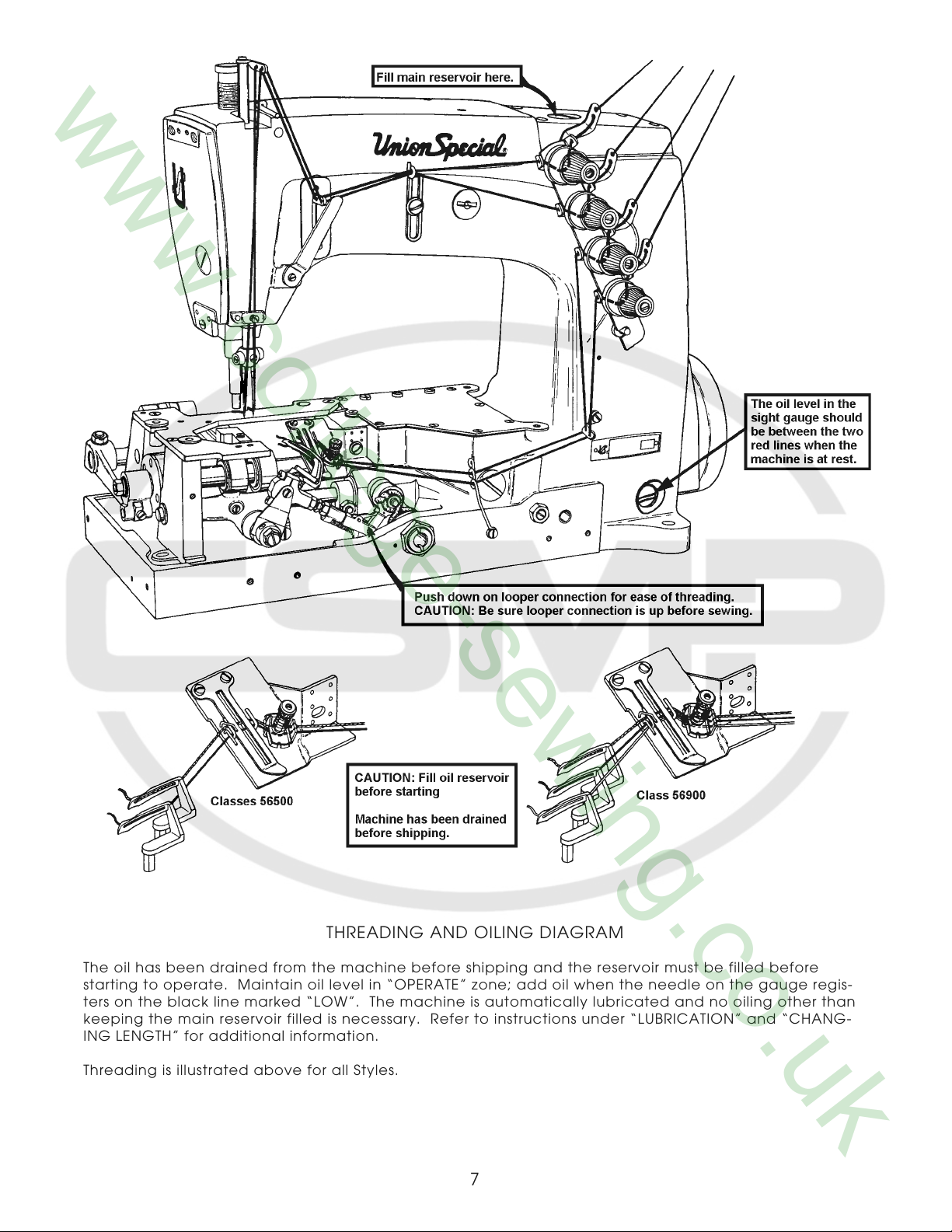
THREADING AND OILING DIAGRAM
The oil has been drained from the machine before shipping and the reservoir must be filled before
starting to operate. Maintain oil level in “OPERATE” zone; add oil when the needle on the gauge regis-
ters on the black line marked “LOW”. The machine is automatically lubricated and no oiling other than
keeping the main reservoir filled is necessary. Refer to instructions under “LUBRICATION” and “CHANG-
ING LENGTH” for additional information.
Threading is illustrated above for all Styles.
7
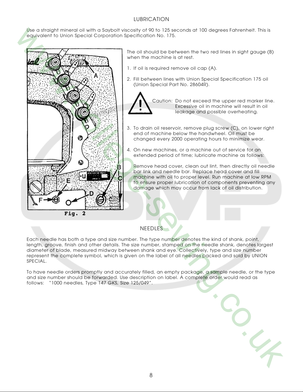
LUBRICATION
Use a straight mineral oil with a Saybolt viscosity of 90 to 125 seconds at 100 degrees Fahrenheit. This is
equivalent to Union Special Corporation Specification No. 175.
The oil should be between the two red lines in sight gauge (B)
when the machine is at rest.
1. If oil is required remove oil cap (A).
2. Fill between lines with Union Special Specification 175 oil
(Union Special Part No. 28604R).
Caution: Do not exceed the upper red marker line.
Excessive oil in machine will result in oil
leakage and possible overheating.
3. To drain oil reservoir, remove plug screw (C), on lower right
end of machine below the handwheel. Oil must be
changed every 2000 operating hours to minimize wear.
4. On new machines, or a machine out of service for an
extended period of time; lubricate machine as follows:
Remove head cover, clean out lint, then directly oil needle
bar link and needle bar. Replace head cover and fill
machine with oil to proper level. Run machine at low RPM
to ensure proper lubrication of components preventing any
damage which may occur from lack of oil distribution.
NEEDLES
Each needle has both a type and size number. The type number denotes the kind of shank, point,
length, groove, finish and other details. The size number, stamped on the needle shank, denotes largest
diameter of blade, measured midway between shank and eye. Collectively, type and size number
represent the complete symbol, which is given on the label of all needles packed and sold by UNION
SPECIAL.
To have needle orders promptly and accurately filled, an empty package, a sample needle, or the type
and size number should be forwarded. Use description on label. A complete order would read as
follows: “1000 needles, Type 147 GKS, Size 125/049”.
8
NEEDLES (CONT.)
Type No. Description and Sizes
128 GAS Round shank, round point, short, double groove, struck groove, ball eye, spotted, chromium
plated - sizes 080/032, 090/036, 100/040, 110/044, 125/049, 140/054, 150/060, 170/067.
128 GJS Round shank, RG chain stitch point, short, double groove, struck groove, ball eye, spotted,
conical blade feature, chromium plated - sizes 090/036, 100/040, 110/044, 125/049, 140/054.
147 GKS Round shank, round point, long, double groove, struck groove, oversize ball eye, spotted,
short point, standard eye and grooves, chromium plated - sizes 090/036, 100/040, 110/044,
125/049, 140/054.
Selection of proper needle size is determined by size of the thread used. Thread should pass freely
through needle eye in order to produce a good stitch formation.
ADJUSTING INSTRUCTIONS
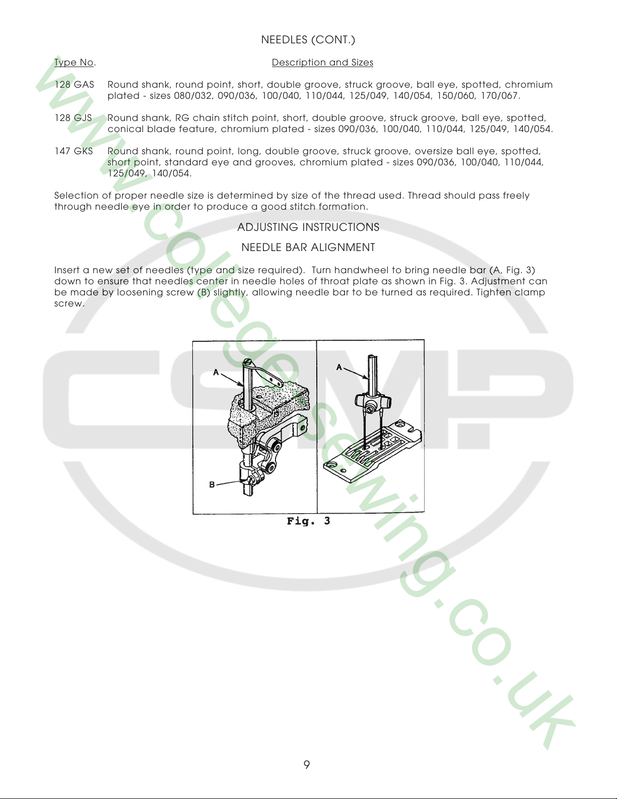
NEEDLE BAR ALIGNMENT
Insert a new set of needles (type and size required). Turn handwheel to bring needle bar (A, Fig. 3)
down to ensure that needles center in needle holes of throat plate as shown in Fig. 3. Adjustment can
be made by loosening screw (B) slightly, allowing needle bar to be turned as required. Tighten clamp
screw.
9
SYNCHRONIZING LOOPER AND NEEDLE MOTIONS
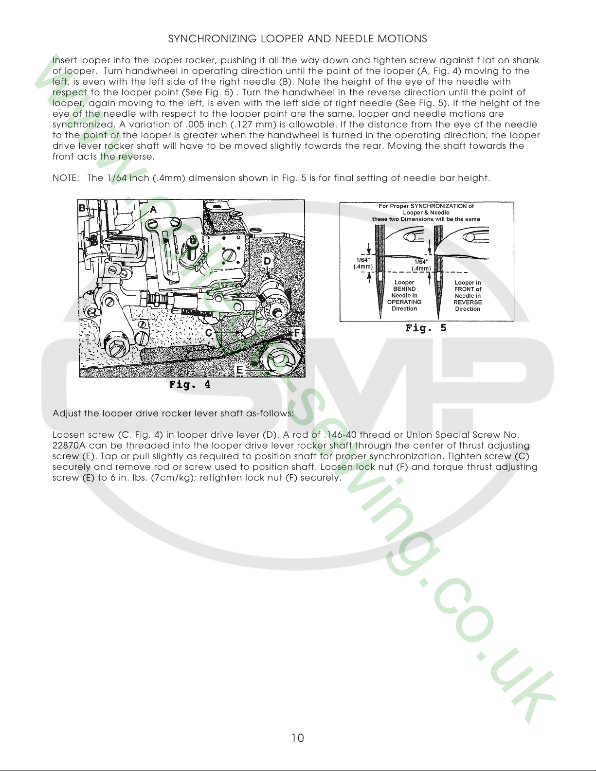
Insert looper into the looper rocker, pushing it all the way down and tighten screw against f lat on shank
of looper. Turn handwheel in operating direction until the point of the looper (A, Fig. 4) moving to the
left, is even with the left side of the right needle (B). Note the height of the eye of the needle with
respect to the looper point (See Fig. 5) . Turn the handwheel in the reverse direction until the point of
looper, again moving to the left, is even with the left side of right needle (See Fig. 5). If the height of the
eye of the needle with respect to the looper point are the same, looper and needle motions are
synchronized. A variation of .005 inch (.127 mm) is allowable. If the distance from the eye of the needle
to the point of the looper is greater when the handwheel is turned in the operating direction, the looper
drive lever rocker shaft will have to be moved slightly towards the rear. Moving the shaft towards the
front acts the reverse.
NOTE: The 1/64 inch (.4mm) dimension shown in Fig. 5 is for final setting of needle bar height.
Adjust the looper drive rocker lever shaft as-follows:
Loosen screw (C, Fig. 4) in looper drive lever (D). A rod of .146-40 thread or Union Special Screw No.
22870A can be threaded into the looper drive lever rocker shaft through the center of thrust adjusting
screw (E). Tap or pull slightly as required to position shaft for proper synchronization. Tighten screw (C)
securely and remove rod or screw used to position shaft. Loosen lock nut (F) and torque thrust adjusting
screw (E) to 6 in. lbs. (7cm/kg); retighten lock nut (F) securely.
10
SYNCHRONIZING LOOPER AND NEEDLE MOTIONS (CONT.)
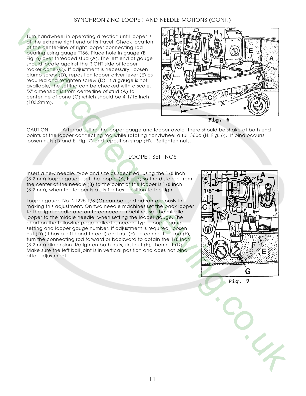
Turn handwheel in operating direction until looper is
at the extreme right end of its travel. Check location
of the center-line of right looper connecting rod
bearing using gauge TT35. Place hole in gauge (B,
Fig. 6) over threaded stud (A). The left end of gauge
should locate against the RIGHT side of looper
rocker cone (C). If adjustment is necessary, loosen
clamp screw (D), reposition looper driver lever (E) as
required and retighten screw (D). If a gauge is not
available, the setting can be checked with a scale.
"X" dimension is from centerline of stud (A) to
centerline of cone (C) which should be 4 1/16 inch
(103.2mm).
CAUTION: After adjusting the looper gauge and looper avoid, there should be shake at both end
points of the looper connecting rod while rotating handwheel a full 360o (H, Fig. 6). If bind occurrs
loosen nuts (D and E, Fig. 7) and reposition strap (H). Retighten nuts.
LOOPER SETTINGS
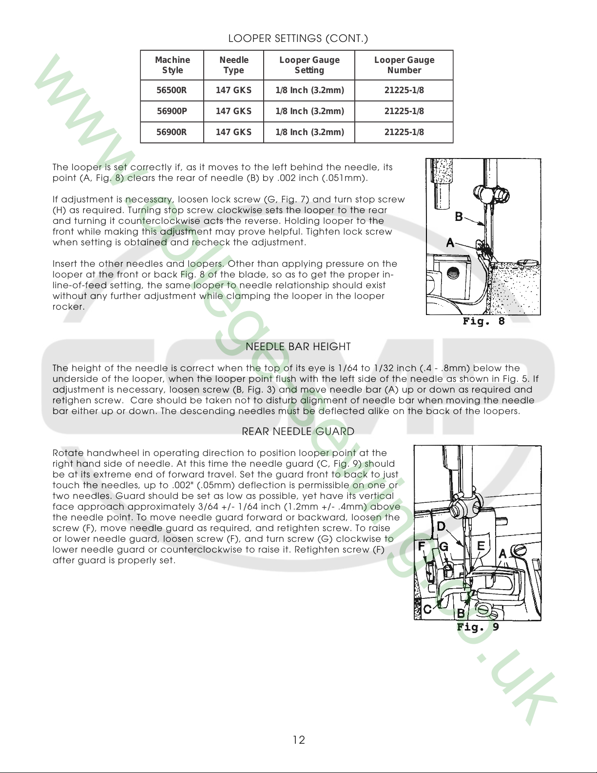
Insert a new needle, type and size as specified. Using the 1/8 inch
(3.2mm) looper gauge, set the looper (A, Fig. 7) so the distance from
the center of the needle (B) to the point of the looper is 1/8 inch
(3.2mm), when the looper is at its farthest position to the right.
Looper gauge No. 21225-1/8 (C) can be used advantageously in
making this adjustment. On two needle machines set the back looper
to the right needle and on three needle machines set the middle
looper to the middle needle, when setting the looper gauge. The
chart on the following page indicates needle Type, looper gauge
setting and looper gauge number. if adjustment is required, loosen
nut (D) (it has a left hand thread) and nut (E) on connecting rod (F),
turn the connecting rod forward or backward to obtain the 1/8 inch
(3.2mm) dimension. Retighten both nuts, first nut (E), then nut (D).
Make sure the left ball joint is in vertical position and does not bind
after adjustment.
11
LOOPER SETTINGS (CONT.)
enihcaM
elytS
R00565SKG741)mm2.3(hcnI8/18/1-52212
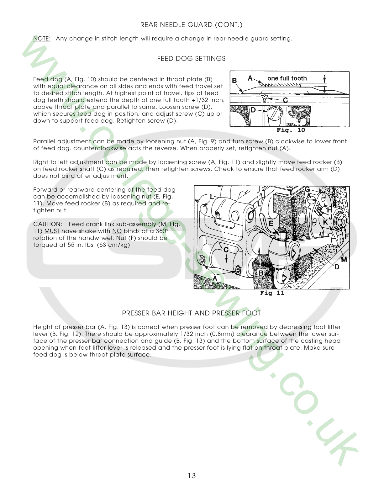
The looper is set correctly if, as it moves to the left behind the needle, its
point (A, Fig. 8) clears the rear of needle (B) by .002 inch (.051mm).
If adjustment is necessary, loosen lock screw (G, Fig. 7) and turn stop screw
(H) as required. Turning stop screw clockwise sets the looper to the rear
and turning it counterclockwise acts the reverse. Holding looper to the
front while making this adjustment may prove helpful. Tighten lock screw
when setting is obtained and recheck the adjustment.
Insert the other needles and loopers. Other than applying pressure on the
looper at the front or back Fig. 8 of the blade, so as to get the proper in-
line-of-feed setting, the same looper to needle relationship should exist
without any further adjustment while clamping the looper in the looper
rocker.
P00965SKG741)mm2.3(hcnI8/18/1-52212
R00965SKG741)mm2.3(hcnI8/18/1-52212
eldeeN
epyT
eguaGrepooL
gnitteS
eguaGrepooL
rebmuN
NEEDLE BAR HEIGHT
The height of the needle is correct when the top of its eye is 1/64 to 1/32 inch (.4 - .8mm) below the
underside of the looper, when the looper point flush with the left side of the needle as shown in Fig. 5. If
adjustment is necessary, loosen screw (B, Fig. 3) and move needle bar (A) up or down as required and
retighen screw. Care should be taken not to disturb alignment of needle bar when moving the needle
bar either up or down. The descending needles must be deflected alike on the back of the loopers.
REAR NEEDLE GUARD
Rotate handwheel in operating direction to position looper point at the
right hand side of needle. At this time the needle guard (C, Fig. 9) should
be at its extreme end of forward travel. Set the guard front to back to just
touch the needles, up to .002" (.05mm) deflection is permissible on one or
two needles. Guard should be set as low as possible, yet have its vertical
face approach approximately 3/64 +/- 1/64 inch (1.2mm +/- .4mm) above
the needle point. To move needle guard forward or backward, loosen the
screw (F), move needle guard as required, and retighten screw. To raise
or lower needle guard, loosen screw (F), and turn screw (G) clockwise to
lower needle guard or counterclockwise to raise it. Retighten screw (F)
after guard is properly set.
12
REAR NEEDLE GUARD (CONT.)
NOTE: Any change in stitch length will require a change in rear needle guard setting.
FEED DOG SETTINGS
Feed dog (A, Fig. 10) should be centered in throat plate (B)
with equal clearance on all sides and ends with feed travel set
to desired stitch length. At highest point of travel, tips of feed
dog teeth should extend the depth of one full tooth +1/32 inch,
above throat plate and parallel to same. Loosen screw (D),
which secures feed dog in position, and adjust screw (C) up or
down to support feed dog. Retighten screw (D).
Parallel adjustment can be made by loosening nut (A, Fig. 9) and turn screw (B) clockwise to lower front
of feed dog, counterclockwise acts the reverse. When properly set, retighten nut (A).
Right to left adjustment can be made by loosening screw (A, Fig. 11) and slightly move feed rocker (B)
on feed rocker shaft (C) as required, then retighten screws. Check to ensure that feed rocker arm (D)
does not bind after adjustment.
Forward or rearward centering of the feed dog
can be accomplished by loosening nut (E, Fig.
11). Move feed rocker (B) as required and re-
tighten nut.
CAUTION: Feed crank link sub-assembly (M, Fig.
MUST have shake with NO binds at a 360°
11)
rotation of the handwheel. Nut (F) should be
torqued at 55 in. lbs. (63 cm/kg).
PRESSER BAR HEIGHT AND PRESSER FOOT
Height of presser bar (A, Fig. 13) is correct when presser foot can be removed by depressing foot lifter
lever (B, Fig. 12). There should be approximately 1/32 inch (0.8mm) clearance between the lower sur-
face of the presser bar connection and guide (B, Fig. 13) and the bottom surface of the casting head
opening when foot lifter lever is released and the presser foot is lying flat on throat plate. Make sure
feed dog is below throat plate surface.
13
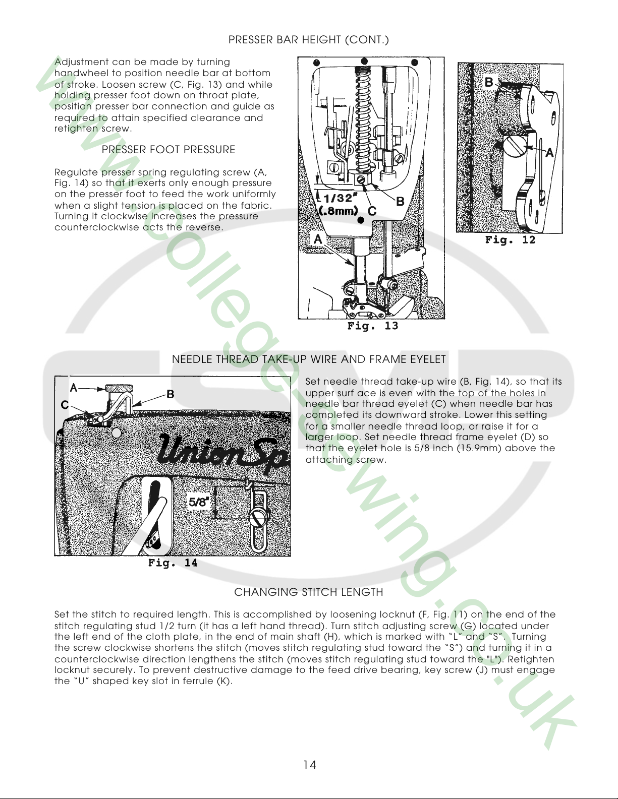
PRESSER BAR HEIGHT (CONT.)
Adjustment can be made by turning
handwheel to position needle bar at bottom
of stroke. Loosen screw (C, Fig. 13) and while
holding presser foot down on throat plate,
position presser bar connection and guide as
required to attain specified clearance and
retighten screw.
PRESSER FOOT PRESSURE
Regulate presser spring regulating screw (A,
Fig. 14) so that it exerts only enough pressure
on the presser foot to feed the work uniformly
when a slight tension is placed on the fabric.
Turning it clockwise increases the pressure
counterclockwise acts the reverse.
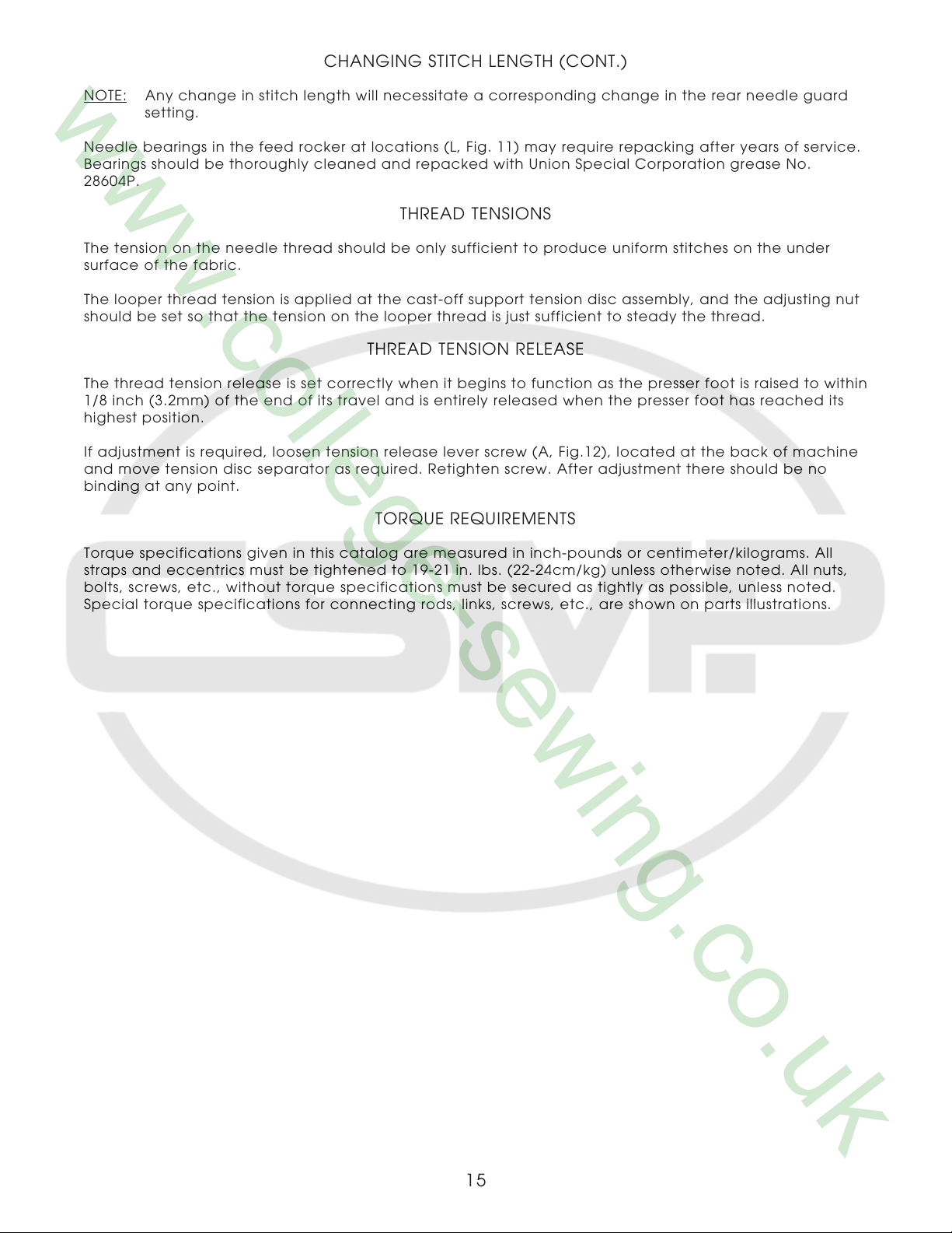
NEEDLE THREAD TAKE-UP WIRE AND FRAME EYELET
Set needle thread take-up wire (B, Fig. 14), so that its
upper surf ace is even with the top of the holes in
needle bar thread eyelet (C) when needle bar has
completed its downward stroke. Lower this setting
for a smaller needle thread loop, or raise it for a
larger loop. Set needle thread frame eyelet (D) so
that the eyelet hole is 5/8 inch (15.9mm) above the
attaching screw.
CHANGING STITCH LENGTH
Set the stitch to required length. This is accomplished by loosening locknut (F, Fig. 11) on the end of the
stitch regulating stud 1/2 turn (it has a left hand thread). Turn stitch adjusting screw (G) located under
the left end of the cloth plate, in the end of main shaft (H), which is marked with “L” and “S”. Turning
the screw clockwise shortens the stitch (moves stitch regulating stud toward the “S”) and turning it in a
counterclockwise direction lengthens the stitch (moves stitch regulating stud toward the "L"). Retighten
locknut securely. To prevent destructive damage to the feed drive bearing, key screw (J) must engage
the “U” shaped key slot in ferrule (K).
14
CHANGING STITCH LENGTH (CONT.)
NOTE: Any change in stitch length will necessitate a corresponding change in the rear needle guard
setting.
Needle bearings in the feed rocker at locations (L, Fig. 11) may require repacking after years of service.
Bearings should be thoroughly cleaned and repacked with Union Special Corporation grease No.
28604P.
THREAD TENSIONS
The tension on the needle thread should be only sufficient to produce uniform stitches on the under
surface of the fabric.
The looper thread tension is applied at the cast-off support tension disc assembly, and the adjusting nut
should be set so that the tension on the looper thread is just sufficient to steady the thread.
THREAD TENSION RELEASE
The thread tension release is set correctly when it begins to function as the presser foot is raised to within
1/8 inch (3.2mm) of the end of its travel and is entirely released when the presser foot has reached its
highest position.
If adjustment is required, loosen tension release lever screw (A, Fig.12), located at the back of machine
and move tension disc separator as required. Retighten screw. After adjustment there should be no
binding at any point.
TORQUE REQUIREMENTS
Torque specifications given in this catalog are measured in inch-pounds or centimeter/kilograms. All
straps and eccentrics must be tightened to 19-21 in. lbs. (22-24cm/kg) unless otherwise noted. All nuts,
bolts, screws, etc., without torque specifications must be secured as tightly as possible, unless noted.
Special torque specifications for connecting rods, links, screws, etc., are shown on parts illustrations.
15
SPECIAL INSTRUCTIONS
NEEDLE LEVER
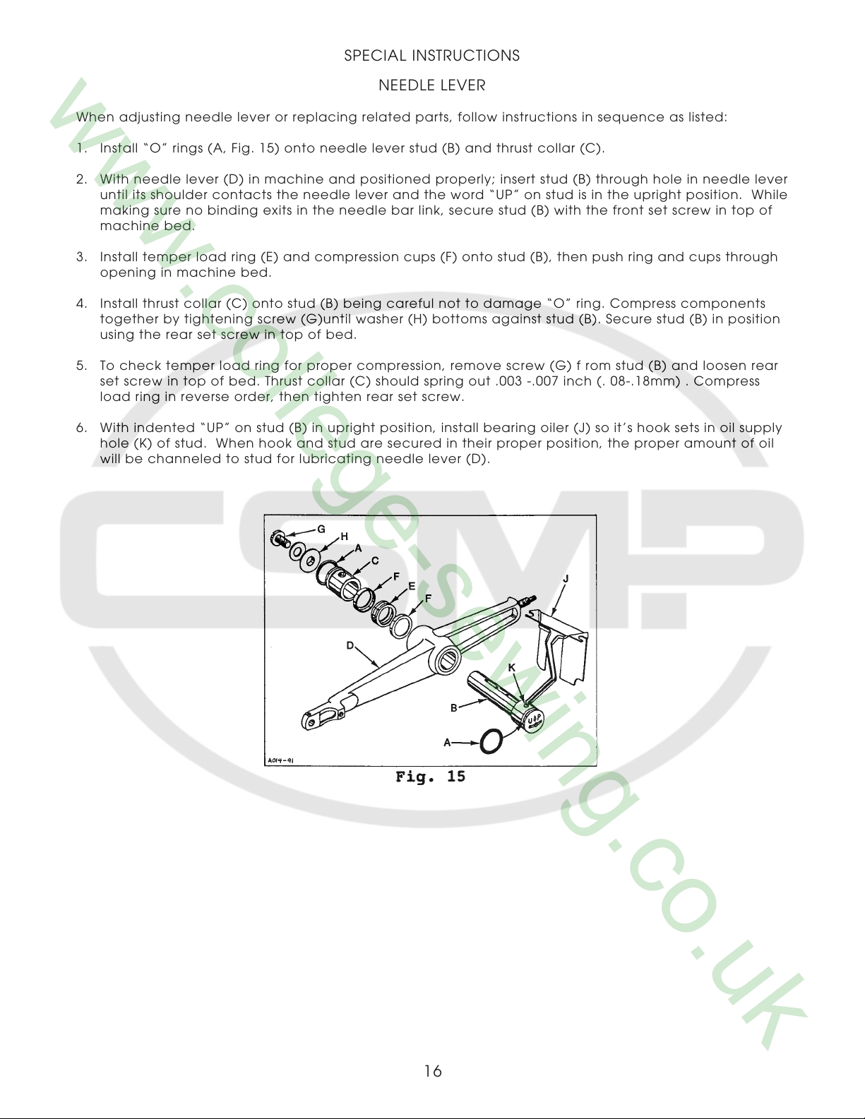
When adjusting needle lever or replacing related parts, follow instructions in sequence as listed:
1. Install “O” rings (A, Fig. 15) onto needle lever stud (B) and thrust collar (C).
2. With needle lever (D) in machine and positioned properly; insert stud (B) through hole in needle lever
until its shoulder contacts the needle lever and the word “UP” on stud is in the upright position. While
making sure no binding exits in the needle bar link, secure stud (B) with the front set screw in top of
machine bed.
3. Install temper load ring (E) and compression cups (F) onto stud (B), then push ring and cups through
opening in machine bed.
4. Install thrust collar (C) onto stud (B) being careful not to damage “O” ring. Compress components
together by tightening screw (G)until washer (H) bottoms against stud (B). Secure stud (B) in position
using the rear set screw in top of bed.
5. To check temper load ring for proper compression, remove screw (G) f rom stud (B) and loosen rear
set screw in top of bed. Thrust collar (C) should spring out .003 -.007 inch (. 08-.18mm) . Compress
load ring in reverse order, then tighten rear set screw.
6. With indented “UP” on stud (B) in upright position, install bearing oiler (J) so it’s hook sets in oil supply
hole (K) of stud. When hook and stud are secured in their proper position, the proper amount of oil
will be channeled to stud for lubricating needle lever (D).
16
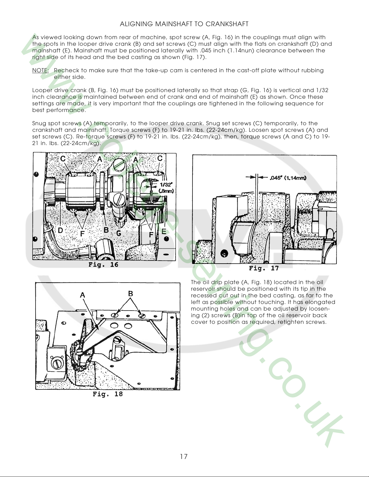
ALIGNING MAINSHAFT TO CRANKSHAFT
As viewed looking down from rear of machine, spot screw (A, Fig. 16) in the couplings must align with
the spots in the looper drive crank (B) and set screws (C) must align with the flats on crankshaft (D) and
mainshaft (E). Mainshaft must be positioned laterally with .045 inch (1.14nun) clearance between the
right side of its head and the bed casting as shown (Fig. 17).
NOTE: Recheck to make sure that the take-up cam is centered in the cast-off plate without rubbing
either side.
Looper drive crank (B, Fig. 16) must be positioned laterally so that strap (G, Fig. 16) is vertical and 1/32
inch clearance is maintained between end of crank and end of mainshaft (E) as shown. Once these
settings are made, it is very important that the couplings are tightened in the following sequence for
best performance.
Snug spot screws (A) temporarily, to the looper drive crank. Snug set screws (C) temporarily, to the
crankshaft and mainshaft. Torque screws (F) to 19-21 in. lbs. (22-24cm/kg). Loosen spot screws (A) and
set screws (C). Re-torque screws (F) to 19-21 in. lbs. (22-24cm/kg), then, torque screws (A and C) to 19-
21 in. lbs. (22-24cm/kg).
The oil drip plate (A, Fig. 18) located in the oil
reservoir should be positioned with its tip in the
recessed cut out in the bed casting, as far to the
left as possible without touching. It has elongated
mounting holes and can be adjusted by loosen-
ing (2) screws (B)in top of the oil reservoir back
cover to position as required, retighten screws.
17
 Loading...