

Page 1
INDUSTRIAL
SEWING
FINEST
QUALITY
CLASSES
61800
62200
®
C 0 L U M B I A®
MACHINES
S
TYLE
61800
STREAMLINED
CATALOG
NEEDLE
No.
101
/
•
LO
/
/
/
/
VERTICAL
CKSTITCH
UNION SPECIAL
C
HI
CAGO
CA
.
FEED
HOOK
MACHINES
CORPORATION
J
Page 2
Catalog
INSTRUCTIONS
No.
FOR
101
R
Streamlined,
ADJUSTING
Vertical
61800
61800
61800
618
0 0
61800
LIST
CLASSES
Hook,
61800
D
H
CA
DA
HA
c
62200
62200
AND
and
OF
FOR
61800,
Needle
Styles
OPERATING
PARTS
62200
Feed
62200
62200
62200
62200
KA
LA
G
H
62200
62200
Lockstitch
K
L
GA
HA
Machin
e s
Rights
Copyright
Union
Reserved
First
Special
Edition
1960,
by
Corporation
in
All
1968
Countries
UNION SPECIAL CORPORATION
INDUSTRIAL
Printed
SEWING
CHICAGO
in
U.S.A.
2
MACHINES
May,
1980
Page 3
IDENTIFICATION
OF
MACHINES
Each
into
special.
tain
letter
suffixed
Styles
which
"Class
This
herein.
in
these
are
direction
Streamlined
Feed
with
Enclosed
Manual
Hook
UNION
the
name
Standard
the
letter
"Z
".
to
differs
61800".
catalog
It
Classes.
given
and
Drop
Locking
Automatic
Head
Mechanism.
plate
"Z
When
the
Standard
of
machines
from
can
also
from
of
handwheel
STYLES
Flat
Feed.
Device.
Lubrication.
SPECIAL
on
Style' numbers
".
Example:
only
the
applies
be
Reference
the
operator's
Bed
Rotary
Lubricating
Maximum
machine
the
minor
Style
similar
Style
APPLICATION
specifically
applied
is
toward
OF
Lockstitch
External
Separate
is
machine.
have
"Style
changes
number.
in
construction
number.
with
to
directions.
position
the
MACHINES
Machines.
Hook.
Needle
System
Work
Vertical
Space
identified
Style
discretion
operator.
Reservoir
r:tumbers
one
or
61800
are
made
Example:
in
that
OF
to
the
while
IN
CLASS
Hook
Thread
for
to
by a Style
more
C".
Special
in a standard
"Style
are
it
CATALOG
Standard
to
some
such
as
seated
61800
Light.
Main
Right
Medium
Shaft.
Tension
Driving
for
Automatic
of
are
classified
letters
Style
61800
grouped
contains
Styles
Special
right.
at
AND
Thumb
Mechanism.
Needle
number
suffixed,
under a Class
no
left.
the
and
Mechanism.
Bar
which
as
numbers
machine,
CZ
".
letters.
of
machines
Styles
front.
machine.
62200
Heavy
Screw
Lubrication
Stitch
10
is
standard
but
never
contain
of
back.
Operating
Duty.
Regulator
One
Reservoir
Automatic
Inches.
stamp
a
number
Example:
as
machines
of
ed
and
con-
the
"Z"
listed
etc
Needle
or
Rotary
is
••
*
*
*
*
61800
61800
61800
61800
61800
61800
C
seaming
hinged
180
ommended
D
waistbands
compensating
24-3
Specify
H
seaming
the
is
speed
CA
head.
DA
head.
HA
head.
Single
operations
bottom
GXS
use
maximum
or
Single
cord
needle
Single
operations
of
4000
Same
Same
Same
Needle
presser
180
speed
Needle
of
trousers
presser
is
maximum
Needle
heavy
usable
R.
P.M.
as
Style
as
Style
as
Style
Machine
on
light.
foot.
GYS
needle.
4000
R.
Machine
foot.
type
and
Machinewithmanuallubricationforhead.
on
medium
threads;
thread
61800
61800
61800
P.M.
and
usable
size.
equipped
size.
c.
D.
H.
with
manual
medium
24-3
Specify
with
manual
similar
to
compensate
thread
Maximum
and
Type
except
except
except
lubrication
and
cord
is
needle
operations;
size.
medium
with
hinged
182
equipped
equipped
equipped
heavy
maximum
lubrication
for
Type
recommended
heavy
GAS
weight
type
equipped
uneven
180
weight
bottom
needle.
with
with
with
for
head.
materials;
usable
and
size.
for
head.
thickness
GXS
speed
materials.
presser
Maximum
automatic
automatic
automatic
for
miscellaneous
equipped
thread
with
or
formiscellaneous
size.
Maximum
for
top
stitching
double
of
materials.
180
GYS
4
000
R.
requiring
foot.
lubrication
lubrication
lubrication
16-4
recommended
needle.
with
Type
rec•
action
P.M.
cord
for
for
for
*
DISCONTINUED
- In
repair.
most
instances,
component
parts
can
3
be
ordered
for
customer
Page 4
*
62200
STYLES
G
Two
seaming
and
other
medium
Type
gauges
ommended
and
180
Nos.
OF
Needle
operations
foundation
heavy
GXS
or
8,
12,
speed 4 000
MACHINES
Machine
on
garments,
weight
180
16,
work
articles.
GYS
20,
R.
P.M.
with
IN
CLASS
manual
shirts,
jackets.
needle.
24,
overalls,
24-3
Specify
28
and
61800
lubrication
shop
cord
32.
AND
work
coats.
is
needle
Specify
62200
for
head,
pants.
aprons
maximum
type
gauge.
(Continued)
for
miscellaneous
dungarees,
and
similar
usable
and
thread
size.
Maximum
corsets
light,
size.
Standard
rec-
* 622
*
62200
*
62200
62200
62200
00
H
Two
operations
canvas.
cord
Nos.
4000
along
taping
reel
wide
180
4000
machine
with
No.
head.
head.
is
12,
R.P.M.
K
furnished
tape
GYS
R.P.M.
L
positive
12
GA
HA
Two
Two
Same
Same
Needle
on
upholstery
maximum
16,
Needle
the
edges
top.
bottom,
and
needle.
Needle
for
only.
as
as
Machine
overalls.
usable
20,
24,
Machine
and
with
finishes
Standard
Machine
chaining
chaining
Maximum
Style
Style
and
similar
28
and
when
gore
machine.
5/16
on
short
parts.
recommended
62200
62200
with
manual
western
thread
32.
with
turning
seams
Folder
inch
gauge
with
operations
Type
G,
except
H.
except
type
items
size.
Specify
manual
corners,
and
wide.
No.
manual
180GXS
lubrication
dungarees,
requiring
Type
gauge.
lubrication
reinforcement
has
Seam
12
only.
lubrication
such
speed
equipped
equipped
the
182
GAS
Maximum
while
1/32
inch
Specification
Maximum
as
or
180GYS
4000
with
with
for
head,
jackets,
use
of
needle.
for
head,
taping
seams
capacity.
for
hemming
needle.
R.
P.M.
automatic
automatic
for
miscellaneous
medium
heavy
recommended
brassieres,
recommended
head,
pockets.
thread.
Standard
for
quality control
on
~orsets.
takes
301-LSk-2.
general
Standard
lubrication
lubrication
weight
16-4
gauges
speed
and
for
Tape
5/8
inch
Type
speed
utility
Equipped
gauge
for
for
622
00
KA
Same
head.
622 00
denotes
number,
sured
number
packaged
sample
on
*
DISCONTINUED
LA
head.
Each
To
label.
Same
UNION
the
stamped
in
thousandths
represent the
and sold
have
needle,
Acomplete
kind
needle
as
Style
as
Style
SPECIAL
of
shank.
on
the
of
complete
by
Union
orders
or
the
type
order
-
In
most
repair.
62200
622 00
needle
point,
needle
an
wouldread:"lOOONeedles,
instances,
K,
L,
has
length.
shank.
inch
across
symbol,
Special.
promptly
and
size
except
except
NEEDLES
both a type
number
component
groove.
denotes
the
which
and
accurately
4
equipped
equipped
should
and
largest
eye.
is
parts
with
with
finish
Collectively,
given
automatic
automatic
size
number. The
and
diameter
on
filled, an
be
forwarded.
Type
can
lubrication
lubrication
other
the
180GXS, size
be
details.
of
the
label
empty
ordered
the
type
Use
type
number
Th
blade,
and
of
all needles
p:tckage
description
090/036".
for cus
for
for
e s
ize
mea-
size
, a
tomer
Page 5
The
by
this
able,
but
results.
criptions,
type
catalog
the
The
and
numbers
are giv
ones
indicated
type
numbers
the
siz
NEEDLES
of the needles r e
en
in the
machine styl
are thos
e r e
of the r e
es
available
are
(Continued)
commendedfor
e de
scription.
commend
commend
listed
ed
ed
below:
each
to
produce
needles
style
of
Other
the
together
machine
needles
most
with
covered
are
avail-
satisfactory
their
des-
Type
180
180
182
No.
GXS
GYS
GAS
Selection
should
Success
use
of
a
reputation
more
than
Where
Parts
which
Round
groove,
chromium
125/049, 140/054,
Round
groove,
-
140/054,
Round
groove,
125/049,
of
pass
needles
freely
in
packaged
for
three-quarters
the
too
small
distinguish
shank,
wide
plated-
shank,
wide
sizes
075/029,
150/060.
shank,
struck
140/054,
proper
needle
through
the
operation
under
producing
construction
for a complete
one
part
Description
round
angle
point,
groove,
sizes
150/060.
round
angle
point,
groove,
080/032,
round
point,
groove,
150/060,
size
needle
of
our
highest
is
eye
UNION
brand
quality
of a century.
IDENTIFYING
permits,
catalog
from
another
and
lockstitch,
struck
075/029,
lockstitch,
struck
090/036,
lockstitch,
deep
spot,
170/067.
determined
in
order
SPECIAL
name,
needles
each
part
stamping
that
is
Sizes
short
groove,
080/032,090/036,
short
groove,
deep
100/040,
long
chromium
by
size
to
produce a good
machines
~
in
materials
PARTS
is
stamped
are
identified
similar
in
appearance.
length,
deep
length,
spot,
length,
plated-
of
thread
can
be
,
and
with
ball
spot,
eye,
ball
100/040,
ball
eye,
chromium
110/044,
ball
eye,
sizes
used.
stitch
formation.
secured
which
is
workmanship
its
part
by
letter
single
point,
110/044,
single
plated
125/049,
single
110/044,
Thread
only
backed
number.
symbols
by
by
for
Part
numbers
appear.
IMPORTANT!
Prices
forwarded
wise
ploded
be
directed.
This
views
seen
catalog
in
blackened
the
illustration
scriptions
are
f.
o.
their
area
and
net
b.
A
of
various
where
will
the
represent
ON
ALL
OF
MACHINE
cash
shipping
charge
has
been
actual
the
be
number
the
same
ORDERS,
PLEASE
FOR
and
subject
point.
is
made
Parcel
to
cover
ORDERING
ILLUSTRATIONS
arranged
sections
position
parts
fit
of
in
to
the
the
in
found a listing
of
pieces
part,
WHICH
TERMS
to
change
Post
the
REPAIR
simplify
mechanism
machine.
the
assembled
of
the
required
regardless
INCLUDE
PART
IS
without
shipments
postage
PARTS
the
ordering
are
Small
machine.
parts
in
with
the
of
the
catalog
PART
NAME
ORDERED.
notice.
are
insured
and
insurance.
of
shown
so
keyline
On
their
part
particular
All
repair
that
views
the
numbers,
view
in
which
AND
STYLE
shipments
unless
other-
parts.
the
parts
show
page
opposite
being shown.
they
are
Exmay
by
de-
a
5
Page 6
ILLUSTRATIONS
(Continued)
Numbers
the
position
in
ordering
Component
indicated
assembly.
Ref.
No.
50
51
It
will
listed.
mended,
Basically,
needle
for
is
by
when
be
the
machine,
the
changed.
this
catalog,
the
mentioned
illustration.
in
of
parts.
by
indenting
Example:
Part
No.
51239
22729
be
noted
The
reason
so
the
standard
In
parts
in
the
first
that
part
parts
L
c
in
complete
Classes
while
machine
those
no
specific
for
the
the
column
in
the
Always
of
sub.,.assemblies
their
Ball
the
is
that
61800
Class
cases
various
description,
descriptions
Joint
Screw,
above
replacement
sub-assembly
and
are
where a part
usage
are
reference
illustration.
use
the
part
Feed
example
62200
62200
the
machines
and
Ball
is a two
same.
will
if
Driving
be
numbers
Reference
number
which
under
Description
Joint
that
of
should
are
the
In
is
mentioned
are
necessary,
can
Connection,
Connection-------------------
the
these
be
same
needle
some
common
not
numbers
listed
be
the
description
bearing
parts
ordered.
except
machine;
cases,
to
in
the
same,
the
only,
furnished
individually
all
the
difference
and
should
in
the
upper-----------
and
the
Class
therefore,
the
quantity
the
machines
description.
the
specific
merely'
never
second
for
of
the
ball
is
61800
will
indicate
be
used
column.
repairs
main
stud
not
is a single
all
requirement
However,
usage
be
shown
are
sub-
Amt.
Re
1
2
are
not
recom-
parts
covered
will
q.
in
At
the
this
catalog.
the
part
number
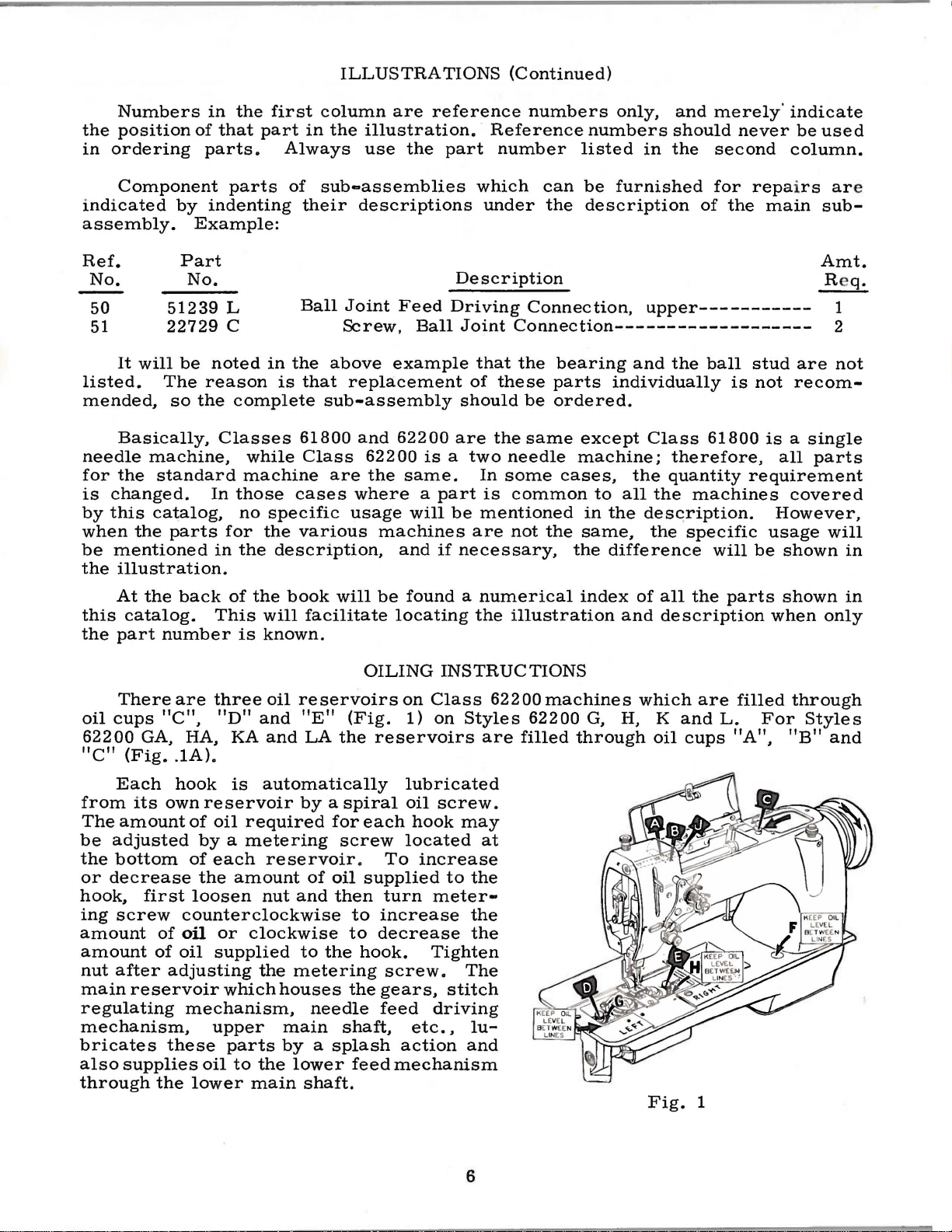
There
oil
cups
62200
"C"
Each
from
The
be
adjusted
the
bottom
or
decrease
hook,
ing
screw
amount
amount
nut
after
main
regulating
mechanism,
bricates
also
through
"C",
GA, HA, KA
(Fig
•.
its
own
amount
first
of
of
reservoir
these
supplies
the
back
are
1A).
hook
oil
adjusting
of
the
book
This
three
reservoir
of
oil
by a metering
of
each
the
loosen
counterclockwise
oil
supplied
mechanism.
upper
oil
lower
will
is
known.
oil
"D"
and
and
is
automatically
required
reservoir.
amount
nut
or
clockwise
the
which
parts
to
the
main
houses
main
by a splash
will
facilitate
OILING
reservoirs
"E"
by a spiral
and
to
metering
lower
LA
the
for
screw
of
oil
then
the
needle
shaft.
(Fig.
each
supplied
to
to
hook.
the
shaft,
feed
be
found a numerical
locating
on
1)
reservoirs
lubricated
oil
hook
located
To
increase
turn
increase
decrease
screw.
gears,
feed
etc.,
action
mechanism
the
INSTRUCTIONS
Class
on
Styles
are
screw.
may
at
to
the
meter-
the
the
Tighten
The
stitch
driving
lu-
and
illustration
62200
machines
62200
filled
index
G, H, K
through
of
and
all
the
description
which
Fig.
oil
are
and
cups
1
parts
filled
L.
"A",
shown
when
For
"B"
in
only
through
Styles
and
6
Page 7
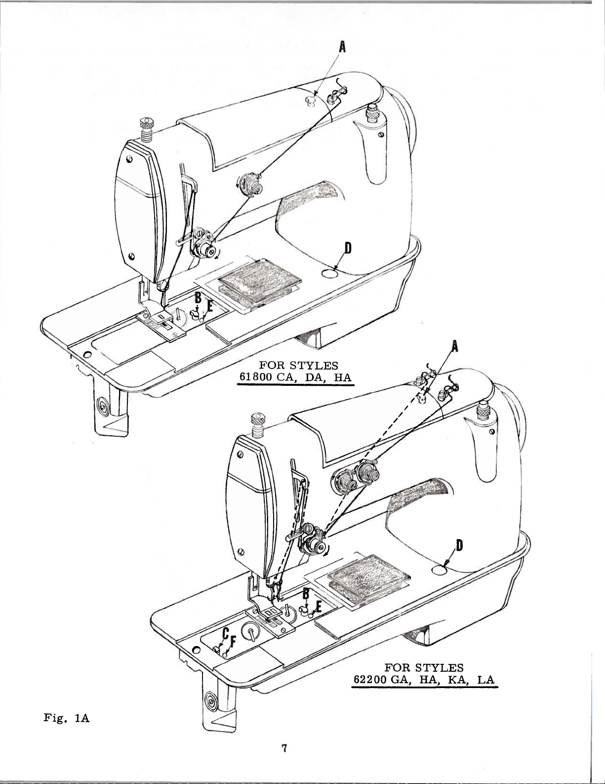
A
FOR
61800
STYLES
CA,
DA,
HA
62200
Fig.
lA
7
FOR
GA,
STYLES
HA,
KA,
LA
Page 8
On
Styles
can
readily
of
oil
in
observed
The
anism,
spectively,
62200
be
the
three
at
the
manually
the
left
on
Styles
G,
observed
main
lucite
oiled
upper
OILING
H,
at
reservoirs
gauges
holes
main
62200
INSTRUCTIONS
K
and
L,
the
lucite
"D",
"E"
"A", "B"
shaft
G,
H,
bearing
K
the
gauges
on
Styles
and
and
and
L.
level
"F",
"F"
"J"
and
(Continued)
of
oil
in
''G"
62200
(Fig.
the
GA,
1A).
(Fig.
needle
the
and
"H"
HA,
1)
lubricates
bar
three
frame
main
(Fig.
KA
1 ).
and
the
pivot
reservo
Th
e l
evel
LA, can
head
mech-
pin,
irs
be
re-
Use a straight
Fahrenheit
lubricate
conditions.
tween
must
that
refilled,
clockwise.
screw
62200
or
are
reservoir,
lines
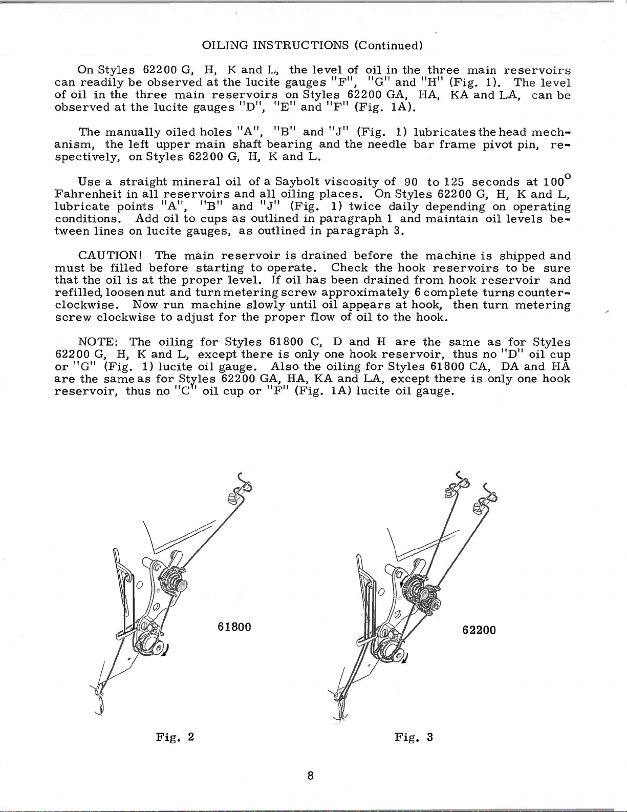
CAUTION!
be
the
loosen
clockwise
NOTE:
G,
"G"
the
(Fig.
same
points
filled
oil
H,
in
all
Add
on
is
at
Now
The
K
as
thus
reservoirs
"A",
oil
lucite
The
before
the
nut
run
to
oiling
and
1)
lucite
for
no
mineral
"B"
to
cups
gauges,
main
starting
proper
and
turn
machine
adjust
for
L,
except
oil
St:rr1es
"C ' oil
oil
of a Saybolt
and
and
as
outlined
as
reservoir
to
level.
metering
slowly
for
the
Styles
there
gauge.
62200
cup
or
all
oiling
"J"
(Fig.
outlined
is
operate.
If
oil
screw
until
proper
61800
is
only
Also
GA,
HA,
"F"
(Fig.
viscosity
places.
1)
twice
in
paragraph
in
paragraph
drained
Check
has
been
approximately
oil
appears
flow
the
of
C, D
one
oiling for
KA
and
1A)
before
drained
oil
and
hook
LA,
lucite
of
90
On
Styles
daily
1
and
3.
the
the
hook
at
hook,
to
the
H
are
reservoir,
Styles
except
oil
to
125
62200
depending
maintain
machine
reservoirs
from
6
hook.
gauge.
hook
complete
the
same
61800
there
then
thus
seconds
G,
H,
on
oil
is
shipped
reservoir
turns
turn
as
no
"D"
CA,
is
DA
only
at
100°
K
and
operating
levels
to
be
sure
counter
metering
for
Styles
oil
and
one
hook
L,
be-
and
and
..
cup
HA
61800
Fi
g. 2 F ig . 3
8
62200
Page 9
THREADING
Thread
machine.
Fig.
The
spot
from
left
2
for
needle
(sometimes
left
and
the
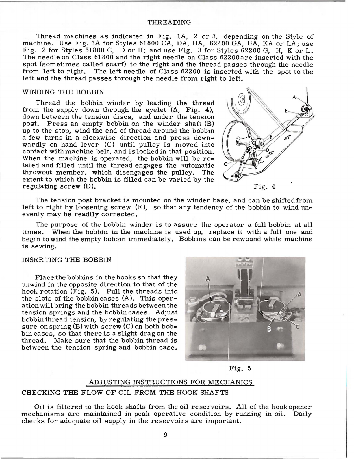
WINDING
Thread
from
down
post.
up
a
wardly
contact
When
tated
to
few
the
between
Press
the
turns
on
with
the
and
throwout
extent
to
regulating
The
tension
left
to
right
evenly
may
machines
Use
Fig.
Styles
on
61800
Class
called
to
right.
thread
THE
the
supply
an
stop,
passes
BOBBIN
bobbin
down
the
tension
empty
wind
in a clockwise
hand
lever
machine
machine
filled
until
member,
which
screw
the
(D).
post
by
loosening
be
readily
as
1A
for
C, D
61800
scarf)
The
winder
through
bobbin
the
end
(C)
belt,
is
operated,
the
which
bobbin
bracket
corrected.
indicated
Styles
or
and
the
to
left
needle
through
the
discs,
on
of
thread
direction
until
and
is
thread
disengages
is
filled
is
mounted
screw
in
61800
H;
and
right
the
right
of
the
needle
by
leading
eyelet
and
under
the
around
and
pulley
locked
the
bobbin
engages
can
(E),
so
Fig.
CA,
use
needle
and
Class
(A,
winder
press
is
in
that
the
the
pulley.
be
varied
on
the
that
1A, 2
DA,
HA,
Fig.
on
the
622 00
from
the
thread
Fig.
the
tension
shaft
the
bobbin
down-
moved
position.
will
be
automatic
by
winder
any
tendency
or
3,
62200
3
for
lass
thread
is
right
4),
(B)
into
ro-
The
the
base,
depending
GA,
Styles
622
pass
insert
to
left.
of
00
ed
and
the
HA,
62200
are
es
throu
with
Fig.
can
bobbin
on
the
KA or·
G,
H,
inserted
gh
the
4
be
shifted
to
Style
LA;
K
with
the
spot
wind
of
use
or
L.
the
needle
to
the
from
un.,.
The
purpose
times.
begin
is
sewing.
to
When
wind
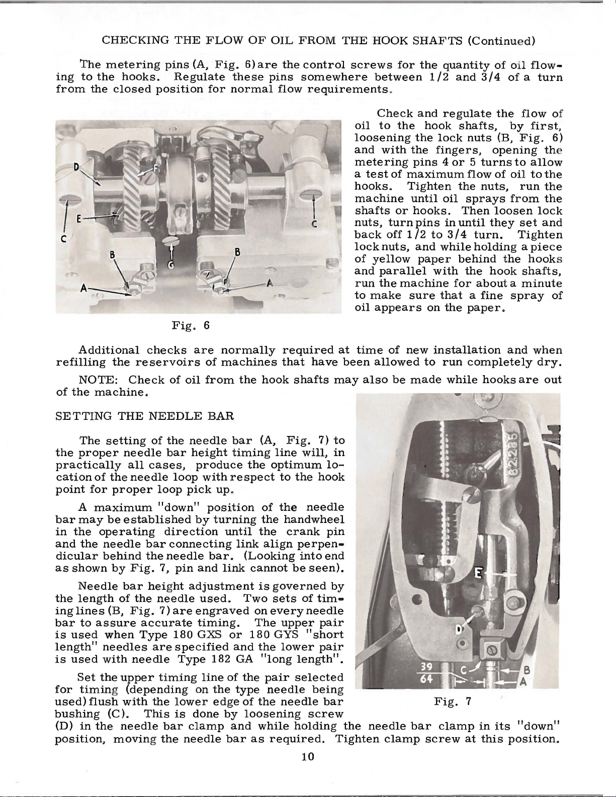
INSERTING
Place
unwind
hook
the
slots
ation
tension
bobbin
sure
bin
cases,
thread.
between
the
in
rotation
of
will
bring
springs
thread
on
spring
Make
the
CHECKING
THE
bobbins
the
the
so
tension
THE
of
the
bobbin
the
empty
BOBBIN
opposite
(Fig.
bobbin
the
bobbin
and
tension,
(B)
with
that
there
sure
ADJUSTING
FLOW
the
bobbin
bobbin
in
the
direction
5).
cases
the
bobbin
by
screw
is a slight
that
spring
OF
winder
in
the
immediately.
hooks
Pull
the
(A).
threads
cases.
regulating
(C)
the
bobbin
and
OIL
is
to
assure
machine
is
used
Bobbins
so
that
they
to
that
of
the
threads
This
between
into
oper-
the
Adjust
the
pres-
on
both
bob-
drag
on
the
thread
bobbin
is
case.
INSTRUCTIONS
FROM
THE
HOOK
the
up,
FOR
SHAFTS
operator
replace
can
be
Fig.
a
it
with a full
rewound
5
MECHANICS
full
bobbin
while
at
all
one
and
machine
Oil
is
mechanisms
checks
for
filtered
adequate
are
to
the
hook
maintained
oil
supply
shafts
in
peak
in
the
from
the
operative
reservoirs
9
oil
reservoirs.
condition
are
important.
by
All
of
running
the
in
hook
oil.
opener
Daily
Page 10
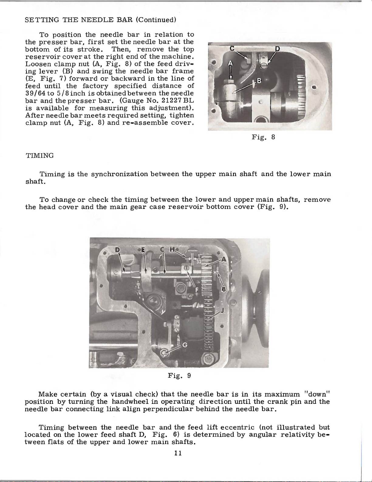
ing
from
CHECKING
The
metering
to
the
the
closed
hooks.
THE
pins
(A,
Regulate
position
FLOW
Fig.
these
for
normal
OF
6)
are
OIL
the
pins
flow
FROM
control
somewhere
requirements
THE
screws
HOOK
for
between
.
SHAFTS
the
quantity
1/2
and
(Continu
of oil
3/4
ed)
flow-
of a turn
Additional
refilling
NOTE:
of
the
machine.
the
reservoirs
Check
Fig.
checks
of
are
oil
6
normally
of
machines
from
the
required
that
hook
have
shafts
oil
loosening
and
metering
a
hooks.
machine
shafts
nuts,
back
lock
of
and
run
to
oil
at
time
been
may
Check
to
with
test
off
nuts,
yellow
parallel
the
make
appears
allowed
also
and
regulate
the
hook
the
lock
the
fingers,
pins 4 or 5 turns
of
maximum
Tighten
until
or
hooks.
turn
1/2
machine
sure
of
new
be
made
oil
pins
in
to
3/4
and
while
paper
with
that a fine
on
the
installation
to
run
while
for
the
flow
shafts,
nuts
flow
the
sprays
Then
until
turn.
holding a piece
behind
the
about a minute
paper.
completely
by
(B,
Fig.
opening the
to
of
oil
nuts,
they
hook
hooks
run
from
loosen
set
Tighten
the
shafts,
spray
and
are
first,
allow
to
the
the
the
lock
and
hook
when
dry.
out
of
6)
s
of
SETTING
The
the
proper
practically
cation
point
A
bar
may
in
the
and
the
dicular
as
shown
Needle
the
length
ing
lines
bar
to
is
used
length"
is
used
Set
for
timing (depending
used)
bushing
(D)
in
position,
THE
setting
needle
all
of
the
for
proper
maximum
be
established
operating
needle
behind
by
bar
of
(B,
assure
when
needles
with
the
upper
flush
with
(C).
the
needle
moving the
NEEDLE
of
cases,
needle
loop
"down"
bar
the
Fig.
height
the
needle
Fig.
accurate
Type
are
needle
timing
the
This
the
needle
bar
height
produce
loop
with
pick up.
by
direction
connecting
needle
7,
pin
and
adjustment
used.
7)
are
engraved
timing.
180
GXS
specified
Type
line
on
lower
is
done
bar
clamp
needle
BAR
bar
timing
respect
position
turning
until
link
bar.
182
the
edge
(Looking
link
Two
or
and
GA
of
the
type
of
by
and
bar
(A,
Fig.
line
the
optimum
to
of
the
the
handwheel
the
crank
align
cannot
is
governed
sets
on
every
The
upper
180
GYS
the
lower
"long
pair
needle
the
needle
loosening
while
as
required.
7)
will,
lo-
the
hook
needle
pin
perpen•
into
end
be
seen).
of
tim-
needle
pair
"short
pair
length".
selected
being
bar
screw
holding
to
in
by
the
Tighten
needle
clamp
bar
Fig.
clamp
screw
7
at
in
this
its
"down"
position.
10
Page 11
SETTING
To
position
the
presser
bottom
reservoir
Loosen
ing
lever
(E,
Fig.
feed
3 9 I 64
bar
is
After
clamp
until
to
and
available
needle
nut
THE
of
its
cover
clamp
(B)
7)
forward
the
5 I 8
the
presser
(A,
NEEDLE
the
bar,
stroke.
at
nut
and
factory
inch
for
bar
meets
Fig.
needle
first
is
set
Then,
the
right
(A,
Fig.
swing
obtained
measuring
or
backward
bar.
required
8)
and
the
specified
BAR
(Continued)
bar
in
the
needle
remove
end
of
8)
of
the
needle
between
(Gauge
this
setting,
re-assemble
relation
bar
at
the
the
machine.
feed
driv-
bar
frame
in
the
line
distance
the
needle
No.
21227
adjustment).
tighten
cover.
to
the
top
of
of
BL
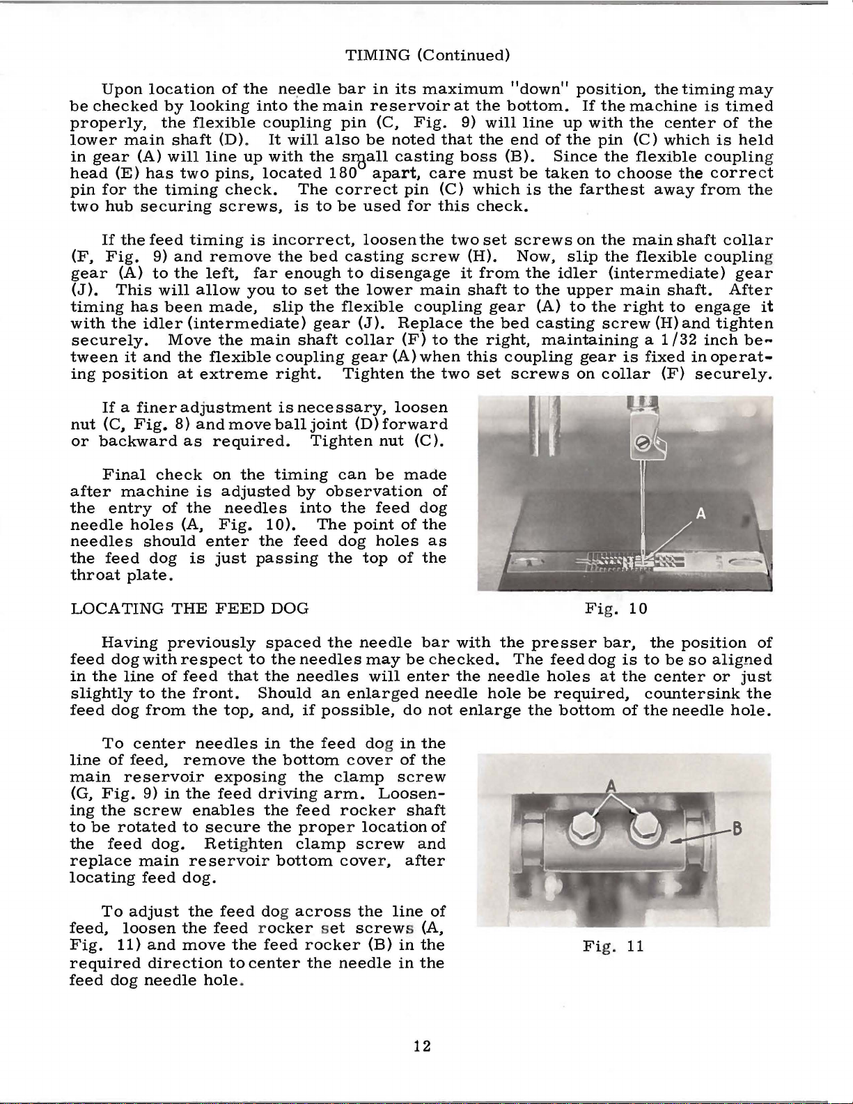
TIMING
Timing
shaft.
To
the
head
is
change
cover
the
synchronization
or
check
and
the
main
the
timing
gear
between
between
case
reservoir
the
the
upper
lower
bottom
main
and
shaft
upper
cover
Fig.
main
(Fig.
and
8
the
shafts,
9).
lower
remov
main
e
Make
position
needle
Timing
located
tween
certain
by
bar
on
flats
(by a visual
turning
connecting
between
the
lower
of
the
upper
the
handwheel
link
the
feed
align
needle
shaft
and
check)
in
perpendicular
bar
D,
lower
main
Fig.
that
operating
and
Fig.
9
the
the
feed
6)
is
shafts.
11
needle
behind
determined
bar
direction
lift
is
in
until
the
needle
eccentric
by
its
maximum
the
crank
bar.
(not
angular
"down"
pin
and
illustrated
relativity
the
but
be-
Page 12
TIMING
(Continued)
Upon
be
checked
properly,
lower
in
head
pin
two
(F,
gear
(J).
gear
(E)
for
hub
If
Fig.
This
main
the
(A)
timing
with
the
securely.
tween
ing
nut
or
it
position
If
a
(C,
backward
Final
after
the
machine
entry
needle
needles
the
feed
throat
plate.
location
by
the
shaft
(A)
will
has
the
timing
securing
feed
9)
and
to
the
will
has
been
idler
Move
and
finer
Fig.
8)
check
of
holes
should
dog
of
the ne.
looking
flexible
into
coupling
(D).
line
up
two
pins,
located
check.
screws,
timing
is
remove
left,
allow
far
you
made,
(intermediate)
the
main
the
flexible
at
extreme
adjustment
and
move
as
required.
on
the
is
adjusted
the
needles
(A,
Fig.
is
enter
just
the
passing
edle
the
main
It
will
with
the
The
is
to
incorrect,
the
bed
enough
to
set
slip
the
gear
shaft
coupling
right.
is
necessary,
ball
joint
Tighten
timing
by
into
10).
The
feed
bar
in
its
reservoir
pin
(C,
also
be
noted
s:sall
180
casting
apart,
correct
be
used
loosen
casting
to
disengage
the
lower
flexible
(J).
Replace
collar
gear
(F)
(A)
Tighten
loosen
(D)
forward
nut
can
be
observation
the
feed
point
dog
the
holes
top
of
of
maximum
Fig.
that
care
pin
(C)
for
this
the
two
screw
main
coupling
to
when
the
two
(C).
made
of
dog
the
as
the
at
9)
boss
(H).
it
shaft
the
the
this
"down"
the
bottom.
will
the
end
(B).
must
which
check.
set
from
gear
bed
right,
coupling
set
screws
position,
If
the
machine
line
up
with
the
of
the
pin
Since
be
taken
is
the
screws
Now,
the
to
the
(A)
casting
idler
to
farthest
on
the
slip
upper
to
the
screw
the
choose
the
(intermediate)
main
right
maintaining a 1/32
gear
on
is
collar
the
center
(C)
which
flexible
away
main
shaft
flexible
shaft.
to
(H)
fixed
(F)
timing
is
of
is
coupling
the
correct
from
collar
couplin
engage
and
tighten
inch
in
operat-
securely.
may
timed
the
held
the
gear
After
be
g
it
...
LOCATING
Having
feed
dog
with
in
the
line
slightly
feed
line
main
(G,
ing
to
be
the
replace
locating
feed,
Fig.
required
feed
dog
To
center
of
feed,
reservoir
Fig.
the
screw
rotated
feed
To
adjust
loosen
11)
dog
to
from
9)
main
feed
and
direction
needle
THE
previously
respect
of
feed
the
front.
the
needles
remove
in
the
enables
to
dog.
Retighten
reservoir
dog.
the
the
move
hole
FEED
DOG
spaced
to
the
needles
that
the
needles
Should
top,
the
exposing
feed
secure
and,
driving
in
the
bottom
the
the
if
the
feed
proper
clamp
bottom
feed dog
across
feed rocker set
the
feed
rocker
to
center
the
.
the
needle
may
will
an
enlarged
possible,
feed dog
cover
clamp
arm.
Loosen-
rocker
location
screw
cover,
the
screw
(B)
needle
bar
be
enter
do
in
the
of
the
screw
shaft
and
after
line
s (A,
in
the
in
the
with
checked.
the
needle
not
enlarge
of
of
the
The
needle
hole
be
the
presser
feed
holes
required,
bottom
Fi
dog
Fi
g.
bar,
at
g.
10
the
is
to
be
the
center
countersink
of
the
needle
11
position
so
aligned
or
hole.
8
of
just
the
12
Page 13

The
correct
timing between
the
hook
the
flat,
intended
operating
timing
the
hook
for
the
direction.
position
the
hook
screw
opening
flat on
of
opener
on
finger
the
the
the
hook
shaft
TIMING
hooks
finger
shaft
will
be
is
the
on
and
out
THE
their
flat.
of
first
HOOKS
shafts
the
If
time
one
hook
the
with
visible
is
of
is
governed
wrong
the
great
hook
hook.
as
the
importance.
by
the
position
screw
The
hook
is
timing
is
placed
screw
turned
The
of
on
in
The
while
back
obtain
Fig.
the
and
this
12
needle
needle
forth
condition.
and
the
guard
across
Fig.
hooks,
shortest
turn
the
Lock
in
Loosen
gears
shaft
(E,
without
Visually
spots
face
operating
the
needle
until
flush
time,
needle
lower
with
the
eye.
hook
is
just
the
needle.
12
illustrates
it
is
recommended
stitch
stitch
position
the
Fig.
check
their
direction
bar.
timing
the
hook
point
should
brushing
length.
regulator
by
tightening
two
6)
so
turning
position
respective
When
line
bottom
point
the
The
hook
accomplished
(C,
required.
shown).
the
stitch
the
regulator
To
do
this,
(B)
counterclockwise
lockscrew
screws
the
the
on
hooks
driving
of
each
will
gears.
the
hooks.
to
obtain a maximum
this
has
been
(of
the
pair
of
the
lower
should
be
approximately
needle
be
needle
approximately
(A)
guard
Adjustment
by
Fig.
6),
and
(Note:
regulator.
loosen
of
turn
needles.
Now,
reached,
selected)
needle
. 003
as
the
may
of
the
loosening
moving
Two
be
turned
lockscrew
as
(A).
the
freely
turn
"down"
bar
inch
hook
be
hooks,
the
screws
For
far
as
hook
shaft
with
Make
handwheel
continue
(B,
bushing.
1 I 32
apart
point
bent
right
the
saddle
hook
in
back
timing
to
produce
(A)
possible.
pinion
the
hook
sure
their
position
to
Fig.
7)
At
inch
above
(Fig.
is
rotated
slightly
or
left,
screws
saddles
are
the
and
in
of
turn
is
this
13)
to
is
as
not
When
positioned,
the
needle
its
properly
driven
gear
Whenever it
initial
the
in
timed
timing,
timing
paragraph
position.
the
bar
screw
Fig.
saddles
the
hooks
(B,
timed
(E,
Fig.
the
1.
13
and
their
may
be
Fig.
14).
position,
6).
is
necessary
hook
against
need
the
Automatically,
driving
timed
To
maintain
tighten
for a hook
only
flat
by
the
be
on
the
After
the
retaining
the
back
last)
should
directly
the
driving
tremely
and
minimum
gears
using
permanently
set
screws on
to
replaced
the
hook
hook
be
the
screws
the
hook
be
at
important
have
the
removed
on
shaft
retains
saddle
screws
shaft
centered
the
gear
been
timing
the
the
as
its
13
are
first
driving
on
gear
faces.
and
if
gear
correctly
marks
the
hook
hook
after
shaft
described
correctly
is
correctly
tightened,
and
the
the
the
maximum
sound
on
in
shaft
this
with
the
gear
hook
The
hook
are
located
(tightening
clamp
(F,
shaft
alignment
shaft
gear
to
be
Fig.
and
screws
Fi
g. 6)
looking
of
is
exlife
gained.
14
Page 14

SETTING
THE
FEED
DOG
HEIGHT
Place
approximate
above
of
travel.
Height
screw
bottom
To
make
screw
the
lever
1 I
16
inch
take
up
the
opener
screw
imately . 005
of
the
the
(G,
edge
Fig.
(B)
any
(C)
hook
the
throat
adjustment
this
on
to
setting.
and
basket.
throat
height
plate
Fig.
of
the
16
adjustment,
the
opener
the
proper
vertical
finger
move
inch
of
the
16)
in
feed
~
The
end
drive
the
away
Retighten
plate
(Fig.
is
finger
in
feed
15)
accomplished
the
feed
dog
rests.
dog
to
by
turning
wise.
screw
recti
on.
ADJUSTING
Place
Turn
finger
While
tightly
make
the
cam
loosen
lever
position
screw
play
that
shaft.
opener
from
the
the
dog
teeth
at
bar
the
To
in
the
is
at
in
this
against
this
surface
to
(D)
may
Now
finger
cam
screw.
machine.
is . 050
the
highest
by
on
which
Raise
desired
the
screw
lower
the
the
handwheel
adjustment.
the
and
obtain
is
it,
opposite
THE
opener
its
maximum
position,
the
on
clamp
swing
used
exist
loosen
approx-
surface
HOOK
the
point
turning
the
height
clock-
turn
finger
in
hook
the
to
in
The
inch
the
feed
the
di
...
OPENER
the
point
the
opener
basket
The
basket
FINGER
(A,
Fig.
operating
of
travel
finger
(E).
opener
for a length
Fig.
17)
direction
should
Loosen
finger
15
in
from
should
the
machine.
until
the
be
screw
of
1 I
needle.
moved
(C)
contact
16
inch.
the
to
ADJUSTING
Fig.
18
THE
FOOT
ulator
machine
amount
presser
thumbscrew
sure,
to
foot
to
the
plate.
The
while
feed
With
should
118
inch
presser
PRESSURE
presser
(B.
Fig.
head,
of
pressure
foot.
in
clockwise
the
work
the
hand
rest
should
bar
spring
18)
controls
Turning
counterclockwise
uniformly
lifter
securely
be
connection
reg-
atop
maintained
the
the
on
the
the
turning
is
in
down
on
as
required.
the
14
direction
increases
position
throat
between
the
presser
it.
(A,
plate.
the
Fig.
foot
17
decreases
Only
presser
enough
Fig.
18)
Approximately
rests
the
bar
on
foot
pressure
presser
guide
the
throat
pres-
1116
and
Page 15

CHECK
The
the
needle
stop
is
Loosen
locknut
position
for
first
barrel
1 I 8
inch
thread
SPRING
take-up
thread
at
the 9 o•
screw
(D)
to
for
the
sewing
should
movement
passes
ADJUSTMENT
spring
barrel
should
(C)
make
barrel
clock
and
position
turn
this
adjustment.
should
trials.
be
adjusted
of
the
around
the
(A,
Fig.
be
set
so
as
barrel
(A)
be
Ultimately,
so
that
check
spring
6 o1clock
19),
which
that
the
lower
shown
(B,
immediately
This
recommended
approximately
the
take-up
there
is
(E)
position
about
as
of
controls
spring
Fig.
behind
correct
spring
1/16
the
needle
the
19).
to
hook.
Test
tension
raised
(F)
and
may
4 o1 clock
ment
of
to
with
will
is
no
pressure,
above
locknut
depend
fabric.
Machine
age,
feed
on
tack,
and
circle
off
check
to
insure
released.
be
position
made
suggested
Fig.
tack,
at
material
spring
set
so
from
(D).
upon
20
should
all
tension
a
good
that
for
the
and
turning
position.
Final
weight
POSITIONING
position
ADJUSTMENT
thread
spring
Fig.
Fig.
sew
in
line
speeds.
without
(E).
returning
The
take-up
the
head
first
take-up
sewing
pressure
the
check
and
Set
spring
type
the
parallel
By
sewing
tension
pressure,
19)
12)
continuously
of
feed
Styles
thread
There
snap
spring
slot
slants
trials.
screw
Maintain
pressure
of
thread
OF
front
FOR
trials,
(A,
and
set
to
required
without
tack,
and
622 00 L
breakage.
should
when
be
spring
adjusting
from
the
This
screw
(F)
position
counterclockwise
this
adjustment
adjustment
and
weight
THE
frame
with
FRONT
needle
the
cloth
CONTINUOUS
adjust
Fig.
position
the
stitch
the
20),
barrel
length
specifications.
thread
across
and
LA
the
must
enough
screw
10
adjust-
EYELET
thread
plate.
needle
check
break-
line
is
to
of
eyelet
SEWING
(A,
(B,
of
sew
(G,
Fig.
Fig.
19
19)in
its
lowest
SETTING
(FOR
The
on
the
loosening
(D)
right
The
maximum
release
The
the
tension
release
NOTE:
done
together,
release
THE
STYLES
tension
tension
screw
or
left
tension
travel.
sleeve
tension
discs.
arm
The
sleeve
NEEDLE
61800
release
release
(C)
as
release
forward
release
(B)
to
setting
because
will
TENSION
CA,
DA,
pin
arm
and
moving
required.
is
This
is
or
pin
This
the
rear
adjustment
of
if
the
still
not
RELEASE
HA,
62200
(A,
Fig.
(B).
This
the
Tighten
to
be
actuated
accomplished
backward
(A)
should
is
for
less
the
tension
tension
give
the
GA,
HA,
21)
should
adjustment
tension
screw
when
by
until
exert
made
proper
only
by
pressure
release
release
proper
arm
tension
KA
and
be
centered
is
made
release
the
presser
loosening
setting
enough
loosening
and
to
sleeve
is
and
too
release.
LA)
sleeve
screw
has
pressure
screw
the
front
the
far
15
by
foot
tension
back
is
(C)
been
(E)
for
any
Fig.
raised
and
rotating
attained.
to
release
and
moving
more
release
rotation
21
2/3
to
the
the
the
pressure.
arm
of
the
3/4
of
tension
thread
tension
should
tension
its
in
be
Page 16

16
Page 17

MAIN
FRAME
BUSHINGS,
COVERS,
PLATES
AND
HEAD
OILING
PARTS
Ref.
No.
1
2
3 57
4
5 57 WD
6
7
8
9
10
11
12
13
14
15
16
17
18
19
20
21
22·
23
24
24A
25
26
27
28
29
30
31
32
33
34
to
61
Part
No.
22564
62271
15438
22569
62282
62282
22569
62285
62285
62294
62282
22569
62282
61271
62271 G
62282
62282
62282
22569
22569
62290
62284
62292
62284
62294
22564
62251 E
B
F
WB
c
K
D
B
J
666-258
666-138
A
D
B
294
c
D
E
B
88
666-117
A
M
B
666-257
A
666-256
Screw,
Needle
Nipper
Needle
Screw,
Screw,
Head
Screw,
Needle
Needle
Oil
Oil
Top
Screw,
Top
Screw,
Screw,
Needle
Needle
Eyelet
Eyelet
Top
Top
Top
Screw,
Screw,
Main
Plug
Oil
Needle
Tension
Needle
Head
Oil
Oil
Screw,
Take-up
See
Cover----------------------------------------
Sound
61800
61800
Wick
Felt
Tube,
HA,KA,
Cover,
Cover
Cover
Cover,
Cover
Shaft
Screw,
Cup
H,
62200
Oil
HA,
Siphon
62200
Siphon
62200
62200
GA, HA,
following
Description
Needle
Thread
Plate---------------------------------------
Thread
Nipper
Head
Top
Bar
C, D, H,
Bar
CA, DA, HA,
------------------------------------------
------------------------------------------
Top
Top
Top
Thread
Thread
Mounting
Mounting
Top
Top
Thread
Nipper
Nipper
Plate--------------------------------
Cover---------------------------------
fusulator---------------------------------
Cover
Frame
62200
Frame
for
Styles
and
LA----------------------------------
hinged
Cover
Latch
Cover,
Hinge
right-----------------------------------
Gasket,
Cover,
Cover,
Bushing
-----------------------------------
Cover,
Lead-in
Lead-in
Sleeve,
Sleeve,
-----------------------------------
for
synchronizer
Nipper
Base--------------------------
Spring
and
Top
Pivot
Pivot
---------------------------------
Latch
right,
right,
right
right,
right,
---------------------------------
Pin
G, H, K
Pin
62200
61800
----------------------------
Eyelet,
Eyelet,
for
for
----------------------------
Base-------------------
------------------------
Cover
GA, HA,
CA, DA, HA,
for
for
Class
Class
for
for
Hinge--------------Bushings,
and
L-------------------
Bushings,
KA
Class
Class
Class
Class
mounting
61800
62200
for
Class
for
Class
61800-------------62200--------------
61800
62200
-------------------------------------------
Feed
Feed
62200
GA,
GA,
Take-up
GA, HA,
Rock
Release
G,H,K
Rock
Attraction
GA,
Intake
HA,
Intake
HA,
Shield,
KA
and
page
Shaft
Pin
and L ---------------------------Shaft
HA,
Tube,
KA
Felt,
KA
Shield,
KA
for
LA
Bushing,
Bushing,
Bushing,
Felt,
and
and
and
Styles
for
KA
and
LA----------------------
for
Styles
LA
--------------------------
for
Styles
LA
--------------------------
for
Styles
LA
--------------------------
61800
-------------------------------
right
for
left
Styles
61800
CA, DA,
Styles
61800
61800
61800
for
Styles
for
Styles
and
LA---------
62200
bracket
--------------61800
----------------
CA,
CA, DA,
CA, DA,
G,
A,
------------
-----------61800-------62200--------
------------
------------
C,
CA,
DA,
DA,
HA,
HA,
HA,
62200
holes
D,
HA,
Amt.
Req.
1
1
1
1
1
2
1
1
6
2
2
1
1
1
1
1
1
1
2
1
2
1
2
1
1
1
2
1
1
- 2
1
1
1
1
1
1
1
2
1
NOTE:
'~".
the
use
of
these
parts
are
recommended
17
when
sewing with
nylon
thread.
J
Page 18

18
Page 19

MAIN
FRAME
BUSHINGS,
COVERS,
PLATES
AND
HEAD
OILING
PARTS
Ref.
No.
to
33
1
34
35 61893
36 62294
37
38
40
41
42
43
44
45
46
47
48
49
50
51
52
53
54
55
56
57
58
59
60
61
Part
No.
62202
62202
62202
62202
62202
62202
62202
62202
62202
62202
62202
61893 A
56393
56393
660-356
22849
62236
50-568
22539
62232
61882
62232
62232
62232
25
62202
62202
62202
62202
62202
62202
62202
62202
62202
62202
62202
62202
62202
62232
62232
62202
62202
62202
62202
62282
62282
22569
G-98
G-97
G-96
G-94
G-92
G-90
G-88
G-86
G-84
G-80
G-76
c
G
A
c
D
B
F
D
A
c
F-125
F-124
F-123
F-122
F-121
F-120
F-119
F-117
F-115
F-113
F-111
F-107
F-103
c
A
N
T
R
s
G
F
c
Blk.
See
preceding
Bed
Slide,
Bed
Slide,
Bed
Slide,
Bed
Slide,
Bed
Slide,
Bed
Slide,
Bed
Slide,
Bed
Slide,
Bed
Slide,
Bed
Slide, rig
Bed
Slide,
Head
Oil
Screw,
Feed
Oil Sig
Plug
Lower
Shim
Lower
Lower
Screw,
Bed
Bed
Bed
Bed
Bed
Bed
Bed
Bed
Bed
Bed
Bed
Bed
Bed
Lower
Bed
Gasket,
Bottom
Screws,
Oil
62200
GA, HA, KA
62200
Class
62200
GA, HA,
Oil
Oil
Porex
Head
Tube
GA,
Rocker
ht
Screw,
Main
and
Main
Main
Lower
Slide,
Slide,
62200---------------------------------------
Slide,
Slide,
Slide,
Slide,
Slide,
Slide,
Slide,
Slide,
Slide,
Slide,
Slide,
Main
Lower
Slide,
except
Friction
Friction
Retaining
Cover
Description
page
right,
right,
right,
right,
right,
rignt,
right,
right,
right,
right,
Pump
Tube--------------------------------------Tube
Filter
Oil
Clamp,
Oil
Tube
HA,
Gauge
Oil
Main
Bed
Slide,
left,
left,
left,
left,
left,
left,
left,
left,
left,
left,
left,
left,
left,
Main
front,
Bottom
Bottom
for
No. 8
for
No. 12
for
No. 16
for
Nos.
for
Nos.
for
No. 40
for
No.
for
No. 56
for
No.
ht,
for
No. 80
for
No.
Assembly,
KA
and
Spring---------------------------------
-----------------------------------
Pump--------
for
Styles
and
LA
------------------------------
Clamp,
KA
and
Rock
Shaft
-------------------------------------
Feed
Rocker
Shaft
Shaft
Shaft
Shaft
Bushing,
Seal
Gasket
Bushing,
Bushing
Shaft
front,
for
No. 8
for
Class
for
No.
for
No.
for
No.
for
No.
for
No. 32
for
No.
for
No.
for
No.
for
No.
for
No. 80
for
No.
Bushing
Shaft
Style
Spring,
Slide,
Sprin
Cover-------------------------------
-------------------------------------Cover-------------------------------
for
all
62200 K
Bed
Bed
g,
Bushir.
Bed
gauge---------------------
gauge------gauge--------------------
20
and
24
gauges
28
and
32
gauges
gauge-----
48
gauge-------------------gauge-----
64
gauge-------------------gauge--------------------
96
gauge--------------------
for
Styles
LA
-------------~------------
-
-------------------------
61800
for
Styles
LA---------------------------
Bushing----------------------
Rock
Shaft
right
---------------------------inner
Sleeve,
Bushing------------------------
and
Attachments
gauge
61800
16
gauge
20
gauge
24
gauge---------------------
28
gauge--------------------gauge
40
gauge
48
gauge
56
gauge---------------------
64
gauge
gauge---------------------
96
gauge
Sleeve,
-----------------------
Styles
Slide,
Slide,
in
------------------------front
Slide,
61800
CA,
DA,
61800
Hole
--------------------right----------------
right---------------
Class
and
front
62200-----------
No. 12 g
---------------------
---------------------
---------------------
---------------------
---------------------
---------------------
--------------------left-----------------
Class
-----------------
------------------
front
----------------
-
------------
-----------
-----------
-
--------------
-
--------------
CA,
DA,
HA,
62200
CA, DA, HA,
-------------
------------auge
61800
and
Amt.
Req.
1
1
1
1
1
1
1
1
1
1
1
HA,
1
1
1
1
1
- - 1
1
3
1
1
1
1
1
1
1
2
1
1
1
1
1
1
1
1
1
1
1
1
1
1
1
1
1
1
1
1
1
11
NOTE:
these
parts
are
recommended
when
''A",
the
use
of
19
sewing
with
nylon
thread.
Page 20

20
Page 21

Re
f.
No.
l
2
3
4
5
6
7
8
9
10
11
12
13
14
15
16
17
18
19
20
21
22
23
24
25
26
27
28
29
30
31
32
33
34
35
36
37
38
39
40
41
42
43
44
45
46
47
48
49
50
51
52
53
54
55
55
A
56
57
58
59
60
61
62
63
64
65
66
67
68
69
70
71
72
NOTE:
Deta
Part
No .
62222
62291
22894
22884
22894
62252
666-137
22533
666-113
622
55
622
5 D
22596
622
51 A
622
51 c
89
622
51 B
660-208
6228
5 c
6228
5 E
6228
5
78
6228
5 A
22565
6228
95
62285
62217
22845
62218
22743
622 18 A
22798
622
71 K
62271
66
218
62218
62218
62218
29475
62284
62284
62283
6042
55235
22565
62284
95
62283
5523
5 E
6042
62283
29126
62283
62283
95
62245
28619
62245
62245
62245
62221
22894
62221
22894
62260
22894
62246
62283
62246
22882
62283
62283
22560
62283
62283
22570
531
il numb
UPPEH
A
c
A
AC
A
E
D
B
H
D
A
H
A
B
L
W-033
W-03
W-037
W-039
X
E
c
F
A
E
c
D
L
A
F
BP
A
J
A
B
c
c
G
A
F
F
D
A
B
G
E
A
H
c
A
er
MAIN
SIIAFT,
Upper
Main
Main
Shaft
Set
Screw,
Set
Screw,
Spot
Crank
Oil
Screw,
Oil
eedle
N
N
ee
Ta
Take-up
Scr
T a
Nee
Needle
N
ee
Needle
Screw,
Needle Bar
Scr
Needle
ee
N
Holding
N
eedle
Ho
Needle
Needle
5
Needle
Needle
Needle Holder
Needle
Needle
Feed
Feed
St1tch Regulating Stud
Locking Ball,
Stitch Reg
Locating Stud,
Locating Stud, Stit
Handwheel,
Thrust Col
Feed
St
itch
Pin,
S
titch Regulating Sha
Fe e d
eed Drtving Lever
F
Screw,
F
eed
Fe
32 a
nd
33
Screw,
Pin
Wick,
Take-up
Wick,
Bar
dle
Bar
Screw, Nee
ke-up
Lever Slee
Lever
ew,
Needle
ke-up
Lever
R
eta
ining
dle
Bar
Bar
dle
Bar
Screw, Nee
Bar
Needle
ew,
Needle
Bar
dle
Bar,
Screw,
Bar
lding Scr
Bar
Scr e w
Needle
Needle
Holder
Holder
Holder
Feed
N
eed
le
eed
le
N
Screw,
Washer,
Nut,
Screw,
Feed
Screw,
Driving Lever
Nut,
Washer,
Screw,
Driving Eccentric
Bearin
Eccentric,
Screw,
Screw,
Screw,
Driving Gear,
Set
Screw,
Regulating Shaft
Stitch Regu
Screw,
Driving
Feed
Driving Lever
ed
Driving Lever
Screw,
Screw,
are
includ
NEEDLE
Shaft
Crank
-------------------------
Crank
Needle
Driving
Connecting Stud
Bar
Ring,
Frame Rocking Link-------------------------Frame Rock
Frame
Frame
Bar
Frame
Bar
Frame
m arked "CW", for Class
Head, for gauge
ew Needle
He'ad,
----------------------------------------------------------------------Holder
Holder Eye
Washer,
Washer,
Washer,
Washer,
Rock
Feed
Feed
Needle
Needle Feed
Rock
Locking Collar
Feed
Driving Lever
Feed
Feed
g, F e
Stitch
ulating Stud
Stitch
#1
Vee
Handwheel
lar
--------------------------------------------
Thrust
Stitch
Lever Guide,
Driving Lever
Feed
Feed
ed wi
FEED
DRIVE
-----------
and
Counterweight
Main
Shaft
Main
Main
Pin
Lever
Bar
dle
Bar
ve
------------------------------------Frame
Stud
-------------------------------------------------
dle
Bar
Pivot
Frame
Guide
Frame
Rocking Link
Needle
for
Eyelet,
Shaft
Rock
Rock
Needle Feed
Needle
Shaft
Driving Lever
Driving Lever
ed
Driving Eccentric Ass
Feed
Feed
ch Regu
or
Collar
Feed
lating Shaft
Regulating Shaft
Driving Lever Guide,
Driving Lever
th
Crank -------------------------
Shaft
Crank
Shaft
Crank ---
---------------Stud
- - -
Connection
Link----------------------------
----------------------------------------Take-up
-----------------------------------------------
Regulating Stud,
upper
ft
Guide
Guide
Guide,
-----------------------------
Connection
-------------------Rocking Link
ing
Link
Frame
Pin
-------------------------------------------------------
Guide
and
Stud
Guide
Bar
Head,
40
s
-----------------------------,Wt-----
gauges 8 thru
for
let,
for
for
Class
for
Class
for
Class
for
Class
and
Lever
Shaft
-------------------------------------------------------
Shaft
Lev
Feed
Feed
Rock
Rock
Locking Collar-------------------
-------------------------------
Assembly
Driving Eccentric
Driving Eccentric
Locking Screw
-------------------------------------------------------------
Regulating Stud,
lating Stud,
Round
Belt
--------------------------------
--------------------------
---------------------------------------------------------
Driving Gear,
-------------------------------------------------------Connection-----------
Connection
lower
Sha
Guide
Link
upper--------------------
detail
number
AND
STITCH
D
es
-
-------------------------
- - -
---------------
-----------
---------------------
-
---------------
-------------------------
Lever
Pivot
thru
Nos . 12
gauge
Rock
Rock
Shaft
----------------------
ft
Pin
- - ---- -
Stud--------------------
Stud
--------------------
P i
n,
Stud
--------------------------------------------
Pin,
rear
Pin----------------
and
Stud
----------------
and
Pin,
for
62200, . 033
62200, • 035 inch thi
62200, . 037
62200, • 039
Assembly
er
Shaft
Shaft
----------------------------------------------
------------------------
-----------------------------
--------
Connection
--------------
-----------------Link
Guide, upper--------------------
-------------------------------------------
Stud
-------------------------------------------
front
62200
Class
96
(specify
32
(specify gauge)
and
Nos.
20
------------------------------------------------Lever---------------------------------------
Shaft
Lever
Lever
Lever----
embly--------------
Assembly,
-----------------------------------------
, f
or
Styles
for
Styles
for
Styles 61800
for
Styles 61800
upper
-----------------------
---------------
Pin
-------------upper-----------------
31
on
REGULATING
cription
--------
-----
-
---------front----------------
------,--------------
------------------------------------------
----------------------------------------62200
gauge)
16 gauges---------------------------------
thru
inch
inch
inch
----------------------------------------
-------------------------------------
-----------------------------------------
- -
----------------------------------
61800
61800
--
--------------
----------
-
---------------------------------------
ll
ga uges ex
- ---- - - - ---------------
------ - - -------
---
----------------
- -
--
-
-
---------------------------------
-----------------------------------
--------------------------------
-"'ff
32
--------------------------------
thick
ck
thick
thick
--
. 1
50
inch
C, D, H,
C,
D,
C, D, H,
CA,
-
------------------------------
--
----
----------------------------------
-----------------------------------
--
----------------
-
---------------------------------
--------------
cept
MECHANISM
--
- - - - - - - - -----------
----
----------------------
------- - --
- -
----
----------------------------
-
-------------------------
---------------------------
- -
------
-------------------------
----------------------------
-----------------------------
--
------------------------
-
---------------------------
~
'!t!L:·-
~'f'
----------------------
-----------------------
-----------------------
-----------------------
--
-------------------------
--
-----------------------------
--
-------------------------
--
throw
62200
H,
62200
62200
DA,
HA,
- -
------------------------
-
---------------------------
--
- - -
----------
-
----------------------
No.
--------
---------------
- -
-------------------
------
- - -
---------------
-
------------------
-
---------------------
-
---------------
---------------------
!l_
____________________
--------------------
- -
8 gauge.
-
----
--------------
----------------------
-------------------G, H, K
G,
H, K
G, H, K
62200 GA,
---------------------
-
-------------------
-
--
- - -
------------------
- - -
-------------
- - -
-----------
-
--------------
--------------
and L -----
and L -----
and
L - -
HA, KA,
---------------
-----------
--------------
- - - -
- -
---
---
as
as
as
as
-
-----
-----
---
- - - 1
- 1
- 1
- 1
- - 1
- 1
---
-
required
required
requ
requir
---2
--
- 1
- 1
-
---
---1
---2
----
LA-
- 1
-
---
---1
---1
---2
---1
Amt.
R
1
1
3
1
1
1
1
1
1
1
1
1
1
1
1
1
1
1
1
1
1
1
1
2
1
1
1
1
ir ed
ed
1
1
1
1
1
1
2
1
1
1
1
1
1
1
1
1
1
1
2
2
1
2
1
1
1
1
1
1
1
q.
21
Page 22

~
/
-
~
32
18
22
Page 23

LOWER
FEED
DRIVING
AND
HOOK
DRIVING
PARTS
Ref.
No.
1
2
3
4
5
6
7
8
9
10
11
12
13
14
15
16
17
18
19
20
21
22
23
24
25
26
27
28
29
30
31
32
33
34
35
36
37
38
39
40
41
42
43
.
44
'!!5
46
47
48
49·
50
51
52
53
-
Part
No.
62243
62232
22706
62243
62243
22839
62238
29126
62238
62206
22894
22894
51147
62260
22894
62260
62282
62282
22569
22597
62262
62261
61264
HA61 D
9663
22775
62234
62236
62236
22866
.
63435
22706
62236
62236
55235
6042
55235
51241
22729
HS35 E
51239
22729
51242
A
s
25
G
A
E
c
A
A
BL
c
D
KH
22
95
H
F
G
J
H
c
A
A
A
89
D
95
G
666-115
A
A
A
F
D
A
E
18
D
c
269
18
L
c
M
18
Hook
Screw,
Feed
Screw,
Hook
Hook
Feed
Feed
Screw,
Collar,
Lower
Main
Gasket,
Lower
Screw,
Set
Intermediate
Intermediate
Collar,
Feed
Screw,
Screw,
Feed
Collar,
Feed
Oil
Feed
Screw,
Feed
Feed
Nut,
Ball
Nut,
Feed
Nut,
Ball
Washer,
Nut,
Shaft
Driving
Shaft
Shaft
Screw,
Lift
Lift
Feed
Feed
Screw,
Set
Shaft
Screw,
Screw,
Dog
Bar
Screw
Screw,
Rocker
Screw,
Wick-----------------------------------------------
Bar
Rocker
Rocker
Locking
Washer,
Nut,
Ball
Joint
Screw,
Feed
Driving
Feed
Joint
Screw,
Ball
Driving
Hook
Feed
Feed
Lower
Main
Screw,
Main
Lower
Intermediate
Feed
Feed
Feed
Feed
Shaft
Shaft--------------------------------------
Driving
Driving
Driving
Hook
Eccentric
Eccentric
Lift
Lift
Set
Screw,
Spot
Screw,
Lift
Collar,
Shaft
Driving
Lower
Shaft
Intermediate
Gear
Gear--------------------------------------
Collar,
(See
Dog
Dog
----------------------------------------------
--------------------------------------------Rocker
Collar,
-------------------------------------------
Feed
Shaft
Rocker
Rock
Rock
Stud,
Driving
Driving
Joint
Feed
Ball
Driving
Connecting
Driving
Feed
Ball
Ball
Joint
Joint
Gear
Driving
Gear,
Gear,
Shaft
Link
Assembly
Eccentric
Eccentric---------------------------------
Feed
Eccentric
Main
Lower
Driving
Coupling
Gear---------------------------------
Main
Hole
Main
Pages
Feed
Feed
Shaft
Shaft
Intermediate
---------------------------------------
Height
Feed
Rocker
----------------------------------------Shaft---------------------------------
Shaft
Driving
Arm
Driving
Joint
Connecting
Connecting Rod------------------------
Driving
Joint
Feed
Description
Guard---------------------------
Gear
Shaft-------------------------------
for
for
Driving
Pin
Bearing
Lift
Feed
Shaft--------------------------------
Shaft
Gear
29,
Rock
Rock
Arm-------------------------------
Driving
Driving
Lift
Gear
-------------------------------Hole
Cover
Hole
Gear
--------------------------------Shaft--------------------------
31,
Adjustment----------------------
Shaft--------------------------
Rocker
--------------------------------
Shaft
Driving
Arm
---------------------------------Connection,
Connection-------------------------
Rod
Connection,
Connection-------------------------
Driving
Guard--------------------
Class
Class
----------------------------
Eccentric
Link
Main
Plate-----------------------
Cover
Shaft-----------------------
33)
Connection,
Rod------------------------
----------------------------
Connection,
62200
61800
Gear----------------------
---------------------------
-------------------------
Eccentric
Pin
Shaft
Coupling
Cover
Gear
-------------------------
Rock
-------------------------Arm
--------------------------
lower
upper-----------------
Connection,
-----------------
-----------------
------------------
-----------------
---------------------
--------------------
------------------
Plate
Plate----------------
Shaft---------------
Shaft---------------
---------------------
---------------
lower------------
----------------
upper------------
upper
--------
Am
Re
1
2
1
1
2
1
2
1
1
1
1
1
1
1
3
2
1
2
1
1
1
3
1
1
1
1
2
1
1
1
1
1
2
2
1
2
2
1
2
1
1
1
1
1
1
1
2
1
1
1
1
2
1
1
t.
q.
23
Page 24

61
~
24
~
24
Page 25

P
HESSEH
BAH, FOOT
LIFT
AND
TENSION
HELEASE
PAHTS
He f.
No
1
2
3
4
5
6
7
8
9
10
11
12
13
14
15
16
17
18
19
20
21
22
23
24
25
27
28
28
29
30
30
31
32
33
34
35
35
36
37
38
39
40
41
42
43
45
46
47
48
49
50
51
53
54
55
56
57
58
59
60
61
62
63
64
65
.
A
A
A
t
e
fl
"·
Q
.,.
G
0
Part
61257
61256
62256
62268
62292
22894
61248
61248
62268
62292
2258
62292
62268
22884
62268
62268
62268
11635
22817
22712
9937
2287
61292
61392
61292
61492
62292
62292
.
5129 2 A
51
62292
62292
62292
62292
51235
62292
62292
22760
62292
22569
29475
22562
62253
62253
62253
62253
6225
62253
62253
62271
62259
61265
22799
22758
62268
62258
62257
22726
22569
No,
G
G
A
K
w
H
II
88
v
88
D
c
\V
H
660-142
J
660-142
F
G
B
c
A
4
c
F-9
H
H
109
j)
s
u
292
D
294
J
c
T
p
G
L
N
R.
c
AL
H
E
K
L
3 D
J
F
c
77Q
93
A
M
B
E
A
L
F
~
~
Description
Presser
Washer,
Presser
Presser
Tension
Stitch
L
Stitch
Presser
Tension
and
Screw,
Tension
Presser
Cotter
Presser
Cotter
Presser
Presser
Nut,
Screw
Screw:
Lock
Adjusting
Tension
Needle
Tension
Tension
and
Tension
Tension
Tension
Tension
Tension
Screw,
and L --------------------------------------------------------
Tension
Tension
Tension
LA--------------------------------------------------------
Spacing
Spacer
andL--------------------------------------------------------Tension
Tension
Screw,
L
Tension
L
Screw,
Check
Needle
P
resser
Hand Lif
Screw,
Screw,
Presser
P
resser
P
resser
Screw,
P
resser
S
crew,
Throat
Spring
Spring
Foot
Release
Screw,
Hegulator
--------------
Hegulator
I<A
LA
Screw,
Foot
Helease
LA
Screw,
Tension
Helease
and
LA
Screw,
Pin,
Foot
Pin,
Foot
Foot
Presser
Presser
Presser
Nut,
Post
Thread
Release
Release
LA
Disc---------Post
Post:
Post
Post
Tension
Post
Release
Release
Sleeve,
Washer,
Disc
Release
Tension
---------------------------------------------
Disc
----------------------------------------------------------------
Needle
Spring
Screw,
Barrel
Thread
Lock
Check
Check
Screw
Mounting
Thread
Bar
Screw ---------------Screw
ter--------Hand
Pr e
Foot
Bar
Bar------------
Presser
Foot
Throat
Pla
Heg
ulator
and
Presser
-----------------------------
-----------------------------------
---------
Foot
Presser
Screw,
-----------------------------------------------------------
Nut-------------------------------------------------------
Bar
Bushing,
------
Lifter
Tension
Stitch Reg
Lifter Shaft----------
Tension
Lifter
Presser
upper,
Lifter
lower,
Lifter
Lifter
Foot
Nut
Tension
for
for
Ferrule-----------------------------------------------Thread
Bracket,
Lifter,
Lifter
Thread
Assembly
Thread
Clamp
Eyelet
- - - - - ---- -
Shaft
Arm,
Shaft
Shaft
Sleeve,
Release
Arm,
Foot Lifter
Foot
Presser
---------------------------------------------------
Washer,
Washer,
Styles
Styles
Spring----------------------------------
for
Styles
Helease
-
--------------------
Helease
--
- -
Lever-------------------------------------------
Foot
Presser
Rod---------------------------------------------
Presser
Lever
Lever
Lifter
Arm-------------------------------------
Collar,
Collar,
ulator
for
for
Shaft Collar
for
Styles
Sleeve-----------
Arm
----------------------------------------
for
Styles
-----------Lift
er
Foot
Foot
Bell
Bell
Lever
Lever
Lifter
Lifter
Foot
Lever
Lever
Lifter
Foot
Spring--------------------------
for
Styles
for
Styles
-
---------------------------------------------
61800
C D H
61800
CA,
Eyelet------------------------------------------
Post
Pin,
Pin,
for
Styles
Spacing
Pin,
Disc
Spring,
Eyelet
Bracket,
for
for
for
for
for
Lifter,
Guide
for
Styles
Styles
Styles
61
BOO
Sleeve,
Styles
61800
Styles
for
for
----------------------------------------
-----------------------------------------
--------------------------------------
--------------------------------------------------
---------------------
Presser
Bar
upper---------------------------------
----
- - -
------------------------------
61800
Styles
Styles
61800
, D,
61800
61800
-
------------------------------
-
---------------------------------
61800
CA,
CA, DA,
-
---------
Lever---------------------
Lifter
Hod - -
Lifter
Crank -------------------------------Crank
Bell
Hod
Roller
Crank
Bell
Crank--------------------------
Bell
Crank
Bell
Lever
61800
61800
62200
DA,
HA,
Styles
61800
61800
C,
61800
C,
D,
H,
Styles
CA,
D, H,
62200
61800
C,
for
C, D,
61800
c. D,
Styles
61800
Styles
61800
Spring Barrel--------------------------------------------Spring ---------------------------------------------------
Stud
--------------------------------------------------
Plate-----------------
Guide------------------
Guide---------
----------------------------------
-
-
------------------------------------
-
-----------------
-----------------------------------------------
Lifter-----------
sser
Foot
Lifter
Connection
(See
te
(See
Lifter Link
Link
-------------
---------------------
Foot------------------------
Pa ges 29, 31, 35 )
Plate----------------------------------------
Pa ges 29, 3
-----------------------------
1,
-
--------------------------------
- -
-
---------------
-------------------
-
------------------------------
-------------------------------
33)------------
Bushing,
-- -
-----------------------------
Roller----------------------
Crank-----------------------
C, D,
CA,
D,
DA,
61800
JI,
H,
-
----------------------------
-----------
•
upper--------------
I-1,
62200
G,
H, K and L ------
C,
D,
II,
62200
-- --
----------------------
CA,
DA,
HA,
62200
DA,
HA,
62200
GA,
--
----------------------
--
- - --
------------------
HA,
62200
GA,
- - -
---------------------
-------------------------
---------------------------
--------------------------
Roller
-------------------
Bell
Crank-----------------
-
H,
DA,
G H K
62200
'GA, HA, KA
C,
D,
H,
62200
62200
HA,
G,
H, K
C, D, H,
62200
62200
C,
D,
H,
C,
D, H,
-
-----------------
-
--------------
- - -
-
-----------
-
------------
-
------------------
62200
HA,
H,
62200
G,
--------------------
-------------
G,
H, K and L ---
62200
and
L---------
62200
G,
H, K and L ------
G,
H, K and L -------
GA,
and L ------------
62200
H, K and L ------
G,
H, K and L -------
62200
G,
-
------------------
62200
G,
-
----------------
-
------------
-
-
---------
G,
H,
GA,
HA, KA
HA,
-
----------
GA,
HA,
and
LA
G,
H,
HA,
KA
-
G,
H, K
H, K a
H, K and
- -
---------
-
---------
-------
I<
I<A
K
------
nd
-
------
-
-
and
HA,
KA
-
----
----
-
and
-
----
-
----
- -
----
----
- -
--
---
---
if
-
- --
Amt.
Req.
1
1
1
1
1
1
2
1
1
1
1
1
1
r e
quir
- - 1
-
--
--
- -
--
-
--
- -
or
or
or
or
or
or
or
or
or
or
or
or
or
1
1
1
1
1
1
1
2
2
1
1
1
2
2
1
1
1
1
1
1
1
1
1
1
1
1
2
2
2
2
4
2
2
2
2
1
1
2
2
1
ed
1
2
1
1
1
1
1
1
1
1
1
1
1
1
1
1
1
1
1
2
1
1
1
1
1
2
1
25
Page 26

2
26
Page 27

HO
OK,
HOO
K DRIVING AND LUBRIC
ATING PARTS
Ref.
No.
1
2
3
4
5
6
7
8
9
10
11
12
13
14
15
16
17
18
19
20
21
22
23
24
25
26
27
28
29
30
31
32
33
34
35
36
37
38
39
40
41
42
43
44
45
46
47
48
49
50
51
52
53
54
55
Part
No.
29474
H
29474
62214
01
62208
62208
62210
62214
62214
62212
29480
62242
62241
62241 A
62242
62241 H
62241 G
62242
62244
62244
62240
62242
62241 c
62241 E
62241 B
62241 D
41355
62296 D
62296
62296
22585 G
22585
62241 F
22735
62242 B
12934
61451 c
62242
62296 B
62241
62241
62241
62241
61341 J
K
~~~
~
214 J
2716 F
71GE
A
c
72
22716 A
D
K
22716 G
B
2212
AT
29480
AU
A
22519
E
F
258 A
6042 A
820
G
A
98
D
U-8
A
c
907
T26
A
A
666-243
50-629
88
J87
157
Blk.
D
J
K-168
K-178
K-188
K-198
De
scription
Ve
rtical
L,
Vertical
Hook
Hook
•
Screw
Bobbin
Hook
Rest
Rest
Rest
Rest
\Vasher----~----------------------------------------------------1
Screw
Hook Asse
GA,
KA
and
Hook
Bobbin
Hook,
Hook,
Screw
NeedleGuard
Screw
Bobbin
Bobbin
Screw-----------------------------------------------------Bobbin
Bobbin
Shaft
Shaft
Bobbin
Hook
Hook
\Vasher
Hook
Hook
Bobbin
Gasket,
Gasket,
Bottom
Bottom
Shim, • 008
Hook
Oil
Lock
Nut
Screw
Screw------------------------------------------------------
Oil
Screw
Screw
Bobbin
Nut
\Vasher----------------------------------------------------Oil
Oil
Screw
Shaft
Plate,
Plate,
Plate,
Plate,
Case
Latch
Latch
Thread
Screw
Screw--------------------------------------------------
for
for
-----------------------------------------------------
-----------------------------------------------------Case
Case
Brake
-----------------------------------------------------
Mounting
Mounting
Case
Screw
Shaft
Shaft
Bushing
Bushing,
Nut
Bushing,
\Vasher------------------------------------------------Screw
Bushing
Shaft
Screw
Shaft
Case
left-------------------------------------------------
right
Cover,
Cover,
Shaft
Flow
\Vasher
-------------------------------------------------------(not
Filter
------------------------------------------------------
------------------------------7----------------------- 1
Case
--------------------------------------------------------
Cup-------------------------------------
Sight
------------------------------------------------------
----------------------------------------------------------1
Case
Opener
Spiral
.168
.178
.188
.198
----------------------------------------------------------1
mbly,
LA
Assembly,
Assembly----------------------
Pressure
Spring
Tension
--------------------------------------------------
No.
29474 H assembly------------------------------
No.
29474 K assembly------------------------------
-----------------------------------------------
Retainer,
Retainer,
Spring,
Opener
---------------------------------------------Mounting
Mounting
-----------------------------------------------bronze
-------------------
bronze-----~-----------------------------------
--------------------------------------------------
------------------------------------------------
---------------------------------------------------Pinion--------------------------------------------
--------------------------------------------------
--------------------------
Opener
----------------------------------------------left
inch
Oil
Valve
Regulating
(not
used
Screen--------------------------------------------
Opener
Gauge------------------------------------------
Oil
inch
inch
inch
inch
for Styl
---------------------------------------------for
Pin
-------------------------------------------Spring-----------------------------------
for
Bracket
Bracket
Lever
Bracket
Bracket
----------------------------------------
Lever
------------------------------------------
right
-----------------------------------------
thick
-----------------------------------
-----------------------------------------
Screw------------------------------------
used
on
later
Lever
---------------------------------------------1
Feed----------------------------------------1
thick--------------------------------------thick--------------------------------------thick--------------------------------------thick
es
61800
Styles
-------------------------------------
marked
marked
and
and
61800
"B",
"C",
No.
29474 K assembly----------------
Oil
Oil
----------------------------------and
and
~
Link-------------------------------
on
later models)------------------------
models)
Shaft
for
No.
62241
C, D, CA, DA, 62200 G, K,
H, HA,
for
No.
for
No.
Reservd!r
Reservoir
Oil
Reservoir,
Oil
Reservoir,
Assembly,
Assembly,
-------------------------------
---~--
------------------------------
------------------------------
and
62241 A
62200
29474 H assembly--29474 K assembly---
Hand
-
----------------
left
right-----------
------------------
-
---------------
--------------
HA
left ---
right
------------
------
Amt.
Req.
1
----1 or
----
• 1
-
---
if
required
·
---or
or
or
1
or
1
or
1
or
1
or
or
or
or
1
1
1
1
1
1
1
1
2
1
2
1
1
2
1
1
1
1
1
1
1
1
1
1
1
1
1
1
1
1
2
1
1
1
1
1
1
1
1
1
1
1
5
1
2
1
1
1
1
1
1
2
2
2
2
2
2
2
2
2
2
2
27
Page 28

•
28
Page 29

PARTS
FOR
STYLES
IN
CLASS
61800
Ref.
No.
1
2
3
4
5
6
7
8
9
10
11
12
13
14
15
16
17
18
19
20
21
22
23
Part
No.
61871 A
187
A
61817
77 A
22726
61820
61830
61830
61330
61802
62202
61820
22797
61830
61830
61830
61830
22799
61830
61830
9663
61 805 A
61
22569
L
A
A
B-35
F-124
B
G
B
E
F
F
D
c
828
F
Description
Needle
andHA
Screw-------------------------------------------Needle
HA---------------------------------------------
Screw.
Presser
Bed
andHA
Bed
HA---------------------------------------------
Presser
Screw
Feed
Throat
HA---------------------------------------------
Screw
Bar
Eyelet.
-----------------------------------------
Bar.
Screw
for
Shank
Bottom-------------------------------------
Hinge
Slide.
Slide.
Screw
Shank.,
Shank.,
Plunger
Equalizer
Screw
Bottom
Bottom
-------------------------------------------
Do
Plate.
-------------------------------------------
for
--------------------------------------
presser
Foot.
--------------------------------------
Pin
right.
----------------------------------------left.
Foot.
-------------------------------------vertical
base
--------------------------------------
Section.,
Section.
g.
for
Styles
for
for
Styles
Styles
for
----------------------------------for
for
for
------------------------------------
-----------------------------------
Styles
61800
foot----------------------------
Styles
Styles
Styles
Styles
section
section--------------------------
right
left--------------------------
61800
61800
61800
c.
D.
H.
61800
61800
61800 D and
c.
H.
61800
c.
c. D.
-----------------------
------------------------
C.,
D.,
H.
C.,
D. H.
CA.
c. D.
CA.
CA
D.
H.
H.
DA
DA
CA.,
H.
CA.
DA
and
and
HA
CA.
DA
CA.
DA
------------
and
DA
and
DA
------
and
HA----
Amt.
Req.
1
1
1
1
1
1
1
1
1
1
1
1
2
1
1
2
1
1
1
1
1
1
1
2
29
Page 30

30
Page 31

ATTACHMENT
FOR
..
AND
STYLES
COMBINATION
62200 K .. L ..
KA
OF
and
SEWING
LA
PARTS
Re
No.
1
2
3
4
5
6
7
8
9
10
11
12
13
14
15
16
17
18
19
20
21
22
f.
Part
No.
23520
62220
61830
62230
62230
62228
62205
62220
62230
62230
62230
22569
22569
22757
62228
62205
21385
201 A
22508
21178
21177
1349
22647
A-12
N-12
H
D-41
L-12
L-12
M-12
T-12
D-41
F
F
E
K-12
K-12
B
A
A-5
K-24
De
scription
Taping
Presser
Attachment
Foot
..
for
..
for
Styles
Styles
62200
62200 K and
Shank-------------------------------------Spring----------------------------------
Hinge
Throat
Feed
Dog
Pin
PlatelJ
..
marked
-------------------------
for
St;;:les
' BD"lJ
62200 L and
for
Styles
LA-------------------------------------------
Presser
Foot,~~
for
Styles
62200 K and
Shank--------------------------------------
Presser
Hin
ge
ScrewlJ
ScrewlJ
Screw.~~
Throat
Feed
Tape
Tape
Throat
Throat
Throat
Plate,
Dog.~~
Reel
Reel
Foot
Bottom.~~
marked
Pin----------------------------------
PlatelJ
Plate
PlatelJ
for
for
Styles
Axle,~~
for
Bracket,
for
..
for
for
Styles
62200 K and
62200 K and
Styles
for
Styles
Styles
all
other
Styles
62200 K and
62200 K and
Screw--------------------------------------
Tape
Spring
Reel
Collar,
Disc,~~
for
for
Styles
Styles
62200 K and
62200 K and
Spring------------------------------------Thumb
Screw-------------------------------
Land
LA----------
LA---------
62200 L and
KA----------
"R"
-----------
62200 K and
styles----------
62200 K and
KA
----------
KA
------------KA
KA
KA----------
KA
-
--------
KA---KA----
--------
KA
--------
-----
-----
A
Req
-
--
- - 1
mt.
•
1
1
1
1
1
1
1
1
1
1
1
2
1
1
1
l
1
1
2
1
1
1
31
Page 32

32
Page 33

Minor
numbers
62205
F-16
aft
er
the
part
All feed dogs
to
explanation
aft
e r the
is
n feed dog
number.
have • 082 inch
below.
part
with
numbers
16/64
diamet
COMBINATIONS
indicate
or
e r needle hol
1/4
the
inch
es
gauge
between
except
OF
or
the
those
the
distan
needles.
whe re
SEWING
ce
The
the
between
gauge
number
PARTS
the
of
is
needles
"K"
numbers
preceded
in
64ths
of
is
shown
by a reference
an
inch.
in
Exampl
parentheses
mark.
Refer
e:
FEED
62205
62205
K67352
62205
+
REFERENCE
DOG
THROAT
A-8
A-12
(10)
H-i2
FEED
*
K68441
62228
62228
K67351
62228
DOG
(8)
NO. 1
PLATE,
A-8
A-12
(10)
A-12
REFERENCE
THROAT
TYPE
K68440
Flat
Flat
Flat
Flat
NO. 4
PLATE,
(8)
FEED
62205
62205
62205
62205
+
62205
+
62205
+
62205
*K67501
*K68375
*
K68444
TYPE
Tape
FULL
REFERENCE
DOG
Slot
F-12
F-16
F-20
F-24
H-16
H-20
H-24
( 12)
(20)
( 24)
HALF
THROAT
FEED
62228-12
62228-16
62228-20
62224-24
62228-16
62228-20
62224-24
K68439
62228-20
62224-24
FEED
*
NO, 2
PLATE,
(12)
FEED
62205 B-12
62205
62205
K6844
5 ( 12)
TYPE
Flat
Flat
Flat
Flat
Flat
Flat
Flat
Flat
Flat
Flat
REFERENCE
DOG
THROAT
B-16
B-20
FEEDDOG
62205-64
62205-80
62205-96
NO. 5
PLATE,
62228
B-12
62224
B-16
62224
B-20
62228 B-12
REFERENCE
THROAT
62224-64
62224-80
62224-96
TYPE
Tape
Tape Slot
Tape
Tape
NO. 3
PLATE,
Slot
Slot
Slot
TYPE
Flat
Flat
Flat
FEED
62205
62205
62205
62205
62205
62205
62205
FEED
62205
62205
62205
62205
62205
+62205
+62205
REFERENCE
DOG
D-32
D-40
D-48
D-28
D-32
D-40
D-48
REFERENCE
DOG
THROAT
C-28
C-32
C-40
C-48
C-56
G-28
G-32
THROAT
62224
62224
62224
62224
62224
62224
62224
62224
62224
62224
62224
62224
62224
62224
NO. 8
PLATE,
D-32
D-40
D-48
E-28
E-32
E-40
E-48
NO. 6
PL1\.TE,
C-28
C-32
C-40
C-48
C-56
C-28
C-32
TYPE
Raised
Rais
Rais
Tape
Tape
Tape Slot
Tape Slot
FULL
HAL
ed
ed
Slot
Slo
TYPE
Flat
Flat
Flat
Flat
Flat
Flat
Flat
t
QUARTER
F
QUARTER
FEED
FEED
62205
62205
62205
FEED
REFERENCE
DOG
C-64
C-80
C-96
FE
ED
62205
62205
*
Feed Dog ha
+
Fe
ed Dog has •
NO. 7
THROATPLAT
62224
C-64
62224
C-80
62224
C-96
RE
FERENCE NO.
DOG THR
D-56
D-64
OAT PLAT
62224
62224
s •
063 inch diamet
093 inch dia m e
E ,
D-56
D-6
TYPE
Flat
Flat
Flat
9
E , TYPE
4
R
aise
d
Ra
ise
d
er needle
ter
needle
hole
hol
e
33
Page 34

34
Page 35

PRESSER
FEET
REF.
NO.
2
3
4
5
6
7
8
9
10
11
12
PART
62220-12
62220-16
62220
62220
62220
62220
62220
62220
62220
62220
62220
62
220 D-12
6222
62220
62220
62220
62220
62220
62220
62220
62220
62220
62220
62220
62220
62220
62220
62220
62220
62220
62220
62220
62220
62220
62220
62220
62220
62220
62220
62220
62220
62220
62220
62220
62220
62220
62220
62220
62220
62220
62220
62220
K68360
NO.
A-8
A-12
A-16
A-20
A-24
A-28
A-32
C-12
C-16
0 D- 16
D-20
D-24
D-28
D-32
D-40
D-48
D-56
D-64
D-80
D-96
E-8
E-12
E-16
E-20
E-24
E-28
E-32
E-40
E-48
E-56
E-64
F-8
F-12
F-16
F-20
F-24
G-8
G-12
G-16
G-20
G-24
G-28
G-32
H-12
J-12
J-16
K-16
L-24
P-12
TYPE
Solid
Solid
Hinged 8
Hinged
Hinged 16
Hinged
Hin
Hinged
Hinged
Hinged 12
Hinged 16
Hi nged
Hi ng
Hinged
Hing
Hinged
Hinged
Hinged
Hinged
Hinged
Hinged
Hinged
Hinged
Hinged
Hinged
Hinged
Hinged
Hinged
Hinged
Hinged
Hinged
Hinged
Hinged
Hin
Hinged
Hinged
Hinged
Hinged
Hing
Hinged
Hinged
Hinged
Hinged
Hinged
Hinged
Hing
Solid
Solid
Solid
Hing
Solid
Hinged
Hinged--
ged
ed
ed
ged
ed
ed
ed
GAUGE
48
96
32
40
48
56
64
12
16
20
24
12
16
20
24
28
32
12
12
16
16
24
12
16
12
16
12
20
24
28
32
12
16
20
24
28
32
40
56
64
80
12
16
20
24
28
8
8
8
MARGIN
1/16
1/16
3/32
3/32
1/16
1/16
1/16
1/16
1/16
1/16
1/16
1/16
3/32
3/32
SHAN!
61830 62230
62230
62230
62230
62230
62230
62230
62230 F 62230
62230 F 62230
62230
62230 62230
62230
62230
62230 62230
62230 62230
62230
62230
62230 62230
62230
62230
62230
61830
62230
62230 62230
62230
62230
62230
62230
62230 62230
62230
62230
62230
61830
62230
62230 62230
62230
62230
61830
62230 F 62230
62230
62230 F 62230
62230 F 62230
62230 F 62230
62230 F 62230
62230
62230 v 62230
F
BOTTOM
62230
62230
62230
62230
62230
62230
62230
62230
62230
62230
62230
62230
62230
62230
62230
62230
62230
62230
62230
62230
62230
62230
62230
62230
62230
62230
62230
62230
62230
62230
A-8
A-12
A-16
A-20
A-24
A-28
A-32
G-12
G-16
K-12
K-16
K-20
K-24
K-28
K-32
K-40
K-48
K-56
K-64
K-80
K-96
L-8
L-12
L-16
L-20
L-24
L-28
L-32
L-40
L-48
L-56
L-64
M-8
M-12
M-16
M-20
M-24
N-8
N-12
N-16
N-20
N-24
N-28
N-32
S-16
U-12
HINGE
62230
62230
62230
62230
62230
62230
62230
62230
62230
62230
62230
62230
62230
62230
62230
62230
62230
62230
62230
61330
62230
62230
62230
62230
62230
62230
62230
62230
62230
62230
61330
62230
62230
62230
62230
61330
62230
62230
62230
62230
62230
62230
62230
PIN
D-41
D-41
D-41
D-41
D-41
D-41
D-41
D-41
D-41
D-41
D-41
D-41
D-41
D-41
D-41
D-41
D-41
D-41
D-41
B-29
D-41
D-41
D-41
D-41
D-41
D-41
D-41
D-41
D-41
D-41
B-29
D-41
D-41
D-41
D-41
B-35
D-41
D-41
D-41
D-41
D-41
D-41
D-41
TILTING
SPRING
62230 H 62230
62230 H 62230
62230
62230
62230
62230
62230
62230
62230
SPRING
GUIDE
62230
62230
H
62230
H
62230
H
62230
H
62230
H
62230
H
62230
H
62230
62230
62230
62230
SCREW
E-12
E-12
J
J
J
J
J 60 5 A
J
J
J
J
R
E-12
E-12
605
605
605
605
605
605
605
605
605
605
605
605
605
A
A
A
A
A
A
A
A
35
Page 36

A
ILLUSTRATION OF ASSEMBLY cr
KNEE PRESS AND
CLASS
A.
LOCATE
NAILS
BOARD.
IN
62200
DRIP
AT
INDENTATION MARKS
DRIP
PAN
MAo-liNES
PAN WITH
ON
FOUR
B.
LOCATE
ETS
HOLES IN BOARD.
KNEE PRESS
WITH
WOOD
BR~K
SCREWS
AT
36
Page 37

NUMERICAL
INDEX
OF
PART
S
Part
No.
18
...••.........•.
KH
22
25
25 s
T26
HS35 E •.•••••.••..•.
50-568
50-629
57
57
HA61 D
72
77 A .••.••••••••••
77
78
J87 J ..•..•......•.
88
88 D ..•.•••.••..•.
89
93
95
98
109
157
187 A ...•.•...•.••.
201 A
258 A
269
294
531
605
605 A
660-142
660-208
660-356
666-113
666-115 •.•••••••.••
666-117
666-137
666-138
666-243
666-256
666-257
666-258
820
907
1349
6042 A ••.•••••••••••
9663
9937 •••
11635 B ..•.••.•.•.•..
12934
15
438
21177 A •••..•••.•••••
21178
21385 B ••••••••••••••
22508
22519 E ..............
22533
22539 D ••••••••••.•••
22560 A ..•.••••••••••
22
562 .
22564
22
564 B . .
NOTE: Only
•.•...••..•.
c
..............
............
..•...••.•......
Blk
••.••••.
B1k
•...•.•.
WB
.....•....•.
WD
•.•.•••••••.
...•..•••••.•.
...........•..••
Q
•.•••.••••.••.
....••........•.
•.•.••....•.•.••
...••••.•••.•...
A
••••••••••••••
••••••.••......•
•..••.•..••.•.•.
.•••••...•.•....
.•••.•...•.•.•..
•.••..•••••.••
...••.••...•..
....•.•••.••..•.
...•••••••••••••
...••...••••..•.
•.•••••••.••.•••
••••••••••••••
.••.••.••.•.
••••••.••...
....••....•.
.•••.••.••
•.••.•.••.•.
•.••••••••••
•.••••••.••.
•••.••••••••
..•.••••••••
.....••.•••.
•..•••••.•..
..•••••••••••••.
.•••.•.•••••.•••
A-5
•••.••••••••
•••••••.••••••••
•.••.••••
A • •
•.•.••••••••
c
..............
••••••••••••••••
••••••••••••••••
•..••.•.•.•••.•.
.••••..•••
. .
••••••••••••••
••••••••.•.•
the bas ic part
available,
.
•.•
.
•.•.
r efe r
Pa
No
23
23
19
..
23
27
23
19
27
17
17
23
27
29
25
21
27
17,25
25,
21,
25
21,
27
25
27
29
31
27
23
17,25
21
35
35
25
21
19
. . 21
23
17
21
17
27
17
17
17
27
27
31
21,
23,29
25
25
27
17
31
31
31
31
27
21
19
21
25
17
17
ge
.
27
23
23
23,
numbers
to
the lis
Pa
rt
No .
22
565 B
22565
22569
22569
22569 D ..............
22569
22570
22585
22585
22585
22596 D ....••••......
22597 A ..............
22647
22706 A .••...•...•...
22712 A .•.....•.••••.
22716 A ..••.......•••
22716 E ..............
22716
22716
22726 L •.....•••••.••
22729
227 35 A
22743
227 57 E
227 58 B
22760
22775 A •.••......•..•
22797
22798 B .•.•.....•.•.•
22799 F •.•.•.•••.•.••
22799 M ••••••.•••..•
22817
22839 A ..••••••..•.••
22845 H •••.•..•••••••
22849 A ••••...••••••.
22866 G ...•..••••••..
22874
22882 B •••••..•••••••
22884
22884 A ..............
22894
22894 D .••••••••••..•
22894 F ..••••••••.•••
22894 G .•••••••••••••
22894
22894
23520
28619 ••••••••••••••••
27
29126
29126
29474 H •..•••••••
29474 K •••.•••••.••••
29475 X ••.•••••••••••
29475
29480
29480
41355
51147
5123
51239 L ••..•••••••.••
51241 D •••••.••••••••
5
1242 M ••••.•.••••••
5
1292 A ••..•.•.••••.•
5
1292 D •.•••.
tin
..............
c
..............
•.•.........•.•.
c
..............
F
.........••...
A
.••••..•••••••
......•....••...
c
..............
G
••••••••••••••
K-24
. •
F
..............
G
..............
c
..............
..••.••••••••.
...•.•.••...•...
..•.......••..
.•••••..••.••.
••.......•.••••.
..•.......•••..•
c
..............
.•.••••..••••.••
••...••••••••..•
c
..............
w
.....•.......
AC
••••••••••••
A-12
BL
•.••••••••••
BP,
••••••••••.•
AL
............
AT
.......
AU
............
U-8
.........
•••••.••••••••••
5 G
••••••••••••
are shown
gs
on pag
es
.••.••••.
.......
.
..
.
•••
.
....
.
..
. •
. •••..
in
indicated.
th
• • 25
inde
Page
No
.
21
21
17
19,
23,
17
25, 29,
21
27
25
27
21
23
31
23
25
27
27
27
27
25,
29
23
27
21
31
25
25
23
29
21
29
25
25
23
21
19
23
25
21
25
21
21,
23
23
21,
23
21
25
21
31
21
23
21
27
27
21
25
27
27
27
23
25
23
23
23
25
x. F
or var ious gauge s, cap
P ar t
No
55235 D ••...........•
55235 E ••...•........
56393
56393
25
31
61248
61256
61257
61264 A ...............
61265
61271
61292
61292
61330 B ..•••••...••.•.
61341 J ...............
61392
61451
61492
61802
61805 A ...............
61817
61820 A ...............
61820 B ••....•••••••.•
61828
61830
61830 A ••••.•.••••.•.•
61830 B ...............
61830
61830 D •••••... ~ ••...•
61830 E ..•..•••....•.•
61830 F .......
61830 G ...............
61871 A ...............
61882
61893
61893 A •••••••••••••••
62202 F •••••••••••••••
62202 G •••••••••••••••
62202 N •••••••••••••••
62202 R •••••••••••••••
62202
62202 T •••••••••••••••
622
62205 A •••••••••••••••
62205 B •••••••••••••••
62205
62205 D •••••••••••••••
62205 F •••••••••••
62205 G •••.•••.•••••••
62205 H ••••••••••
62205 K ••••.••••••••••
62205 L •••••.••••..•••
62206
62208 A ••••••••
62208
62210
62212
62212 B ........
62214
62214 D .••.••••••.•.••
62214 J .•..• •
62214 K •.••.••.••••.••
622
15 B .•••••••..•••
.
.•........
G
•••.•••..•..••
H
.••.•...•••....
G
•••••••••••••••
G
••••.•••••.•••.
.•.•.•.•..••...•.
••..•..•••.....••
..•••••...•••••
H
•••.•••.•••.•••
F
...............
c
...............
H
...............
•.......•••...•••
••••••.•.•.•...••
••••.•.•••••.••••
•.••••.••...•••••
c
...............
.................
•••....•..•......
s
...............
05.
• • • • • • • • • • • • • • • • 33
c
...............
•••••••.••••.••••
c
..........
•.•••••••••.•••••
•••.••...••..
••..••
• .
••••.••
•..••••
..
. • •
....
aciti
.
....•
......
.
..
.
•••
••••
••••
...
..
...
Pa
23
21, 23
19
19
25
25
25
23
25
17
25
25
29
27
25
27
25
29
29
29
29
29
29
29, 31 , 35
29
29
29
29
29
29
29
29
19
19
19
19,
19
19
19
19
19
33
33
33
33
33
33
33
31
31
23
27
27
27
• . 27
27
. • 27
27
.•
27
27
• • 27
s,
etc
g
No.
, 35
29
.
37
Page 38

NUMER
IC
AL
INDEX
OF
PARTS
Part
Page
No. No.
62215 c
62217 A ••••••••••••••••
62218 A •••••••••••.•••.
62218
62220
62220 A ••••••••••••••••
62220
62220 D ••••••••••••••••
62220 E ••••••••••••••••
62220 F •••••.••••••••••
62220 G ••••••••••••••••
62220 H •••••••••••.•.••
62220 J ............•...
62220 K ••••••••••••••••
62220 L ••••••••••••••••
62220 M ••••••..•••••••
62220 N •••••.••••••••••
62220 P ••••••••••••••••
62221 A ••••••••••••••••
62221
62222
62224
62224 B ••••••.••••.••••
62224
62224 D ••••••••••••••••
62224 E ••••••••••••••••
62224 F ••••••••••••••••
62228
62228 A ................
62228 B ••••••••••••••••
62228 K •......•...••.••
62228 L ••••••••••••••••
62230
62230 A ••••••••••••••••
62230 D ••••••••••••••••
62230 E ••••••••••••••••
·62230 F ••••••••••••••••
62230 G ••••••••••••••••
62230 H ••••••••••••••••
62230
62230 K ................
62230 L ••••••••••••••••
62230 M •••••••••••••••
62230 N •......•.••....•
62230 R ••••••••••••••••
62230
62230 T ••••••••••••••••
62230
62230
62232 A ••••••••••••••••
62232 B ••••••••••••••••
62232
62232 D ••••••••••••••••
62232 F ••••••••••••••••
62232 G ••••••••••••••••
62234
622
62236 A ••••••••••••••••
62236
62236 D ••••••••••••••••
62236 F .•••••••••••••••
62238
62238 A ••••••••••••••••
NOTE:
................
w
...............
••••.•••.••••••••
c
................
c
.................
••••••••••••••••••
•••••.••••.•.•••••
c
................
••••••••••••••••••
••••••••••••••••••
J
.••••••.••••••••
s
................
u
................
v
................
c
................
••••••••••••••••••
36 ••.•....•.•..••..•
c
................
••••••••••••••••••
Only
the
available,
basic
refer
27
21
21
21
35
35
35
35
35
35
35
35
35
35
35
31
31
35
21
21
21
33
33
33
33
33
33
33
33
33
31
31
31,
35
31,
35
35
35
31,
35
35
35
35
35
35
35
31
35
35
19
19
19
19
19
23
23
23
23
19
23
23
23
23
part
to
35
35
35
numbers
the
listings
Part
No.
62240
••••••••••••••••••
62241
.....•..•.........
62241 A ••••••••••••••••
62241 B ••••••••••••••••
62241
62241 D ••••••••••••••••
62241 E ••••••••••••••••
62241 F ••••••••••••••••
62241 G ••••••••••••••••
62241 H ••••••••••••••••
62241 K ••••••••••••••••
62242
62242 A ••••••••••••••••
62242 B ••••••••••••••••
62242
62242
62242
62243 A ••••••••••••••••
62243 E ••••••••••••••••
62244
62244 A ••••••••••••••••
62245
62245 A ••••••••••••••••
62245 B ••••••••••••••••
62245
62246
62246
62251 A ...........
62251 B ••••••••••••••••
62251
62251 E ••••••••••••••••
62252 A ••••••••••••••••
62253 D ••••••••••••••••
62253 E ................
62253 F ••••••••••••••••
62253 H ••••••••••••••••
62253 J ••••••••••••••••
62253 K ••••••••••••••••
62253 L ••••••••••••••••
62255 D ••••••••••••••••
62255 E ••••••••••••••••
62256
62257 A ................
62258
62259
62260
62260 G ••••••••••••••••
62260 H ••••••••••••••••
62261
62262
62268
62268 A ................
622
62268 F •••••••• ; •••••••
62268 G ••••••••••••••••
62268 H ••••••••••••••••
62268
62271
62271 F ••••••••••••••••
62271 G ••••••••••••••••
62271 K ••••••••••••••••
62271 L ••••••••••••••••
62282
62282 A ••••••••••••••••
are
c
................
••••••••••••••••••
D
••••••••••••••
F
••••••••••••••
G
••••••••••••••
••••••••••••••••••
..................
c
................
••••••••••••••••••
A
••••••••••••••••
c
................
..................
••••••••••••••••••
..................
••••••••••••••••••
................•.
..................
••••••••••••••••••
68 E ••••••••••••••••
J
.••.•••••••.•.•.
c
................
..................
shown
on pag
in
es
indicated.
the
.....
index.
Page
No.
27
27
27
27
27
27
27
27
27
27
27
27
27
27
27
27
27
23
23
27
27
21
21
21
21
21
21
21
21
21
17
21
25
25
25
25
25
25
25
21
21
25
25
25
25
21
23
23
23
23
25
25
25
25
25
25
25
25
17
17
21
21
17
17
For
various
Part
No. No.
62282 B ••••••••••....•
62282
62282 D •••••••••••••••
62282 E •••••••••••••••
62282 F .•••.••••••••••
62282 G ••••••.••••••••
62282 H ••••••••••••••.
62282
62282 K ••••••••.•.•••.
62283 A •••.•.........
62283
62283 D .•..•••.•.•••.•
62283 E •••..••.•..•.•
62283 F ..............
62283 G ••••..••.•.••..
62283 H ••.•••...•••...
62283 J ...............
62283 L ...•.....•....
62284 A •••••••••••••••
62284 B ••••••••.••••••
62284
62284 D •••••••••••••••
62284 E •••••••••••••••
62285
62285 A •••••••••••••••
62285 B •••••••••••••••
62285
62285 D •••••••••••••••
62285 E •••••••••••••••
62285 H •••••••••.•••••
62285 J ............•..
62290 B •••••••••••••••
62291 A •••••••••••••••
62292
62292 J .••••..••......
62292 K •••••••••••••••
62292 L •••••••••••••••
62292M
62292 N •••••••••••••••
62292 P •••••••••••••••
62292 R •••••••••••••••
62292
62292 T •••••••••••••••
62292
62292
62292
62294
62294 A •••••••••••••••
62294
62296 A •••••••••••••••
62296 B •••••••••••••••
622 9ti c
62296
63435 A ••..•.•.•.••..
K67351
K67352
K67501
K68360
K68375
K68439
K68440 •..
K68~41
K68444
K68445
gauges,
c
...............
J
••••••••.•••••.
c
..............
c
...............
•••••••••••••••••
c
...............
c
...............
••••••••••••••
s
...............
u
...............
v
...............
w
..............
•••••••••••••••••
c
..............
...............
D • •
•••••••••••••
•....•••••.••••.•
.•••••••••••••.•
••.•..••••..••••
••.•••••••••••••
••••••••••••••••
• .
•••••••••••..••
••.•..•••
•••••..•.••••.•••
••.•••.••••••••••
....•.......•..
capacities,
.
••••
etc.
. •
Pa
ge
17
17
17
17
19
19
23
23
17
21
21
21
21
21
21
21
21
21
17
17
21
21
21
21
21
17
21
21
21
21
17
17
21
25
25
25
25
17
25
25
25
25
25
25
25
25
17
17
19
27
27
27
27
23
33
33
33
35
33
33
33
33
33
33
38
Page 39

Union Special is offering two practical systems to help pinpoint and
redu
ce
your sewing machine maintenance costs: a record keeping
system to
and a part s inventory system to speed routine repairs.
Machine
up your maintenance
Union
record keeping system u
(Form
required, the card is
and their cost are entered in the spaces provided and the card is
The second system is
on repair costs
Request
233). When a machine requires service, the forelady
out the
fills in the
help spot machines requiring abnormally high maintenan c
Maintenance Records
ma
chines
or
Repair-prone
Special suggests
The first system utilizes a "Machine Maintenance Record" card
237)
for each sewing machine in a plant. When a repair is
pulled
...................
G
ill&
.,.
...
-.
is
Card"
top
desired. Two record cards are used: a "Repair
(Form
of
a "Repair Request Card" and gives rt to a mechanic. He
time
the repair
inexperienced competent operators
dollars in short order.
two
variations
si
ng cards provided by Union Special.
from
the file and the repair date, parts used,
MA
CH INE MAIN
.. I.NANCil
ft'I'LI
nNNl.UU
I
u•••
J
~·
~·'"'
-1-
fO\t~
.
et'\&11'
t'\ac:'l\l~
c:atd
\tec:OI
normally
234),
used when more detailed information
and a "Machine Repair Record"
work
is started, the parts used and their cost,
To
help spot these problems,
of
a simple maintenance
RECORD
•&
IUALMD
I I
l
'l'
..
-n
z31-
· tel\al\c:e
.oL
-1-
-
....
PART
USi
-
CI
AU~
IK:H
l:l
~
-.
..
-
........
or
foreman fills
refiled.
·
(Form
can
and the c
"
e,
to redu
eat
abnormally high maintenan
caused by routine repairs. To alleviate this situation, Union Special
recommends that manufa cturers establish a formal parts
system
be
needed parts. There is
for
down
when the overall savings are considered.
inventory
local Un ion Special Representative
ompl
Ma
chine Repair Rec
Whichever system is used, management now
Repair Part
While
Excessive machine downtime and
eliminated with an orderly in-plant inventory
spare parts. Long waits for deliveries are avoided and machine
For free sample
etion time. This data is then transferr ed to the pe
ord"
kept
in the offi ce.
ce
needless maintenance costs.
Inventories
rec
ord
keeping tells management which machines
for
each type
tim
e is
kept
MACWINE
REPAIR
M.llllllll
NAMI
II
AII
·
os:
I-
fO\t
1--
I="
t'\3c:'l\ll'
I--
lists for a variety
•
·
to a
~
ee
\t
cop1es
ce
, it does little to help reduce the
of sewing machine they operate.
no
longer a need to cannibalize other mac
minimum
RECORD
CAR
D
r.3F
l!l.."''"
1,'3'3-
l'a\t \tec:ot
of
the machine record cards and spare part
of
wa
sted hours by mechani
. The cost
::.:
w
!Xl.
l'
d c:atd ·
-I-
the most popular machines, contact
of
REPAIR REQUEST CARD
Du o
I
.
....
...
. ,
.........
I
'""""_
oo. ....
·~on
f
~.
=-
-_
-
fO\t~
~
el'alt
I INI:IU•
fiMICOMI'Lnr
Mll
Q UINICI NO--•M
or
write direct
ha
s an invaluable tool
of
the most c
a parts inventory is small
.
...
..
..
..
...,N
o.
.....
PA
RTS UU O
-·
-
'234-
.
\teque
-
Itla
D
D
---·
..
- ----
to
t c.atd -
s
-
~
--
--
Union
rman
requir
downt
inventory
ommo
1-
I
~
1-
I=
-·
1-
I=
1-
-
I=
I=
I=
I=
I=
I=
Special.
cs
e
can
hin
your
ent
ime
nly
e
Part
Number
61820
22726
61805
9663
22775
61828
22569
180
GXS
29474
72
62253
•
Style
______
ght
adjustment
Minimum
Per 5 Machines
Description
A
L
A
A
F
H
D
Presser
Feed
Throat
Needles
Vertical hook
Screw
Check spring
Screw
dog
Feed
Screw,
plate
Screw
foot
for
dog
feed
for
(specify
presser
screw
dog hei
throat
plate
size)
assembly
foot
Quantity
1
2
1
2
1
1
2
100
1
4
1
Part
Number
62253
61871A
187
77
62212
62214
22716F
22716E
J
87
62242
62212
....;::S;.;::
u""_
U!ated
Description
Lock
Needle
A
A
J
J
B
Screw
Screw
Bobbin
Bobbin thread
Screw
Screw
Screw
Bobb
Bobbin brake spr ing 2
61800
Minimum
nut
thread
in case opener
SP-are
holder
tension
CA
Parts
List*
Minimum
Per 5 Machines
eye l
et
spring 1
Quantity
1
2
1
4
2
1
1
1
1
"The
parts and
setting up the
can
only be established according to actual usage. The nature of the
sewing
operation
quant1t1es
initial
will
listed above are intended to assist you in
inventory
determine actual usage.
of
spare parts. An efficient inventory
Page 40

WORLD'S
FINEST
QUALITY
*
'6'
1'6
INDUSTRIAL
SEWING
MACHINES
UNION
SPECIAL
maintains sales
and
facilities throughout the world. These offices
aid
you
in
the selection of the right sewing
equipment for your particular operation. Union
Special representatives
tory trained
promptly
tion, there
serve you.
ATLANTA,
BOSTON, MASS.
CHICAGO,
DALLAS,
LOS ANGELES,
NEW
PHILADELPHIA, PA.
GA.
ILL.
TEXAS
YORK, N.
and
and
is
a Union Special Representative to
Check with
CAL.
Y.
efficiently. Whatever your loca-
are
and
service men
able
to serve your needs
him
today.
MONTREAL, CANADA
TORONTO, CANADA
BRUSSELS,
LEICESTER,
LONDON, ENGLAND
PARIS, FRANCE
STUnG
ART, GERMANY
service
will
are
fac-
BELGIUM
ENGLAND
Representatives
industrial
UNION SPECIAL
400
N.
FRANKLIN
and
cities
distributors
throughout
ST.,
In
all
Important
the
world.
CORPORATION
CHICAGO,
ILL.
60610
 Loading...