

Page 1
®
I
NDUSTRIAL
SE
WING
NE
ST
QUALITY
STYLES
61800 c
L E W I S • C 0 L U M B_ I A
MACHINES
61800 D
61800 H
62200G
62200H
No.
lOlL
T
hird
Edition
CLASSES
S
TREAMLIN
N
61800, 62200
EE
DLE FEED
LOCKSTITCH
•
.
ED
MACHI ES
CHICAGO
Page 2

Page 3
Catalog
INSTRUCTIONS
No.
FOR
101
L
ADJUSTING
Streamlined,
The
furnished
CLASSES
Vertical
61800
61800
parts
at
LIST
H
listed
list
D
AND
OF
61800,
Hook,
Styles
61800
in
prices
OPERATING
PARTS
62200
Needle
Feed,
c
62200
62200
this
for
catalog
repairs
Lockstitch
G
H
are
only.
Union
Rights
Third
Copyright
Special
Reserved
Edition
by
Machine
in
1960
All
Countries
MACHINE COMPANY
INDUSTRIAL
Printed
SEWING
CHICAGO
in
MACHINES
U.S.
A.
Co.
August,
1967
Page 4

Page 5
FOREWORD
The predominant
se
wing mac
needle
All
parts
A
few
1.
2.
3.
4.
hin
feed
are
of
the
STREAMLINED
Pleasing
and
taupe
SIMPLIFIED
Lubrication
oil
holes
FLEXIBLE
Maximum
lower
PERMANENT
After
hook
replaced
es
in
the
lockstitch
made
outstanding
ruggedness.
finish
main
the
shaft
to
in
appearance.
is
OILING
of
in
upper
COUPLING
gear
shaft.
hook
gear
without
idea
behind
world.
machines
precision
new
DESIGN
freedom
more
these
arm.
life
is
HOOK
has
been
retaining
further
~
The
new
are a decided
gauges
features
this
functional
from
restful
machines
produced
TIMING
to
(See
timed
screws
attention
is
high
speed.
achievement
insuring
are:
difficult-to-clean
the
eyes.
is
automatic
diagram.
by
the
according
secured,
to
complete
design
Fig.
flexible
to
setting
to
build
streamlined.
provides
with
1.)
factory
hook
and
the
along
interchangeability.
recesses;
the
exception
coupling
procedure.
may
timing.
best
vertical
these
greater
new
located
be
removed
industrial
hook.
lines.
stability
neutral
of
three
in
the
and
the
and
5.
RAPID
Precision
possible
It
is
our
enable
Specials.
Classes
Hand
adjustments
anxious
the
61800.
ADJUSTING
62200 G and H call
Union
to
ACCELERATION
methods
top
operating
constant
customers
The
Special
cooperate
following
62200.
INSTRUCTIONS
described
representatives
aim
to
procure
with
with
in
the
speed
to
furnish
pages
attention
use
of
you
to
manufacture
almost
concisely
all
possible
illustrate
for
MECHANICS
to
parts
illustrations.
will
be
plan
and
of
instantaneous.
prepared
advantages
and
describe
coveringthe
important
found
estimate
in
all
~
component
information
from
parts
to
meeting conditional
manufacturing
r e
quirement
parts
the
use
for
61800
s .
MACHJNECOMPANY
makes
that
will
of
Union
styles
C. D and
centers.
in
3
Eng
ineerin
g De
partment
Page 6
IDENTIFICATION
OF
MACHINES
Each
into
the
Union
name
Machines
contains
no
Standard
Standard
This
herein.
this
given
catalog
It
Class..
from
Where
catalog
by
a
letter
number.
appearance.
Each
it
appears.
Special
plate.
similar
letters.
machine
style
identification
applies
can
also
References
the
operator's
construction
A
symbol
part
nulilber
machine
in
Letters
style.
be
part
which
represents
is
identified
construction
suffixed
Letter
to
to
"Z",
specify
APPLICATION
specifically
applied
to
direction
position
to
with
such
while
IDENTIFYING
permits,
too
small
each
for
its
distinguishes
the
by a Style
are
designated
the
Class
however,
machine
OF
CATALOG
the
Standard
discretion
as
right,
seated
PARTS
Union
complete
it
same
part
number
is
reserved
is
to
some
left,
at
the
Special
catalog
from
regardless
number
by a Class
indicate
of
Special
style
of
Special
front,
machine.
part
is
stamping
another
of
which
is
number
the
individual
as a suffix
construction.
machine
machines
back,
stamped
is
identified
part
similar
catalog
stamped
which
to
as
listed
etc
.•
are
with
in
which
the
in
its
in
IMPORTANT!
STYLE
shipments
Post
cover
type
other
largest
between
represent
OF
Prices
shipments
the
Each
Union
number
details.
diameter
the
MACHINE
are
are
postage
shank
the
Selection
thread
used.
produce a good
ON
strictly
forwarded
are
insured
and
Special
denotes
The
size
of
and
complete
of
proper
Thread
stitch
ALL
ORDERS,
FOR
net
WHICH
cash
at
the
unless
insurance.
needle
the
kind
number,
the
blade
the
eye.
symbol.
r1eedle
should
formation.
PART
TERMS
and
are
buyer's
otherwise
NEEDLES
has
both a type
of a shank,
stamped
measured
Collectively,
size
pass
should
freely
PLEASE
IS
ORDERED.
subject
risk
directed.
number
point,
on
in
thousandths
be
through
INCLUDE
to
change
f.
o.
b.
shipping
and a size
length,
the
needle
type
number
determined
the
needle
PART
without
A
charge
groove,
shank,
of
an
and
by
NAME
notice.
point.
is
number.
finish,
denotes
inch
size
the
size
eye
in
AND
Parcel
made
midway
number
of
order
All
to
The
and
the
the
to
For
of
this
which
than
best
machine.
is
three-quarters
results,
backed
use
only
They
are
by a reputation
of a century.
genuine
packaged
for
producing
Union
under
4
Special
our
highest
needles
brand
quality
name,
needles
in
the ope
~
for
ration
more
Page 7
NEEDLES
(Continued)
TYPE
the
tremely
needle
A
036".
machines
is
NUMBERS
Two
standard
Each
To
have
or
complete
The
given
types
heavy
needle
Type
Size
the
covered
the
AND
of
needles
machines,
nature,
is
stocked
Number
Numb
orders
order
Type
description
Type
er
promptly
and
would
numbers
in
SIZES
needle
Size
this
are
use
by
The
finish
The
in
stamped
number
read
of
catalog
of
the
sold
for
needle
Type
Type
kind
largest
thousandths
and
as
the
needle:
Type
182
number
of
and
in
accurately
should
follows:
needles
are
use
180
GA
shank,
other
diameter
of
the
shank
filled,
be
"1000
listed
in
Classes
GL.
is
available.
and
Size
point,
details.
of
an
inch
of
the
given.
needles.
available
below.
For
number:
the
blade
across
each
empty
Use
for
Beside
61800
operations
length,
(measured
the
needle.
package, a sample
description
Type
use
and
groove,
eye)
180
in
the
Type
62200.
of
is
GL,
the
styles
For
an
ex-
on
label.
Size
number
of
Type
No.
180
GL
182
GA
ILLUSTRATIONS
The
accurate
Five
Each
position.
assembled
plate
Lockstitch.
point.
060,
Lockstitch.
chromium
arrangement
ordering
Exploded
presents
Small
machine.
chromium
067.
of
View
a
keyline
short
plated,
long
plated,
ORDERING
and
purpose
Union
plates
sector
views
Special
cover
Description
length,
length,
sizes -044, 048,
of
show
ball
eye,
sizes -032, 036, 040,
REPAIR
of
this
Machine
the
the
machine,
by
blackened
ball
eye,
catalog
Standard
single
single
054,
PARTS
Company
Styles
parts
area
groove,
060,
is
to
aligned
where
deep
044,
groove.
067.
facilitate
replacement
listed
in
in
parts
spot,
048,
deep
easy
parts.
this
catalog.
assembled
fit
in
ball
054,
spot,
and
the
Sub-assemblies
Each
ponent
Union
on
page
part
Special
facing
plate
available.
bears
Machine
illustration.
are
covered
respective
The
Company
reference
part
in
the
Exploded
description,
part
number
5
Views
numbers
the
used
by
and
arrows
amount
when
dotted
required
ordering
line
for
each
plus
is
boxes.
com-
the
found
Page 8
ILLUSTRATIONS
(Continued)
Component
indicated
assembly.
Ref.
No.
55
56
It
will
not
listed.
assembly
Basically,
single
the
is
and
61800
part
description.
needle
standard
changed.
complete
H,
Near
and
the
page
parts
by
indentation
Example:
Part
No.
51239
be
noted
Replacement
should
62200
be
Classes
while
machine
Special
lists
G,
back
numbers
of
L
97
A
in
the
ordered.
the
are
plates
of
sewing
62200
of
this
where
sub-assemblies
of
description
Feed
above
of
61800
Class
the
near
Driving
Joint,
these
and
same.
upper---------------------
Screw-----------------------
example
parts
62200
62200
the
parts
H.
catalog
is a numerical
components
which
underthe
Description
Connecting
that
is
not
are
the
is a two
In
some
back
of
this
applicable
are
can
be
furnished
descriptionfor
Ball
the
shell
recommended.
same
needle;
cases,
revised
to
shown
the
Styles
index
for
except
therefore,
of
accurate
for
and
the
Complete
Class
quantity
edition
61800 c.
parts.
repairs
the
main
Amt.
Req.
1
2
ball
stud
61800
all
parts
requirement
give
separate
61800
Listed
and
complete
ar
sub-
are
sub-
is
for
D,
are
e
a
STYLES
Streamlined
Needle
Stitch
anism,
Mechanism,
Mechanism,
Space
61800 C Single
61800 D Single
61800 H Single
62200 G Two
Feed
Regulator
One
to
medium
foot.
equipped
heavy
size.
shirts.
garments,
weight
Flat
and
ReservoirEnclosedAutomatic
Separate
Upper
Right
and
with
work.
Hinged
Needle
overalls,
jackets.
articles.
OF
Bed
Drop
with
Locking
Left
of
Needle
Needle
heavy
Needle
double
Needle
requiring
bottom
Machine for
work pants.
MACHINES
Lockstitch
Feed,
Reservoir
Head
Machine
weight
Machine
shop
Rotary
Device,
Mechanism
Bar
10
materials;
Machine
action
heavy
presser
coats,
IN
CLASSES
Machines.
Hook,
for
Inches.
for
miscellaneous
for
compensating presser
for
miscellaneous
thread.
foot.
miscellaneous
dungaree
aprons
Vertical
External
Lubricating
Automatic
Manually
equipped
top sti
16-4 cordis
and
Light,
Needle
tching
s ,
corsets
similar
61800
Lubrication
Lubricated,
seaming
with
seaming
AND
Medium
Hook
operations
Shaft,
Thread
System for
operations
hinged
waistbands
foot.
maximum
operations
and
light,
medium
62200
and Heavy
Thumb
Tension
Main Drivin
of Rotary Hoo
Maximum
bottom
to
on
m e
us
able thread
other
foundation
Duty,
Screw
Me
Wor
on
light,
presser
trousers;
dium
on
work
and heavy
ch-
g
k
k
and
62200 H Two
western
similar
usable
Needle
type
items
thread size.
dungarees.
requiring
Machine for
jackets,
the
use
miscellaneous
me
of
dium
heavy
6
weight
thread.
operation
canvas,
16-4 cor d is
s
on
overalls.
upholstery
maximum
and
Page 9
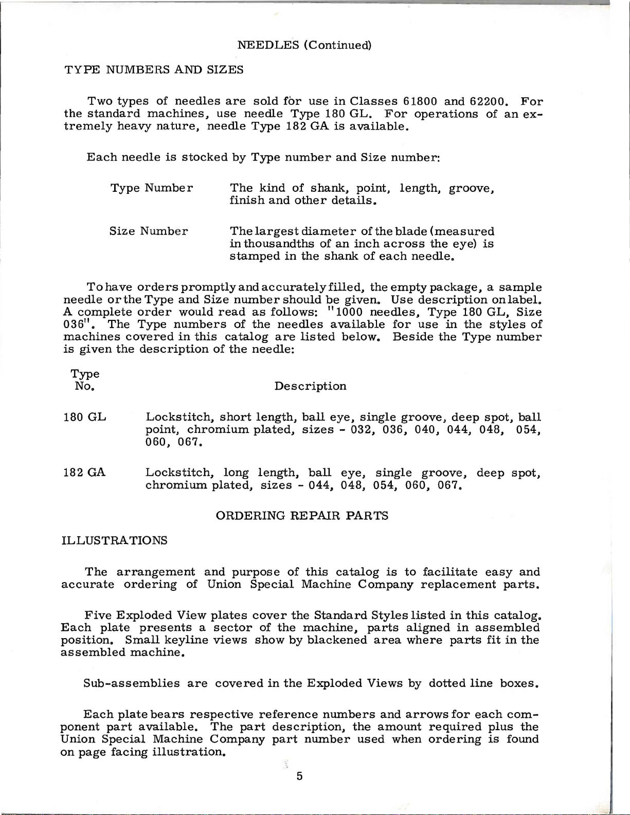
OILING
INSTRUCTIONS
There
62200
cups
are
machines
"C",
"D"
automatically
by a spiral
quired
metering
for
each
screw
reservoir.
the
gears,
feed
bearing
action
stitch
driving
etc.,
and
mechanism
The
level
servoirs
gauges
holes
can
"F"
"A",
mechanism,
and
needle
Use a straight
for
all
oiling
on
operating
lines
of
the
CAUTION!
the
machine
three
which
and
lubricated
oil
screw.
hook
located
The main
regulating
mechanism,
lubricates
also
supplies
through
of
the
readily
,·
"G''
and
"B"
and
the
left
bar
frame
mineral
places.
conditions,
sight
gauges
The
is
shipped
oil
reservoirs
are
"E"
(Fig.
from
The
may
reservoir
these
the
lower
oil
in
be
"H".
"J"
upper
pivot
Lubricate
main
and
filled
1).
its
amount
be
adjusted
at
the
mechanism,
upper
parts
oil
to
shaft.
the
three
observed
The
lubricate
main
pin,
oil
of a Say
and
add
"F",
"G"
reservoir
must
on
the
through
Each
own
the
hook
reservoir
of
oil
for
bottom
which
of
houses
needle
main
by a splash
the
lower
main
at
the
manually
the
shaft
bearing,
respectively.
bolt
machine
oil
to
cuos
and
"H
and
hook
be
filled
Class
oil
is
re-
by
a
the
shaft
feed
re-
lucite
oiled
head
viscosity
at
points
"C",
1
'.
reservoirs
before
of
200
"A",
"D"
and
starting
to
"B"
(or
250
and
"E"
reservoir)
to
operate.
Fig.
seconds
11
J"
twice
to
maintain
1
at
100 °
daily,
is
Fahrenheit
depending
levels
between
drained bef
ore
The
oiling
hook
reservoir.
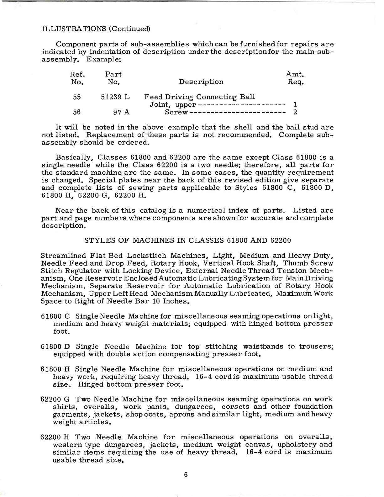
THREADING
Follow
needles
and
for
Class
THE
NEEDLES
instructions
associated
61800
in
threading
eyelets.
is
the
same
THREADING
diagrams
61800
as
for
Class
INSTRUCTIONS
(Figs. 2 and
62200,
3)
except
for
there
correct
is
threading
.
62200
only
one
of
Fig.
2
7
Fig.
3
Page 10
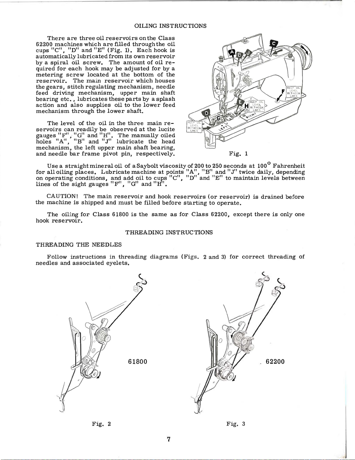
WINDING
THE
BOBBIN
Thread the
from
4),
down
tension
shaft
around
rection
until
belt,
chine
filled
out
member,
extent
by
the
The
from
wind
The
all
times.
one
and
while
the
supply
between
post.
(B)
up
the
bobbin a few
and
pulley
and
is
locked
is
operated,
until
the
to
which
regulating
tension
left
to
unevenly
purpose
When
begin
machine
bobbin
Press
to
the
press
is
moved
thread
which
the
post
right
may
to
is
winder
down
of
wind
through
the
tension
an
empty
stop,
downwardly
into
in
that
the
bobbin
engages
disengages
bobbin
screw
bracket
by
loosening
be
readily
the
bobbin
the
bobbin
the
sewing.
by
the
discs,
bobbin
wind
turns
contact
position.
will
the
is
filled
(D).
is
corrected.
winder
in
empty
leading the
eyelet
and
on
the
end
in a clockwise
on
hand
with
When
be
automatic
the
pulley.
can
mounted
screw
the
machine
bobbinimmediately.
thread
(A,
underthe
the
winder
of thr
lever
machine
the
rotated
throw-
be
varied
on
the
(E)
so
is
to
assure
Fig.
ead
di(C)
ma-
and
The
that
is
winder
any
the
used
Fig.
base,
tendency
operator a full
up,
Bobbins
and
replace
can
of
can
4
the
it
be
shifted
bobbin
bobbin
with a full
be
rewound
to
at
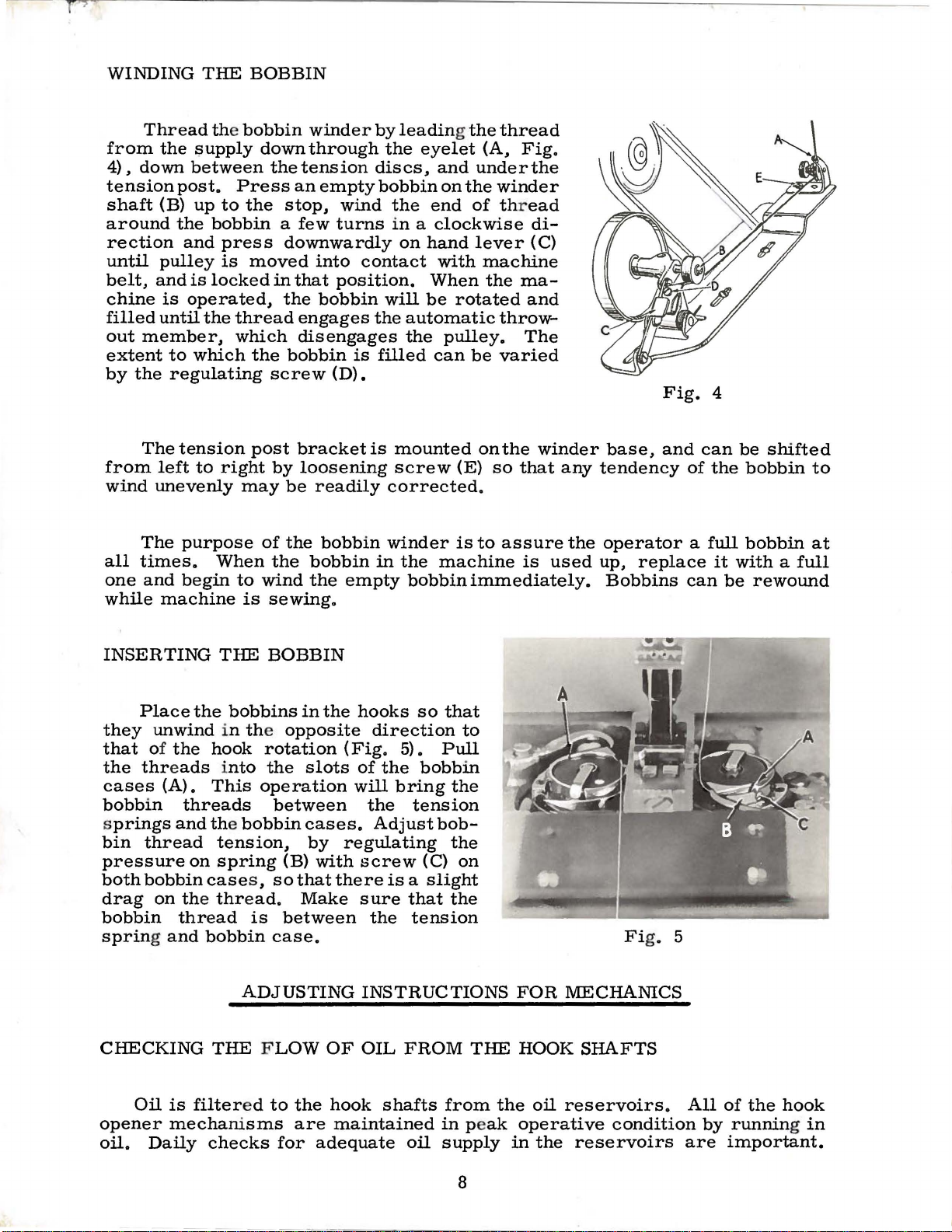
INSERTING
Place
they
that
the
threads into
cases
bobbin
s
prings
bin
thread
pressure
bothbobbincase
drag
bobbin
spring and
CHECKING
Oil
opener
oil.
the
unwind
of
the
hook
(A).
on the
Daily
This
threads
and the
on
thread
bobbin
THE FLOW
is
filter
mechanisms
checks
THE
tension,
spring
thread.
BOBBIN
bobbins
in the
opposite
rotation
the
operation
between
bobbin
(B)
s ,
sothatthereisa
is
between
case.
ADJUSTING
ed
to
for
in
the
slots
cases.
by
with
Make
OF
the
hook
are
maintained
adequate
hooks
(Fig.
of
will
the
regulating
screw
sure
the
INSTRUCTIONS
OIL
so
direction
5).
the
bobbin
bring
tension
Adjust
shafts
bob-
(C)
slight
that
tension
FROM
oil
that
Pull
the
the
on
the
from
in peak
supply
to
THE
FOR
HOOK
the
oil
operative
in
the
Fi
g. 5
MECHANICS
SHAFTS
reservoirs.
condition
reservoirs
All
by
are
of
the
hook
running in
important.
8
Page 11
CHECKING
THE
FLOW
OF
OIL
FROM
THE
HOOK
th
flowing
pins
a
normal
SHAFTS
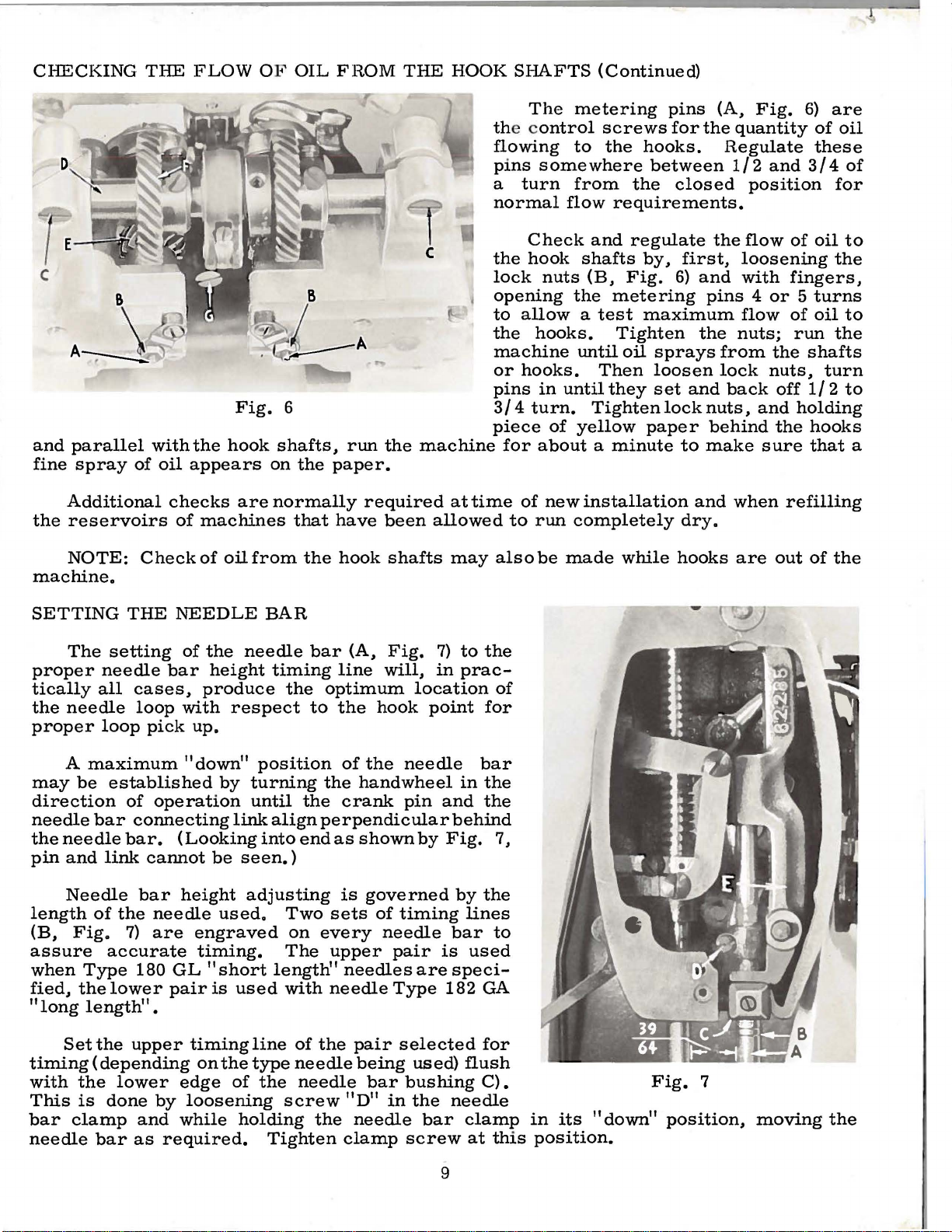
The
metering
e c
ontrol
to
somewhere
turn
from
flow
(Continued)
pins
screws
the
requirements.
for
hooks.
between
the
closed
(A,
the
quantity
Regulate
1/2
Fig.
position
6)
and
are
of
these
3/4
for
oil
of
and
parallel
fine
spray
Additional
the
reservoirs
NOTE:
machine.
SETTING
The
proper
tically
the
proper
needle
all
needle
loop
with
of
Check
THE
setting
cases,
loop
pick
the
oil
appears
checks
of
machines
of
NEEDLE
of
the
bar
height
produce
with
up.
Fig.
hook
are
oil
from
BAR
needle
respect
6
shafts,
on
the
paper.
normally
that
the
bar
timing
the
optimum
to
run
required
have
hook
(A,
line
the
the
been
shafts
Fig.
will,
hook
c
machine
at
time
allowed
may
7)
to
in
prac-
location
point
Check
the
hook
lock
opening
to
the
machine
or
pins
3/4
piece
the
for
nuts
allow a test
hooks.
hooks.
in
turn.
for
about a minute
of
to
run
also
be
of
and
shafts
(B,
the
until
Then
until
Tighten
of
yellow
new
installation
completely
made
regulate
by.
Fig.
metering
maximum
Tighten
oil
sprays
loosen
they
set
lock
paper
while
the
flow
first,
6)
and
to
dry.
hooks
loosening
and
with
pins 4 or 5 turns
flow
the
nuts;
from
lock
nuts,
behind
make
and
back
and
when
are
the
nuts,
off
the
sure
refilling
out
of
oil
to
the
fingers,
of
oil
to
run
the
shafts
turn
1/2
to
holding
hooks
that
of
the
a
A
maximum
may
be
direction
needle
the
needle
pin
and
Needle
length
(B,
Fig.
assure
when
fied,
"long
timing
with
This
bar
needle
Type
the
length"
Set
the
is
clamp
established
of
operation
bar
connecting
bar.
link
cannot
bar
of
the
needle
7)
are
accurate
180
GL
lower
the
(depending
lower
done
bar
pair
•
upper
by
and
as
required.
"down"
by
link
(Looking
be
seen.
height
used.
engraved
timing.
"short
is
used
timing
on
the
edge
while
of
loosening
holding
position
turning
until
adjusting
line
type
the
align
into
end
)
Two
on
The
length"
with
of
needle
the
needle
screw
Tighten
of
the
needle
the
handwheel
crank
perpendicular
as
is
sets
every
upper
needles
needle
the
pair
being
"D"
the
needle
clamp
pin
shown
governed
of
timing
needle
pair
Type
selected
used)
bar
bushing
in
the
screw
by
are
bar
in
and
behind
Fig.
by
lines
bar
is
used
speci-
182
flush
needle
clamp
at
9
bar
the
the
7,
the
to
GA
for
C).
this
in
its
position.
"down"
Fig.
7
position,
moving
the
Page 12

SETTING
To
to
the
bar
at
r e
move the top
right end
nut
(B, Fig.
(A}
and
F
ig.
of feed until
of
39/64
dle
bar
21227
adjustment.}
quired
8}
and
TIMING
THE
position
presser
the
of the
swing
7}
forward
inch
and
BLis
setting,
re-assemble
NEEDLE
the
needle
bar,
bottom
8}
the
is
the
availablefor
After
of
reservoir
machine.
of
the
the
needle
or
factory
obtained
presser
needle
tighten
BAR
bar
first
backward
cover.
set
its
stroke.
cover
Loosen
feed
driving
bar
specified
between
bar.
measuring
bar
clamp
(Continued}
in
relation
the
needle
Then,
at
clamp
lever
frame
in
(Gauge
meets
nut
(E,
the
line
distance
the
nee-
No.
this
re-
(B,
Fig.
the
Fig.
8
Timing
main
removetheheadcover
shaft.
To
is
change
the
or
synchronization
check
the
andthe
timing
maingearcase
between
between
the
upper
the
reservoirbottom
main
lower
and
shaft
upper
and
main
cover
the
shafts,
(Fig.
lower
9}.
F ig. 9
Make certain
"down" positi
pin
and the needle bar connecting
Timin
butlocated
fl
ats
g between the needle
on
of
the
upp
on
the
er
by
(by a visu
turning the
low
er fe
main
and
al check}
hand
ed
shaft}
lower
wheel
link
bar
and
is
main sha
that
the nee
in dir e
align perpendicul
the
dete
rmin
fts.
feed
ed
ction
lif
by
10
dle
bar
is
of
operation
ar
behind
t eccentric
angular r
in
its
until
the
needle bar.
(not
illustr
elativity
maximum
crank
at e d
between
Page 13

TIMING
(Continued)
Upon
may
be
is
timed
center
(C)
the
taken
which
this
(D)
hub
of
whichis
flexible
to
is
check.
If
timing
to
the
and
location
pling
as
the
hub
timing
coming
case
cover
NOTE:
collar
(F)
operating
Final
after
of
dog
machine
the
holes
entry
needles
as the
the
feed
throat
location
checked
properly,
the
lower
held
coupling
choose
farthest
is
left
far
its
pins
of
the
(E)
is
into
view
ofbottom
There
and
position
check
of
(A,
Fig.
should
dog
plate.
of
the
by
looking
the
main
in
gear
the
correct
away
incorrect,
enough
should
correct
removed
screw
as
reservoir.
should
the
flexible
at
on
timing
is
adjusted
the
needles
10).
enter
is
just
needle
flexible
shaft
(A)
head
(E)
from
to
then
coupling
from
on
the
the
shaft
be
coupling
extreme
by
The
the
feed
passing
bar
into
the
coupling
(D).
willline
has
pin
for
the
two
it
will
be
remove
be
remeshed
pin
the
lower
lower
is
turned
Use
about
right.
can
be
observation
into
the
point
dog
the
in
its
main
It
will
up
two
pins,
the
timing
hub
necessary
it
from
(C)
as
main
no
gasket
1/32
gear
made
feed
of
the
holes
top
of
maximum
reservoir
pin
(C,
also
with
the
located
securing
the
with
shown
main
shaft,
shaft
in
operating
sealing
inch
(A)
when
"down"
at
bottom.
Fig.
be
small
9)
noted
c~sting
180
checking.
screws,
to
move
coupling.
the
idler
in
the
illustration.
the
timing
flat,
direction.
compound
space
this
between
coupling
position,
will
that
apart,
The
the
The
gear
hub
screw
is
If
line
the
end
boss
correct
is
to
lower
gear
to
the
Replace
on
the
gear
the
the
up
of
(B).
care
be
used
main
produce
Ifthe
that
first
any
gaskets.
main
is
timing
machine
with
the
the
pin
Since
must
pin
be
(C)
for
shaft
with
the
the
cou-
is
used
screw
gear
shaft
fixed
in
LOCATING
Having
bar
with
the
feed
dog
with
be
checked.
will
enter
enlarged
if
possible,
To
line
the
main
screw
center
of
(G,
needle
feed,
Loosening
rocker
proper
tighten
shaft
location
clamp
reservoir
To
adjust
of
feed,
(A,
in
needle
Fig.
the
loosen
11)
required
in
THE
FEED
previously
presser
respect
The
feed
the
needle
holes
hole
do
not
enlarge
needles
remove
reservoir
Fig.
9)
the
to
exposing
inthefeeddriving
screw
be
rotated
of
the
screw
bottom
the
the
cover.
feed
feed
andmovethefeed
direction
the
feed
DOG
spaced
bar,
to
the
dog
be
required,
in
the
the
enables
and
dog
rocker
dog
the
position
needles
is
to
be
at
the
the
feed
bottom
to
secure
feed
replace
across
set
rocker
to
center
needle
the
needle
so
center
countersink
bottom
dog
in
cover
the
clamp
the
dog.
the
screws
hole.
of
may
aligned
or
of
the
of
arm.
feed
the
Re-
main
line
(B)
the
just
the
in
the
slightly
the
needle
line
feed
hole.
Fig
of
to
dog
Fi
10
•
feed
the
from
g. 11
that
front.
the
the
Should
top,
needles
an
and,
11
Page 14

TIMING
THE
HOOKS
The correct
The
timing
position
is
placed
Fig.
Visually
respective
maximum
continue
flush
point
with
should
between
of
the
on
hooks.
"down"
to
turn
the
position
the
hook
time
the
flat,
the
12
che
ck
position
Now,
position
until
bottom
be
approximately
of
the
hook
screw
hook
The
time
first
direction
the
to
lockscrew
stitch
possible.
clockwise.
pinion
with
lower
of
one
Fig.
hooks,
produce
Loosen
the
of
turn
of
timing
the
lower
hooks
opener
on
the
opening
screw
visible
.
12
illustrates
it
shortest
(A)
regulator
Lock
the
gears
hook
the
handwheel in
the
needle
1/32
on
finger
hook
finger will
intended
is
recommended
counterclockwise
two
(E,
shaft
needles.
needle
line
inch
their
shaft
as
stitch
(B)
in
position
screws
Fig.
without
bar.
(of
bar
above
shafts
and
the
flat.
be
for
the
hook
the
stitch
length.
also
counterclockwise
6)
so
Make
operating
When
the
pair
bushing.
needle
is
hook
If
the
out
of
the
flat
is
regulato
the
to
by
turning
on
each
the
hooks
turning
sure
their
direction
this
selected)
At
eye.
of
great importan
is
governed
wrong
time
on
turned
regulator
To
do
loosen.
of
the
has
this
hook
with
the
shaft
in
r .
For
this,
lockscrew
the
hook
will
turn
driving gears.
spots
to
been
(B, Fig.
time,
ce.
by the
scr
the
hook
is the
operating
timing
be
turned
turn
the
Turn
as
face
obtain
reached,
the
the
far
(A)
shaft
freely
their
7)
hook
ew
.
as
a
is
The
(Fig.
point
be
is
bent
Adjustment
needle
13)
while
rotated
slightly
and
the
back
to
of
Fi
g. 13
the
needle
and
obtain
the
hooks,
hook
guard
forth
this
point
across
condition.
right
should
is
or
the
Two
and
(tighte
clamp screw
g
hook shaft look
faces. The
and the
if
gear sound
be
approximately . 003 inch apart
just
brushing the needle
the
needl
left,
saddle
hook sa
Aft
the
ear
the ma
e.
The
is
accomplish
scr
ews
ddle
screw
ning the
(F,
s in
er the s addle
retaining screws
s la st)
Fig.
6)
alignment
hook sha
ximum gear life
are
hook needl
(C, Fig.
s a s
back
is correctl
back
screws first and the
the
should
ing
dir e ctly at
ft is
extremely importan
to
be
(A)
as
the
e guar d
ed
by
loosening the
6), and
required
a r e not show
are tightened,
hook
be centered on the
of the dri
gained
shaft
and
.
moving
. (Note:
y locate
drivin
the gea r
vin
g g
minimum
hook
may
n. )
d
g
ear
t
12
Page 15

TIMING
THE
HOOKS
(Continued)
Fig.
hook
need
screw
in
correctly
SETTING
dog
travel.
feed
to
screw
to
only
against
paragraph
Place
teeth
Height
bar
the
desired
in
14
be
removed
be
timed
THE
the
is • 050
adjustment
on
which
the
opposite
When
driving
positioned.
by
using
needle
permanently
timed
screws
(E.
Fig.
Whenever
after
replaced
the
flat
on
1.
Automatically.
position.
FEED
throat
height
plate
inch
the
DOG
bottom
by
direction.
the
gears
the
the
timing
bar
(B.
the
position.
on
the
hook
6).
it
this
initial
on
the
the
hook
HEIGHT
in
the
above
is
the
accomplished
edge
turning
saddles
have
hooks
Fig.
shaft
14).
hook
tighten
shaft
is
necessary
timing.
shaft
the
hook
machine.
throat
of
the
been
may
marks
To
in
its
driven
with
as
plate
by
the
screw
and
the
described
retains
feed
their
correctly
be
timed
on
maintain
properly
the
gear
for
the
hook
timing
The
approximate
(Fig.
turning
dog
clockwise.
the
set
a
its
16)
at
screw
rests.
the
To
Fig
height
(G.
Raise
lower
. 15
of
highest
Fig.
the
it.
the
15)
feed
turn
feed
point
in
of
the
dog
the
ADJUSTING
Place
in
the
the
needle.
against
openerfinger
inch.
finger
setting.
in
the
finger
Re-tighten
the
operating
the
To
make
lever
The
opener
approximately.
THE
opener
While
hook
should
and
screw
finger
screw.
HOOK
finger
direction
in
this
basket
contactthe
this
adjustment.
swing
the
(D)
drive
005
OPENER
(A.
until
position.
(E).
is
Loosen
lever
used
shaft.
inch
FINGER
Fig.
the
cam
totake
away from
finger
the
loosen
to
the
Now
17)
screw
surface
in
is
at
opener
the
proper
up
any
loosen
the
the
machine.
its
finger
(C)
to
onthe
clamp
position
vertical
screw
cam
maximum
should
make
surface
this
basket
screw
to
end
(C)
Turn
point
be
adjustment.
for aleng
(B)
and
obtain
play
and
move
of
the
the
handwheel
oftravel
moved
th
the
the
that
may
the
hook
tightly
of
opener
1/16
open
basket.
from
The
1/16
inch
exist
er
Fig.
16
13
Fig.
17
Page 16

ADJUSTING
The
presser
head
Turning
creases
Only
controls
the
foot
enough
THE
pressure
FOOT
spring
the
amount
thumbscrew
pressure
PRESSURE
regulator
of
in
counterclockwise
while
to
feed
the
(B.
Fig.
pressure
clockwise
work
18)
atop
on
the
turning
uniformly
the
machine
presser
direction
increases
is
required.
foot.
de-
it.
With
presser
mately
presser
rests
CHECK
the
is
on
The
needle
at
the 9 o'clock
the
hand
foot
should
1/16
bar
the
SPRING
take-up
to
guide
throat
thread
Fig.
lifter
rest
1/8
and
plate.
ADJUSTMENT
spring
should
position
19
securely
inch
the
barrel
in
should
presser
be
set
down
as
position
on
the
throat
be
maintained
bar
(A.
Fig.
so
that
shown
screw
behind
This
should
sewing
spring
is
about
check
around
Test
should
returning
released.
screw
slants
first
made
position
screw
position.
locknut
adjustment
of
thread
(A.
Fig.
plate.
between
connection
19).
the
lower
(B.
Fig.
(C)
and
locknut
recommended
be
approximately
trials.
barrel
1/16
spring
the 6 o'clock
check
be
enough
snap
(E)
may
from
sewing
from
the
of
counterclockwise
Maintain
(F).
will
and
which
spring
19).
turn
(F)
should
to
(D)
spring
when
The
be
the
trials.
take-up
no
Final
depend
weight
as
as
take-up
10
pressure.
18)
the
Approxi-
the
the
foot
controls
stop
Loosen
barrel
to
make
position
correct
Ultimately.
be
adjusted
1/8
inch
the
needle
position
tension
tension
spring
spring
set
so
that
to 4 o'clock
This
pressure
to
this
check
upon
of
fabric.
Fig.
(A)
immediately
this
adjustment.
for
the
for
the
take-up
so
that
movement
thread
of
the
(D).
to
insure a good
is
raised
adjusting
the
head
position
adjustment
screw
and
turning
above
adjustment
spring
weight
suggested
pressure
and
18
barrel
first
there
of
the
passes
hook.
There
and
slot
for
is
(E)
the
with
type
POSITIONING
Set
the
in
its
lowest
ADJUSTMENT
By
sewing
Fig.
stitch
age.
of
19).
length
Machine
circle
feed
tack,
front
position
check
should
tack,
at
OF
frame
FOR
trials.
spring
(A.
in
all
THE
Fig.
FRONT
needle
parallel
CONTINUOUS
adjust
pressure
sew
continuously
line
speeds.
12)
of
the
to
feed
EYELET
thread
with
needlethread
required
tack,
eyelet
the
SEWING
and
position
without
and
14
(A.
cloth
plate.
tension
(A).
specifications.
thread
across
Fig.
set
break-
the
20)
(G.
the
line
Fig.
20
Page 17

EXPLODED
VIEWS
PART
NUMERICAL
NO.
AND
DESCRIPTIONS
INDEX
OF
PARTS
15
Page 18

A
'
-
~
27
16
Page 19

MAIN
FRAME
BUSHINGS,
COVERS
AND
PLATES
Ref.
~
1 22569
2
62282
3
62282
4 22569 D
62282
5
62282
6
7 22569 D
62282
8
9
10
11 22569
12
14
15
16 62271 G
17
18
19
20
21
· 22
23
24
25 25
26
27 22539 D
28
29
30 22569 c
31
32
33
34
35
36
37
38
39
40
41
62282
62282
666-117
62292
666-140
61271
62202
62202
62202
62202
62202
62202
62202
62202
62202
62202 F-113
62202
62202
62202
62202
62202
62202
62202
62202
62202
62202
62202
62202
62202
62202
62202
62202
62202
62202
62282
62282
62285
6228
62284
62290
62236
62232
62232
62232
62232
62232
62232
Part
No.
A
294
G-97
50-568
G
B
4 B
A
B
c
c
A
D
A
F
B
K
B
c
D
E
M
F-125
F-124
F-123
F-122
D
F-120
F-119
F-117
F-115
F-111
F-107
F-103
G-98
G-96
G-94
G-92
G-90
G-88
G-86
G-84
G-80
G-76
N
T
s
R
c
F
Blk.
Description
Screws,
HeadCover------------------------------------------------------
Screws,
Top
Top
Screw,
Top
Top
Gasket,
Screw,
Screw,
Oil
Tension
Oil
Eyelet
Eyelet
Needle
Needle
Screw,
Screw,
Bed
Bed
Bed
Bed
Bed
Bed Sli
B
ed
Tiea
Bed
Bed
Bed
B
ed
B
ed Sli
B
ed Sli
Bed
Bed
Bed
~
B
ed
B
ed Sli
B
ed
Bed
Bed
Bed
Bed
Screws
Oil Sig
Plug
Gasket,
Bottom
Screws
Needle
Needle
Needle
Main
F
eed
Lower
Lower
Lower Main
Lower
Head
Cover----------------------------------------------
Sound
Insulator-----------------------------------------------
Top
Cover
and
Cover,
Cover
Cover
Cover,
Cup--------------------Wick,
Slide,
Slide,
Slide,
Slide,
Slide,
Slide,
Slide,
Slide, left,
Slid
Sl~de,
Slide, left,
Slide, rig
Slide, rig
Slide,
Slide, rig
Slide, rig
Slide, rig
Slide
Slide,
Slide,
Friction
Retaining Sprin
Friction Sli
Screw, Feed
Sha
Lower
Lower
Hinged
Latch
Top
Cover
Hin
ge
right-------------------------------------------------
Top
Cover,
Top
Cover,
Top
Cover,
Release
Mounting
Mounting
Thread
Thread
Top
Top
de,
e,
de,
de, rig
!ide,
de, rig
, right,
Bed
' I I
ht
Gauge---------------------------------------------------
Bottom
Cover
Bottom
'Bar
Feed
Feed
ft Bus
Rocker
Main
Main
Main
Pin
Needle
Sleeve,
Sleeve,
Lead-in
Lead-
Cover,
Cover,
left,
for
left,
for
left,
for
left,
for
left,
for No,
left,
for
left, for N
left,
for
for No,
left,
for
left,
for
for No,
left, for
ht,
ht,
ht,
r ig
ht,
right,
ht,
ht,
ht, for
ht,
r ig
ht,
front--------------------------------------------------
Spr
ing,
de
Slid~
Cover ------------------------------
----------------------------------
Cover--------------------------
Frame Pivot
Hock
Rock
hing
Rock
Shaft
Main
Shaft
Shaft
Main
Shaft Bushing-------------------------------------Shaft Bushing, inside rig
Shaft
Top Cover Hinge----------------------------
-----------------------------------------------
------------------------------------------------Latch
------------------------------------------
-------------------------------------------------
right
-----------------------------------------
for
61800
for
Bushin
Feed
in
for
for
61800
No. 12 gaug
No,
No,
No,
o,
No,
No,
No,
No,
for No,
for
No, 12 gauge
for
No, 16 gauge
for N
os,
for
Nos.
for
No, 40-gauge
for N
o,
No,
for
No,
for No,
for
No, 96 gauge
Bed
g,
Bed
Bed
front ar:d Attachments--------------------------
Rocker
Sha
ft
Shaft
-------------------------------
Sha
ft B
Bushin
Bushing--------------------------------------
Bushing Sleeve, rig
Bushin
--------------------------------------
62200
--------------------------------------
-
------------------------------------
g -
Rock
Eyelet,
Eyelet,
61800
62200--------------------------------------
.-;:ro gauge-----------------------------------
Slide front----------.:.----------------------
Bushin
Bushin
-------------------------------------
Shaft
for
for
and
16 gauge
20 gaug
24 gauge----------------------------------28 gaug
32 gauge------------------------
48 gaug
56 gauge
64 gauge----------------------------------80 gaug
96 gaug
8 gauge
20
28 and
48 gauge--------------------------------56 gaug
64 gauge
80 gauge
Slide,
Slide,
Rock
Pin
ushing -----------------------------------
g Sl
g, rig
Bushin
61800---------------------------------62200----------------------------------
for
61800
for
62200
-------------------------------------No.
8 gauge
e-----------------------------------
-----------------------------------
e----------------------------------e-----------------------------------
e-----------------------------------
-----------------------------------
e----------------------------------e-----------------------------------
----------------------------------
---------------------------------
---------------------------------
and
24 gauges-------------------------
32 g11uges
---------------------------------
e---------------------------------
---------------------------------
---------------------------------
---------------------------------
front
-------------------------------
front------------------------------
Sha
ft
Hole---------------------------
Bush
ing
s------------
g,
left-------------
g, right------------
eeve,
left------------------------------
ht-----------------------------
ht-----------------------------
ht-----------------------------------
g,
left----------------------
---------------------------
---------------------------
62200--------------------
-----------------
Amt.
.
-----------
-
-------
;;:------------
- - -
...
---
-.:~------
--
--------
----
-----------
-
· ...... _:. __________ _
--------------
-
---------------
------
----------
Req.
2
1
1
6
1
1
1
1
1
1
2
1
1
1
1
1
2
1
2
1
2
1
1
1
1
1
1
1
1
1
1
1
1
1
1
1
1
1
1
1
1
1
1
1
1
1
1
1
1
2
1
1
1
1
11
2
1
1
1
3
1
1
1
1
1
1
~
42
43
44
45
46 57
22564
62271
57 WB
15438
B
F
C
WD
Screw-----------------------------------------------------------
Needle
Nipper
Needle
Screw-----------------------------------------------------------
recommended
Thread
Plate---------------------~-------------------------------
Bar
Nipper
Thread
when
sewing with
Base----------------------------------------
Nipper Spring ----------------------------------
"A"
The
use
of
these
parts
is
17
nylon thre
ad.
1
1
l
1
1
Page 20

18
Page 21

--
F!.ef.
No.
1
2
3
4
5
6
6A
7
8
9
10
11
12
13
14
15
17
18
19
20
21
22
23
24
25
26
27
28
29
30
31
32
33
35
36
37
38
39
40
41
42
43
45
46
47
48
49
50
51
52
53
54
55
56
57
58
59
60
61
62
63
64
65
66
67
68
69
7Q
71
72
73
NOTE:
UPPER
Part
No.
62222
62291
22894
22884
22894
62252
666-137
22533
62251
660-208
62251
62251
62255
62255
22596
666-113
62285
62285
78
22565
62285
95
62285
89
62285
62285
62217
22845
62218
22743
62218
22798
62271
62271
29475
62284
62284
62283
6042
·
55235
22565
62284
95
62283
55235
6042
62283
62283
22560
62283
62283
62283
22570
531
29126
62283
62283
95
62245
28619
62245
62245
62246
62283
62246
22882
62260
22894
62221
22894
62221
62221
22894
Detail
MAIN
A
c
A
AC
A
B
c
A
B
D
A
B
H
D
c
E
A
H
A
A
B
K
L
X
E
c
F
A
E
c
D
B
E
A
F
H
A
E
G
c
A
BP
A
J
A
B
D
A
B
F
A
F
c
G
numbers
SHAFT,
NEEDLE
FEED
DF!.IVE
AND STI
TCH
Description
Upper
Main
Shaft
Main
Shaft
Set
Screw,
Set
Screw,
Spot
Crank
Oil
Screw,
Take-up
Screw,
Pin------------------------------------------------------------
Wick
for
Take-up
Lever
Retaining
Take-up
Take-up
Needle
Needle
Lever
Lever
Bar Dri
Bar
Screw,
O
il Wick,
Needle
Needle
Screw,
Screw,
Needle
Screw,
Needle
Screw,
Needle
Needle
Needle Bar,
Holdin
Needle
Hold
Needle
Needle
Bar
Bar
Needle
Needle
Bar
Needle Bar
Bar
Needle
Bar
Bar
g Scr ew,
Bar
ing
Screw, Needles
Bar
-----------------------------------------------------
Crank
and
Counterwei
Main
Shaft
Main
Shaft
Main
Shaft
62252
A------------------------------------------------
Lever
Stud------------------------------------
ght
Crank----------------------------------------
------------------------------------
Crank----------------------------------------
Crank---------------------------------------
Stud--------------------------------------------------
Ring,
Take-up
-------------------------------------------------------
Sleeve-------------------------------------------------
Lever
Stud---------------------------------
ving Link-----------------------------------------------
Connection
Needle
Frame----------
Frame
Bar
Bar
Frame
Frame
Bar
Frame
F r
ame
for
Needle
Head,
Head,
Stud--------------------------------------------
Bar
Connection
Bar
Connection
Pivot
Pin------------------------------------------Frame Pivot
Frame
Guide
Gui
and
Frame Gui
Rockin
g L i
Frame
Rockin
Rocking L
62200-------------------------------------------------
Rocking Link
g L
Bar Head,
for gauges
-----------------------------------------------
for gauges 8 thru
Stud----------------------------------
Stud-----------------------------------
-
-----------------
·P i
n------------------------------------
de
and
Stud
Stud
--------------------------------------
de
and
nk
Pi n,
-------------------------------
Stud
------------------------------
front------------------------------
Pin,
ink
----------------------------------------
ink
Pin,
rear
------------------------------
for
40
62200--
thru
96
(specify
32
(specify gauge)-------------------Screw-----------------------------------------------------------Needle
Needle
Needle
Needle
Needle
Screw,
Needle
Screw
Feed
Nut,
Washer,
Screw,
Feed Dri
Screw,
Feed
Feed Dri
Feed Driving
Screw,
Screw,
Feed
Bearin
Eccentric, Feed
Stitch Reg
Locking Ball, Sti
Stitch Reg
Locating Stud, Stitch Reg
Stitch Regu
Pi
n, Sti
Stitch Reg
Screw, Stitch
Feed
Set
Thrust
Screw,
Handwhee
Handwheel,
Screw, Han
32
Holder
Holder
Feed
Feed
Feed
Screw,
Washer,
Nut,
Needle
Feed
Rock
Rock
Rock
Needle
Needle
Needle
Rock
Eyelet,
Eyelet,
Shaft
Feed
Sha
for
12
and
16
gaug
for
gauges
and
Lever
Sha
ft
----------------------
Sha
ft
Lev
Feed
Rock
Feed
Feed
ft
Rock
Rock
Rock
Sha
Locking Collar----------------------------------
20
Assembly-----------------------------
er
--------------------------------------
Shaft
Shaft
Shaft
Lever
ft
Lever
es
thru
32--------------------------
Lever--------------------
Lever---------------------------
------------------------------
-------------------------------
Locking Collar----------------------------------------
Dri~ng
Driving
Driving
Dr iving
and
Lever------------------------
Feed
Driving Lever--------------
Feed Dri
Feed Dri
ving Lever Guide Link
Feed
Driving Lever Guide Link Pin------------------------------
Lever Guide Sha
vin
g·
Lever Guide,
Lever_G_uid
Feed DnVlll
Feed Driving
Eccentr
g, F
eed Dri
Screw, Feed
ulat
ing
ulat
ing
lating Sh
tch
Regulating
ula
ting Shaft Connecti
Gear, upper
Screw, Feed
Collar --------------------------------------------------------
Thrust
l, #2
#1
33
are
ving Lev
ving Lever-----------------------------------------
g
ic A
ving Eccentric
Drivi
Driving Eccent
Stud
Loc
tch
Reg
Stud
----------------------------------------
er
---------------------------------------
Pin
ft
- - - -
lower-
~
Le
~
Leve
ssembly
ng
kin
ulating Stud
ulatin
--------------------------------------
up
per-:---
Gu1de, upper
uide
•-------- Eccentric Ass
g S
crew-------------
g S
tud-------------
------------------------------------- 1
-------------
, upper
Assembly'
ric
------------------------------------
aft--------.--------------------
Shaft
Regulat
ing Shaft Connection----------------------------
Dr i
ving Gear, upper
Connecti
---------------------------------------------
on-----------------
on
--------------------------------------
Collar-------------------------
Vee Belt
Vee
dwh
included
-----------------------------------------
or
Round
Belt----------------------------------
eel--------------------------------------------
with detail
number
-
----------------------------
-----------------------------------
-----------------------------
---------------------------.,.""-----------------------
emb,ly•.
----------------------------------
------------------------
31
REGULATING MECHANISM
-
----
-
-----------------------
front-----------------------
---------------------------
gauge)-------------------
--------------------------
-
---------------------
-
-------
-
.:..
--------------------------
.:
----------.------------
-------------------------
150
inch thr
..:
-----------
-'---,
-------------------
-
--------------------
--
-------------
on
all gauges exce
ow----------
-
----------
-
-:
----------------
pt No. 8 gauge .
-----
-
-------
-
- - - -
---
-----
-
---
:-
-:-- 1
----
-
--
..:
--
- - 2
--
- 2
Am
F!.eq.
- 1
- 1
- 1
1
1
1
1
2
2
1
1
1
1
1
1
1
1
1
2
1
1
1
1
2
1
1
1
1
1
1
1
1
1
2
1
1
t.
1
1
3
1
1
1
1
1
1
1
1
1
1
1
1
1
1
1
1
1
1
1
1
1
1
2
1
1
1
1
1
1
19
Page 22

20
...
Page 23

LOWER FEED DRIVI
NG
AND HOOK
DRIVING
PARTS
Ref.
No.
1
2
3
4
5
6
7
8
9
10
11
12
13
14
15
16
17
18
19
20
21
22
23
24
25
26
31
32
33
34
35
36
37
38
39
40
41
42
43
45
46
47
48
49
50
51
52
53
54
55
56
57
58
Part
No.
62243 A
s
25
62232 G
22706 A
62243 E
22839 A
22768
62238
29126
A
BL
62238
62206
22894 c
22894 D
51147
95
62260 H
22894 F
62260 G
62282 J
62282 H
22569 c
22597 A
62262
62261
61264
A
HA61 D
9663
22775
A
62234
89
61235
22866
G
62236
666-115
62236 D
95
22706 A
62236 A
62236 E
55235 D
6042 A
55235 E
18
51241
D
22729 c
269
HS35
E
18
51239
L
22729 c
51242 M
18
Descr ipti
Hook
Screw,
Lower
Screw,
Hook
Screw,
Feed
Feed
Collar,
Low
Main
Gasket,
Low
Screw,
Set
Intermediate
Intermediate
Collar,
F eed Dog
Screw,
Screw, Feed Dog Heig
FeedBar-----------------------------------------Scr
Feed
Screw,
Feed
Oil
Collar,
Screw,
Feed
Feed
Nut,
Ball
Nut,
Feed
Nut,
Ball
Washer,
Nut,
Sha
ft D r
iving
Hook
Main
Feed
Sha
Screw,
Feed Lift
Lift
Lift
Feed
Feed Lift
Set
Spot
Lower
Screw,
er
Main
Set
Screw,
Shaft
er Ma
Lower
Screw,
Intermediate
Screw,
F e
ew,
Fee
Bar
F ee d
Rocker---------------------------------------
Wick
Fe
Screw,
Fe
Rocker
Rocker
Locking Stud,
Wa
she
Nut,
Ball
Joint
Screw,
Feed
Driving
Feed
Joint
Screw,
Ball
Sha
Shaft
Driving Shaft --------------------------
ft
Driving
Hook
Eccentric
Eccentric
Lift
Eccentric
Eccentric-----------------------------
Screw,
Screw,
Collar,
Sha
Drivin
Lower
in Sha
Intermediat
Gear
Gear----------------------------------
Collar,
(See Page
edDog------------------------------
d B
Shaft-------------------------------------
Rocker--------------------------------
--------------ed
Rock
Collar, Feed Rocker
ed
Rock
Rock ShaftRock
r,
Driving
Drivin
Joint
Feed
Ball
Driving
Connecting Rod------------------------
Driving
Feed
Ball
Ball
Joint Feed Driving
Joint
Gear
ft
Driving
---------------------------------Ge
Sha
ft Dri
Eccentric
Link
Assembly-----------------------
Feed
Feed
Main
Coupling-----------------------------
Main Shaft Hole
Main Sha
Shaft-------------------
Lower
ft Dri
g Gear
ft
Hole
Shaft-----------------------------
Gear
Intermediate
29)
ar---------------------------------
er
Rock
er
Rock Shaft----------------------
Sha
Drivi
Arm---------------------------
g A r
m------------------
Feed
Driving Connection,
Driving Connection,
Feed
Driving Connection,
Joint
Joint
Connection---------------------
Connecti
Connect
Connection---------------------
Driving Connection,
on
Guard
ar
-------------------------
ving Gear--------
Pin------------------------
Bearing --------
Lift
Lift
ving Gear
----------------------------
Cov
ft
Hole
e Ge
----------------------
Gear Guard
Link Pin
Eccentr
Eccentric
Main
er
Shaft
Shaft------
Coupling------
Cover
Plate
Cover
ar
Shaft
----------------Gear
------------------
------------------
-------------------
ht
Adjustment------------------
-
--------------------------
Shaft
----------------------------
ft Driving Arm-----------------
ng
Arm
ng
ing R
--------------------Rock
----------------------
Rod
-------------------
od
-------------------
Connection,
---------------
-
---------
-----------------
-
------------
ic
---------------
- - -----------
--
------
-
----------
-
-------
Plate-----------
Plate
Shaft-----------
Shaft-----------
lower------------
upper------------
-----------
-
---------
-
------------
low
er
upper----
upp
er
- - -
-------
-------
---1
-
---
--
- - 1
Amt.
Req.
1
2
1
1
or
2
1
1
1
1
1
1
- 1
3
2
1
2
1
1
1
3
1
1
1
1
2
1
1
1
1
1
2
1
2
2
2
2
1
1
1
1
1
1
1
2
1
1
1
1
2
1
1
2
21
Page 24

..
37
5~
5 ' ,:
57
5
).
:
~
'.r ,
22
Page 25

PRESSER
BAR,
FOOT
LIFT
AND
TENSION
RELEASE
PARTS
Ref.
No.
1
2
3
4
5
6
7
8
9
10
11
12
13
14
15
16
17
18
19
20
21
22
23
24
25
26
27
28
29
30
31
32
33
34
35
36
36A
37
38
39
40
41
42
43
44
45
46
47
48
48
49
50
51
52
53
54
55
56
57
58
A
Part
No.
61257
61256
62256
62268
62292
22894
61248
62268
62268
22884
62268
62268
62268
11635
22817
22712
22874
61292
61392
61292
62292
51292 A
62292
62292
62292
62292
62292 L
62292
22760
62292
22569
29475
22562
62253
62253
62253
62253 L
62253 D
62253
62253
62271
62259
61265
22799 M
22758
62268
62258
62257
22726 L
22569 F
G
G
A
K
w
H
88
H
660-142
J
660-142
F
G
B
c
A
9937
c
F-9
H
109
s
H
294
J
c
p
N
R
c
AL
H
E
K
J
F
c
77 Q
93 A
B
E
A
Description
Presser
Washer,
Presser
Presser
Tension
Stitch Reg
Presser
Presser
Cotter
Presser
Cotter
Presser Foot
Presser
Nut,
Screw,
Screw,
Lock
Adjusting
Tension
Needle Thr
Tension
Tension
Tension
Tension
Tension
Screw,
Tension
Tension
Spacing
Tension
Tension
Screw,
Tension
Screw,
Check
Needle
Presser
Screw
Hand
Screw,
Screw,
Presser
Presser
PresserBar----------------------------------------------Screw,
Presser
Screw,
Throat
Spring
Presser
Spring
Foot
Release
Screw,
Screw,
Screw,
Screw,
Barrel
ThreadEyelet------------------------------------------
Nut---------------------------------------------------Check
Check
ScrewStud---------------------------------------------
Mounting
Screw
ulator
Foot
Foot
Pin,
Foot
Pin,
Foot
Presser
Presser
Presser
Nut,
Screw,
Post
Release
Disc
Post
Post
Post
Tension
Post
Release
Sleeve---------------------------------------------
Disc
Release
Tension
Disc Lif
Needle
Spring
Spring
Spring-------------------------------------------
Thread
Bar
-------------------------------------------------
-------------------------------------------------
Lifter------------------------------------------------
Hand
Presser Foot
Foot Lif
Bar
Presser Foot---------------------------------------
Foot
Throat
Plate
Regulator
Bar
--------------------------------------------
Lifter
Tension
Stitch
Lifter
Lifter
Presser
upper,
Lifter
lower,
Lifter
Lifter
Foot
Presser
Nut------------------------
ead
----------------------------------------------
---------------------------------------------Ferrule---------------------------------------
Thread
Bracket---------------------------------------
Lifter
Assembly-------------------------------------
Thread
Clamp
Plate
Guide
Guide-----------------------------------------
Lifter-----------------------------------------
Connection
(See
Plate----------------------------------------
(See
Shaft
Arm---------------------------------------
Release
Shaft
Regulator
Shaft-----------------------------------
Foot
Presser
Presser
Lifter
Foot
Foot
Foot
Presser
Tension
Washer------------------------------------
Post
Pin----------------------------------------
----------------------------------------
Pin----------------------------------------
Disc Lif
ter
Spring----------------------------------
Thr
ad
Eyelet-----------------------------------
------------------------------------------
Barrel
-----------------------------------------
ter
Link
Page
Page
and
Presser
Bushing,
Spring-----------------------------
Collar
Lever----------------------------------
Lifter
Rod-----------------------------------Lever
Lever
Lever
Lifter
Lifter
Lifter
Foot
Spring-------------------------------
Eyelet--------------------------------Bracket--------------------------------
ter
Guide
------------------------------------
---------------------------------------
Lifter
-----------------------------------
------------------------------------
31)
29)
----------------------------------
upper------------------------
Arm
--------------------------------
Shaft
Lever------------------------
Foot Lif
Foot
Bell
Crank------------------------
Bell
Crank
Bell
Lever
Lever
Lever
Lifter
---------------------------------
--------------------------------
L i
nk
----------------------------
---------------------------------
Bar
----------------------------
Collar----------------------
ter
Rod
Lifter
Rod
Roller
Crank Roller-------------
Bell
Crank-----------------
Bell
Crank
Bell
Lever Bell
Bushing,
------------------
------------------
-----------------
Roller
Crank--------------
-
------------------
upper-----
----------
Crank--------
Amt.
Req.
1
1
1
1
1
1
1
2
1
1
1
1
1
1
1
1
1
1
1
1
1
1
or
1
or
1
or
2
or
1
or
1
or
1
or
2
1
1
or
1
1
1
2
1
1
1
1
1
1
1
1
1
1
1
1
1
1
1
1
1
2
1
1
1
1
1
2
1
2
2
2
4
2
2
2
2
..
23
Page 26

24
Page 27

He f.
No.
Pa
No .
rt
IIOOK, HOOK DHIVING AND L UBHIC TING PAHT
Descr i
ption
S
A
mt.
Heq.
10
11
12
13
14
15
16
17
18
19
20
21
22
23
24
25
26
27
28
29
30
31
32
33
34
*35
36
37
38
39
40
41
42
43
44
45
46
47
48
49
50
51
52
53
54
55
56
57
1
2
4
5
8
D
294 74
29474 K
62214
6221 5
6221 5
62214 J
22716 F
22716
62208 A
6220 8 c
72
62210
22716 A
62214
62214 K
22716 G
62212 B
62212
29480
29480 A
62242 A
22519 E
62241
62241 A
62242 c
62241 I-I
259 A
62241 G
6042 A
820
62242 E
62244 A
62244
98
62240
62242 D
622 96 B
62241 c
62241 E
62241 B
62241 D
62296 D
62296 c
907
62296 A
22585 G
22585
62241 F
T26
22735 A
622 42 B
12934 A
41355 U
666-24
50-629
88 D
622 42
J8
7 J
62241 K
62241 I
62241 K
62241 K
61341 J
157
[-1
-t-
J3
-t
E
D
AT
-8
-16
-178
-18
-1
3
Blk.
8
8
98
Vertical Hook Assem
Vertical
llook
As s
Bobbin Cas
Latch Pressure Pin
Latch
Thread Tension
bly,
for
61800 C,
embly,
e A
ssembly---------------------------------------
for
61800
61800 D and
IT
and
62200 H ------------------
62200 G
-------------------------------------
Spring--------------------------------------------
Spring-----------------------------------
---------
Screw--------------------------------------------------
Screw-------------------------------------------------Jlook,
Hook, for 61800
fo 61800 C, 61800 D and 62200 G
II
and
62200 H
-------------------------------
-----------------------
Screw------------------------------------------------------
Needle
Sere~------------------------------------------------------
Bobb
Bobb
Sc
Bobbin Bra
Guard-----------------------------------------------
in
Case Hetainer,
in C
ase
r ew
------------------------------------------------------
Hetainer,
ke
Spring
for
for
61800
for
61800
61800 H
C, 61800 D, a
I-1
a
nd
and
62200
62200
nd
62200 G
-------
II----------------
I-f
------------------ 1
Bobbin----------------------------------------------------
Hook
Shaft lounting
Hook Shaft l\lount
Bobb
in Case
Scr e
w-------------------------------------------------Hook Shaft l\lou
Hoo
k Shaft lounti
Bushing
B
ush
ing,
N
ut-------------------------------------
B
ushin
\V
ash
er
Screw-------------------------------------------------Bu
shing------------------------------------------------
\Vasher
Hook
----------------------------------------------------
Shaft
ing
Open
ntin
Bracket
Bracket
er
ng B
and Oil
and Oil Heservo
Leve
r-----------------------------------
g B
racket
racket and
Heservoi
and Oil
Oil
r A
ir As sembly, r ig
He s er v
Hes
ervo
------------------------------------------------
g,
bronze
bron
----------------------------------------
ze
----------------------------------------
------------------------------------------------
P ini
on-------------------------------------------
sse
mbly, le
ft-------
ht
oir, left------------
ir ,
right-----------
-
--------------
-----
Screw--------------------------------------------------
Ilook Shaft-------------------------------------------------Bobbin
H
Gasket,
Gasket, rig
Bottom Cover, lef
Bottom
Ilook
Lock
Ca s e
ook
Opener
Shaft Spiral Oil Feed-----------------------------------
Lever Link
------------------------------
left------------------------------------------------
ht-----------------------------------------------
t------------------------------------------
Cove
Sha
r , right
ft
Oil Valve-----------------------------------------
\\"
asher-----------------------------------------------
---------------------
-
-------------------
Nut-------------------------------------------------------Oi
l Flow
Hegulating
Scr
ew
-----------------------------------
Screw-----------------------------------------------------Screw-----------------------------------------------------Oil Fil
Sc
ter
r ew
Screen--------------------------------------------
-----------------------------------------------------Screw-----------------------------------------------------Bobbin
N
Shim, •
Oil
Oil Sig
Screw------------------------------------------------------
B
obbin
Scr
ew----------------------------------------------------------
Hes t
Plat
R
est Plate, • 178
R
est Plate,
Rest P
\Vas
her
Screw----------------------------------------------------------
Case Ope
ner Leve
r S
haft
------------------------------
ut--------------------------------------------------------
008
inch
thick-----------------------------------
Cup
----------------------------------------------------
ht
Gau
ge
---------------------------------------------
Case Opener---------------------------------------------
e, •
168
late,
inch thick
inc
.18
8 inch thick
• 198 in
h thick---------------------------------------
ch thic
---------------------------------------
---------------------------------------
---------------------------------------
--------------------------------------------------------
ifrequire
1 or 2
1 or 2
1
1
1
1
1
1
1
1
2
1
2
1
1
2
1
1
1
1
1
1
1
1
1
1
1
1
1
1
1
1
2
1
1
1
1
1
1
1
1
1
1
1
1
5
1
2
1
1
1
1
1
1
1 or 2
1 or 2
1 or 2
1 or 2
1 or 2
1
or
1 or 2
1 or 2
d
2
~'Not
furnishe~
as
component
of
Nos.
29480 AT or 29480
AU.
25
j
Page 28

26
Page 29

PARTS
FOR
STYLES
IN
CLASS
61800
Ref.
No.
1
2 187 A
3
4 77 A
5
6
7
8
9
10
11
12
13
14
15
16
17
18
19
20
21
22
23
61871
61817
22726
61820
61830
61830
61330
61802
62202
61820
22797
61830
61830
61830
61830
22799 F
61830
61830
9663
61805
61828
22569 F
Part
No.
A
L
A
A
B-35
F-124
B
G
B
E
F
D
c
A
Description
Needle
61800
Screw-------------------------------------------
Needle
Bar
Eyelet,
H----------------------------------------
Bar,
for
for
61800
61800
C,
C,
61800 D and
61800 D and
61800 H ------
Screw---------------------------------------- 1
Screw,
Presser
Bed
Bed
Presser
Screw-------------------------------------------
Feed
Throat
Screw-------------------------------------------
for
presser
Foot,
Shank---------------------------------------Bottom---------------------------------------
Hinge
Slide,
Slide,
Screw---------------------------------------Shank,
Shank,
Plunger--------------------------------------
Equalizer
Screw----------------------------------------
Bottom
Bottom
Foot,
Dog,
Plate,
Pin
right,
left,
vertical
base
Section, rig
Section,
for
foot----------------------------
for
61800 C and
-----------------------------------for
61800
for
61800
for
61800 D ------------------------
section
section
------------------------------------
left---------------------------
61800
for
C,
61800
C,
---------------------------
ht--------------------------
61800 D and
C,
61800 H -------------
C,
61800 D and
61800 D and
------------------------
61800 H --------
61800 D and
61800
61800 H ---
61800 H -----
H
--
Amt.
Req.
1
1
1
1
1
1
1
1
1
1
1
2
1
1
2
1
1
1
1
1
1
1
2
27
Page 30

28
Page 31

Minor
numbers
62205
fo'
-16
is
aft
e r the
All feed do
to explanation bel
part
gs
a fe
number.
hav
after the
ed dog
e •
082
ow.
part
with 16/64
inch di
numbers
ameter
CO
indicate
or
needle
MBI
1/4
NATIONS
the gau
inch
between
holes
OF
ge
or
the
the
needles.
except
those
FULL FEED
SEWING
distance
where the nu
between
Th
e g
PARTS
auge
mber
the
of
is
needles
"K"
numbers
preceded
in
64ths
by a re
is
of
an
shown
feren
inch.
in
parentheses
ce
mark.
Example:
Refer
EED
DOG
F
62205 A-8
62205 A-12
1<
67352
62205
+
REFERENCE
THROAT
(10)
I-1-12
FEED
1<68441 (8)
NO. 1
PLATE,
62228
A-8
62228
62228
REFERENCE
DOG
A-12
A-12
THROAT
1<67351 ( 10)
TYPE
Flat
Flat
F
lat
Flat
NO. 4
PLATE,
1<68440 (8)
FEED
DOG
62205
62205
62205
62205
+
62205 H-16
+
62205
+
62205
~·
1<6750
1 ( 12)
''
1<68375 (20)
·~K68444
TYPE
Tape
F
ULL
(24)
Slot
H.EFERENCE
THROAT
F-12
F-16
F-20
F-24
H-20
H-24
HAL
F
QUA
1<68439 (12)
R T
NO. 2
PLATE,
62228-12
62228-16
62228-20
62224-24
62228-16
62228-20
62224-24
62228-20
62224-24
FEED
FEED
62205
62205
62205
62205 B-24
•'
1<68445 ( 12)
62205
ER FEE
TYPE
Flat
Flat
Flat
Flat
Flat
Flat
Flat
Flat
Flat
Flat
REFERENCE
DOG
THROAT
B-12
B-16
B-20
B-24
D
FEEDDOG
62205-64
62205-80
62205-96
NO. 5
PLATE,
62228
B-12
62224
B-16
62224
B-20
62224
B-24
62228
B - 12
62224 F-24
REFERENCE
THROAT
62224-64
62224-80
62224-96
TYPE
Tape
Tape
Tape
Tape
Tape
H.aised
NO. 3
PLATE,
Slot
Slot
Slot
Slot
Slot
TYPE
F
lat
Fi
at
Flat
FEED
62205
62205
62205
62205
62205
62205
62205
+62205
+62205
EFERENCE
R
FEED
DOG
62205
C-28
62205
C-32
62205
C-40
62205
C-48
62205
C-56
G-28
G-32
REFERE NCE N
DOG THROAT
D-32
D-40
D-48
D-28
D-32
D-40
D-48
62224
62224
62224 D-48
62224
62224 E-32
62224
62224
THH.OA
62224
62224
62
224
62224
62224
62224
62224
PLATE,
D-32
D- 40
E-28
E - 40
E -
48
T
O.
NO. 6
PLATE,
C-28
C-32
C-40
C-48
C-56
C-28
C-32
8
TYPE
Raised
Raised
Ra i
Tape
T
ape Slot
Tape
Ta
TYPE
HAL
se
d
Slot
Slot
pe Slot
F
lat
Fl
Fl
F
lat
Fl
F
lat
Flat
at
at
at
F Q
UARTER
FE
ED
62205
62205
62205
FEED
R
DOG
C-64
C-80
C-96
FE
ED
62205
62205 D-6
* F
eed Dog
+ F
eed Dog h
EF
E RE NCE NO. 7
THROA
DOG THROAT PLAT
D-56
TPLAT
62224 C-6
62224
62224 C-96
REFEREN
4
has • 063 inch dia
as • 093
4
C-80
CE N
62224 D-56
6222
4 D-64
inch
E ,
TYPE
Flat
Fl
at
Fl
at
O.
9
E,
TYPE
Flat
F
mete
r ne
diameter needle
lat
edle
hole
hol e
29
Page 32

30
Page 33

H
NO
P
HESS
I':
F .
PART
.
NO. T Y
PE
GAUGE
MARGIN
SHANK
I!!
H
BOTTO
FEET
I\ I
IIINGE
PIN
TI
LTI
SPRIN
NG
G
SPIUNG
GUID
E
SC R EW
2
3
4
5
6 62
7
8
9
10
11
12
62220-12
62220-
62220
62220
62220
62220
62220
62220
62220
62220
62220
62220
62220
62220
62220
62220
62220
62220
62220
62220
62220
62220
62220
62220
62220 E-12 Hin
62220 E-16
62220
62220 E-24
62220 E-2
62220
62220 E-40
62220 E-48 Hin
62220 E-56
62220 E-64 Hinge
220 F-8
62
220
62
220 F-16
62
220 F-20 Hinged
62220 F
62220 G-8
62220
62220
62220
62220
62220
62220 G-32 Hinged 32 1/ 16
62220 H-12 Soli
62220 J -12 Soli
62220 J-16 Soli
62220 K-16
62220 L-2
K
6805
9
K
68360
Solid
16
Solid
A-8
Hinged
A-12
Hinged
A-16
Hinge d 16
A-20
Hin
A-24
A-28
A-32
C-12
C-16
0-12
0-16
0-20
0-24 Hing
0-28
0-32
0-40
0-48
0-56
0-64 Hinge
0-80 Hing
0-96
E-8
E-20
E-32
F - 12 Hinged 12
-24
G-12
G-16
G-20
G-24 Hi
G-28 Hin
ged
Hinged
Hinged
lh ng
Hing
Hinged
Hin
ged 12
Hinged
Hinged
Hing
1-ling
llinged
Hing
Hinged
Hinged
Hi ng
ged 12
Hinged 16
Hinged
Hi nge d
8
inged
H
llinged
Hi ng
ged
Hing e d 56 62 230 6
Hinge
Hing
Hing
Hinge
Hinge
Hinged
Hing
nge d
ged
d 12 1/ 16
d 12 3/ 32
d 16 3/ 32
H
inged
4
Solid
Hinge
Hi
ng e d 16
12
16
8
12
20
24
28
ed
32
ed
12
16
16
20
ed
24
ed
28
ed
32
40
ed
48
56
d
64
ed
80
96
ed
ed
ed 16
ed
ed
8
20 62230
24
28
32
40
48 62 230
d 64 622 30 62230 L - 64 6 2230 0 - 41
d 8 61830 6
20
24
d 8 1/ 16 61830
d 12 1/ 16
16
20 1/ 16
24
28 1/ 16
16 6
24
d
12
1/16
/16
1
3/32
3/32
1/
1
/16
16
61830
6223
62230
622
62230
62230
622
62230 F 62230
62230
62230
62230
62230
622
622
622
62230 62230
62230 62230
622
622
62230 62230
622
618
622
622
622
62
622
622
622
62
622
622 30
6223
62
230 F
62
230 F
622 30 F
62230 F
62230 F 6
223
62230
0
30
30
1~
30
30
30
30
30
30
30
30
30
30
230
30
30
30
230
30
0 F 62230 N- 12 62230 0 -
0
A-8
62230
A-12
A-16 622
62230
62230
A-20
A-24
62230
62230 A-28
62230
A-32 62230
G-12
62230 G-! 6
62230 K-12
62230
K- 16
62230 K-20
62230 K-24
62230 K-28
62230
K- 32
K- 40
K-48
62230
K- 56
62230
K- 64
K- 80
62230 K-96 62230 0-
6
2230
L - 8
62230
L - 12 62230 0 - 41
62230
L- 16 62230 0 - 41
622
30 L - 20
62230 L-24
62230
L - 28 62230 D- 41
62230
L -
622
622
2230
2230
62230 M-12
622
622
62
622
6223
622
6223
62230 N- 28
223
6223
32 62230 0 -4 1
30 L - 40
30 L -
48 62230 0 - 41
L- 56 6 2230 0 - 41
M- 8 61330 B- 29
30 M- 16 62230 0 - 41
30 M- 20 6223 0 0 - 41
230 M- 24 62230 0 - 41
30 N- 8 61330 B -
0 N- 16
30 N- 20
0 N-
24
0 N- 3 2
0 S- 16 62230 0 - 41
62230
0-41
62230
0-41
30
0-4
62230 0-41
62230
62230
62230
62230
62230
62230
62230 0-41
62230
62230 0-41
62230
62230
62230
622
61
330 B-29
6223
622
6223
62230 0 - 41
6223
6223
6223
6223
6223
1
0-4
1
0-4
1
0-41
0-41
0-4
1
0-4
!
0-41
0-4
1
0-41
0-4
1
0-41
30 0-41
41
0 0 - 41
30 0 - 41
0 0 - 4 1
35 6223
41
0 0 - 41 6 22 30 H
0 0 - 4 1 62230 H
0 0 -
41
0 0 - 41 6223
0 0 - 4 1 62230 H
62230
H 6
622
30 H
0 H
622
30 H
62230 H 6
0 H
62230 E-12
62230
E-16
2230
.T
62230
J
223
0 J
6
6
223
0 J 60 5 A
62230 J 60 5 A
62230 J
223
0 J 605 A
6
223
0 J 605 A
62230
J 605 A
6223
0 R
6223
0 E - 12
62
230 E -
12
60 5
60
605
60
605
60
60 5
605
60 5
5
5 A
5 A
A
A
31
Page 34

A
ILLUSTRATION OF ASSEMBLY
KNEE
A.
B.
PRESS
CLASS
LOCATE
NAILS
IN BOARD.
LOCATE
ETS WITH WOOD SCREWS
HOLES IN BOARD.
AND
DRIP
PAN
62200
DRIP
AT
INDENTATION MARKS
KNEE PRESS BRIX:K-
MACHINES
PAN
WITH
ON
FOUR
OF
AT
32
Page 35

NUMERICAL
INDEX
OF
PARTS
Part
No.
18
•••••••••••••
25
c
...........
25
s .
T26
US35 E
IIA61 D •••••••••••
6042 A •••••••••••
9663
9937
11635 B •••••••••••
12934 A •••••••••••
15438C
22519 E •••••••••••
22533
22539 D •••••••••••
22560 A •••••••••••
22562
2564 B •••••••••••
2
22565 B •••••••••••
22565
22569
22569
22569 D •••••••••••
22569 F •••••••••••
22570 A •••••••••••
22585
...........
.••••••••.•••
•••••••••••
50-568 Blk
50-629
57
WB
57
WD
72
•••••••••••••
77 A •.•••••.•••
77 Q
7 8
•••••••••••••
J87
J
••••••
88
•••..••••••••
88 D ••••••••••.
89
•••.••.••••.•
93 A
95
•.••••.••.•.•
98
•.••••••.••.•
109
••.••••.•.•.•
157
..•..••••.•••
187A
258 A •••••••••••
269
.•..••••••.••
294
•••...••.••••
531
•••.•••••.•..
605
•....•.•..•..
605A
660-142
660-208
666-113
666-115
666-117
666-13 7 •••••••••
666-140
666-243
820
••.••.••.••••
907
••.•••..•••••
•••••••••••••
••.•••••••.••
• ,
••••••••••••
•••••••••••••
c
•••••••••••••
c
•••••••••••••
••••••
Blk
••••••
••••••••••
••••••••••
•••••••••••
••••••
•.•••••..••
•••••••••••
•••••••••••
•••••••••
•••••••••
•••••••••
•••••••••
•••••••••
•••••••••
•••••••••
•••••••••••
...........
...........
Pa
No.
ge
21
17
21
25
21
17
25
17
17
21
25
27
23
19
25
23
25
19,21
23
19,21
25
23
25
27
25
21
17,23
19
31
31
23
19
19
21
17
19
17
25
25
25
19,
21,
23
23
25
17
25
19
17
19
23
17
19
19
17
17,
17,
23,
19
25
21,
27
21,
19
27
25
23
Part
No.
22585
G
22596 D ••••••
22597 A ••••••
22706 A ••••••
22712 A ••••••
22716 A ••••••
22716 E ••••••
22716 F ••••••
22716
22726 L ••••••
22729
22735 A ••••••
22743
22758 B ••••••
22760
22768
22775 A ••••••
22797
22798 B ••••••
22799
22799 M ••••••
22817
22839 A ••••••
22845 H ••••••
22866
22874
22882 B ••••••
22884
22884 A ••••••
22894
22894 D ••••••
22894
22894
22894
22894
28619
29126
29126
29474
29474
29475
29475
29480
29480
41355
51147
51239 L ••••••
51241 D ••••••
51242
51292 A ••••••
55235 D ••••••
55235 E ••••••
61235
61248
61256
61257
61264 A ••••••
61265
61271
61292
••••••
G
••••••
c
......
•••••••
••••••••
••••••••
••••••••
F •
•••••
c
......
G
••••••
••••••••
••••••••
c
..•...
F
••••••
G
••••••
w
...••.
AC
•••••
••••••••
BL
•••••
BP
•••••
H
••••••
K
••••••
X
••••••
AL
•••••
AT
•••••
AU
•••••
U-8
••••
••••••••
M
••••••
••••••••
H
••••••
G
••••••
G
••••••
••••••••
••••••••
c
......
Page
No.
25
19
21
21
23
25
25
25
25
23,
21
25
19
23
23
21
21
27
19
23
27
23
21
19
21
23
19
23
19
19,
21
19,
19
23
19
19
21
19
25
25
19
23
25
25
25
21
21
21
21
23
21
19,
21
23
23
23
21
23
17
23
I
27
21
21
21
Part
No.
61292
H
61330 B •••••
61341
61392
61802
61805 A •••••
61817
61820 A •••••
61820 B •••••
61828
61830
61830 A •••••
61830 B •••••
61830
61830
61830 E •••••
61830
61830
61871 A •••••
62202 D •••••
62202
62202
62202 N •••••
62202 R •••••
62202
62202 T •••••
62205
62205 A •••••
62205 B •••••
62205
62205 D •••••
62205
62205
62205
62206
62208 A •••••
62208
62210
62212
62212 B •••••
62214
62214 D •••••
62214
62214 K •••••
62215 B •••••
62215
62217 A •••••
62218 A •••••
62220
62220 A •••••
62220
62220 D •••••
62220 E •••••
62220
62220
62220
62220
62220
62220 L •••••
62221
•••••
J
•••••
F
•••••
•••••••
•••••••
•••••••
•••••••
c
.....
D
•••••
F
•••••
G
•••••
F
...••
G
•••••
s
.....
•••••••
c
.....
F
..•.•
G
•••••
H
•••••
•••••••
c
.•.•.
•••••••
•••••••
•••••••
J
•••••
c
.....
•••••••
c
.....
F
•••••
G
•••••
H
•••••
J
.••••
K
•••••
•••••••
Page
No.
23
27,31
25
23
27
27
27
27
27
27
27,31
27
27
27
27
27
27
27
27
17
17,27
17
17
17
17
17
29
29
29
29
29
29
29
29
21
25
25
25
25
25
25
25
25
25
25
25
19
19
31
31
31
31
31
31
31
31
31
31
31
19
Part
N
o.
62221 A •••••
62221
c
62222
62224
62224 B •••••
62224
62224 D •••••
62224 E •••••
62224 F •••••
62228
62228 A •••••
62228 B •••••
62230
62230 A •••••
62230 D •••••
62230 E •••••
62230
62230 G •••••
62230 H •••••
62230
62230 K •••••
62230 L •••••
62230 M •••••
62230 N •••••
62230R
62230
62232A
62232B
62232
62232D
62232 F •••••
62232 G •••••
62234
62236
62236 A •••••
62236
62236 D •••••
62236 E •••••
62238
62238 A •••••
62240
62241
62241 A •••••
62241 B •••••
62241
62241 D •••••
62241 E •••••
62241 F •••••
62241 G •••••
62241 H •••••
62241
62242
62242 A •••••
62242 B •••••
62242
62242 D •••••
62242 E •••••
62243 A •••••
.....
•••••••
•••••••
c
.....
•••••••
•••••••
F
•••••
J
•••••
•••••
s
.....
•••••
•••••
c
.....
•••••
•••••••
•••••••
c
.....
•••••••
•••••••
•••••••
c
.....
K
•••••
•••••••
c
.....
Page
No.
19
19
19
29
29
29
29
29
29
29
29
29
31
31
31
31
31
31
31
31
31
31
31
31
31
31
17
17
17
17
17
21
21
21
21
17
21
21
21
21
25
25
25
25
25
25
25
25
25
25
25
25
25
25
25
25
25
21
Continued
on Page
34
33
Page 36

NUMERICAL
INDEX
OF
PARTS
Part
No.
62243 E •••••
62244
•••••••
62244 A •••••
62245
•••••••
62245 A •••••
62245 B •••••
62246
•••••••
62246 A •••••
62251 A •••••
62251 B •••••
62251
c
62252 A •••••
62253 D •••••
62253 E •••••
62253 F •••••
62253 H •••••
62253
62253 K •••••
62253 L •••••
62255
62255 B •••••
62256
62257 A •••••
62258
62259
62260
••...
J
••••.
•••••••
•••••••
•••••••
•••••••
•••••••
Page
No.
21
25
25
19
19
19
19
19
19
19
19
19
23
23
23
23
23
23
23
19
19
23
23
23
23
19
Part
No.
62260 G •••••
62260 H •••••
62261.
62262
62268
62268 A •••••
62268 E •••••
62268 F •••••
62268 G •••••
62268 H •••••
62268 J •••••
62271
62271 F •••••
62271 G •••••
62271 K •••••
62271 L •••••
62282
62282 A •••••
62282 B •••••
62282
62282 D •••••
62282 E •••••
62282 F •••••
62282 G •••••
62282 H •••••
••••••
•••••••
•••••••
c
.....
•••••••
c
.....
Page
No.
21
21
21
21
23
23
23
23
23
23
23
23
17
17
19
19
17
17
17
17
17
17
17
17
21
Part
No.
62282 J •••••
62282 K •••••
62283 A •••••
62283 B •••••
62283
62283 D •••••
62283 E •••••
62283 F •••••
62283 G •••••
62283 H •••••
62283 J •••••
62284 A •••••
62284 B •••••
62284
62284 D •••••
62284 E •••••
62285
62285 A •••••
62285 B •••••
62285
62285 D •••••
62285E •••••
62285 H •••••
62290 B •••••
62291A
c
.....
c
.....
•••••••
c
.....
•••••
Page
No.
21
17
19
19
19
19
19
19
19
19
19
17
17
19
19
19
19
19
17
19
19
19
19
17
17,19
Part
No.
62292
c
62292 H •••••
62292 J •••••
62292 K •••••
62292 L •••••
62292 M •••••
62292 N .....
62292
p
62292 R •••••
62292
s
62296 A •••••
62296
62296
c
62296 D •••••
K67351
K67352
K67501
K68059
K68360
K68375
K68439
K68440
K68441
K68444
K68
445
•••••••
.......
•••••••
•••••••
•••••••
•••••••
•••••••
•••••••
•• , ••••
•• , ••••
•••••••
Pa
.....
•••••
.....
•••••
.....
ge
No.
23
23
23
23
23
17
23
23
23
23
25
25
25
25
29
29
29
31
31
29
29
29
29
29
29
.,
34
 Loading...