

Page 1
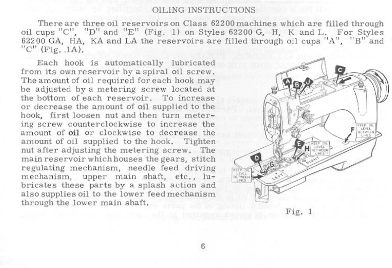
OILING
INSTRUCTIONS
There
oil
cups
"C"
6220 0 GA,
"C"
(
Fig
..
Each
from
he
T
be
the
or
its
own
amo
adju
unt
sted
bottom
decrease
hook, first
ing
am
amount
nut
main
regulati
mechan
brica
screw counte
ount of
of
after
adjusting
reservoir
ng
ism
te
s
these
are
three
,
"D"
1-IA, KA
lA
).
hook
is
reservoir
of
oil
by a mete
of
each
the
loosen
oil
oil
or
su
whi.chhouses
mec
,
ha
upp
parts
oil
reservoirs
and
an
"E"
d LA
automatically
by a spiral
required
ring
rese
amount
nut
rcloc
cloc
pplied
the
nism
er
rvoi
of
and
kwise
kwise
to the
metering
,
needle
main
by
a
on
(Fi.g. 1) on
the
reservo
lubricated
oil
for
eac
h hook
scre
r.
oil
then
w
lo
To
supplied
turn
to
increase
to
decrea
hook.
screw.
the
gears, stitch
feed
shaf
splash
t,
etc., lu-
action and
Class
Styles
irs
are
screw
ma
ca
ted
at
increase
to
the
meter
the
se
the
Tighten
The
driving
62200
machines
62200
filled throu
.
y
-
which
G, U, K
gh
oil
are
and
filled
L.
cups "A"
through
For Styles
,
"B"
and
also
through
supplies
the
oil
to
lower
the
main
lower
shaft.
feed
mechanism
6
Fig
. 1
Page 2
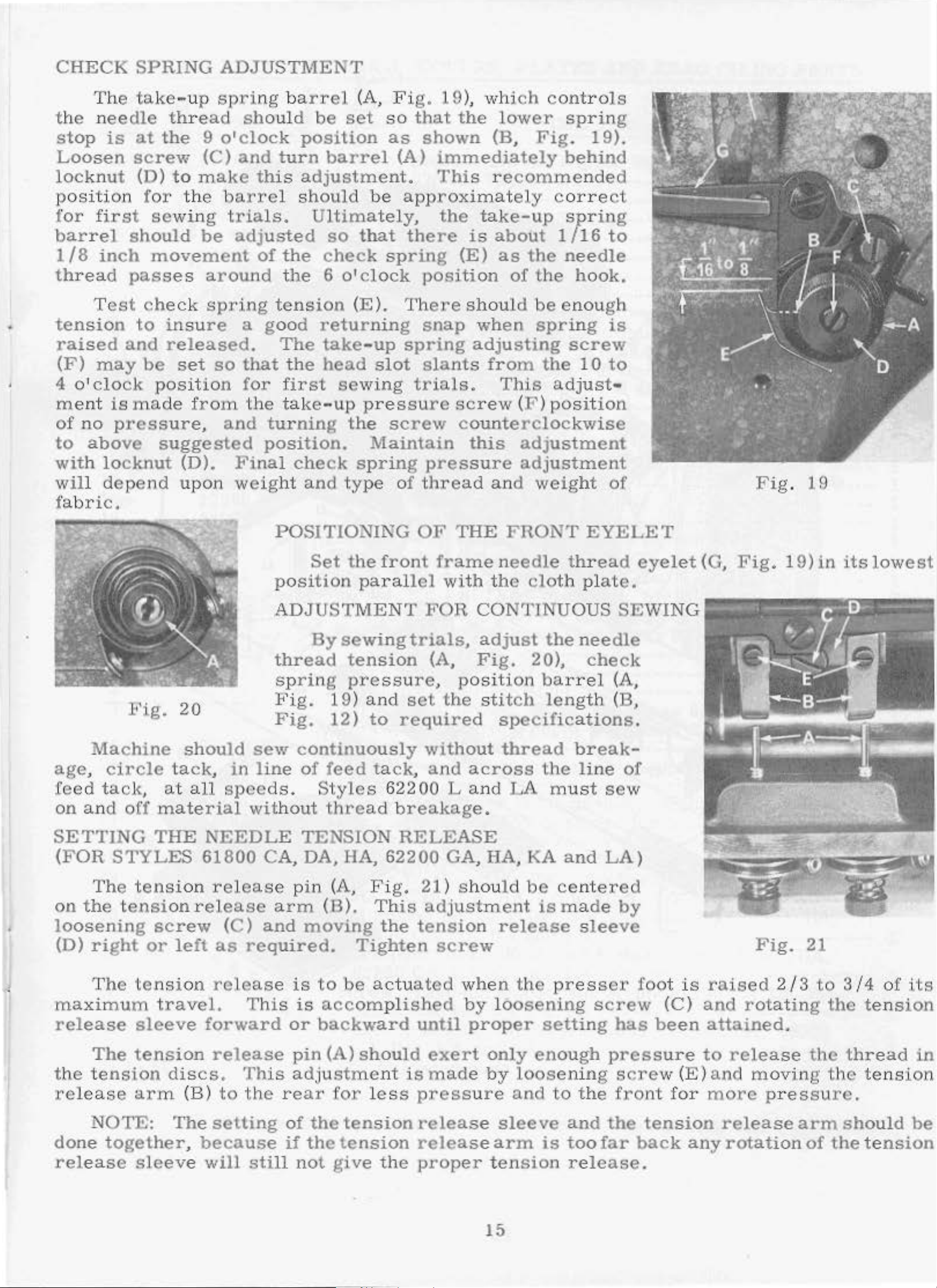
CHECK
SPRING
ADJUSTMENT
The
the
ne
stop
Loosen
locknut
position
for
first
barrel
1/8
inch
thread
Test
•
tension
raised
(F)
4
may
o'clock
ment
of
no
to
above
with
take
edle
is
at
thread
the
screw
(D)
for
se
should
movement
passes
che
to
insure
and
released.
be
position
is
made
pressure,
suggested
locknut
-up
to
wing
9
(C)
make
the
be
spri
o'clock
and
barrel
trials.
adjusted
around the
ck
spring
set
so
from
and
(D).
Final
ng
ba
should
turn
th
is
of
the
tension
a
good
The
that
for
the
the
first
take-up
turning
position.
check
rrel
be
position
(A,
set
Fi
so
as
barrel
adjustment.
sh
ould
be
Ultimately,
so
that
check
6 o'
spring
clock
(E ).
returning
take-up
head
slot
sewing
pressure
the
screw
Maintain
spring
g.
that
shown
(A)
19),
immediately
This
whi
the
lower
(B,
recommended
approximately
the
there
position
There
snap
spring
slants
trials.
take-up
is
about
(E)
as
of
should
when
adjusting
from
This
screw
co
un
terclockwise
this
pressure
ch
controls
spring
Fig.
19).
behind
correct
spring
1/16
the
needle
the
be
enough
hook.
spring
screw
the
10
adjust•
(F )
position
adjustment
adjustment
to
is
to
will
fa
depend
bri
c.
Fig.
Machine
age, circle
feed
on
tacl<,
and
ot'f
upon
20
should
tack,
at
all
speeds
material
weight
POSITIONING
position
ADJUSTMENT
thread
s
Fig.
Fig.
sew
in
line
without
and
Set
type
the
front
parallel
By
sewing
tension
prin
g
19)
12)
press
and
to
continuously
of
.
feed
Styles
tack,
thread
of
thread
OF
THE
frame
wi
FOR
trials,
(A,
ur
e,
position
set
the stitch
required
without
and
62200
Land
breakage.
th t
and
needle
he
weight
FRONT
thread
cloth
of
EYELET
eyelet
plate.
CONTINUOUS SEWING
adjust
Fig.
the
20),
ba
rrel
length
needle
check
(A,
(B,
specifications.
thread
across
LA
break-
the line
must
sew
of
Fig
.
19
(G,
Fig. 19)
~~P.'!!'!.'!!'!
in
its
lowest
'
SETTING
(FOR
STYLES
The tensi
on
the
tension release
loosening
(D)
right
The
or
tension
maximum
release
The
sleeve
tension
the tension
release
arm
NOTE:
done
release
together,
sleeve
THE
NEEDLE
61800
on release
screw
left
as
release
tr
avel.
forward
release
discs.
(B)
The
setting
because
will
CA, DA, HA, 62200 GA, HA, KA
(C)
and
required.
This
This
to
the
still
TENSION
pin
arm
(A, Fig.
(D).
moving
is
t o
is
accom
or
backward
pin
(A)
adjustme
re
ar
f:or
of
the
if
the
not
give
RELEASE
This
the
Tighten
be
actuated
pli
should
nt
les
s
tension
tension
the
21)
should
adjustment
tension
screw
when
shed
until
by loosening
proper
exert
is
made
pressure
release
release
proper
be
is
release
the
setting
only
by
enough
loosening
and
sleeve
arm
is
tension
and
LA)
centered
made
by
sleeve
presser
screw
has
pressure
screw
to
the
and
too
front
the
far
release.
fo
ot
is
(C)
been
(E)
for
tension
back
any
Fig.
raised
and
2/3
rotating
attained.
to
release
and movin
more pres
release
rotation
21
to
the ten
the
g t he
sure.
arm
of
3/4
thread
tension
should
the
tension
of
sion
i.ts
in
be
15
Page 3
16
Page 4
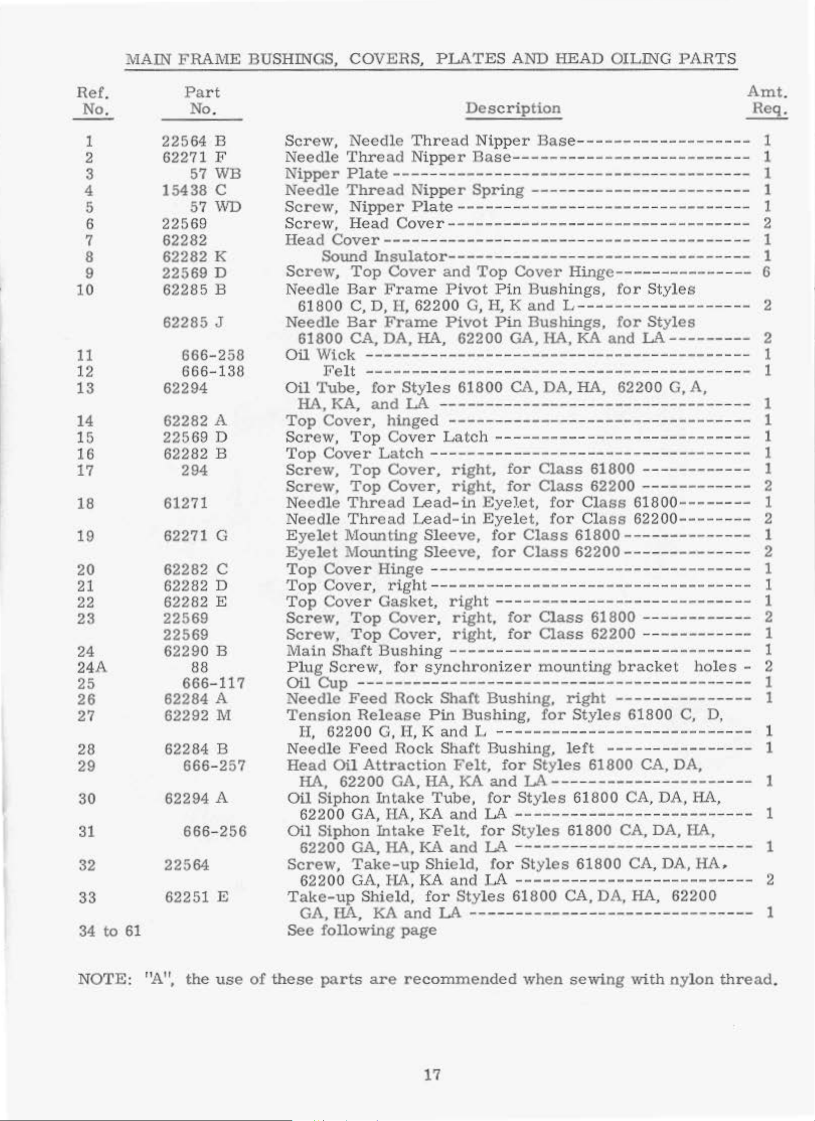
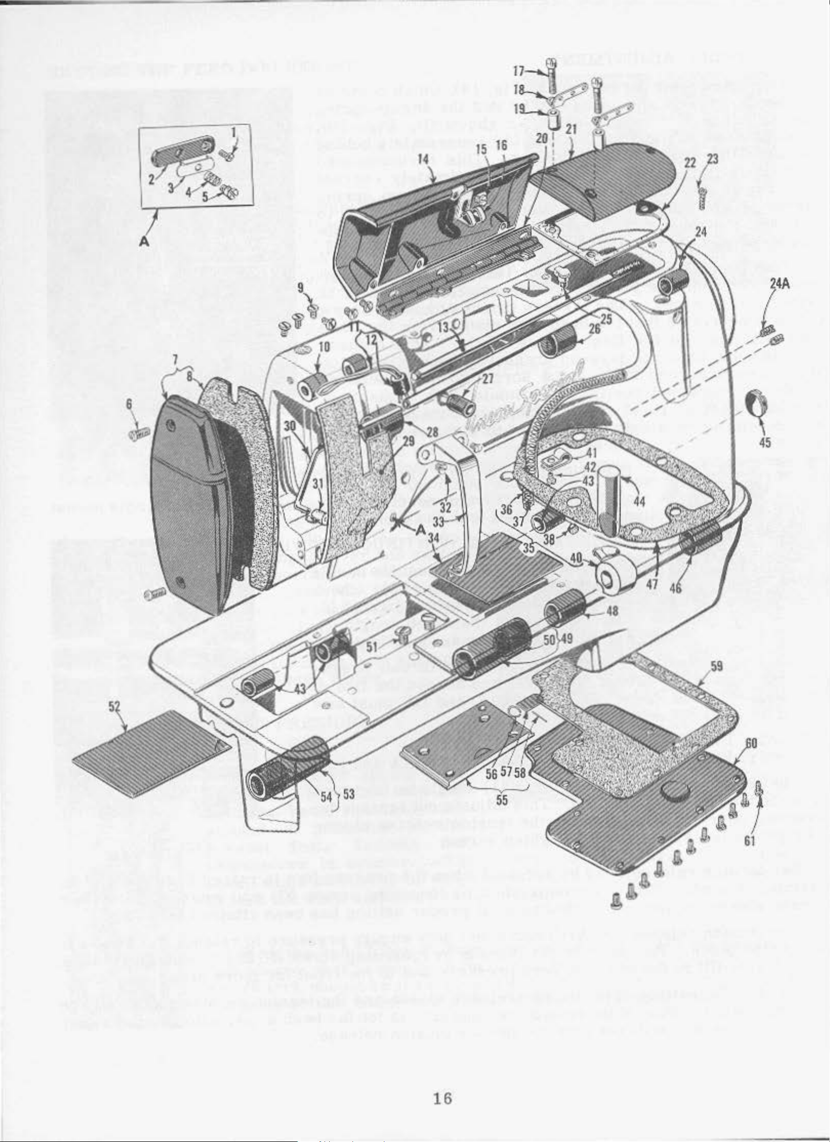
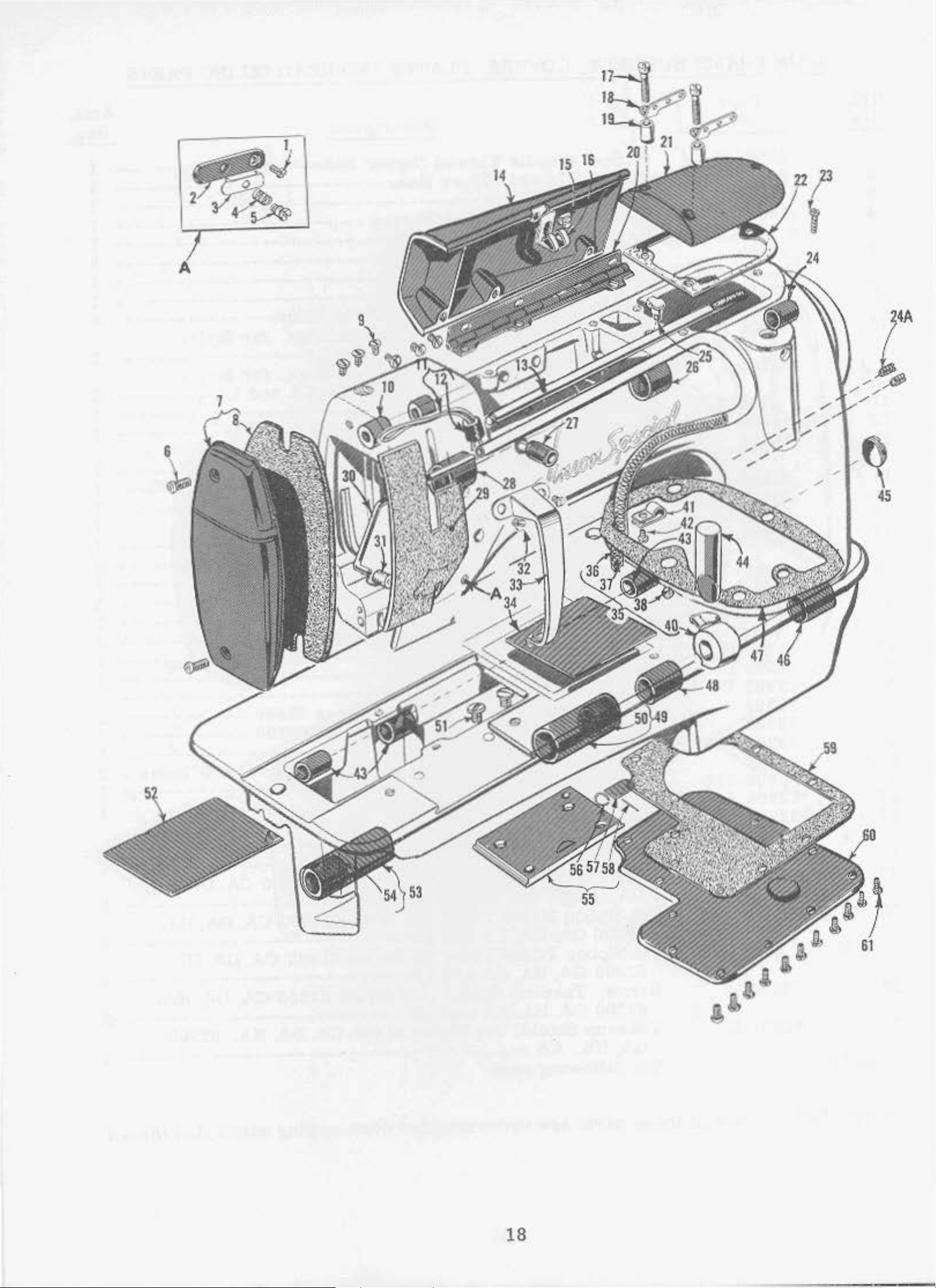
::VIAIN
FRAME
BUSHINGS,
COVERS,
PLATES
AND
HEAD
OILING
PART
S
Ref.
No.
1
2
3
4
5
6
7
8
9
10
11
12
13
14
15
16
17
18
19
Part
No.
22564
62271
15438
57
57
B
F
WB
c
WD
22569
62282
62282
22569
62285
62285
K
D
B
J
666-258
666-138
62294
62282 A
2256
9 D
62282 B
294
61271
62271 G
Screw,
Needle
Needle Thr
Nipper
Needle
Screw,
Scr
ew,
Head
Plate---
Thread
Nipper
Head
Cover----
Sound
Screw,
Needle
61800
Needle
61800
Oil
\'lick ------
Top
Bar
C, D,
Bar
CA, DA,
Felt ----------------------
Oil
Top
Screw,
Top
Screw,
Screw,
Needle
Needle
Eyelet
Eyelet
Tube,
HA
KA
' '
Cover,
Top
Cover
Top
Top
Thread
Th
Mounting
Mounting
Thread
ead Nip
---
per
-----
Nipper
Plate----
Cove
r-
--------------------------------
-
--
---
Insulator------
Cover
Fra
II,
Frame
and
me
Pivot
62200
Pivot
HA,
62200
-----
for
and
Styles
LA
hinged
61800
--
----
--------------
Cover Latch--
Latch
Cover,
Cover,
------------------------------right,
right,
Lead-in
read
Lead-in
Sleeve,
Sleeve,
Description
Nipper
Base---------------
---
Bas
------
e---
--
----------------
---
-----
----
Spring------------------------
----
--
----
Top
Pin
G,
H, K
Pin
---
---
----
Eyel.et,
Eyelet,
for
for
-----
-----
-
------Cover
Bus
and
Bushings,
GA,
HA,
------
CA,
for
for
DA,
---
-
------------------------Class
Class
Class
Class
-
---
------
---
-----
-
-------
Hinge-----------
hin
gs,
for
L---------------
for
KA
--
-
HA,
-----
and
------
-------
----
-
-------
62200
61800
62200
for Class
for
Cl
ass
61800-------62200----
61800----------62200-
-----
--
-
Styles
Styles
L..<\
--
--
-----
-
- -
------------
--------
-----
------
------
-------
---------
------
------
G, A,
---
-------
----------
----
--
--
---
--
---
---
-
---
- -
--
-
---
---
-
----
Amt.
Req.
- 1
-
- 1
- 6
- 2
--
- 1
--
- 1
- 2
--
1
1
1
l.
2
1
2
1
1
1
1
1
2
1
1
2
20
21
22
23
24
24A
25
26
27
28
29
30
31
32
33
34
to
61
62282
c
62282 D
62282 E
22569
22569
62290
B
88
666- 117
62284
62292
A
M
62284 B
666-257
62294
A
666-256
22564
62251 E
Top
Top
Top
Screw,
Screw,
Main
Cover
Cov
er,
Cover
Top
Top
Shaft
Plug Screw,
cn1 Cup
Needle
Tension
II, 622
Needle
Head
HA,
Oil
Oil
Screw,
Take-up
See
Sip
62200
Siphon
62200
62200
G
A
' '
following
---------------------------------------
Feed
Release
00
Feed
Oil
Attraction
62200 GA, HA, KA
hon
GA,
GA,
Take-up
GA, HA, KA
Shield,
IL.<\
KA
Hinge
right
Gasket,
Cover,
Cover,
--
---------------------------------
--
----right
right,
right,
Bushing-----
for
synchronizer
Rock
Shaft
Pin
G,
I-I. K
Rock
and
Shaft
Felt,
Intake
IIA,
Intake
HA,
Tube,
KA
Felt,
KA
and
and
Shield,
and
for
and
Styles
LA
page
----
---
-----
---
---------------------------for
for
----
Bushing,
Bushing,
L
--
Bushing,
for
and
for
LA
for
LA
for
LA ------
-------------------------------
Class
Class
----mounting
for
61800 62200
---
right
Styles
----bra
--------------61800
---------------------left
Styles
LA-
Styles
----------------------
Styles
--
Styles
61800
----------
61800 CA, DA, IIA,
---
----
CA,
61800
61800
----
---
61800
CA, DA, HA,
-----
CA, DA,
----
DA,
HA,
------
--
------
--
------
-
----------
cket
C,
-----
-- --
CA, DA,
-
--
-----
---
-----
--------
62200
--
----
----
holes
--
D,
--
---
---
-- --
HA,
- -
--
-
- 1
- 2
- 2
--
--
- 1
--
- 1
--
1
1
1
1
1
1
1
1
1
2
1
NOTE:
"A",
the
use
of
these
parts
are
recommended
17
when
sewing
with
nylon
thread.
Page 5
\
~~
L4A
/
/
/
/
/
'
~
45
18
Page 6
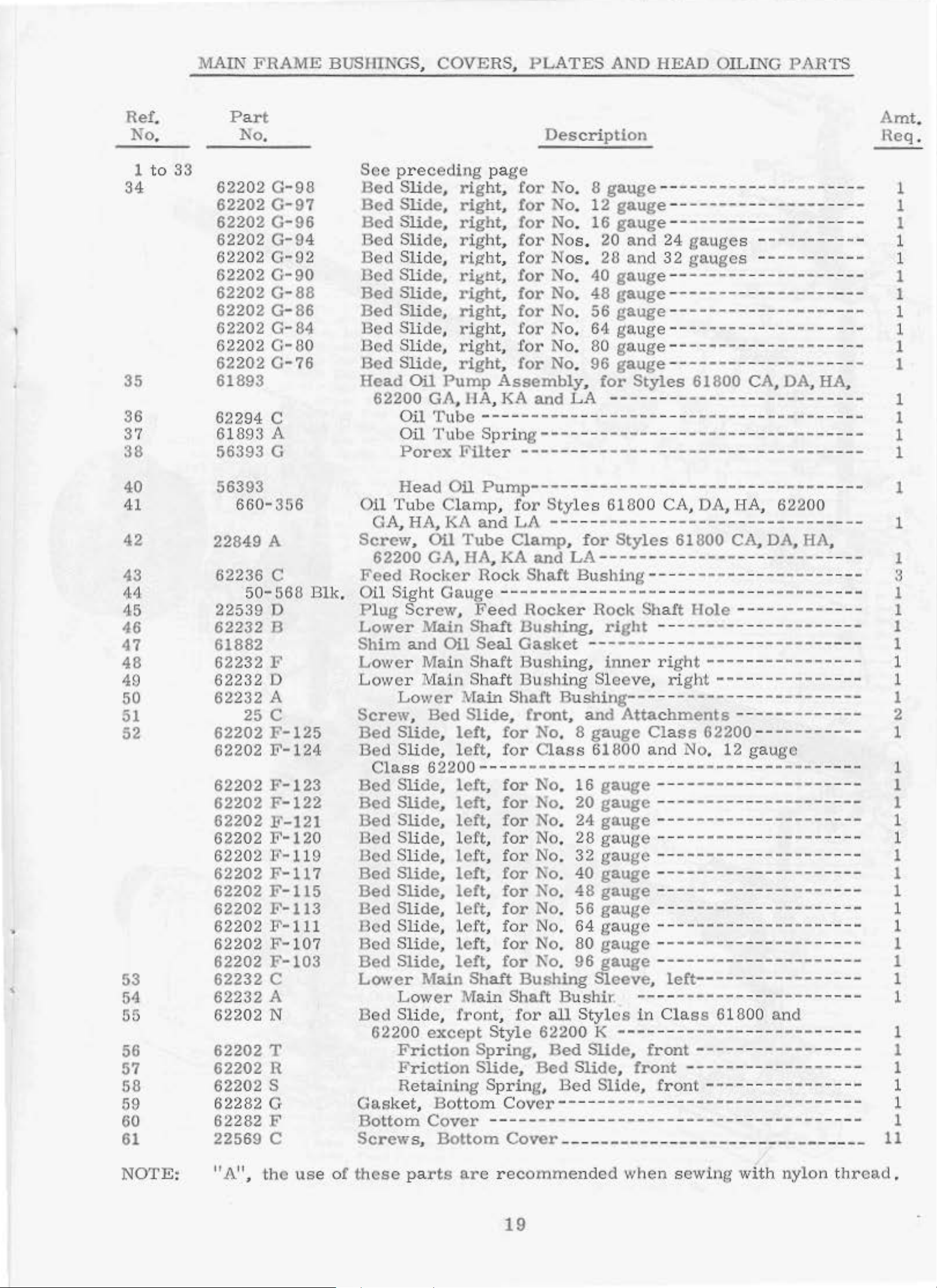
l\MIN
FRAME
BUSHINGS,
COVERS,
PLATES
AND
HEAD
OILING
PARTS
Ref.
No.
1
to
33
34
I
35
36
37
38
Part
No.
62202
62202
62202
62202
62
202
62202
62202
62202
62202
62202
62202
61893
62294
61
893
56393
G-98
C-97
C-96
G-94
C-92
G-90
C-88
G-86
G-
84
C-80
C-76
c
A
G
Sec
Be
Bed
Bed
Bed
Bed
Bed Sli
Bed
Bed
Bed
Bed Sli
Bed
Head
pr
d Slide,
Slide,
Slide,
Slide,
Sli
Slide,
Slide,
Slide,
Slide,
Oil
62200
Oil
Oil
Porex
eceding
de, ri,ght, f
de,
de,
Pump
GA,IIA, KA
Tube--
Tube
pa
right,
right,
right,
rig
ht,
rignt,
right,
right,
rig
ht,
right,
right,
Assembly,
Sp
Filter
Description
ge
for
No. 8
for
No. 12
for
No.
for
No
or
No
for
No. 40
for
No.
for
No.
for
No.
for
No. 80
for
No
and
--
------
ring----
----
s . 20
s.
. 96
LA
-
-
--
- -
gauge------------------
gauge---------
16
gauge--------
and
28
and
gauge--------
48
gauge-------
56
gauge----------------
64
gauge--------gauge-------gauge
for
----
--
-----
--
----
-----
24
gauge
32
gauges ---------
--
-----
Styles
---
- -
-
61800
------------------
- - -
-----
--
-----
-------------------
s -
--
---
--------
--------
---
-
------
--
-----
-----
- -
-----
-----------
-
------
- - -
-----
-----
CA, DA, HA,
---
--
- - - 1
-
----
- - 1
--
- - - 1
- - - - 1
- - - - 1
- - - - 1
----
---
--
--
---
- - 1
Amt.
Req
1
- 1
1
1
- 1
- 1
1
1
.
•
40
41
42
43
44
45
46
47
48
49
50
51
52
53
54
55
56
57
58
59
60
61
56393
660-356
22849 A
62236
22539 D
62232
61882
62232
62232
62232
62202
62202
62202
62202 F-122
62202
62202
62202
62202
62202
62202
62202
62202
62202
62232
62232
62202 N
62202
62202
62202
62
282 G
62282
22569
c
50-568
8
F
D
A
25
c
F-125
F-124
F-123
F-121
F-120
1''- 119
F-117
F-115
F-113
F-111
F-10
F-103
c
A
T
R
s
F
c
Blk
7
Head
Oil
Tub e
GA, HA, KA
Screw,
62200
Feed
Oil
.
Plug
Lower
Shim
Lower
Lower Main Shaft Bushing Sleeve, right---
Screw, Bed
Bed
Bed Sli
Cla
Bed
Bed
Bed
Bed
Bed Sli
Bed
Bed
Bed Sli
Bed
Bed
Ded
Lower
Ded
62200
Gask
Bo
Screws,
Rocker
Sig
Screw,
and
Lower
Slide,
ss
Slide,
Slide,
Slide, left, for
Slide,
Slide,
Slide,
Slide,
Slide,
Slide,
Lower
Slide, front, for
Friction
Fr
Retaining Spr
et,
ttom
Oil
Pump---------------
Clamp, for
and
Oil
Tube
GA,
ht
!\<lain
Main Sha ft
de,
62200 -
de,
de,
Main
except Style
iction
Cover
HA,
Gauge--------
Oil
Main
Slide,
left, for
left, for
left,
left,
left, for
left, for
left,
left,
left, for
left
left, for
left,
Main
Bottom
Dottom
KA
Rock
Feed
Shaft
Seal
------for
for
for
for
, for No. 64
for
Shaft
Spring,
Slide,
Cover
--------------------------
Cover
Styl
es
618
LA
Clamp,
Shaft
Shaft
ing, Bed Slide,
- -
---
-----
for
Styles
and
Shaft
Rocker
Bushing, right
Gasket ------
Bushing,
front,
1\o.
Bushing
LA--------
Bushing-
- Rock
Bushing--
and
No. 8
Class
No.
No. 24
No.
No.
N'o. 40
No. 48
No. 56
No.
N'o.
all Styles
62200
Bed
Bed
gauge
61800 and No. 12 ga
----16
20
28
32
80
96
Sleeve,
Bushir
K
Slide,
Slide,
- -
---
--
- -
------
inner
Atta
-------------
gauge--gauge
gauge--------------------gauge
gauge--gauge ---------------------
gauge------------------
gauge
gauge--gauge
gauge
.
--------
---
----
-
00
CA, DA, HA, 62200
- - -
-------------------
61800
-
- -
--
--------
Sha
ft
---
--
- -
right----------------
--------chments-
Class
--
------
-----------
----
-------
--------------------left-----
---------in
Cla
front----
front
front--
--
- - -
----
-------------------
------
-----
----
Hole----------
------
-----
62200-----------
-----
----
----
----
ss
----
------------------
------
- ------
CA,
-- --
- -
----
61800
-- ----------
DA, HA,
----
- ----------
--------
- -
- - -
- - - -
-
---
- -------
- - -
-----
---
-----
--
------
--
---
---
----
------
-
----------uge
----
-- --
---
- -
---
-
---
------
--
-----
----
----
------
------
-----and
---
------
---------
-------
-----
- -
-----
---
---
----
----
-- --
----
-----
----
-
-----
- - - 1
--
- - - 1
-----
- -
----
---
-----
- -
--
1
1
--
- - 3
- 1
--
- 1
- 1
--
- 1
--
- 1
--
- - 1
--
1
1
1
1
1
1
2
1
1
1
1
1
1
1
1
1
1
1
1
1
1
1
11
NOTE:
"A", the
use
of
these
pa
rts
arc recommended
19
when sewing
with nylo
n t
hread.
Page 7
,
.......
I
I
I
I
I
I
I
I
I
I
I
/
20
Page 8
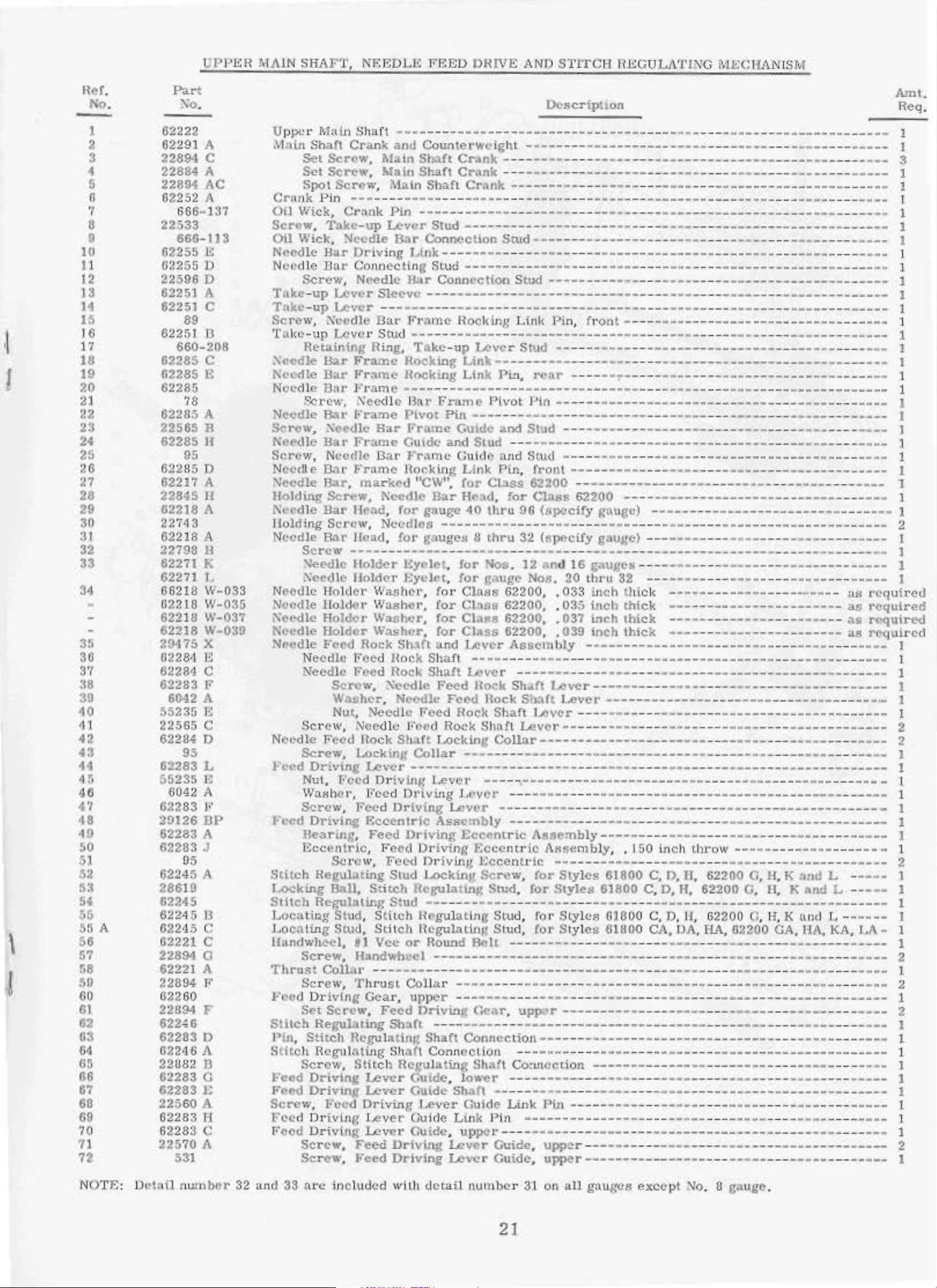
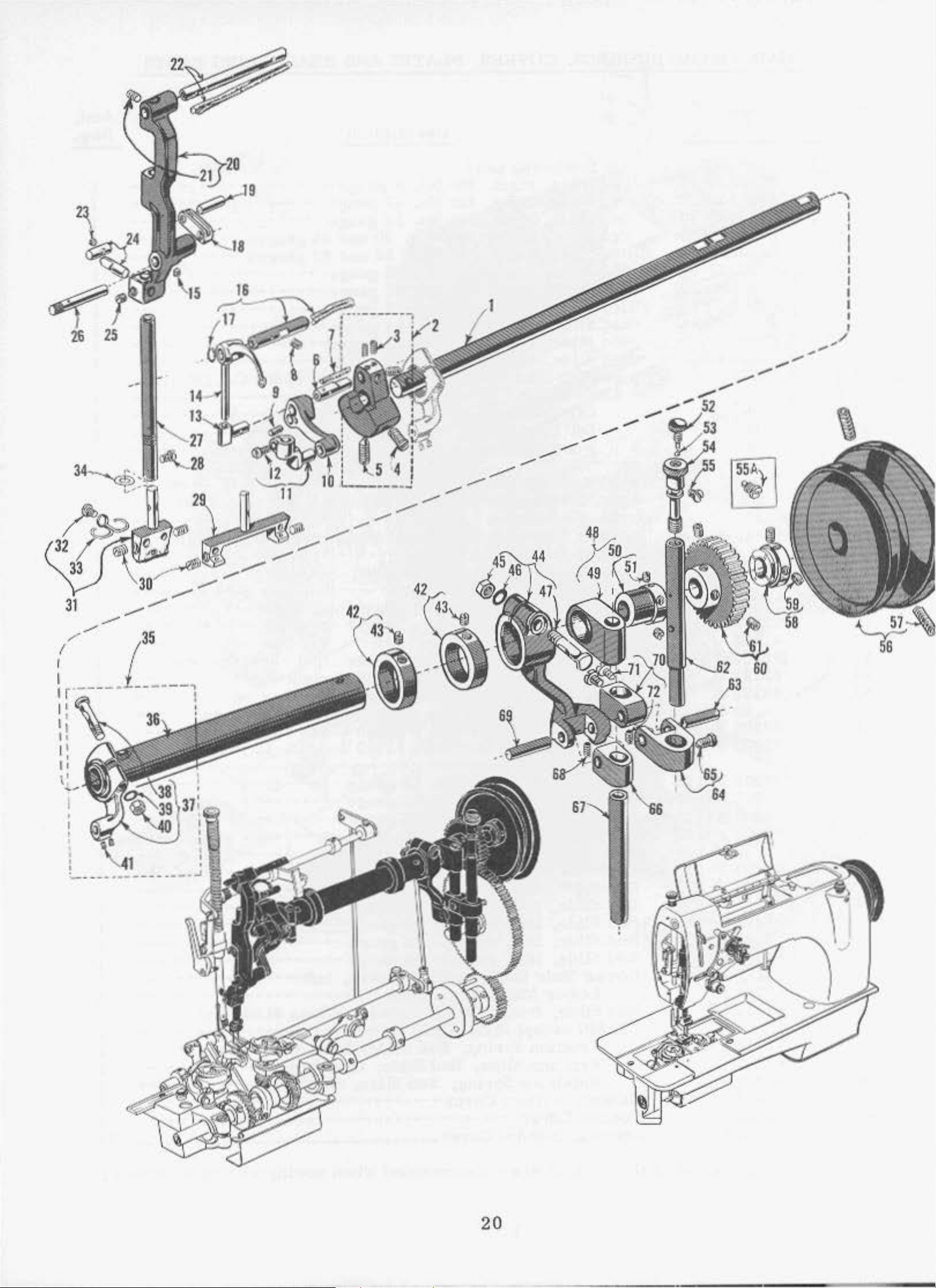
UI'PER
MAIN SHAF
T,
NEEDLE
FBEI.l OIHVE
,\Nl)
Sl'J'l'Cti
REGULJ\'1'1:'-'G MECHANISM
II
1
\
I
llcf.
No
-
I
2
3
1
5
(i
7
8
9
10
1l
12
13
H
I~
I 6
17
18
19
20
21
22
23
24
25
~6
27
28
29
30
:u
32
33
34
35
36
37
38
30
10
"1
42
4:J
H
45
46
47
•18
49
50
31
52
53
54
S5
5!l
56
57
58
50
60
6 1
62
63
64
05
66
67
68
69
70
71
72
A
Part
.
~0
.
62222
62291 .4
22694
22684
22891
62252 A
22533
62255
0,.255
22596
c
A
AC
666
- 137
666-113
E
D
D
62251 A
62251 c
89
62251 B
660-208
62265
62285
c
E
62285
78
62285 A
22565
62285
R
H
95
62285
62217
22645
62218
22743
62218
22798
D
A
H
A
A
ll
62271 K
6227
1 I,
66218
W-033
02218 W
622
18
W-037
62218
29175
02281 E
62281 c
62283
6042
!)5235 E
22565
62284
W-039
X
I'
A
c
D
95
62283 L
5523
5 E
6042 A
G22
83
I'
29126
62283
62283
BP
A
J
95
62245
A
28619
62245
62245 B
62245
c
62221 c
22894
62221 A
22894
G2260
2289
62~6
62283
G
F
4 F
I)
G2246 A
22
082 D
62283 G
62283
22560
62283
62283
225
70
531
t:
A
li
<.:
A
-035
Upper P.
i\+tnln Shaft
Crnnk
Oil
Screw. Take-up
Oil
Nct"dle
N<:l
Toke-up
Take
Scre
Ta.lte-
~ccdle
Needle
N(;cd
Needle
Screw
NC'Nile
Screw,
Need
'lccdle
Holding
1\cedle
IJolrting
Needle Bar
N
ced
Needle
i\oedlc
t\cedle
NC'ed
Needle
:
Feed
Jo'ccd
Stitch Hogulating
l.o<:king
Slllch
Locath~g
Locoting Stud, Stitch
Uundwhe<!l,
Thrust
fnin Sh11ft ----
Crank
Set
Scr~w.
Set
Screw.
Spot
Scre
:Pin .... - -
v.:tck.,
Wic:::k.
:d le Dar· Co•mecttng
Screw,
-up
w, t'\ct:dle
Rctainin~
Je
Screw,
Crnnk
Needle
Har
Dri
Needle
Lever
Lever .............................. ........................................ ...... ........................................ .................. 1
up
I...cvc
Bar
Fra.t:nc Uocking Link..................... ........................................................................................ 1
Bar
Frarnc
Bur
J<'rarne ------ -- ......
Nee
Bar
Frame
, Xee<llc
Har
Frame
Ne
edle
le Do
Screw
~eedlc
Xeedlo- H
l~
t•
Frruue
Bar,
Scr<"w,
Bar
Head, for
Sct'
Ct\'.
Head,
--·-
Holder
HoldO
Holder
Holder·
Holder
lc
'Feed
Nec:d
lc
Peed
Needle
F'Ped
Screw,
W:~.shcr
Nut.
Screw,
Screw,
Dri.vln&
Nut,
\Vaaho1·,
Screw,
DrLvinc
Bearing, Feed
~'eedlc
Feed
l..ocki.ng
Feed Driving
Feed Orivl.ng
Eccentric,
Sc
rew,
ll8ll, Sriteh
Rcgulnling
Stuc1, St
ltl
Screw.
l..fandwhccl ...............................................
Collar
and
~>fain
Main
w,
Main
---
Pin
Lever
Bar
ving
Sleeve
Bar
t• Stud ------
Ring,
Hocking
dle
Bar
Cutdc
Oat· Jo""rarnc ()uid
rharked ''C\V".
~cedle
Nc..:-
for gnu
---
------
t:yclet. for
older
l'
Rock
l!ock
Le\<·Cr ................................................................................................... .............................. 1
F~cd
Eccentric
EyclP.t
Washer. fo
Waah
Washer,
Washer
Sh.lft
Hock
Rock
~ecdlc
,
Needle
Needle
Shn
l)r•i
F
eed
Feed
Slud
Stud ---
itch
Vee:
- .......................................
Screw, Thrus<
l•'<~<:d
Stllch
Pin. Stitch
Stitch
Feed
Jo~ct"'<J
Screw,
F~<:d
r-
Dr
iving
Set
Screw,
Regula
flcgul
Screw,
Drlvln.& Le-,·cr
Driving
Feed
Or
ivlng
eed
Ori
ving
Screw,
Sere"'',
crcar·,
Feed
ling
Rcgu
t\tU
Stitch
Shaft
Jatin,g
tg
Sh
Lever
Driving
J
.ever Guide
Lever
Feed
Feed
Driving
Driving
RcguJatin~
Dc!icription
- -
----
.... --- .................... ---.............. ........ ---------
Counterweight
Shaft
Shaft
-----
Crank-----
Crank
Shafl
-------
Ct':tnk ....
......................................................... .............................. .......... 1
----
- -
---
------
............................................. ........................................................... 1
....
........................................ ..................................................... 1
----
----------
- ...................................... ---
------------·---
.....................................................................................................................
Slud
Conoeotlon
J,~(
r
)k
Har
................................................................................................. .............................. 1
F"r~me
Toke-up
Bnr
Plvot
Frome
Hocking
,:raugc
dlfls
<.:t',
,
Shaft
Shaft
Fee
F
ncd
rt
Collar
ving
Driving
Dr•iving
r>r·iving
Loc
RcgulatinR
HPgulatlng
11cgulolin
or
Round
---------------
----
St-ud
.................................................................................................................. 1
Conn
Hoe
- .............................................................. --------
Llnk
Frame Pivot
Pin
Guide
and
Link
for
Bar
He:ad.
40
........................
ge.s u
--
------
,
tor
1·
Clo
for
C1:1ss
for
ClaM6
tor
Class
and
Lever
Feed
Feed
d
Rock
Rock Shaft Lever
Loc
king
................................................................................................................... 1
Lever
J.
Lever -----------------
Assembly ----
Eccentric
king
----
Stud
............................................. .. ................................................ 1
---
----------
ection Stud
lting
Linl
<
Lever
..........
Stud ---
g:.1uge
tts
--------------------
J~vcr
Stud
Pin, rt'ar -----
...
...................... .... .........................
:Pin ............................................................ ................................ 1
....
.........................................................
and
Stud
o [
Class
thru
thru
Nos. 12
-----
wd
St
ud -----
Plst, fronl ---
62200
for
Cln.Hs
96
(8pccify
......
............
32
(~pectfy
----
-----------
.1nd
No~J.
62200,
62200, . 035
62200, . 037
62200, . 039
As
sem
---
----------
Uock Sl1art
Rock
-
cvor
Ecc
Bccentl·i<:
Screw.
-------------------
l~
Acll
Sb
..
·•rt
Shaft lAver
Collar--------------
---------
-----------------
-----
Assembly
:entrio
!or
Swd, !or
Stu
d,
J'o1·
Stu
d,
ror
------·--
..............
Colla
r -
upper ---
Driving
---- ~---
Shaft
<'l't
Conn(~c
Ouidc
Guide
~
Sha(t ------
I
~ever
Ltnk
Ouide,
Lever
Lever
--------
----
(;ear. uppQr
Connection----
~ion
Shaft
Jowcr
t:uide Link
upper---------
-----
-----------------
--
--
-----
............ .......................... .............................. ................................ 1
CO.:Ul
CCt
--------
-
Pill
Guide,
Guide, upper
PU
.................................................... ............ .......... ....
upp!.'r ----------
----
----
----
---
----
-----
---
------
-----
--
-----
Pin
, f\•ont
.......................................................................................... 1
.............................. _ ........................................................... 1
----
---
----
--
................................................................................... 1
62200 ....................... ...................................... .......... l
gnugc) ..
.............. -----...............................
- - .................
- --
-----
..
........................................ .... .................. ...... 1
-':"·--------
.....
---
----·----
---
.......... ..................................................... 1
------------
................................................ .............. 1
......
---
-----
----
....................................... ...... 1
.... .... ..
---
--------
gnu}:'c) ------------
----
16
20
. 033 i
gauges
lhr
u
32
.n<:h thick
inch chi
lnch
inch
----------------
- -
---
---
ck
thick
thick
---------------
----
-----
....................................
................................................
-----
............................. ....................
----
bly .................................................................................. 1
--
- - ..........................................................
-----------
l.e"-er---·
Lever
--
...................... ................................................................. 2
---~
..
-- ------------
............................ ...... .......... ............................... 1
----------
---
............................... ...... .......... .... .......................... - 1
---
-----
---
.................................. ............ 1
----
...................................... ...... 1
-----------
- -............................................................... 1
--------
---
---------
............................................................................ 1
AMsembzy,
.............. ...................
Slylcs
Styles
S
tyles
Styles
-------
.150
61800
61800
61800
61800 CA,
----
C,
C,
-----
C,
--------
--------
......................................................... ----
------------
---
---
.............................................. ................ ......................... 2
---
---------
- - ................................................................................... 1
ion
............................................................................... 1
-----
----------- - --
t -
- - -
----
----
-----------
--------
.......................................... -
--
---
--·--------·--~-
...........................................................
----------
----
---
-----
lnc h
thl'0\1.•
.....
.......................... ........................... 2
0,
II,
62200
0, H.
D, 11, 62200 G,
62200
---
------------------
OA, HA, 02200 G.4, HI\,
-----
---
------
----
-----
-----
-----
------
--
-----
--------
------------
-----
--
-............................................. 1
-----
---
- .............. ......
---
-----
----
- ------
-----------
....
---
--------
............... ..................
---
............................. 1
...................................... 1
........
........................... ........... 1
.......
.................................. 1
---------
----
-------
-------
------ -
----
.........
----
------------
.......................... 1
-----
---
------
---
------
.................... 2
----
-----
---
-----
- -
as
as
----
-----
---
------------
--
---
................
G,
H, K nnd
G,
11, K ond L --
H, K nnd
----
------·----------
----------
--------
- --------
----
-----
---
---
------
---
--
as
as
--·--
------
---------
- ........................... 1
...
-----
-·--
............................... 1
---
------
---
--
...................
L
--
---
T
.,. .............. I
KA,
..................... 2
----
---
--------
-------
----
---·-
----
-----
.....
.............. 1
--
------
-----------
........ 1
----
----
I.
Ami,
Req,
..
.... 1
3
...... 1
t
1
1
1
1
---
1
1
.c·cquire.J
required
required
rt'quired
.....
1
1
2
---
....
---
---
A-
--
1
1
1
I
I
I
1
---
1
2
1
1
1
.......
1
2
1
N()TE:
JJ
ut>lil ttufn
bor
32
and
33
are
in
clu
ded
with
<.1..:-tail
nu•nb<~
21
r
31
on
an
gnu~o,
1C8
except
~o
.
a ga.uge.
Page 9
22
Page 10
Ref
o.
N
.
Pa
No.
rt
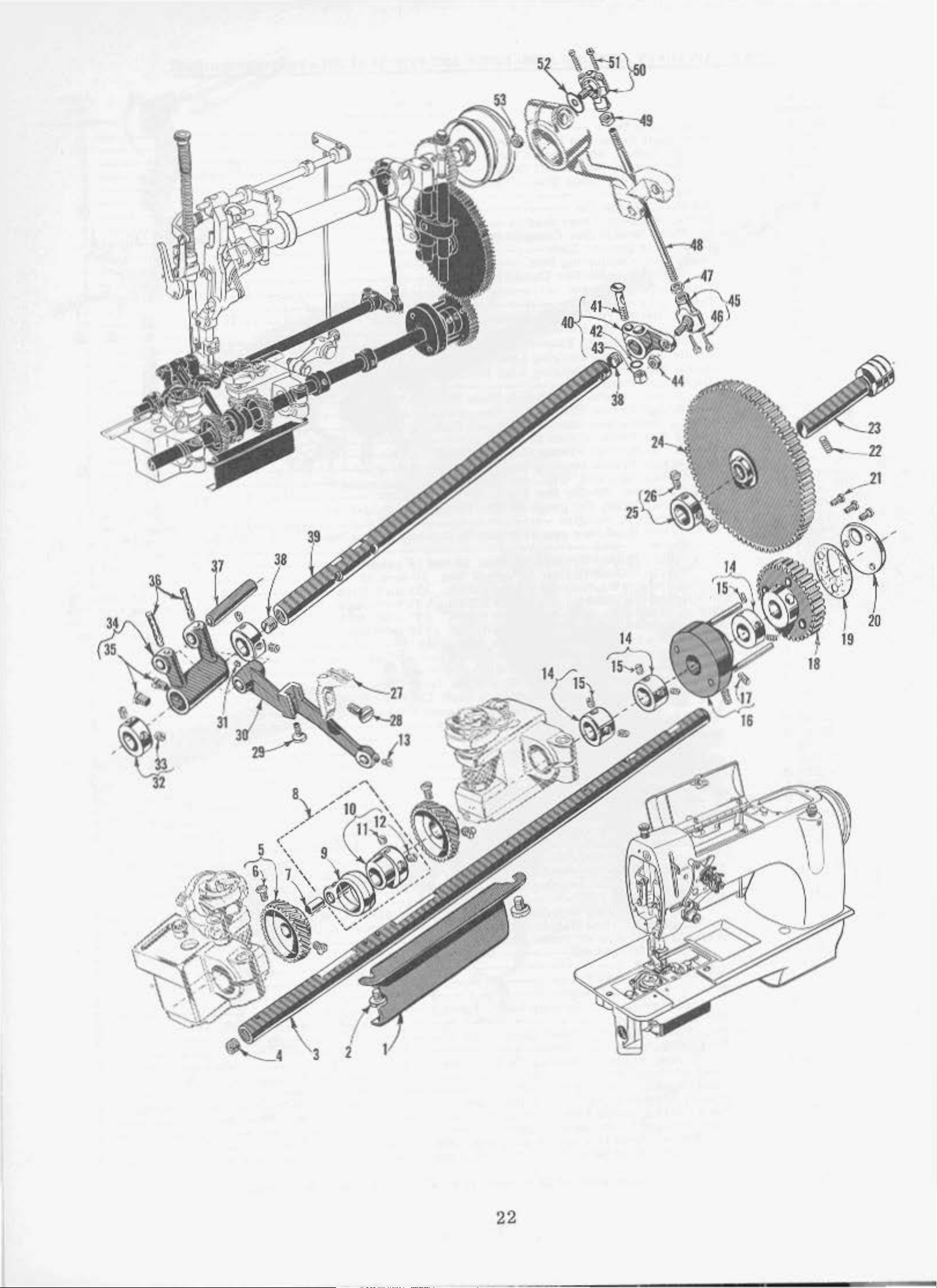
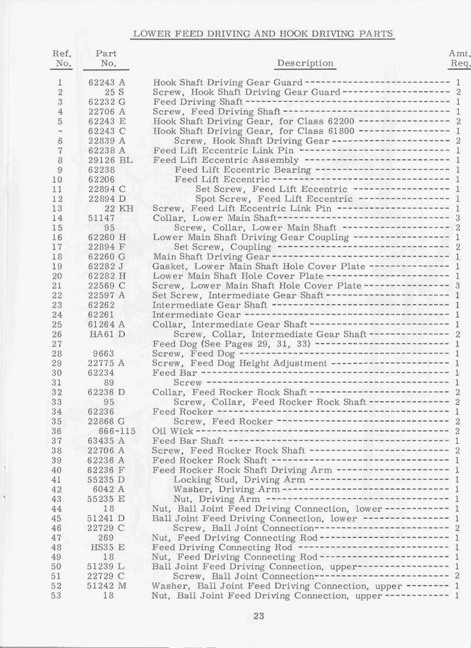
LOWER
F E
ED
DRIVING AND HOOK
Description
DRIVlNG
PARTS
A
mt.
Req.
1
2
3
4
5
6
7
8
9
10
11
12
13
14
15
16
17
18
19
20
21
22
23
24
25
26
27
28
29
:30
31
32
33
34
35
36
37
38
39
40
41
42
43
44
45
46
47
48
49
50
51
52
53
62243
25
62232
22706
62243
6
2243
22839
62238
29126
62
238
62206
22894
22
894
22
51147
95
62260
228
94 F
62260
62282
62
282
22569
225
97 A
62262
62261
264A
61
HA61 D
9663
775
22
62
234
89
62236
95
62236
228
66 G
666-115
63435
22
706 A
62236
A
62236
55235
6042
55235
18
5124
1 D
22729
269
HS35 E
18
51239
2272
9 c
51242
18
A
s
G
A
E
c
A
A
BL
c
D
KH
H
G
J
H
c
A
D
A
F
D
A
E
c
L
M
Hook Shaft Driving
Screw,
Hook
Sh
Gear
aft D
rivi
Feed Driving Shaft---------
Screw
ook Sha
H
H
ook
Fee
Feed
Screw,
Colla
Low e r
Main
Gas
Lower
Screw,
Set
nterme
I
I
nte
Collar,
Feed
Scr
Screw,
Feed Bar
Collar,
Feed
Oil
Feed
Sc
rew,
Feed
Feed
Nut,
Ba
ll
Nut, Feed
Fee
ut,
N
Ball Joi
Washer,
Nut,
,
Feed
Shaft
Screw,
d
Lift
Lift
Feed
ft
Driving
Driving
Driving
Hook
Eccentric
Ecc
Lift
en
Ec
tric
Feed Lift Eccent
S
et
Screw,
Spot
F
eed
r ,
Lo
Screw,
Main
Set
Screw,
Shaft
Screw,
Lift
wer
Co
Sh
Ma
lla
aft
Co
Driving
ket, Lower Ma
Ma
in Shaft
Lower
Screw,
diate
rmediate
In
ter
Screw
Dog
ew
, F
' .
(See
eed
Feed
Ma
In
termediate
Gear
Gear
me
diate
Co
llar
Pages
Dog
Dog
--------------
Sc
rew
Screw,
Rocker
Screw,
Wick----
Bar
Ro
Roc
Locki
Washer,
Nut,
Ball Joint
Joint Fee
Screw,
- - - -
Fee
d R
Collar,
Fe
Sh
aft
Feed
cker
ker
ng Stud,
Dr i
Ball
--
ocker
-------------------ed
-
--------
----------
Rocker
Rock
Rock
Driving
ving Arm
Feed
d Driving
Joint Conne
Driving
d
Drivi
Feed
Screw,
Ball
ng
Driving
nt
Feed
Ball
,Joint
Co
nnecti ng
Driving
Ball
Joi
J oi
nt
Feed Drivi
Sh
aft
Gear
Gear, for
Shaft
Driving
Link
Assembly
centric
ric ---------------------------------
Feed Lift Eccentr
Feed Lift
Ecce
in
r ,
Dr i
nt
Shaft--
Lower
ving Gear
upling
Gear---------------------------------
in
Shaft
Hole Cover
in Sh
aft
Shaft
----------Gear
I
ntermediate
29,
------Heig
- - -
ht
------- ---Rock Shaft-----
Feed
Rocker--
-
Rock
Shaft---------------------------------
Sh
aft
Driving
Arm-
------------------------
Driving
Connecting
Co
nnecting
nt
Connection-
Feed
Gu
ard---
ng
Gear
-
----------
---------
, for
Class
Class
Pin ------
- -
---------------------
Guard--------------------
-
--
- -
- - -
Gear
---
----
62200
61800
--
---
-
---------------------
--
----
-
--
------
--
---------------
-------
------------
Bearing --------------
ic
------------------
Ecce
ric Link Pin
ntric
-----
-------
----------------
---------------------------
Main
-----------Hole
Shaft
--------
Coupling
-----
Cov
er Pla
- -
--------
----
te
----------
Plate-----------------------
Hole
Gear
-------Shaft-
31
-
-----------
Adjustme
-
-----------
Rocker
Cover
Shaft
-
,
33)
-----
Plate----------------
------
------
-----------
-
-----------
--------
-
--
-----------------Gear
-------------------------
nt
- -
------
Rock
- - -
- -
------
Sh
aft-
--
------------------
--
---- ---- ----
--
------
---------
-------------
------
----------
Shaft------------
-----
---
-----
--------------------------------
-
------------
Shaft
Driving
Arm----
-
-----------------------------
-----------Arm
- -
----
----
--
------
-
-
----------------
-
--
Connection, lower
Connection, lower
ction
-----
-
----------------
----- ---- --
Rod------------------------
Rod --------------------
Ro
d------------
Connection
Driving
ng
Con
,
upper------
----
------------
Connection,
nect
ion
, upper
upper
-----
--
- - - - - - - - 1
- -
--
--
-
----------
---------
--
-
----------
-
---------
--
------
-
-------
--
--------
-----------
- -
---
---
-
-----
-
---
-
-------
- - - -
---
------------
-
-----
------------
-----
-- -
-
- -
-
------
-------
- -
- -
------
- -
-- -------
--
--
--
-- ----
- -
--------
--
- -
--
---
----
- 2
----
-
--
- - - - 2
- 2
-
--
--
-
----
---
-
-
-
----
--
- -
-
--
-
-
--
-
----
-
---
----
- 1
-
- - - -
-
---
-
- - -
--
---
- 2
---
--
-- --
- - - 1
- 1
2
1
2
1
1
1
1
1
1
1
1
3
1
1
1
1
3
1
1
1
1
2
1
1
1
1
1
2
2
2
2
1
2
1
1
1
1
1
1
1
1
1
1
1
2
1
23
Page 11

24
Page 12

A
FOR
61800 CA,
STYLES
DA,
HA
Fig.
lA
7
62200
FOR
GA, UA, KA,
STYLES
LA
Page 13

PRESSBH BAR,
1"00'1'
LD"
l'
AND T ENSIO
:> RELEAS
J;; PAR
TS
I
2
3
~
~
6
7
a
0
10
I I
12
I
:1
14
15
16
17
18
19
20
21
22
23
2•
25
26
27
28
28
29
30
~0
31
92
33
34
3~
35
36
37
38
39
40
41
<12
13
44
15
46
17
48
lo9
50
51
J2
53
~
55
56
57
58
59
60
61
62
63
61,
(1
5
A
A
A
ParL
~o
.
81257
81256
G
G
62256
62268
6229
22894
6
612
124
2 K
8 H
4"
A
IV
I I
88
62
268
62292
22
62292 w
62268
22.8
62268
62268
62268G
11635
22817 c
22712
I'
ea
o
585
c
H
4
660.142
J
660-142
F
B
.A
9937
2287
4
61292 c
61
392
F - fl
61292 H
61492
62292 s
62292
51292
512!.12
62292
11
109
u
A
0
294
J
62292 c
62292
62292
51235
62292
62292 N
T
p
G
L
22760
62292
22
29475 AL
R
569 c
22562
622
53
ll
62253 B
62253 \(
62253 L
62253 D
622.)3
62253
62271
J
F
c
62259
77Q
93 A
61265
22799 \1
22758
B
62268 E
62256
G22
57 A
22726 L
22569 F
Description
Presser
\'lasher,
Pr
essez·Spring
Presser
Tonsi
Sti
tch
L -
S
t.itch Regu
I<
A,
P1·esset' lfo
Tension H.cl
and LA
Scr
ew, T
TensiOJl
~nd
Presser
Cotter
Presser
Cotter
Presser
Pt-e:sser
Nut, Presser
Screw, Pressor
Screw
Lo
ck Nu
Adjusting
T
ension
Nee
dle
Tensi
Tension
and
·re
nsion Oisc---
To
nsion
Teo
aion
Tenaio
T
ens
Se
t·cw,
and L -----
Tension
Tcns.ion
Tension
LA
Spacing
Spacer
and L --
Tension
Te
nsion
Scr~w
1 . .............................................................................................................................. ..
Tension D
[,
-------·------·-----------------
Scre w,
Check
::"lecdle
Presser
Screv;, l.fand
Screw. Presser
Presser
PresserBarConncet.lon
ScJ•e,
Presse
Scre\v, ·rhroa
T
hro
Sprlna
Preseer
Foe¢
on
Release
Screw
S
,
Regulator
-------
LA
la
---
crew, Stitch J<cgul
---
Scrcw
Screw
ion
------------------------
Screw. Tlu·cnd Byolo l - -
Bo.rrcl Cla•
·r
Lo<:k
Check Sprlng
Check
Serc\v
~1ountlng
Scr~N
Scr~·
,·~
at
,
ension
Rcll!a8e
Li\ .................................... ................................................................................
Foot
, Pree.s<:r
Pin,.
Foot
Pin,
Foot
Foot
,
Presser
t.,
Presser
Sc
P
ost
Thr c
on He Leu
Rcl co.sc
LA
----
Post
Post
n
Post I•'erl'ulc
Post
1'ension
Post
Releue
Release
Sleev<>,
Washer, Spacing
- -
Disc
Release
.
'tension
isc
Needle
S
p1·
ine
hread
Nut
Sprlnjr
Stud
Thread
RarCulde
Foot
Pressor
r
.~Too
.DJ.~to
He,.Wator
Bar
..........................................
LlficrShaftSpring
.t\rm
Tension
-------------
tor
-------------
ot J,
lflct· Slu:d't
oaao
Jlclease
Shll(L
Shu
ft Collar,
Sl(levc,
-------------
'J.·enaton
LUtllr
upper
LUter
lO\\'Cr,
Liner
Lifter
l''oot
r ew,
Nut
nd
'l'cn~on
sc
-------------
, fo
, fo r
Thread
------------
Bracket,
-------
Llftor,
J.iftc
T h
J\esornl~
np .... --......................
l!:ycLol ....
.................... --...............
Plato---·----------------
Gulde
---
--------------
................................................................................................................
LUlcr
Lift
t
(See l:)agos 29,
t l't)Blc-----
{Seo JJuJ'CI4 29. :H.
Rclonsc Sleeve-
Rclcnflc A1·m
A'rm,
Lever--
Foot Lifter
,
Presser
Rod--------
Presser
Lever
Lever
Liner
l'004
Fool
Foot Lifter
l'resscr
---------
Washe
Wo.~thC
....
----
t·
Styloo 61600 C, D, H, $2200
Style"
Post
Pin, for
Pin,
!or
Scylca 61600 C, D, H, 62200 G,
..............
for
Pbt,
Disc
J,iftcr
t·
S1'ring,
r<.:D.d
Rnl'
------
---
...............
--------
--------
J~'oot
or
Link
Foot -------
o.nd
Presser Bar
Ruahl.ng,
upper
... ...
.......................
------------
-------
, Cor
Styl~s
Collar
--------
--------
~
61
800
Arm
------
tor Styles 61800 C, D,ll, 62200
tor
--------
Style
-
-----
a&or Shalt Collar ..........
---------------
tor
StyleR 6
L800
-----------
--- -
----------
tor
Styl
es 6180
---
Foot
Foot
Bell
Crar.k - - --
Bell
Crank
l.cver
Lifter
l.incr
Lever
Lever
Lever
Foot
l..ittc r
- -
Spril'lg
r,
l',
......
GlRO
--------
EyeleL
-----------
----
to
r·
Styles
J'or
Sty
------------
------------
O CA. D
----- ---- -
~----
Fk:icket, for
------------
Cor
Styles
ror
Styles
Scyles
61800
61600
-------
Bell Cra
les 6
0 CA, DA, HA, 62200
·-------Lever
Litter
--
---------
LUter
Bell Crank
Bell
B
Lev
--
------
61800
1800
A,
.........................................................................
Styles
61800
C, D,
CA, OA, HA,
Bushing, upper
--
........
----·-
C~ D~
-----
s 61
800
------
...................................................................
- -
H, 62200 G, U, K
----------
----------
CA, OA,
---------------
------
- -
--------------
-----------------
I-IA~
------
----------------
----------
.................................................
------
CA, 0 .4, HA, 62
---------
----
--------
----------
-----
Hod
ROd
-----
Roller ----------
nk
Roller------------
Crank
~ll
Cr
er
-----
- -
C, D, H, 622
CA, UA, H.-\,
-------
-
---
- ........ --................
HA, 62200 c;A, HA1 KA
----
61800
-------
C
~
0, H,
H.
--------
-------
-------
----------
-- --
-------------
20U GA.
-------------
...............................
---
------------
OA,
------------------·
--------------------------
----
-- ..........................................
----
............................................
- -
-----
--------------------
---
....................................... ..
----------------
---------
Roller
ank-------
Bell
Crank----
---------
------
-------
G,
li , K and
---
...... --
C,
0, U, 62200 C. H, K
--------
62200
62200
------
------
..................................... ..
----·-----------
----------------
---------------
00
G, H, J<
62200
----------------
L------------
----------------
------·---------
G,
lJ, K and
G,
B, K and L -----
62200
GA, IIA,
------------------
..................................
and
0,
622
00
ItA,
................... ..
....................
........................ ..
C~
\,
--------
and
H, K and L ------------
Sleew,
-------
Stylea
tor
Styl
, for
Ci
uldc
....................
-----
r<:l--
---------
----------
-------
---
............
Ltttor
.............. ........................................................................ ..
.......
-------
ror
..........
GJ
800 c.
es
61800 C,
Styles
for
SLyl
es 618
----------
....
----------.. ----
---
-·
-----
----------
----
- -
----------
- -
------
--------
- -
-------
Link
- ----- -
Styles
........
-------
--------
61800
-----------
0,
H, 62200 c. H, K
D~
H, 62200 G,
61
800
C, D,
00
C
~
D,
---
---
------
--------
--
-----
----
............
--~ ..
..
- - --
------
---------
--
-------
............................................
---------
- -
....
---------
--
....
- ---------
--------
- .............. -
-------
-----
--
------
-------
..
---
-----------
C, D, H, 62200 G, II, K
-----
u,
If~
...... .... ...... ......
and
L-----
ll, K and
G2200 C, H, K
62200 C:, II, K
--------------------
- -
----------·----·
----......................
.....................................
------
---
....................................... -
.. ---
----
- -
-------
-------
-----------------
------
-----
--
- -
.......................................
..........
....
---
·-
-----------
---
-·
--------
.............................
.......................
----------------
- ............
..................................................................................
----
..........
31
, 3
........... ------- - -
:~
a )-
---
.:>;
.................................................................... ..
----------- -----
-------------
-----
------------
---------------
..................................
L ..........
H
~
K
CJ\
1
fit\,
1{/\
KA
nnd
I, -
JI
A, Kl\
---
LA
L ..........
KA
1..
.............. 1
o.nd
and
---
........ - -
-------
and
--
•nd
.......
......
---
..
IIA,
---
..
---
---
..
---
..
-
..
..
....
........
--
--
--
.......
-..
...
--
if
requiJ•ed
--
- 1
--
..
..
..
..
..
......
..
---
....
..
..
..
..
.. ..
..
.......
...
....
...
..
..
..
...
1
lor
l O
1 or 2
1 or 2
1
2
1
1
1
1 or
1
I
Amt.
Req
1
1
I
I
1
I
1
2
2
1
I
1
or
1
I
1
1
1
1
' I
I
I
1
1
J:'
2
or
2
01'
11
or
2
or
2
or
2
2
1
1
or
2
or
2
1
I
1
I
1
I
1
I
1
1
1
1
1
1
1
1
I
1
2
1
I
1
I
I
2
I
.
2
2
25
Page 14

1
1
2
16
I
I
26
Page 15

H
OO
K, !-lOOK
DRlVL\C
AND
LUBRICATING
PARTS
Ref.
Xo
1
2
3
4
5
6
7
8
9
10
11
12
13
14
15
16
17
18
19
20
21
22
23
24
25
26
27
28
29
30
31
32
33
34
35
36
37
38
39
40
4.1
42
43
44
45
46
47
48
49
50
51
52
53
54
55
Part
.
No.
29474
29474
62214
62215
622
62214
22716
2271
62208
62208
62210
22716
62214
62214
22716
62212
62212
29480
29480
62242
22519
62241
62241
62242
6224
62
60
820
62242
62244
62244
62240
62242
62241
62241
62241
62241
41355
62296
62296
62296
907
22585
22585
62241 F
T26
22735
62242
12934
6145
666-243
J87
62242
62296
62241
62241 K-178
62241 1{- 1
62241
61341 J
157
H
K
c
15 B
J
F
6 E
A
c
72
A
D
K
G
B
AT
AU
A
E
A
F
1 H
258
A
241 G
42 A
c
A
98
D
c
E
B
D
U-8
D
A
c
G
A
B
A
1 c
50-629
88
0
J
B
K-
K-1
Blk
168
88
98
Vertical
L,
GA,
Vertical
Bobbin
Hook
KA
and
Hook
Case
Latch
Latch
Tht•cad
Screw
Screvt - ...........
Hook
Hook
Hook,
H
ook, for
Screv;
Needle
Scrc\~t~
Bobbin
Bobbin
Scrc\v
Bobbin
Bobbin
Shaft
Shaft
Bobbin
for
.................................
Guax·d
-Case
Case
---------
Brake
---------------------
Mounting
Mounting
Case
Screw
Hook
Hool<
Washer
Hook
Hook
Bobbin
Gasket,
Gasket,
Bottom
Bottom
Skim, •
Hook
Oil
Lock
Nut ............................................................
Screw (not usad
Screw
Oil
Sere'''
Scrc'v -
Bobb
Nut
\Vasher-........................................................................................ ...................... 1
Oil
.
Screv.·
Hook
Rest
Rest
R
Rest Plate, . 198
Vi/asher----------------
Screw----
Oil
Scre\v
Bobbin
Shaft
Plate,
Plate, .1
est
Plate, .188
Shalt
Shalt
Bushing
Bushing, bronze
Nut ---------
Bu
shing,
Washer------
Scrc'v
Bushing
Shaft
Sere'"'
Shaft-------------------
Case
left-----------
right
Cover,
Cover,
008
Shaft
Flow
Washer (not
---
F
ilt
er
............................
---
in
Case
....................................
Cup----------------
Sight
-------------
-----
Case
................................ ........................................................................... 1
Opener
Spiral
.1
-------------------
Assembly,
LA
---------
Assembly
Assembly
Pressure
Spring------
Tension
-----------
No.
No.
--------
29474 H assembly-29474
----
Retainer, mar
Retainer,
......
Spring,
Bracket
Bracket
Opener
for
,
for
----
Pin ---
Sp
ring--------
--------------
---
.. --......
I< a
- -
----
--------marked
-----
for
L-ever
--------------
Mounting
11-Iounting
-------------
bronze--
-------
- ............................
-----------Pinion
---------
Opener
---------------left
right------
inch
Oil
Valve
Regulatil'fl Screw
on
------------
Screen-------
........
------
Opener
Gauge-------
Oil
68
inch
78
inch
inch
inch
Bracket
Bracket
------------
----------
--
--------
------
- - -
---------
------
Lever
-------------
thick-----------
---------
used
on
later
-------------
-----
------
Lever Shalt
------
-------
---------
---------------Feed
thick
thick---------
thick -----------thic
------------
------------
l<
for
--------------
Description
Styles
--
Styles
-
-----------
61800
--------61800
-------
-------------
C,
D,
CA,
----
-
-------------------------
--------
-
-----------------------
----------------------
H,
HA,
---------------------
-----------------------
----
ss
embly
..
---------------
------------
------
ked
-------------
No
and
and
--------
- -
------------
----
-
---------
..
-----------
------
---
Link
---
------
------------
------
later
mo
del
------
--
--------
--
---
--
---------------------------------
No
----
--
- ----------
-------------------------
----
"B
"C", for
.
29474
--------------
Oil
Reservoir
Oil
Reservoir
--------------
and
Oil
and
Oil
--
--
--------
---
-------------------------
-------------
.......... ................................................ -----
- -
---
-----------------------
------------------
-
-----------------
- ..............................................
",
for
No. 29474
No.
---------------------
K
assembly---------
Assembly,
Assembly,
--
-------------------------
--------------------
Reservoir,
Reservoir,
--
-------------------
- -
------
- .....................................................
----
---
----
---
------------------------
-----
------------------------
---------------
--------------------
..................................... ---
------
-------------
--- ---------------------- ------ 1
---
------------------------
-------------
---------------------------
- -
-------------------
--------
------
--
models)---
s)---
--------
-
-------------------------
..
------------------
------------------------
.................................................... 5
------
---
--
............... --..............
-----
------------
---
--
--------------------------
-----
. 62241
---------
---
---------
------------------------
---------------------------
------------
------------------------and
---------
----------------
-------------------------
----------------
----------------
---
-------------
-----------------
-------------------
---------
----------------
62241 A
----
DA,
62200
--------
--------
29474 K assembly
-----------
-----------
62200
li
and
IJA
---------
----------
II
assembly--
left---right-
left
right---------
---------
..............
---
-------
-------
----------
G,
K,
-----
-----
---
-------
--
-----
------
..........
---
-------
-
-
-----
---
---------
...................
-----------
----
.......................................
-----------
-------
------
----------
-------
----
---
---
-
---
---
---
----
---
--
---
---
if
---
----
---
---
----
- -
Amt
Req.
1
or
1
or
--
--
1
1
- 1
1
1
1
1
1
2
--
--
1
2
- 1
1
2
1
1
1
- 1
1
1
1
- - 1
--
--
--
--
-- 1
--
--
-required
--
--
--
--
--1
1
1
1
- 1
1
1
1
1
2
1
1
1
1
1
1
1
1
1
1
- 1
2
- 1
1
- 1
1
- 1
- 1
or
1
or
1
or
1
or
- 1
or
or
1
or
... 1 or
1
or
.
2
2
2
2
2
2
2
2
2
2·
2
27
Page 16

10
II
28
Page 17

Ref.
No.
P
art
No
.
PARTS
FOR
STYLES
IN
CLASS
Description
61800
Amt.
Req.
1
2
3
4
5
6
7
8
9
10
11
12
13
14
15
16
17
18
19
20
21
22
23
61871 A
187
61817
22726
6182
61830
61830
61330
61!l02
62202
61820
22797
61830
6183 0 B
61830
61830
22799
61830
61830
9663
61805
61828
22569
A
77A
L
0 A
A
B-35
F-124
B
G
E
F
F
D
c
A
F
Needle
andHA
Screw----Need
HA
Screw,
Presser
B
le
Bar,
--
----
Screw --------------------------------------
for
Shank
Bottom----
Hinge
Bed
B
Presser
Slide,
and HA
ed
Slide, left,
HA
---
Screw
Shank, vertical
Shank,
Plunger
Equalizer-----------------------------------
Sere\\'
Bottom
Bottom
Screw
Feed
Throat
HA
Screw
-------------------------------------------
Dog, for
Plate,
--
-------------------------
-----
ar
Eyelet,
--
---
---
---
---
for
---
------------------
presser
Foot,
right,
-----------------------------------------
for
--------------------------------------
Pin
-----------------------------------
for
for
-----
-----
Styles 61800
foot----------------------------
Styles
--
for
Styles
Styles
-
------------
--
- -
61800
-------------------------------
Styles
61800
61800
-----------------------C,
D,
H,
--
C,
H,
61800
C,
C,
D,
C,
--
CA,
----
CA
D,
H,
D,
H,
CA,
-----------DA
and
H,
CA.
---
CA,
and
---------
HA
DA
DA
-------------------------------------
Foot,
for
Styles
61800
D
and
DA
--------------------------------------
section------------
base
--------------------------------------
Section
Section.
Styles
for
-
-------------------------------------
section--------------------------
------------------------------------
,
right
left--------------------------
61800
Styles
61800
------------------------
C,
D,
H,
C,
CA,
D,
--
DA
H, CA,
----------------
------------
-
----------
and
DA
IIA
and
DA
------
and
--
---
---
- 1
1
1
1
1
1
1
1
1
1
1
1
2
1
1
2
1
1
1
1
1
- 1
1
2
29
Page 18

•
•
~
1
I
----
9
10
11
8
~
30
Page 19

ATTACHMENT,
AND
COMBINATIO~
OF
SEWING
PARTS
'
He
No.
1
2
3
4
5
6
7
8
9
10
11
12
13
14
15
16
17
).
8
19
20
21
22
f.
Part
No.
23520
62220
61830
62230 H
62230
62228
62205
62220
62230
62230
62230
22569
22569
22757
62228
62205 K-12
21385
20 1 A
22508
21178
21177 A
1
349
22647
A-
12
N-12
D-41
L-12
L-12
M-12
T-l2
D-41
F
F
E
K-12
B
A-5
K-24
FOR
STYLES
Taping
Pr
esser
Attachment
Foot, for
Shank----------
Spring--------Hinge
Throat
Feed Dog,
Plate
62200
K, L. KA
Description
, f
or Sty
Styles
---
-
--------
Pin
marked ' BD",
,
------
for
-
-------------------
St(.les 62200
and
les
62200
--
-------------
for Styles
LA----------------------------------
Presser
Shank-
Press
Hi
Screw,
Screw,
Screw
Thro
Feed
Tape
Tape
at
Screw--
Tape
Spring
Spring
Thumb
F
oot,
--
--- ---
er
Foot
nge
,
Dog,
Reel
Reel
Pin-
Throat
Throat
Throat
Plate
,
for
for
Axle, for Styles
Bracket
Styles
-----
Reel Disc,
Collar,
-------Screw--------------------
for
Plate
Plate,
Plate
Sty
Bo
------
Styles
,
---
for
for
Styles
l es
---
ttom,
,
,
62200 K
for
--
Styles
-----
62200
--------
--
------- -------
for
for
for
Styles
all
Styles
62200 K
Styles
--
----
62200
--------------
marked
62200 K
62200 K
LA
62200
Land
----------
Land
K
and
-------
62200
other
62200 K
and
and
KA
62200 K
--------
K
and
I<
an
d KA -
LA--
--
LA
--
62200
KA-
--
"R"
styles----
and
K
KA
-----KA
an
----
-and
and
----------
d KA
-----------
and
KA
KA----
- - - -
-------
------
--
----
-
--
---
-
----
--
---
L
and
----
--- ---
----
-----
-----
---
---
------
KA----
--
KA-
-------
----
-----
-------
- -
--
----
--
--
---
---
----
---
----
----
---
- -
--
-- --
----
----
Amt.
Req,
1
1
1
1
1
1
1
1
1
1
1
1
2
1
1
1
1
J.
- 1
- 2
J.
1
1
•
31
Page 20

4
5
3Z
Page 21

COMBINATIONS
O F
St;
WJNG
PARTS
::O.•li.llOl' numhe
6220G F-16
iter
a
the
AllfCQd dogs
to
explt\n~Hon
rs
is a feed
part
number.
OO.ve
below.
REFERENCE
FEED
62205
6220~
K67352
-6220~
DOC
A-8
A-
12
(10)
11-12
THROAT PLii.TE,
~ftct·
the
dog
.082inc::h
62228
62228
KG735l
62228
pn.
rt
nwn
with 16/G•I
diameter
l\0
. 1
A-8
A- 12
( 10)
A- 12
lx:t•s
or
TY
PE
Flnl
Flnt
l'lnt
Flnt
indic
at~
t/4
needle
+
+
+
*K6750
*K6837~
•K63444
t
he
Raugc
inch between
holes
except
F U
ltF.FERENCE
F'EED
62205
DOG
f'-
12
62205 F-16
6220!1
62205
62205
62 ZO~
F-20
F-24
11-16
H-2
0
62205 11-24
1 ( 12)
(20)
(24)
Ol'
lhc
dista
the n
ecd
those
LL
wh<"rc
FE£0
TJJHOA'I' P
62228-12
62228-16
62228-20
62224-24
6 ~22
G2Z26-20
62224-24
KG8
439 ( 1
62228-20
62224-24
nc~
lcii.
Th
the number
NO. 2
l.A.
8-16
2)
betw
een
l.hC needlea
e g(l.ugc or 11K"
Ia
'l'J::, T
YPl
lo~la.t
FIBt
nat
Flat
Fl
"t
Ji'l n t
l•'lat
r•'l
at
Flat
.
F14t
in
64~hs
nwnbcre
preceded by a ref
REFERENCt;
~
FE
ED DOC T
62205-64
62205-80
62205-96
of
is
sho
erence
HR
62224-64
62224-80
62224-96
an it•
wn
OAT
ch
. Ex.'l.mplc:
in
pa.t•onthesel;
mark.
NO.
~
PLATl~.
Refe
r
'l'YPE
Fla
Flat
Flnt
t
FEED
DOG
*K68H l (8)
REF"ERJ::NCE NO. 6
FEED
622
62205
622
62205
62205
~62205
-
622
DOG
0 ~
C-2
C-3
05
C-40
C-48
C-56
C-28
0~
C-32
llliFE
RE
NCE
THHOAT
K68440 (6)
THROAT i>LATE,
8
2
62224
6
62224
62224
62224
62224
6222
Pl..AT£
<.:-28
222<1 C-32
C-40
C-48
C-56
C-28
•1
C-32
IIA
LF
F};l::
J)
NO. 4 RJ::FERENCE
,
TYPE
T
ape
Slot
FUI.I, Q U
FEED
622
622
62205 0-20
OK68H5
A.RTF.II
05 B
05
J'
D:EO
DOC
-12
B-l6
U2)
THROAT
6
2228
G2224 B - 16
622
24
62228
B- 12
B-20
B-12
ltEFERENCE
TYPB
l•'la t
Fl
nt
.
i"
lac
Flot
1-'lnt
FE
ED
DOG
62205 C-64
62205
62205
C-80
C-OG
THROA
62224
62224
62224
Flat
Flat
1<0.
5
PLATF.,
TYPE
To
pe
Ta
pe
T~pc
Thpe
:>0. 1
TPJ,\TE, TYPE
C-6
4
c -80
C-06
Flat
Fl
Fl
Slot
Slot
Sl
ot
Slot
nt
at
j
j
R
EFERE:\
FEED DOG TIIROA.T
62205 D-32
62205
62205
02205 D-
62205 D-
62205 D-
0-40
D-48
28
32
40
62205 D-48
6222
4
62224
62224 D-48
622
24 E-28
622
24
02224 E-4
A2224
CE
PJ,\'J'
D-32
D-4.0
E-32
E-4
NO, 8
Il:,
0
U
HALP
TYPE
R~lscd
Raised
Raised
Tape Slot
1'
;:~
J)C
Slo
t
Ta
pe
Slot
T~p
c
Slot
QUARTER
33
FEED
FI'
:EU
6220~
62205
• J:Oced
+
I'~
cod Dog
REFERENCE
DOG
D-56
D-64
Dog
T HllOII.T
62224 D-56
bas . 063
has . 003 Inch
62224
lneh
NO, 9
PLATE,
D-64
diamct.c•·
diamctc)l'
T
YPE
Uahl:ed
Raised
needle
n~<:dlc
hole
bol
o
Page 22

34
Page 23

OILIN
G
INSTRUCTIONS
(Continued)
On Style
can
of
obs
readily
oil
in
erved
the
The manuall
anism,
t
he
spectively,
Use
Fahr
enh
a
eit
lubricate
conditions
tween
lines
CAUTI
must
that
refilled,
be
the
filled
oil
loosen
s
62200
be
three
at
the
left
on
stra
in
ight
all
points
.
Add
on
ON! T
is
at
G, H, K
observed
main
lucite
y
oiled holes
upper
Styles
62200
miner
rese
rvoirs
"A",
oil
to
lucite
he
gauges
mai
before
the
nut
proper
and
at
the lucite
reservoirs
gauges
main
G, H, K
al
oil
"
B"
cups
,
n
re
starting
level.
turn
metering
and
L,
"D", "E"
"A
",
"B"
shaft
and all
and
as
as
servo
bearing
of a Sa
"J"
outlined
outlined
ir
to
operat
If
the
ga
on
and
ybo
level
ug
es
Styles
and
and
and
L .
lt
viscosi
"F",
"F"
"J'"
the
oiling places
(Fig.
is
drained
oil
scr
ew
in
e.
has
1)
paragraph
in
paragraph
Check
been
approximately
of
oil
in
"G" and
62200
GA, HA, KA
(Fig. lA).
(Fi
g.
1)
needle
ty
of
.
On
Sty
twice
daily
1
3.
before
the hook
drained
the
th
ree
"H"
lubricat
bar frame
90
les
to
62200
depending
and
the
maintain
machine
reservoirs
from
6
complete
(
Fig
es
125
hook
main
.
1).
and
LA,
the head
pi
vot
se
cond
G,
H,
on
oil
is
sh
reservoir
turns
re
ser
voirs
The
level
can
mech~
pin,
s at
K a
100
nd
operating
levels
ipped an
to
be
counter
sure
be
re~
°
L ,
be
-
d
and
~
clockwise
scr
ew clockwi
NOTE:
62200
or
are
G, H, K
" G"
th
e s
reservoir,
. Now r un
se
The
oiling
and
(Fig.
ame
1)
as
thus
lucite
fo r S
no
to
adjust
L,
t:r,les
"C' oil
machine
fo r
for
Styles
except
oil
ga
uge.
62200
cup
slowly
until
oil
the proper flow
there
GA, IIA,
or
"F "
61800
is
Also
C,
only
the
I<A
(Fi
g.
one
oiling for
appears
of
oil
0
and
hook
and
lA)
lucite
at hoo
to
the
H
are
reservoir,
Styles
LA,
exc
hook.
the
ept there
oil
gauge.
k,
then
same
thus
61800
turn
as
no
CA
, DA a
is
for
"O"
only
meter
Styles
oil
nd
one
ing
cup
HA
hook
618
00
F
ig.
2
8
Fig
. 3
6220
0
Page 24

PRESSE
ft
lo'BET
.REP.
,"0.
I 62220- 12
2
PART
622
20-16
622
20
NO.
11.
-8
62220 A- 12
622
20 A-
62220
62220
62220
62220
3 62220 C- 12 Hingc<l 12
62220
4 62220 D- 12
62220
62220
1;
62
62220
2220
220
A-20
A-24
A -
A-32
C- 16
D-IG
D-20
D-24
D-2
D-32
TYPE
Solid
Solid
Hin
ged 8
Hillgcd
16
Hinged
Hinged
Hingod
28
Hinge<l 28
Hinse<t
Hinged
Hinge-<!
Hinged
Hinged 20 62230 62230
Hinged
6 Hinged
111ngad 32 622:10 62230
62220 D-40 Hingo<l 40
62220 D
62220
62220 D62220
62220
-48
D-56
6•1
D-80
D-96
Hinged
mngcd
Hinged
Hinged
H!J!!!ed
GAUGE
12
16
12
16
20
24
32
16
12
16
24
20
48
66
64
80
96
MARGIN
1/1
6
1/16
3/32
3/32
SllANK
616
30
622RO
62230
62230 62230
62230 62230
62230
62230
62230
BOTTOM
6223011. - 6 62230
()2230 A-12
62230 A-16
11.-20
A-24
62230 A-28
..
62230
62230
A-32 62230
G- 12
62230 F 62230 G- 16
62230
62230
62230 62230
62230
62230
li2230
6223
K-12
K-16
K-
20 62230
K
-24
0 K-28 62230
K-3
622
62230
U2230 62230
62230
62230
62230 62230
62230
:JO K-4
K-48
62230
K- 56
62230 K-64 62230
K-80
62230
K-96
HINGE
622:10
622
30 D-41
62230
62230
62230
62230 D-41
62Z30
62230
2
62
2:10
0 62230
G22:JO D-41
62230
62230
62230 D-41
PlN
D
-41
D-H
D-41
D-41
D-41
D-41
D-41
D-U
D-41
D-41
D-41
0-41
D-41
D-41
0-U
TILTING
SPIUNG Gl.ilDE
62230 H 62230 J
SPJUNG
622
30
E-12
62230 E-12
SCilEW
GO~
G05
605
62230 H 62230 J 605 A
A
5 62220
62220
62220 E - 16
62220
62220
62220 E
62220
62220 E 622
62220 E
62220 E - 64
E-8
E-12
E-20
:E:-24
-28
E-32
Hinaed 8 61830 62230
Hinged
_Hingod
Hinged 20 62230 62230
H!J>gcd
Hin
ged
Iling
ed
10
Hinged
20 E- 48 Hinged
-56
Hinged 56 62230 62230
Hinged
12
62230
L-8
62230 1.-
12
61330
62230
16 62230 62230 L- 16 62230
24
28
32
40
48
64
62230
62230
c;2230
6Z2:{0 L-
62z:lo
62230
62230 02230
62230
62230
02230
62230
L-20
L- 28 62230 0
LL-4
L-~8
L-56
L-64
622:lo
2"-.
62230
32
622
30 0-41
0 62230 D
622
30
62230
62
230 D-41
6 62220 F- 8 Hingc<l 8 61830 62230 M- 8 61330
62220
62220 F - 16
62220
62220 F - 24
7 62220
62220 G-
62
6
2220 G-2
!i2220 G62220 G62220 G- 32
F-12
F-20
G-8
220 G-
llingcd
Hinged
l-Unged 20 62230 62230
Hinged
Uinged 8
12
Hi
nged
IG
H
inged
0
Jl
inJ)Od
24
Hinged
28
Hinged 28
llin~ed
12 62230 6Z230
18
24
12
16
20
24
32
1/16
1/ 16
1/
16
1/16
1/16
1/1
6 62230 F 62230 N-28 62230
1/1
6 62230 F 62230
62230
62230
G
JH:
lo
62230 L•' !i2230 N62230 F 62230 N-16 62230
()2230 )
62230 F
62230 M- 16
62230
62230
\"
62230 N-20
622:JO N-24
M-12
62230
62230
~t-20
~<-24
N-8
62230
62230
6 I
12
62230 D-41
62
62230
X-32
62230
:J30
2:10 D-41
B-29
0-41
D-41
D-41
0-41
-41
-1l
D-41
D-11
B-29
D-41
D-41
D-41
0-41
ll-35
0-41
U-4
D-41
D-11
62230
02230
62230 H
62230
I
62230
62230 ll
62230
II
62230 J
62230 ,r
H
62230 J
II
62230 J 605 A
H 62230
62230
Jl
622
.J
J
30
J 605 A
605
A
GOG
A
GOO
A
605 A
GOG
A
8 62220
Il-12
9 62220 J - 12
62220 J -
10
ll
12
62220 K-lG
62220 L-
62220 P-12
KG6360
Solid
Solid
16
Solid
Hinged 16
24.
Solid
U
ingo
Hinged
12
12
16
1/16
3/32
3/32
GZ230
62230
24
d 12 62230 v 02230
16
S-16
U-
12
62230
D-11
62230 R
62230
E-12
62230 E - 12
60~
605
60~
35
Page 25

A
~
\
\
\
•,
'
'
'
.
'
~
...__
-...__
I
.....
LUSTRATION
KN
EE
PRESS ANDDRIPPAN
CLASS 62
A.
LOCATE
NAlLS
IN
B.
LOCATE
ETS
AT
BOAR
WITH
HOLE S
OF
ASSEMBLY
DR
200
IP
MAQ-IINES
PAN WITH
INDENTATION
D.
KN
EE PRESS BRACK-
IN
WOO
BOAR
D SCREWS
D.
Oi
ON
FO
UR
MARKS
AT
36
Page 26

Part
N
o.
18
....
0
••••••
22KH
25
25
.......•..•.
c
..
0
•••
0 •
s
..............
T26 ................
JIS35 E .....•..•.•••.
50-568
50-629
57
WB
57'\~'D
IIA61
D
72
................
77
A .
77
Q ..............
7 8
..•..•.......•..
J87J
88
......
Blk
..•..•..
Blk
.•..•...
............
............
..........•.•.
.............
.....
•.......
0
•••
88 D ..............
89
................
03
A
•....•........
95 ...........
98
..
0 • 0
•••
0
109
..
0.
0. 0 ••••
157 ....
187
0
••••
A
....••.••..•.•
201 A ..............
258
_l\ ....••.
269 .....
0
•• 0 •••••••
294 ............
531
................
60
5 .
..
0
••••••••••
60
5 l-\ •
••
0 0
•••••••••
660-142. ······•····
660-208
660-356
666-113
666-115
666
-117 ............
666666
-138
666-243
666-256
666-257
666-258
820 .
907 ...
1349
6042
9663
..•..•..•...
.....• ...•..
..•...•.....
..•.....•...
137
....•.......
....•.......
...
.•
•...•..•....
............
.....••..•..
...........
•......
A-5
...........•
A
•..•• , ••.•.••.
..........
9937 ................
1
163
5 B
.......•......
12934 A .........
15438
2
1177 A ..
2
1178
2
1385 B ..•...........
2
2508
22
22533 .....
c
..............
................
............
519 B ..
•...••.
... , ........
0 0
••
0 •
22539 D ..............
22560
22562
22564
225
A .
....•..
......
61 B
.............
.....
0
....
...•...•..
•••••
0 • • • • 2 3
••••••
0
•••••
. 0
•••
•••••••
0
••••
0
••••••
0
••••••
0
•••
.....•.
0
•••
0
•••••
......
•
....
,
....
0
•••
••••
....
0 0
Page
No.
23
19
23
27
23
19
27
17
l?
23
27
29
25
21
. 27
17,
25,
21,
25
21,
27
2.5
27
29
31
27
2 3
17,25
21
0 0 35
35
25
21
19
21
23
17
21
17
27
17
17
17
27
27
31
21, 23, 27
23,
25
25
27
17
31
31
31
31
27
0.
21
19
21
25
••
17
17
;>.UMERICAL
225
225 65 c
2256
22569
22569
22569
22570
22585
22585
22585
2259
22597
22647 1<-24
22706
22712
22716
25
27
23
22716 E ...•..........
227 1 6 F
227
227 26 L
23
2272
22735
22743
227 57 E
227
22760
22775
22797 ................
22
227
22709
22817
22839
22845
22849 A ........
22866
22874 ..........
228
22804 •..............•
2288
22894
22894
22894
22894 G
22894
228!!4 AC
2:!52
286
2!)
29 1
20126
2~474
29474
29475 X ..............
29475
29480
29480
4l~i55
51147
51235 G .....
51239 L ..............
51241 D
51242
51292 A .......
51292 D ..............
65
13
........
.....
9 • .
...........••.
C
...........
D
.•..•
F
..............
A
...•
...
C
....
G
...•....
6 D
........
A
•.••••••••••••
A
•..•••••..••••
A
.......•..•.•.
A
...•..........
.....
16
c
....
..•...........
9 c
..............
A
••••••••
................
.....
58
B .
........••......
A
.....••.•..
798
B
..............
99
r
.......
1\11
c
.......
A
...•.••..•....
H
..•..
G
..•..••.
82 B
....•..
4 A
•..••••
c
..............
D
.•.
F
............•.
..••.
w .
0 A
-12 ........
19
......•.........
26
Bl.
BP
H
•......•..••••
K
......•...•.•.
AL
AT
AU
U-8
...•......•.....
......
M
INDP.X
.•
0
••••••••
..••.....
•.••..•.
...........
..........
•.•..
••....
...........
.•.••....
0 0
••••••••
,
.....•...
.........•...
•
......
•••••
••••
.......
0
••••••••
......
•..•..
•
•
......
•
••••••
...•...
0
••••••••
............
...
.....
.....
......•......
....•....•..
......
..........•.
.......
.............
•
......
.....
.........
........
.•.....
....
...
.••••
•
••••
.....
•.••
,
...
,
....
OF
Pa
ge
No
21
21
17
19.
17
25. 29, 31
.•
21
0.
27
25
. 27
21
23
31
23
25
27
27
27
27
25,
23
27
21
31
25
25
..
23
29
21
29
25
25
23
21
19
23
25
21
25
2.1
21,
23
21,23
21
25
21
, . 31
21
23
21
27
27
21
25
. 27
27
27
23
25
23
23
23
25
25
PARTS
.
23, 25
29
23
Part
No.
552:
i5
()
...
•.
.........
5523!i E ..........
56303
56393
61248
61256
61
257
61264
61265
61271.
61
202C
61292
61330
61341
............
G
..............
II
.....
G
••....•..•.....
G
.•....
A ••....
...
..
...•....
. .
................
......
II
...........
B ..•
.J
..•.......•.
.••.••.•
....
•
..•..•..
.•.•.•••.
•........
..
...•.
61392 F ............
61451 c
61492 H
61602.
61
005
61817
61820
61820
61828
61830
618:!0
61830
61630
618:Jo D
.......
.••••••
0
••••••••••
1\
.......•.....
........
A
........••.•..•
B
...............
........•........
.......•.....
i\
....
B
...•.•••••.•..•
c
.......
...
...
..
..•.......
.........
.
.....
••••...•
0
.
......•
.
.......
618:!0 E . ......•.......
61830
6l830G
61871
61882
61893
61893 A .•..••••••
62202
622 02 G
62202 N
62202
622025
62202 T
62205
622
622 05 B
62205
1-"
•••••••••
...............
A
...........
....•...........•
•........
:~<·
••
•••••
•.••.•• , •• , ••
.•••.•..••.••.•
fl.
•.........•
........•..
...............
........
05
A
...•..••.•..•••
••.••••.
c
.......
••••••
.•
......
•...•
••••••••
........
••
. •
0
.......
62205 D .••..•.....
62205
~
.••.•...•.•••
62205 G ...............
62205
62205
62205 L ..
62206
H
••..•
K
••.•..•••••.•..
0
••••••••••••
•
......•
.•........•......
62208 A ..•........•..•
62208
6221 0
62212
62212 B
62214
62214 D
62214
62214 K
c
....
...
.............
...........
...............
.................
...............
J .
..........•.••
...............
........
•
.....
62215 B ...............
•
...
' .
..
•...
•
...
•.
..
... 25
.. 27
•••
0
..
....
••.
.
, • t 9
0
••
•..•
0 33
..•
, .•.
•.
•.
0
•••
Page
'o.
23
21, 23
19
19
25
25
25
23
25
17
25
25
29,
35
27
25
29
29
29
29
29
29
29,
31.
29
29
29
29
29
29
29
29
19
19
19
19, 29
19
19
19
19
33
33
:
i~i
33
33
33
33
31
31
23
27
27
27
27
27
27
27
27
27
27
35
NOTE:
Only
ava
ilab
the
le, t'ef
basic
part numbers
er
to
the
ll~
are
tlng
s
on
shO'NJl
pages
in the
index.
indicated.
37
For
vur
ious gaug
es,
capacities.
etc.
Page 27

NU
I\II8R!
CA
I.
lND
EX
OF
PA
H T S
Part
'<o.
62
215
c
................
622
17A
......•.......•.
6221U
6
2218
62220
62220
6
2220
62220 D
62220 F.
62220
62220
6
2220
62220 J .
6222 0 K . . .
62220
62220
62220
62220 p
62
62221 c
62222
6
2224
622
62
62224
62224
/\
......
W
•........•.....
.....•..
A .
.....
c
................
•.•...••.••.....
...
0. 0. 0 ••
Jf,
••••••••..•••
G
..••••........•
H
.••..•..••.•....
..
L
.......
M
•...••
N
..•••
....
221 A ................
.
.
........
.......
•
•••...•.••
0
•••
....
.
.........
.
.
.............
.....•........
..
0
•••••••
24 B
22
1 c
D .
F. .•••••
........
....
............
..............
0
•••••••••
........
........
•••••..•
••••••••
0
........
62224 F .................
622
28
622
28
62228
•...•
A .
a
.
...••••
...
.....
..............
62228 K ..•....•...•....
62228
622 30 ......
622:io A
62230
L
•..........
.......
....
D
...•.•...•.•....
.....
62230 E ................
622:!0
6
2230
622
622
62230
62230 L .......
62230
622:io K
622
6
2230
F
G
30 H
30
J
K
M
30
R
s 0
..••............
••..•.•••••
....
,
.... ....
................
•..•.•••••.••.••
.
........
..••.••.....•..
...
....
....
.••..••.••.•....
••
0 • •
••
0. 0 •• 0 ••
62230 T ..............
62230
62230 \t ,
6223
2232
6
62232
62232
62232
622 32 G
62
62236
622
62236
622 36 D
6:
~236
62238
62238
N
OTE
u
................
•••••
2 A
....
B ..•.....••......
c
......
D .
...............
F'
••.
••.••.
.•.....•.••.....
234
..
0 0
••••••••
.•...•.
36 A ..••......•
c
................
.......
F ..........
....•...•..••....•
A .
...........
:
Only the basic p
0
......
..
.
•.....•..
•••
........
..
available,
.
....
0 •
•• 0 ••
• •
..
...
.
.....
.
...
•
..•
•••
0
•••
. .
..
...
..... ..
.. :i3
.
....
..
...
...
....
..
•..
.
,,
.....
..
0
•••••
....
0
••••
0
...
. .
:refer
•••
. • •
....
....
.
...
,.
••
0.
..
Pag
No
27
21
21
21
35
:J5
35
35
:1
:45
•
35
35
35
a5
35
31
:n
35
21
21
21
33
33
33
33
33
33
33
~
~3
31
31
31, 35
35
31,
35
35
35
~H
35
35
35
35
35
35
35
31
35
35
19
19
19
19
19
23
2
.
23
23
19
2~
23
23
.
23
art
to
e
.
5
35
,
35
~~
~
numb
the
P
art
No
.
62240
62241
62241
•.........•.•.....
....
A .
0
.....
••
0
62241 B .•....
62241 c
6224
62
241 E
62241
62241
622
41
62241 K .....
62242
62242 A ....
62242 H ....
62242
62242
62
242 c
62
243
62243 E ....
62244, ......
622
44
62245
62245 A
245
62
6224
62246
62246
62251
622 51 B
622 51 c
622 51 K
62252
................
1 D .
...............
..........•.....
1"
.
0. 0 ••••••
c
.....
II
................
...
.
......•........
. ........
...
0
..............
F
.....
..............
A
.•...•..•.
.......
...
A
••.••.••••••.••.
•.........•....
.••.••
B
......
5 c
.............
........
A
.••.••.•••••..•.
A
.••.•••.•..•••..
................
.....
•..............
A
.••••..••.•..••.
..
62253 D .................
622 53 E
62253
62253 H
62253
62253 K
622
53
62255
622~
62
256
62257
62258
62259
622
60
.,
........
1'' . . . 0 •
••••••
J
..•.•.
................
•••
L. , ..............
D,
............
5
E
...
, .
.....
........
A ,
...............
..................
.......
......
............
...........
62260 G ...............
62260
62261
62262
62268 ...
6
2268
62268 E
62268
62
62268
62
622
H
............
.............
•.......
.....
A .
...............
................
F •
........••.....
26
8 c
................
11
...............
268
.J
•••••••.
71 C ..•.•....•..••..
62271 F ...............
62271 G ••....
6
2271
62271 L
62282
62282
I<
...............
..•.•......•••••
........
A .
•.....•.••.....
ers are shown in the in
Hstt
ngs
on pages
indicated.
••••
..
..
0
... , ..
••.•...•
0
0
•••••
..........
.......
. . .
....•.
.
. . 0
.••
••••...
..
........
.
..
0
••
.......
,
••
• 0
.••.
.•
.
.
..
.
...
.•
•..•....
..
........
•.••.....
........
••
•••••
.•••.....
.......
dex
Pag
•••••
, .
••••
•
••
.
•.
...
..
•..
. . 23
. ,
...
•• 0 ••
.
..
0.
0
0 0 0 . 21
..
.....
•••
•
, ,
••
...
, , . . 21
. 25
. 21
.
.
...
0 • •
••
.
•
. 17 K6R360
. 21 K6
. !:
No
27
27
27
27
27
27
27
27
27
27
27
27
27
27
27
27
27
23
27
27
21
21
21
21
21
21
21
21
17
21
25
25
25
2!">
25
25
25
21
25
25
25
23
23
23
23
25
25
25
25
25
25
25
25
17
21
17
17
,
or
e
.
various
Pa1·L
No
. 1\o.
62282 B .....
2282
6
622 82 D
622
62282 F
62282 G ..•.....
62282 H ...............
62
62202 J<
62283
62283
62283
622BJ
62
2263
6
6228:! H
62283
62283
622 84
62204
62284
62284
62264
62
622
62
62285
62285
62
6220
6
2285
62290B
62201 A ...............
6
2292
622
62292
62292
62292M
62292 N
622
6
2292
62292
62292
6
2292
62
62
62294 •........
62294
62294
62
62
622(j1J
62296 D .....
63435
K
6735L ...
K6'i
K67501
K68375
8439
K6
8410
K68441
K68H4
K68445 ...
gauges, ca
c .
..........
......
B2 E ...
........
...........
282
J .
.•.....••.••.•
...............
A
..
...
c
.....
D
...............
~
..........
2!\3 l•'
285
85
285
....
c
...............
.....•
J
....
L
A
••...•.•••....•
B
..•.•••.•..•..•
c ..
D
...•...........
T·~
...............
..
0
A •
D
..•..••.••.....
.....••.
......
............
••••••••••••••
...
.•.••
c ......
D
......
285
E ..........
5 H
.....
J
..•..•.....••..
...............
c
.......
92
J ........•......
K . .
••.••.....••.
L.
.......•......
..
.....•......
........•.
92 P ...............
K
•..••..•.....••
s
.............
T
.......
u
...............
21)
2 v
...
.....
292
W .
•.•••...•
A
..•..
c .
.......
29
6 A • .
296
352
.....
....
....
..............•..
•.....•......
H .
..
........
c
...
0
,,
.......
..
.......
.. ..
•.....
...........
........
......
.
•
............
.
............
.....
pac
••
......
.
.........
•...
•...
.
......
.....
••...
.......
....
.•.
. . •
.....
.....
.....
•.•.
.........
.
........
....
. . •
.......
.
.......
.
.
.......
......
.
.......
•
....••.•
.
.....
•••••••
.
.
....
...
l'
..
tie
.
. . •
.
.....
•
.....
...
...
.....
s,
.
...
.. ..
.
...
..
..
..
...
..
....
..
.
•••
.
...
• • 27
...
....
....
..•.
...
..
. .
etc .
Pag
17
17
17
17
19
19
2:l
23
17
21
21
21
21
. 21
21
.
21
21
21
17
J 7
.
21
21
21
2 1
21
17
21
21
. 21
21
17
17
21
25
25
25
25
I7
25
25
25
25
25
25
.
25
2f>
17
• 17
19
27
27
.
27
23
33
.
33
:l3
.
35
33
33
33
33
33
33
e
38
Page 28

THREADING
Thread
machine.
Fig.
The
spot
from
left
2
for
needle
(sometimes
left
and
the
WINDING
Thread
from
down
post.
up
a
few
wardly
contact
Whe
tated
the
between
Press
to the
turns
on
with
n
the
and filled
machines
Use
Fig.
Styles
on
Class
to
right.
thread
TilE
BOBBIN
the
supply
the
an
stop
, wind
in
a
hand
machine
machine
as
1.A
for
61800
61800
called
The
passes
bobbin
down
through
tension
empty'
the
clockwise
lever
belt,
is
opera
unt
il
the
indi
Styles
C,
D
and
scarf)
left
through
winder
discs,
bobbin
end
of
direction
(C)
until
and
ted,
thread
cated
6180
or
II;
the
to
the
needle
by
the
and
on t
thread
pulley
is
locked
the
engag
in
Fig.
0 CA, DA, HA,
a
nd
right
right
of
Class
the
needle from
leading
eyelet
under
he
wind
around
and
in
bobbin
es
lA,
use
Fig.
needle
and
2
on
the
or
3 for
Class
thread
62200
r i
the
(A,
thread
Fig.
the tension
er
s h
aft
press
is
that
the
moved
will
bobbin
down-
into
position.
be
ro-
the automatic
3,
62200
Styles
is
inserted
ght
4),
(B)
depending
GA, HA, KA
62200
62200are
passes
with
to
left.
on
the
G,
inserted
through
the
Style
or
LA; use
H, K
with
the
spot
of
or
L.
the
needle
to
the
th
rowout
extent
to
regulating
left
even
The
to
ly
The
tension
right
may
purpose
times.
begin
is
lNSER
to
wind
sewing.
TING
Place
unwind
h
ook
t
he
slots
at
ion
in
rotati
will
member,
which
screw
by looseni.ng
be
readily
When
the
the
THE
the
bobbins
the
opposite
.on (
of
Fig.
the
bring
which
the
bobb in
(D).
post
bracket is
corr
of
the
bobbin
bobbin
empty
bobbin
BOBBIN
in
the
direct
5).
bob
bin
the
bobbin threads
Pull
cas
di
sengages
is
filled
screw
ecte
in
the
hooks
ion
the
es
(A).
the
can
mounted
(E ),
be
on
so
that any
d.
winder
machine
is
to
is
immediately.
so
to
thre
betw
that
tha
ads
This
t of
oper-
een
they
the
into
the
pulley
varied
the
winder
assure
used
Bobbins
.
by
tend
up,
The
the
base,
ency
the
operator
replace
can
and
of the
it
be
rewo
Fig.
can
bobb
a
full
4
be
shift
in
to
bobbin
with a full
und
while
ed
from
wind
one
at
un"
all
and
machine
tension
bobbin
sure
bin
cases,
thread.
between
springs
thread
on
spring (B)
Make
the
CHECKING
Oil
m
echan
checks
is
filtered
isms
for
tension,
so
that
tension
THE
are
ade
and
sure
FLOW
qu
ate
the
with
there
bobbin
by
regulating
screw
is a slight
that
the
spring
ADJUSTING
OF
to
the
mainta
oil
hook
ined
su
pp
cases.
(C)
bob
and
OIL
shafts
in
ly
in
Adjust
the
pres-
on
both bob-
drag
bin
bobbin
on
thread
case.
the
is
INSTRUCTIONS
FROM
peak
the
TilE
from
operati
reserv
HOOK
the
oil
ve cond
oirs
FOR
MECHANICS
SHAFTS
reservoirs
ition
are
importa
Fig.
.
All
5
of
by runnin
nt.
the
g
hook
in
oil.
opener
Daily
9
Page 29

CHECKING
THE
FLOW
OF
OIL
FROM
THE
HOOK
SHAFTS
(Continued)
The
ing
from
A-
meteri
to the
the
-;,:---.-..::.;_
closed
8
\
ng
hooks.
Ai
~
--
pins
position
(A,
Regu
Fig.
late
for
6) are
th
ese
norm
B
pin
al
the
s
flow
1
control
som
ew
requirements.
c
screws
here
oil
lo
osen
and
metering
a
test
hooks.
machi
shafts
n
uts,
back
lock
of
and
run
to
oil
for
betw
Check
to
yellow
parallel
the mach
make
appears
een
the
ing
wi
th
of
ne
or
tu
r n
off
nuts,
the
and
the lock
the
pins 4 or 5 turns
maximum
Tighten
until
hooks.
pins
1
/2
and
paper
sure tha
quan
1/2
regulate
hook
finge
oil
in
to
3/4
while
with
ine
on
the
tity
and
s h
the
until
behind
fo r a
t a fine
3/4 of a
afts
nu
ts
rs
,
opening
flow
nuts,
sprays
Then
they
turn.
holding a piece
the
paper.
hook
bout a mi
of
oil
the
,
(B,
of
loosen
flow
by
Fig
to
oil
run
from
set and
Tighten
the
shafts,
spray
flowM
turn
of
first,
.
6)
the
allow
to
the
the
the
lock
hooks
nute
of
Add
ref
illin
NOTE:
of
the
S
ETT
The
t
he
proper
practically
cation
point
A
bar
in
and
dicular
as
may
the
shown
itio
g
machine.
ING
sett
of
the
for
maximum "down"
be
operating
the
needle
behind
nal
the
THE
needle
prop
established
by Fig.
checks
r e
servoirs
Check
NEEDLE
ing
all
of
cases,
needle
er
loop
bar
the
Fig.
of
the
bar
loop
direction
connecting
needle
7,
pin
6
are
of
oil
from
BAR
nee
height
produce
with
pick
position
by
and
normally
machines
the
dle
ba
ba
timing
respect
up
.
turnin
until
link
r.
link
r (A,
(Looking
requir
that have
hook
the
optimum
of the needle
g
the
the
align
ca
nnot
shafts
Fig.
line
to
will,
the
handwheel
crank
perpen-
into
be
seen).
ed
at
been
may
7)
to
in
lo
-
hook
pin
end
time
allow
al
so
of
be
new
ed
made while
ins
tallatio
to r un
n
com
pletely
hooks are
f
~~.
and
-
when
dry
.
out
Need
the
ing
bar
is
leng
is
for
used)
bushi
(D)
position,
length
lines
to
used
th"
us
ed
Set
timing
in
le
bar height
of
(B,
assure
when
needles
wi
th
the
upper
(depending
flush
ng (C).
the
with
needle
moving
the
Fig.
needle
needle
7)
accurate
Type
are
timing
the
Th
is is
the
are
180
specif
Typ
lower
bar
adj
us
tment
used.
engraved
timing.
GXS
e 182 GA "lo
line
on
do
ne
cl
am
nee
dle
or
ied
and
of
the
edge
type
by
p and w
bar
is
Two
on
The
1
80
the
the
of
the
loose
as
gove
sets
every
GYS
pair
needle
ning screw
hile
re
rn
of
upper
lower
ng
length".
selected
nee
dle
hold
quir
10
ed
needle
"short
being
ed
by
tim
•
pair
pair
bar
ing the needle
.
Tighten
clamp
ba
r
screw
Fig.
clamp
7
at
in
its
this
"dow
position.
n"
Page 30

SETTING
THE
NEEDLE
BAR
(Contin
ued
)
•
'I'o
the
presser
bottom
position
of its
reservoir cov
Loosen
ing
(E,
fee
3 9 I
bar
is
lever
Fig.
d u
64
and
availabl
After
clamp
clamp
{B)
7)
forward
ntil
to
5 I 8
the
the
presser
e
needle bar
nut
{A,
TIMING
bar,
stro
er
nut
and
factory
inch
for
Fig.
the
needle
first
ke
. Then,
at
the
(A,
swing
or
is
obtained
bar.
m
ea
meets
8}
set
the
right
Fig.
end
8)
the
bac
kw
specified
(Gauge
suri
ng
required
and
re-assemble
bar
in
needle
remove
of the
of
the
needle
ard
in the line
di
between
No.
this adj
setting,
relation
bar
at
the
mac
feed
bar
stanc
the
hin
driv
frame
e
needle
2122 7
ustm
ent).
tighten
cover
to
the
top
e.
-
of
of
BL
.
Fig.
8
Timing
shaft.
To
the
head
is
change
cover
the
synchronization
or che
and
ck
the
the
main
timing
gear
between
between
case
reservoir
the
the
upper
lower
bottom
main
and
shaft
upper
cover
and
main
(Fig.
the
lower
shafts,
9}.
main
remove
Make
position
needle bar conn
'I'iming
located
t
we
en
certain
by
on
flats
turning
ecting
between
the l
of t
ower
he
(by a visual
up
the
per
handwheel
lin
k align
the
feed
needle
shaft
an
d l
check}
per
bar
D,
ower
Fig
that
in
operating
pendic
and
Fig.
main
. 9
the
ul
the
6) is
sh
afts.
11
needle
direction
ar
behind the
feed
det
lift
erm
bar
is
in
until
ne
eccentric
ine
d by a ngul
its
the
edle
maximum
crank
ba
r·.
{not
illustrated
ar
re
"down"
pin and the
but
lativ
ity
be-
Page 31

Up
on
be
checked by
properly,
lower
in
gear
head
pin
two
(
F,
gear
(J).
timing
main
(E )
for
the timing
hub
lf
t
he
Fig. 9) a
(A)
This
has
with the
se
curely.
tween
ing
it
position
loca
tion of the
looking
the
flexible
shaft
(A)
has
will
two
line
securing
feed timing
nd
remove the
to
the
will
been
idler(
left,
allow
made,
intermediate)
Move
and
the fle
at
extreme
ne
into
coupling
(D).
up
It
wi
pins, loca
check.
screws,
is
incorrect,
far
you
eno
to
slip
the
main
xible
coupling
right.
TIMING
edle
the
bar
main
pin
will
th
the
ted
also
Sgjall
180
be
The correct
is
to
be
used
loos
bed
ugh
set
the
gear
casti
to
the
flexible
(J).
shaft collar
gear
Tighten
(Continued)
in
its
m
reservoir
(C,
Fig.
noted
casting
ap
art,
pin
for
en the
ng
scr
dis
enga
lower
main
coupling
Re
place
(F )
(A)
wh
the
axim
at
that
care
(C)
this
two
ew
ge
to
the
en
two
um
the
9)
the
bos
must
which
"down"
bottom.
will
line
end
of
s (B). S
be
tak
is
the
check.
set
screws
(H). Now,
it from
shaft
gear
the
right,
to
bed
the
the
(A)
casting
maintaining
this coupling
set
screws
pos
ition,
If
the
up
with
the
pin
ince the
en
to choose
far
thest
on
the
slip
the flexible coup
the
mac
the
(C)
hine is
center
which
flexible
away
main
timing
is
coupling
the correct
from
s h
aft coll
idler (intermediate)
upper
to
the
gear
on
main
right
screw
is fixed
collar
(H)
a
shaft.
to
and
1/32
in
(F)
engage
tighten
inch
operat
securely.
ma
timed
of
the
held
the
ar
ling
gear
After
it
be"
y
-
If
a f
iner adjustment
nut
or
after
the
needle
needles
the
throat
(C,
Fig
backward
Final
check
machine
entr
y
holes
should
feed
dog
plate.
LOCATING
Having
feed
in
slightly
feed
dog
the
dog
with
line
to
from
. 8) a nd
as
move
required.
on
is
adjusted
of
the
(A,
needle
Fig.
enter
is
just
THE
FEED
previously
of
the
respe
feed
front.
the
ct
that
top,
is
necessary,
ball
joint
(D) f
Tighten
the
timing
by
s
into
10).
the
feed
passing
can
ob
the
The
dog
the
be
serva
feed
point
holes
top
DOG
spaced
the
needle
to the needles may
the
Should
and,
needle
an
if
possible,
s
will
enlarged needle
loo
orward
nu
t (
made
tion
of
of
be
enter
do
sen
C).
of
dog
the
as
the
bar
with
checked.
the
not
enlarge
the
presser
The
feed
needle holes
hole
be
required,
the
bottom
Fig.
bar,
dog
at
10
the
is
to
be
the cen
co
unt
of
the
position
so
aligned
ter
or
ersink
needle
of
jus
t
th
e
hole.
To
line
main
(G,
i
ng
to
the
Fig.
the
be
of
reservoir
ro
feed
replace
locating
To
feed,
Fig.
loosen
11)
required
feed
dog
center
feed,
9)
in
screw
tated to
dog.
main
feed
adjust
and
direction
needle
needles
remove
exp
osi
the
feed
enables
secure
Re
tighten
reserv
dog.
the feed
the feed
move
the
to
hol
e.
in
the
the bott
ng
driving
the
feed
the
clamp
oir bott
dog
across
rocker
feed
center
fee
om
the
clamp
arm.
rocker
proper
om
cover,
set scre
rocker
the
needle
d
dog
cover
Loosen-
location
scre
the
(B)
in the
of the
screw
shaft
w
and
afte
line
ws
(A,
in
the
in
the
of
r
of
Fig.
11
12
Page 32

TIMING
THE
HOOKS
The
timing
the
the
hook
flat,
intended
per
o
•
at
correct
between the
timing
the
ing
hook
for
direction.
screw
the
position
hook
on
opening
flat
on
hooks,
shortest
turn
Lock
gears
shaft
spots
operating
of
the
opener
the
hook
finger
the
Fig.
shaft
12
it
is
stitch length.
the
stitch
in
position
Loosen
(E,
without
Visually
face
direction
hooks
finger
shaft
will
is
be
the
on
and
flat
out
thei
first
illustrates
recommended
regulator
by
tightening
the
Fig.
their
two
6)
turning
check
respective
screws
so
the
position
to
r sh
the
.
of
time
one
the
To
(B)
the
driving
obtain
hook
If
t
afts
he
with
is
of
is
governed
wrong
the
great importance.
ho
hook.
visible as
stitch
the
do
regulator
this,
regulator
loosen
countercl.ockwise
lockscrew
on
hool{S
each
will
of
turn
gears.
of
the
hooks,
a
needles.
Now, tu rn
maximum
by
ok
scre
The
the
ho
.
be
turned
lockscrew
as
(A).
the
hook
freely
Make
"down"
the
w
position
is
placed
timing
ok
is
turned
For
timing
to
fa r
as
possible.
shaft
with
'Lhe hook
sure
handwheel
position
The
of
on
screw
in
the
produce
(A)
and
pinion
their
in
of
Fig.
The
needle
while the
ba
ck
and
obtain tltis
•
12
needle
forth
co
ndition
and
the
guard
across
the
u
needle
ntil
flush
time,
needle
hook
is
the
.
bar.
lower
with
the
the
hook
eye.
point
just
brushing
needle.
When
timing
bottom
point
should
The
this
line
of
should
be
approximately
the
needle
hook
has
(of
the
the
lower needle
needle
be
Adjustment
accomplished
(C,
required.
shown)
the
the back
last)
Fig.
6),
.
After
t he
retaining
screws
the
hook
(Not
been
pair
reached
selected)
bar
approximately
. 003
(A)
and
sadd
screws
as
the
guard
of
by
loosening the
the
may
hooks,
moving
e:
Two
le
scr
is
correctly
are
fi
rst
shaft
and
driving
hook
tightened,
,
continue
(B,
bushing
1/32
inch apart
point
be
bent
right
saddle
the
ew
hook
s in
back
located
the
clamp
gear
(F,
to
turn
Fig.
.
inch
(Fig.
is
slightly
or
7)
is
At
this
above
13)
rotated
to
left,
is
screws
saddles
are
as
not
and
(tightening
screws
Fig.
6)
•
When
po
sitioned, the
the
its
needle
properly
driven
the
gear
Whenever
initial
the
in
paragraph
timed
timing,
timing
position.
Fig.
saddles
bar
ti
med
(E,
it
screw
1.
hooks
(B,
Fig.
position,
Fig.
is
the
against
Au
13
and
may
their
be
14).
tighten
6).
necessary
ho
ok
need
the
tomatica
driving
timed
To
maintain
for
on
ly
flat
ll
y,
the
a
hook
be
on
the
should
directly
t
he
tremely
a nd
gears
by
using
set
to
replaced
the
ho
ok
13
be
driving
centere
at
the
gear
important
minimum
have
the
be
timing
permanently
screws
be
hook
on
removed
on
the
shaft
retains
d
on
gear
faces
and
if
gear
en corre
marks
the
the
ho
hook
after
shaft
as
described
its
correctly
the
the
the
maximum
sound
ctly
on
ok
in
shaft
this
with
hook
.
The
hook
are
shaft
looking
alignment
shaft
is
gear
to
be
gained.
Fig.
14
of
ex-
life
rw
Page 33

SETTING
THE
FEED
DOG
HEIGHT
Place
approximate
above
of
travel.
screw
bottom
the
Height
(G,
edge
throat
the
adjustment
th
height
Fig.
of
roat
plate
16)
the
of
feed
plate
the
(Fig.
is
in
the
dog
dog
by
wise.
screw
rection.
ADJUSTING
in
feed
accomplished
dog
15)
feed
rests.
to
turning
the
at
the
To
in
mac
teeth
the
bar
Raise
desired
the
lower
the
THE
hin
e.
is . 050
highest
by
on
screw
opposite
tur
which
the
it,
turn
HOOK
The
inch
point
ning
the
feed
height
clock
the
di-
OPENER
Fig.
FINGER
15
To
screw
the
1/16
take
the
screw
imately
of
make
lever
inch
up
opener
the
Fig
(B)
on
to
any
(C)
. 005
hook
.
16
this
setting.
and
basket.
adjustment,
the
the
vertical
finger
opener
move
inch
proper
The
end
drive
the
away
Retighten
Place
Tu
r n
finger
While
tightly
make
the
finger
position
screw
play
opener
from
cam
l
oosen
that
shaft
the
the opener
the
in
this
lever
. Now
finger
screw.
handwheel
is
at
this
against
adjustment.
surface
the
to
(D)
may
cam
its
maximum
position,
the
cl
and
obtain
is
swin
used
exist
loosen
ap
prox
surfa
hook
on
amp
g
the
to
in
-
ce
finger
in
the
the
basket
The
the
basket
(A,
operating
point
opener
of
(E).
opener
for
Fig.
travel
finger
a
17)
direction
from
should
Loosen
finger
length
in
screw
sho
of
the
the
uld
1/1
machine.
un
til
needle.
be
contact
6
the
moved
(C)
in
ch.
to
ADJUSTING
,_.
THE
ulator
machine
amount
presser
thumbscrew
sure,
to
foot
to
the
plate.
FOOT
The
while
feed
With
should
1 I 8
presser
PRESSURE
presser
(B,
the
inch
Fig.
head,
of
pressure
foot.
in
clockwise
work
the
hand
rest
should
bar
spring
18)
co
Tur
co
uniformly
securely
connection
atop
ntrols
on
ning
unterclo
turning
lifter
be
in down posi
maintained
reg
-
the
the
the
the
ckwise
is
requ
on
the
as
c
direction
increases
ired.
tion
throat
between
the
presser
•
it.
(ll.,
plate.
the
foot
Fig
.
17
decreases
Only
Fig
presser
enough
. 18)
Approximately
bar
rests
on
foot
the presser
the
pre
s -
pressure
1/16
guide
and
throat
Fig.
18
14
 Loading...