

Page 1
INDUSTRIAL
SEWING
SlYLES
59400K
59400R
C 0 L U M B I
A®
MACHINES
8
TALOG
No.
136M
Second
Edition
CL
ASS 594
ADVANCED
FIFTY
LOOPER
THOUSAND
IN-LINE-OF-FEED
FLAT BED
WITH
··
UNION SPECIAL
PINKING
C HICA
00
HIGH SPEED
SERIES
MACHINES
ATTACHMENT
CORPORATION
GO
Page 2
C a t a 1 o g N
o.
1 3 6 M
I N S T R U C T I 0 N S
F 0 R
A D J U S T I N G A N D 0 P E R A T I N G
L I S T 0 F P A R T S
F o r S t y 1 e s
5 9 4 0 0 K 5 9 4 0 0 R
S e c o n d E d i t i o n
@ 1 9 7 1
b y
U n i o n S p e c i a 1 C o r p o r a t i o n
R i g h t s R e s e r v e d i n A 1 1 C o u n t r i e s
UNION SPECIAL CORPORATION
INDUSTRIAL
SEWING
CH IC A
MACHINES
GO
P r i n t e d i n
U.
S. A.
2
~
-----
----
September,l975
Page 3
IDENTIFICATION
OF
MACHINES
Each Union
the
machine.
numbers
ample:
minor
Style
which
"Class
herein.
in
given
of
handwheel
Traveling
Trimmings.
Bearing
System,
Belt
have
"Style
changes
number. Example:
Styles
differs
59400".
This
this
Class.
from
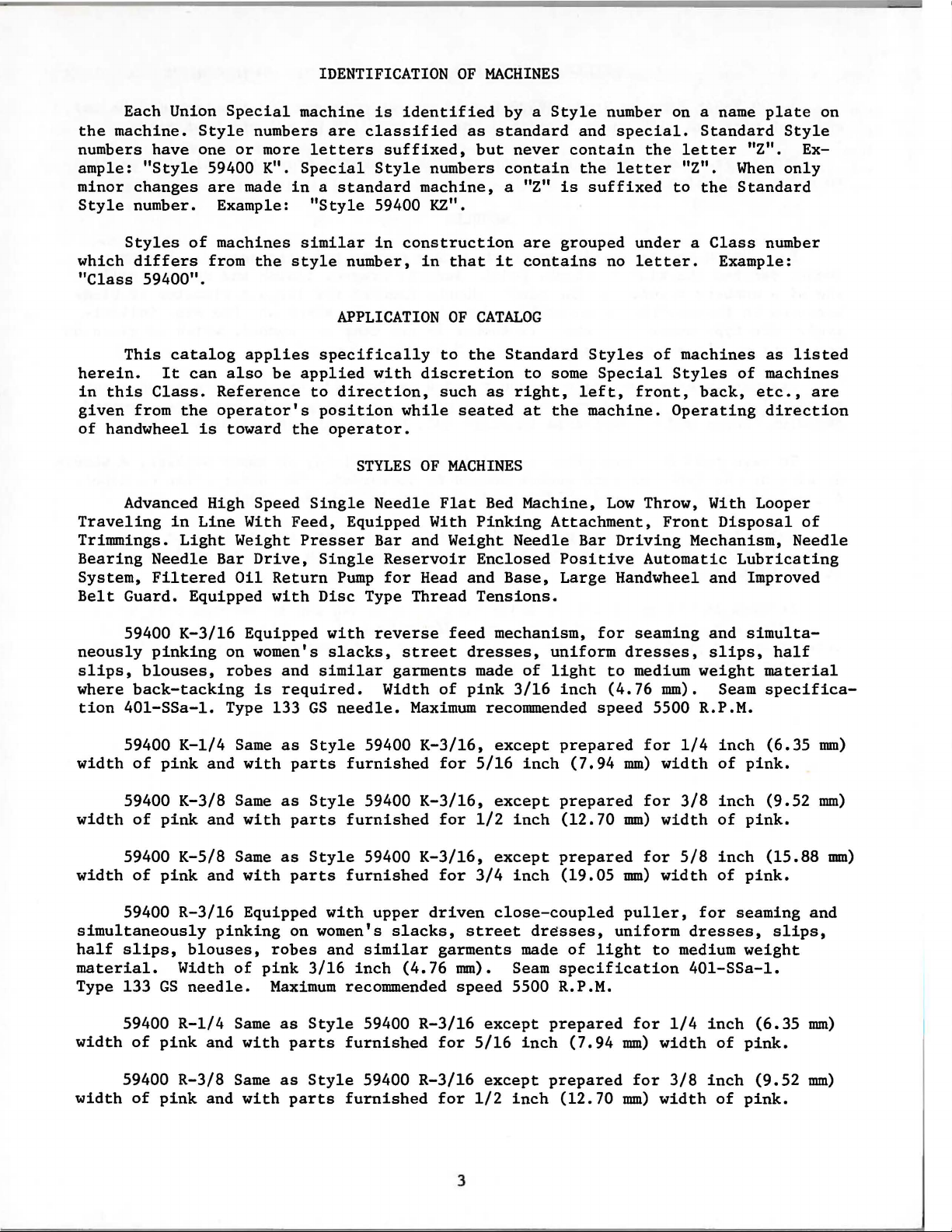
Advanced High Speed
Needle
Filtered
Guard. Equipped
Style
one
of
catalog
It
can
the
is
in
Line
Light
Special
numbers
or
more
59400 K".
are
made
machines
from
the
applies
also
be
Reference
operator's
toward
With
Weight
Bar
Drive,
Oil
Return
with
machine
are
letters
Special
in a standard
"Style
similar
style
specifically
applied
to
position
the
operator.
Single
Feed,
Presser
Single
Disc
is
classified
suffixed,
Style
59400 KZ".
in
number,
APPLICATION
with
direction,
STYLES
Needle
Equipped With
Bar and Weight
Reservoir
Pump
for
Type
identified
as
but
numbers
machine,
construction
in
that
OF
CATALOG
to
the
discretion
such
as
while
Thread
seated
OF
MACHINES
Flat
Bed
Pinking
Enclosed
Head and
Tensions.
by a Style
standard
never
contain
a "Z"
it
Standard
right,
Needle
Base,
is
are
grouped
contains
to
some
at
the
Machine,
Attachment,
Positive
Large
number on a name
and
special.
contain
the
suffixed
Styles
Special
left,
machine.
Bar
the
letter
under a Class
no
letter.
front,
Low
Throw, With Looper
Driving
Automatic
Handwheel and Improved
Standard
letter
"Z".
to
the
of
machines
Styles
back,
Operating
Front
Mechanism,
Example:
Disposal
plate
"Z".
When
Standard
number
as
of
machines
etc.,
direction
Lubricating
on
Style
Ex-
only
listed
are
of
Needle
59400
neously
slips,
where
tion
401-SSa-1.
59400
width
width
width
simultaneously
half
material.
Type 133
width
width
of
59400
of
59400
of
59400
slips,
59400
of
59400
of
K-3/16
pinking
blouses,
back-tacking
K-1/4
pink
K-3/8
pink
K-5/8
pink
R-3/16
Width
GS
R-1/4
pink
R-3/8
pink
Equipped
on women's
robes
Type 133
Same
and
with
Same
and
with
Same
and
with
Equipped
pinking
blouses,
of
needle.
Same
and
with
Same
and
with
and
is
required.
as
parts
as
parts
as
parts
on women's
robes
pink
Maximum
as
parts
as
parts
with
slacks,
similar
GS
needle.
Style
Style
Style
3/16
Style
Style
59400
furnished
59400
furnished
59400
furnished
with
and
similar
inch
recommended
59400
furnished
59400
furnished
reverse
street
garments
Width
Maximum
K-3/16,
K-3/16,
K-3/16,
upper
slacks,
(4.76
R-3/16
R-3/16
feed
dresses,
made
of
pink
for
5/16
for
1/2
for
3/4
driven
street
garments
mm).
speed
except
for
5/16
except
for
1/2
mechanism,
uniform
of
light
3/16
inch
recommended
except
except
except
close-coupled
5500 R.P.M.
inch
prepared
inch
prepared
inch
inch
Seam
(12.70
prepared
(19.05
dresses,
made
specification
prepared
inch
prepared
(12.70
(7.94
of
(7.94
for
dresses,
to
(4.76
speed
mm)
mm)
mm)
puller,
uniform
light
mm)
mm)
seaming
medium
for
for
for
for
for
weight
mm).
5500 R.P.M.
1/4
width
3/8
width
5/8
width
for
dresses,
to
medium
401-SSa-1.
1/4
width
3/8
width
and
simulta-
slips,
material
Seam
inch
of
inch
of
inch
of
inch
of
inch
of
specifica-
(6.35
pink.
(9.52
pink.
(15.88
pink.
seaming and
weight
(6.35
pink.
(9.52
pink.
half
mm)
mm)
mm)
slips,
mm)
mm)
3
Page 4
STYLES
OF
MACHINES
(Continued)
59400
width
to
number
The
measured
ively,
the
round
chromium
needle,
A
used.
stitch
of
NOTE:
point
Each Union
size
label
Standard
point,
To
complete
Selection
R-5/8
pink
of
denotes
number,
the
plated
have
or
Thread
formation.
and
Fraction
pinking
the
in
thousandths
type
of
all
needle
short,
needle
the
type
order
of
should
Same
Special
number and
needles
and
would
as
with
stamped
denotes
knife.
kind
for
double
is
orders
and
the
pass
parts
available
read:
proper
Style
needle
of
on
of
packaged
Styles
size
59400
furnished
the
has
shank,
the
needle
an
inch,
the
size
groove,
promptly
number
"1000
needle
freely
R-3/16
width
59400 K and R
in
through
of
NEEDLES
both a type
point,
shank,
midway
number
and
sold
struck
sizes
and
should
Needles,
size
except
for
3/4
pink,
length,
between
is
by
groove,
032,
accurately
be
Type 133
should
the
prepared
inch
measured
number and
groove,
denotes
the
the
complete
Union
is
Type 133
spiral
90/036,
filled,
forwarded.
be
determined
needle
eye
for
5/8
(19.05
Special.
GS,
mm)
width
from
centerline
size
number. The
finish
the
largest
shank
GS.
groove,
100/040, 110/044,
an
Use
Size
in
order
and
and
symbol,
It
empty
description
036".
by
inch
other
diameter
the
which
has a round
ball
package, a sample
the
to
produce
of
eye.
eye,
size
(15.88
pink.
of
details.
of
Collect-
is
spotted,
049,
on
of
needle
type
blade
given
shank,
054.
label.
thread
a good
mm)
on
Success
of
needles
reputation
more
than
in
the
operation
packaged
for
three-quarters
under
producing
of
Union
our
brand
highest
of a century.
name,
quality
Special
~
needles
machines
in
materials
can
,
be
secured
which
and
only
by
is
backed
workmanship
by a
use
for
4
Page 5
FILL
MAIN
RESERVOIR
HERE
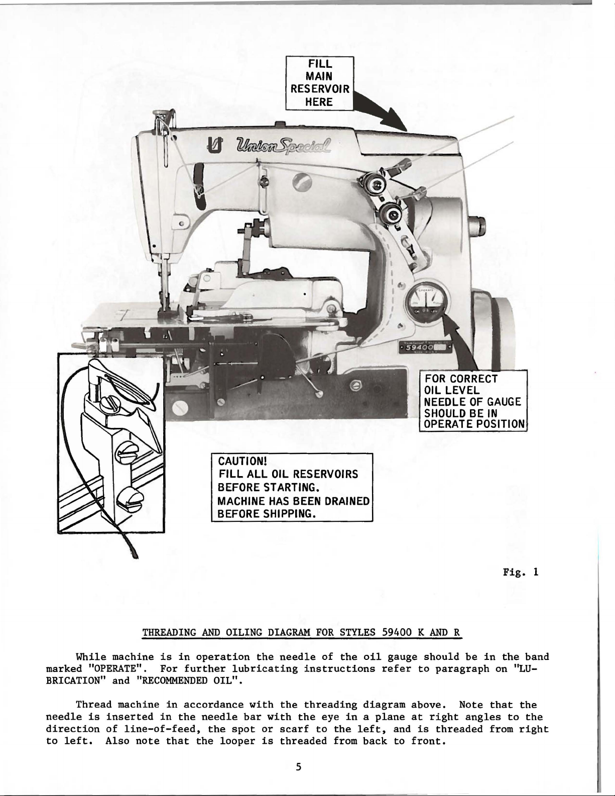
While
marked
"OPERATE".
BRICATION"
THREADING
machine
is
For
and
"RECOMMENDED
AND
in
operation
further
CAUTION!
FILL
ALL
BEFORE
MACHINE
BEFORE
OILING
lubricating
OIL".
OIL
RESERVOIRS
STARTING.
HAS
BEEN
SHIPPING.
DIAGRAM
the
needle
DRAINED
FOR
STYLES
of
the
instructions
59400 K
oil
refer
gauge
FOR
CORRECT
OIL
LEVEL
NEEDLE
SHOULD
OPERATE
AND
R
should
to
paragraph
OF
GAUGE
BE
IN
POSITION
be
in
on "LU-
Fig.
the
1
band
Thread
needle
direction
to
left.
is
inserted
of
Also
machine
in
in
line-of-feed,
note
that
accordance
the
needle
the
the
looper
bar
spot
with
with
or
is
the
threading
the
scarf
to
threaded
5
eye
in a plane
the
from
diagram
left,
back
and
to
above.
at
right
is
threaded
front.
Note
angles
that
to
from
the
the
right
Page 6
H
~~
. OIL
VAPOR
SPLASH
ACTION
OIL RESERVOIR
FEED
OIL
FROM
CRANKSHAFT
,.,
LEFT
BUSHING
k
I '
, \
\ I
~.I
BoiL
RETURN
SCREW
BY-PASS
6
WITH
OUTLET
M
Page 7

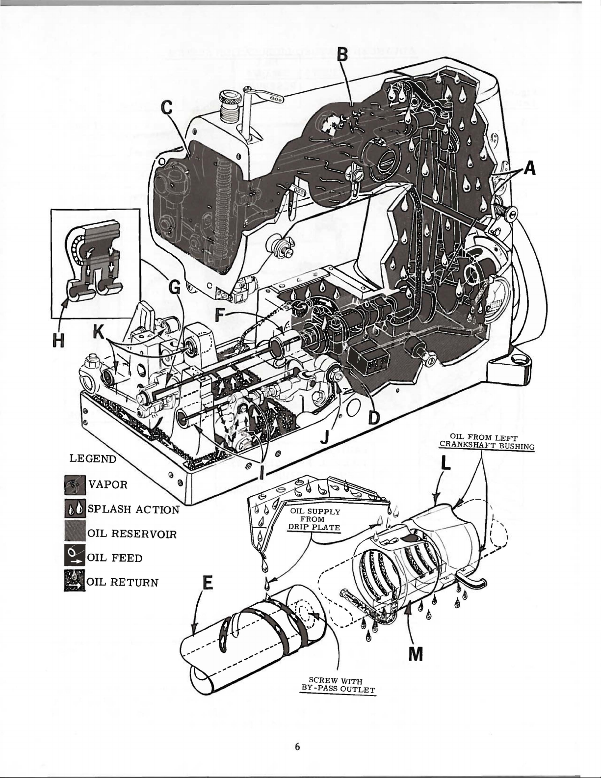
ADVANCED
FLATBED
LUBRICATION
SYSTEM
Figure
Letter
A.
B.
c.
D.
E.
F.
G.
Bearing
Crankshaft
and
Needle
Head
ings).
Looper
lever
Opposing
end
vents
s
haft
R1ght
Left
tric
or
crankshaft
lever
area
drive
bearings.
of
mainshaft.
oil
bearing.
mainshaft
main
bearings
Machine
drives,
(all
mechanisms
Helical
leakage
shaft
bearing and
located
Area
upper
bearings.
cross
crank,
shaft
grooves
Short
from
bearing.
on
SUPPLY
ball
bearing.
and
looper
in
groove
right
all
eccen-
mainshaft.
straps
bear-
drive
right
pre-
main-
SYSTEM
Method
Oil
ions
rods.
Oil
supplied
Mist
Oil
(56343
connecting
Oil
splash
Supply
shaft.
Oil
andmeteredby
troduced
right
Amount
shaft
in
of
Lubrication
agitation
on
trough
as a result
agitationas a result
E)
drip
in
grooves
supplied
controlled
right
needle
by
splash
on
bottom
rod.
plate
chamber.
from
into
mains
of
lubricant
end
of
as a result
(51282
lever
AE)
in
of
splash
of
which
in
right
hollow
felt
plugs.
center
mainshaft.
haft
with
of
bearing
of
extens-
connecting
which
column
looper
accumulates
end
shaft
in
by-pass
area.
in
column.
ofsplasher
drive
of
main-
mainshaft
Oilis
in
area.
center
hole
is
inthe
of
H.
I.
J.
K.
Figure
Letter
L.
M.
Lower
mainshaft
Looper
rocker
per
rod
Right
joint.
Feed
rocker
Machine
Head
Base
looper
rocker
shaft
ends
eccentrics.
cone,
shaft
bearings,
ball
joint.
bearings.
Area
of
connecting
right
rod
shaft
and
and
needle
and
upper
rods
left
looper
left
bearing
RETURN
of
loo-
feed
SYSTEM
Oil
run-out
supplies.
Supplied
shaft
yarn
Oil
to
lubricating
Self-lubricated
Method
Felt
pump
primed
bearing.
Feltpad
return
and
accumulates
chamber.
from
which
as a metering
supplied
of
Return
pad
in
head
located
by
oil
inbasecollects
pump
primed
from
eccentric
hollow
contains 4 strands
from
plate
bearings.
on
from
located
by
oil
splash
looper
device.
front
(56393
collects
crankshaft
left
on
drip
in
base
K).
oil.
crankshaft
oil.
crankshaft
plate
looper
bearing
rocker
of
felt
Return
and
Second
which
drive
7
Page 8
INSTRUCTIONS
LUBRICATION
FOR
MECHANICS
CAUTION!
reservoir
before
the
beginning
oil
damage.
Use a
Fahrenheit
No.
175.
check
and
is
to
the
should
zone,
28604
be
marked
R.
CAUTION!
It
extended
directly
bar.
several
ing
Replace
will
minutes
parts.
For
dirt
and
If
dirty,
commended
drained
screw
at
crank
(C,
front
chamber
machine.
Oil
must
be
to
the
various
straight
in
the
Fill
main
oil
level
black
added when
"LOW".
It
is
recommended
period
oil
be
the
head
be
required.
machines
lint
deposits
change
every
2000
from main
Fig.
of
2)
the
machine,
cover,
has
been
filled
to
operate.
to
parts.
mineral
main
reservoir.
reservoir
at
gauge (A).
line,
located
needle
The recommended
is
important
that
lubricated
needle
cover
bar
as
Run
to
distribute
in
operation
at
the
oil.
operating
reservoir
located
or
located
drained
the
proper
Run
machine
Full
RECOMMENDED
oil
of a Saybolt
This
at
plug
Oil
to
the
is
to
that
a new
link
no
machine
machine,
as
follows:
and
further
slowly
oil
to
check
reasonable
An
oil
change
hours.
by removing
below
the
by
removing
at
the
from
speed
screw
is
right
the
black
oil
these
the
hand
the
the
intervals.
Oil
cloth
back
the
level
slowly
operation
OIL
is
equivalent
in
at
maximum
of
line,
is
available
machines
or
Remove
needle
oil-
for
various
oil
is
re-
may
plug
plate
the
lower
of
main
as
indicated
reservoir
for
viscosity
upper
"OPERATE"
located
not
one
that
the
for
be
several
can
then
of
to
Union
crank
safe
operating
zone,
in
16
be
has
head
before
on
oil
gauge (A,
minutes
be
expected
90
to
125
Special
chamber
marked "FULL".
to
the
left
fluid
over
been
cover,
ounce
filled.
out
clean
shipment,
to
distribute
tithout
,.
seconds
specification
cover
level
(B,
when
of
"OPERATE"
cans
of
service
out
I
••
..---
L
---
..J
so
Fig.
at
Fig.
No.
lint
the
2)
100°
2)
needle
Oil
for
and
B
7
G
an
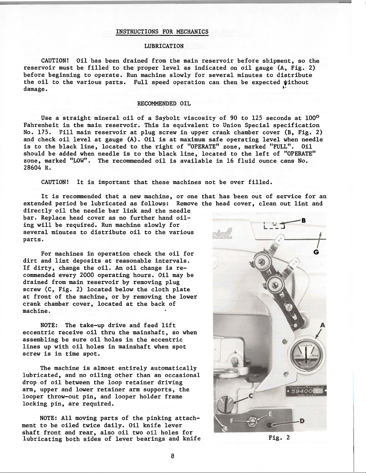
NOTE:
eccentric
assembling
lines
screw
up
is
The machine
lubricated,
drop
of
arm,
upper
looper
throw-out
locking
NOTE:
ment
shaft
to
front
lubricating
receive
be
with
in
oil
and
pin,
All
be
oiled
The
take-up
sure
oil
time
spot.
is
and no
between
lower
pin,
are
required.
moving
twice
and
rear,
both
sides
oil
oil
holes
almost
oiling
the
retainer
drive
thru
holes
in
loop
and
parts
daily.
also
of
and
the
mainshaft,
in
the
mainshaft
entirely
other
than
retainer
arm
looper
of
the
Oil
oil
two
lever
bearings
feed
lift
eccentric
when
automatically
an
occasional
driving
supports,
holder
frame
pinking
knife
oil
lever
holes
so
spot
attach-
and
8
when
the
for
knife
Fig.
2
Page 9
RECOMMENDED
OIL
(Continued)
haler
voir.
followed:
1.
2.
3.
4.
5.
6.
7.
shaft.
The
Should
Place
Remove
drain
Make
Remove
Fill
shaft
Loosen
or
right
of
"OPERATE"
Tighten
oil
gauge
an
the
the
oil
sure
lower
main
bushing
lock
until
lock
Major
machine
from
all
reservoir
pinker
is
adjustment
oil
reservoir
the
oil
crank
(D,
nut
(E) on
the
zone,
nut
set
at
upright
reservoir.
is
drained
chamber
to a level
Fig.
gauge
marked
(E) and
oiling
become
2).
calibrating
needle
points
the
factory
necessary,
on a
plug
screw
from
cover,
"LOW".
replace
OIL
level
even
GAUGE
the
located
screw
rests
plug
are
to
table
(C,
main
with
on
screw
marked
show
the
however,
or
bench.
Fig.
2) and
reservoir.
at
the
the
bottom
{F),
and
the
black
(C) and
in
RED
proper
the
back
turn
line,
on
oil
following
tip
machine
of
the
contour
the
located
lower
the
attachment.
level
machine.
of
screw
crank
in
steps
forward
the
knee
to
the
to
the
chamber
the
reser-
should
to
press
left
left
cover.
be
8.
Add
"OPERATE"
of
needle
upper
is
tilted
bed
casting
(Do
not
ance
oil
so
Remove
crank
as
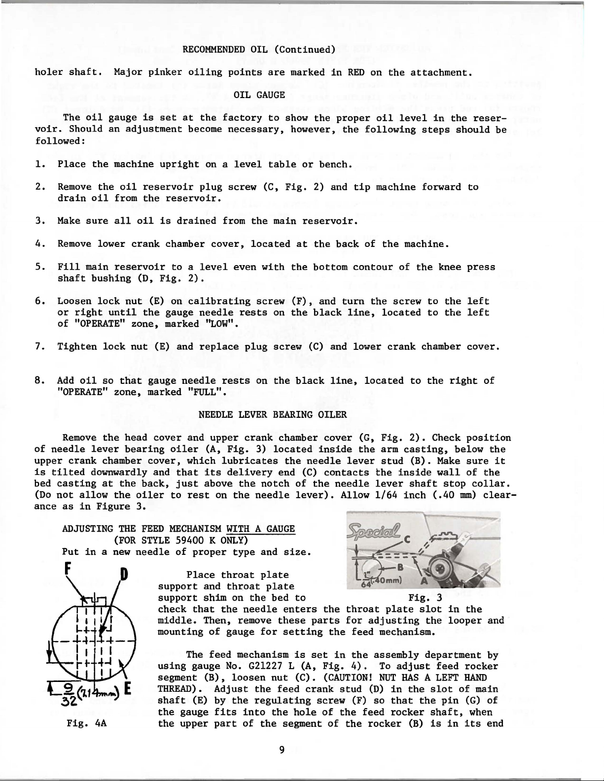
ADJUSTING
Put
Fig.
the
lever
chamber
downwardly and
at
allow
in
Figure
in a new
4A
that
zone,
head
bearing
the
the
THE
(FOR
gauge
marked "FULL".
cover,
back,
oiler
3.
FEED
STYLE
needle
needle
cover
and
oiler
which
that
just
to
rest
MECHANISM
59400 K
of
proper
Place
support
support
check
middle.
mounting
using
segment
THREAD).
shaft
the
the
that
The
gauge
(E) by
gauge
upper
rests
NEEDLE
upper
(A,
lubricates
its
above
on
ONLY)
throat
and
shim
the
Then, remove
of
feed
No.
(B),
Adjust
fits
part
on
LEVER
crank
Fig.
3)
delivery
the
the
needle
WITH A GAUGE
type
throat
on
the
needle
gauge
mechanism
G21227 L (A,
loosen
the
the
regulating
into
of
the
BEARING
chamber
located
the
end
notch
and
size.
plate
plate
bed
enters
these
for
setting
nut
feed
the
the
segment
black
OILER
needle
(C)
of
the
lever).
to
parts
is
set
(C).
crank
screw
hole
line,
cover
inside
contacts
(G,
the
lever
needle
Allow
located
Fig.
arm
stud
the
lever
1/64
~
l~~
£t.'omm)
the
throat
for
the
feed
in
the
Fig.
4).
(CAUTION!
stud
(F)
of
the
of
the
plate
adjusting
mechanism.
assembly
To
NUT
(D)
in
so
that
feed
rocker
rocker
to
the
2).
Check
casting,
(B).
Make
inside
inch
shaft
wall
stop
(.40
c
----
Fig.
3
slot
the
department
adjust
HAS A LEFT
the
(B)
slot
the
shaft,
is
feed
pin
right
position
below
sure
of
collar.
mm)
in
the
looper
rocker
HAND
of
(G)
when
in
its
of
the
it
the
clear-
and
by
main
of
end
9
Page 10
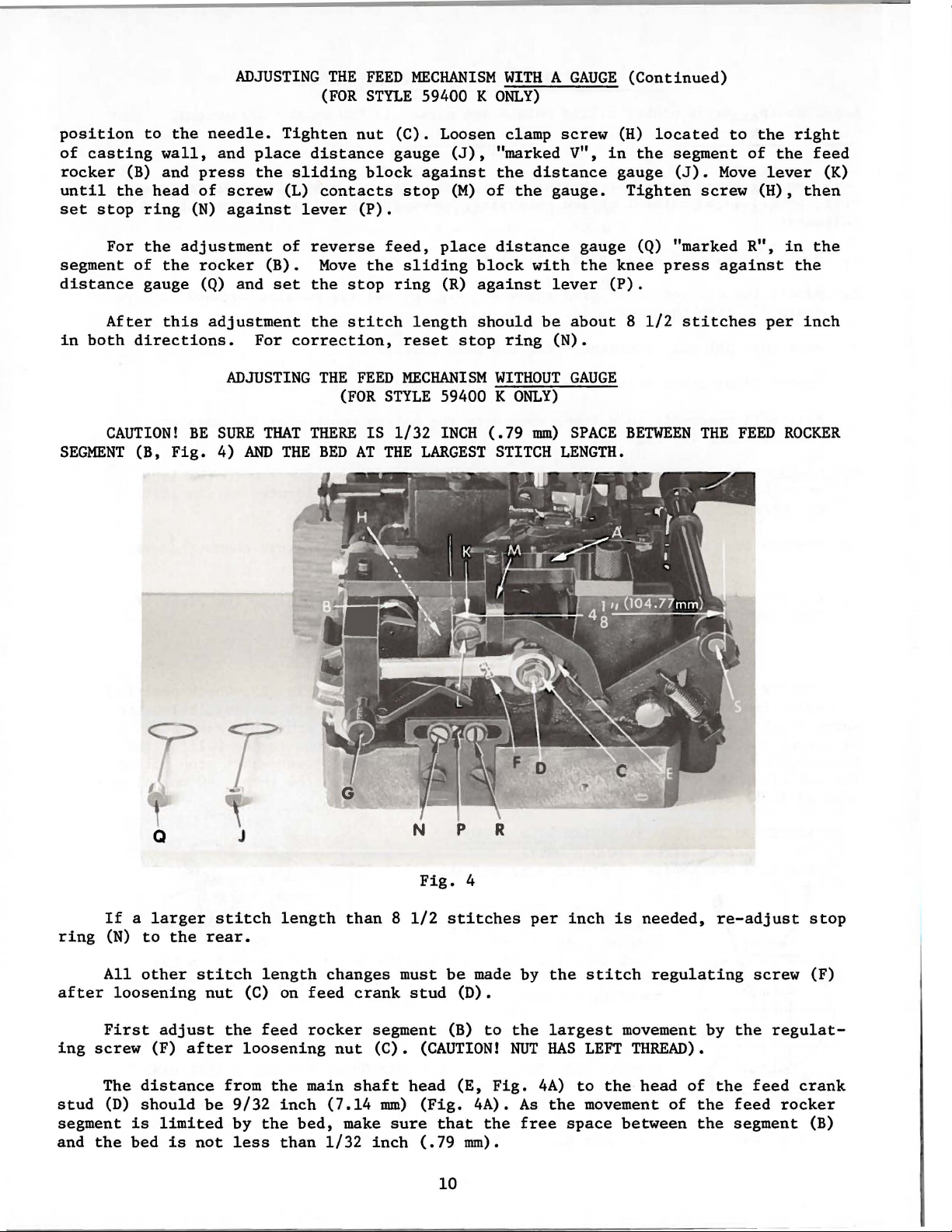
ADJUSTING
THE
(FOR
FEED
MECHANISM
STYLE
59400 K
WITH A GAUGE
ONLY)
(Continued)
position
of
casting
rocker
until
set
segment
distance
in
SEGMENT
(B)
the
stop
For
After
both
CAUTION!
to
the
needle.
wall,
and
head
ring
the
of
the
gauge (Q) and
this
directions.
(B,
and
press
of
screw
(N)
against
adjustment
rocker
adjustment
ADJUSTING
BE
SURE
Fig.
4)
place
the
(B).
For
THAT
AND
Tighten
distance
sliding
(L)
contacts
lever
of
reverse
Move
set
the
the
correction,
THE
THERE
THE
BED
nut
block
(P).
the
stop
stitch
FEED
(FOR
IS
AT
(C).
Loosen clamp
gauge
stop
feed,
sliding
ring
reset
MECHANISM
STYLE
1/32
THE
(J),
against
(M)
place
(R)
length
stop
59400 K
INCH
LARGEST
"marked V",
the
distance
of
the
distance
block
against
should
with
be
ring
WITHOUT
ONLY)
(.79
mm)
STITCH
screw
gauge.
lever
about 8 1/2
(N).
GAUGE
SPACE
LENGTH.
(H)
located
in
the
segment
gauge
Tighten
gauge (Q) "marked R",
the
knee
(P).
BETWEEN
(J).
screw
press
stitches
THE
to
the
of
Move
against
lever
(H),
per
FEED
right
the
feed
(K)
then
in
the
the
inch
ROCKER
r
p
N
Fig.
must
stud
segment
(C).
(CAUTION!
head
mm)
(Fig.
sure
inch
(.79
stitches
be
(B)
that
10
If a larger
ring
after
ing
stud
segment
and
(N)
All
First
screw
The
(D)
the
Q J
to
the
other
loosening
adjust
(F)
distance
should
is
limited
bed
is
stitch
rear.
stitch
nut
after
be
not
length
(C)
the
feed
loosening
from
9/32
by
less
the
the
length
on
feed
rocker
main
inch
bed,
than
than 8 1/2
changes
crank
nut
shaft
(7.14
make
1/32
R
4
made by
(D).
to
(E,
Fig.
4A).
the
mm).
per
the
NUT
As
free
the
largest
HAS
4A)
the
inch
stitch
LEFT
to
the
movement
space
is
needed,
regulating
movement by
THREAD).
head
of
of
the
between
the
re-adjust
screw
the
regulat-
the
feed
feed
segment
stop
(F)
crank
rocker
(B)
Page 11
(B)
is
(6.35
ing
block
this
screw
the
stop
the
lower
pin
of
For
adjusting
in
mm)
pin,
(L) and
ring
For
adjusting
5/16
its
end
diameter
and
the
set
the
the
(N)
part
of
inch
ADJUSTING
the
sliding
position
(e.g.
upper
lever
shaft
against
segment
(7.94
the
end
reverse
mm)
(FOR
to
a
drill
of
(K),
(S)
is 4 1/8
lever
(B).
diameter
THE
block
the
the
so
feed
Move
FEED
MECHANISM
STYLE
turn
needle.
of
1/4
segment.
that
the
inches
(P).
place a pin
the
and
59400 K
handwheel
Loosen
inch
When
distance
(104.77
sliding
set
the
WITHOUT
ONLY)
dia.
the
of
block
stop
GAUGE
until
screw
or
6.35
sliding
between
mm).
5/16
inch
with
ring
the
(H),
place a pin
mm
dia.)
block
outer
Tighten
(7.94
the
(R)
(Continued)
top
part
of
between
is
pressed
edges
knee
against
of
screw
mm)
press
diameter
the
the
of
the
the
(H)
against
lever
segment
1/4
inch
slid-
against
head
and
set
in
of
the
(P).
After
in
both
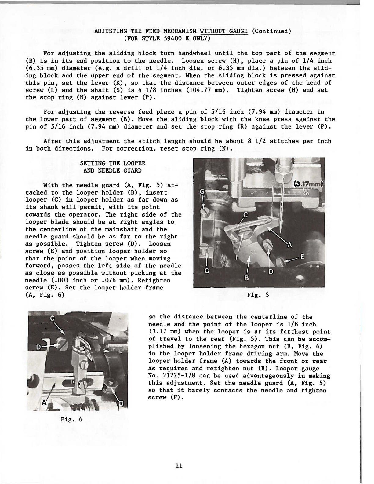
With
tached
looper
its
shank
towards
looper
the
centerline
needle
as
possible.
screw
that
forward,
as
needle
screw
(A,
(E) and
the
close
(E).
Fig.
this
directions.
the
to
the
(C)
in
will
the
operator.
blade
guard
(.003
should
should
point
passes
as
possible
inch
Set
6)
Tighten
adjustment
SETTING
AND
NEEDLE
needle
looper
looper
permit,
be
of
the
be
position
of
the
the
left
or
the
looper
the
For
correction,
THE
LOOPER
GUARD
guard
holder
holder
The
mainshaft
screw
looper
without
.076
(A,
with
right
at
right
as
far
looper
side
mm).
holder
stitch
reset
Fig.
5)
(B),
insert
as
far
down. as
its
point
side
of
angles
and
the
to
the
right
(D).
Loosen
holder
when moving
of
picking
Retighten
so
the
needle
at
frame
so
the
needle
(3.17
of
travel
plished
in
the
looper
as
required
No.
this
so
that
screw
length
at-
the
to
the
mm)
21225-1/8
adjustment.
(F).
should
stop
distance
and
the
when
to
by
loosening
looper
holder
and
it
barely
ring
between
point
the
the
holder
frame
retighten
can
Set
be
about 8 1/2
(N).
of
looper
rear
(Fig.
the
frame
(A)
be
used
the
contacts
stitches
Fig.
the
the
is
hexagon
driving
towards
nut
advantageously
needle
the
5
centerline
looper
at
its
5).
This
nut
the
(B).
guard
needle
of
is
1/8
farthest
can
(B,
arm.
Move
front
Looper
(A,
and
per
the
inch
point
be
accom-
Fig.
the
or
rear
gauge
in
making
Fig.
tighten
inch
6)
5)
Fig.
6
11
Page 12
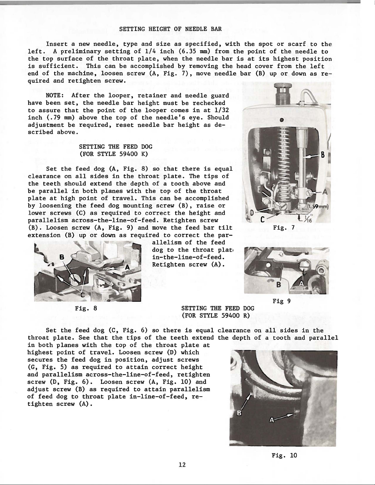
SETTING
HEIGHT
OF
NEEDLE
BAR
Insert
left.
the
is
end
quired
have
to
inch
adjustment
scribed
clearance
the
be
plate
by
lower
parallelism
(B).
extension
A
top
surface
sufficient.
of
the
and
NOTE:
been
assure
(.79
above.
Set
teeth
parallel
at
loosening
screws
Loosen
a
new
needle,
preliminary
machine,
retighten
After
set,
mm)
the
on
should
high
the
that
the
above
be
required,
SETTING
(FOR
feed
all
in
both
point
the
(C)
across-the-line-of-feed.
screw
(B)
up
of
the
This
the
needle
point
STYLE
dog (A,
sides
extend
feed
as
(A,
or
setting
throat
can
be
loosen
screw.
looper,
of
the
top
reset
THE
59400
in
the
planes
of
travel.
dog
required
Fig.
down
as
type
and
of
1/4
plate,
accomplished
screw
bar
the
of
FEED
Fig.
the
depth
with
mounting
9) and
required
(A,
retainer
height
looper
the
needle
DOG
K)
8)
so
throat
of a tooth
the
This
to
correct
move
allelism
dog
in-the-line-of-feed.
Retighten
size
as
inch
when
Fig.
and
must
comes
needle's
bar
that
plate.
top
of
can
be
screw
the
Retighten
the
to
correct
to
specified,
(6.35
by
height
(B),
the
mm)
the
needle
removing
7),
move
needle
be
rechecked
in
at
eye.
Should
as
there
is
The
tips
above
the
throat
accomplished
raise
height
screw
feed
bar
the
of
the
throat
screw
with
from
bar
the
needle
guard
1/32
de-
equal
of
and
or
and
tilt
par-
feed
plat•
(A) .
the
is
head
bar
the
point
at
spot
its
cover
(B)
or
of
the
highest
from
up
or
•
Fig.
scarf
needle
the
down
7
to th
to
position
left
as
re-
8
A
e
(
Set
throat
in
both
highest
secures
(G,
Fig.
and
parallelism
screw
adjust
of
feed
tighten
the
plate.
planes
point
the
5)
(D,
screw
dog
screw
feed
as
Fig.
to
Fig.
8
feed
dog (C,
See
that
with
of
required
6).
(B)
throat
(A).
the
travel.
dog
across-the-line-of-feed,
Loosen
as
required
the
top
in
position,
to
plate
Fig.
tips
of
Loosen
attain
screw
to
in-line-of-feed,
6)
so
of
the
screw
adjust
correct
(A,
attain
there
the
teeth
throat
(D)
Fig.
parallelism
SETTING
(FOR
STYLE
is
equal
extend
plate
which
screws
height
retighten
10)
and
re-
12
THE
at
FEED
DOG
59400
clearance
the
R)
depth
Fig
on
all
sides
of a tooth
Fig.
9
10
in
and
the
parallel
Page 13
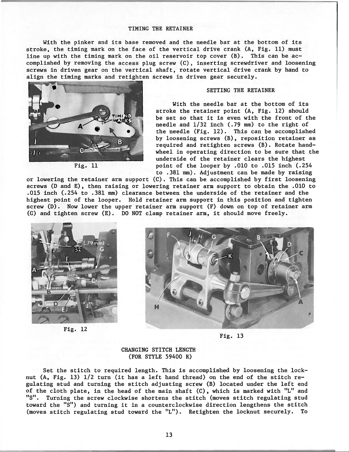
TIMING
THE
RETAINER
With
stroke,
line
complished
screws
align
or
lowering
screws
.015
highest
screw
(G)
up
inch
and
the
with
in
the
(D
point
(D).
tighten
the
pinker
timing
the
by
removing
driven
timing
Fig.
the
and
E),
(.254
of
Now
and
mark on
timing
gear
marks
11
retainer
then
to
.381
the
looper.
lower
screw
its
mark on
the
on
the
and
arm
raising
mm)
the
upper
(E).
base
the
face
the
access
vertical
retighten
support
or
clearance
Hold
retainer
DO
NOT
removed and
of
the
vertical
oil
reservoir
plug
screw
shaft,
screws
With
stroke
be
set
needle
the
needle
by
loosening
required
wheel
underside
point
to
(C).
lowering
between
retainer
clamp
of
.381
This
retainer
arm
arm
retainer
the
(C),
rotate
in
driven
the
the
so
that
and
and
in
operating
of
the
mm).
can
the
support
support
needle
drive
top
cover
inserting
vertical
gear
SETTING
needle
retainer
it
1/32
inch
(Fig.
12).
screws
retighten
the
retainer
looper
Adjustment
be
accomplished
arm
underside
(F) down on
arm,
it
bar
at
crank
(B).
screwdriver
drive
securely.
THE
bar
point
is
even
(.79
This
(B),
screws
direction
by
.010
support
of
in
this
should
the
bottom
(A,
Fig.
This
crank
RETAINER
at
the
(A,
Fig.
with
mrn)
to
can
reposition
(B).
to
clears
to
can
be
by
to
obtain
the
retainer
position
top
move
of
11)
can
be
and
by hand
bottom
12)
the
front
the
right
be
accomplished
retainer
Rotate
be
sure
the
highest
.015
inch
made by
first
the
and
of
retainer
freely.
its
must
ac-
loosening
to
of
its
should
of
the
of
as
hand-
that
the
(.254
raising
loosening
.010
to
and
the
tighten
arm
Fig.
12
Set
nut
(A,
gulating
of
the
"S".
toward
(moves
Turning
the
Fig.
stud
cloth
the
stitch
stitch
13)
and
plate,
the
"S")
regulating
1/2
turning
screw
and
to
required
turn
in
the
clockwise
turning
CHANGING
(FOR
(it
has a left
the
stitch
head
it
stud
toward
of
in a counterclockwise
STITCH
STYLE
length.
adjusting
the
shortens
the
59400
This
hand
main
"L").
13
LENGTH
R)
is
accomplished
thread)
screw
shaft
the
stitch
Retighten
(C),
direction
on
(B)
which
(moves
Fig.
13
by
the
end
located
is
stitch
the
locknut
loosening
of
the
under
marked
regulating
lengthens
securely.
stitch
the
with
the
the
left
lock-
"L"
stitch
re-
end
and
stud
To
Page 14
CHANGING
(FOR
STITCH
STYLE
LENGTH
59400
(Continued)
R)
prevent
the
"U"
The
and
lubricated
(J,
Fig.
When
directly
the
part
sealed
assemble,
grease
up
should
begins
1/8
released
position.
lease
machine
position
screw
bearings
seals
The
a good
be
The
to
inch
lever
(A)
destructive
shaped
needle
13) and remove
packing
from
number 28604
tension
stitch
barely
thread
function
(3.17
when
If
next
the
assuring
key
once a year.
the
start
to
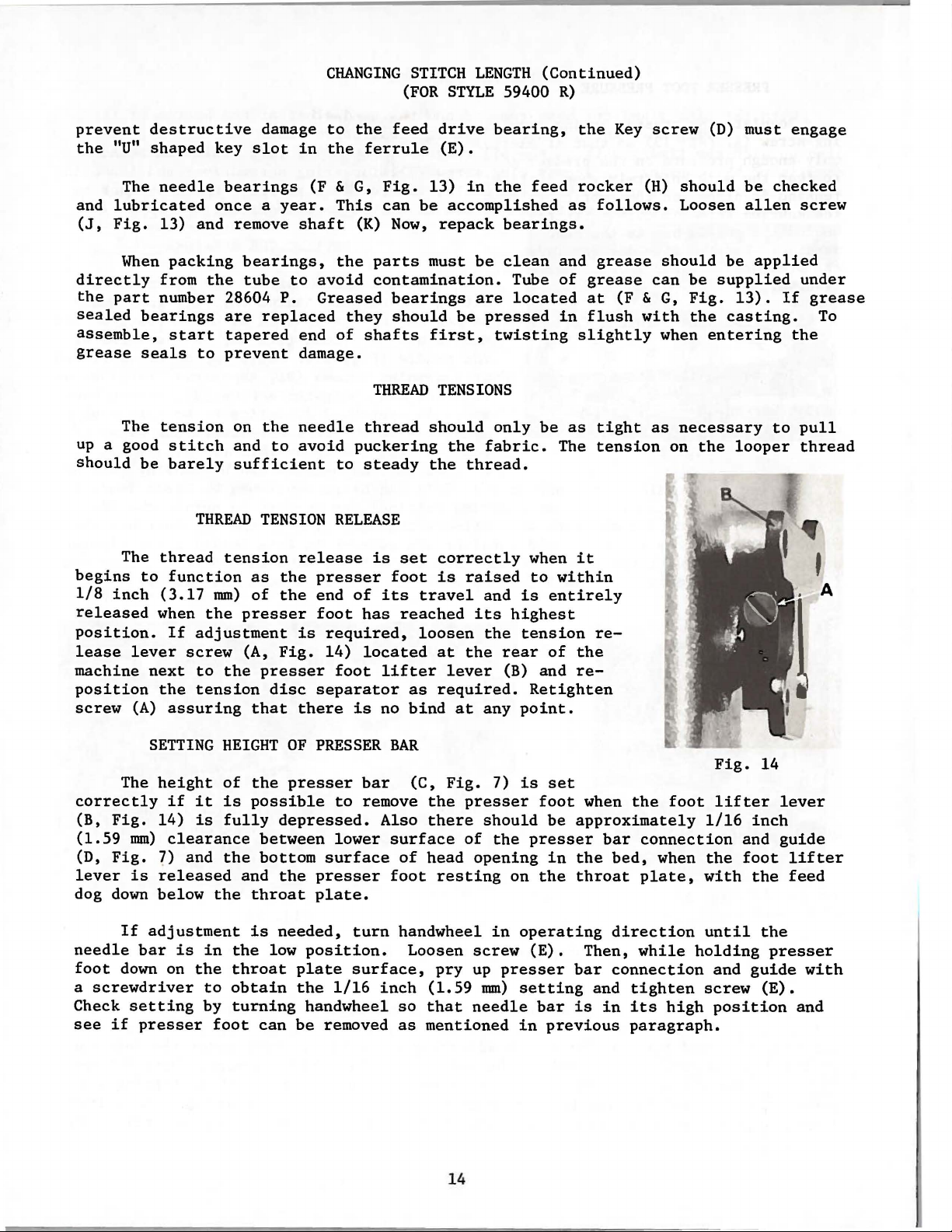
THREAD
mm)
the
adjustment
screw
to
tension
slot
bearings
bearings,
tube
are
tapered
prevent
on
and
sufficient
tension
as
of
presser
(A,
the
that
damage
in
(F &
shaft
to
avoid
P.
Greased
replaced
end
damage.
the
needle
to
avoid
TENSION
release
the
presser
the
end
foot
is
Fig.
presser
disc
separator
there
to
the
the
ferrule
G,
Fig.
This
of
RELEASE
required,
14)
foot
can
(K)
the
parts
contamination.
they
shafts
THREAD
thread
puckering
to
steady
is
of
its
has
located
lifter
is
no
feed
Now,
bearings
should
foot
drive
(E).
13)
be
accomplished
repack
must
first,
TENSIONS
should
the
the
set
correctly
is
travel
reached
loosen
at
lever
as
required.
bind
in
be
are
be
pressed
fabric.
thread.
raised
and
its
the
the
at
any
bearing,
the
feed
bearings.
clean
Tube
located
twisting
only
be
when
to
is
entirely
highest
tension
rear
of
(B) and
Retighten
point.
the
rocker
as
follows.
and
grease
of
grease
at
in
flush
slightly
as
tight
The
tension
it
within
rethe
re-
Key
(F &
with
screw
(H)
Loosen
should
can
G,
when
as
necessary
on
(D) must
should
be
be
supplied
Fig.
the
entering
the
be
checked
allen
applied
13).
casting.
to
looper
engage
screw
under
If
grease
To
the
pull
thread
The
correctly
(B,
Fig.
(1.59
(D,
lever
dog
needle
foot
a
Check
see
mm)
Fig.
is
down
If
bar
down
screwdriver
setting
if
SETTING
height
if
it
14)
is
clearance
?)
and
released
below
adjustment
is
in
on
the
to
by
presser
HEIGHT
of
the
is
possible
fully
the
and
the
throat
is
the
throat
obtain
turning
foot
OF
PRESSER
presser
depressed.
between
bottom
the
presser
plate.
needed,
low
position.
plate
the
handwheel
can
be
bar
to
remove
Also
lower
surface
turn
surface,
1/16
removed
inch
BAR
(C,
Fig.
the
there
surface
of
head
foot
resting
handwheel
Loosen
pry
(1.59
so
that
as
mentioned
14
7)
presser
should
of
the
opening
on
in
screw
up
presser
mm)
needle
is
set
foot
when
be
approximately
presser
in
the
the
throat
operating
(E).
setting
bar
in
Then,
bar
is
previous
the
bar
connection
bed,
plate,
direction
while
connection
and
tighten
in
its
paragraph.
foot
when
high
Fig.
lifter
1/16
and
the
foot
with
until
holding
and
screw
position
14
lever
inch
guide
the
the
presser
guide
(E).
lifter
feed
with
and
Page 15
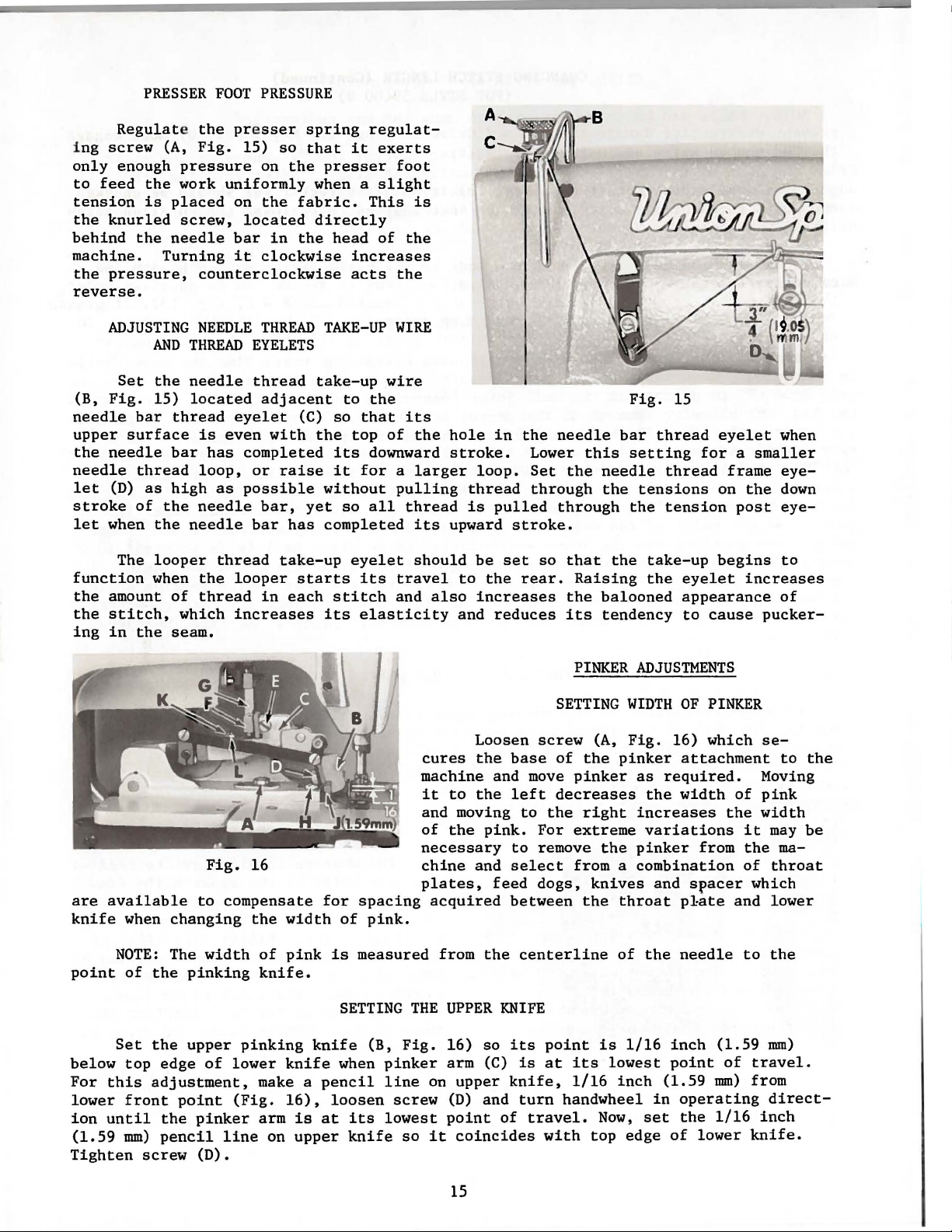
PRESSER
Regulate the pre
i ng
screw
only
enough
to
feed
the
tension
the
behind
machine.
the
reverse.
is
knurled
the
pressure,
FOOT
(A,
Fig.
15)
pressure
work
uniformly
placed
screw,
needle
Turning
on
located
bar
it
counterclockwise
PRESSURE
sser
spring
so
that
on
the
presser
when a
the
fabric. This
directly
in
the
clockwise
regulat-
it
head
increases
acts
exerts
foot
slight
is
of
the
the
A
C
~~
~~1~
D
ADJUSTING
Set
(B,
Fig.
needle
upper
the
needle
needle
let
(D)
stroke
let
when
The
function
the
amount
the
stitch,
ing
in
are
available
knife
when
AND
the
15)
bar
thread
surface
bar
thread
as
high
of
the
the
looper
when
of
the
seam.
changing
NEEDLE
THREAD
needle
located
is
has
loop,
as
needle
needle
thread
the
thread
which
Fig.
to
THREAD
EYELETS
thread
adjacent
eyelet
even
completed
or
possible
bar
looper
increases
16
compensate
the
with
raise
bar,
has
take-up
in
each
width
(C)
starts
TAKE-UP
take-up
to
so
the
top
its
it
without
yet
so
completed
eyelet
stitch
its
for
of
WIRE
wire
the
that
its
of
the
downward
for a larger
pulling
all
thread
its
should
its
travel
and
also
elasticity
cures
machine
it
and moving
of
necessary
chine
plates,
spacing
pink.
acquired
hole
stroke.
loop.
thread
is
pulled
upward
be
to
the
increases
and
reduces
Loosen
the
and
to
the
the
pink.
and
feed
in
the
Lower
Set
through
stroke.
set
rear.
base
move
left
to
to
select
between
needle
the
through
so
that
Raising
the
its
PINKER
SETTING
screw
of
pinker
decreases
the
right
For
extreme
remove
from a
dogs,
the
bar
this
needle
the
the
balooned
tendency
WIDTH
(A,
Fig.
the
pinker
the
knives
throat
Fig.
15
thread
setting
thread
tensions
the
tension
take-up
the
ADJUSTMENTS
as
required.
the
increases
variations
pinker
combination
and
eyelet
for a smaller
on
begins
eyelet
appearance
to
cause
OF
PINKER
16)
which
attachment
width
from
spacer
p1ate
frame
the
post
increases
pucker-
se-
Moving
of
pink
the
width
it
may
the
of
which
and
when
eye-
down
eye-
to
of
to
be
ma-
throat
lower
the
NOTE:
point
Set
below
For
this
lower
ion
until
(1.59
Tighten
mm)
The
of
the
the
top
edge
adjustment,
front
the
pencil
screw
width
pinking
upper
of
point
pinker
(D).
pinking
lower
(Fig.
line
of
pink
knife.
knife
make a
16),
arm
is
on
upper
is
SETTING
knife
when
pencil
loosen
at
measured
(B,
pinker
line
screw
its
lowest
knife
THE
Fig.
so
from
UPPER
16)
arm
on
upper
(D)
point
it
coincides
the
KNIFE
so
{C)
and
of
its
knife,
centerline
point
is
at
turn
handwheel
travel.
with
15
its
1/16
top
of
is
1/16
lowest
inch
Now,
edge
the
inch
point
(1.59
in
set
of
needle
(1.59
of
mm)
operating
the
1/16
lower
to
the
mm)
travel.
from
direct-
inch
knife.
Page 16

SETTING
THE
UPPER
KNIFE
(Continued)
NOTE:
When
Grind
edges
asmuch
of
the
It
back
of
Generally
is
sharpened.
ball
very
(A,
the
the
stud
Fig.
lower
lightly
"V".
upper
tighten
contact
knife.
obtain
edges
(J)
securely.
has
been
Knife".
Knife
resharpening
the
ends
should
be
as a rough
lower
knife.
should
the
knife.
(F)
to
16)
allowing
knife
so
Grind
knife
of
the
so
Now
equal
the
is
lower
the
gently
spacing
opening
removed from
can
be
the
of
the
knife
stoned
be
the
When
keen
or
burred
noted,
Do
not
lower
resharpening
disconnect
removal
(J).
The
only a slight
top
surface
positioned
knife
point
of
holding
the
press
between
of
the
Replace
pinker
the
sharpened
upper
only.
and
smooth,
edge
also,
that
change
SETTING
knife
the
does
ball
of
knife
may
amount
only.
so
that
screws
upper
the
lower
the
lower
on
pinker
on
knife,
DO
will
the
this
THE
not
is
necessary,
joint
the
pinker
be
of
When
its
knife
knife
cutting
knife.
the
machine
base
both
do
NOT
free
not
ends
ends
not
GRIND
from
last
of
angle.
LOWER
require
connection
attachment.
sharpended
metal
replacing
holding
(J)
securely.
is
just
moving
edges
Now
after
and
its
and
can
destroy
THE
SIDES.
all
long
and
the
knife
KNIFE
sharpening
loosen
on
is
removed.
the
screw
is
below
it
to
of
the
tighten
assuring
support.
be
the
burrs.
may
screw
rod
the
lower
at
Bring
the
right
upper
the
Recheck
reversed.
"V"
After
This
damage
are
on
every
(E,
assembly
Remove
side
of a wheel.
DO
NOT
knife
the
top
the
top
surface
or
knife
lower
that
shape
grinding,
is
the
an
angle
time
Fig.
(G).
screws
grind
be
of
cutting
left
as
and
knife
all
"Setting
of
the
important
cutting
with
the
upper
16)
and
Remove
(H)
which
Touch
the
sure
its
that
slot.
edges
of
the
required
the
inside
holding
foreign
The Upper
knife.
the
in-
edge
the
knife
back
screw
inside
the
Do
into
lower
to
screws
matter
out
hold
it
of
not
The
screw
(K,
cutting
is
to
be
necessary
driven
shaft
tion
gear
to
of
pressure
Fig.
16)
clean,
noted
a
that
to
obtain a clean
(B).
obtain
this
shaft
applied
which
slight
to
Fig.
While
desired
is
SPRING
is
increase
insure
on
locked
cut
PRESSURE
the
cutting
in
of
long
knife
should
8
ON
edges
position
pressure
life,
be
used.
UPPER
will
when
its
inch
the
this
various
timing,
cover
the
facilitate
17 (A,
holding
timing
not
changed
the
of
the
while
handwheel,
upper
knife.
making
KNIFE
is
controlled
by
nut
generally
only
the
The
the
upward
(1.59
lower
timing
located
machine.
Fig.
advance
Be
this
adjustment.
by
(L).
If
the
remedy
minimum amount
TIMING
machine
point
should
of
THE
the
travel)
mm)
above
knife.
may
types
remove
improve
of
work.
the
on
the
Slight
Rotate
loosening
17)
in
the
or
retard
careful
that
the
Allen
knives
the
fault.
of
PINKER
start
upper
is
approximately
the
top
variations
the
To
upper
top
crank
right
handwheel
of
screws
hub
of
the
pinker
the
Be
certain
Socket
are
not
pressure
to
feed
knife
surface
operation
obtain
chamber
end
slightly
the
pinker
drive
lateral
that
It
(in
1/16
of
of
on
this
of
posi-
both
16
Page 17

TIMING
THE
PINKER
(Continued)
screws
ion
should
The
the
main
the
puller
adjusted
not
build
enough
This
to
puller
adjusted
can
reposition
tighten
(A)
are
take
puller
feed
drive
to
do most
up
upper
be
accomplished
driving
screws
Fig.
by
the
securely
place
ADJUSTING
mechanism
dog
starts
eccentric
between
feed
roller
the
connecting
segment
(A
and
18 mechanism. The
following
while
of
the
B).
tightened
machine
PULLER
must
to
feed.
located
the
feeding
presser
travel
by
loosening
link
lever
roller
mately
bracket
screw
(G)
spring
vent
tension
(B).
the
overthrow.
and
feed
pressure
pressure
method:
before
MECHANISM
be
timed
This
on
so
foot
to
keep
(C)
(E)
as
With
presser
3/16
casting.
(G)
securely.
The
(A,
the
on
The more
more
cause
by
overcoming
is
required
"Clutch
roller
pressure
of
can
running
feeding.
(FOR
to
start
can
be
the
mainshaft.
when
and
puller
reposition
the
the
screw
in
the
bar
inch
Fig.
the
spring
the
The
roller
the
be
sewing
the
material
(A,
mechanism
(4.76
Brake"
19)
from
spring
inside
proper
checked
the
machine.
STYLE
its
accomplished
puller
Fig.
clutch
to
obtain
collar
Adjustment
collar
has
overthrowing
is
nut
is
exerted
to
the
59400
feeding
The
at
slow
rollers.
taut
18)
driving
in
(F,
mm)
above
is
set
just
regulated
is
tightened
pressure
backspring
clutch
spring
and
R)
by
puller
speed
when
and/or
segment
desired
its
Fig.
the
can
be
as
required,
properly
enough
on
the
can
NOTE:
cycle
advancing
down
18)
or
with
at
mechanism
the
There
sewing
shoulder
amount
position,
should
feed
made by
when
pressure
backfeeding.
nut
to
compress
roller
become
No
cutting
the
same
or
should
material
should
at
slow
screw
lever
roller
retighten
(D)
of
feed,
be
loosening
the
on
and
to
prevent
too
excessive
act-
time
retarding
be
does
be
just
speed.
(B)
or
re-
the
feed
approxi-
mounting
screw
tension
it
to
pre-
The
locknut
the
spring
Raise
screw
plate
machine
as
the
rotate
seconds
er
does
nuts
tension
obtained.
the
to
obtained.
(B,
same
compress
the
(H,
Fig.
(K).
in
running,
screw
90°
in
with
not
Fig.
on
the
If
procedure
clutch
18).
Now
run
hole
direction
the
have
19)
spring
the
the
spring
off
Remove
the
machine
pick
or a pencil
roller
any
should
roller
except
out a point
of
in
movement
be
until
moves
until
the
lower
stop
line.
feed
the
under
loosened
the
too
the
nuts
the
roller
screw
full
speed;
on
This
in
approximately
up
position.
full
and
proper
fast,
should
proper
(J)
from
the
point
speed,
reset
setting
then
be
setting
17
and
loosen
support
while
roller
should
If
the
with
is
follow
tightened
is
the
3
then
such
to
roll-
the
less
4
Fig.
19
Page 18

ADJUSTING
PULLER
MECHANISM
(FOR
STYLE
59400 R
Continued)
CAUTION!
Fig.
pull
stroke.
dering
position
quired
19)
are
Should
the
(C,
Fig.
The
the
loopers
released
ILLUSTRATIONS
This
sections
ing
of
material
19)
looper
By
tilting
catalog
repair
of
in
the
parts
in
the
more
easier.
pulling
the
the
The
machine
locked
clockwise
parts.
particular
together
or
less
through
frame
looper
the
ORDERING
has
mechanism
machine.
with
and/or
pressure
uniformly,
to
increase
throw-out
It
can
throw-out
loopers
REPAIR
been
arranged
Exploded
are
On
their
view
clutch
even
during
on
LOOPER
(Fig.
be
used
forward.
PARTS
views
shown
the
page
part
number,
being
should
the
the
upper
turn
pressure
FRAME
THROW-OUT
20)
only
when
actuating
to
simplify
of
various
so
that
opposite
description,
shown.
never
adjusting
puller
the
feed
or
counterclockwise
is a convenience
the
pin
or-
the
parts
the
be
of
roller
roller
needles
(A),
the
may
illustration
and
run
unless
the
mechanism
presser
used
are
looper
be
seen
the
both
machine.
spring
to
decrease.
to
make
at
the
holder
Fig.
in
will
number
be
be
threading
top
their
found a
of
pieces
nuts
regulator,
of
20
(B,
required
their
frame
is
actual
listre-
to
of
Numbers
position
ordering
Component
dicated
bly.
not
commended,
in
only
by
Example:
Ref.
No. No.
41 29476
42 22894
43
It
will
listed.
At
the
this
book.
the
in
of
that
parts.
indenting
be
The
so
back
part
number
the
parts
Part
noted
the
This
first
part
Always
77
reason
of
in
of
their
MK.-080
AA
in
complete
the
will
is
column
the
use
sub-assemblies
descriptions
the
is
that
sub-assembly
book
facilitate
known.
are
illustration.
the
part
Description
Feed
for
Spot
Screw
example shown
replacement
will
be
IDENTIFYING
reference
number
which
under
Lift
Styles
locating
Eccentric
Screw
-------------------------------
should
found a
numbers
Reference
listed
can
be
the
description
59400 K
above
of
that
these
be
ordered.
numerical
the
illustration
PARTS
in
furnished
Assembly,
and R --------------
parts
only,
numbers
the
second
the
eccentric
individually
index
and
merely
should
column.
for
of
the
of
all
and
indicate
never
repairs
main
be
are
sub-assem-
Amt.
~
1
1
and
bearing
is
the
parts
description
not
used
in-
are
re-
shown
when
the
in
Where
some
identification
appear.
of
Part
the
the
smaller
numbers
construction
parts,
letter
is
represent
permits,
and on
stamped
the
those
in
same
each
where
to
distinguish
part,
18
part
is
the
regardless
stamped
construction
the
of
part
the
with
from
its
does
similar
catalog
part
not
in
number.
permit,
ones.
which
On
and
they
Page 19

IDENTIFYING
PARTS
(Continued)
IMPORTANT I ON
WHICH
Union
it
approved
ciency
parts
trademark
are
wise
a
driver,
of
PART
Success
Special
subsidiaries
and
Genuine
are
Prices
forwarded
directed.
Torque
distance
torque
IS
ORDERED.
in
Needles
scientific
durability
needles
stamped
is
your
are
f.o.b.
(measured
by a lever
etc.
Many
will
ALL
ORDERS,
USE
GENUINE
the
operation
and
Repair
and
authorized
principles,
are
assured.
are
packaged
with a reproduction
guarantee
net
cash
A
charge
of
tighten
shipping
in
(in
these
of
and
are
is
made
inch-pounds)
inches
devices
the
part
PLEASE
of
distributors.
and
the
point.
TORQUE
to
INCLUDE
NEEDLES
these
Parts
are
with
of
highest
TERMS
subject
Parcel
to
cover
REQUIREMENTS
is a rotating
or
feet).
are
the
PART
AND
REPAIR
machines
as
furnished
They
made
with
labels
available,
correct
the
familiar
quality
to
change
Post
postage
This
marked
NAME
AND
PARTS
can
be
secured
by
the
Union
are
designed
utmost
in
without
shipments
and
is
accomplished
which when
amount and no
precision.
~
Union
materials
insurance.
force
notice.
(in
STYLE
only
Special
according
•
Special
and
are
insured
pounds)
by a
set
at
tighter.
OF
MACHINE
with
Genuine
workmanship.
All
the
genuine
Corporation,
to
Maximum
trademark.
shipments
unless
applied
wrench,
proper
FOR
the
effi-
repair
Each
other-
through
screw
amount
most
All
unless
by hand
The
straps
otherwise
as
tightly
screws
and
eccentrics
noted.
as
possible,
requiring
All
a
should
other
unless
specific
be
nuts,
torque,
tightened
bolts,
otherwise
will
to
screws,
noted.
be
indicated
19-21
etc.,
inch-pounds
should
on
be
the
(22-24
tightened
picture
em/kg)
plates.
19
Page 20

FILL
MAIN
RESERVOIR
CAUTION'
Fill
oil
before
re~ervo
start
Machine
dr~ined
sh1ppin
beforeeen
g.
i
r
·
has1~g.
20
Page 21

MAIN
FRAME,
AND
NEEDLE
MISCELLANEOUS
THREAD
COVERS
TAKE-UP
WIRE
Ref.
No.
Part
No.
1 22829
2
3
4
21375
98
52
AV
A
A
5 56391
6 22539 R
7 52958 B
8 22848
9
20
10 539
11
12
22889 A
95
13 22513
14 35731 A
15
16
17
18
19
20
21
22
23
24
25
26
27
28
29
30
31
32
33
34
35
36
37
38
660-342
51294
R
7947
56393
c
56393 D
22585
22569
c
56382
56382 N
357
57882 E
51270 B
95
63494 B
22894 E
51282
52882
AE
y
56382 w
90
56382 c
56382 B
22541 c
22733 E
56382 M
39 56382 E
40
41
42
43
44
45
46
47
56382 D
22548
56382
L
56382 F
22848
56382 K
56382 J
22829
Description
Screw - - Belt
Guard
Screw - - Looper Thread
Looper Thread
Plug
Screw Looper Thread
Eyelet
Guard - -
Eyelet
- - - -
Screw - - - Washer- - - - - - - - Needle
Adapter
Plug
Thread Frame
Eyelet
Screw - - -
Screw - - - - - - - Screw - - Presser
Bar
Connection
Guide
Plate
Screw - - Nut - - - -
Head
Oil
Tube Mounting Block
Head
Oil
Tube Clamp - - - - - Screw - - - - - - - - - - - - Screw - - - - - - - -
Head Cover - - - - - - - Head Cover
Gasket
Screw - - - - - - - -
Oil
Drip
Needle
Plate
Thread Take-up Wire - - - - -
- - -
Screw - - - - - -
Plug
- - - - - - - - - - - -
Screw - - - - - - - - - - -
Needle
Baffle
Underarm
Lever
Plate
Drive
Bearing
Oiler
- - - - - - Shaft
Oiler
Screw - - Gasket
Upper Crank Chamber Cover - - - -
Screw - - Oil
Filler
Gasket
Gasket
Crank Chamber Cover,
Plug
- - - -
Screw -
- - - - - - - - - - lower
Screw - - - Gasket
Oil
Reservoir
Back Cover
Screw - - - Gasket
Looper
Drive
Shaft
Reservoir
Cover
Screw - - - - - - - - - - - - - - - -
Arnt.
Req.
- - - - 2
1
- - - - 3
- - - - - - - - - - - 1
- - - - 1
1
- - - - - 1
- - - - - - - - - 1
- - - - 1
1
1
1
3
- - - -
- - - - - - - - 1
- - - - - 2
- - - - - 1
- - - - - - 2
- - - - 2
- - - - 1
- - - - - 1
2
- 1 Lock Washer - - - - - - - - - - - - - -
1
1
1
1
1
- 1
1
1
1
1
1
2
1
- - - - 4
- - 1
- - - - 1
1
1
- - - - 4
1
- - - - - - - - - 1
- - - - - - - - 9
- - - - - 1
- - - - - 1
- - - - - - - - - 2
21
Page 22

22
Page 23

MAIN
FRAME,
BUSHINGS,
HEAD
OIL
AND
GAUGE,
BASE
MISCELLANEOUS
OIL
PUMPS
OILING
PARTS,
Ref.
No.
1
2
3
4
5
6
7
8
9
10
11
12
13
14
15
16
17
18
19
20
21
22
23
24
25
26
27
28
29
30
31
32
33
34
35
36
37
38
39
40
Part
No.
59493 A
666-214
52883 R
59484
K
21657 X
59484 H
35761 D
56390 E
56390 B
22569 B
63494
K
63494 F
63494 G
660-455
56394 B
660-221
11635 B
56394 A
426 B
59494
27-527
61494 G
604
56390
59451
A
A
56393 Q
59436
56393
X
51254 A
50-895
56390
56336 H
59435 B
57836 B
51257
AA
56354 B
56190
56393 T
56393 L
51154 E
56393 R
Blk.
Blk.
Description
Base
Oil
Pump
Assembly - - - - -
Intake
Presser
Pinker
Tension
Pinker
Pinker
Bushing
Crankshaft
Felt
Foot
Drive
Release
Drive
Shaft
Housing
Bushing
- - - - - - - - - -
Lifter
Shaft
and
Shaft
Bushing
Gasket
Screw - - - - - - - Oil
Gauge Assembly
Nut - - - - -
Oil
Oil
Spring
"O"
Gauge
Retaining
Washer - -
Ring - - -
Connecting
Ring - - - Nut - - - - - - - Oil
Oil
Gauge
Pin
Gauge
Adjusting
- - - - - - - - - Float
Lever
Washer - - - -
Collar
-
Screw - - Main
Loop
Shaft
Retainer
Machine Base
Looper Rocker
Machine Base
Looper
Looper
Main
Shaft
Lever
Feed
Rocker
Feed Rocker
Presser
Needle
Main
Head
Shaft
Oil
Intake
Needle
Oil
Attraction
Bushing,
Felt,
Felt,
Throw-out
Rocker
Bushing,
Bushing
Shaft
Shaft
Bar
Bushing,
Bar
Bushing,
Bushing,
Pump
Felt
Bar
Bushing,
Drive
rear
Shaft
Actuating
Shaft
- - - - - - - - - - - - - Bushing,
Bushing,
Assembly - - - - - - - - - - - -
- - - - - - - - - - -
Felt
Lever
Bushing,
Lifter
Bushing,
Cap,
Bushing
left
Lever
right
plastic
- - - -
Shaft
- - - - 1
Bushing
- - - - - -
Housing - - - - - - - - -
- - - - - - - - - 1
Rod
- - - - - - - - - 1
Shaft
-
Assembly
right
Crank
Bushing
- - - - - - -
Bushing,
front
Bushing,
left
lower
lower
middle
upper
right
- - - - - - - - - Pin
Bushing
left
- - - - - - - for
for
Style
Style
59400 K
59400 R
-
- - -
- - - - - - - -
- - - - - - - - - -
- - - - - - - - - - - - - -
Amt.
Req.
1
1
- - - - 1
- - - 2
1
- - - - - 1
1
- - - - 1
3
- - - - 1
1
1
1
1
1
1
1
1
- - - - 1
1
1
1
1
1
1
- - - - 1
- - - - - 1
- - - - 1
1
- - - - 2
- - - - 2
1
1
1
- 1
1
1
- 1
23
Page 24

Torque
24-26in,
,~(28-30om.
to
lbs.
kg.)
25 26
3
24
Page 25

CRANKSHAFT,
NEEDLE
LEVER,
NEEDLE
BAR
AND
PULLEY
Ref.
No.
1
2
3
4
5
6
7
8
9
10
11
12
13
14
15
16
17
18
19
20
21
22
23
24
25
26
27
28
29
30
31
32
33
34
35
36
37
38
39
40
41
42
43
44
45
46
47
48
49
Part
No.
22768
56358 A
54417
A
22819
27-435
56358
22768
22586 R
51250 F
51250
D
660-212
51150
29348
y
77
51054
666-149
51254
J
22562 A
56354 A
22564
56315
56350 A
29066
R
22559 G
51216 N
51216
p
56316
29476
MD
51216 M
56316
c
12934 A
57821 A
22574
61321 L
57821
56321
22894
H
AB
660-202
59484 D
98
59451 R
98
29133
M
22768
22894
c
54195
98
Blk.
Description
Screw - - - - - - Needle
Needle
Lever
Thread
Bar - - - -
Eyelet
Screw - - - - - - - - Needle
Needle
Bar
Eyelet
Bar Thread
Washer
Eyelet
Screw - - Screw - -
Gasket
- - - -
- - - - - - - - - - - - 1
Washer - - - - - -
Oil
Seal
Ring - - - - - Needle
Needle
Lever
Lever
Thrust
Collar
Assembly
Screw - - - - - - - - -
Link
Needle
Pin
Felt
- - - -
Wick - -
Bar
Connection
-
Screw - - - -
Needle
Bar
Link
- -
Screw - - - - - Needle
Needle
Needle
Lever
Lever
Lever
Connecting
- - - -
Stud
Rod
Upper
Assembly - -
Screw Washer - - Nut - - - - Needle
Crankshaft
Connecting
Lever
Needle
Connecting
Assembly,
bearing
Rod
Guide - - - - - - - - -
Rod
-
.910
inch
- - - - - - - - -
throw
Nut - - - - - - - Handwheel Assembly
Screw - Retaining
Plate
- - - Handwheel
Pulley
-
Screw -
"O"
Ring - - - -
Pinker
Feed
Drive
Sprocket
Screw - - - - - - -
Head
Base
Loop
Oil
Pump
Retainer
Assembly, (See
Assembly, (See
Drive
Gear - - -
Ref.
Ref.
Oil
Pump
Screw - - - - - - - - - - - -
Looper
Drive
Eccentric
Assembly -
Screw - - - - - - - - - - - - - - - - Screw - - - - - - - - - - - -
Mainshaft
and
Crankshaft
Coupling
Screw - - - - - - - - - - - -
- - - - - - - - 1
- - - - - 1
Ball
Joint
- - - - - - 1
- - - - - - - - 3
- - - - - 1
- - - - - 1
- - - - - 1
- - - - - - - 2
No.
37
- Page 23) - 1
1 - Page
No.
- - - - - 2
-
- - - - 1
Amt.
Req.
- - - - 1
- - - - 1
- - - - 1
- 1
- - - - 1
28
1
1
- - - - 1
23)-
- 1
1
1
1
2
6
1
1
1
1
1
2
1
1
2
1
1
1
1
1
1
1
2
1
1
2
1
2
NOTE:
Reference
Reference
Numbers
numbers
24
thru
43
30
thru
49
inclusive.
not
shown on
picture
25
plate,
refer
to
page
27
Page 26

-
26
Page 27

R
ef.
No.
Part
No.
TAKE-UP,
LOOPER
AND
LOOPER
Description
DRIVING
PARTS
Amt.
Req.
1 59444
2
3
51242 L
59444 J
4 15489
5
59444 D
6 11638 L
7 6042 A
8
9
10
11
12
13
14
15
16
17
18
660-215
54244 H
59444 L
51225 w
59444 p
54244 G
39543 R
59444
M
59459
59444
H
59445 A
19 54223 A
20
41358
21 J87 J
22
23 22585
24
25
39267
c
59444 A
55244 G
26 20
27
28
29
30 29133
31 22894
32
18
59451
98
22768
R
M
c
33 54195
34
35
36
37
98
98
51236 A
29133 p
38 22894 L
39
40
22894 c
77
41 51236 A
42
43
44
45
46 54244
47
48
49
so
59444 G
20
18
55244 G
c
97
A
77B
54225
22768
51 54208 A
52 59485
53 54285
c
54 22513
55
W03
56 59444
B
B
Looper
Washer
Looper
Holder
Holder
Frame
Frame
Locking
Pin
- - - - - 1
- - - -
Screw - - - - - - - - - - - - - - Looper Throw-out
Looper
Holder
Actuating
Frame Locking
Pin
- - - - - - - -
Pin
Spring
- - - -
Washer - - - - - - - - - - - - - - - - - - - - - - - Retaining
Looper Throw-out
Collar,
Washer
Neoprene Washer,
Looper Throw-out
Washer,
Locking
Looper
Collar
Looper Thread Take-up
Ring - - - - - - - - - - - - -
Fork
Pressure
for
looper
for
59444 D - - - - - - - - - - - - - - - - - - -
for
59444 J -
holder
for
Fork
59444 D
-
frame
Spring
lock
- - - - -
pin
Screw - - - - - - - - - - -
Thread
Eyelet
- - - - - - - - - - Drive
Link
Looper Thread Take-up - - - Washer - - - Screw - - - - - - - - - - - -
Looper
Thread
Pull-off
Eyelet
Screw - - - Looper
Locking
Travel
Drive
Stud
Link
- - - -
- - - - - -
Washer - - - Nut - -
Looper
Retainer
Drive
Gear
Screw - - - - - -
Looper
Drive
Set
Eccentric
Screw - -
Assembly -
Screw - -
Coupling
- - - - -
Screw -
Screw - - -
Link
Pin
Take-up
Drive
Spot
Screw - - - - -
Set
Screw - - - - -
Eccentric
Assembly
Screw - - - - - - -
Link
Pin
- - - - - - - - - - - - -
Looper
Holder
Frame
Driving
Arm
-
Washer - - - - - -
Nut - - - - - - - -
Locking
Looper
Holder
Stud
- - - - -
Frame Throw-out
Spring
Screw - - - - - - - - Screw - - - - Needle
Guard
Screw - - - - Looper,
Looper
marked
Holder,
"CB"
- - - -
marked
"U"
- - - Nut - - - - - - - - - Screw - - - Wool
Yarn - -
Looper Rocker
Shaft
- - - - - - 1
1
1
1
1
1
2
2
1
1
1
1
1
1
1
1
1
1
1
2
2
1
1
1
1
1
1
1
2
1
2
1
1
4
2
1
1
1
1
1
1
1
1
1
1
1
1
1
1
1
1
1
1
1
27
Page 28

28
Page 29

FEED
FOR
DOG,
STYLE
MAIN
SHAFT
59400 K
AND
ONLY,
FEED
DRIVING
UNLESS
PARTS
SPECIFIED
Ref.
No.
1
2
3
4
5
6
7
8
9
10
11
12
13
14
15
16
17
18
19
20
21
22
23
24
25
26
27
28
29
30
31
32
33
34
35
36
37
38
39
40
41
42
43
44
45
46
47
48
Part
No.
269
21657 E
22525 A
56322
c
56336
22798
c
22543 A
660-269
56336
D
96505
59434 B
59436 A
51236 A
39543 N
HA61
D
29476
22894
MK-080
AA
77
59422 c
56322 B
22891 B
22560
B
59434
57834 G
54134 N
59434 A
627 A
22637 P-24
12538
22651
CB-4
8 A
51134
p
51134 R
482
98
G51335
51134
c
59435 A
56336
c
41332 J
61351 c
22565 c
G51334 B
G51333
98
G61436 c
88 B
B
Description
Nut,
Washer,
Screw,
Main
Feed Crank
for
for
for
Shaft
Styles
Styles
Styles
Head
Stud,
59400 K and R - - - - - - - - - - 1
59400 K and R - - - - - - - - 1
59400 K and R - - - - - - - - - - - - 4
Plate,
marked "A",
for
Styles
for
59400 K and R - - 1
Styles
59400 K
and R - - - - - - - - - - - - - - - - - - - - - - - - 1
for
Screw,
Stitch
Quad
Ring,
Feed Crank
Stud,
Styles
Regulating
for
Stud
for
cam
Feed Bar Rock
Feed
Link
Thrust
Screw,
Feed
Drive
Pin
Lift
Link
- - - - - - - -
Washer,
for
feed
Eccentric
59400 K and R - - - - - - - - - - - - 1
Screw,
Styles
Insert,
follower
Shaft
- - - - - - - - - - - - - 1
- - - -
for
feed
dog
for
Assembly,
for
Styles
59400 K and R - 1
59400 K and R - - - - - - - 1
for
Styles
59400 K and R 1
- - - - - - - - - 1
- - - - - - - - 1
bar
Styles
59400 K and R
for
Styles
59400 K
and R - - - - - - - - - - - - - -
Main
Screw Screw - -
Shaft
- - - - -
- - - - - - - - - - - - - 1
- - - - - - - - 1
Gasket
Screw - -
Dog
Feed
Screw,
(See Page 43)
for
adjusting
Feed Bar - - - - -
Bushing
Feed Bar
Feed Bar
- - - - - - Shaft
Tilting
dog
feed
Extension
height
- - - - - - - - - - 1
- - - - - - 1
- - - - 1
- - - - - - - - - - - - 1
- - - - - - - 1
Screw - - - - - - - - - Screw - -
Nut - - -
Screw - - -
Feed Rocker
Lubricating
Lubricating
Collar
Shaft
Felt
Felt
Guard
- - - - - - -
- - - - - - - - - 1
- - - - - 1
- - - - 3
Screw -
Feed Rocker
Feed Rocker
Feed Rocker
Feed Crank
Shaft,
Arm
upper
Sub-assembly
Link
- -
Ferrule
- - - - 1
- 1
Washer
Washer
- - - - - - - - 1
Screw - Shaft
Feed
- -
Drive
- - - - - - - - 1
Lever
Screw - - - - Cam
Follower
Screw - -
Amt.
Req.
1
2
1
1
1
1
2
2
1
2
1
1
1
1
1
1
1
2
1
2
1
1
29
Page 30

30
Page 31

REVERSE
FEED
FOR
CONTROL
STYLE
59400 K
AND
OPERATING
PARTS
ONLY
Ref.
No.
1
Part
No.
G51345
c
2 22894 J
3 59438
4 59438 A
5
6
141
G51347
7 7947
8
9
22562 A
G51347
A
10 15872 F
11
12
13
14
15
99276
G51345
460
88
G51345
B
A
16 22528
17 59448
18 22548
19
20
21
22
23
24
25
26
27
28
29
93
69
59448 A
42
660-342
59446
G51346
G51346
93
G51433
99284
H
A
A
A
Description
Reverse
Feed
Control
Hand
Lever
Screw - - - - - - - - - - - Reverse
Bracket,
Feed
for
Activating
reverse
feed
Rod
- - -
activating
Screw - - - Spring
Holder
Nut - - - - Screw - - - - - - - - - Screw
Spring
Pin,
for
spring
-
- - - - - - - - Screw - - - - - - - - - - - - - - Guide
Stop
Lever
Collar
- - - - - - - - - - -
- - - - - - - -
Screw - - - - - - - - - - - -
Outside
Control
Lever
- - - - -
Screw - - -
Stop
Plate
Screw - Screw - - - - - - - - Washer
Stop
Block
- - - - - - - - - - - - - 2
Screw - - -
for
42
Lock Washer,
Reverse
Lever
Control
Feed
- - - - - - - Lever
Actuating
A -
Lever
- - - - - - - -
Screw - - -
Link
- - - - - -
Screw - - -
rod
- - - - - 2
- - - - 1
- - - - 2
- - - - - 2
- - - - - 1
- - - - - 1
----
- - - - 2
- - - - 2
- - - - 1
- - - - - 1
Amt.
Req.
1
2
1
1
- 1
2
1
- - 2
1
1
1
2
- 1
1
1
1
1
1
31
Page 32

~
'
'
'
28
3
~
Torque
19-21in
(22
-24c:U
to
lb
•
ks
•
g.)
32
Page 33

MAIN
SHAFT,
FOR
FEED
STYLE
DRIVING
59400 R
PARTS
ONLY,
AND
PULLER
UNLESS
DRIVE
SPECIFIED
ECCENTRIC
Ref.
No.
1
2
3
4
5
6
7
8
9
10
11
12
13
14
15
16
17
18
19
20
21
22
23
24
25
26
27
28
29
30
31
32
33
34
35
36
37
38
39
40
41
42
43
44
45
46
Part
No.
56335 L
56335 D
98
56334 B
59435 E
22651
CD-4
41391
660-438
29476
MJ
55235 E
6042 A
55235 D
77
56336 B
56336
c
51054
666-149
269
21657 E
22525 A
56322
c
56336
22798
c
22543 A
660-269 B
56336 D
531
88
F
51236 A
B-20
667
59422 D
56322 B
22891 B
54234
c
54134 N
22560 B
59434
c
56334 A
22733
22560 B
29476
22894
29126
MK-080
AA
77
ED
77
22894 c
Description
Feed Rocker
Feed Rocker
Shaft
Shaft
- - - Collar
Screw -
Feed Bar
Shaft
Feed Rocker
Screw - - - - - - - Feed Rocker
Tru-Arc
Feed Rocker
Shaft
Retaining
Arm
Thrust
Washer - - - - - - - - -
Ring - - - - - -
and Feed Crank
Link
Sub-assembly
Nut - - - - - - - - - - - - - - - - - -
Locking
Stud
Screw - - - - - Feed Crank
Feed Crank
Feed Crank
Oil
Nut,
Washer,
Screw,
Main
for
for
for
Shaft
Styles
Feed Crank
Screw,
Stitch
Quad
for
Regulating
Ring,
Feed Crank
Link
Link
Wick - - - - - - - Styles
Styles
Head
Stud,
Styles
for
Stud
Assembly
Link
Pin
Ferrule
- -
-
59400 K and R - - - - - - 1
59400 K and R - - - - - - - - - 1
59400 K and R - - - - - 4
Plate,
marked "A",
for
Styles
for
59400 K and R - - 1
Styles
59400 K and
59400 K and R - - - - - - - - - - 1
Screw,
Styles
Insert,
for
Styles
59400 K and R - 1
59400 K and R - - - - - - - - - - 1
for
Styles
59400 K and R 1
Screw - - Screw - - - - Link
Dowel
Main
Pin
Pin,
Shaft
Gasket
- - for
feed
bar
tilting
extension
-
- - - - - - 1
- - - - - - 1
Screw - - - - - - - - - - - - - - Feed Bar
Feed Bar
Screw,
Tilting
Tilting
for
Extension
Extension
adjusting
feed
- - - - - - - - - - -
Pin
dog
height
Feed Bar - - - - - -
Bushing
Screw Screw - - - - - - - - - - - - - -
Feed
Lift
Eccentric
Assembly,
for
Styles
59400 K
and R - - - - - - - - - -
Screw - - - - - - - - - Screw - - - - - - - - - -
Puller
Roller
Drive
Eccentric
Assembly
Screw - Screw - - - - -
Amt.
Req.
- - - - 1
- - - - 1
R-
- - - - 1
1
1
1
2
1
- - - - - 2
1
1
1
- - - - 1
1
1
1
2
1
1
1
1
1
2
1
1
1
1
1 Washer
1
1
1
1
1
1
1
2
33
Page 34

34
Page 35

SWINGING
BRACKET,
PINKER
ASSEMBLY
AND
PINKER
DRIVING
PARTS
Ref.
No.
1
2
3
4
4A
5
6
7
8
9
10
11
12
13
14
15
16
17
18
19
20
21
22
23
24
25
26
27
28
29
30
31
32
33
34
35
36
37
38
39
40
41
42
43
44
45
46
47
48
49
50
51
52
53
54
Part
No.
59464
59464
12986
54264
54264
A
B
B
c
54484 J
22504 A
28577
9937
59484
54484
59484
J
p
D
98
59484 F
59484 E
22651
CB-4
59484 G
39644 p
98
59484 c
22585 R
59484
18-391
59484 L
A
627
21657 E
29482 c
14-171
76-19
1003 L
45-489
39536
AD
22651 CB-12
45-248
1776 L
46-108
18-71
1160 L
SC331
SC231
40-101
45-249
34-26
18-558
14-172
18-178
21-309
18-547
1012 L
18-544
99-134
119-25
3-46
ll9-34
ll9-24
119-24 L
605
Description
Pull-Tab
Pull-Tab
Screw,
Latch
Latch
Swinging
Handle
Plate
for
latch
Spring,
Spring,
Bracket
-
for
for
spring
Style
Style
59400 K - - - - - - - 59400 R - - - - - - - - - - - -
- - - -
- - - - - - - - - - - - - - - Screw - - - - - - - Washer - - - Nut
Pinker
Knife
Pinker
Base
Support
Feed
Plate
Block - - - -
Drive
Sprocket
- - - -
Screw - - - - - - - - -
Pinker
Pinker
Drive
Feed
Timing
Driven
Belt
- -
Sprocket
- - - -
Screw - - - - -
Pinker
Thrust
Drive
Collar
Shaft
- - - -
- - - -
Screw
Spacer
Screw,
Ball
- for
Joint
pinker
base
Connecting
plate
Rod
Assembly -
Screw
Washer
Screw,
Washer,
Pinker
for
pinker
for
Assembly Shaft,
Pinker
Screw,
P'~ker
Spring
Screw,
for
Handle,
for
Arm
Washer - - - - - - - - - - for
Throw-out
pinker
base
base
-
for
shaft
- - - - - - - - - - -
knife
throw-out
- - - - - - - - - - - - - knife
Lever
tension
adjustment
- - - - - - - -
- - - -
- - - - -
Screw - - - - Knife
Screw,
Throw-out
for
throw-out
Link
lever
- -
Nut - - - - Screw,
for
connecting
rod
assembly
Nut - - - - - - - - - - - Tension
Knife
Upper
Screw,
Shaft,
Screw,
Knife
Screw,
Washer,
Throw-out
Knife
for
for
for
Cam
lower
upper
upper
Tension
for
leveling
for
Lever
Throw-out
knife
knife
knife
Spring,
base
knife
cam
throw-out
- - - -
holder
holder
flat
shaft
- - - - - - - - -
- - - - - - - - - - - - -
Nut - - - - - - - - - - - - - - - - -
Screw,
Upper
Upper
Pinker
Lower
5/16
and
Styles
(15.87
Lower
R-3/8
Lower
Screw,
for
upper
Knife
Pinker
pinker
Holder
Knife
kni
fe
- - - - -
- - - - - - - - - - -
Base - - - - - - - - - - - - - Pinker
inch
R-3/8
Pinker
Knife, 'for
(7.94
mm)
width
(for
1/2
inch
59400 K-5/8 and
and
19.05
Knife,
mm)
for
Styles
Styles
(12.70
R-5/8
width
59400 K-1/4 and
of
pink,
(for
of
59400
mm)
pink)
K-1/4,
for
width
both
- - - - - - - - - - - - 1
- - - - - - - - - - - - - - - - - - - - - - -
Pinker
for
Knife,
knife
for
support
Styles
block
59400 K-3/16 and
- - - - - - - - - - -
- - - - -
Styles
of
pink)
5/8
and
K-3/8,
R-3/16
Amt.
Req.
- - - - 2
- - - - 1
- - - - 4
- - - - - - - 1
- - - - 1
- - - - 1
- - - - - 1
- - - - 1
- - - - - 1
- - - - 1
R-1/4
(for
59400 K-3/8
and
for
3/4
inch
R-1/4
and
1
1
1
1
1
1
1
1
2
1
2
1
1
1
2
1
2
2
1
7
1
1
1
1
1
1
1
2
1
1
1
1
1
1
2
1
1
2
1
1
1
1
1
1
1
2
35
Page 36

~
I
I
I
16
:
TIGHTEN
SCREW
ENDOF
NUT".
DET.ll
IS FLUSH WITH
RUBBER
UNTI
" W
ELL
L
36
Page 37

CLOTH
PLATE,
EDGE
GUIDE
RETAINER
ASSEMBLY,
DRIVING
PARTS
CHIP
CHUTE
AND
LOOP
Ref.
No.
1
2
3
4
5
6
7
8
9
10
11
12
13
14
15
16
17
18
19
20
21
22
23
24
25
26
27
28
29
30
31
32
33
34
35
36
37
38
39
40
41
42
43
Part
No.
23441 M
40-86
18-353
18-422
475-68
99-143
99-329
21210 A
810 L
59401
22526
c
59451 D
59411
87
u
22585 A
22574
D
59451 F
59451 B
59451
59482
56382
H
660-337
59451
p
22580 E
59493
88
94
59451 G
531
87
59480
51280
J
59480 c
660-322
22839
59480
A
255
59478
18
627
A
59451 H
59451 c
Amt.
Description
Req.
Edge Guide Assembly - - - - - - -
Washer - 1
Screw - - - - - - - - - - - - - - 1
Screw - - - - - - - - - - - - 1
Cloth
Edge Guide
Holder
Guide - - - - 1
Holder
- - - - 1
- - - - - - - - - - - - - - 1
Washer - - - - - - - - - - - - 1
Screw - - - - - - - - - - - - - - - 1
Cloth
Screw,
Retainer
Loop
Plate,
for
Style
Holder
Retainer,
for
Style
59400 K - - - - - - - - 1
59400 K - - - - - - - - - - - - 3
Plate
marked
"BW"
- - - - - 1
- - - - 1
Screw - - - - - - - - - - - - - - - - - - - 2
Screw - - - - - - - - - - - - 3
Screw - - - - - - - 1
Washer - - - - - 1
Loop
Loop
Oil
Retainer
Retainer
Reservoir
Holder
Driving
Top
and
Driving
Arm
- - - - - - - 1
Crank - - - - - - - - - - - - - 1
Cover - - - - - 1
Gasket - - - - - - - - - - - - - 1
Oil
Seal
Loop
Ring - - - - - - - - - - - - - - 1
Retainer
Driven
Gear - - - - - 1
Screw - - - - - - - - - - - - - - - - - - - - - - 2
Stop
Collar
and
Oil
Slinger
- - - - - 1
Screw - - - - - - - - - - 2
Screw - - - - - - - - - - - - - - - - - 1
Retainer
Arm
Support,
upper
- - - - - - - - 1
Screw - - - - - - - - - - - - - - - 1
Throat
Plate
(See Page 43) - - - - 1
Screw - - - - - - - - - - - - 3
Throat
Throat
Well Nut,
Screw,
Throat
Plate
Dowel
Plate
for
Plate
Support,
Pin
- - - - - - - - - - 2
Support
for
Style
Style
59400 K - - - - - - - - 3
Support
for
Style
59400 K - - 1
Shim - - - - - - - - - 1
59400 K - - - - - - - - 3
Shim Washer - - - - - - 1
Screw - - - - - - - - - - - - - - - - - - 1
Chip Chute - - - - - - - - - - - - - - - 1
Nut - - - - - - - - - 1
Screw - - - - - - - - - - - - - - 1
Retainer
Fulcrum and
Arm
Support,
Slide
lower
- - - - - - - 1
Block - - - - - - - 1
1
37
Page 38

38
Page 39

PU
LLER,
PULLER
CLUTCH,
FOR
PULLER
STYLE
ROLLERS
59400 R
AND PULLER
ONLY
DRIVING PARTS
Ref.
No.
1
2 54277
Part
No.
667 D-24
J
3 59477
4
5
6
7
28633
54277 G
c
22845
22517
L
8 22854 D
9
10
11
12
13 59477
14
15
16
54277 L
22653
33174 B
43137
43245
22899
89
DE
A
N
17 54278 B
18 29476
19
20
21
22
23
24
25
26
27
28
29
30
31
32
33
34
35
36
37
38
39
40
41
42
MP
ll638
M
54278 y
54278 w
54274 u
88
A
51235 G
22792 A
54278 T
77B
54278
AC
54278 v
54278 u
T38
54278
AD
22892 c
605
54274 J
w
54274
KP
29480
54274 T
538
54275 M
22894 H
51-297
43 51-298
44
45
46
47
48
49
50
51
52
53
54
55
56
57
58
59
60
61
62
63
64
65
66
67
68
69
70
71
72 98
73
74
75
54274 X
59474
54274
61351
80
59401
22574
22561
21239
21239 N
22738 B
59476
22839
59480
59480 B
22562 A
22894 c
59435 c
HA-20-A
22861
35766 B
59474 A
59476 B
80292 A
51236 A
59476 A
54276 X
482
35851 K
35766
59474 B
N
c
A
p
A
BA
24
Blk.
Blk.
Description
Dowel
Pin
- - - - - - -
Roller
Feed
Feed
Roller
Feed
Roller
Presser
Screw,
Screw,
Screw,
Feed
Roller
Screw,
Stop
Screw,
Bar
for
for
for
for
Presser
Presser
Presser
Collar
presser
presser
feed
Lifter
feed
for
Bar - - - - - - - Spring
Regulator
Spring
- - - - - -
bar
collar
bar
collar
roller
lifter
Lever
roller
mounting
feed
roller
lifter
lever
bracket
lever
Washer - - - - - - - - - - - - - - - - Feed
Bushing,
Screw,
Screw,
Guide
Feed
Nut,
Driving
Feed
Clutch
Screw,
Roller
Roller
for
for
Mounting
for
feed
guide
feed
roller
stud
Bracket
roller
mounting
- - - - -
- - - - - - -
presser
Stud - - - - - - - - - - -
and
Clutch
for
clutch
Assembly
shaft
- - -
Washer - - - - - - - -
Roller
Yoke
Shaft
- - - - - - - - -
for
feed
Bearing
roller
Sleeve
guard
bar
bracket
-
- - - - - Washer - - - - Screw - - - - - - - Feed
Roller
Yoke
Screw - - - - - - - - Feed
Roller
Bushing,
Bushing,
Screw,
Feed
for
Roller
Stop Screw,
Guide
Yoke
Guide
left
- - - -
right
feed
roller
Guard - - for
support
guard
plate
Screw - - - - - - - - - Support
Clutch
Clutch
Clutch
Screw,
Upper Feed
Spot
Clutch
Clutch
Clutch
Clutch
Tension
Plate
Roller
Roller
Disc
for
Screw,
Barrel
Barrel
Brake
Lever
Spring
- - - - - - - - - -
Spring
and
Cap
Assembly
- - - - - feed
Roller
for
roller
upper
- - - - -
- - - - - - - feed
roller
- - - - Core
Disc
Washer
Screw,
for
cloth
plate
Cloth
Plate
Screw,
Screw,
Chain
Chain
Screw - - - - - - Puller
Screw,
Throat
Throat
Screw - - - - - - - - - - - - Screw,
Felt
- - - - - - - - - - - - -
for
cloth
for
chain
Cutter
Assembly - - - - -
Cutting
Roller
Shaft,
for
throat
Plate
Support
Plate
Support
for
lower
Oil
Wick -
- - - - - -
plate
- - - - -
cutter
assembly
Knife
lower
plate
support
Shim Washer
- - - - - - - -
puller
roller
shaft
Washer
Screw - - - - Nut - - - - Clutch
Drive
Link
Puller
Drive
-
Lever
Bushing - - - - -
Link
Pin
Spacer
Puller
- - - - -
- - - - - -
Roller,
lower
Collar
Screw Square Head
Nut - -
Collar
Bolt
Am
Re
- - - - - 1
-----1
- 1
- - - - 1
- - - - - - - - - - - 1
- - - - - 1
-----1
- - - - - - - - - - - - - - - 3
- - - - - 1
- 1
- - - - - - 1
- - - - - 1
- 1
- 6
- - - - - 6
- 6
- - - - - - 1
------1
- - - - - 1
- - 1
- - - - - 1
- - - 2
------1
-----1
- - - - - 2
- - - - - - 1
- - 1
1
- - - - - 1
- - - - - 1
- - - - - 1
- 1
1
1
1
t .
q.
2
1
1
1
1
3
1
1
1
1
1
1
1
2
1
2
1
1
1
1
1
2
3
1
1
1
1
1
2
1
1
1
2
1
1
1
1
1
1
1
39
Page 40

40
Page 41

THREAD
TENSION
AND
LIFTER
LEVER
PARTS
Ref.
No.
1
2
3
4
5
6
7
8
9
10
11
12
13
14
15
16
17
18
19
20
21
22
23
24
25
26
27
28
29
30
31
32
33
34
35
36
37
Part
No.
56383 X
74
E
56383 y
56383 D
22557 G
22758
c
51257 M
51257 K
531
402
56383 A
53787
51256
c
56356
56383
w
39552 c
660-207
51283 H
21657 y
402
22596
21657
w
43266
51491
c
51292 D
51292
A
56392 E
109
56392 F
51292
51292
39592
F-8
F-5
AK
39592 z
51292
51292
F-2
F-1
22598 c
80557
21657-3
52892
Amt.
Lifter
Description
Lever
Connection
- - - - - - - 1
Req.
Screw - - - - - - - - - - - - - - - 1
Lifter
Lifter
Lever
Lever
Bell
Crank - - - - - 1
Bell
Crank
Spring
- - - - - - - - - - 1
Screw - - - - - - - - - - - - 1
Screw - - - - - - - - - - - - - - - - - - - - - - 1
Presser
Presser
Presser
Bar
Connection
Foot
(See
Page 43) 1
and Guide 1
Bar - - - - - 1
Screw - - - - - - - - - - - - - - - - - - 1
Screw - - - - - - - - - - - - - - 1
Lifter
Presser
Presser
Presser
Lifter
Lever
Bar
Bar
Bar
Lever
Link
- - - - - - - - - 1
Spring,
Spring,
Spring
for
for
Regulator
Connecting
Style
Style
Cable
59400 K 1
59400 R - 1
- - - - 1
- - - - - - - - - 1
Washer - - - - - - - - - - - - - - 1
Oil
Seal
Ring - - - - - - - - - - 1
Lifter
Tension
Lever
Release
and
Lifter
Lever
Shaft
- - - - 1
Connection
- 1
Screw - - - - - - - - - - - - - - - - - - 1
Screw - - - - - - - - - - - - - - - - - - 1
Tension
Nut,
Thread
Tension
Tension
Tension
Tension
Tension
Tension
Tension
Tension
Tension
Tension
Tension
Screw,
Washer,
Tension
Tension
Release
for
Lead-in
Thread
Post
Post
Disc
Spring
Spring,
Spring,
Spring
No.
and
Lifter
Lever
Shaft
- - - - - 1
56392 E - - - - - - - - - - 1
Guide - - - - - - - - 2
Eyelet
Ferrule
- - - - - 2
- - - - - - - - - - 2
- - - - - - - - - - - - - - - 2
- - - - - - - - - - 4
Shield--~-
for
needle
for
needle
Ferrule
on
on
Style
Style
59400 K - 1
59400 R 1
- - - - - - - - 2
-------
Nut - - - - - - - - - - - 2
Spring,
Spring,
for
No.
for
Disc
Post
for
for
21657-3
No.
21657-3
Separator
Support
looper
looper
on
on
- - - - - - - -
Style
Style
59400 K -
59400 R -
- - - - - 1
- - - - - - 1
2
1
1
2
1
41
Page 42

42
Page 43

FEED
DOGS,
THROAT
PLATES,
PRESSER
FEET
Ref.
No.
1
2
3
4
5
6
7
8
9
10
11
12
13
14
15
16
17
18
19
20
21
22
23
24
25
26
27
28
29
30
Part
No.
54405 K-3/16
59424 K-3/16
54405 K-3/14
54405 K-5/16
59424 K-3/4
59420
K-3/4
59420 K-5/16
63430-2
63430-3
63430
B
61330 B-39
63430 E
59430 A
91
8-66
22798
54420
K-3/4
54420 K-5/16
22799 A
604
52930
AC
54430 K-5/16
54430 K-3/4
22734
54430 c
54430 B
54430 E
35730 y
54430 A
91
8-66
408-75
408-79
22798
54484 N-5/8
54484 N-3/4
54424 K-3/4
54424 K-3/16
Description
Feed Dog,
Throat
Feed Dog,
R-5/8
Feed Dog,
Throat
for
Plate,
for
Styles
for
Styles
59400 K-3/16 and
Style
59400 K-3/16 - - - - -
59400
K-3/8,
R-3/16
K-5/8,
R-3/8
- - - - - - - - - - - - - - - - - - - - for
Plate,
Styles
for
59400 K-1/4 and
Styles
59400
K-1/4,
R-1/4
K-3/8
- -
K-5/8 - - - - - - - - - - - - - - - - - Presser
Presser
Foot,
Foot,
for
for
Styles
Styles
Bottom, marked "AE-2",
Bottom,' marked
Yielding
Hinge
Spring
Section
Pin
- - - - - -
Shank, marked
"AE-3",
- - - "H"
- - - - -
- - - - - - - - - - -
59400
K-3/8
and
59400 K-3/16 and
for
No.
59420
for
No.
59420
K-5/8
K-1/4
K-3/4
K-5/16
Screw -
Presser
Foot Guard
- - - - - 1
Screw - - - - - - Presser
Presser
Foot,
Foot,
for
for
Styles
Styles
59400
59400
R-3/8
R-3/16
and
and
R-5/8
R-1/4
Hinge Screw - - - - - - - - - - - - Screw - - - - - - - - - - -
Chain
Bottom,
Bottom,
Cutter,
for
for
marked
No.
54420 K-5/16
No.
54420
"D"
K-3/4
- -
- - - - - 1
- - - - - 1
Screw - - - - - - - - Spacer
Yielding
Pin
- - - - -
Spring
- - - - - - -
Section,
-
marked
"AL"
Shank - -
Screw - - - - - - - - - - -
Presser
R-3/16,
Presser
R-5/8
Presser
and
Screw,
Knife
(for
Knife
(for
Throat
R-5/8
Throat
Foot Guard,
R-1/4
Foot
(for
Foot Guard,
R-5/8
for
(for
presser
Spacer,
5/8
inch
Spacer,
3/4
inch
Plate,
and
Guard,
3/4
for
width
for
width
for
R-3/8
inch
5/8
foot
Styles
Styles
Styles
for
Styles
- - - - - - - - - - - - - - 1
for
Styles
width
for
inch
of
Styles
width
pink)
guard,
59400 K-5/8 and
of
pink)
59400 K-5/8 and
of
pink)
59400
- - - - - - - - - - - - - - Plate,
for
Style
59400
R-3/16
59400
59400
59400
of
pink)
for
Style
R-1/4,
K-3/16,
K-5/8
and
- - - - - - - - 1
K-1/4,
K-5/8
- - - - - - 1
59400 R - - 2
R-5/8,
- - - - - - 1
R-5/8,
- - - -
R-3/8
and
- - - - - -
and
and
-
-
- - - 1
- - - - 1
- 1
- 1
- - - - 1
K-3/8,
Amt.
Req.
1
1
1
- 1
1
1
1
1
1
1
1
1
- 1
1
2
1
1
1
1
1
1
1
1
1
1
43
Page 44

1
)
44
Page 45

THREAD
STAND,
KNEE
PRESS
ASSEMBLY
AND
ACCESSORIES
Ref.
No.
1
2
3
4
5
6
7
8
9
10
11
12
13
14
15
16
17
18
19
20
21
22
23
24
25
26
27
Part
No.
21101 H-2
258 A
652-16
21114
21114
w
21104 v
21114 A
22651
CD-4
22810
21114 T
22651
CD-4
21114 u
652-16
21104 H
21114
22651
D-2
CD-5
21104 B-24
21114 H-2
22651
CD-4
21114 S-2
51295 B
51295 A
21202
116
660-240
21388
21388 N
54478 A
21660 N
WR-64
660-457
28604
R
SC-303
SC-333
660-264
421 D-34
A
Description
Thread
Stand,
complete
- - - - - - - - 1
Nut - - - Washer - -
Spool
Spool
Seat
Pin
Disc
Pad - - - Thread
Stand
Base
Screw -
Screw - - - - - - -
Lead
Eyelet
Socket
Ball
- - - -
Screw - - - -
Lead
Eyelet
Ball
Split
Socket
Washer - Nut - - - - - - -
Spool
Seat
Support
Screw
Thread
Eyelet
Stand
Rod
Support
-
Screw -
Lead
Isolator
Isolator
Screw
over-all
Wrench,
Eyelet
- - - - -
- - - - - - - - -
- - - - - - - - - - - - - - - - - -
Driver,
single
10
3/16
3/4
inches
end,
inch
9/32
(4.76
mm)
(273.05
inch
mm)
(7.14
round
blade,
- - - - - - -
mm)
opening
length
Thread Tweezer - - - - - - - - - - - - - - - - - Wrench,
Wrench,
7.94
mm)
Chip
Knee
Allen
Dust
Chute,
Press
Wrench,
(not
shown) - - - - - - - - - - - - - - - - 1
Cover
Container
Wood
Wood
Screw, #12 x 1
Screw, # 9 x
single
double
opening
of
end,
end,
for
table
Assembly
3/32
(not
shown) - - - - - - - - - - - - - - - - 1
Oil,
16
5/8
3/8
inch
3/16
and
----------board
(see
Page 47) - - - -
inch
hexagon,
ounces,
inch
(not
inch,
(9.52
5/16
(not
Spec.
mm)
opening
inch
(4.76
and
shown) - - - for
Style
175
59400 K
(not
shown) 1
- -
shown) - - - - - - - - - 1
for
No.
54478 A
(not
shown) - - - - - - - - - - - - -
"S"
Hook
Treadle
(not
Chain
shown) - - - -
(not
shown)
- - - - 2
Amt.
Req.
4
2
2
2
2
1
1
1
1
1
2
1
1
1
2
1
1
1
1
3
1
1
1
1
1
- - 1
- 1
1
2
1
45
Page 46

46
Page 47

KNEE
PRESS
ASSEMBLY
Part
No.
21660 N
660-142
660-168
14077
21661 T
21662
AG
21663 D
21664
69
FD
21665 N
69
FD
22874 F
Knee
Press
Cotter
Knee
Nut,
Knee
Knee
Knee
Knee
Assembly -
Pin
Press
for
Press
Press
Plate
No.
Shaft
Lifter
Lifter
Press
Plate
Cushion,
22791 K
Plate
Screw - - - -
Knee
Press
Rod
Connection
Screw -
Screw - - - - - - - - - - -
Description
sponge
Rod
Rod
rubber
Amt.
Req.
1
2
1
1
1
- - - - - 1
1
1
1
1
2
1
47
Page 48

NUMERICAL
INDEX
OF
PARTS
Part
No.
3-46
W03
.
8-66
•
8 A
14-171
14-172 35
18
..
18-71
18-178
18-353
18-391
18-422
18-544
18-547
18-558
20
••
HA20
A .
•
A .
D .
H .
FD
E .
B
B
A
.
.•
•..•
Blk
. .
..
..
21-309
27-435 Blk
27-527
34-26
T38
40-86
40-101
42
45-248
45-249
45-489
46-108
50-895 Blk
51-297 Blk
51-298 Blk
52 A •
HA61
WR-64
69
69
74
76-19
77
77
80
87
87 u
J87 J
88 •
88 A
88
88 F
89
90
91
93
94
95
97
98
98 A
99-134
99-143
99-329
109
116
Page
No.
35
27
43
29
35
27,37
35
35
37
35
37
35
35
35
21,27
39
35
25
23
35
39
37
35
31
35
35
35
35
23
39
39
21
29
45
31
47
41
35
25,27,29,
33
27,39
39
37
37
27
31,37
39
29
33
39
21
43
31
37
21
27
25,27,29,
33,35,39
21
35
37
37
41
45
Part
No.
119-24
119-24 L
119-25
119-34
141 . 31
SC231
.
255 •
258 A
269 .
SC303
.
SC331
.
SC-333A
357 •
402 .
408-75 43
408-79
421 D-34
426 B •
460 .
475-68
482
531
538
539
604
605
627 A
652-16
660-142
660-168
660-202
660-207
660-212
660-215
660-221
660-240
660-264
660-269 B
660-322
660-337
660-342
660-438
660-455
660-457
666-149
666-214
667 B-20
667 D-24
810 L
9937 •
1003 L
1012 L
1160 L
1776 L
6042 A
7947 •
11635 B
11638 L
11638 M
12538 •
12934 A
12986 B
14077 •
15489 B
15872 F
Page
No.
35
35
35
35
35
37
45
29,33
45
35
45
21
41
43
45
23
31
37
29,39
33,37,41
39
21
23,43
35,39
29,35,37
45
47
47
25
41
25
27
23
45
45
29,33
37
37
21,31
33
23
45
25,33
23
33
39
37
35
35
35
35
35
27,33
21,31
23
27
39
29
25
35
47
27
31
24
•
Page
No.
45
45
45
45
45
45
45
45
45
45
45
45
37
39
39
21
45
45
41
29,33,35
41
23
41
45,47
47
47
47
47
47
35
21,27
39
29,33
37
31
21
21
29,33
21,31
41
25
29,33
39
25,31,39
25
29
23
21
25,37,39
37
37
21
37
27
35
25
41
41
29
29,35
35
33,45
45
39
Part
No.
21101
H-2
21104 B21104 H
21104 v
21114
•..
21114 A
21114
D-2
21114
H-2
21114 S-2
21114 T
21114 u 45
21114 w
21202 .
21210 A
21239 N
21239 p
21375
AV
21388
21388 N
21657-3
21657 E
21657 w
21657 X
21657 y
21660 N
21661 T
21662
AG
21663 D
21664 .
21665 N
22504 A
22513 .
22517 .
22525 A
22526 c
22528 •
22539 R
22541 c
22543 A
22548
22557 G
22559 G
B
22560
22561
22562 A
22564
22565 c
22569 B
c
22569
22574
22574 D
22580 E
22585 .
22585 A
22585 c
22585 R
22586 R
22596 .
22598 c
22637 P-24
22651
CB-4
22651 CB-12.
22651
CD-4
22651
CD-5
22653 D-24 .
Part
No.
22733
22733 E
22734
22738 B
22758 c
22768 .
22792 A
22798 .
22798 c
22799 A
22810
22819
22829 .
22839 .
22845 c
22848 .
22854 D
22861 •
22874 F
22889 A
22891 B
22892 c
22894 c
22894 E
22894 H
22894 J
22894 L
22894 M
22894
AB
22899 •
23441 M
28577 •
28604 R
28633 L
29066 R
29126
ED
29133 M .
29133 p •
29348 y •
29476
MD
29476
MJ
29476 MK-080.
29476
MP
29480
KP
29482 c
33174 B
35730 y
35731 A
35761 D
35766 B
35766
BA
35851 K •
39267
..
39536
AD
39543 N .
39543 R .
39552 c .
39592
AK
39592 z
39644 p
41332 J
41358
41391
43137 E
Page
No.
33
21
43
39
41
25,27
39
43
29,33
43
45
25
21
37,
39
39
21
39
39
47
21
29,33
39
25,27,33,
39
21
39
31
27
29,3
3
25
39
37
35
45
39
25
33
25,27
27
25
25
33
29,33
39
39
35
39
43
21
23
39
39
39
27
35
29
27
41
41
41
35
29
27
33
39
NOTE:
Only
refer
the
to
bas
the
ic
part
list
numbers
i ngs on pag
are
shown
es
indicated.
in
index. For
the
various gauges,
48
capacities,
etc.
available,
Page 49

NUMERICAL
INDEX
OF
PARTS
Part
No.
43245 N
43266
51054
51134 c
51134 p
51134 R
51150 .
51154 E
51216 M
51216 N
51216 p
51225 w
51235 G
51236 A
51242 L
51250 D
51250 F
51254 A
51254 J
51256 c
51257 K
51257 M
51257 M
51270 B •
51280 J .
51282
51283 H .
51292 A •
51292 D .
51292 F-1
51292 F-2
51292 F-5
51292 F-8
51294 R
51295 A
51295 B
G51333 .
G51334 B
G51335 .
G51345 A
G51345
G51345
G51346 .
G51346 A
G51347 .
G51347 A
51491 c
52882 y
52883 R
52892 .
52930
52958 B
53787 •
54134 N
54195 •
54208 A
54223 A
54225 •
54234 c
54244 c
54244 G
54244 H
54264 B
54264 c
NOTE:
Only
to
AE
B
C
AC
the
the
listings
Page
No.
39
41
25,33
29
29
29
25
23
25
25
25
27
39
27,29,33,
39
27
25
25
23
25
41
41
41
23
21
37
21
41
41
41
41
41
41
41
21
45
45
29
29
29
31
31
31
31
31
31
31
41
21
23
41
43
21
41
29,33
25,27
27
27
27
33
27
27
27
35
35
basic
part
on
numbers
pages
Part
No.
J
54274
N
54274
54274 T
54274 u
54274 w
54274 X
54275 M
54276 X
54277 G
54277 J
54277 L
54278 B
54278 T
54278 u
54278 v
54278 w
54278 y
54278
AC.
54278
AD.
54285 c
54405 K
54417 A
54420 K
54424 K
54430 A
54430 B
54430 c
54430 E
54430 K
54478 A
54484 J
54484 N
54484 p
55235 D
55235 E
55244 G
56190 .
56315 •
56316 •
56316 c
56321 H
56322 B
56322 c
56334 A
56334 B
56335 D
56335 L
56336 •
56336 B
56336 c
56336 D
56336 H
56350 A
56354 A
56354 B
56356 .
56358 •
56358 A
56382 •
56382 B
56382 c
56382 D
56382 E
56382 F
56382 H
are
indicated.
shown
Page
in
No.
39
39
39
39
39
39
39
39
39
39
39
39
39
39
39
39
39
39
39
27
43
25
43
43
43
43
43
43
43
45
35
43
35
3J
33
27
23
25
25
25
25
29,33
29,33
33
33
33
33
29,33
33
29,33
29,33
23
25
25
23
41
25
25
21
21
21
21
21
21
37
the
index.
Part
No. No.
56382 J
K
56382
56382 L
56382 M
56382 N
56382 w
56383 A
56383 D
56383 w
56383 X
56383 y
56390 •
56390 A
56390 B
56390 E
56391 .
56392 E
56392 F
56393 c
56393 D
56393 L
56393 Q
56393 R
56393 T
56393 X
56394 A
56394 B
57821 .
57821 A
57834 G
57836 B
57882 E
59401 •
59401 A
59411 .
59420 K
59422 c
59422 D
59424 K
59430 A
59434
59434 A
59434 B
c
59434
A
59435
B
59435
59435 c
59435 E
59436 .
59436 A
59438 .
59438 A
59444 .
59444 A
59444 B
59444 D
59444 G
59444 H
59444 J
59444 L
59444 M
59444 p
59445 A
59446 .
59448 .
For
various
gauges,
Page
21
21
21
21
21
21
41
41
41
41
41
23
23
23
23
21
41
41
21
21
23
23
23
23
23
23
23
25
25
29
23
21
37
39
37
43
29
33
43
43
29
29
29
33
29
23
39
33
23
29
31
31
27
27
27
27
27
27
27
27
27
27
27
31
31
capacities,
Part
No.
59448 A
59451 .
59451 A
59451 B
59451 c
59451 D
59451 F
59451 G
59451 H
59451 p
59451 R
59459
59464
59464 A
59474
594
74
A
594
74
59476 .
59476 A
59476 B
594
77
59477 A
59478 •
59480 .
59480 A
59480 B
59480 c
59482 •
59484 •
59484 c
59484 D
59484 E
59484 F
59484 G
59484 H
59484 J
59484 K
59484 L
59485 .
59493 .
59493 A
59494 .
61321 L
61330 B-39
61351 c
G61433 A
G61436 C
61494 G
63430-2
63430-3
63430 B
63430 E
63494 B
63494 F
63494 G
63494 K
80292 A
80557
96505
99276
99284
etc.
B
.
available,
Page
No.
31
37
23
37
37
37
37
37
37
37
25,27
27
35
35
39
39
39
39
39
39
39
39
37
37
37,39
39
37
37
35
35
25,35
35
35
35
23
35
23
35
27
37
23
23
25
43
29,
31
29
23
43
43
43
43
21
23
23
23
39
41
29
31
31
39
refer
49
Page 50

BOOST
PRODUCTION
WITH
WORK
UNION
THESE
AIDS
SPECIAL
FROM
PNEUMATIC
conventional Class
scissor-action mechanism that makes a
pos
iti
ve
AIR
FABRIC
signed for Class
to
remove curls from top and bottom plies
knit materials as fabric passes through sewing
area. Style
CHAIN-CUTTER-for
39500
cut.
Style
2899
UNCURLER-This
39500
2899
B-1
and
39600
A-1
machines, uses air jets
use on
is a durable
clean
unit,
de·
of
flat
PNEUMATIC
operated foot lifter
machines allows
simply
by
CHAIN
CUTTER-The
small pneumatic chain cutter that is available
lor
installation
36200
Flatseamers. Style 2899A·6
FOOT ' LIFTER-The
lor
use on Class
the
knee-touching an actuating switch.
operator to raise the
above photo shows the
as
an accessory
unit
air·
39500
loot
on Class
KNIFE
fi
NEST QUALifY
UNION SPECIAL
CORPORATION
GRINDER
type knives, Is simple and easy to operate,
nates defective garments caused
AMCO
ELECTRONIC
to
move
wheel
insuring better
sharpens straight or angle
by
dull knives.
NEEDLE
the
needle
control, uniform quality and increased production.
up
or down •
POSITIONER&
•.
HEAT
elimi·
this
allows
DISPELLER-Union
unit
(arrow)
Is
oil temperature where heavy duty service re·
quires
eliminate
the
operator
an effective means for reducing
it.
Style
2899
E-1
the
necessity
to
keep
of
reaching
both
Special's auxiliary
for
hands on the work,
the hand·
 Loading...