

Page 1
H
IIJ
VAPOR
sPLASH
ACTION
L RESERVOIR
011.
FRO
DRIP
~~
PPLY
\I
PI.AH'
Oil
FRO"
CR.'\~K~UAFT
LEFT
HIJSHI:-\G
L
I .
' '
I \
I I
.._,.;
, ...
i!l
!!
oiL
oiL
FEED
RETURN E
~("REV.
8\'
·PASS
4
M
\\lTH
OUTLET
Page 2
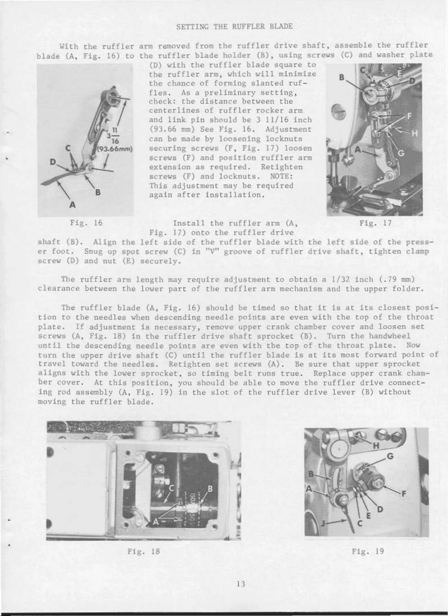
SETTING
THE
RUFFLF.R
BLADE
blade
With
(A,
A
the
Fig
ruffler
. 16)
arm removed from
to
the
ruffler
(D)
the
the
fles
check: the
ccnterlines
and
(93.66
can
securing
screws
extension
screws
This
aga
with
ruffler
chance
.
As
link
mm)
be made by
(F)
(F) and
adj
in
after
blade
the
pin
screws
ustment
ruffler
arm, which
of
forming
a
preliminary
distan
of
should
See
and
as
required.
inst
the
rufflcr
Fig. 16
loosening
position
locknuts.
ruffler
holder
blade
<'c
between t he
be 3 11/
(r,
may
allation
rig.
be
slanted
. Adjustment
drive
(8),
will mini
setti
rocker
ruffle
Retighten
required
using
square
ru
ng ,
arm
16
locknuts
17)
.
loosen
r arm
~OTE
shaft,
mize
f-
inch
:
screws
to
assemble
(C)
and washer
1
the
ruffler
plate
Fig.
shaft
er
screw
clearance
tion
plate.
screws
until
turn
travel
aligns
ber.
ing
moving t
(B).
foot.
(D) and
The
The
to
(A,
the
the
toward
with
cover
rod
16
Align
Snug
ru
ffler
between
ruf
the
If
adjustment
Fig
descending
upper
.
ass
embly (A,
he
ruffl
up
nut
fler
nee
dles
. 18)
drive
the
the lower
At
this
the
spot
(E)
ann
the
blade
needles
er
blade
Fig.
left
screw
securely
length
lower
(A,
when
in
needle
shaft
position
Fig
descend
is
necessary
the
.
sprocket
. 19)
.
Install
17)
side
(C)
may
part
Fig
ruffler
points
(C)
Retighten
, you
onto
of
in
.
require
of
. 16)
ing
unt
, so
in
the
the
the
"V"
the
should
needle
, remove
drive
are
i l
the
timing
should
slot
rufC!er
the
ruffler
groove
adjustment
ruffler
shaft
even
ruffler
set
be
ruffler
blade
of
arm mechanism and
be timed
points
upper
sprocket
with
screws
belt
of
runs
able
the
arm
crank
the
blade
(A)
to
ru
(A
drive
with
ruffler
to obtain
so
are
.
true
mo
ffl
even
top
ve
er
,
the
drive
th
at
chamber
(B) . Turn
of
is
at
Be
sure
.
the ruffler
dr
left
a
it
with
the
its
Replace
ive
side
shaft,
1/32
the
is
at
the
cover
the
throat
most
that
upper
lever
Fig. 17
of
tighten
inch
its
top
and
upper
dr
(B)
(.
upper fo
closest
of the
loosen
handwheel
plate
forward
crank
ive
without
the
79
sprocket
connect-
mm)
lde
.
point
pressclamp
throat
set
~ow
cham-
r.
posi-
of
•
•
.
...,
Fig.
18
lj
,
f
~
•
:&.-
Fig. 19
I 3
Page 3
If
you
ball
(40
nut
ward
D)
"xist
through
b
lnde
.
joints
mm)
(D)
or
After
in
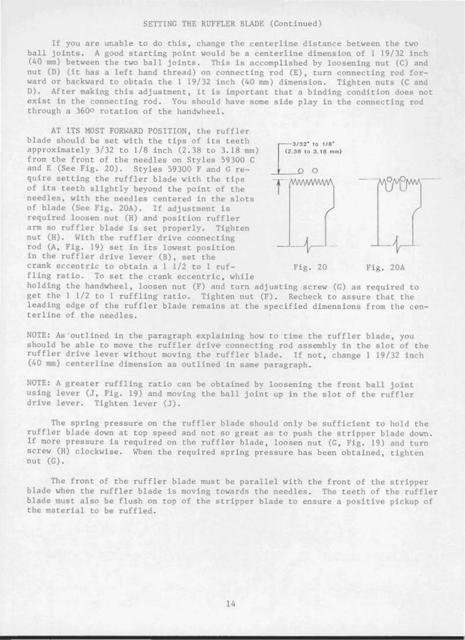
AT
should
between
(it
backward
the
a 3600
ITS
approximat
from
the
front
and E (See
q
uire
of
needles,
of
required
arm
nut
rod
in
crank
f
lin
hold
get
leadin
terline
setting
its
teeth
blade
so
ruffler
(H)
. With
(A,
the
ruffler
eccentric
g
ratio
ing
the
g edge
with
(See
loosen
Fig
the
I
of
are
u~able
. A good
the
has
a
left
to
making
this
connecting
rotation
HOST
be
ely
Fig
FORI<ARD
set
3/3
2
of
the
. 20) .
th" r u
slightly
th"
needles
Fig. 20A)
nut
blade
the
.
19)
set
drive
to
.
To
set the
handwheel, l
l/
2
to
1
of
the
the
n"edles
SETTING
to
starting
two
ball
hand
obtain
adjustment,
rod.
of
wi
th
to
1/8
needles
Sty
ffler
beyond
.
(H) and
is
set
ruffler
in
its
lever
ob
tai
n a I
oosen
ruffling
ruffler
.
THE
do
this,
point
joints
thread)
the
I
You
th"
POSI
handwheel.
TION,
the tips
inc
h (2 .
on
les
59300 F and G
blade
with
the
centered
If
adjustment
position
properly
drive
lowest
(B),
set
1/2
cra
nk
eccentric,
nut
ratio
blade
RUFFLER
change
would
.
on
19/32
it
should
the
of
its
38
to
Styles
the
point
in
This
is
the
be a centerline
connecting
inch
important
have
ru(fler
teeth
3
.18
59300 C
tips
of
slots
is
ruffler
.
Tighten
connecting
position
the
to
I
ruf-
while
(F) nnd
.
Tighten
remain s
at
lll..AOE
the
is
(40
mm)
re-
the
tu
rn
nut
the
(Conti
centerline
nued)
distance
accomplished
rod
mm)
some
(E),
dimension
that
side
a
play
Fig
adjusting
screw
(F) . Recheck
specified
between
dimension
by
loosening
turn
binding
connecting
.
Tighten
condition
in
the
. 20
(G)
to
assure
dimensi
ons
the
of
I 19/32
nut
rod
nuts
connecting
Fig. 20A
as
required
that
fro
m the
two
inch
(C) and
for-
(C
and
does
not
rod
to
the
cen-
NOTE: As"outlined
should
ruffler
(40
NOTE
using
driv"
rufflcr
If
more
screw
nut
blade
blade
the
be
able
drive
mm)
: A
centerlin"
greater
lever
lever
The
spring
blade
pressure
(H)
cl
(C) .
The
front
when
must
material
to
lever
(J,
.
Tighten
down
ockwise
of
the
ruffle
also
to
in
the
move
without
dimens
ruffling
Fig
. 19) and moving
paragraph
the
ruf
moving
ion
rati
lever
press
is
be
be
ure
at
top
required
.
When
the
ruffler
r
flush
ruffled
on
speed
the
blade
on
.
the
top
fle
as
o
(J)
on
blade
is
explaining
r
drive·
the
outlined
can
be
the
.
ruffler
and
the
not
rufflcr
requir
must
ed
connecting
ruffler
in
obtained
ball
blade
so
great as
spri
be
moving towards
of
the
stripper
how
to
blade
same
paragraph
by
loosening
joint
should
bl
ade,
ng
pressure
parallel
the
blade
ti
me
rod
.
up
assembly
If
in
only
to
push
loosen
has
with
needles
to
the
ruf(ler
in
not
, change I
.
the
the
slot
front
of
be sufficient
the
nut
been
the
. The
ensure
stripper
(G,
l'ig
obtained,
front
teeth
a
positive
blade
the
slot
19/32
ball
the
to
. 19) a
of
the
of
, you
of
inch
joint
ruffler
hold
blade
nd
Lighten
stripper
the
ruffler
pickup
the
the
down
turn
of
.
J 4
Page 4
LOOPER
FRAME
THROW
-OU
T
The
the
used
at
By
loopers
only
the
pulling
actuating
the
left,
frame
the
SURE
er
loopers
to
frame back
before
•
Although
sary
to
procedures
the
needle
looper
when
top
of
looper
pin
the
is
released
push
starting
make
will
lever
f rame throw -
easier
their
the
.
It
needles
stroke
throw-out
(A, Fig
looper
. 21)
holder
tilting
forward.
the
into
to
the
looper
po
siti
operate
machines
adjustments,
help
in
.
can
are
.
to
BE
hold-
on
.
are
the
installing
out
(Fig
. 21)
be
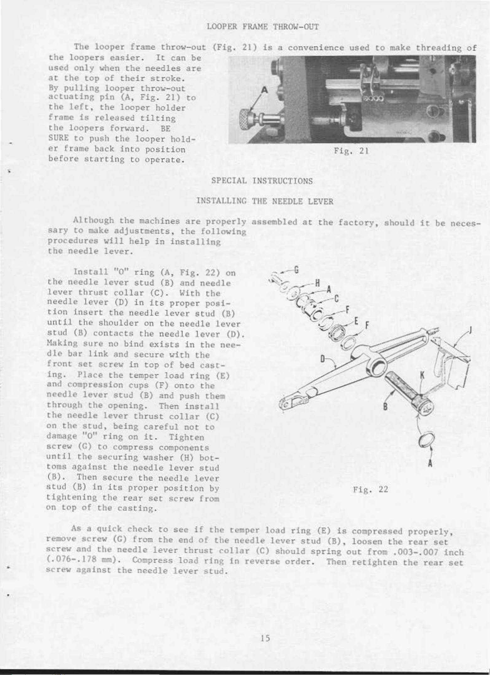
SPECIAL
INSTALLING
properly
following
is
a
convenience
INSTRUCT10NS
THE
assembled
NEEDLE
at
LEVER
the
used
Fig.
21
factory,
to
make
should
threading
it
be
neces-
of
Install
the
lever
needle
tion
until
stud
Haking
dll'
front
ing.
and
needle
through
the
on
damage
screw
until
toms
needle
thrust
lever
insert
the
(B)
sure
bar
link
set
Place
compression
lever
the
needle
the
stud,
"0"
(G)
the
ag~inst
(B) . Then
stud
(ll)
tightening
on
top
of
"0"
lever
col
(D)
the
ring
stud
lar
in
needle
sl:tOulder on
contacts
no
bind
and
screw
the
secure
in
temper
cups
stud
opening
lever
thrust
being
ring
to
on
compress components
securing
the
needle
secure
in
lts
the
the
proper
rear
casting
(A,
(B) and nee
(C) . With t
its
the
the
needle
exists
top
(F)
Fig
proper
lever
needle
with
of
bed
load
onto
. 22) on
he
posi-
stud
lev
er
in
the
the
cast-
ring
the
dle
lever
(E)
(B) and push them
. Then
careful
it
.
washer
the needle
position
set
install
collar
not
Tighten
(H)
lever
bot-
stud
lever
screw
from
(C)
to
by
.
(B)
(0).
nee-
Fig
. 22
As
a
quick
remove
screw
(.076-.178
•
screw
screw
and
the
mm)
against
check
(G) from
needle
.
Compress
the
needle
ro
see
the
lever
lever
if
end
thrust
load
the
of
ring
Stud
the
~ollar
.
temper
needle
(C)
in
reverse
load
lever
15
ring
stud
should
order
(E)
is
(B),
spring
. Then
compressed
loosen
out
from
the
retighten
properly,
rear
set
.003-.007
the
rear
inch
set
Page 5
To
hooks
proper
(B).
needle
portion
the
set
insure
into
the
position
For
proper
lever
falls
screws.
positive
supply
and
alignment,
stud
into
INSTALLING
hole
secured,
(B)
the
until
lubricating
oiling
(K)
loosen
the
of
of
the
proper
indented
THE
the
the
the
hole
NEEDLE
needle
needle
amount
needle
"UP"
(K)
in
LEVER
lever
lever
of
oil
lever
is
in
the
(Continued)
stud
stud
stud
the
needle
is
(B),
(B) .
fed
set
up
position
lever
the
bearing
When
to
the
screws
stud
oiler
located
needle
and
and
rotale
the
(B).
(J)
in
its
lever
stud
the
hook
Retighten
'fhis
of
various
actual
listing
required
Numbers
position
ordering
Component
ed
by
indenting
Example:
catalog
sections
position
of
the
in
the
in
of
thal
parls.
has
of
in
the
parts
particular
the
first
part
Always
parts
of
their
been
arranged
the
mechanism
nachine. On
with
their
view
column
in
the
use
sub
illustration.
the
- asse~blies
descriptions
ORDERING
ILLUSTRATIONS
to
simplify
are
the
part
being
are
part
page
numbers,
shown.
reference
number
which can
under
REPAIR
shown
opposite
Reference
listed
the
description
PARTS
ordering
so
that
repair
the
the
descriptions
numbers
only
numbers
in
the
be
furnished
parts.
parts
may
illustration
and
and
the
numbers
merely
should
second
for
of
the
column.
repairs
main
Exploded views
be
seen
will
:Ln
be found a
of
pieces
indicate
never
be
are
used
indicat-
sub-assembly
their
the
in
.
32 29133
p
33 77
34 22894 c
35 22894 L
It
will
listed.
ed,
no
the
so
the
In
those
specific
various
description
At
the
this
the
book.
part
be
noted
The
reason
complete sub-assembly
cases
usage
machines
and,
bock
This
number
where a
will
if
of
the
will
is
known
Take- up
Drive
Screw- - - - - - - - - - - - - - - - - - -
in
is
Set
Spot
the
that
Screw- - - - - -
Screw - - - - - - - - - - - - - -
above example
replacement
should
part
is
common
be mentioned
are
necessary,
not
book
the
will
same,
the
be
differences
facilitate locatine
.
Eccentric
that
of
be
to
in
the
the
found a
the
Assembly - - - - - - -
the
these
eccentric
parts
ordered.
all
the
description.
specific
will
usage
be
numerical
illustration
and
individually
machines
covered
However, when
will
shown
index
in
of
and
- - - - - 1
bearing
is
not
by
the
are
this
part
be mentioned
the
all
illustration.
the
parts
description
not
recommend-
catalog,
for
in
the
shown
when
in
only
1
1
1
IDENTU"iiNG
Where
some
of
tification
Part
HIPORTANT!
PART
IS
the
the
construction
smaller
letter
numbers
Qi
ORDERED.
pares
is
stamped
represent
ALL
ORDERS,
permits,
each
and on chose where
in
to
distinguish
the
same
part,
PLEASE
INCLUDE
PARTS
part
is
construction
the
regardless
PART
16
stamped
part
of
NA}IE
A,_D
with
does
from
similar
catalog
STYLE
its
not
in
OF
part
which
number.
permit,
ones.
they
MACHINE
an
FOR
On
iden-
appear.
WHICH
Page 6
USE
GENUINE
NEEDLES
AND
REPAIR
PARTS
Success
SPECIAl.
Needles
subsidiaries
approved
~iency
scientific
and
Genuine
parts
your
are
guarantee
Prices
warded
re~
ted
f.
o. b.
. A
in
the
and
and
durability
needles
stamped
of
ore
net
shippi
charge
operation
Repair
authorized
principles,
are
are
with
assured.
packaged
the
the· highest
ca
sh and su
ng
point
is
made
to
of
these
Parts
as
distributors.
and
are
with
Union
Special
quality
bject
.
Parcel
cover
postage
TORQUE
machines
furnished
They
made
labels
can
by
are
with
marked
trademark,
in
materials
TERNS
to
cha
Post
nge
shipments
and
wit
insurance
REQUIREI'!ENTS
be
secured
the
Union
designed
utmost
~~-
Special
according
precision.
U S Emblem. Each
and
ho
'.-lOrkmanship.
ut notice. All
are
insured
.
only
unless
wHh
genuine
Corporation,
to
the
~~ximum
Genuine
effi-
repair
trademark
shipments
are
otherwise
UNION
its
most
is
for
di
-
-
Torque (measured
distance
driver,
of
torque
All
unless
hand
as
The
by a
etc.
lever
Many
will
straps
otherwise
Lightly
screws
(in
of
tighten
and
as
req
eccentrics
not
ed. Al l
poss
uirin
in
inch-pounds)
inches
these
the
i bl e ,
g a
or
devices
part
to
should
other
unless
specific
is
a
feet)
are
the
nuts,
.
available,
correct
be
tightened
bolts,
otherwise
torque, will
rotating
This
is
amount
noted
force
(in
accomplished
which
to
when
and
no
19-21
screws, etc.,
.
be
indicated
pounds)
by a
set
wrench,
at
the
tighter.
inch-pound
should
on
be
the
applied
through
screw
proper
amount
(22-24cm/kg),
tightened
picture
plates
-
by
.
1 7
Page 7
10
j
11
t1
l\
~
...
/
40
.
,,
.,
~
\
18
Page 8
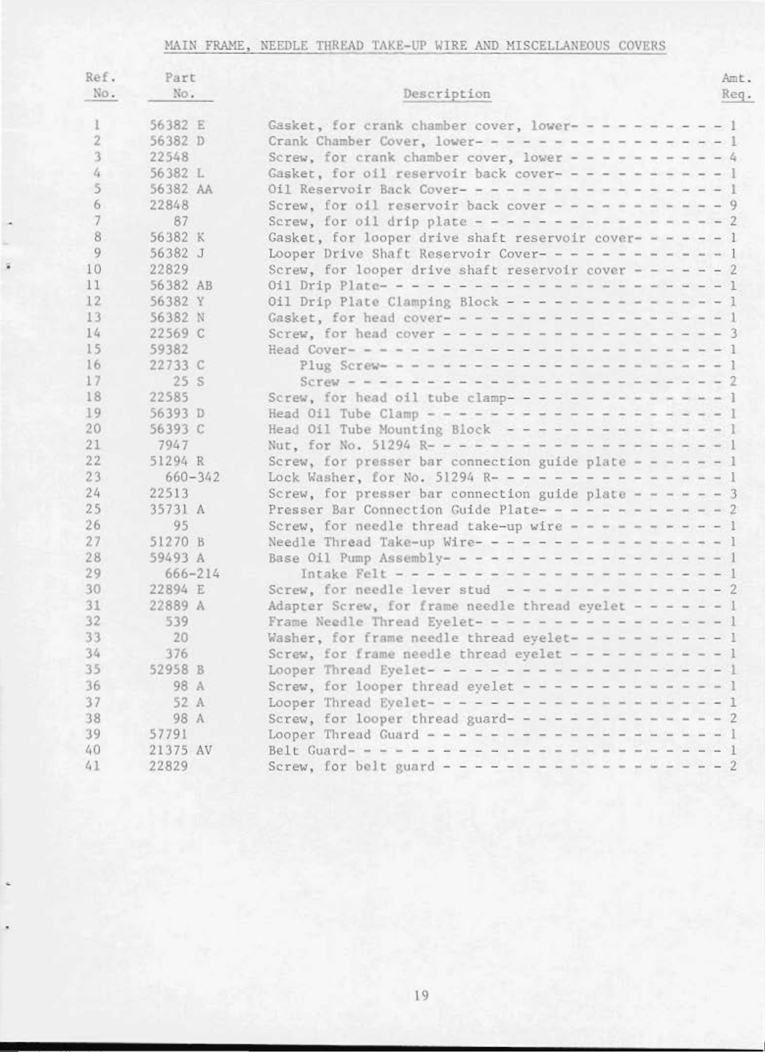
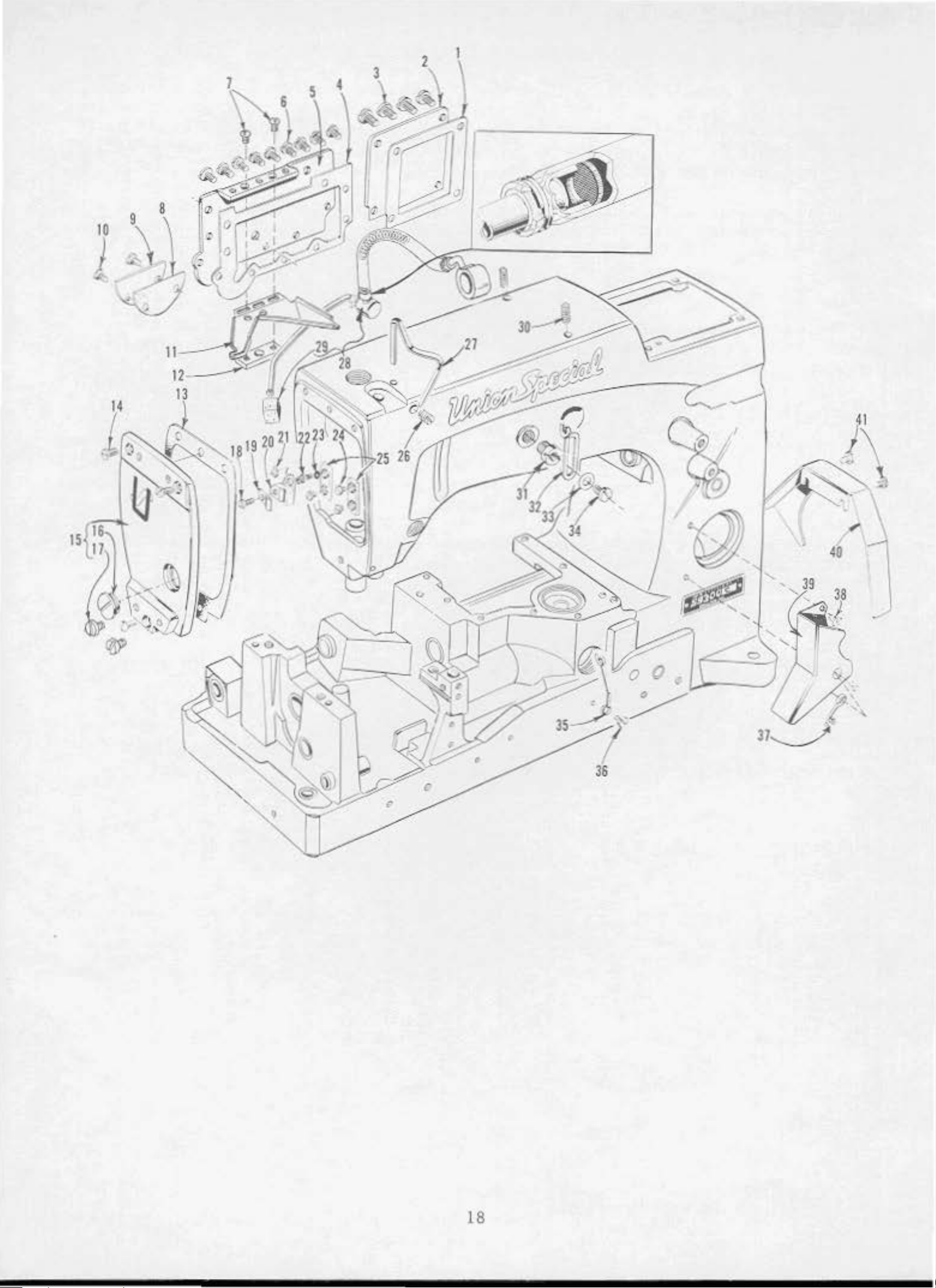
~lAIN
FRAME,
NEEDLE
THREAD
TAKE-UP
WIRE
AND
HISCELLANEOUS
COVERS
Ref.
No.
I
2
3
4
5
6
7
8
9
;
10
11
12
13
14
IS
16
17
18
19
20
21
22
23
24
25
26
27
28
29
30
31
32
33
34
35
36
37
38
39
40
41
Part
No.
56382 E
56382
D
22548
56382
56382
L
AA
22848
87
56382 K
56382 J
22829
56382
AB
56382 y
56382 N
22569 c
59382
22733
25
c
s
22585
56393 D
56393
c
7947
51294 R
660-342
22513
35731 A
95
51270
ll
59493 A
666-214
22894 E
22889 A
539
20
376
52958 B
98
A
52
A
98 A
57791
21375
AV
22829
Description
Gasket,
for
crank
chamber
Crank Chamber Cover,
Screw,
Gasket,
Oil
Screw,
Screw,
Gasket ,
Looper
Screw,
Oil
Oil
Gasket,
Screw,
Head
for
for
crank
oil
Reservoir
for
oil
for
oil
for
Drive
for
Drip
Drip
for
Cover-
Plug
looper
PlatePlate
for
head
head
- - - - - - - - - - - - - - - - - 1
Screw- - - - - - - - - - - - - - - - - - - - I
chamber
reservoir
Back
Cover-
reservoir
drtp
looper
Shaft
drive
Reservo
drive
- - - - - - - - - - - - - - - - - - - 1
Clamping Block - - - - - - - - - - l
cover-
cover
Screw - - - - - - - - - - - - - - - - 2
Screw,
Head
Head
Nut,
Screw,
Lock
Screw,
Presser
Screw,
Needle Thread
Base
Screw,
Adapter
for
Oil
Oil
for
Tube Clamp - - - - - - - - - - - 1
Tube Hounting Block - - - - - - - - I
No.
for
Washer,
for
Bar Connection Guide
for
Oil
Pump
Intake
for
Screw,
head
presser
presser
needle
oil
51294
for
No
Rbar
bar
thread
Take-up Wire- - - - - - - - - - - - l
Assembly- - - - - - - - 1
Felt
needle
- - - - - - - - - - - - - - - - - 1
lever
for
frame
Frame Needle Thread
Washer,
Screw,
Looper Thread
Screw,
Looper Thread
Screw,
Looper
Be
lt
Screw,
for
for
frame
frame
needle
needle
Eyelet
for
looper
thread
Eyelet-
for
looper
thread
Thread Guard - - - - - - - - - 1
Guard- - - - - - - - - - - - - - - - - - 1
for
belt
guard
lower-
cover,
cover,
- - - - - 1
back
lower-
lower
cover-
- - - I
- - - - - - - - 4
- - - - - - - - I
- - - - - - - - - - - - 1
plate
back
- - - - - - - - - - - - - - 2
shaft
ir
shaft
cover
reservoir
Cove
r-
reservoir
- - - - - - - 9
cover---
-
--
- - - - - - - - - - - I
cover
- - - - 2
- - - - - - - - - - - - - - - 1
- - - - - - - - - - 3
tube
clamp- - - - - - I
- - - - - - - - - - - - - - - - - - 1
connection
. 51294
connection
ta
stud
needle
Eyelet-
thread
thread
R-
- - - - - - - - - - - - - - 1
Plate
ke-
up
- - - - - - - - - - 2
- - - - - - - - - - - - - 1
guide
gu
ide
plale
plate
- - - - 1
- - - - - - 3
- - - - - - - - - - 2
wire
thread
eyelet-
eyelet
- - - - 1
eyelet
- - - - - - - I
- - - - 1
- - - - - - - - - - - - - - - 1
eyelet
- - - - - - - I
- - - - - - - - - - - - - - - - 1
guard
----
- - - - - - - - - - 2
---
-
--
- -
-- --
- - 2
Amt .
Rcq
1
1
.
19
Page 9
16
0
17
18
1S
32
20
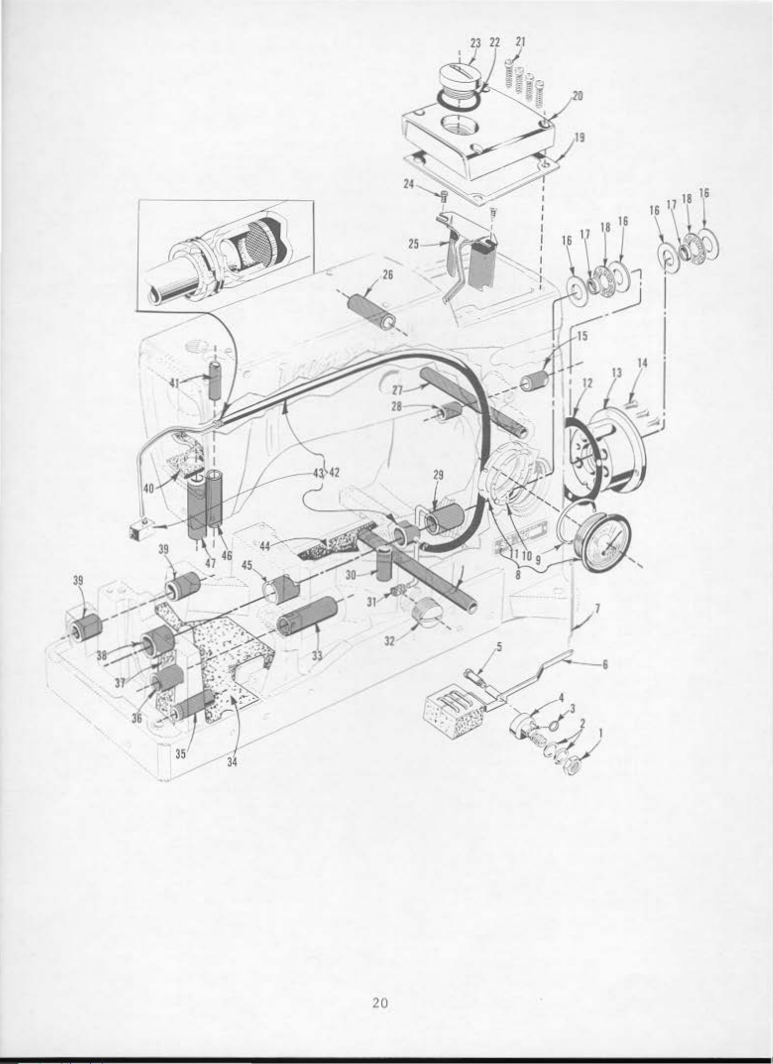
Page 10
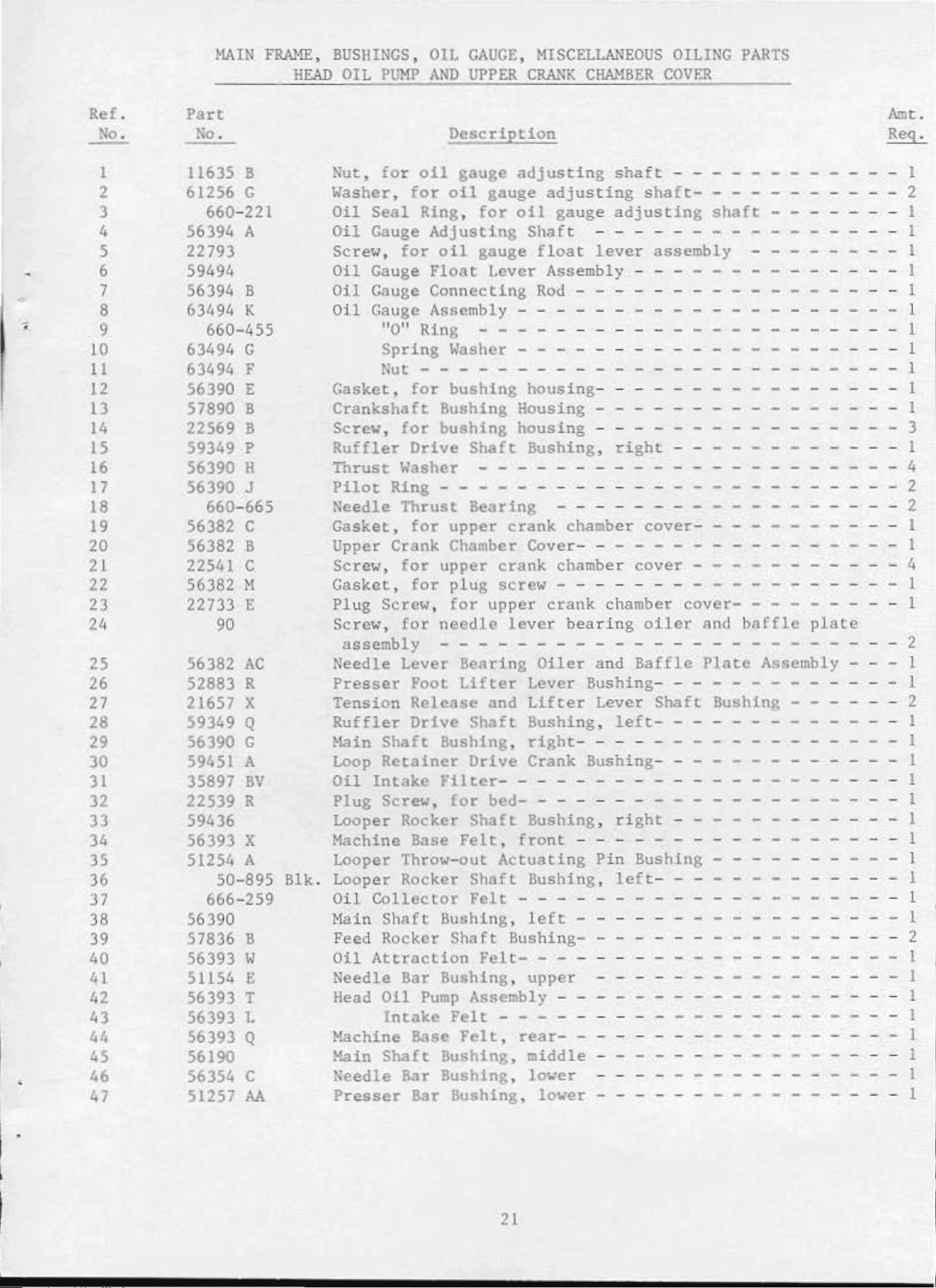
~lAIN
FRAHE,
BUSHINGS,
HEAD
OIL
PUMP
OIL
AND
GAUGE,
UPPER
CRANK
MISCELLANEOUS
CHAMBER
OILING
COVER
PARTS
•
•
Ref.
No.
I
2
3
4
5
6
7
8
9
10
11
12
13
14
15
16
17
18
19
20
21
22
23
24
25
26
27
28
29
30
31
32
33
34
35
36
37
38
39
40
41
42
43
44
45
46
47
Part
No
.
11635 B
61256
G
660-221
56394
A
22793
59494
56394
B
63494 K
660-455
63494
G
63494 F
56390 E
57890 B
22569 8
59349 p
56390 H
56390 J
660-665
56382
c
56382 B
22541
c
56382 H
22733 E
90
56382
AC
52883 R
21657 X
59349 Q
56390 G
59451 A
35897
BV
22539 R
59436
56393 X
51254 A
50-895
666-259
56390
57836 B
56393
w
51154 E
56393
1'
56393 L
56393 Q
56190
56354 c
51257 M
8lk
Description
Nut,
Washer,
Oil
Oil
Screw,
Oil
Oil
Oil
for
for
Seal
Gauge
for
Gauge
Gauge
oil
Ring,
gauge
oil
Adjusting
oil
Float
Connecting
Gauge Assembly - - - - - - - - - - - - - - - - 1
11011
Spring
Ring - - - - - - - - - - - - - - - - 1
Washer - - - - - - - - - - - - - - - - I
Nut - - - - - - - - - - - - - - - - - - - - - - - 1
Gasket ,
Crankshaft
Screw,
Ruffler
Thrust
Pilot
Needle
Gasket,
Uppe
r Crank Chamber Cover- - - - - - - - - - - - - - - I
Screw,
Gasket,
Plug
Screw,
assembly
Needle Lever
Presser
Tension
Ruffler
Main
Loop
Oil
Intake
Plug Screw,
Looper Rocker
Machine Base
for
bushing
Bushing Housing - - - - - - - - - - 1
for
bushing
Drive
Shaft
Washer - - - - - - - - - - - - - - - - - - 4
Ring - - - - - - - - - - - - - - - - - - - - 2
Thrust
for
for
for
Screw,
for
Bearing
upper
upper
plug
for
needle
- - - - - - - - - - - - - - - - - - - - - - 2
Beari
Foot
Lifter
Release
Drive
Shaft
Retainer
Shaft
Bushing,
Drive
Filter
for
Shaft
Felt,
Looper Throw-out
Looper Rocker
.
Oil
Main
Feed
Oil
Collector
Shaft
Rocker
Attraclion
Needle
Head
Oil
Intake
}~chine
}~in
Shaft
Bar Bushing, upper
Pump
Base
Shaft
Felt
Bushing,
Shaft
Assembly - -
Felt
Felt,
Bushing,
Needle Bar Bushing,
Presser
Bar Bushing, lower -
adjusting
gauge
for
gauge
adjusting
oil
gauge
Shaf
floa
t - - - - - - - - - - - - - - 1
t
Lever Assembl
Rod
- - - - - - - - - 1
housing
housing
Bushing,
shaft
adjusting
lever
- - - - - - - - - - 1
shaft-
- - - - - - - - - - 2
shaft
- - - I
assembly - - - - - - I
y - - - - - - - - - - - - - - I
-----
-
--
---
---
- - - - - - - - - - - - - - - - 3
right
- - - - - - - - - - - - 1
- - - - - - - - - - - - 2
crank
crank
chamber
chamber
cover
cover
--
---
- - - - - - - 4
screw - - - - - - - - - - - - - - - - 1
upper
lever bearing
ng
crank
Oiler
chamber
oiler
and
Baffle
cover-
and
Plate
- - - - 1
baffle
plate
Assembly - - - 1
Lever Bushing- - - - - - - 1
and
Lifter
Lever
Bushing ,
right
- - - - - - - - - - - - - - - 1
left-
Shaft
Bushing - - - - 2
- - - - - - - - - - 1
Crank Bushing- - - - - - - - - - - 1
- - - - - - - - - - - - - - - - - 1
bed-
Actuating
- - - - - - - -
Bushing ,
front
---
Bushing,
ri
Pi
n Bushing -
left
ght
- -
- -
-
- - - - - - - - - - - 1
- - - 1
- - - - - - - -
Bushing-
Felt-
left
- - - - - - - - - -
- - - - - - -
- - - -
- - - - - rear---
middle
lower
----
-
- - - - - - - - -
- - - I
Arnt.
Req
.
1
I
1
l
1
1
1
2
1
1
l
I
1
1
1
21
Page 11
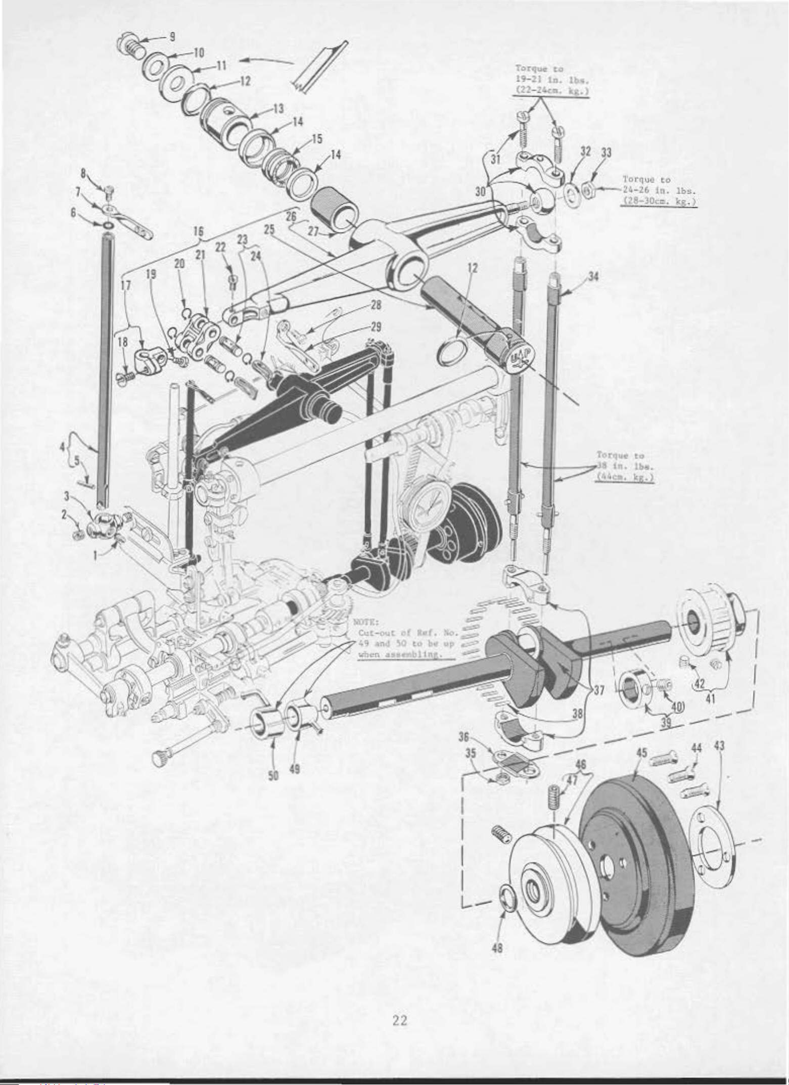
'Torqu~
19- 21
t.o
1a.
lb•
.
.
34
y, r
'"'
to
'"·
·
lbe.
kg
. 2
(4t,c~;
I
49
-
L..--
22
Page 12

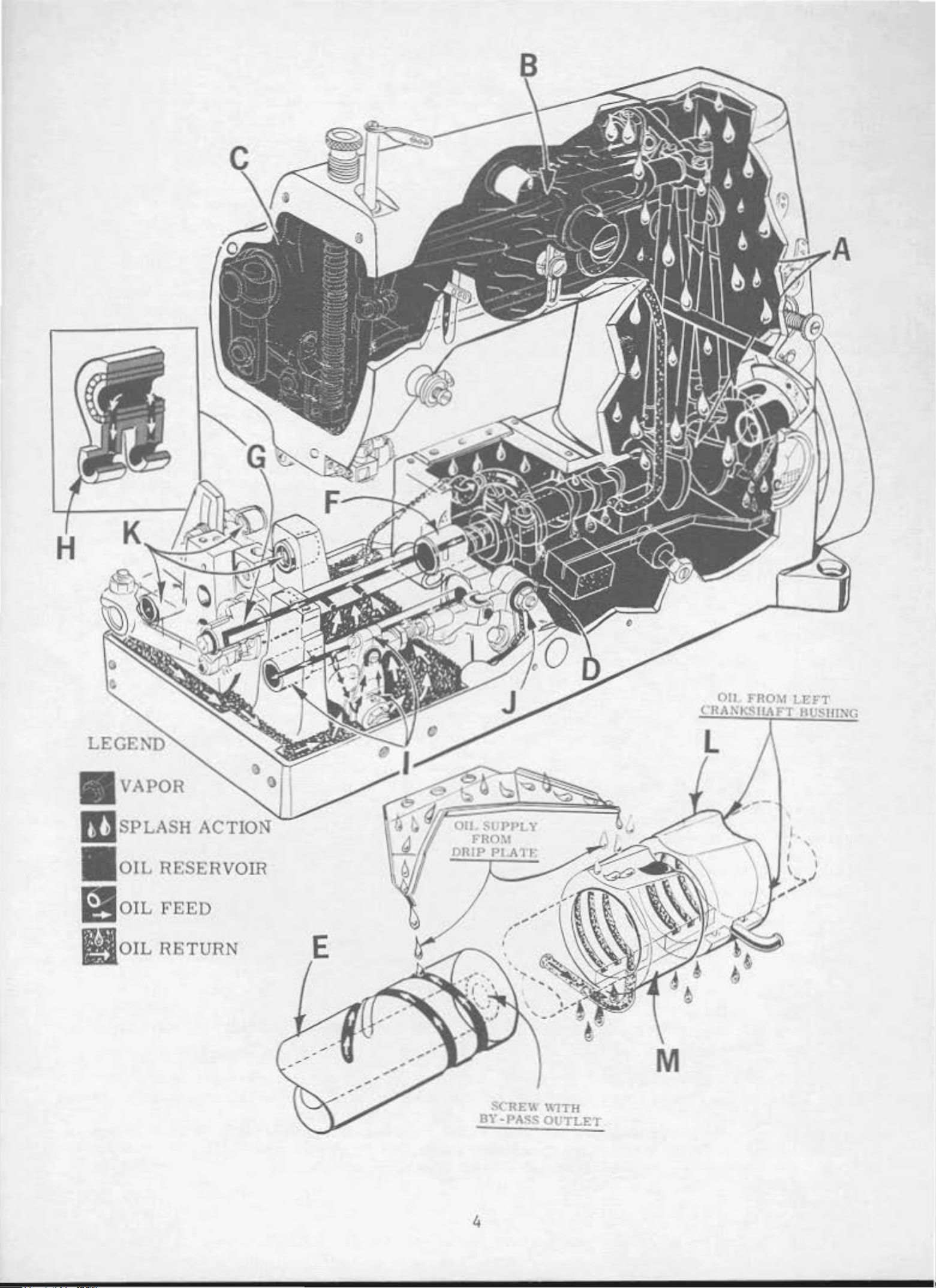
ADVANCED
FLATBED
LUBRICA
TIOK
SYSTEl\l
Figu
Lette
A.
B.
c.
ll.
E.
re
r
Bearing
or
Cl·ankshaft
and
crankshaft
Needle
Head
lever
area
ings).
Looper
lever
drive
bearings.
Opposing
end
of
mainshaft.
vents
shaft
oil
leakage
bE>aring.
Machine
drives,
bearings.
cross
(all
mechanisms
crank,
Helical
Area
upper
shaft
looper
grooves
Short
from
SUPPLY
ball
straps
bearing.
and
bear
drive
in
right
groove
pr
e-
right main-
SYSTEM
-
Method
Oil
ions
of
Lubrica
agitation
on
needle
as
rods.
Oil
supplied
trough
by
(51282
splash
i\llistas a result
Oil
agitation
(56343
E)
connecting
Oil
splash
drip
in
as a result
on
bottom
rod
plate;,
chamber
bon
a
result
lever
of
splash
.
which
.
of
connecting
AE)
in
which
column
in
ofs
of
looper
accumulates
extens-
is
area
column.
plash
er
drive
.
F .
G.
I-1.
I.
J.
Hight
Left
mains
mainshaft
tric bearings
Lower
mainshaft
Looper
rocker
per
Right
joint
ends
eccentrics.
cone,
shaft
rod ball
looper
.
haft
bearing.
bearing
lo
cated on
of
connecting
right
bearings,
joint
.
1·od
and
mainshaft
and
left
and
needle
all
eccen
rods
looper
left
be a ring
loo
.
of
-
Supply
grooves
shaft.
Oil
supplied
and
metered
trodu
ced
right
Amount
shaft
in
Oil
controlled
right
run-
supplies.
Supplied
shaft
yarn
Oil
to
which
as a metering
supplied
lubricating
by
into
mains
of
lubricant
end
of
out
from
from
in
right
from
felt
hollow
plugs.
center
haft
with
mainshaft
eccentric
hollow
contains
device.
from
plate
(56393 I<).
end
of shaft
bearing
in
by-pass
.
looper
4
strands
front
of
main
mainshaft
Oil
is
in-
in
the
area.
center
of
hole
bearing
rocker
of
base
felt
-
•
I<
.
Figure
Letter
L.
i\1!
.
Feed
rocker
Mach
Head
Base
rocker
shaft
ine
Area
shaft
and
bearings.
upp
er
RETURN
feed
SYSTEM
Self -lubrica
Method
Felt
pump
primed
of
pad
located
by
Return
in
bearing.
Felt
retur.n
and
pad
in
pump
primE>d
accumulates
chamber.
ted
head
oil
base
loca
by
splash
bearings.
collects
on
crankshaft
from
left
collects
ted
oil
drip
in
oil.
crankshaft
oil.
on
crankshaft
plate
looper
Return
and
Second
which
drive
5
Page 13

CRANKSHAFT,
NEEDLE
LEVER,
NEEDLE
8AR
AND
PULLEY
<
Ref.
No.
I
2
3
4
5
6
7
8
9
10
I I
I 2
13
14
15
16
17
18
19
20
21
22
23
24
25
26
27
28
29
30
31
32
Part
No
.
89
98
59318-16
59317-16
50
J- 16
27
- 435 Blk .
56458 A
22768
22586
R
51250 F
51250 D
660-625
56350
E
56350 F
660-614
29348
AF
51254 K
22562 A
22564
660- 215
56354 0
77
52336 A
W0
- 3
56350
D
56315 A
56350 G
22768
59358
A
29066 R
22559 G
51216
N
Amt.
Description
Spot
Screw,
1\eedle
Needle
Needle
Screw,
for
Holder,
Bar,
Stop
Pin
Bar
for
needle
needles-
marked
marked 11FB" - - - - - - - - - - - - - - - - 1
- - - - - - - - - - - - - - - - - - - 1
Eyelet
Needl e Bar Thread
Screw,
for
needle
holder
- - - - -
- - - 1
- - - - - - - - - - - "DD-16"
- - - - - - - - - - - I
Washer - - - - - - - - - - - - - - - - - I
Eyelet
bar
- - - - - - - - - - - - - - 1
thread
eyelet
- - - - - - I
Req
Screw - - - - - - - - - - - - - - - - - - - - - - - - - - - I
CasketHasher-
Oil
Seal
Needle
Thrust
Temper Load
Needle
- - - - - - - - - - - - - - - - - - - - I
- - - - - - - - - - - - - - - - - - - Ring - - - - - - - - - - - - - - - - -
Lever
\~asher
Thrust
Collar-
- - - - - - - - - - 1
- - - - - - - - - - - - - - - - - - - 2
Ring-
- - - - - - - - - - - - - - - - - 1
Lever Assembly - - - - - - - - - - - - -
Needle
~1r
Connection
- - - - - - - - - - -
Screw - - - - - - - - - - - - - -
Screw- - - - - -
Retaining
Needle Bar
Screw-
Link
Pin
Columb
Ring -
Link
- - - - -
- - - -
La
Yar n
(6
strands)
- 4
- - - 1
- - - - - - - - - - -
Needle Lever Stud - - - - - - - - - - - - - - - - - - 1
Needle
Screw,
Needle
for
Lever
Needle Lever
Lever - - - - - - - - - - - - - - - - - - - I
Bushing
needle
Thread
Connecting
- - - - - - - - - - - - - - - - - I
lever
Eyelet
thread
eyelet
- - - - - - - - - 1
- - - - - - - - - - - - - - - 1
Rod
Upper Ball
Joint
Assembly - - - 1
Screw- - - - - - - - - - - - - - - - - - - - - 2
Washer,
for
needle
lever
connecting
rod
upper
ball
joint
.
2
1
2
1
I
I
1
1
2
33
34
35
36
37
38
39
40
41
42
43
44
45
46
47
48
49
so
51216 p
56316
12934
A
56316 c
29476
51216 M
MD
57847
95
56334 K
59484 D
98
61321 L
22574
57821
56321
22894
:\
AB
660-202
assembly
Nut,
for
assembly
Needle
Nut,
for
Connecting
Crankshaft
Needle
Th
rust
ScrewDrive
Drive
Sprocket,
Sprocket,
Screw-
Retaining
Screw - - - - - - - - - - - - - - - - - - - - - 3
~andwheel
Pulley-
Screw-
"0"
Head
Base
Ring,
Oil
Oil
- - - - - - - - - - - - - - - - - - - - - - - - - l
needle
lever
connecting
rod
upper
ball
joint
- - - - - - - - - - - - - - - - - - - - - - - I
Lever
connecting
Connecting
Rod
rod gui
Rod
Guide-
- - - - - - - - - - - - - I
Assembly, . 910
- - - - - - - - - - - - - - 2
de
- - - - - - - - - - - I
inch
t hrow - - - - - - - - - - I
Bearing - - - - - - - - - - - - - -28
Collar
- - - - - - - - - - - - - - - - - - - - - I
- - - - - - - - - - - - - - - - - - - - - - 2
for
for
- - - - - - - - - - - - - - - - - - - - - - 2
Plate
Styles
Styles
59300 C, F 59300 E, G
-----
---
- I
-
---
- - - - - - - - - - - - - - 1
- - - - - - - - - - - - - - - - - - - - - - - I
- - - - - - - - - - - - - - - - - - - - - - - - I
- - - - - - - - - - - - - - - - - - 2
for
Pump
Pump
pulley-
Assembly
Assembly
- -
(See
(See
Ref .
Ref .
!':o. 42!':o. 28-
Page
Page
21)-
19)-
- - - - l
-
-
1
1
1
23
Page 14

6
s
,,
-
,.,
(
I o •
l·lioc~.
lll.s.
I<
.•
)
24
Page 15

Ref.
No.
Part
No
~lAIN
.
SHAFT
AN1)
FEED
Description
DRIVING PARTS
Amt
Req
.
.
=
<
1
2
3
4
5
6
7
8
9
10
11
12
13
14
15
16
17
18
19
20
21
22
23
24
25
26
27
28
29
30
31
32
33
34
35
36
37
38
39
40
41
42
43
44
45
46
47
48
56335 L
56335 D
98
56334
B
59235 A
22651
CD-4
660-438
41
391
59234
22651
CB-4
22901
22560
B
59234 c
59434 B
22713
20
14077
22900
57834
59305-
HA61
29476
22894
G
16
D
MK
AA
77
39543 N
59222
22891
B
56322 B
51236 A
61341 J
29476
MJ
55235 E
6042 A
55235 D
77
56336 B
56336 c
51054
666-149
269
21657
E
22525 A
56322 c
56336
22798
c
22543 A
660- 269 B
56336 D
-062
Feed Rocker
Feed Rocker
Shaft
Shaft
- - - - - - - - - - - - - - - - - 1
Collar-
- - - - - - - - - - - - - - - I
Screw - - - - - - - - - - - - - - - - - - - - - 2
Feed Bar
Shaft-
- - - - - - - - - - - - - - - - - - I
Feed Rocker - - - - - - - - - - - - - - - - - - - - - - 1
Screw - - - - - - - - - - - - - - - - - - - - - - - 2
Retaining
Washer,
Feed
Bar-
Ring,
for
feed
for
feed
rocker
rocker
shaft
-
shaft
---
-
-- --
- - - - - - - 1
-
---
- - - - - - - - - - - - - - - 1
l
Screw - - - - - - - - - - - - - - - - - - - l
Set
Screw - - - - - - - - - - - - - - - 1
Screw - - - - - - - - - - - - - - - - - - - 2
Feed Bar
Feed Bar
Tilting
Tilting
Extension
Extension
- - - - - - - - - - - - - 1
Pin
- - - - - - - - - I
Screw - - - - - - - - - - - - - - - - - - - 2
Washer- - - - - - - - - - - - - - - - - - - - - 1
Nuc
Feed
- - - - - - - - - - - - - - - - - - - - 1
Dog
Tilt
Eccentric
Screw - - - - - - - - - - - I
Bushing - - - - - - - - - - - - - - - - - - - - 2
Feed Dog- - - - - - - - - - - - - - - - - - - - - - I
Screw,
Feed
Lift
Set
for
feed dog - - - - - - - - - - - - I
Eccentric
Assembly- - - - - - - - - - - - 1
Screw - - - - - - - - - - - - - - - - - 1
Screw - - - - - - - - - - - - - - - - - - - I
Thrust
Main
Link
Washer,
Feed Rocker
Washer,
ShaftScrew - Casket-
Pin,
for
for
for
feed bar
-
---
-
------
- 2
- - - - - - - - - - - - - - 1
- - - 1
feed
feed
Arm
bar
- - - - - - - - - - - - - - -
bar
--- ---
and Feed Crank Link
---
Sub-assembly-
-
2
- - - I
Nut - -
Washer- - - - - - - - - - - - - - - - - - - - - - -
Locking
Stud-
- - - - - - - - - - - - - - - 1
1
Screw - - - - - - - - - - - - - - - - - - • - - - - I
Feed Crank Link Assembly - - - - - - - - - - - 1
Feed Crank Link
Feed Crank Link
Oil
Nut,
Washer,
Screw,
tlain
for
feed
for
for
Shaft
Feed Crank
Screw,
Stitch
Quad
for
Regulating
Ring,
Feed Crank
Pin
Wick- - - - - - - - - - - - - - - - - - 1
crank
feed
main
Head
Stud
feed
shaft
Plate
, marked
crank
stu
crank stud
Screw - - - - - - - - - - - - 1
for
Stud
feed
Insert
crank
Ferrule
- - - - - - - - 1
- - - - - - - - - - - - I
d-
head
- - - - - - - - - - plate-
- - - - - -
- - - - l
- - - 4
- - - "A"
stud-
- - - - - - - - - - - - I
- - - - - - - - - - 1
stud
- - - - - - - - - - - - - I
- - - - - - - - - - - - - - - - - I
I
1
I
1
1
25
Page 16

21
\ ,
41'
...
2
7 5
26
Page 17

TAKE-UP
~~D
LOOP
ER
DRIVE
PARTS
•
Ref.
No
.
1
2 59444
3
4 41358
5 59259 Looper Thread
6 59444 M
7
8
9 53678
10 54244
11 15489
12
13
14
15
16
17
18 59444
19 51242 L
20 54244 R Looper
21
22
23
24
25
26
27
28
29
30 18
31
32 29133
33
34
35
36 54195
37
38 29133
39
'•0
41
42
43 59444
44
45
46 55244
47 51236 A
48
49
so
51
52
53
54
55
Part
~o.
C0-67 E Cork
Looper Rocker
J87
54244
59444
41071
HS82
51225
54244
59444 L
39543
54285
59285-2-16
54208 A Looper,
54244
59444 G Looper
55244
51236 A
22894
22894 L
22768
22894 c
59451 R Looper
J Screw,
Wa
Screw,
c
p
N
J Looper Throw
B
G
w
H
R Washer,
J Looper
c
22
KH
97
A
Loop
Neoprene
1
.-lasher,
Screw,
Nut
Screw,
'.J'asher,
Looper
Collar,
Washe
Nu
Looper
Screw,
Screw,
c Looper
G Locking
20
Link Pin-
p
77
Tak
c
Coupling-
98 Screw -
~I
98
A
18
20 Washer-
Looper
Loope r T
c
Link
22585
57858 Looper
54223 A Looper
59445 A
66~215
6042 A Washer,
59344 Looper
39173 A Looper Frame
c Screw,
Looper
Retaining
Plug,
for
sher,
er
,
t,
Washer-
~ut
e-up Drive
Sc
Set
Spot
Screw
Set
Screw -
Nut
Locking
for
for
Throw-out
Washer,
for
for
for
r,
for
screw
for
for
Throw-out
for
for
Holder
for
Holder
looper
Holder,
marked
for
for
Holder
Holder
-
re
w - -
Screw - - - - - - - - - -
Screw-
Drive
Screw
Retainer
rav
-
Pin
- -
for
Thread
Thread
Thread
for
Holder
for
looper
looper
looper
looper holder
looper
looper
- -
-
looper
Shaft
screw
Eyelet
Fork
for
looper
-out
looper
looper
looper
looper
Stud-
Actuating
No
.
Fork
Frame
Frame
holder
marked
"CB"
~·ramc
Fr
ame
-
- -
- -
-
-
Eccentric
- - -
-
thread
No. J87
throw-out
th
throw-out
HS82
holder
holde
holder
Locking
holder
-
-
--
holder-
Th
Driving
- - -
-
- - - - - -
-
- - -
-
Descr
rocker
-
- - - - -
- - - - - - - - - - -
loope
row-out
Pressure
-
"AAu-
-
-
row-out
-- -
-
ietion
-- ------ --
eyelet
J
r
Pin-
-
-
fr
ame
f rame
r f rame
frame
frame
- - - - - - - - - -
screw-
-
- - - - -
- -
- - -
- - -
-
Assemb
- - - -
- -
- - - -
-
- - - - -
Eccentric
--
- - - -
-
- - - - -
-
Drive
- - - - -
el
Drive
- -
- - -
Stud-
- -
looper
Pull-off
Take-up - - - - - - -
Take-up
Ring-
looper
l'reme
Locking
-
-
-
thread
- - - - -
-
-
- -
Gea
- -
-
Assembly - - - - - - -
- - - - -
r-
- - - - - - - - - -
Link-
-
-
- - - - - - - - - -
- - - - - - - - - - -
- - -
pull-off
Eye
let
Drive
- - - - - - -
holder
Shiel
Pin Spring
frame
d-
shaft-
- - - -
-
-
- - -
-
- -
- -
actuating
throw-out
actuating
- - -
actuating
-
Pin
- - - - -
-
l ocking
locking
Spring
lock
locking
- - -
locking
-
-
--
--
- - - -
Spring
Arm
pin
actuating
pin-
- -
- -
pin
-
- - -
--
pin
- -
pi
n -
- - -
pin-
pi n
- - -
pin
- - - -
-
- - -
--
-
-
- - - - - -
- - -
-
-
- -
- 1
- - -
-
-
- - -
- - - - - - - -
- -
- - -
ly
- -
- -
- - -
-
-- -
-
-
- - -
- - -
--
- - - -
- - - - -
- - - - -
- - - - - -
- - - - - - - -
- - - -
-
- - - - - - - -
- - - -
Link
locking
- - - - - - -
- - - -
- - - - - - - -
- - -
- - -
-
- - -
- -
- -
-- - -
- -
- - -
eyelet-
-
- -
--
- -
- - - - - -
- -
pin
- -
- - -
--
--
- - - - -
---
-
-
- -
--
- -
pin
- -
-
--
- -
-
- 1
-
- -
- - - - -
-
-
- - -
- - - -
-
- 1
-- -
- -
- I
-
-
- - - -
- - - -
- -
--
- - -
-
- - -
-
-
-
- - -
-
- - - -
- -
-
-
- - -
- - -
-
- - -
- -
- - -
----
-
-
- 1
- -
-
- - -
- - -
- -
-
-
-
-
- -
- - -
-
--
- - -
--
--
- -
- -
---
--
- - -
--
-
- -
-- -
-
-
--
- - - -
--
- -
- -
- - -
- - -
--
- -
--
---
--
-
-
- - - 1
-
- - -
-
- - -
--
-
- -
- - -
- 1
- -
- -
- -
- - - 1
-
-
- - - 1
- - 1
-
---
- - -
-
- - -
- - -
-
- - - -
- - - 1
- - - 2
----
- - 1
A.mt
Reg.
1
1
- 2
2
1
1
1
1
1
1
1
1
1
1
1
1
1
1
2
-
2
-
1
1
1
-
1
-
1
1
1
1
1
6
- 1
1
- 2
2
1
1
l
1
l
1
1
1
.
27
Page 18

4
3
30
2
2
24 23
28
Page 19

CLOTH
PLATE,
SWINGING
BRACKET
AND
LOOP RETAINER
DRIVING
PARTS
Ref.
No. No.
I 59401 8
Part
2 22839 c
3 22574
4
* 5
* 6
* 7
8 28577
9
10
11 59364
12
13
14
15
16
17
18
19
20
21
22
23
24
25
26
27
28
29
30
31
32
33
34
35
36
37
38 59451
39
40
41
42
43
23425
23443
9937
22504 A
22574 D
59451 F
59451
59451
59482 A
59451 c
666-206
660-337
56382 H
59451 u
22580 E
59493
59451 w
531
59451
627
59324-16
59480 c
59380
51280 J
22839
22524
22585 A
59311
12986 B
54264 c
54264 B
80
25
c
v
B
B
T
88
90
v
18
A
87
0
87 u
Am
Cloth
Screw,
Screw,
Screw,
Screw,
Place
for
for
for
for
Washer Plate
Hemmi
l/6
Washer,
Nut , fo r
Pi
Folder
Sc
Washer,
Loop
Loop
Oil
ng
Attachment,
in
ch (
vot
Screw,
Hounting Swinging
rew,
for
Retainer
Retainer
Reservoir
for
pivot
for
Fulcrum and
Oil
Oil
Gasket
Retainer
Wick,
Seal
for,
for
Ring - - - - - - - - - - - - - - - - - - - 1
Driven
Description
- - - - - - - - - - - - - - - - l
cloth
cloth
cloth
hemming
,
l.
59
pivot
for
loop
loop
Slide
oil
plateplate-
plate
- - - - - - - - - - - - - - - - - 2
attachme
for
hemming
lower, 1
mm)
capacity-
screw
screw-
- - - - - - - - - - - - - 2
folder
retainer
retainer
Holder and
Driving
Top
Cover - - - - - - - - - - - - - - 1
Arm
Block - - - - - - - - - - - - - - - - 1
fulcrum and
reservoir
Gear-
- - - - - - - - - - - - - - - 1
- - - - - - - - - - - - - - - - - - 2
- - - - - - - - - - - - - - - - - - 1
nt - - - - - - - - - - - - - 2
attachment
/4
inch
- - - - - - - - 1
(6.
35
mm)
hem
turned
- - - - - - - - - - - - - 1
-
---
mounting s
llracket
driving
driving
Driving
- - - - - winging
bracket
--
- - - - - l
- - - - - - - - - - l
arm- - - - - - - - 1
arm - - - - - - - 1
Arm-
- - - - - - - - - I
Crank - - - - - - - - 1
slide
top
block
cover
- - - - - - - 1
-
--
- - - - - 1
Req
up
1
Screw - - - - - - - - - - - - - - - - - - - 2
St
op
Collar
and
Oil
Slinge
r - - - - - - - - - - - - 1
Screw - - - - - - - - - - - - - - - - - - - 2
Screw ,
Retainer
Screw,
Retainer
Nut - - - - - - - - - - - - - - - - - - - - - - - - 1
for
Arm
for
Arm
retainer
Support,
retainer
Support,
arm su
pport
, upper- - - - - - - - - - - 2
upper - - - - - - - - - - - - - - 1
arm
support,
lower- - - - - - - - - 1
lower - - - - - - - - - - - - - - 1
Screw - - - - - - - - - - - - - - - 1
Throat
Screw,
Throat
Throat
Screw,
Screw,
Retainer
Screw,
Lo
op
S
crew,
Scr
ew, for
Latch
Spring
Plate-
for
Plate
Plate
Dowel
Pin
for
for
Holder
for
Retainer,
for
Spring,
Clip,
- - - - - - - - - - - - - - - - - - - - - 1
throat
plate
- - - - - - - - - - - - 3
Support Shim - - - - - - - - - - - 1
Support-
- - - - - - - - - - - - - 1
- - - - - - - - - - - - - - - 2
throat
oil
oil
loop
lalch
for
for
plate
reservoir
Plate
reservo
marked
- - - - - - - - - - - - - - - - - 1
i r
"BY
retainer-
spring
folder
swinging
support
top
to
p cover- - - - - - - - - 3
- - - - - - - - - - 2
cove
r-
- - - - - - - - - - 8
"- - - - - - - - - - - 1
- - - - - - - - - - - 2
- - - - - - - - - - - - - - 1
mounting
bracket,
swinging
(not
shown)- - - - - - - 1
bracket-
I
t.
.
*
Available
•
as
an
extra
send
and
charge
item
29
.
Page 20

2 A
12
~
• •
-
30
Page 21

Ref.
No.
Part
No
STRIPPER
.
BLAD
E,
FOLD
ERS,
BRACKETS
AND
Description
RUFFLER
PARTS
A:nt
Rcq
.
.
I
2
2A
3
4
5
6
7
8
9
10
*1 1
12
13
14
*15
*
16
*l
7
18
19
20
21
22
23
24
25
26
27
28
29
30
31
32
33
34
35
36
37
38
39
40
41
42
43
44
45
45A
59382
s
25
22733 c
59340 c
22882
59340
B
22596
I I 85 L
59340 A
12934
A
22704
23442
B
604
27-527
59340
59303
87
u
2 7-527
22504
59348 A
22798 A
29476
PA
59348
59349
F
605
51236 A
14077
22566 A
59349 D
667 D-16
59349 K
9660 B
98
59349
22
76/1
E
B
12934 A
22517
22704
59347
93
59347
43443
77
A
Q
Q
22704
59348 8
59346
59346 A
Blk
Bl
k.
Head
Strip
Screw,
folder
Stripper
bracket-
Screw, f
Washer,
Stripp
Nut,
Screw,
Hemming
Screw,
.
Washer,
Stripper
Ruffle
Screw, for
T
Screw,
Ru
~ut,
Shoulder
Ruffler
Dowel
SpacerCollar,
Cover-
Screw - - - - - - - - - - - - - - - - - - -
Plug
per
for
bracket
- - -
ScrewBlade
stripper
Blade
- - - - - - - - - - - - - -
Holder
Brac
blade
ket,
upper-
holder
bracket,
- - - - -
upper
- - - - - - - - - - - - - - - -
Holder B
racket,
lower
and
folder
- - - - - - - - - - - - - - - - -
or
er
for
turned
(2. 38
Washer,
ilting
f f
le
Ruffler
Ruffler
Link
for
Pin
strip
for
Bl
No.
ade
No. 22596-
for
hemmlng
Attachment,
down, 1/16
for
stripper
for
No
Blade-
Edge
mm)
Guide,
capacity
for
for
ti
Lever
for
Arm
tilti
Extension
Blade
Rocker
Screw,
Pinscrew
Screw,
Shaft
- - - - - - - - - - - - - - - 1
per
22596
Holder
blade
holder
---
- - - - - - - - - - 2
- -
--
- - - - 4
- - - - - - - - - - - I
- - - - - - - - - - - - - - - - 2
attac
uppe
inch
blade
hment - - - - - - - - - - - - - 2
r,
(1
1/4
.59
inch
mm)
(6. 35
capacity-
mm)
hem
- - - - - - 1
- - - - - - - - - - - - - 2
. 604 - - - - - - - - - - - - - - - - 2
- - - - - - - - - - - - - - 1
for
set
on
ruffles
3/32
inch
- - - - - - - - - - - -
ruffle
No
. 87 U - - - - - 2
ltin
g
- - - - - - - - ng
Holder
for
edge gu
le
ver
lever-
And
Blade
- -
ide
- - -
- - - - Holder
--
Arm Extensionruffle
r
rocker
- - - -
- - - - - - - - I
- - - - - - - - - - 1
- - - - 1
-
- - - - - - - - - I
arm
extension
- - - - - - - - - - - - - - - 1
~o
.
93
- - - - - - - - - - - - - - - 2
for
Bracket,
ruffler
left
shaft
bracket,
left
- - - - - - - - - - 1
- for
ruffler
rock
shaft
-
Screw -
Ruffler
Spot
Locknul - - - - - - - - - - - - - - - - - -
Rocker
A~n,
left
- - - - - - - - -
Screw- - - - - - - - - - - - - - - - -
Screw - - - - - - - - - - - - - - - - - -
Screw,
Rufflcr
Sc
rew,
Ruffler
Nut,
Screw,
Screw,
Ruffler
Ruffler
Ruffler
for
for
for
for
for
rufflcr
Blade
ru(fler
Slade
ruffler
adjusting
rufflcr
Blade
Slade,
Blade,
blade
tension
Tension Plate
blade
Tension
blade
ten
Plate
tension
ruffler
blade-
Support
for
for
- - - - - - - - - - - - - - Styles
Styles
plate
holder
- - - - - - - - sion
Holder
blade
plate
holder
- - - - - - - - -
adjusting
screw-
tension-
- - - - 1
- - - - - - - - - - - 2
59300
59300 F, G- -
C,
E- - - - - - - -
----
- - - 1
2
1
I
and
2
I
1
- 2 Screw,
I
- - - 1
I
---
- - - 1
- - - 1
- - - - 1
- - - I
- - - I
- - - 1
- 1
1
- 2
I
- - - - - 2
1
-
---
- - 1
I
1
1
* Order
~s
on
extra
send and char
ge
item
.
31
Page 22

1
18
17
',
24
~
~
'
;;;; \
\
23
32
Page 23

INSTRUCTIONS
FOR
MECHANICS
CAUTIO:>!
ervoir
oil
ounces
the
Fahrenheit
No
. 175 .
and
is
to
should
zone,
cans
must
gauge
(340.2
various
Use a
check
the
be added when
marked
No.
Oil
be
(8),
parts.
straight
in
Fill
oi.l
black
"LOW".
28604
has
filled
before
gr.)
the
level
main
main
line,
R.
been
.
drained
to
the
beginning
Run
Full
mineral
reservo
at
machine
speed
reservoir
gauge
located
need] e is
The recommended
proper
oil
i r
(B) .
LUSR I CA
from
to
slowly
operation
of
.
at
to
to
the
level
operate.
REC0}1}!ENOF.D
a Snybol t
This
plug
Oil
the
the
main
for
is
screw
is
right
black
oil
TI
0!'1
reservoir
at
plug
The
several
can
at
is
then
011..
viscosity
cqui
in
maximum
of
line,
available
screw
capacity
minutes
be
expected
valent
upper
"OPERATE"
to
crank
safe
located
in
before
(A,
of
of
90
Union Spec
operating
zone,
to
16
shipment,
Fig
.
the
to
distribute
without
to
chamber
marked
the
fluid
so
the
I)
as
indicated
reservoir
d~mage.
125
seconds
in l Sp('cification
cover
level
"FULL"
left
ounce
of
is
the
(A,
when
"OP~:RATE"
(453. 6 gr.)
oil
at
Hg
.
res-
on
12
to
1000
. 1)
needle
Oil
CAUTION!
It
is
an
extended
and
further
distribute
and
change
2000
drained
(C,
the
cover.
lubricated,
drop
ing
throw-out
looper
in
directly
hand
For
lint
the
operating
from main
Fig.
machine,
located
The machine
of
oil
rod,
retainer
the
oili
It
is
important
recommended
period
oil
oiling
oil
machines
deposits
oil.
I)
the
pin,
ng
to
hours,
lorated
or
by removing
at
and no
~t
both
ruffler
looper
holde
diagram
be
lubricated
the
An
is
needle
will
the
in
nt
reservoir
the
vario
operation
reasonable
oil
or
below
back
almost
oiling
ends
rock
holder
r and dr
(See Fi
that
that
be
us
change
once
the
of
entirely
other
of
shaft
these
a new
as
bar
required.
by removing
the
the
link
parts
check
intervals
is
a
year.
cloth
lo-....cr
machine.
than
adjustable
brackets,
frame
iving
g.
2)
machines
mnchinc,
follows:
and
.
the
recommended
plate
crank
automatically
an
locking
nrm
are
not
or
one
Remove
the
Run
oil
.
Oil
plug
occasional
as
required
needle
machine
for
If
every
may
screw
at
front
chamber
connect
the
indicated
looper
pin,
dir
dirty
be
-
and
.
be
over
that
the
bar
slowly
t
,
~
of
filled.
has
head
.
Replace
for
been
cover,
several
out
of
clean
head
.-..,-.£
,
__
-
__
service
out
cover
minutes
,
A
lint
as
to
~
for
no
daily
A
be made,
operating
Oil
and
frequent
main
(C,
front
hole
littl~
which
pumped
reservoir
Fig.
and
to
oili
I)
of
the
plug
gasket
check
see
level,
has
gone
back
ngs
located
machine
screw
cement,
before
that
as
into
unnecessary
may
the
outlined
through
the
be
drained
below
.
dry,
and
the
oil
main
After
paint
level
in
the
.
the
draining
re-assemble
morning
the
machine
reservoir,
Excessive
by removing
cloth
hole
is
first
plate
and
start
at
oil,
screw.
a
safe
paragraph
is
filtered
making
oil
plug
at
wipe
screw
6
should
too
in
the
screw
the
the
with
a
.
Fig.
I
Page 24

RUFFLER
HECHANISM
AND
COVER
Ref.
No.
I 59349 A
2
3
4
5 55235 E
6
Part
No.
59382
25
59349
6042 A
7 55235 D
8 59349
9 22852 A
10
I I
I 2
13
14
15
16
17
18
19
20
59349 c
667
18
20
59349 J
63439
59336 A
59349
9660 B
98
56334 c
59484
21
98
22651
22
23
24
25
26
27
28
29
30
31
32
33
34
35
5633L,
594
84
22795
59336
660-219
43242 p
59348 c
15037
59349 H
36253 J
59349
52776 v
53678 N
22804
35766
A
s
c
N
D-8
AD
F.
CB-4
H
I'
A
L
BA
p
Ruffler
Ruffler
Scr
ew,
Ruffler
Nut
\,
Blade Rock
Drive Cover - - - - - - - - - - - - - - - - - - I
for
Drive
- - - - - - - - - - - - - - - - - - - - - - 1
1
asher
Locking
Thrust
Screw,
R
uffl
Dowel
Nut,
Hasher,
for
er
Shaft
Pin,
for
ruffler
Washer, for
Ruffler
Drive Lever
Ferrule
Ruffler
Ruffler
Collar,
Feed Crank Stud - - - - - - - - - - - - - - - - I
Blade
for
Screw - - - - - - - - - - - - - - - - - - - - - - - 2
Driven
Driven
Sprocket,
Sprocket,
Screw,
Screw,
T
im
ing
Timing
Ruffler
Ruffler
Roll
Nut,
thread
Ruffler
Kut,
thread
Ruffler
Belt
Belt, for
Adjusting
Drive
Pin,
for
ruffler
- - - - - - - - - - - - - - - - - - - - - - - - - - 1
Shaft
for
ruffler
- - - - - - - - - - - - - - - - - - - - - - - - 1
Drive
Ferrule
Link
Release
Washe
Screw,
Nut , f
Retaining
Lever - - - - - - - - - - - - - - - - - - -
r,
for release
for
or
lin
Amt.
ruffler
Lever,
Description
Shaft-
drive
right
- - - - - - - - - - - - - 1
cover-
- - - - - - - - - - - - - - - - - 1
- - - - - - - - - - - - 2
Req
- - - - - - - - - - - - - - - - - - - - - J
Stud-
rufflcr
Bracket,
for
ruffler
- - - - - - - - - - - - - - - - - - - I
for
ruffler
ruffler
shaft
feed
feed
Link,
bracket,
right-
shaft
crank
crank
rear-
dr
ive
leve
right
r,
right
--
- -
-
---
---
- - - - - - - - - I
bracket
stud
- - - - - - - - - - 1
stud
,
right
----
- - - - - - I
- - - - - - - - - - - - I
-
-
--
--
1
2
2
- - - - - - - - - - - - - - - - - - - - 1
Drive
ruffler
for
for
,
No
No
for
Shaft
blade
for
for
Styles
Styles
. 56334
- - - - - - - - - - - - - 1
drive
shaft
- - - - - - - - - - - 2
59300 C, F- - - - - 1
59300 E, C- - - - - - - l
G-
- - - - - - - - - - - - 2
. 59484 E- - - - - - - - - - - - - 2
Styles
Styles
59300 C, F- - - - - - - 1
59300 E, G-
----
-
--
- - - - - l
Screw - - - - - - - - - - - - - - - - I
for
Shaft
rufflcr
Drive
Lever
Head- - - - - - - - - - - - - - - - - - l
drive
shaft
drive
Connecting
shaft
drive
Link,
shaft
connecting
Rod
connecting
front
- - - - - - - - - - - - 1
head- - - - - - - - - 1
rod,
left
hand
- - - - - - - - - - rod,
right
hnnd
l
- - - - - - - - - - - - - - - - 1
Screw- - - - - - - - - - - - - -
release
k
retnlnlng
lever
lever-
- - - l
screw
I
I
1
1
.
33
Page 25

34
Page 26

Tl!READ
TE:<SICN,
LIFTER
LEVER
AND
PRESSER
FOOT
PARTS
Ref.
No.
1
2
3
4
5
6
7
8
9
10
11
12
13
14
15
16
17
18
19
20
21
22
23
24
25
26
27
28
29
30
31
32
33
33A
34
35
36
37
38
39
40
41
42
43
44
45
46
47
48
49
50
51
52
53
54
55
56
Part
No.
21657
AL
21657 y
22596
402
51283 H
660-207
39552 c
53783 N
22537
56383
AB
52889 A
51256 c
56383
AA
56383 A
402
51257 M
21695 M
21695 z
21695 L
22729
531
22758
c
59492 A
22557 G
56383 D
43266
51491
c
52992 A
51292 D
21657
Al'l-5
39592 z
39592
51292
51292
AK
F-5
F-2
56392 F
109
56392 E
51292 A
53688
59320-16
59330 A
22840 A
51430 F
53530
91
22738 G
59330-16
22799
ll
59320 A-16
59330 8
22840 A
51430 r
53530
91
22738 G
59330 C-16
22799 B
Tension
Tension
Screw
Screw - - - - - - - - - - - - - - - - - - I
Lifter
Oi l
Lever-
Seal
Washer,
Lifter
Lever
Screw - - - - - - - - - - - - - - - - - - - - - - 1
Lifter
Lever
Presser
Presser
Lifter
Lifter
Screw,
Lever
Lever
for
Presser
Collar,
Finger
Guard- - - - - - - - - - - - - - - - - - - 1
Washer,
Screw,
Screw,
Screw,
for
for
for
Auxiliary
Screw,
for
Spring,
Nut ,
Thread
for
Lead-in
Tension
Tension
Tension
Tension
Tension
Tension
Tension
Tension
Tension
Tension
Tension
Presser
Pr
esser
Cloth
Sec Screw - - - - - - - - - - - - - - - - - - - - - - l
Locknut - - - - - - - - - - - - - 1
Shank, marked
Screw - - - - - - - - - - - - - - - - - - - - - - - - 2
Bottom- - - - - - - - - - - - - - - - - - - - - - 1
Hinge Screw - - - - - - - - - - - - - - - - - - - - - 1
Presser
Cloth
Set
Locknut - - - - - - - - - - - - - 1
Shank,
Screw - - - - - - - - - - - - - - - - - - - - - - 2
Presser
Screw - - - - - - - - - - - - - - - - - - - - 1
Amt.
Description
Release
Release
and
and
Lifter
Lifter
Lever
Lever
ShaftShaft
- - - - - I
Connection
- - - - I
Reg.
- - - - - - - - - - - - - - - - - - - - I
- - - - - - - - - - - - - - - - I
Ring,
for
Bar
Bar
presser
Bar
!or
for
presser
Tension
for
tension
for
lifter
lifter
lever
Connection
Connecting
Spring
Spring-
Bell
Link
Regulato
- - - - - - - - - - - - - - - 1
Crank - - - - - - - - - - - - - 1
- - - - - - - - - - - - - - - - 1
bar
Connection
finger
finger
finger
lifter
guardguard-
guard
bar
lever
Post
lifter
lifter
lever
lever
post
lever
- - - - - - - - - - - - - 1
- - - - - - - - - - - - - - - I
- - - - - - - - - - - - - - - 1
Rod
- - - - - - - - - - - - - 1
r and
connection
and
Guide- - - - - - - - - - - I
Presser
and
guide
Bar Bushing- l
- - - - - 1
- - - - - - - - - - - - 1
- - - - - - - - - - - - - - I
- - - - - - - - - - - - - I
connection
link-
Support
bell crank
bell crank
- - - - - - - - - - - - - - 2
and
guide
- - - - - 1
- - - - - - - - - - - - I
- - - - - - - - - - - - 1
- - - - - - - - 1
- - - - - - - 1
Guide- - - - - - - - - - - - - - - 4
Post
Thread
Disc
Nut
Spring
Spring,
Spring,
Spring
Disc-
PostPost
Bar - - - - - - - - - - - - - - - - - - - 1
Foot
Clamp
Foot
Support-
Eyelet
Separator
- - - - - - - - - - - - - - - 4
Ferrule-
needle-
looper-
Shield
- - - - - - - - - - - - - - - - - - 1
- - - - - - - - - - - - - - - - 4
- - - - - - - - - - - - - - - - 1
- - - - - - - - - - - - - - - 4
- - - - - - - - - - - - - 2
- - - - - - - - - - - - - - - 2
- - - - - - - - - - - - - - - - - - 4
- - - - - - - - - - - - - - - - - - - - 8
- - - - - - - - - - - - - - - - - - - - - - 4
Ferrule-
Assembly,
Shield-
- - - - - - - - - - - - - - - - 4
for
Styles
59300 C, £- - - - - - - 1
- - - - - - - - - - - - - - - - 1
"U"
- - - - - - - - - - - - - - - - 1
Screw - - - - - - - - - - - - - 1
Assembly,
Shield-
for
Styles
59300 F,
G-
- - - - 1
- - - - - - - - - - - - - - - - 1
Screw - - - - - - - - - - - - - - - - - - 1
=rked
''U" - - - - - - - - - - 1
Clamp Screw - - - - - - - - - - - - - - - - - - - 1
Foot Bottom - - - - - - - - - - - - - - - 1
35
Page 27

16
A
17
21
22
6
.....
3
I
~
36
Page 28

THREAD
STA~D
PARTS
A~D
ACCESSOR
IES
Ref.
No.
Part
No.
1 21101 H-4
2 21114
3
4 22651
5
6
21114 A
21114 T
22651
S- 4
CD-4
CD-4
7 22810
8
9 652-16
10
11
12
21114
21104
21114 D- 4
22651
u
ll
co-s
13 21104 B-24
14
15
16
17
21114 H-4
22651
CD-4
21104 v
21114 w
18 258 A
19
20
21114
652-16
21 51295 A
22
23
24
25
26
51295
660-240
21388
421
21201
28604
ll
D-34
R
660..457
Amt.
Req
Thread
Lead
Thread
Lead
Description
Stand
Eyelet
Screw - - - - - - - - - - - - - - - 1
Eyelet
Assembly - - - - -- - - - - - - - 1
- - - - - - - - - - - - 1
Stand
Base - - - - - - - - - - - - - 1
Socket
Ball
- - - - - - - - 1
Screw - - - - - - - - - - - - - - - - - - - - - 2
Screw - - - - - - - - - - - - - - - - - - - 1
Lead
Washer- - - - - - - - - - - - - - - - - - - -
Nut - - - - - - - - - - - - - - - - - - - - - - 1
Spool
Eyelet
Seat
Ball
Spli
Support
t Sock
et
- - - 2
- - - 1
- - - - - - - - - - - 1
Screw - - - - - - - - - - - - - 2
Thread
Eyelet
Stand
Rod- - - - - - - - - - - - 1
Support-
- - - - - - - - - - - - - - - - - - 1
Screw - - - - - - - - - - - - - - - 1
Pad,
Spool
Nuc - - - - - - - - - - - - - - - - - - - - 8
Spool
Washer- -
Isolator
Isolator-
for
thread
Pin
Seat
cone- - - - - - - - - - - - 4
- - - - - - - - - - - - - - - 4
Disc
- - - - - - - - - - - - 4
- - - - - - - - - - - - - 4
- - - - - - - - - - - - - - - - - - - - - - 1
- - - - - - - - - - - - - - - - - 3
Thread Tweezers - - - - - - - - - - - - - - 1
Wrench,
Tread
Screw
over-all
Can
of
Dust
single
le
Chain,
driver,
7-11/16
Oil,
Cover
end,
34
9/64
3/8
inches
inch
inches
Spec. 175, 1
(not
shown)- - - - - - - - - - - - - - - 1
inch
(863.60
(3
. 58
(194.
pint
(9.
mm)
26
(not
53
mm)
mm)
rou
long
nd
mrn)--
sho~1)
opening-
- - - - - 1
blade,
length
-- --
- - - 1
1
1
.
37
Page 29

NUMERl
CAL
lSDEX
OF
PARTS
Part
So.
l:G-3
.........
18
...............
20
...............
22
KH
............
25
c
.............
25
s
.............
27-435
27-527
50-895
50 J-16
52
HA61
C067 E
77. ' .. '.'
77
80
.... ' •.
HS82
•...
87
..............
87 u
J81 J
88
•..............
89 ..... ' .........
90
....
91. ... . . .
93 ........•..
95
....
97
98
. ..........
98
81k ..•..•
8lk ... .
Sl k ••••
..........
A . .
....
0
.........
....
Q
....
.••.••••
.............
..........
0
••••••••••
. .
A .... . . •
A
•••
•.•..•..••
l 09 . . . .... . 0 •
258
A
.......
269
. . . .
........
376
.. ....
402
.... ' .. ' .......
421 1)-34
531.
~39
.....
604
..............
60~
...............
627
652-16
660-202
660-207
660-215
660-219
660-221
660-240
660-269
660-337 ••.
660-342
660-438
660-455
660-457
660-614
660-625
660-665
666-149
666-206
666-214
666-259
667
667
1185 L ..•..•
6042 A ....•••.
..........
......
0
A
.....
............
..•..••...
....
. .•..... .
P
• ....•...•. 21
•....
B ....
•.
...
.•...
....•.
•.....
...........
.......••.•
...........
...........
.......
......
D-8
.•.......
0-16
.•..•..•
.
....
.
...
• • .
. .... • . 19
.. ..
.........
' .
....
..
..
. .
...
..
' • .... '.29
•••
...
........
.
...
....•
....
......
....
••
• 0 •
......
...
...
. .
....
...
..
. . .
•••••••••
........
.....
.........
..•..
' . .•.. '
' ' ' .
. . 35
..
.... . .
.....
. . . 29
..
...
......
. ...• 37
. .
...
. .
..
'
.• ' .21
..
. .
. .
.... 31
. .
•. 25,27,33
Page
No
.
23
27,29,33
19,25,27
33
27
29
19,31,33
. 23
31
21
23
25
27
23 ,25, 27
31
27
.
19,29
29,31
27
29
23
21.29
35
31
19 ,23
27
23,25
31
19
,27
, 33
35
37
25
19
35
37
29.35
19
. 31
31
29
37
. 23
23,27
33
)7
25
19
. 25
21
23
23
21
25
29
19
33
)1
Part
No.
79'7
...•......
9660
9937
11635
12934 A
12986 B .•..•......
14077 .......
15017 A •
15489 B . .
21101
21104
21104
21104 v .
21114 ...
21114
21114
21114
21114
21114
21114
21114
21201.
21375
21388
21657
21657
21657
21657
21657
21695 L ...
21695
21695
22504 .......
22504
22513
22517
22524
22525
22537
22539 R
22541 c
22543 A
22548
22557
22559
22560
8
............
...........•...
! .............
••••••••••
••
• •
....
11-4
......
B-24 ...
11
•• •
•••
.....•.
. .
......
A .••.
0-4 .•..•..•.
H-4
...........
S-4
. .
T
•••••••••••••
u
.............
w
.............
...•..........
AV
............
. .
.....
E
•••••••••••••
X
•••••••
Y • •
•••••••
AL
............
AM-5
. .... .
.. ..
M .....•..•
z ...
.......
A
............
•.•..••..•.••.•
•..•..•
...............
A
.•.....•.....
............
......
..........
.............
.. ' ..... ' .. ' ..
c
...........
c
.............
8
.•..•..•....
22562 A . . . .•..•.. ,
22564
22566
22569 B ..
22569
22574
22574 1), , ' ..........
22:>80
22585
22585 A .. , ..
22585
22586 R .............
22596
22651 CB-4
22651 C0-4
22651
2270/._'
22713
22729
22731
. 0 0 •
••••••
A ....
.....
c ..
'''
..
0 •••••••
P.
•• ' ••••• ' ••
. .......•..
c
.............
...............
..........
.•........
co-s
..........
. . ' . .... . ' ..•
.. ' ......
..•...
c ..
.........
.
.... 19
.....
•• ••••••
.....
.
....
.......
•••••••
. .. . . 37
..
•••
••.•• . 37
.......
....
•..•
••••••
• . • • 35
....
. .
....
...
•..•.
..
• .
.•..
.
......
• •
.........
.
....• 21
..
'' ....
• ••••
.. '.19
, ,
......
.
.....
0 • ••••
•
.
...
..
...
.
••
•••
Page
~o.
.
31,33
29
21
••
23,31
..
29
..
25.31
33
. . 27
37
37
37
. .
)7
. • 37
37
. . 37
37
JI
37
37
19
31
25
21
35
35
35
. 35
35
. 31
. 29
19
31
29
25
35
21
..
21
25
'19
..
35
23
.
25
..
23
• 2'\
31
19
23.29
29
• •
29
29
27
23
31.35
25,33
25,37
37
31
25
35
..
19,31
Part
No.
22733 E ..............
22738
227S8 C ....
22764 8 . .
22768
22793
22795
22798
22798
22799
22804
22810
22829
22839
22839
22840
22848
22852
22882
22889
22891
22894
22894 E
22894
22894
22894
22900 ... ' .....
22901.
23425
23442
23443
285 77' '
28604
29066
29133
29133
29348
29476
294
29476
29476
35731 A
35766
35897
36251
39173
39543
39543
39552
39592
39592
41071 c . .
41358
41391
43242 P ..............
43266 ...
43443
51054
51154 [ ...........•..
51216
51216
51216 P ..............
51225
51236 A ..............
51242
51250 D ..............
c
..............
..........
........
...............
................
. .
.............
A ••.••.
•.••..••
c .........
B ... . .
. .
...
..
' .
.....
.. ' .. ' .. ' .. ' ..
c
..............
A
•.•..•........
......
A
..........
................
A
..............
B
..............
c
..............
........
1..
AA
AB
..... ' .....
v . .
B
..........
6 .
.. ' ........
R ...
R
...........
!1
..............
r
............
AF
!-1l)
76
)!J
~~-062
PA
..............
BA
BV
J
•..•.....••.•
A
..............
N .
R
..............
.•.....•.
0 0 •••••••
.•..•..•.
.
.....
..........
••• ' ••••••••.
.............
.............
.. '·····
..........
...........
.............
.............
.............
.........
...........
... , .........
••• , ..... , ...
...
......•..•
c .. ' .. ······' .. 35
z ......
AK
. . , , ,
........•..•.
.......
......•......
Q
..............
•..•............
~--·
x
..............
u
............
L.
...........
........
,,,,
........
....
.•....•..•.
....
.....
' . . 37
.... . 19
,
......
..
. ' .
....
· ' .. 29
....
....
....
. .
Page
No.
21
35
35
31
.
23,27
21
. 33
31
25
35
••
33
' .
?.9
29
35
J9
...
33
31
19
2:>
27
19
27
25
23
..
25
25
31
..
'
29
'
..
29
37
..
. 23
27
..
21
23
23
25
25
..
31
19
33
21
.
33
27
25
27
35
35
21
... 27
.•.
25
33
35
31
25
21
23
23
23
. . 27
25 .27
..
27
23
,31
38
Page 30

NUMERICAL
INDEX
OF
PARTS
-
-·
-
P-'rt
No.
51250
51254 A
51254 K
51256
51257
51257
51270 R
51280
51283
51292
51292 o
51292
51292
51294 R
51295 A ........
51295
51430 f
51491
52336
52776 v .
52883 R
52889 A
52958
52992
53530 ...
53678
53688
53783
54195
54208 A
54223
54244
Sl12M1
54244 H
54244
542Mo
54264
54285
55235
55235
55244 G . .
56190
56315 A
56316
56316 c
56321 N
56322
56322 c .
56334 s .
56334 c
56334
56331•
56335
56335
56336
56336
56336
56336
56350
56350
56350 F
56350 G
56354 c .
56354 D
56382 B . . .
56382 c
F .....• .•...•..
.......
..............
c
.. ............
~1.
.
.....
AA ......
..............
J
..............
H .
....
. ••......
A
..............
...........
F-2 ....•.......
F-5 .....
....
...
s
..........
......
c ............
A
......
.....
•.••.••..
••..•.••
s
......
A
••..•••••••
...
..•..•....
•
......
.............
X
......
.....
.
.......
.......
A . .............
c
..............
C .
.... ,.,
......
J
...
......
R
..............
c .
...
..........
c ..............
o .
............
E .
....
..
..
••••
................ 21
.....
......
•
.•..•
..............
............
B
..............
...........
........
........
H •
....
K ••••••••••••••
o ....
L
.....
8 .......•. .... . 25
c .
D ......
D ..............
E
..•
...
....
....
......
....
.
..........
.........
....
.....
..
.............
..
...........
.....
......
..
.....
.
.....
....
...
..
.....
..
..
...
..
..
. .
..
....
....
....
..
....
....
....
...
. .
...
.••.
.•
........
.
•.
•.....
•..•
...
.
.......
..
.. ....
. . 27,33
..
....
..
....
.. , ..
.....
.....
•.....
. .
.....
..
..
.....
....
..
•.•...••.
.•.•.
........
. •
..
..
. • 25
......
..
...
......
......
......
......
Page
No
23
21
23
35
.
35
21
19
29
35
3)
. 35
35
35
19
37
37
35
35
23
. 33
21
35
19
35
35
. 35
35
. 27
27
27
2i
. 27
27
27
27
29
27
.
25,33
25,33
27
23
23
23
23
25
25
25
33
33
23
25
. 25
25
25
23
23
23
23
21
. 23
21
21
.... .
. . . 33
...
..
..
. .
.....
. .
...
... 29
.
...
....
..
....
.
...
.
.. ..
.
...
...
....
....
.
.....
Page
No.
31
31
31
. . 31
31
33
33
. 33
. . 31
31
31
. 33
.
33
33
..
31
..
33
33
21
..
21
23
29
19,31
..
33
29
25
21
. 27
27
..
2 7
27
..
27
..
27
27
27
21
29
.
29
29
29
27
29
..
29
29
..
29
.. 29
29
23
33
33
. 35
29
19
21
21
23
25
33
21
21
21
Part
No
.
.
56382 D .
56382
56382
56382K .......
56382
56382
56382 N
56382 y
56382
56382
56382
56383
56383
56383
56383
56390
56390 E
56390 c .
56390 H
56390
56392
56392 F ... .
56393 c
56393
56393
56393 Q
56393 T
56393
56393 x .....
56394
56394
56458 A •
57791
57821
57834
57836
57847
57858
57890 8
59222 ... .
59234 .........
59234
59235 A
59259
59285-2-16
59303
59305-16
59311
59317-16 ............. 23
59318
59320-16 .....
59320
59324-
59330-16 .....
59330
59330
59330 C-
59336
59336
59340 .
59340 A .
59340 B
59340
59344 .....
59346
59346 A
....
• ....
H
..............
.)
.........
.•... . . 19
l.
.............
M
.......
.......
....
AA
.............
AB .....
AC
.....
A
.............
..
..
..... .....
.. ..
....
D . . .....•... ..
AA
.•..•
AB
. ••.•••••.•.•
.........
.......
..
....
J ..............
E
........
.......
D .
.. .....
L
...
......
•.••.•••
• : . .
.
.......
..........
.....
...
•.
. ....
••.•...•
......
..
. .
..........
1
... 1 ••••••••••••
.........
A
......
B
........
...
...
..
. .......•
G
.........
8
..............
.......
..
. .... .....
......
c
..............
.........
..........
................
...
..........
-1 6 .
A-16 ...........
16
.......•...
A
......
B ......
16
.........
A
........
....
.. ··•··•·· ...
..
c
.....•........
.......
..............
........
•.•.
. · ·•·· ·
. .
.....
.
.......
......
...
......
. .
....
..........
. .
...
........
.
....
.....
.......
..
....
. . . • . . •
..........
. . .......
.
. .. •..• 23
......
...
•
• .
....
..
...
.....
.....
....
....
...
..
....
.....
....
....
....
....
.....
....
•..
...
....
....
..
.
....
.
...
....
......
.....
.....
.....
.. ..
.....
...
Page
. 35
. 35
..
• •
. . 23
..
. . 25
...
. 27
. .
. 35
..
...
..
No.
19
29
19
19
21
l9
19
I9
19
21
]5
3)
21
21
21
21
21
35
35
19
19
21
21
21
21
21
21
21
19
25
21
23
27
21
25
25
25
27
31
25
29
23
35
29
35
35
35
35
33
33
31
31
31
31
. 27
31
31
Part
No.
59347 . .
59347 A .
59348
59348
59348
59348
59349
59349
59349 c
59349
5931•9
59349 F
59349
59349
59349 J
59349
59349 1.
59349
59349 P
59349
59358 A .
59364 . ....
59380
59382 . .
59382 A
59401 8
59434
59436 .... ....
59444
59444
59444
59M•4 J
59444
59444
59444
59445
59451 A
591o51
59451 c
59451 D .
59451 F
59451 R
59451
59451
59451
59451
59480 c ..
59482
59484
59484 E
59484 F
59492 A
59493
59493
591•94
61256 G . .
61321
61341 J
631•39
63494 F
63494
63494 K
....
.....
.............
................
A .
....
s . .
.. ..
c
..............
.....
A
....
........
..........
.............
D
........
E
..............
....
..... .....
c
......
H .....
......
!(.
....
....
.
N
.......
.....
Q •.
......
.....
......
.............
.....
......
....
.. ..
B
....
..
....
A
..............
G
...........
..............
L
....
........
~1.
........
P ...
.. ...•.....
A
....
..........
B .
.............
...........
....
..............
.....
T
..............
u
............
v ......
II
............
..........
A
..............
o ..............
..........
....
.......
. . .
.............
A
....
............
........ .
L ..........
....
AD
....
........
c
......
..............
.. ...•.
........
.
..
.....
......
..
......
..
...
...
..
..
.
........
....
........
.. .......
•..•..
......
..........
........
.........
. . ........
•..•.....
.... .....
........
......
.
.....
.....
..........
.....
........
39
Page 31

OTL
GAUGE
The
voir
.
Should
followed
I .
2.
3.
'•
5.
6.
oil
:
}lake
·
Place
Remove
Remove
gauge
an
to
drai
sure
Fill
main
press
Loosen
the
to
left
the
is
set
adjustoent
the
machine
the
n
oil
oil reservoir
from
all
lower
crank
reser
shaft
bushing
locknut
or
right
left
of
at
the
becooe
upright
oil
the
is
reservoir
drained
chamber
voir
to
(D,
(E) on
the
until
"OPERATE"
factory
n~cessary,
on
plug
to
a
level
screw
.
from main
cover, loca
a
level
even
Flg. 1).
calibrating
the
gauge
zone,
marked
show t
however ,
table
(C, F
reservoir
ted
with
screw
needle
"Lm.J
he
proper
or
ig.
at
the
rests
11
•
the
bench
I )
the
botto
(F),
on
oil
following
.
and
tip
.
back
m
and
the
of
contour
turn
black
level
in
the
steps
machine
forward
the machine .
of
the
the
screw
line,
rese
should
knee
to
located
rbe
7.
8.
Fig
the>
needles are
angles
threaded
front.
Tighten
cover
Add
of
.
oil
"OPERATE"
. 2 shows
to
the
from
direction
right
locknut
so
that
the
insert
to
(E) and
gauge
zone,
marked
replace
needle
"FULL".
THRr:ADINC
manner Jn which
ed
in
of
left
the
line
.
n<'edlc
of
Also,
feed,
note
plug
rests
INSTRU
this
holder
the
that
screw
on
the
CTIONS
machine
with
spot
the
(C)
and
black line,
i s
thre
the
or
scarf
looper
aded .
eye,;
is
lower
locntcd
Please
in
a
plane
to
the
threaded
crank
left
from back
chamber
to
the
note
at
and
,
right
are
right
that
to
•
•
7
Page 32

FILL
MAIN
RESERVOIR
HERE.
THREADING
AND
OILING
FOR CORRECT
OIL
LEVEL
NEEDLE
SHOULD
OPERATE POSITION.
CAUTION
FILL
ALL
OIL RESERVOIRS
BEFORE STARTING .
MACHINE HAS
BEEN
BEFORE SHIPPING.
DIAGRAI'I FOR
CLASS
59300
OF
GAUGE
BE IN
DRAINED
Fig
. 2
\ihile
marked
BRICATION".
points
needles
to
the
from
"OPERATE". Por
indicated
Thread
direction
right
machine
arc
to
lt
should
by
machine
inserted
of
left
.
is
in
operation
further
be
noted
the arr
in
accordance
in
line-of-feed,
Also note
the
ows
needle
the
lubricating
that
on
that
an
the
with
holder
the
the
nbove
spot
n~~dle
instructions
occasional
the
with
looper
of
the
drop
diagram
threading
the
or
scarf
is
threaded
8
oil
refer
of
.
diagram
eyes
to
the
gauge
to
oil
above .
in
a
plane
left,
from back
should
paragraph
should
at
and
be
in
on "LU-
be
added
~ote
right
are
to
that
threaded
front.
the
angles
band
at
the
the
Page 33

SETTiNG
LOOPERS
AND
ALIGNIKC
NEEDLE
BAR
Insert
permit,
should
Fig
nnd
the
the
ening
frame
quired
in
made
the
loopers
rear
making
with
with
be
at
. J
point
(Fig
the
driving
hexagon
and
this
both
retighten
loopers
their
right
(A,
points
angles
(A,
tion
the
the
as
needles,
Retighten
holder
tween
of
loopers
are
at
th
.
3)
.
This
nut
arm. :·love
adjust~ent
loopers,
Fig
.
toward
(900),
Fig.
looper
loopers
left
possible
eir
(0
nut
4).
side
.003
frame (C)
the
are
farthest
can
,
Fig
the
(D)
.
in
order
3)
in
looper
th~
co
operator
the
Loosen
holder
so
when moving
of
the
without
inch
screw
(B)
so
centerline
l/8
inch
pojnt
be
accomplished
.
4)
in
the
looper
.
Looper
NOTE:
holder
The
to
maintain
holders
centerline
screw
that
forward,
needles
picking
( . 076
.
Set
the
(3
of
.
di
the
18
of
looper
gauge
1/8
. The
(B)
the
at
mm)
the
stance
needles
mm)
travel
by
frame
No.
inch
proper
(B)
as
right
of
and
posi-
point
passes
as
close
the
clearance
loope
be
r
-
when
to
loos-
holder
(C)
towards
21225-l/8
(3
. 18
mm)
needle
the
of
far
side
do~~
of
mainshaft.
.
the
can
be
looper
bar
as
their
the
looper
Tighten
Fig.
front
used
advantageously
gauge
alignment
shanks
4
or
rear
setting
.
blades
screws
as
must
will
re-
be
should
in
both
point
the
(C
feed
and
lelism
To
lock
Fig
. 5
extend
planes
of
travel
dog
D)
as
across
screws
top
loope
adjus
up
no t
down .
sides
be
is
throat
the
de
with the
.
Th
mounti
ng
required
-t
he-li
(C),
The
of
r s ,
height
needles'
with
tment
or
dmm
to
disturb
Both
of
needle
deflected
Set
equal
the
clearance
plate
pth
of
top
is
can
screw
to
correct
ne-o
ti
f-feed
ghten
of
eyes
looper
is
necessary,
as
required
alignment
needles
slors
alike
SE1iiXG
feed
. The
a
tooth
of
the
he
accomplished
(B),
capstan
raise
the
.
Retighten
SE1ilNG
the
arc
on
dog
on
tips
above, and
thro:>t
screws
needle
arc
1/32
points
loosen
and
of
to
have
in
throat
the
THE
FEED
(A,
all
of
plate
or l ower
height
retighten
right
Fig
sides
the
by
and
screw
(D) .
HEIGHT
bar
inch (.79
flush
needle
equal
(A,
with
sere"
plate
side
DOG
.
6)
so
in
teeth
be
pa
ral
at
high
loose
ning
screws
paral-
(B) .
OF
NEEDLE
Fig. 5)
mm)
front
(B)
screw
bar
the
when moving
clearance
. The
of
the
there
lel
BAR
is
correct
below
side
and move
(B)
.
Care
on
the
descending
loopers
the
of
underside
needles.
needle
must
it
right
.
Fig
when
bar
eilher
needles
. 6
be
up
and
the
of
If
(A)
taken
or
left
must
screw
to
correct
throat
fig
. 7
Loosen
(B)
clockwise
plate
nut
(A,
Fig
or
the
parallelism
in-the-line-of
9
.
7)
and
turn
hexagonal
counterclockwise
of
-
feed.
the
feed
Retighten
as
dog
head
required
to
the
nut
(A) .
Page 34

Tl~!ING
THE
RETAINER
With
of
the
vertical
retighten
underside
inch
arn
(.
25
support
raising
.38
mm) clearance
looper.
the
screws
of
to
needle
Pig.
Fig
the
. 38
(C).
bar
drive
8
. 9
(B).
retainer
mm).
This
at
crank
Rotate
clears
Adjustment can be
can be
or lowering retainer
Hold
between
retainer
the
arm
the
(A,
bottom
fig
hand"•heel
the
accomplis
arm
support
underside
support
of
.
8)
reservoir
plished
in
driven
t;
marks and
The
play
this
stroke,
should
away from
the
the
and
(.
the
the
(Figs
9A).
can
plish
loosening
SCtCI.'S
9),
retainer
required
in
highest
hed by
of
in
this
its
must
stroke,
line
by removing
serting
gear
cal
dr
lve crank
driven
in
the
is
done when
With
the
be
front
needles
1/32
79
mm)
right
needles
9 and
Th"ls
be accom-
ed by
(8,
reposition
operating
point
made
by
first
to
obtai
the
position
the
up
with
top
cover
screwdriver
on
the
verti
by
retighten
gear
is
also
vertical
tightening
SETTING
the
set
needle
re
tainer points
so
that
of
inch
to
of
1
/32.(.79mmJ
Fig
.
as
and
direction
of
the
~aising
or
loosening
n
the
retai
ner
and
.010
and
tighten
tLmlng mark on
the
(B).
the
screws
timing
access
and
cal
hand
used LO
drive
mark on
This
can
plug
loosening
shaft,
to
alig
in
driven
take
crank,
screws.
THE
bar
looper
RETAISER
at
the
(A,
t hey
are
A
Pig.
to
be
by
lowering
screw
to
.015 1nch
the
hi
ghest
screw
bottom
Figs
1/32
-
9A
sure
.010
the
(D)
(D)
the
be
screw
screws
rotate
n
the
gear
up end
so
be
. 9 and
inch
that
to
retainer
then
(.25
point
.
face
the
accom-
(C),
ver
timing
.
sure
of
its
(.
the
.015
to
of
oil
in
-
9A)
79
the
mm)
Set
This
is
locknut
left
hand
stitch
s t
itch
the
head
marked
left
of
screw
(moves
"S")
and
stitch
CHANGI~G
the
stitch
accomplished
(A,
Fig
. 1
thread)
regulating
adj
usting
end
the
with
of
mainshaft
11
"L
clockwise
stitch
regulating
turning
regulating
STITCH
to
by
0)
1/2
on
the
stud
screw (
the
cloth
(C), which
and "
S".
shortens
it
in
a
stud
LENGTH
required
loosening
turn
end
and
B)
turn;ng
located
plate,
(it
of
length
the
has
the
the
under
in
is
'furni,ng
the
stud
stitch
toward
the
counterclockwise
toward
the
"L").
.
a
the
the
direction
Retighten
10
lengthens
the
locknut
Fig.
the
10
stitch
securely.
(moves
Page 35

CHANGING
STtTCH
LENGTH
(Continued}
lu-
.
the
and
must
(G)
di-
the
To
is
,
to
To
prevent
e
ag
ng e
the
The
bricated
and remove
l~en
r~ctly
parr
sealed
from
number 28604 P.
bearings
assemble,
•
grease
seals
"U"
needle
once
shaft
packing
start
destructive
shaped
bearings
a
year
(ll)
the
tube
are
tapered
to
prevent
key
.
This
.
Now, repack
bearings
ro
avoi d
Greased
replaced
end
damage .
slot
in
,
damage
in
the
can
the
feed
be
parts
contamination.
be
arings
they
of
should
shaft
the
the
rocker
accomplished
bearings
must
first,
THREAD
The
presse
entirely
thread
r
foot
released
is
tension
raised
when
release
to
within
the
presser
is
1/8
set
inch
foot
feed
ferrule
(F,
.
be
clean
Tube
are
located
be
pressed
twisting
TF.NSlON
correctly
(3
.
17
has
reached
drive
(E) .
Fig
. 10)
as
follows
of
at
RELEASE
when
mm)
bearing,
should
and
in
gr
(J,
grease
ease
flush
slightly
it
begins
of
the
its
highest
the
Key
be
. Loosen
should
can
K,
be
Fig. 10)
with
the
when
to
end
of
its
position
screw
checked
allen
be
applied
supplied
.
If
casting
entering
function
travel
.
(D)
and
screw
under
grease
the
as
ed
at
screw
If
adjustment
the
.
back
After
is
needed, loosen
of
the
machine
adjustment
•
I
A
and move
there
should
SETTING
Fig
.
sible
the
fully
The
12)
foot
height
is
to
remove
lifter
depressed
approximately
ance
er
and
in
released
the
below
between
bar
connection
the
the
bed when
thr
oat
the
bottom
and
plate,
throat
tension
tension
be no
HEIGHT
of
set
correct
the
lever
.
1/16
lo~er
surface
the
the
presse
plate
release
binding
OF
the
presse
(B
Also,
inch
surface
and
guide
foot
with
.
lever
disc
separator
at
any
PRESSER
presser
ly
if
it
r
foot
,
fig
.
there
(1 . 59
of
head
of
(B,
should
mm)
the
lifter
r
foot resting
the
feed
screw
point
BAR
bar
11)
openinl'
(A,
is
pos-
when
is
clearpress-
Fig
.
lever
dog
be
12)
down
as
.
is
on
(A,
Fig
required
.
11),
Retighten
.
locat-
•
Fig. 11
needle
presser
guide
sere••
with
(C) . Check
position
Regulate
only
enough
tension
hind
the
rhe
pressure,
bar
foot
and
is
needle
is
in
the
down
a
screwdriver
on
low
the
setting
see
pressure
placed
if
presser
the
presser
on
on
the
bar
counterclockwise
in
wheel
position
throat
to
by
spring
the
fabric
the
head
If
adjustment
in
operating
. Loosen
plate
obtain
the
turning
foot can
PRESSI.iR
regulating
presser
.
This
of
acts
surface,
1/16
handwheel
be removed
FOOT
foot
the
the
to
is
the
machine. Turning
rcvcr~e
11
is
needed, turn
direction
screw
(C,
pry
inch
(1. 59 mm)
so
that ncedl e bnr
as
mentioned
PRI::SSURE
screw
feed
knurled
(A,
the
.
until
Fig. 12)
up
presser
Fig
work
screw,
hand-
the
. Then,
bar
setting
in
. 13)
uniformly
located
it
clockwise
connection
and
is
in
previous
so
that
when a
directly
Fig
.
while
holding
tighten
its
high
paragraph
it
exerts
slight
increases
12
and
.
be-
Page 36

ADJUSTING
WIRE
AND
NEEDLE
THREAD
THREAD
EYELETS
TAKE-UP
Set
bar
the
thread
needle
Lower
Set
the
through
pulled
stroke.
inch
(19 . 05
The
should
to
function
travel
the
this
needle
the
through
A good
looper
be
to
increases
stitch
and
appearance
creases
tendency
its
to
needle
eyelet
bar
thread
setting
thread
tensions
the
mm)
set
so that
when
the
the
rear.
amount
also
of
the
elasticity
cause
thread
(C)
so
take-up
that
eyelet
for
tensio
starting
above
th
read
the
a
smaller
frame
on
the
n
p
oint
the
ta
ke- up
th
e take-
looper
Raisin
of
thread
eyelet
down
post
center
st
g
increases the
stitch,
puckering
and
which
reduces
in
wire
its
when
upper
the
needle
(D)
stroke
eyelet
is
to
of
eyelet
up begitiS
ar
ts
its
the
eyelet
in
each
ballooned
in-
its
the
seams.
needle
as
when
have
the
(B,
Fig
. 13)
surface
bar
thread
high
of
the
loop,
as
needle
the
the
needle
atlaching
located
is
even
has
completed
or
possible
needle
thre
scre
with
raise
bar,
bar
w.
adjacent
the
without
yet
has
ad fr
it
top
its
for
of
downward
a
pulling
so
all
completed
ame
eyelet
to
the
the
larger
thread
thread
its
hole
needle
hole
in
stroke.
loop.
is
upward
3/4
SETTING
Set
the
out arm, and
SETTING
Assemble
(C) and
washers
Fig
and G
inch
(3.97
by
ABOVE
screws
required.
as
close
(3.
18
mm)
mm)
on
loosening
THE
(B,
TOP
Fig.
Retighten
THE
lower f
adjust
THE
the
(D)
. 14
as
ABOVE
Styles
screws
OF
THROAT
15),
LOWER FOL
olde
to
r on t
suit.
STRIPPER
strippe
with
possi
bl
THE
59300 F a
(A,
Fig
PLATE
then
screws
DER
r
bl
ade (A,
the
fr
foot
the
plate.
of
must
the
er
PRESSER
FLER
front
bl
inch
OF
e wi
TOP
OF
nd
. 15)
loosen
(B) and
he
swing-
BLADE
ont
edge
and
top
the
stripper
also
left
foot.
BLADE
edge
ade sh
(3
NEEDLES
tho
ut
THROAT
G.
position
setting
screws
Fig.
of
14)
blade
parallel
of
the
The
left
align
side
WITH
FOOT
A
'I
of
THE
D
RAISED,
of
stripper
ould
. 97
be
mm)
on
Styles
touching.
PLATE
IN
FRONT
bracket
is
accomplished
(B) and
locknuts.
to
with
throat
side
blade
with
pressRU
F-
the
set
TN
FRONT
The
on
OF
Fi
the
square
stripper bl
with
the toe
5/32
59300 C and E; on
stripper
Styles
59300 C and E;
NEEDLES
as
required
by
position
blade
setting
and
loosening
stripper
g.
13
ade
holder
of
the
Fig.
Styles
should
be
5/32
is
accomplished
retighten
locknuts
blade
holder
using
presser
15
59300 F
set
1/8
inch
screws
securing
as
screws
.
At
this
point,
install
the
upper
folder
12
and
adjust
to
suit
.
 Loading...