

Page 1
SECOND
EDITION
Finest Quality
~
CATALOG
STYLES
1900
1200
1700
2300A 5800 C
K 2600 A
A 2600 D
A 5600 C
~~
.......
INDUSTRIAL
NO. 58 L
~~®
SEWING
EQUIPMENT
LIST
OF
PARTS
AND
INSTRUCTIONS
Page 2

Page 3
Catalog
No.
58
L
LIST
STYLES
12
0 0
17
0 0
2 3
00
Style
First
OF
IN
and
1900
Edition
PARTS
CLASSES
2600
5600
5800
K
July,
Copyright
Union
Rights
Special
Reserved
UNION SPECIAL
INDUSTRIAL
1976
SEWING
CHICAGO
1927
By
Corporation
in
All
Countries
CORPORATION
MACHINES
Printed
in
1
U.S.A.
Page 4

APPLICATION OF CATALOG
This catalog applies only to the standard styles of machines listed
but
below,
Classes
relative to transmitters
are listed and fully described in Catalog No.
will be furnished gratis on request.
1200
A
1200 c
1200 G
1200 0
1200 Q
1200
AA-%-inch Finished Width
1200
AA-%-inch Finished Width
1200 AC-%;-inch Hem
1200 AD
1700A
1700B
1700 F
1700
G
1700
H
1900 K
2300
A
2300
B
2300M
2300N
can be applied with discretion to the special machines in
1200,
1700, 1900,
2300, 2600,
is
contained in Catalog No.
5600 and 5800. Information
2300
p
29.
45.
These catalogs
Needles
2300Q
R
2300
2600A
2600D
2600 F
2600
G
2600H
2600 J
5600 C-%-inch Binding
5600
C-%
-inch Binding
5800 C-31-inch Finished Width
5800 C-%-inch Finished Width
5800 C-%;-inch Finished Width
5800 H-31-inch Finished Width
5800 H-%-inch Finished Width
5800 H-%-inch Finished Width
5800 J -31-inch Finished Width
IDENTIFICATION
OF
A machine equipped with specified parts and
operation
number evenly divisible
Example:
and SPECIAL.
the letter
(See
made a
number. Example:
is
given a STYLE NUMBER, the symbol for which
1200
A.
Style numbers are classified as STANDARD
Style numbers of standard machines do not include
"Z," while those including
description of Style
"Z"
is
merely suffixed to the respective standard style
1200
by
1200
AZ.
100,
with one or more letters suffixed.
the
Z.) When only minor changes are
Styles of machines similar in construction are grouped and given
a
CLASS NUMBER, the symbol for which is a number evenly
by
100,
divisible
without a letter or letters suffixed. Example:
2
MACHINES
,fitted for a specific
letter
"Z"
is
a
are special.
1200.
Page 5
STYLES
Flat
Bed One Needle Machines, 5}2-inch Space to Right of Needle,
Bed
10 Inches Long, Double Locked Stitch, for Knitted Goods
1200 A For finishing knitted underwear and similar garments;
feed
OF
MACHINES
IN
CLASS 1200
surface on all four sides of needle, Type
121
needle.
1200 C Equipped with split front presser foot No.
wise
same as Style 1200
1200 G For finishing knitted undershirts;
rear of needle, Type
1200 0 _
For
finishing knitted drawers; feed surface
rear of needle, Type
1200 Q
1200
AA
For
jersey seaming; Type
For
attaching collarettes to knitted undergarments; strip
A.
121
needle.
121 needle.
121
needle.
feed
surface
used in long lengths, differential feed, Type
1200 AC For hemming bottoms of step-ins, chemises, union suit
1200 AD
flaps and similar garments, Type
For
dividing a hem
to
permit the subsequent insertion of
101
needle.
65
at
121
A,
at
other-
left and
left and
needle.
an elastic band, thus producing the elastic heading on
101
bloomers and similar garments, Type
1200 Z A special style similar to the standard styles in Class
1200, having several of the standard parts substituted by
corresponding
STYLES
parts or equipped with additional parts.
OF
MACHINES
IN
CLASS 1700
needle.
Flat
Bed One Needle Machines, 5}2-inch Space to Right of Needle,
10 Inches Long for Glove Work
Bed
1700 A
1700 B
1700 F
For
For
Type
---For
pointing gloves, light weight work; Type
121
needle.
pointing gloves, medium and heavy weight work;
121 needle.
closing canton flannel gloves; DOUBLE LOCKED
STITCH, Type 102 needle.
1700 G For closing light weight fabric gloves
chamoisette and similar fabrics,
STITCH, Type
1700 H For closing cotton jersey gloves; DOUBLE LOCKED
STITCH;
1700 Z A special style similar
Type
101
101
needle.
needle.
to
the standard styles in Class 1700,
DOUBLE LOCKED
~ade
from silk,
having several of the standard parts substituted by corresponding parts or equipped with additional parts.
3
Page 6
STYLES
Flat
Bed One Needle Machines, 572-inch Space to Right of Needle,
1900 K For basting clothing, skirts, ladies' suits, dresses and
similar garments; chain stitch, maximum length of stitch
72
inch, gauge attached to cloth plate, Type
1900
Z A special style similar
having several of the standard parts substituted
responding parts or equipped with additional parts.
OF
MACHINES
10
Bed
IN
CLASS
Inches Long
to
the standard styles in Class
1900
140
needle.
1900,
by
cor-
STYLES
Flat
Bed One Needle Machines, Bed
Stitch, Dewees Trimmer, Type
2300
A
For
seaming knitted underwear; minimum width of seam
%J
inch.
2300 B
2300 M For seaming sweaters and other heavy weight materials;
2300 N
2300 P For seaming knitted underwear; tandem differential
2300 Q
2300 R
2300 Z A special style similar to
For
seaming knitted underwear; minimum width of seam
Ys
inch.
minimum width of seam
For
closing toes of stockings; minimum. width of seam
%J
inch.
minimum width of seam
For
seaming knitted underwear; tandem differential
minimum width of seam
For
seaming sweaters and other heavy weight materials;
tandem differential feed, minimum width of seam
having several
responding parts or equipped with additional parts.
OF
MACHINES
ef
the standard parts substituted
IN
CLASS 2300
10
Inches Long, Double Locked
121
Needle
Ys
inch.
%J
inch.
Ys
inch.
the
standard styles in Class
Ys
by
feed,
feed,
inch.
2300,
cor-
STYLES
Flat
Bed One Needle Machines, Bed
2600 A For closing shoes; plain seam, upper and under
Type
2600 D For closing leather shoes; welt seam, using pre-folded
welt, upper and under feed, Type
2600 F For closing shoes, plain seam, under feed only, flat presser
foot,
2600 G For closing shoes; plain seam, under feed only, rolling
presser foot, diameter of roller
501
Type
OF
MACHINES
Stitch, for Shoe and Leather Work
needle.
501
needle.
4
IN
10
Inches Long, Double Locked
1%;
CLASS
501
inches, Type
2600
needle.
501
feed,
needle.
Page 7
STYLES
2600 H For French binding operations on oxfords, pumps, slippers,
sandals and other irregular shaped articles; under feed
only, Type
2600 J For "Gimp" or ornamental stitching on pumps, oxfords
and similar articles; rolling presser foot, diameter of roller
I;!f6
2600 Z A special style similar to the standard styles in Class
having several of the standard
responding parts or equipped with additional parts.
OF
MACHINES
501
inch, Type
needle.
121
needle.
IN
CLASS
parts
2600
(Cont'd)
substituted
by
2600,
cor-
STYbES
Flat
Bed One Needle Machines, Bed
Differential Feed, Double Locked Stitch, Type
5600 C For binding necks and fronts of knitted undershirts.
5600 Z A special style similar
having several of the standard parts substituted
responding parts or equipped with additional parts.
STYLES
Flat
Bed One Needle Machines, Bed
Under Feed, Double Locked Stitch, Type
5800 C For attaching collarettes to knitted undergarments; long
length
5800 H For attaching extension button stays
garments; long length
5800 J For attaching split tube border
chemises and similar garments; long length
5800 Z A special style siinilar to
having several of
responding
OF-MACHINES·IN-eLASS-5600-
10
Inches Long, Tandem
to
the
standard styles in Class 5600,
OF
MACHINES
Miscellaneous Work
cut
edge strip.
cut
the
standard parts substituted
parts or equipped with additional parts.
IN
CLASS 5800
10
Inches Long, Upper and
121
to
edge strip.
to
bottoms of step-ins,
the
standard styles in Class 5800,
·-
121
Needle
by
cor-
Needle for
knitted under-
cut
edge strip.
by
cor-
NEEDLES
TYPE
DESCRIPTIONS
length, groove, finish and other details. The latter denotes the
largest diameter of the blade measured in thousandths of
midway between the shank and eye
shank. Collectively, the Type Number and
the complete definition of
covered
posite each Type Number
NUMBER
The Type Numbers of the needles used in
by
this catalog are listed on the following page. Set op-
Each needle has a type number
The former denotes the kind of point, shank,
and
the
needle.
is
the definition of the needles.
5
and
size number.
an
is
stamped on the needle
Size Number represent
the
styles of machines
inch,
Page 8
NEEDLES
Typ~
101
No.
Round shank, round point, extra short, double groove, nickel
Description
plated.
102
Round shank, round point, extra short, double groove, short
blade, nickel plated.
121
Round shank, round point, short, double groove, nickel
plated.
140
301
501
Round shank, round point, long, double groove, nickel plated.
Round shank,
stay
point, extra
Round shank, rocked point, extra short, double groove.
701-Round-shank,.flat.point,
1701
Round shank, twist centered point, extra short, double groove.
NOTE:
For
other types of needles refer to Catalog No.
(Cont'd)
shor~,
..
extra-short,_double
double groove.
...
groove.
45.
APPLICATION
TYPE
Style Number
NUMBERS
is
Machine
Style Number eedle Used Style Number
1200 A
1200 c
1200 G
12000
1200 Q
1200
AA
1200 AC
1200AD
1700A
1700B
1700
F
1700
G
1700H
1900K
2300A
2300B
2300M
2300N
The styles of machines covered
OF
by
this cata-
log are listed herewith. Set opposite each
the Type Number of the needle generally used.
~No.
121
121
121
121
121
121
101
101
121
121
102
101
101
140
121
121
121
121
of
Machine
2300 p
2300Q
2300 R
2600A
2600 D
2600 F 101, 301,
2600G
2600 H
2600 J
5600C
5800C
5800H
5800
J
~No.
le
Used
121
121
121
101,
701,
101,
701,
701,
101,
701,
101,
701,
101,
121
121
121
121
of
301,
1701
301,
1701
1701
301,
1701
301,
1701
121
501,
501,
501,
501
501,
USE GENUINE NEEDLES Success in the operation of these
machines can be secured only
Needles, as furnished
by
its subsidiaries. Obviously,
reputation of the machines
by
the use of genuine Union Special
the Union Special Machine Company,
it
is
to
our interest
by
furnishing the very best needles
obtainable. They are designed according
scientific principles and are made with the utmost precision. The
maximum efficiency and durability are assured.
Genuine needles are
'UNION SPECIAL' mark."
put
up in packages marked
All
other needles are bogus.
6
to
maintain the
to
the most approved
at
the top "Trade
or
Page 9
ORDERING
To
have orders promptly and accurately filled, the
empty package, a sample needle, or the Type and Size Numbers
An
should be given. See marks on package.
intelligible order
would read as follows:
100 Needles Type
121
Size
.040.
ORDERING REPAIR PARTS
PLATES Illustrations of parts similar in appearance and size are
shown in groups.
LIST OF PARTS Turning from the plates to the list of parts,
the definition of each
Always check the symbol against its definition before ordering.
is
not
necessary
When
a.
part
to
is used or can be used in all machines covered by
this catalog, no specific use
For
convenience in ordering, minor parts, such as screws, nuts
and similar articles are repeated after each major part.
(-)
A dash in the "plate number" column of the list of parts
indicates the absence of an illustration.
(0)
A square in the "Symbol to order
the
part
is commercial and can be readily purchased in any ma-
chinists' supply house.
W A double dagger in the "Symbol to order
cates
that
the component parts cannot be furnished separately.
part
and its principal uses will be found.
furnish the plate number.
is
mentioned in the definition.
by"
column indicates
by"
column indi-
It
that
IDENTIFYING PARTS Where the construction permits, each
part
is stamped with its
are stamped with
an
part
number. Some of the smaller parts
identification letter to distinguish them from
parts similar in appearance.
All
part
numbers represent the same
part
regardless of the cata-
log in which they appear.
SUPPLIES
All
supplies, including taps, reamers, belting, belt
hooks, belt fasteners, screw drivers and powdered oil stone will
be promptly furnished.
TERMS Prices are strictly net cash and subject to change with-
out
notice. Express and freight shipments are forwarded
buyer's risk F.O.B. shipping point.
sured unless otherwise directed. A charge
Parcel post shipments are in-
is
made
to
at
the
cover the
postage and insurance.
7
Page 10
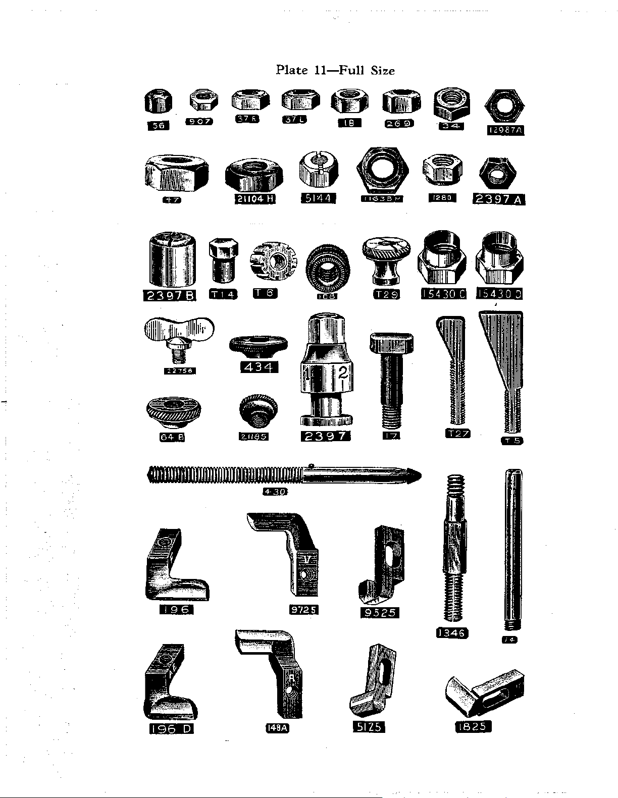
Plate
1-Full
Size
Page 11
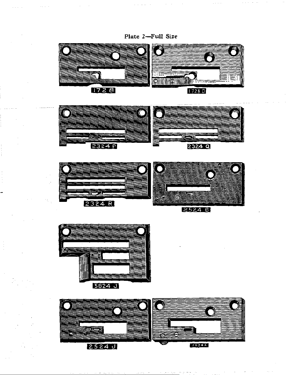
Plate
2-Full
Size
2324
R
Page 12
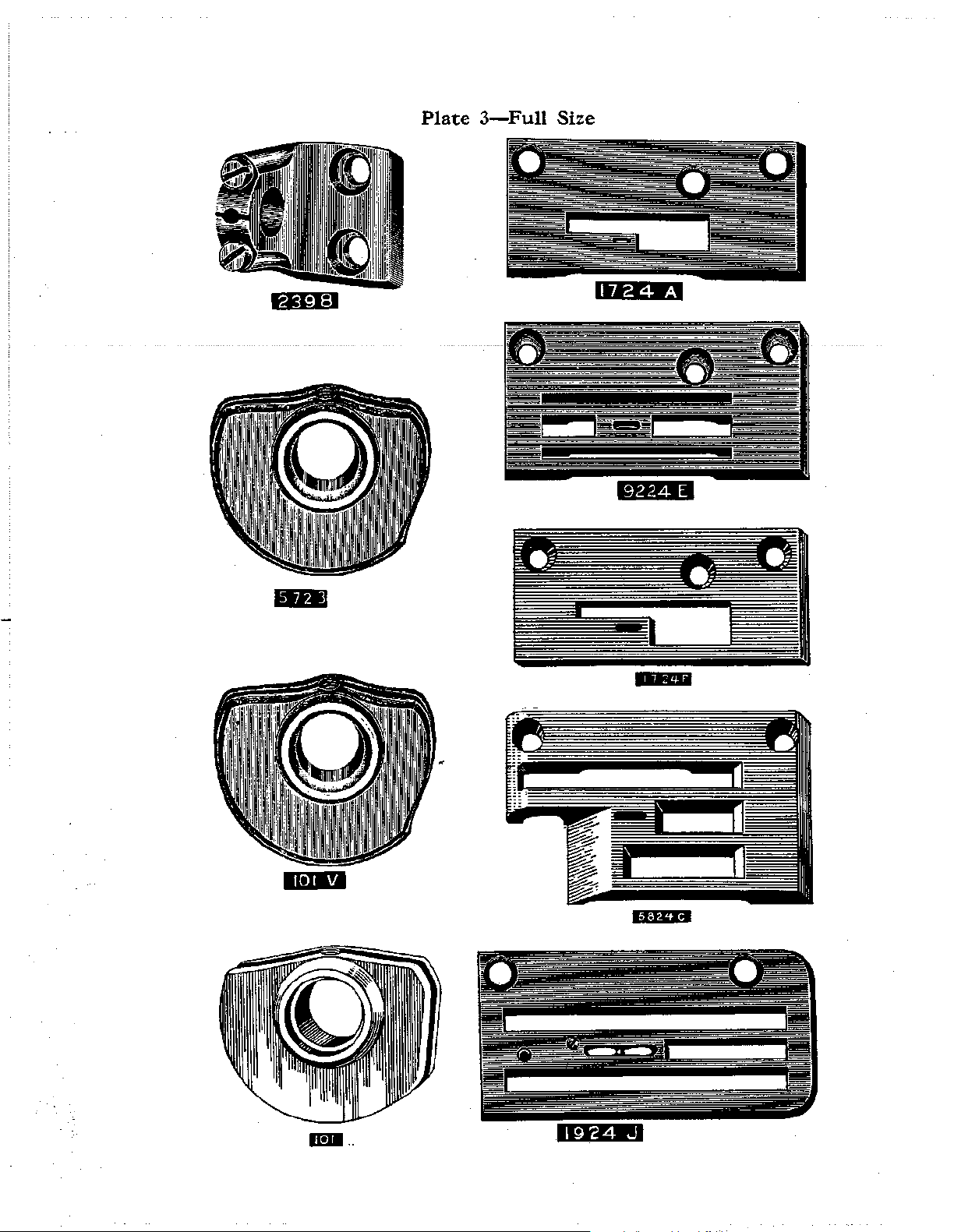
Plate
3-Full
Size
Page 13
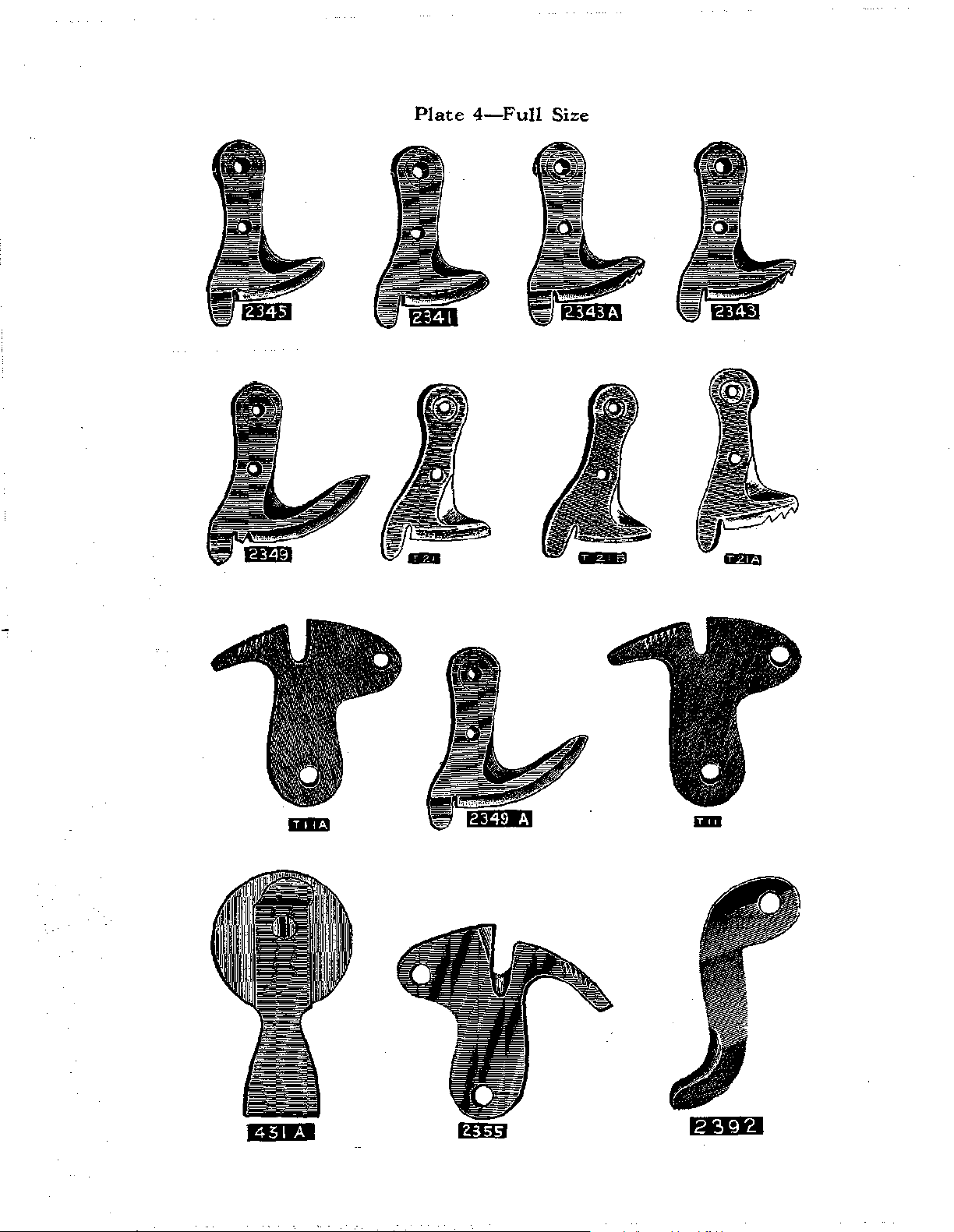
Plate
4-Full
Size
liD
Page 14

Plate
5-Full
Size
Page 15
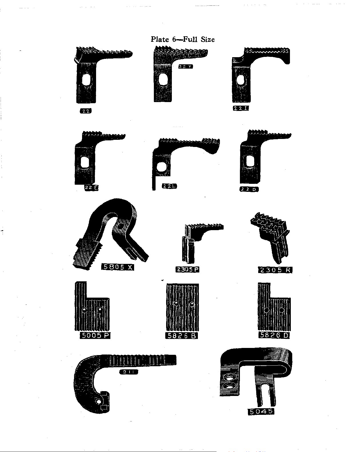
Plate
6-Full
Size
Page 16
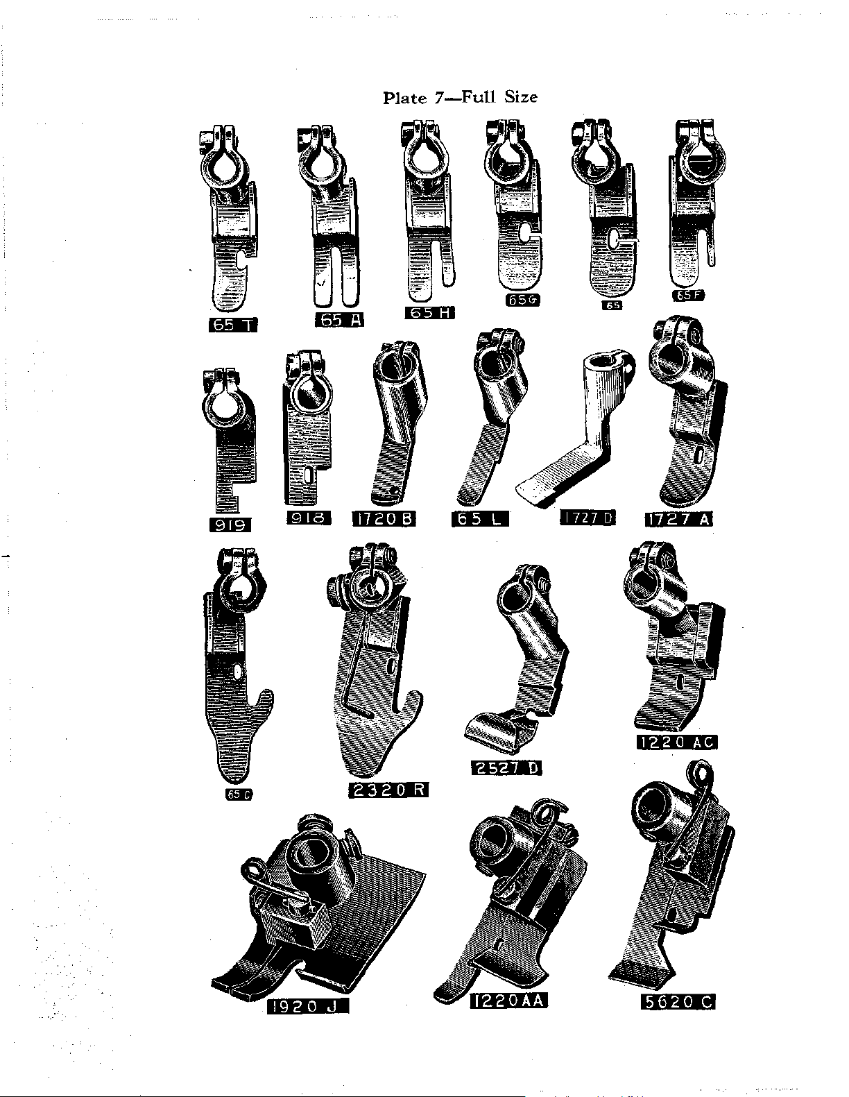
Plate
7-Full
Size
liiUII
Page 17
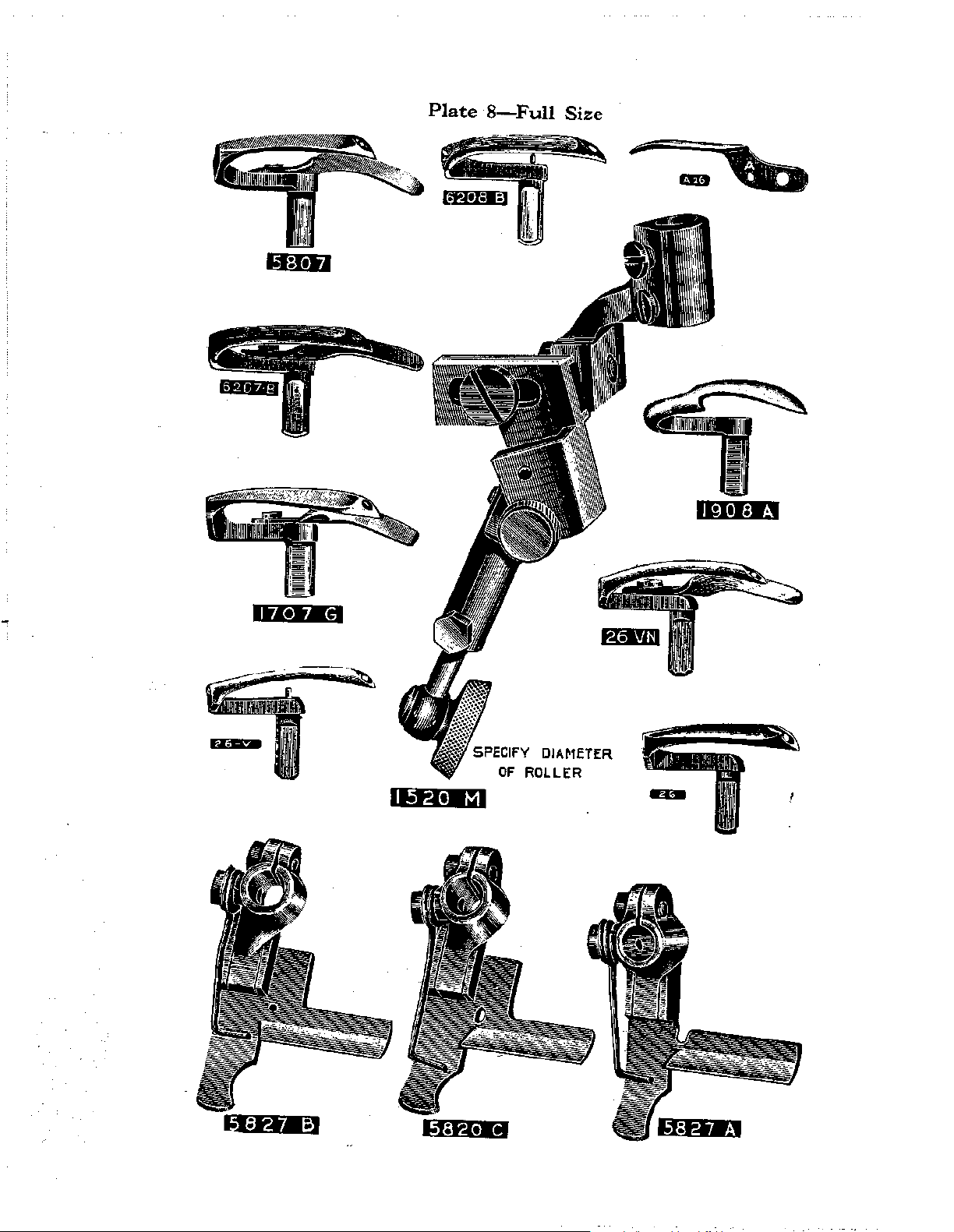
Plate
8-Full
Size
OF
ROLLER
Page 18
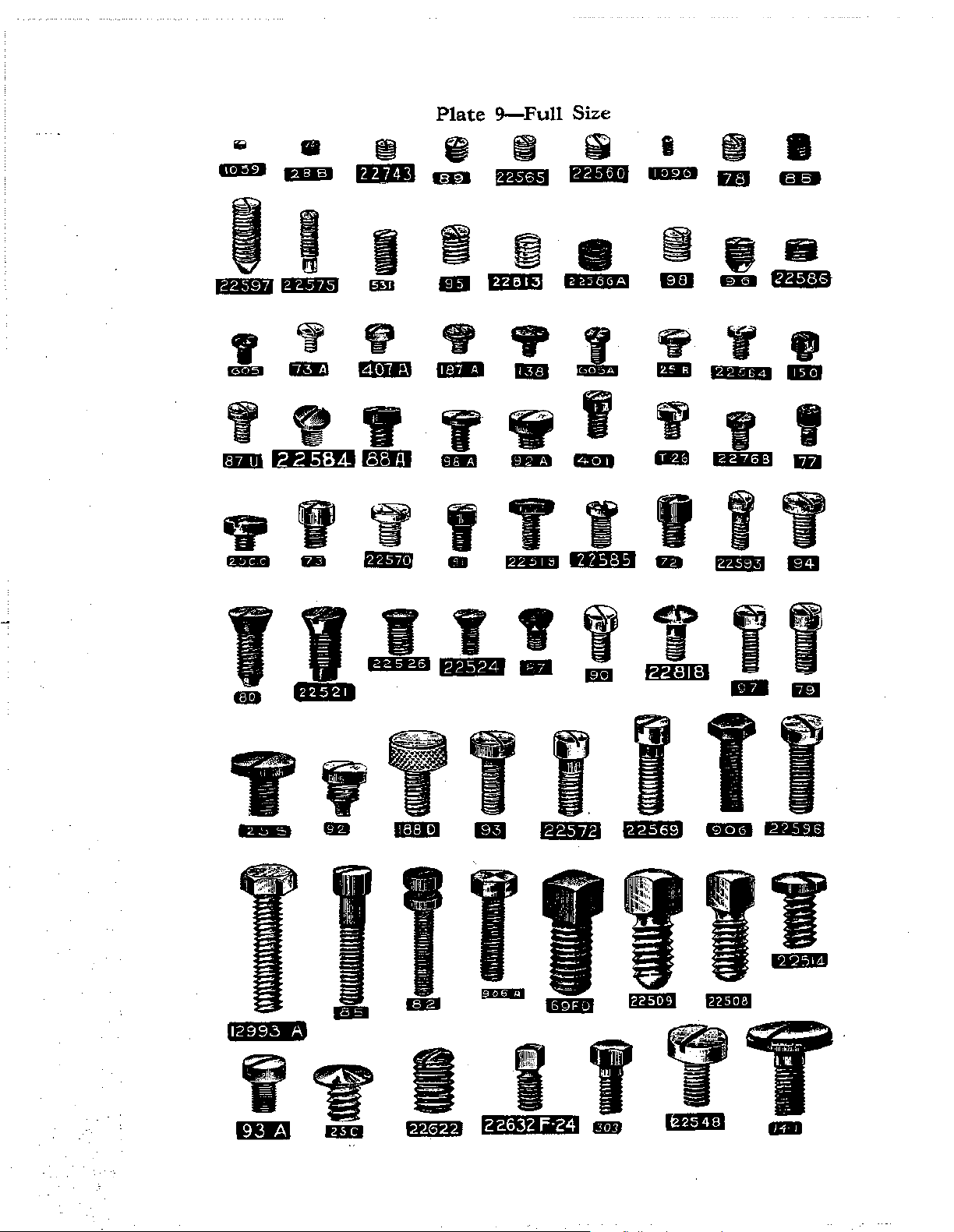
Plate
9-Full
Size
iii
mDJ
I
t.IAi#tj t4" ••i
m!S
II
H;l:l
I
mE
"
"
9
UD
f#r..ILi:!l
'
9
fB!D
I
-
~
tijjii
I
lliiD
e
~
I
~
tl'¥1
~
ft;j:IFJ
~
._,
,.,
•.
•
........
,
-
v
lltll!l
.,
tet;I!J
WITIIII
fBiJl
9
miD
y
llmEI
-
..
-
v
DB
..........
~
lmB1
IBiJ t.P.+i:e•
'
I
GI!D
1#!.1~1.1
~
&flil
..
I
~
Bml
t*.Hi:l
~
I;@
•
-
w
...
y
fi
tl4f;@
liD
'
t.P'¥8
..
"
I
m
miJ
'
T¥
5
--
-
.I.~!!
rl-4:11:1
..
''
-
''
.
I
22632 F-24
T
Page 19
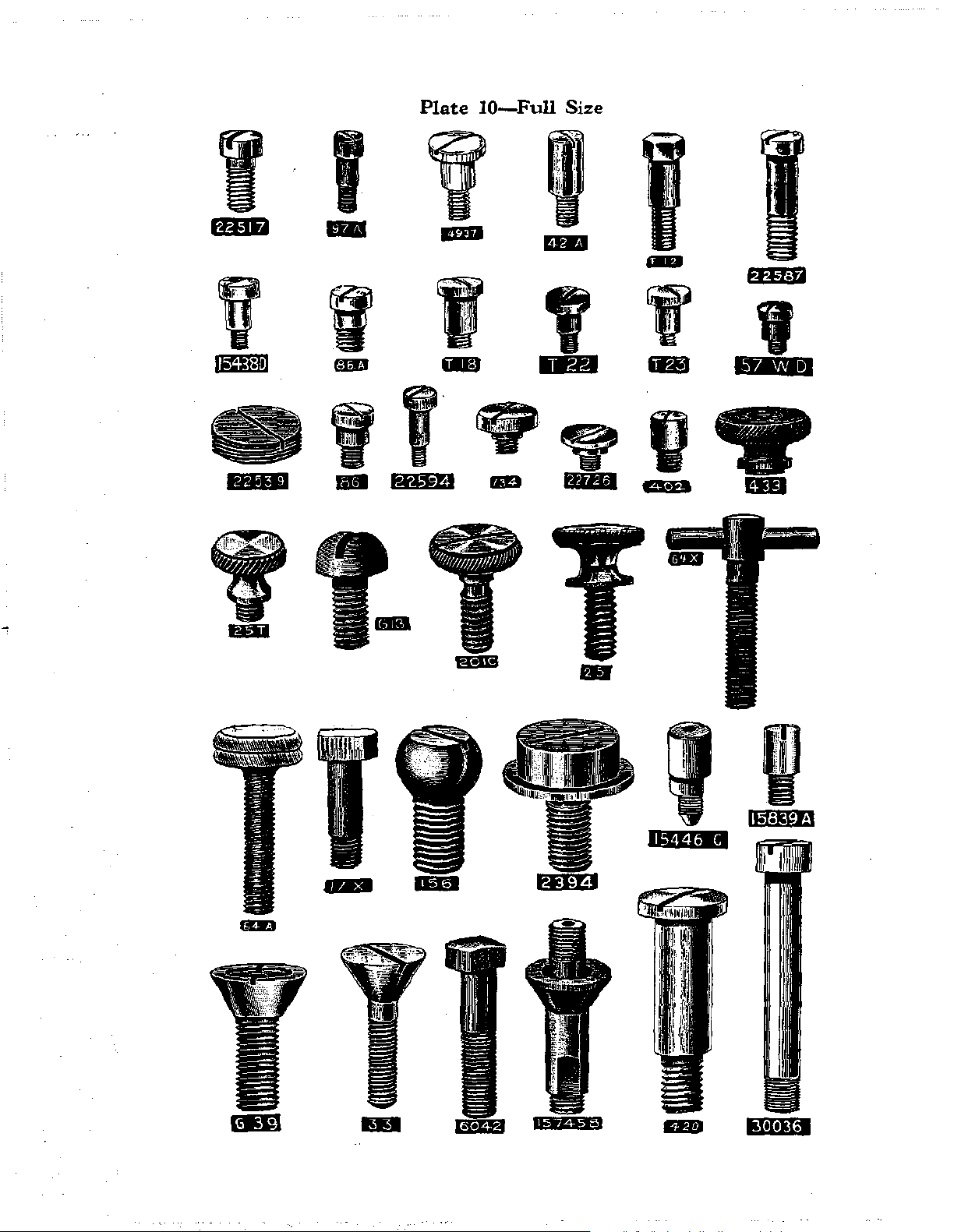
Plate
I I f
rt4-1N
1111
am
10-Full
Size
mB
OlD
.
v
l~il=J•J
.
v
GliB
I
..
·--~--~
'
~"""""
;~~;;;;£,~~~{
~"
lU
.
._,..,.-
,.,__""-~
20\C
i&)
'
.1'4t+ltl
'
.
.
I
Page 20
Plate
11-Full
MEII
Size
~~~~·
IQ1Ji
..
UI.JI
eiSEJ
Y04t
f1D
eo
·ma
ILjiiep
••+•P·•
0
4jiltlll
'
Page 21
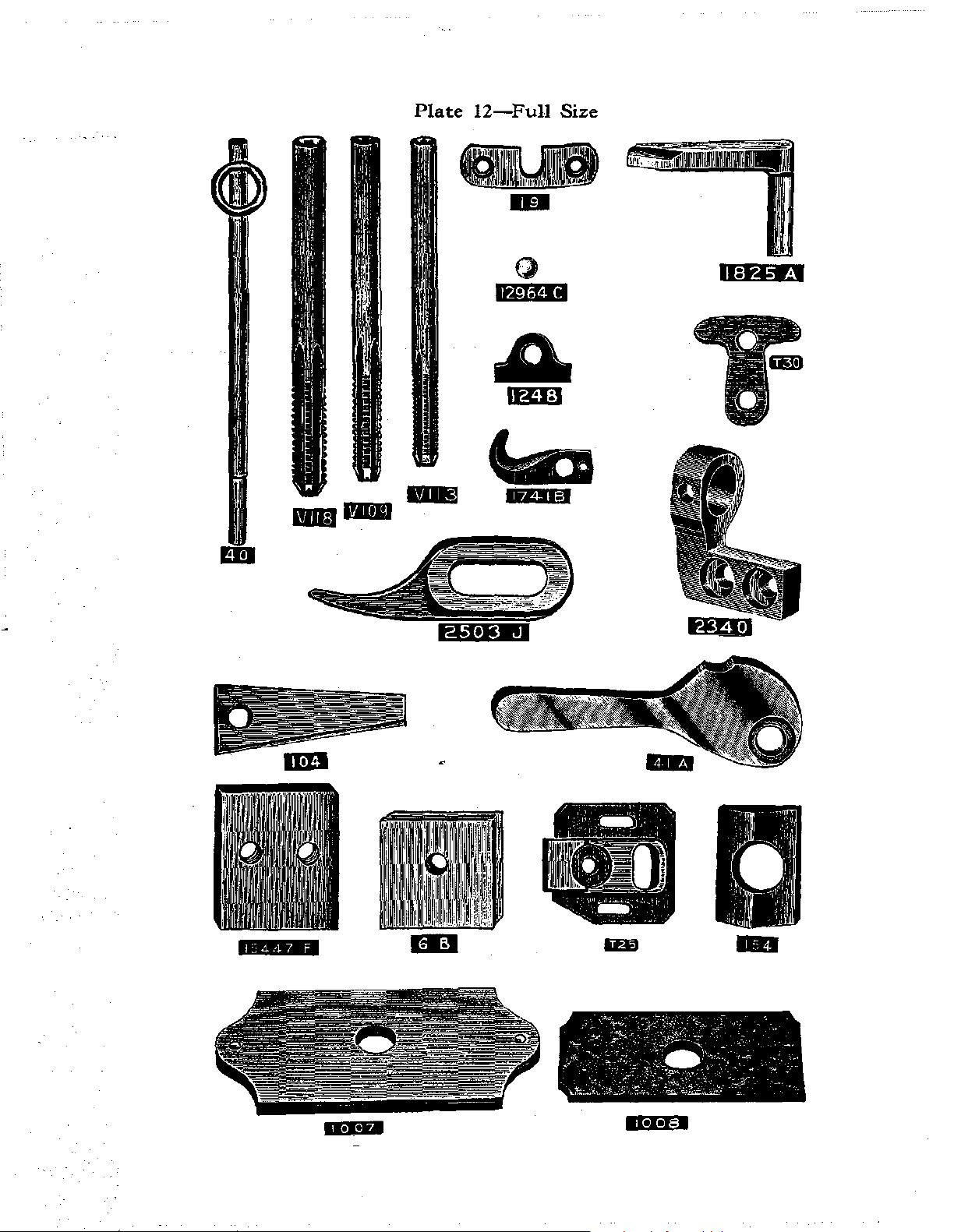
Plate
12-Full
··-
Size
lt~I:J
······=·
Page 22

Plate
13-Full
Size
J
...
,.
I
Net;
I
-
c.w••
•••
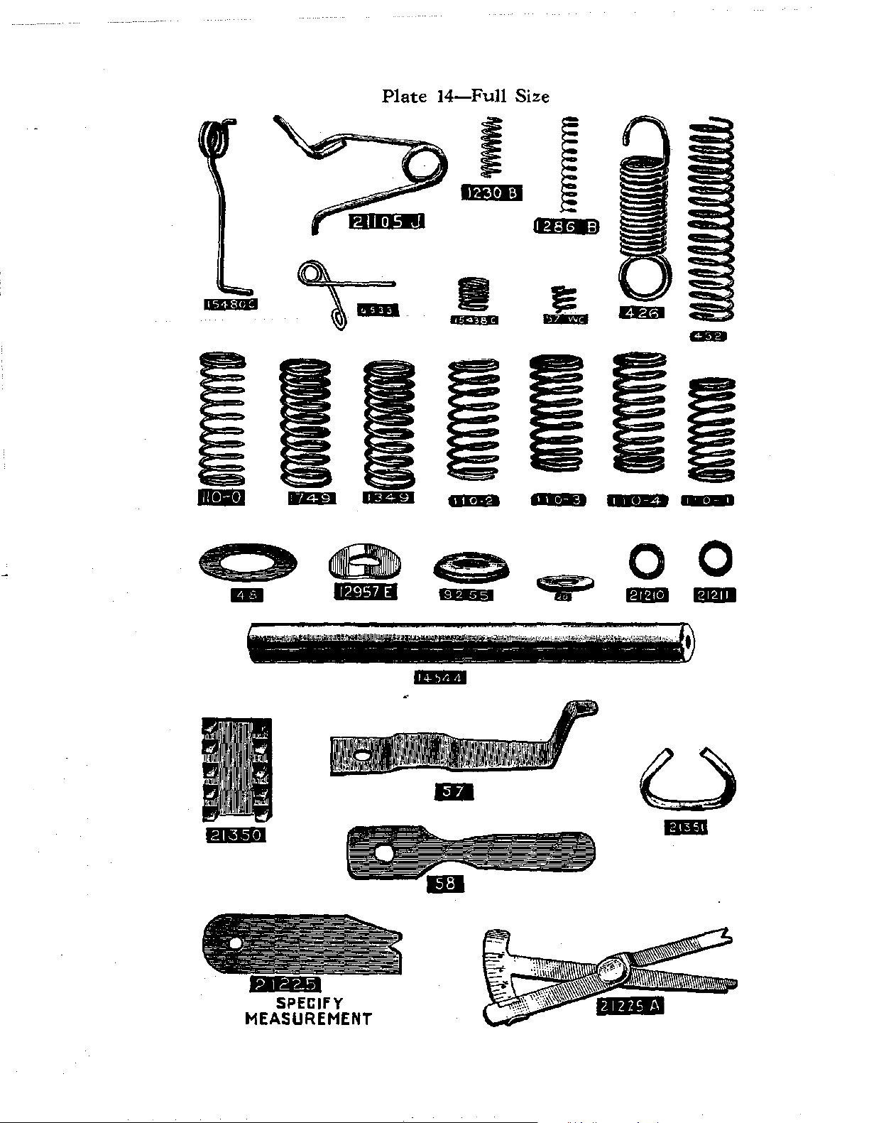
Page 23
••
-$1.:fi13
Plate
14-Full
I
lt41tl:.l
Size
¥&
f=
14
...
....=i=:j:::~
,.,.,.
~
----
.,
...
,
- - - -
..
:.::
...
"~''::~
- -
---=-~~~~-=~
--~-~--
~
•••••
oo
..
"''ii':,::.:.:.i,;,,,,,:l,)
--
-
...
SPECIFY
MEASUREMENT
Page 24

Plate
15-Full
Size
...
,
..•
,
Page 25

Plate
16-Full
Size
l:iWal
-~---
-
W I T
l'E;J
IB
lfJ@ellj
IHiiP-4
.
'
'
'
'
m
i@I:IM
I
I
I
ltd
•
-
Page 26

Plate
17-0ne-half
Size
..
•
I
lliitTiJ
Page 27

....
SPECIFY
MEASUREMENT
Plate
18-0ne-half
,,.,.,
Size
Page 28

".-~
--
--~ j
@iG€@1
'~
Plate
'
,,
19-0ne-half
;
j).
Size
......
23285
A
-7-z
23223
B
I
CID
.
I
t.i!ltiM•J
Page 29

Plate
20-0ne-half
Size
P.:l@ftil
r.41#1•M
Page 30

Plate
21~e-half
Size
6402
F
Page 31

..
,,,,.
Plate
22-0ne-half
Size
Page 32

-
Plate
23-0ne-half
,1
,,
Size
P.JIIIW;i
-
'.1
!I
:-
i
i
li
I'
!I
I
!
ilj
,
,
I
i
!
I
'I
,,
I
I
l#itiH
Page 33

Plate
li+j:ltf
24-0ne-half
.
j
Size
*i¥1*''
I,."Gitell
II
#II#]
Page 34

:::!i!illlii!IUI!!I!Iill!ili!!!lli!fiipllliil!!\llilll!llll!l\ll\lillmlrullm!IUIUIHIII
1
1¥W:I
Plate
25-0ne-third
Size
Specify
Length
Page 35

Plate
26-0ne-fourth
Size
...
,
...
•.:t•l.i
••••
FAt.:Cet.l
t..lt.:lehi
filt.ieiJ
.,.,.,.
q:let-1
f...lt.:.Ceti
Page 36

Plate
27-0ne-fourth
Size
.,
..
,,
23406
G-.!2
t-'II#J#t.l
IWtl:l
Page 37

A
fJIIe(ii!J
----
Plate
t.41Mt4
•
28-0ne-eighth
it~
t41t61;J
Size
'
i
t41Ct§@
t~U·II3
~
.(B!J
-
•
HIC§II4
t.<.tlfill•l
Page 38

Plate
29-0ne-eighth
Size
21118
A
..
,
...•.
Page 39

Plate
30
2375A
Toggle
Grinder
Assembly
1
Page 40

Symbol
to
Order
by
LIST
The
figures in the last column refer only
and are not
to
be used in ordering.
OF
PARTS
to
the plates illustrating the parts Plate
No.
1G
1GC
2
2A
2C
2S
2U
2CU
3
4B
4C
4E
4V
5
T5
6B
6E
T6
7
7C
7G
Cloth Plate, for Styles 1200
1200
Q,
1200 AD, 1700
2600 G, 2600
Cloth Plate, for styles in Class 2300. . . . . . . . . . . . . . . . . . . . .
Cloth
Plate
Cloth
Plate
2600].....
Cloth
Plate
Cloth
Plate
1200 C, 1200 G, 1200
Cloth
Plate
Cloth
Plate
2600G,
Cloth
Plate
Cloth
Plate
Cloth
Plate
Cloth
Plate
Cloth
Plate
Cloth
Plate
Styles
Cloth
Cloth
Cast-off Wire, for Styles 1200
1200 Q, 1700 A, 1700
Cast-off Wire, for Styles
5600 C, 5800 C, 5800 H, 5800
Cast-off Wire for Styles in Class 2300 . . . . . . . . . . . . . . . . . . .
Cast-off Wire for Styles 2600
2600H..........
Cast-off Wire Screw No. 22524.
Main
Main
Lower Toggle Adjusting Wedge, for sryles in Class
Looper Eccentric
Looper Eccentric
Looper Eccentric
Looper Eccentric
Looper Eccentric
Lower Toggle Adjusting Wedge
Feed
2600
Feed Rocker, for Styles 2300
Feed Rocker, floating design, for styles in Classes 1700, 2600,
5800,
1200 AC, 1200 AD, 1900
Feed Rocker Screws No.
1200 A, 1200 C, 1200 G, 1200
~K.~~~~~~~J................
Plate
Plate
Shaft
Shaft Collar Screws No. 95.
Rocker, non-floating design, for
H............................................
also Styles 1200
J......................................
Screws No. 80.
Slide, right, for Styles 1200
...
..
..
.. . .. .. .. ..
Slide Stop, Screw No. 150.
Slide, left; also cloth plate slide, right, for Styles
0,
Slide, right, for styles in Class 2300. . . . . . . . . . .
Slide, right, for Styles 1700
2600
H.....................................
Slide Thumbscrew No.
Hinged Cover
Hinged Cover
Slide, right, for Style 1900
Slide Stop Screw No. 150.
Guard, for styles
Guard
Guard
Collar. . . . . . .
Screw, front, No. 92
Screw, rear, No. 92.
•.
. . .
Fork
Shoe. . . . . . . . . . . . . . . . . . . . . . . . . . . . 12
Fork
Shoe Screw No.
Fork.
Fork
Set
Fork
Clamp Screw No. 85.
A,
1200 C, 1200 G, 1200
A,
1700 B, 1700 F, 1700 H, 2600 F,
A,
1200 AC, 1200 AD,
. .
.. .. .. .. .. .. .. .. . ..
1200 Q,1700
Latch.
Latch
in
Classes 1700, 2300; also for
A,
A,
1700
B..........
F,
1700
H,
25
T.
. . . . . . . . . . . . . . . . . . . . . . .
Screw No. 134.
K.
. . . . . . . . . . . . . . . .
0,
1200
Q,
1200 AC,
A.
1200 C, 1200 G, 1200
0,
2600 F,
0,
B..............................
1200
AA,
1200 AD, 1700 G, 2600
J.
. . . . . . . . . . . . . . . . . .
A,
2600 D, 2600
..... . ..
..
. . . . . . . . .
. . . . . . . . . . . . . . . . . . . . . . . . . . . . . . . . 22
Screws No.
A,
1200 C, 1200 G, 1200
K.
88.
. . . . . . . . . . . . . . . . . . . . . . 13
..
. . . . . . . . . . . . . . . . . 16
94.
72.
Nut.
. . . . . . . . . . . . . . . . . . . .
Styles~
A,
2300 B, 2300
. . . . . . . .
..
. . . . . . . . . . . . . .
M,
F,
F,
2300
0,
2300 . . . . .
J.
2600 G,
2600 G,
N.
. . . m
1200 Q,
..
29
29
.
21
21
21
21
19
21
m
13
13
13
11
11
22
. 27
38
Page 41

So::Jbol
to
derby
LIST OF PARTS
The
figures in the last column refer
and are not
~o
be used in ordering. ·
only
to
the plates illustrating the parts
Plate
No.
·.[
·\
7H
T7
8
I
8-408
8-410
8-413
•
8-416
8-419
8-422
SA
9C
9X
10
10
A Feed
11
T11 Lower Toggle, serrated one side, for Styles
T11 A Lower Toggle, serrated both sides, for
12
T12
13
Feed Rocker Arm, for use with feed rocker No. 7 G
Feed Rocker Arm
Screws No.
93.
Lower Toggle Adjusting Wedge Pin, for styles in Class
Feed Rocker
ground, standard diameter
floating design
Feed Rocker Shaft, standard diameter plus
Feed Rocker Shaft,
Feed Rocker
Feed Rocker
Feed Rocker
Feed Rocker
Feed Rocker Shaft,
design
Feed Bar, for Styles 2300
Feed Bar, for Styles 1200 C, 1200 G, 1200
1200 AD, 1700
2600H
Feed
Bar
Feed
Bar
Styles 1200
1200 AD, 2300
2600
Feed
Bar
Bar
Feed
Bar
styles with non-differential
Shaft, solid, 5
..fo
inches long, hardened and
.407 inch, fur styles with non-
feed
rocker
............................
.001
standard
diameter plus .003 inch
Shaft, standard diameter plus .006 inch
Shaft, standard diameter plus .009 inch
Shaft, standard diameter plus .012 inch
Shaft, standard diameter plus .015 inch
5fi
inches long, for styles with floating
feed
rocker
...................................
A,
2300 B, 2300 M, 2300 N
0,
1200 Q, 1200 AC,
A,
1700 B, 1700
F,
1700
G,
2600
.............................................
Screws No. 88.
Prong and Sponge, for styles in Class 1700; also
A,
1200 C, 1200 G, 1200
A,
2300
B, 2300
G, 2600 H, 2600 J
Prong Screws No.
Prong Sponge
..............................
94.
................................
Shaft, 3-tlr inches long, hardened
feed
0,
1200 Q, 1200 AC,
M,
2300
and
............•..........
2300
2300 N, 2300
P,
2300 Q
..............................
Styles 2300 M, 2300 R
Lower Toggle
Feed Crank Cover, for Style 1700 G
Feed Crank Cover Hinge
Screw, for lower toggles
Feed Crank Cover Spring, for Style 1700 G
Feed Crank Cover Spring Screw No.
Screw No. T12.
Screw No.
................................
.....................
N.
...............
94.
G13 Clamp Screw, for toggle grinder renewable bearing
Tl3
•
Tl3A
14
T14 Lower Toggle Nut, for styles in Class 2300
Lower Toggle Adjusting Bushing, long, for styles in Class
2300
...............................................
Lower Toggle Adjusting Bushing, short, for styles in Class
2300
...............................................
Hinge Screw, forfeed crank cover on Style 1700 G
...............
...
2300
inch
.......
.......
.......
.......
.......
.......
......
F,
2600
G,
N, 2600
F,
ground, for
A,
2300
B,
.........
..........
27
16
23
23
25
22
24
23
4
4
28
10
24
10
16
16
11
11
'
39
Page 42

LIST OF PARTS
Symbol
to
Order
15
16
G16
T16
17
17X
18
T18
19
T19
20
21
T21
T21A
T21 B
22
22D
22E
22 I
22L
22Y
T22
T23
24
24A
24S
25
The figures in the last column refer only
and
are
not
to
by
Feed
Crank Link, for styles in Classes 1200, 1700, 2300, 2600,
5600, 5800..
be used in ordering. No.
. . . . . . . . . . . . . . . . . . . . . . . . . . . . . . . . . . . . . . . .
to
the
plates illustrating the parts Plate
Feed Crank Link Shim No. 1248.
Feed Crank Link Screw,
Feed Crank Link
Nut
Feed Crank Link Screw,
H inch long, No. 22569.
No. 7947.
H inch long, No. 79, obsolete.
Feed Crank Link Ferrule. . . . . . . . . . . . . . . . . . . . . . . . . . . . . . .
Toggle Grinder Emery Wheel. . . . . . . . . . . . . . . . . . . . . . . . . . . 25
Toggle Grinder Emery Wheel Washer No. G54.
Toggle Grinder Emery Wheel
Trimmer
Trimmer
Feed Crank
5600, 5800.
Pitman
Pitman
Pin, for styles in Class 2300. . . . . . . . . . . . . 16
Pin
Screw No. 77.
Stud, for styles in Classes 1200, 1700, 2300, 2600,
. . . . . . . . . . . . . . . . . . . . . . . . . . . . . . . . . . . . . . . . .
Feed Crank Stud, for Style 1900
Feed
Crank
Trimmer
Feed Crank
2600, 5600,
Feed Crank
Trimmer
2300
Trimmer
Feed Crank
Feed Crank Link
Feed
Stud
Nut;
also for Nos. 36 R, 21168
Pitman
Screw, front, for styles
Stud
Cap, for styles
5800.....
Stud
Cap
Screws No. 77.
Pitman
Bracket, for Styles 2300
N.............................................
Pitman
Crank
Bracket Screws No. 22548.
Stud
Washer; also for No. 21168 A. . . . . . . . . . . . . 14
Pin.
. • . . . . . . . . . . . . . . . . . . . . . . . . . . . . . . . 16
Link
Pin
Screw No. 77.
Upper Toggle, for Styles 2300 B, 2300
Nut
No. G57
K.
. . . . . . . . . . . . . . . . . . . . . 10
in
Classes 1200, 1700, 2300,
A.
A.
. . . . . . .
in
Class 2300. . . . .
. . . . . . . . . . . . . . . . . . . . . . . . . . . . . . . . 12
A,
2300 B, 2300
Q.
. . . . . . . . . . . . . . . . 4
Upper Toggle, ! inch long, with three teeth, for styles in
Class
2300. . . . . . . . . . . . . . . . . . . . . . . . . . . . . . . . . . . . . . . . . . 4
Upper Toggle, for Styles 2300
A,
2300
N,
2300
P.
. . . . . . . . . 4
Upper Toggle Screw No. T22.
Feed Dog, for Style
Feed Dog, for Styles
Feed Dog, for Styles
Feed Dog, for Styles
Feed Dog, for Styles
Feed Dog, for Style
1200 0
1200 G, 1200 Q,1700
1700
1700
1200
2300
................
A,
1700
B,
A,
1200 C, 1200
A,
2300
B,
2600
2300 N . . . . . . . . . . . . . 6
,
..
F,
2600
J..............
AD
. . . . . . . . . . . . 6
H.............................
. . .
..
F,
2600 H 6
Feed Dog Screw No. 93.
Upper Toggle Screw, for styles
Upper Toggle Guide Screw. . .
Gauge, for Styles 1200
Gauge, for Style 1200
Gauge Screws
No.
Gauge, for Styles
A,
0................................
25.
1700
F,
in
Class 2300.. . . . . . . . . . . . . 10
.. .. .. . ..
. . .
.. .. ..
1200 C, 1200 G, 1200
1700 H, 2600
A,
2600
. . . . .
Q.
. . . . . . . .
F.
2600 G
Gauge Screw No. 25 S.
Thumbscrew, for
cloth
plate
gauges......................
15
16
11
11
10
M,
25
. . . . . 6
..
. 10
20
20
20
10
6
6
40
Page 43

so,_mbol
to
derby
LIST OF PARTS
The
figures in the last column refer only
and are not
to
be
used in ordering.
to
the
plates illustrating the parts
Plate
No.
25B
25C
25S
25T
25
T25
cc
Screw, for loop retainer in Styles 2600
2600 G, 2600 H
.....................................
Screw, h inch long, for cloth plate attachments
Screw, for cloth plate slide gauges; also
Thumbscrew, for cloth plate slides
Screw,
for
cloth plate hinged cover; also for Nos. 396 D, 2392.
Upper Toggle Adjusting Block, for styles in
UpperToggle Adjusting Block Guide
26
26
v
'
'
26 VN
A26
T26
27
v
27
X
T27
28
B
29
29
v
Looper, for styles in Class 2300; also Styles
1200G,
12000,
1200Q,1700A, 1700B
Looper, without guard, otherwise same
Looper, with
2600 G, 2600 H
Looper
Set
guard, for Styles 2600
.....................................
Screw No.
73.
Looper Needle Guard, for loopers Nos. 26 VN, 5807, 6207 B
Looper Needle
Guide
Screw, for upper toggle adjusting block, on styles in
Class 2300
Guard
..........................................
Loop Retainer, for Styles 2600
2600H
.............................................
Loop Retainer Screw No.
Loop Retainer Adjusting
Loop Retainer, for
Loop
Retainer
Screw No. 87 U.
Loop Retainer Adjusting
Screw No. 73
A,
25
B.
Screw, h inch long, No.
Style 1900 K
.........................
Screw No. 1096.
Upper Toggle Adjusting Wedge, for styles in
Upper Toggle Adjusting Wedge
Upper Toggle Adjusting Wedge
Adjusting
Screw, h inch long, for loop retainer
Nut
Set Screw No. 22570.
Looper Rocker, hardened, for Style 1900 K
Looper Rocker, hardened, for Styles 1200 AC, 1200 AD,
1700
F,
1700
G, 2600
A,
2600 D, 2600 F, 2600 G, 2600 H
T29 Upper Toggle Adjusting Wedge Nu.t, for styles in Class 2300.
30
Looper Rocker Frame, integral cone, hardened
Looper Rocker Frame
Screw, left, No.
A,
2600 D, 2600
............
for
No.
21163
.......................
Class 2300
Screws
No.
1200
T26.
A,
..................
as
No.
26
VN
A,
2600 D, 2600
A.
2600 D, 2600
F,
Class 2300
No. T29.
...........
...............
............
88.
......
.....
1200
......
2600 G,
28
B.
..•
....
F,
C,
F,
..
9
9
9
10
9
12
8
8
8
8
9
13
13
11
9
25
25
11
22
Looper Rocker Frame Screw, right, No. 98.
Looper Rocker Frame
T30
31
Upper Toggle Guide Screw Washer, for styles in Class 2300
Looper Rock
Shaft,
standard diameter
31-408
31-410
Looper Rock Shaft, standard diameter, plus
Looper Rock Shaft, standard diameter, plus .003 inch
31-413 Looper Rock Shaft, standard diameter, plus .006 inch
31-416 Looper Rock Shaft, standard diameter, plus .009 inch
31-419 Looper Rock Shaft, standard diameter, plus .012 inch
31-422 Looper Rock Shaft, standard diameter. plus .015 inch
G31
Toggle Grinder Frame
Spot Screw No.
3l
inches long, hardened and ground,
.407 inch
...........................
96.
.001
inch
.................................
......
......
......
......
......
......
...
12
23
30
41
Page 44

LIST OF PARTS
Symbol
to
Order by
32
32-408
32-410
32-413
32-416
32-419
32-422
G32
33
G33
34
G34
35
G35
G36
t36
L
t36
R
37 L
37 R
38
38
v
G38 A
G39
40
G40
G41
41
A
The figures in the last colwnn refer only
and are
not
to
be used in ordering.
to
the plates illustrating
the
parts Plate
No.
Looper Rock Shaft, 1 i-inches long, hardened and ground,
standard diameter,
Looper Rock Shaft, standard diameter, plus
Looper Rock Shaft, standard diameter, plus
Looper Rock Shaft, standard diameter, plus
Looper Rock Shaft, standard diameter, plus
Looper Rock Shaft, standard diameter, plus
Looper Rock
Shaft, standard diameter, plus
Toggle Grinder Frame Slide.. .
Looper Rocker Stud, hardened,
.407 inch. . . . . . . . . . . . . . . . . . . . . . . . . . 23
.001
inch
.....
.
..
1h
.. ..
inch
.003 inch
.006 inch
.009 inch
.012 inch
;015
..
. . . . . . .
diameter..........
inch
..
. .
.....
.....
.....
.....
.....
.. ..
.
.
.
.
.
..
. 30
10
Toggle Grinder Frame Slide Adjusting Screw. . . . . . . . . . . . . 30
Looper Rocker
No. 12993
Toggle Grinder Frame Slide
Stud
Nut,
for use
A.
. . . . . . . . . . . . . . . . . .
Gib....
with.;,.
..
. . . . . . . .
..
. . . . . . .
inch stud; also for
..
..
. . . . . . .
.. . ..
. .
..
. . . 30
11
Toggle Grinder Frame Slide Gib Screws No. 22575.
Looper
cOnnecting Rod,
2300, 5800; also Styles 1200
2600
A,
2600 D, 2600
Toggle Grinder
Clamp.................................
Toggle Grinder Clamp Screw No.
Toggle Grinder Clamp
Looper Connecting Rod Ball
Looper Connecting Rod Ball
Looper Connecting Rod Ball
Looper Connecting Rod
Looper Connecting Rod
6i
inches long, for styles in Classes
A,
1200 AD, 1700 G, 1900 K,
F,
2600 G, 2600
Pivot
Pin.
Joint
Joint
Joint
Nut,
left thread. . . . . . . . . . . . . . . . .
Nut,
right thread. . . . . . . . . . . . . . . .
201
H...............
C.
. . . . . . . . . . . . .
Assembly,
Assembly,
left..........
right........
Screws No. 97 A.
..
. . . . . .
..
23
30
30
17
17
11
11
Looper Eccentric, ground, for styles in Classes 2300, 5600;
also Styles 1200 A, 1200 C, 1200 G, 1200
1700 B, 5800 C, 5800
H.
. . . . . . . .
Looper Eccentric, ground, for Styles 1200
1700
F,
1700
H,
2600
J.....
1000 K, 2600
.....
..
..
..
A,
.. .. . .. .. .. .. . ..
0,
1200 Q, 1700
..
. . . .
..
..
..
AA,
2600 D, 2600 F,
.. .. .
A,
. . . . . .
..
1200 AC,
2600
G,
..
....
.. 16
.
16
Looper Eccentric Screw No. 96.
Toggle Grinder
Toggle Grinder
Toggle Grinder
Table. .
Turn
Table Pivot Stud. . . . . . . . . . . . . . . . . . . 10
Turn
Table Pivot
.. . ..
Stud
. . . . . . . . . . .
Nut
No. 11638 M.
..
. . . . . . . . . 30
Turn
Frame Looper Thread Guide, lower, right. . . . . . . . . . . . . . . . 12
Turn
Toggle Grinder
Toggle Grinder
Toggle Grinder Tilting
Hand
Lifter, hardened, for styles
1200A, 1200C, 1200G,
A,
1700
2300
2600
Hand
1700 B, 1700
M,
2300
J,
5600
Lifter
Stud
Table Tilting Block. . . . . . . . . . . . . . . . . 30
Tum
Table Tilting Block Screw No. 96.
Shaft..
P,
2300 Q, 2300 R, 2600 F, 2600 G, 2600 H,
. . . . . . . . . . . . . . . . . . . . . . . . . . 30
in
Class 5800; also Styles
12000,
F,
1700
1200Q, 1200AA, 1200AC,
H,
1900 K, 2300
A,
2300 B,
c......................................
No. 86.
12
tSeePage7
42
Page 45

LIST OF PARTS
Symbol
to
Order
42 A
43
43
c
43 X
G43
G44
G46
47
G47
48
G48
G49
50D
G50
51
G51 A
52 A
G52
53
A
The figures in the last column refer only
by
and are not
Hand
Feed
Lift
also Styles 1700
2300 N
Feed
2600
Feed
Lift
Feed
Lift
Toggle
,Toggle
Toggle
Toggle
Needle Lever
Toggle Grinder Pulley
Toggle
Needle
Toggle Grinder Spindle, hardened
Toggle Grinder Spindle Renewable Bearing, lower,
Needle Bar, hardened
inch, for styles in Classes
also Styles 1200 C, 1200 G, 1200
1200 AC, 1200
Needle
Needle
Toggle
Toggle Grinder Spinclle RenewableBearingCoverScrewsNo.88.
Needle
5800;
1200 AC, 1200 AD, 1900 K
Toggle Grinder Spindle
Toggle
Needle
2300, 5600, 5800;
frame
2600
Thread
Toggle
Toggle
Needle
2300, 5600, 5800;
Needle
2300, 5600, 5800,
1200 Q, 1200 AA, 1200 AC, 1200 AD, 1900
2600 ], No. 22768.
Needle
605A.
to
be used in ordering.
Lifter
Screw Pin, hardened
Eccentric, ground, for styles
A,
1700 B,
............................................
Lift
Eccentric, ground, for Styles 1700
F,
2600 G, 2600
Cam,
hardened
Cam
Screw No. 96.
Grinder
Grinder
Grinder
Grinder
Grinder
Lever
Bar
Bar
Grinder
Bar
also Styles 1200 C, 1200 G, 1200
Grinder
Lever
thread
F,
Eyelet
Grinder
Grinder
Bar
Bar
Bar
Tilting
Tilting
Knife
Turn
Stud
Pulley Screws No. 88.
Stud
Set
Screws, headless, No. 88.
Set
Screws, fillister head, No.
Spindle Renewable Bearing Cover, left
Connection, for styles
Spindle
Thread
eyelet, for Styles 1900
2600 G, 2600 H .
Screw No. 98
Spindle Collar
Spindle Collar Screw
Thread
Thread
Thread
H,
and
Shaft
Shaft
Clamp
Table
Nut.
..............................
.................................
Washer
and
AD
..................................
Cap
Cap
Eyelet, for styles
also Styles 1900 K, 2600 H, 2600 J
Guide, for styles
also Styles 1900
Guide
and
Guide Screw, for Style 1200
to
the plates illustrating the parts
............
in
1700G,
2600 J
Arm
Arm Screw No. 96.
Stop
Spring
............................
ground,
1700, 2300, 2600, 5600, 5800;
2300A, 2300 B, 2300 M,
......................
ground, for Style 1900 K
......................
Screw
Pin
..................
and
ground
standard
0,
in
Classes 1700, 2€00, 5600,
,
Classes 1200, 5600;
Support
............
diameter
1200 Q, 1200 AA,
88
A.
0,
1200 Q, 1200 AA,
.........................
..........................
Screws No. 88.
in
Classes 1200, 1700,
K,
2600
............................
A.
..........................
No.
22560.
in
Classes 1200, 1700,
K,
2600
H,
Screw, for styles h Classes 1700,
Styles 1200 C, 1200
..........
F,
1700
.........
right
A,
2600
2600 J
G,
1200
K,
2600
A,
H,
...
...
.257
.....
and
D,
.....
0,
H,
No.
..
..
Plate
No.
.
10
.
16
.
16
.
16
.
30
.
30
.
16
.
11
.
30
.
14
.
30
.
30
.
23
30
24
30
.
13
.
30
13
43
. i
Page 46

LIST OF PARTS
Symbol
to
Order
The figures in the last column refer only
by
and are
not
to
be used in ordering. ·
to
the plates illustrating the parts Plate
-----------------------------------------------1----
Oiler.
G53
54
G54
G55
56
G56
57
57 WB
we
57
57 WD
G57 A
58
v
59
59
X
60 A
60 A-322
60 A-325
60 A-328
60
A-331
60 A-334
c
60
60
X
60 X-322
60 X-325
60 X-328
60 X-331
60 X-334
61
c
62
62-322
62-325
62-328
62-331
Toggle Grinder Spindle
Needle Lever Link, hardened
Toggle Grinder Emery Wheel Washer
Toggle Grinder Emery Wheel Guard, left
..........................
...........................
.............
...............
Toggle Grinder Emery Wheel Guard Screws No. 531.
Needle Clamp Nut, hardened
Toggle Grinder Emery Wheel Guard,
Toggle Grinder
Emery
Looper Thread Nipper Spring, upper.
Looper Thread Nipper Spring Screw No.
Needle Bar Thread Nipper Plate
Bar
Needle
Thread Nipper Spring. . . . . . . .
..........................
Whee!
Guard Screws
.......................
right
..............
No.
93
...................
90.
.............
A.
Needle Bar Thread Nipper Stud; also for No. 15480 C
Nut
Toggle Grinder Emery Wheel
Looper Thread Nipper Spring, lower.
Looper Thread Nipper Spring Screw No.
Looper Thread Nipper Spring Operating Screw No.
Eccentric Pulley, throw
.461
Eccentric Pulley, throw .634 inch, for Style 1900
......................
...................
90.
97.
inch, for Styles 1200 AC, 1700 F.
K.
Eccentric Pulley Screws No. 22597.
Presser Bar, hardened and ground, standard diameter .319
for
inch,
styles in Classes
Styles 2600 F, 2600
Presser Bar, standard diameter, plus
Presser Bar, standard diameter, plus .006 inch
Presser Bar,
standard
Presser Bar, standard diameter, plus .012inch
Presser Bar, standard diameter, plus .015 inch
1200,
1700, 2300, 5600, 5800; also
G,
2600
H,
2600
diameter, plus
1 .
...............
.003
inch
.009
inch
...........
...........
...........
...........
...........
Presser Bar, hardened and ground, standard diameter .319
A,
inch, for Styles 2600
Presser Bar,
.harden~d
inch, for Style 1900
2600 D
and ground, standard diameter .319
K.
..............................
Presser Bar, standard diameter, plus .003inch
Presser Bar, standard diameter, plus .006 inch
Presser Bar, standard diameter, plus .009 inch
Presser Bar, standard diameter, plus
Presser Bar, standard diameter, plus .015 inch
Presser Bar Connection, for styles in Classes
2600, 5600, 5800
Bar
Presser
Presser
Connection Screw, front, No.
Bar
Connection Screw, rear, No. 88.
....................................
Presser Guide Bar, hardened
E?tyle
.319 inch, for
Presser
Gu.ide
Bar, standard diameter, plus .003 inch
1900 K
Presser Guide Bar, standard diameter, plus
......................
...........
...........
...........
.012
inch
...........
...........
1200, 1700,
77.
and
ground, standard diameter
..........................
.006 inch
Presser Guide Bar, standard diameter, plus .009 inch
Presser Guide Bar, standard diameter, plus .012 inch
:
.....
....
......
2300,
.....
.....
......
......
.
.
.
.
.
.
.
.
.
.
.
.
.
.
.
.
.
.
.
.
.
.
.
.
.
.
.
.
.
.
.
.
No.
30
17
30
30
11
30
14
13
14
10
30
14
18
18
23
23
23
15
23
44
Page 47

Symbol
to
Order
by
The
furores
ana are not to
LIST OF PARTS
in the last column refer only
be used in ordering.
to
the plates illustrating the parts
·.
Plate
No.
62-334
62 A
62 A-322
62 A-325
62 A-328
62 A-331
62 A-334
62
c
62 C-322
62
~325
62
~328
62~1
62
~334
63A
63B
64
64A
64B
64X
65
65 A
65 c
65F
65G
65 H
65L
65T
66
66-531
66-533
66--536
66-539
66--542
Presser Guide Bar,
Presser Guide Bar, hardened
.319 inch, for styles in
2600 A, 2600 D
Presser Guide
Presser Guide Bar,
Presser Guide Bar,
Presser Gtlide
Presser Guide Bar,
Presser Guide Bar, hardened
.319 inch, for styles
1200A, 1200
2600
F,
2600
Presser Guide Bar,
Presser
Presser
Gt1ide Bar,
Gt1ide Bar,
Presser Guide Bar,
Presser Guide Bar,
Presser Spring, for Styles
1700A,
1700B,2300A,2300
standard
diameter, plus .015 inch
and
ground,
Class 5800; also Styles 1200 AD,
....................................
Bar,
standard
standard
standard
Bat,
standard
standard
in
C,
1200
G,
2600 H, 2600 J
standard
standard
standard
standard
standard
diameter, plus .003 inch
diameter, plus .006 inch
diameter, plus .009 inch
diameter, plus .012 inch
diameter, plus .015 inch
and
ground,
Classes 1700, 2300, 5600; also Styles
G,
1200
0,
1200 Q, 1200 AA, 1200 AC,
......................
diameter, plus .003 inch
diameter, plus .006 inch
diameter, plus .009 inch
diameter, plus .012 inch
diameter, plus .015 inch
1200 C, 1200 G, 1200
B,
2300P,
standard
standard
2300Q,
.....
diameter
.....
.....
......
.....
.....
diameter
.....
.....
......
.....
.....
0,
1200 Q,
5600C
....
Presser Spring, for styles in Classes 2800, 5800; also Styles
1200 A, 1200
2300
M,
Presser Spring
Presser Spring
Presser Spring Regulating Screw, for
1700, 2300,
Presser Spring Regulating Screw Lock
Presser Spring Regulating Screw, for Style
Presser Foot, for Style 1200 A
Presser
Foot,
Presser Foot, for Styles
2300
P,
2300 Q
Presser
Foot,
Presser Foot, for
Presser
Presser
Presser
Presser
Main
Foot,
Foot,
Foot,
Foot
Shaft, hardened
inch, for styles
Main
Shaft,
Main
Shaft,
Main
Shaft,
Main
Shaft,
Main
Shaft,
AA,
1200 AC, 1700
2300
N,
Rest
Rest
2600,
2300 R
...................................
Screw No. 88.
5600,
............................
5800
...........................
for Styles 1200 C, 1200
2300
.................
for Style 1200 0
Style
1200 G
for Style 1200 Q
for Style 1700 B
for Style 2600 F
Clamp
Screw No. 91.
and
in
Classes 1200, 1700, 2300, 2600, 5600, 5800
standard
standard
standard
standard
standard
diameter, plus .001 inch
diameter, plus .003 inch
diameter, plus .006 inch
diameter, plus .009 inch
diameter, plus .012 inch
............
ground,
F,
1700
H,
styles
in Classes 1200,
Nut
..............
1900
K.
.........................
AD
................
A,
2300 B, 2300 M, 2300
: .
...................
.........................
.........................
..........................
..........................
,
.............
standard
diameter .530
............
............
.....•.......
............
............
.
1900
.......
K,
N,
.
.
23
.
.
.
.
.
.
23
.
.
.
.
.
25
.
25
24
.
.
10
.
11
.
10
.
7
.
7
.
7
.
7
.
7
.
7
.
7
.
7
25
.
.
.
.
45
Page 48

LIST OF PARTS
Symbol
to
Order
67
68
68B
69 s
0 69
70
70
72
73
73
77
78
79
80
82
84
84 B
85
86
86
87
87
88
88A
89
90
91
92
92
FD
A
A
A
A
u
A
The
figures in the last column refer only
and are
not
to
be
by
Main
Shaft
used_
Sleeve, left, 1
1200, 1700, 5600; also Styles 2300
~~~~~~~a~J
Main
Shaft
Sleeve, right,
Main
Shaft
Thread
Sleeve,
Stand
1H
Pin, 4 inches long, for styles
1700, 2300, 2600, 5600, 5800.
Screw, square head, cup point,
to
inch, t inch long, for
21104
D,
21685, 21693
Looper Eccentric Sponge Holder
in ordering. ·
-fi-
1H
inches long,
F,
to
the plates illusrtating the parts Plate
inches long, for styles
A,
2300 B, 2300
in
Classes
............... w
inches long with
without
. . . . . . . . . . . . . . . . . . . . . . . . . 28
rlf
inch
diameter, 18
thread
21693
stand
seats; also for Nos.
K.
. . . . . . . . . . . . . . . . . . . . 9
and
Sponge. . . . . . . . . . . . . . 24
lug........
lug..........
in
Classes 1200,
threads
Looper Eccentric Sponge Holder Screw No. 93.
Looper Eccentric Sponge
Set
Screw, for looper eccentric
Set
Screw, fillister head, for loopers. . . . . . . . . . . . . . . . . . . . . . 9
..............................
fork......................
Screw, for looper needle guard, also for No. 1742. . . . . . . . . . 9
Screw, for feed
1286A........................
Screw, lower, for needle lever link pin.
Clamp
Screw, for needle
Screw, for cloth
Screw, for regulating length of
Stitch
Regulating Ferrule, for Styles 1200 AA, 2600
2600
D,
5800
J.............................................
Stitch Regulating Ferrule, for styles
also for Styles 1200 A, 1200 C, 1200 G, 1200
2600
crank
stud
plates.
F,
. . . . . . . . . . . . . . . . . . . . . . . . . . . . . . . . 9
2600 G, 2600
caps; also for Nos. T16, 21,
...
.. . .. . ..
. . . . . . . . . . . . . . . . . . . 9
rear
guard
in
Style 1200
stitch...........
H,
5600 C, 5800 C, 5800
in
Classes 1700, 2300;
. . . . .
AD.
. . . . . . . . . . 9
0,
1200 Q,
1200 AC, 1200 AD, 2600 J.. . . . . . . . . . . . . . . . . . . . . . . . . . . 16
Clamp
Stud,
Screw, plus size, for
Screw, for
Screw, for needle
Screw, for looper eccentric fork. . . . . . . . . . . . . . . . . . . 9
for
hand
lifters; also for No. 403. . . . . . . . . . . . . . . . . . .
hand
throat
21390 D
...........................
2366 B, 2366
lifters,
plates; also for Nos. 148 A, 196, 196 D, 9725,
thread
E,
5005
take-up
P,
tap
No.
V113............
:................
wire; also for Nos. 27
5805 X, 5826
B,
5826 D, 21607,
21608..............................................
Screw, headless, for feed rockers; also for Nos.
G50, G51
4517, 8648, 15063, 15465
Set
Screw, fillister head, for needle bars; also for No. 6440. . . . 9
Screw, for looper
Screw, for looper
2305 R, 15447
Clamp
A,
61 C, 64, 217, 406 B, 1288, 1917 K, 1920 K,
F,
21113 B, 21161
thread
thread
L,
take-ups..
. . . . . . . . . . . . . . . . . . . . . . 9
nipper springs; also for Nos. 2305
21390
E.
. . . .
.. ..
. . .
Screw, for presser feet. . . . . . . . . . . . . . . . . . . . . . . . . . . 9
30, G47, 50 D,
D.
. . . . . . . . . . . 9
.. ..
. .
.. ..
. .
Screw, rear, for cloth plate guard. . . . . . . . . . . . . . . . . . . . . . . . 9
Screw, front, for cloth plate
guard.
. . . . .
.. . .. .. . ..
..
No.
M,
16
16
.
61
C,
.. ..
. 9
. . . . . 9
A,
H,
16
10
10
X,
P,
..
. . 9
. .
..
. 9
9
9
9
D See page
7.
46
Page 49

LIST OF PARTS
S~bol
to
Order
93
The figures in the last column refer only
by
and are
not
to
be used in ordering. · No.
to
the
Screw, for feed dog in Styles 1200 C, 1200 G, 1200
plates illustrating the parts Plate
0,
1200 Q,
1200AC, 1200AD, 1700A, 1700B, 1700 F, 1700G, 2600F,
93
A
94
95
96
97
97
A
98
98 A
99
100 B
2600 G, 2600 H, 26001 and under feed dog in Styles 2600
2600 D, 5800C,
5650, 5842
Screw, for feed dog in Styles 1200
2300 B, 2300 M, 2300
...
1905 J. 233o,
A,
5800H,
7638
5045,
5800];
A,
15447
N;
also for Nos. G56, 419
15447
also for Nos.
F,
15447
A,
1700 H, 1900
K . . . . . . . . . . . . . . . . . . . . . . . . . 9
7H,
K...
. . . . . . . . . . . . . 9
K,
A,
Screw, for looper eccentric fork shoe; also for Nos.
113, 113
A,
202 A, 404
A,
539, 1825, 1941, 2340, 5132, 9932,
21602..............................................
Screw, for main shaft collar; also for No.
1005.....
Screw, for looper eccentrics; also for Nos. 30, G40, 43,
43
X, G43, 917,
Screw,
H inch long, for supporting feed dogs; also for Nos.
103, 403, 2334, 17158. . . .
58,
2306................................
..
. . . . . . . . . .
..
. .
.. ..
Screw, for looper connecting rod ball joint assemblies. . . . . . 10
Screw, right, for looper rocker frame; also for Nos. 111, 334,
..
482, 2650, 21157.
. . . . . .
Screw, for needle lever thread eyelet; also for No.
Cloth
Plate
Slide, rear, for styles in Class 2300. . . . . . . . . . . .
Thread
Stand
Wire, 16 inches long, for styles in Classes 1200,
1700, 2300, 2600' 5600,
Thread
Stand
Wire Screw, headless,
..
. . . . . . . . . . .
..
. . . . . . . . . .
21632...
5800
. . . . . . . . . . . . . . . . . . . . . . . . . . 27
24
threads
to
A,
70,5150,
2300 A,
911, 912,
13,
104,
. . . . . . . . 9
43
C,
. . .
..
..
. 9
. S
21
inch, No.
9
9
9
22813, obsolete.
Thread
Stand
Wire Screw, square head, 24 threads
to
inch,
No. 22632 F-24.
101
v
101
102
103
•
104
Looper Thread Take-up, for styles in Class 2300; also Styles
1200 A, 1200 C, 1200 G, 1200
2600]
.....
,.......
......... .........
0,
1200 Q, 1700 A, 1700 B,
....
. . . .
..
.....
Looper Thread Take-up, for styles in Classes 5600, 5800; also
Styles 1200 AA, 2600 A, 2600 D. 2600
Looper Thread Take-up Screw No.
Looper
Looper Thread Take-up Eyelet
Looper
Thread
Take-up Eyelet Stand, for styles in Classes
1200,1700,2300,2600,5600,
Thread
1700, 2300,
Take-up Eyelet, for styles in Classes 1200,
2600,5600...............................
5800....
Stand
F,
2600 G, 2600 H
'89.
.........
Screws No. 22596.
.....
...
..
Looper Thread Take-up Eyelet Adjusting Screw No. 97 .
Looper Thread Take-up Eyelet Sprtng, for styles in Classes
1200,1700,2300,2600,5600,5800.
...
...
...
...........
· 3
.
3
24
24
12
Looper Thread Take-up Eyelet Spring Screw No. 94.
105-1!
105-2!
105-3
105-3!
107
Thumbscrew,
Thumbscrew,
Thumbscrew, 3 inches long. . . . . . . . . . . . . . . . . . . . . . . . . . . . . 18
Thumbscrew,
Tension
1t
!nches long, for fastening machine
22
mches long. . . . . . . . . . . . . . . . . . . . . . . . . . . . 18
3!
.inches long. . . . . . . . . . . . . . . . . . . . . . . . . . . . 18
to
table 18
Spring F.errule.. . . . . . . . . . . . . . . . . . . . . . . . . . . . . . . 16
.,
47
Page 50

LIST OF PARTS
Symbol The figures in the last column refer only
to Order by and are
108
109
V109
110-0
Tension Regulating
Tension Disc, hardened and lapped. . . . . . . . . . . . . . . . . . . . . .
Tap, marked
Tension Spring,
not
to
be
used in ordering.
"J2"
for No. 22526. . . . . . . . . . . . . . . . . . . . . . . .
.022
Nut,
inch diameter wire,
Styles 1200 AD, 1700 G. . . . . . . . . . . . . . . . . . . . . . . . . . . . . .
110-1
Tension Spring, .026 inch diameter
on styles in Classes 2300,
110-2
110-3
1200 A,
1700
Style
Tension Spring,
on Styles
No.
Tension Spring,
1200
C,
1200
G,1200
~.
1700 B, 1700 F, 1700 H and
1900
K.
. . . . . . . . . . . . . . . . . . . . . . . . . . . . . . . . . . . . . . .
.028
inch diameter
2300
A,
2300
1000...........................................
.040
inch diameter wire,
on Styles 1200 A. 1200
1700B,1700F,1700H,
110--4
111
Tension Spring,
on
Styles
Tension Thread Eyelet, with two eyes,
1200, 1700,
2600
2300,
.048
inch diameter wire,
A,
2€00
2600,
Tension Thread Eyelet Screw No.
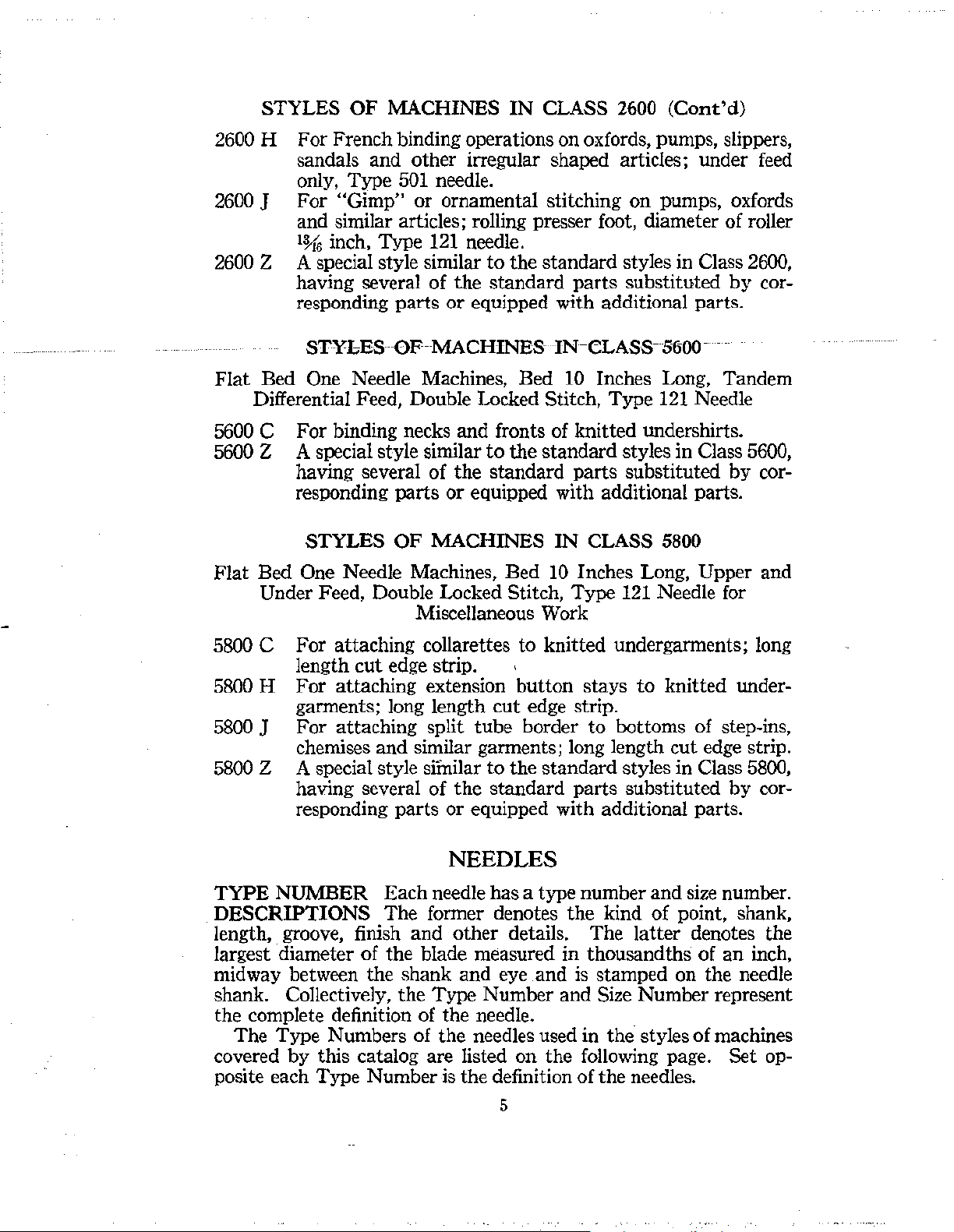
112
112 c
112 E
112
0112
112 cc
112
s
CN
Throat Plate,
Throat
Throat
Throat Plate, for Styles
Throat Plate,
Throat Plate,
Throat
Plate,
Plate,
Plate,
for
for
for
for
for
for
Styles
Styles
Style
Style
Style
Styles
1200
1700
2600
Throat Plate Screws No.
113
113 A
Frame Thread Guide, adjustable,
Classes
2300,
5800. . . . . . . . . . . . . . . . . . . . . . . . . . . . . . . . . . .
Frame Thread Guide, adjustable, 1 inch long,
1200
A,
1200 C, 1200 G,
1700
A,
1700
B,
1700
F, 1900 K, 5600
Frame Thread Guide Screw No.
Vl13
116
118
118
B
V118
134
137
138
P39A
141
t See page 7.
Tap, marked "Q2",
..;.,.
Wrench,
inch, for needle clamp
Thread Hook,
for
No. 86 A. . . . . . . . . . . . . . . . . . . . . . . . 12
for
looper threads. . . . . . . . . . . . . . . . . . . . . . . . .
Thread Tweezers. . . . . . . . . . . . . . . . . . . . . . . . . . . . . . . . . . . . . .
Tap, marked
Screw,
"X2",
for
cloth plate hinge cover latch. . . . . . . . . . . . . . . . . . .
for
plus size cloth plate screw No. 22521. 12
Needle Thread Controller Lever Eyelet,
2600J...........
...
.. . ....
Screw, for needle thread controller lever eyelet. . . . . . . . . . . . 9
Needle Thread Controller Lever Assembly,
2600
D,
2600
F,
2600
Needle Thread Controller Lever Screw. . . . . . . . . . . . . . . . . . . 9
to
the plates illustrating the parts Plate
knurled........................
for
looper thread on
wire,
for looper thread
2600,
5600,
5800; also Styles
0,
1200Q,
B,
2300
N,
C,
1200 G, 1200
2300M, 2300R, 2600H,
D,
2600
F,
5600,
5800.....................
1200
for
needle thread on
wire,
for
2300
P,
2300
for
0,
1200
for
2600
G.
for
styles in Classes
AA,
1200
AC,
needle thread
Q; also
needle thread
Q,
1200
AC,
2600J...
needle thread
. . . . . . . . . . . . .
98.
1200
A,
1200
C.
. . . . . . . . . . . . . . . . . 1
2300
B,
2300
M.
. . . . . . . . . . . . . . . . . 1
0.
1200
. . . . . . . . .
G,
1200
..
. . . . . . . . . . . . . . 1
Q..................
H. . . . . . . . . . . . . . . . . . . . . . . . . . 1
F.
. . . . . . . . . . . . . . . . . . . . . . . . . 1
2300
A,
2300
N..
. . . . . . . . . . . . . . . . 1
87.
2t
1200
0,
1200
inches long,
Q;
1200
for
AA,
styles in
for
Styles
1200
AC,
C................
22529.
nut.
. . . . . . . . . . . . . . . . . .
for
Styles 1700 H,
G,
...............
2600
H.......................
for
..........
Styles
2600
48
No.
11
13
12
14
14
for
14
14
14
13
1
24
24
20
20
20
10
13
A,
20
Page 51

Symbol
to
Order
by
The
figures in
and are
LIST OF PARTS
the
last column refer
not
to
be
used
in ordering. .
only
to
the
plates illustrating
the
parts
Plate
No.
148 A
150
154
156
161
181
A
187
188D
196
D
196
201C
202A
202 B
213
217
269
303
334
396 D
399
A
400
401
402
403
404
A
406 B
407 A
Throat
Throat
Plate
Needle Guard, hardened, for Styles 2600 A,
2600 D, 2600
Plate
Needle
F,
2600 G, 2600
Guard
H.......................
Screw No. 87.
11
Stop Screw, for cloth plate slides. . . . . . . . . . . . . . . . . . . . . . . . . 9
Needle Lever Buffer,
Needle Lever Ball,
wood
fibre. . . . . . . . . . . . . . . . . . . . . . . • . 12
hardened............................
10
Binding Holder Disc Supporting Collar, for Styles 5800 H,
5600]
...............................
Looper Rocker, hardened,
for
styles in Class 2300. . . . . . . . . 17
Screw, for binding guide adjustments . . . . . . . . . . . . . . . . . . . .
Set
Screw, knurled head, for roller
Throat
Throat
Throat
Screw, for toggle grinder
Needle
Needle
Needle
Plate
Needle Guard, hardened, for Styles 1700
1700 B, 2600
Plate
1700F
Plate
J.
. . . . . . . . . . . . . . . . . . . . . . . . . . . . . . . . . . . . .
Needle Guard, hardened, for Styles 1200 AC,
......
..
:.......
Needle
Guard
clamp..........................
Thread
1200
AC, 1700
Thread
Thread
1700
H.............................................
Pull-off
F,
Pull-off
and
1700
and
Take-up Wire, for Styles 1200 AC, 1700 F,
H.............................
Take-up Wire
support
.......
.....
Screw No. 87.
Take-up Wire Post, for Styles
,
... , ...........
swinging
........
Post
Screw No. 94.
arm
.........
16
9
. . . . 9
A,
11
11
10
13
13
Needle Thread Take-up Wire Screw No. 87 U.
Looper Rocker, hardened, for
1200
0,
1200 Q, 1700 A, 1700 B, 1700
Needle
2600
Thread
F,
Controller Rack, for Styles 2600
2600 G, 2600
Needle Thread Controller
Trimmer
styles in Class
Stand
Adjusting
2300. . . . . . . . . . . . . . . . . . . . . . . . . . . . . . . . . .
Screw, hexagon head, for
Tension
Tension
Welt Gauge Base, for
Welt Gauge Base
W e!t Gauge
Welt Gauge
Welt Gauge
Welt Gauge
Thread
Thread
Eyelet, with one eye, for Style 1900
Eyelet Screw No. 98.
Style 2600
Screws No. 25 CC.
Slide. . . . . . . . . . . . . . . . . . . . . . . . . . . . . . . . . . . . . . 19
Slide. Spring. . . . . . . . . . . . . . . . . . . . . . . . . . . . . . . 19
Slide Spring Screw. . . . . . . . . . . . . . . . . . . . . . . . . . 9
Slide Screw Pin, hardened; also for No. 410
Styles 1200 A, 1200 C, 1200 G,
H,
2600
J.
. . . . . . .
A,
2600 D,
H.
. . . . . . . . . . . . . . . . . . . . . . . . . . . . . 24
Rack
Rod
upper
Screws No.
Lock
feed
bar
D.
. . . . . . . . . . . . . . . . . . . . . 19
88.
Nut,
left thread, for
spring. . . . . . . . . . . . 9
K.
. . . 13
A..
25
11
10
Welt Gauge Slide Lever. . . . . . . . . . . . . . . . . . . . . . . . . . . . . . . . 19
Welt Gauge
Welt Gauge
Welt Gauge
Welt Gauge Slide Lever Stop
Welt Guide,
Welt Guide Screw; also for No.
Welt Guide
Slide Lever
Stud
No. 86.
Slide Lever Screw No. 97.
Slide Lever Stop
adjustable....
Plate.
. . . . . . . . . . . . . . . . . . . . . 19
Plate
Screws No. 94.
. . . . . . . . . . . . . . . . . . . . . . . . . . . . . 19
409
A...
. . . . . . . . . . . . . . . . . 9
Height Adjusting Screw No. 88.
49
Page 52

LIST OF PARTS
Symbol
to
Order
409 A
410 A
413
415
B
419 A
420
421
423
424
426
426
A
426 B
427
430
431 A
432
433
434
482
Y500-257
Y500-260
Y500-263
Y500-266
Y500-270
Y500-273
Y502-319
Y502-322
Y502-325
Y505-407
Y505-410
Y505-413
Y506-530
Y506-533
The
by
figures in the last column refer only
and are not
to
be used in ordering.
to
the
plates illustrating the parts Plate
Welt Guide Tongue, adjustable. . . . . . . . . . . . . . . . . . . . . . . . . 19
Welt Guide Tongue Screw No.
407.
A.
Flexible Guide . . . . . . . . . . . . . . . . . . . . . . . . . . . . . . . . . . . . . . . . 19
Flexible Guide Screw Pin No. 402.
Oil Can, with
Lifter Lever Casting,
Styles
1200 AD, 1700 F, 1700 H, 1900 K, 2300 N, 2300
1200
spout....
A,
. . . . . . . . . . . . . . . . . . . . . . . . . . . . . . . . 28
for
styles in Classes 2600, 5800; also
1200 C, 1200 G, 1200
AA,
1200
R......
Lifter Lever Extension. . . . . . . . . . . . . . . . . . . . . . . . . . . . . . . . . 20
Lifter Lever Extension Screws No. 93
Lifter Lever
Stud....
. . . . . . . . . . . . . . . . . . . . . . . . . . . . . . . . . . 10
A.
Lifter Lever Chain . . . . . . . . . . . . . . . . . . . . . . . . . . . . . . . . . . . . 20
Lifter Treadle Rest. . . . . . . . . . . . . . . . . . . . . . . . . . . . . . . . . . . .
Lifter Treadle Pin. . . . . . . . . . . . . . . . . . . . . . . . . . . . . . . . . . . . . 23
Lifter Treadle Pin Set Screw,
22813.
24
threads
to
inch, No.
Lifter Treadle Pin Set Screw, 32 threads to inch, No. 98,
obsolete.
Lifter Lever Spring. . . . . . . . . . . . . . . . . . . . . . . . . . . . . . . . . . . .
Lifter Lever Spring Pin . . . . . . . . . . . . . . . . . . . . . . . . . . . . . . . . 16
Lifter Lever Stop
Binding Holder Disc, 6 inches diameter,
Binding Holder
Pin
. . . . . . . . . . . . . . . . . . . . . . . . . . . . . . . . .
for
Style 5600
Axle,
for Styles
2600
H, 5600 C. . . . . . . . . .
C....
Binding Holder Spring Latch. . . . . . . . . . . . . . . . . . . . . . . . . . . 4
Binding Holder Tension Spring. . . . . . . . . . . . . . . . . . . . . . . . . . 14
Binding Holder Tension Nut, knurled . . . . . . . . . . . . . . . . . . . 10
Binding Holder Tension Lock
Collar,
Classes
1200
G.
for
floating design
1700, 2600, 5800; also Styles 1200
1200
0,
l200
Nut,
feed
Q, 1200
knurled. . . . . . . . . . . . . . .
rocker shaft on styles in
A,
1200 C,
AC,
1200 AD, 1900
K..
Collar Screw No. 98.
Expansion Reamer,
Expansion Reamer, size .260 inch
Expansion Reamer, size .263 inch
Expansion Reamer, size .266 inch
Expansion Reamer, size .270 inch
Expansion Reamer, size .273 inch
Expansion Reamer,
size .319 inch
Expansion Reamer, size .322 inch
Expansion
Reamer, size
Expansion Reamer,
for
needle bars, size
for
presser bars and presser guide bars,
.....................
.325
inch
for
feed
.257
inch. . . . . . . . . 26
.......................
.......................
.......................
.......................
.......................
: . . . . . . . . . . . . . . . . . 26
.......................
.......................
rocker shafts and
feed
shaft, size .407 inch. . . . . . . . . . . . . . . . . . . . . . . . . . . . . . . . . .
Expansion Reamer, size .410 inch
Expansion Reamer, size
.413 inch
.......................
.......................
Expansion Reamer, for main shafts, size .530 inch. . . . . . . . . 26
Exoansion Reamer, size
.533
inch
.......................
AC,
. . .
bar
No.
20
24
14
24
29
11
11
24
.
.
.
.
.
.
.
26
.
.
.
50
Page 53

LIST OF PARTS
Symbol
to
Order
Y510-200
531
539
540
605
605A
0650-10
0650-24
0660-31
Y800
Y801
Y802
900
901
902
The figures in the last column refer only
and
are
by
not to be
used
in ordering. No.
Expansion Reamer, for needle bars, size .200 inch. . . . . . . . .
Screw, for toggle grinder emery wheel guard, left. . . . . . . . . . 9
Frame
Frame
Frame
Thread Eyelet, adjustable, for Styles 1200 AD, 1700 G.
Thread Eyelet Screw No. 94.
Thread Eyelet Guide
Screw, for presser foot spring on Style 1900
Screw, for needle
bar
thread guide, on Style 1200 A. . . . . . . . 9
Stove Bolt, flat head, l x
hanger, rear
Stove Bolt, flat head,
Ball,
.0625 inch diameter, for rolling presser foot.
.......................................
l x 3 inches
Taper Reamer, for lever end of needle lever
Taper
Taper
Cloth
Reamer, for frame end of needle lever
Reamer, for needle lever link pins
link
pin............................................
Plate
Slide, right, fpr Style 2600
Cloth Plate Slide, right, for Style 2600
Feed Rocker, non-floating desigu, for Styles 2600
5800 C, 5800 H, 5800
J. . ..
to
the
plates illustrating the parts Plate
Pin.
. . . . . . . . . . . . . . . . . . . . . . .
K..
. . . . . . . . . . . 9
1l
inches, for knee lifter shaft
.
......................
stud
stud
and
A.
. . . . . . . . . . . . . . . .
D..
. . . . . . . . . . . . . . .
.......
.........
........
feed crank
A,
2600 D,
.
: .
.
.
. . . . . . . . . . . . . . . . . . . . . . . . . . . 28
26
24
16
26
21
21
Feed Rocker Screws No. 88.
903
904
;)05
906
906 A
907
908
911
•
912
Feed Bar, for under feed, in Styles 2600
5800 H, 5800
Feed
Bar
Feed
Bar, for upper feed, in Styles 2600
5800
H,
Upper Feed
5800 H, 5800 J
Upper Feed
J......................................
Screws No. 88.
5800
J......................................
Bar
Spring, for Styles 2600
...............................
Bar
Spring Screw No. 303.
Adjusting Screw, hexagon head, for upper feed
Styles
Adjusting
Styles
2600
Scre'W,
2600
A,
2600 D, 5800 C, 5800 H, 5800 J.. . . . . . . . . 9
hexagon head, for upper feed dog on
A,
2600 D.. . . . . . . . . . . . . . . . . . . . . . . . . . . . . . . 9
Upper Feed Dog Adjusting Screw Lock
906
.........................
Feed
Bar
Prong
5800 C, 5800
Feed
Bar
Prong Screws No. 94.
Upper Feed Dog, for Styles
Upper Feed Dog Screw No.
and
H,
Sponge, for Styles 2600
5800 ] ..
............................
36oo
A,
f'~A.
Upper Feed Dog Holder, for Styles
Upper Feed Dog Holder Screws No. 93
917
Feed Lift Eccentric, ground, for Styles 2600
5800 C, 5800 H, 5800 J
..............................
A,
2600 D, 5800 C,
A,
2600 D, 5800 C,
A,
2600 D, 5800
bar
Nut;
also for No.
:......................
A,
2600 D
l,l600
..............
A,
2600 D
A.
A,
C,
; . . . . . .
spring, in
2600 D,
.......
2600 D,
22
22
20
11
.
24
.
6
.
15
.
24
Feed Lift Eccentric Screw No. 96.
918
919
0
Seepage7.
Presser Foot, for Style
Presser Foot, for Style
Presser
Foot
Clamp Screw No. 91.
2600 A
2600 D
......... , ................
..........................
7
.
7
.
51
Page 54

LIST OF PARTS
Symbol
to
Order
920
1000
1002
1003
1004
1005
1007
1008
1054
1059
1096
1201
AC
1205 c
1215 A
1216
B
1216
c
1220
AA
1220
AC
1221
The
figures
by
in the last column refer only
and are not
Main
to
be used in ordering.
Shaft Sleeve, left, ! inch long, for Styles 2600
2600 D, 5800 C, 5800 H, 5800 J
to
the plates illustrating the
......................
Thread Lubricator Assembly, for Styles 2600
2600 F, 2600 G, 2600 H
Thread Lubricator Cup
Thread
Lubrica~or
Thread Lubricator
.......
.
Thread Lubricator Bracket
Cup
Cup
.............................
...............................
Pin
............................
Felt
...........................
............................
Thread Lubricator Bracket Screw No. 95.
Thread Lubricator Tension
Thread Lubricator Tension
Thread Lubricator Tension
Thread Lubricator Tension Spring No.
Plate
.......................
Post
No. 1346.
Post
Ferrule No. 1347.
110-2.
Thread Lubricator Tension Spring Ferrule No. 107.
Thread Lubricator Tension Regulating
Thread Lubricator Tension Felt, lower
Looper Eccentric, ground, for Styles
Nut
No. 108.
..................
2600
H,
Looper Eccentric Screw No. 96.
Screw, for adjusting yielding guide on Style
Adjusting Screw, for loop retainer in Style
Cloth Plate, for Style 1200 AC
Plate
Cloth
Screws No. 80.
Main Feed Dog, for Style 1200 AA
Main
Feed Dog Screw No. 22593.
Needle Lever, for Styles in Classes
1200
A,
1200 C, 1200 G, 1200
1700
A,
1700 B, 1700 F, 1700 H, 2600 J
.........................
.....................
5600, 5800; also Styles
0,
1200
1700 A
1900
Q,
1200
...............
Needle Lever Connecting Rod Assembly, wick feed oiling;
one each Nos.
15430 D, 15430 M, 22586 A
Needle
Lever Connecting Rod Assembly, wick
feed oiling; one each Nos.
1230 G, 15430 C, 15430 D, 22586
Presser Foot, for Style
Presser Foot, for Style
Presser
Foot
1230
A,
1230 B, 1230 C, 1230 D, 15430 C,
.........................
1230
1200 AA
1200 AC
........
........................
Clamp Screw No. 91.
A,
1230
B,
1230 C, 1230 D,
A,
and two No. 41046 G.
."
...............
Eccentric Pulley, throw .529 inch, for Styles
2300, 5600, 5800; also Styles 1200
12000,
1200Q,1200AA,1700A, 1700B,1700
A,
1200 C, 1200 G,
Eccentric Pulley Screws No. 22597.
A,
2600 D,
5800 J
.......
K.
.......
AA,
1200 AC,
and
in
H,
2600]
parts
A,
.....
splash
Classes
..
Plate
No.
.
16
.
17
.
17
.
.
17
.
17
.
12
12
.
.
16
.
9
9
.
.
29
.
5
.
28
.
17
17
.
7
.
7
18
1228 A
t1230 A
Throat
Throat
Pl~te,
for Style 1200
Plate
Screws No. 87.
AD
Needle,Lever Connecting Rod
Needle Lever Connecting Rod
.......................
Upper Bearing
Upper Bearing Screws No.
22587.
1230 B
t
Seepage
Needle Lever Connecting Rod
7.
Upper Bearing Valve spring
52
............
..
.
1
.
17
14
Page 55

LIST OF PARTS
. '
Symbol
to
Order
----
1230
c
1230
D
tl230G
1248
1261
1275 A
1275
E
1275
F
1275
H
1275
J
:;:Seepage
The
by
figures in the last column refer only
and are not
to
be used in ordering. No.
to
the plates illustrating the parts Plate
------------------------1---
Needle Lever Connecting Rod Tube
Needle Lever Connecting Rod Tube Nut, left thread, No.
15430
c.
Needle Lever Connecting Rod Tube
No. 15430 D.
Needle Lever Connecting Rod
Needle Lever Connecting Rod
No. 22586A.
Needle Lever Connecting Rod Lower Bearing, splash
oiling,
5800
for
styles in Classes
..............................................
Needle Lever Connecting Rod Lower Bearing Screws
No.
22587.
Feed Crank Link Shim,
leather..........................
Looper Rocker Frame, without cone. . . . . . . . . . . . . . . . . . . . .
Looper Rocker Frame Screw, left, No.
Looper Rocker Frame Screw, right, No. 98.
Looper Rocker Frame Spot Screw No.
Needle Lever Stud, standard diameter
Needle Lever Stud, plus size on frame section, viz.: .001,
.012,
.002, .003, .006,
Example:
on
frame section
1275
E-003 represents a stud plus
....................................
.018
Needle Lever Stud, plus size on
.002, .003, .006 inch; specify plus amount. Example:
1275
F-003 represents a stud plus .003 inch on
section
............................................
Needle Lever Stud, plus size equal on
.001, .002,
1275
section
.003,
.006 inch; specify plus amount. Example:
F-003,represents a stud plus
............................................
Needle Lever Stud, plus size unequal on each section, viz.:
(.001,
(.002,
(.003,
(.012,
(.018,
.002)
.003)
.006)
.001)
.001)
(.001,
(.002,
(.006,
(.012,
(.018,
.003)
.006)
.001)
.002)
.002)
Specify plus amounts, arranged frame section first and
section last. Example: 1275 J-003--006 represents a
stud plus
lever
inch on
.003
section,
frame
inch on frame section and .006 inch on
1275
J-006--003 represents a stud plus
section and .003 inch
Needle Lever Stud Screw No.
Needle Lever Stud Felt No. 15430 L. Note: Belore lap-
ping the bearing of a needle lever and a needle lever stud
remove the felt from the stud
lapping compound has been washed out.
7.
53
.......•.............
Nut,
Upper Bearing Valve
Upper Bearing Valve Screw
1200,
1700,
2300, 2600,
88.
96.
............
inch; specify plus amount.
lever
section, viz.: .001,
each
.003
(.001,
(.003,
(.006,
(.012,
(.018,
.006)
.001)
.002)
.003)
.003)
on
lever
22586.
and
replace
right thread,
......
feed
5600,
; . . . . . .
.003
inch
lever
section; viz.:
inch on
(.002,
(.003,
(.006,
(.012,
(.018,
each
.001)
.002)
.003)
.006)
.006)
lever
.006
section
.....
it
after the
17
.
16
.
17
12
22
20
.
.
.
.
Page 56

Symbol
to
Order
by
LIST OF PARTS
The
figures in the last column refer only
and are not
to
be used in ordering.
to
the plates illustrating the parts Plate
No.
1280
1286
1286
A
Needle Lever Ball Clamp Bolt
Needle Lever Link Pin Assembly, internal oiling, hardened
and
ground, one each Nos. 1286
22560; also
for
No.
15446
Needle Lever Link Pin. . . . . . . •. . . . . . . . . . . . . . . . . . . . . . . . .
Needle Lever Link Pin Set Screw, upper, No.
Needle Lever Link Pin Set Screw, lower, No.
Nut,
also for No.
A,
1286 B, 12964 C,
D.. . . . . . . . . . . . . . . . . . . . . . . . . . 16
77.
78.
Needle Lever Link Pin Ball No. 12964 C.
1286 B
1287
1288
1346
1347
1349
1361
A
1362
1520
M-13
Needle Lever Link Pin Spring
Needle Lever Link
Needle
Bar
inch needle
Pin
Thread Nipper Assembly, for use with
bars.....................................
Needle Bar Thread Nipper Collar. . . . . . . . . .
Needle Bar Thread Nipper Collar Screw No.
Tension Post, length overall
ened steelferrule. . . . .
Tension
Tension
Presser Spring
Main Shaft Sleeve
Post
Ferrule, hardened. . . . . . . . . . . . . . . . . . . . . . . . . 16
Spring, .036 inch diameter wire,
on styles in Classes
also for No.
23285
5600,
A-!.
Pin.....................................
Pin.
Rolling Presser Foot Assembly, diameter of roller
........
Spring Screw' No.
'.
. . . . . . . . . . . . . . . . . .
22560.
..
88.
1ft
inches,
..
.. ..
. . . .
5800 and Styles
23285
A-i.
.. ..
23285
for
use with
..
. .
..
for
needle threads,
1200
A-!.
. . . . . . . . . . . . . . . . . . . . . . . . . . . . . . . .
ball bearing design, universal adjustment, for Style
1520
M-21
2600].....
Rolling Presser
............
Foot
Assembly, diameter of roller
.........
......
..
ball bearing design, universal adjustment, for Style
2600
G.............................................
1580
G-13 Roller, ball bearing design,
for
Style
2600
J
.....................................
1580
G-21 Roller,
1584
Roller
Roller
Roller Support, adjustable
11"~
inches diameter,
Axle
Screw No.
Axle
Lock Screw No.
Roller Support, Set Screw, hexagon head, No.
1592
B Roller Support Swinging Arm, adjustable
Roller Support Swinging Arm Set
H·
inch diameter, -h inch
1\
inch
face,
22818.
227
43.
..............................
Screw, knurled head,
for Style
22519.
................
No.188 D.
Roller Support Swinging Arm Stop Screw No.
Roller Support Swinging Arm Hinge Pin No.
1592
C Roller Support Swinging Arm Bracket, lower, adjustable
22575.
1594
Roller Support Swinging Arm Bracket Screw No.
1593 C Roller Support Swinging Arm Bracket, upper
............
Roller Support Swinging Arm Bracket Set Screws No.
1593
E Roller Support Swinging Arm Bracket, intermediate, ad-
justable
...........................................
Roller Support Swinging Arm Bracket Screw No.
15745
B.. .
.257
. . . . . . . . . . .
hard-'
.. ..
. . .
.. ..
AA,
1700
A;
. . . . . . . . .
Hinch
.......
....
11"~
inches,
face,
2600
G.
A.
...
22548.
22584.
22548.
11
16
14
13
13
11
14
16
16
8
8
.
.
.
.
.
54
Page 57

LIST OF PARTS
Symbol
to
Order
1594
A
1701
E
1702
1704
1705
1707
G
1708
G
1715
1720 B
1721
1724 A
1724
F
1727
A
1727 D
1728
1728 D
1731
1741
B
1742
1749
1755
1825
1825 A
1859
1901
D
The figures in the last column refer
by
and are not
to
be used in ordering. ·
Roller Support Swinging Arm Hinge
Cloth
Plate,
for
Style
Cloth Plate Screws No.
Cloth Plate Slide, right, for Style 1700
Cast-off Wire, for Styles 1200 AC, 1700 F,
1700
80.
only
to
the plates illustrating the parts
Pin
................
G.
. . . . . . . . . . . . . . . . . . . . . . . . . .
G.
. . . . . . . . . . . . . .
1700
H....
Cast-off Wire Screw No. 22521.
Feed Dog, for Style 1700 G.. . . . . . . . . . . . . . . . . . . . . . . . . . . . 5
Feed Dog Screw No.
Looper, with guard, for Styles 1200 AD, 1700
Looper, without guard, otherwise same as No.
Looper Set Screw No.
Needle Lever, for Styles 1200 AD,
Presser Foot,
Presser
for
Foot
Clamp Screw No. 91.
Eccentric Pulley, throw
1700
G.............................................
Eccentric Pulley Screws No.
Throat Plate, for Style 1700
Throat Plate, for Style 1700
Throat
Plate.Screws No. 87.
Presser Foot, for Styles
Presser Foot,
Presser
Throat
for
Foot
Clamp Screw No.
Plate, for Style
Throat Plate, for Style 1700
Throat Plate Yielding Guide No.
Throat Plate Yielding Guide Screw No.
Throat
Throat
Plate Yielding Guide Adjusting Screw No.
Plate Screws No.
Presser Spring,
Presser Foot Chain Knife,
Presser
Throat
Foot
Chain Knife Screw No. 187
Plate Yielding Guide,
Tension Spring,
on Styles
1200
Hand Lifter, hardened, for Style
Hand Lifter Stud No.
Feed Bar Needle Rear Guard, hardened, for Style
Feed
Bar
Needle Rear Guard Screw No.
Needle Rear Guard, for Style 1200
93.
73.
Style
1700
G.
. . . . . . .
.389
inch, for Styles 1200 AD,
22597.
G. . ..
F.
1700
F, 1700
Style 1700 A. . . . .
91.
1700
B.
A..
87.
fgr
Styles 1200 AD,
for
Styles
for
.040
inch diameter wire,
AD,
1700
G.
. . . . . . . . . . . . . . . . . . . . . . . . . . 14
86.
G...........
1707 G .....
1700
G................
.. . ..
. . . . . . . . . . . . . 7
. . . . . . .
..
. . . . . . . . . . . . . 3
. . . . . . . . . . . . . . . . . . . . . . . . . 3
H..................
.. ..
. . . . . . . . . . . . . . . . . 7
. . .
..
. . . . . . . . . . . . . . . . . . . 2
. . . . . . . . .
..
. . . . . . . . . . . . . 2
1742.
73
A.
1059.
1700
G.
. . . . . . . . . . . . . . 19
1700
F, 1700
H.......
A.
Style
1700
A.. . . . . . . . . . . . 16
for
needle threads
17P<l
G..................
1900
94.
AD...................
Needle Rear Guard Clamp Screws No. 79.
Needle Guard Stand. . . . . . . . . . . . . . . . . . . . . . . . . . . . . . . . . . .
Needle Guard Stand Screws No.
Cloth Plate,
Cloth Plate Screws No.
for
Style 1900
80.
K.
22596.
. . .
..
. . . .
..
. . . . . . . . . . . . . . .
. . . .
K.
Plate
No.
.
29
21
13
8
.
28
18
7
12
18
11
12
20
29
55
Page 58

LIST OF PARTS
Symbol
to
Order
1903
.T
1903
K
1905 J
1905 L
1908 A
L
1911
1917 K
1920 J
1920 K
1922 D
1924
J
1924 L
The figures
by
and are not
Swing Gauge Assembly, attaches
1900
in
the last column refer only
to
be
used in ordering.
to
the plates illusrtating the parts Plate
to
cloth plate, for Style
K.............................................
Edge Guide No. 1931 C.
Edge Guide Thumbscrew No. 22756.
Edge
Guiae Swinging Arm No.
Edge Guide Swinging Arm
Edge Guide Swinging Arm
No. 12957
E.
Pivot
Pivot
1931
Stud
A.
No. 22726.
Stud
Spring Washer
Edge Guide Swinging Arm Base No. 1931 B.
Swing Gauge Assembly Screws No. 22514.
Swing Gauge Assembly Screw Washers No. 9255.
Swing Gauge Assembly, attaches
Style
1900 K
.......................................
to
cloth plate slide, for
Edge Guide No. 1931.
Edge Guide Thumbscrew No. 22756.
Edge Guide Swinging
Edge Guide Swinging Arm
Edge Guide Swinging
Arm No.
Pivot
Arm
1931
Stud
Pivot
A.
No. 22726.
Stud
Spring Washer
No.12957E.
Edge Guide Swinging Arm Base No. 1931 B.
Swing Gauge Assembly Screws No. 25
S.
Swing Gauge Assembly Screw Washers No. 9255.
Feed Dog, for Style
Feed Dog, for
plate slide
.........................................
Feed Dog Screw No. 93
Looper, for Style 1900
1900
K.. . .. . ..
..
.. .. . .. . .. .. ..
Style 1900 K, with gauge attached
A.
K..
. . . .
..
. . .
..
. .
.. . ..
Looper Set Screw No. 73.
Loop Retainer, for use with
Needle Bar,
Needle
hard~ned
Bar
Set
Screws No.
and
Presser Foot, for Style 1900
Presser
Presser
Presser
Foot
Set
Screws No. 22570.
Foot
Spring No. 6533.
Foot
Spring Screw No. 605.
throat
ground, for Style 1900
88
K.
plate No. 1924 L
A.
. . . . . . . . . . . . . . . . . . . . . . . . . 7
Presser Foot, for Style 1900 K, with gauge attached
cloth plate slide
Presser
Main
Throat
Throat
Throat
Throat
Throat
Throat
Foot
Shaft, hardened
Plate, for Style 1900 K. . . .
Plate
Plate
Plate
Plate
Plate, for Style 1900 K, with gauge attached
cloth plate slide
Throat
Plate
....................................
Set Screws No. 88.
and
ground, for Style 1900
..
. . . . . .
Screws No. 87.
Loop Retainer No.
27
X.
Loop Retainer Screw No. 87 U.
Loop Retainer Adjusting Screw No. 1096.
...................................
Screws No. 87.
..
.. ..
. .
to
cloth
..
.. . .. ..
......
K.
. . . . . .
K.
. . . . . . 25
.. ..
. . .
.
..
. 5
.
. 8
.
to
.
..
. 3
to
..
No.
19
23
56
Page 59

LIST OF PARTS
Symbol The
to
Order
by
1931
A
1931
1931 B
1931 c
1935
1937
1939
1940
1941
t 1955 M
2305 p
2305 R
2306
2315 A
2320 R
2324 p
2324 Q
R
2324
2326 A
2326 p
2326 R
2331
figures
and are not
Edge Guide, for Style 1900
cloth plate slide
in the last column refer only to the plates illustrating the parts Plate
to
be used in ordering.
K,
with gauge
attached
to
....................................
Edge Guide Thumbscrew No. 22756.
Eclge Guide Swinging Arm, for Style 1900
Edge Guide Swinging Arm
Edge Guide
12957
Swinging Arm
E.
Edge Guide Swinging
Edge Guide, adjustable
Edge Guide Thumbscrew
Feed
Rocker, non-floating design, for Style 1900
Feed
Bar
Prong
and
Feed
Bar
Prong Screws No. 94.
Feed
Feed
Feed
Feed
Feed
Feed
Feed
Feed
Feed
Crank
Crank
Crank
Crank
Crank
Crank
Bar
Bar
Link, hardened, for
Link Shim, No. 1248.
Link Screw, H inch long, No. 22569.
Link Lock
Crank
Link Screw,
Stud
Cap, for Style 1900
Stud
Cap
Shoe, for Style 1900
Shoe Screw No. 94.
Needle Lever Connecting
oiling, for
Style 1900
Pivot
Stud
Pivot
Stud
Arm
Base
...
, , ,
...............................
No.
22756.
Sponge, for Style 1900
Style
Nut
No. 7947.
it
inch long, No. 79, obsolete.
Screws No. 77.
K..
. . . . . . . . . . . . . . . . . . . . . .
Rod
Lower Bearing, splash feed
K.
.............................
K.
............
No. 22726.
Spring Washer No.
.... , .............
K.
. . . . . . . 28
K..
. . . . . . . . . . .
1900
K.
. . . . . . . . . . . . 15
K..
. . . . . . . . . . . . . . . .
Needle Lever Connecting Rod Lower Bearing Screws No.
22587.
Main
Feed
Dog, for Styles 2300 P, 2300
Main
Feed Dog, for Style 2300
Main
Feed Dog Screw No. 90.
Feed
Lift
Eccentric, ground, for Styles 2300
2300 R.
I<eed
....
~.......................................
Lift Eccentric Screw No. 95.
Needle Lever, for styles in Class
Presser Foot, for Style 2300
Presser
Throat
Throat
Throat
Throat
Feed Dog, for
Feed
Foot
Clamp Screw No. 91.
Plate, for Style 2300
Plate, for Style 2300
Plate, for Style 2300
Plate
Screws No. 87.
Style 2300
Dog Screw No.
93
Differential Feed Dog, for
Differential Feed Dog, for
Differential Feed Dog
Feed Rocker, for
Styles 2300
R.
P.
Q.
R.
M.
. . . . . . . . . . . . . . . . . . . . . . . . . . . 5
A.
Styles 2300
Style 2300
Screw No. 22585.
P,
R..
2300 . . . . . . . . . . . . . . . . . . . .
. . . . . . . . . . . . . . . . . . . . . . . . . 7
. . . . . . . . . . . . . . . . . . . . . . . . . 2
. . . . . . . . . . . . . . . . . . . . . . . . . 2
. . . . . . . . . . . . . . . . . . . . . . . . . 2
2300 Q, 2300
Q.
. . . . . . . . . . . . . . 6
. . . . . . . . . . . . . . . . . . . . . 6
P,
2300 Q,
P,
2300
Q.
. . . . . . . . . 5
R.
. . . . . . . . . . . . . . . • . 5
R.
. . . . . . . . . .
Feed Rocker Screws No. 88.
No.
.
.
.
.
24
24
24
.
24
28
27
~Seepage
7.
57
Page 60

LIST OF PARTS
Symbol
to
Order
by
2332
2333
2334
2335
2336
2338
2340
2341
2343
234.~
A
2345
2349
A
2349
2355
2366
B
2366
c
2366
D
2366
E
2366
F
2366 G
2373
2375
A
2389
B
2390
2392
The
figures in the last column refer only
and are
not
to
be used in ordering.
Feed Bar,
for
Styles
2300
P, 2300 Q,
to
the plates illustrating
2300 R .............
the
parts
Feed Bar Screws No. 88.
for
Feed Bar Prong and Sponge
2300
R.
...........................................
Feed
Bar
Prong Screws No. 94.
Differential Feed Bar Link, for Styles
2300
R.
...........................................
Differential Feed Bar
Link
Screw No.
Differential Feed Bar, for Styles
Differential Feed Bar Guide
...........................
Differential Feed Bar Guide Screws No.
Main Shaft Sleeve, left,
2300
Q,
2300 R ....................................
1t
Styles 2300 P,
97.
2300
P, 2300 Q,
inches long
2300
93
for
A.
Trimmer Bracket Arm Connection, for styles in Class
2300
P, 2300 Q,
2300 R ...
Styles
2300
2300
Q,
P,
..
Trimmer Bracket Arm Connection Screws No. 94.
Upper Toggle, ! inch blade, sides beveled equal, minimum
width of seam
Upper Toggle,
rt
inch, for styles in Class
for
Styles
2300
M,
2300
.........
2300 R ................
Upper Toggle, i inch blade, two teeth, double cutting
edges, minimum width
Class
2300
.........................................
of
seam ! inch, for styles in
Upper Toggle, ! inch blade, beveled both sides, minimum
width of seam ! inch
Upper Toggle,
1!
minimum width of seam ! inch
Upper Toggle,
! inch
...............
1!
...................
,
...........
inch blade, fiat surface in front of notch,
.............
: .
.......
inch blade, minimum width of seam
,
............................
Upper Toggle Screw No. T22.
Lower Toggle, i inch blade, for styles in Class
2300
......
Lower Toggle Screw No. T12.
Trimmer Pitman Assembly, for Styles
2300
M,
2300
N;
one each Nos.
two No. 87
U
.....................................
Trimmer Pitman, front section, for assembly No.
Trimmer Pitman, rear section, for assembly No.
87
Trimmer Pitman Screws No.
U.
Trimmer Pitman Assembly, for Styles
2300
R;
one each Nos.
2366
F,
2366
Trimmer Pitman, front section, for assembly No. 2366 E
Trimmer Pitman, rear section, for assembly No.
2300
A,
2300
2366
C, 2366 D and
2366 B ..
2366
B.
...
2300
P,
2300
G and. two No. 87 U
...
2366
E
...
B,
Q,
..
Trimmer Pitman Screws No. 87 U.
Rivet Pin, for trimmer bracket and stand assembly
Toggle Grinder Assembly
..............................
Looper Thread Pull-off Wire, for styles in Class
Looper Thread Pull-off Frame
Frame Chain Knife,
for
Frame Chain Knife Screw No.
.........................
Style
2300 N ...................
25
CC.
.......
2300
.....
Plate
No
.
22
.
24
.
15
.
20
.
15
.
16
12
.
4
.
4
.
4
.
4
.
4
.
4
.
4
.
15
.
.
15
.
.
.
.
30
.
13
.
13
.
41
58
Page 61

LIST OF PARTS
Symbol
to
Order
--~--
2394
2395
2396
2397
A
2397
2397 B
~2398
2501
J
2503
J
2505 A
2505
B
2515
A
2524 B
2524 J
2527
D
2601
2603 D
2605 A
2624 A
2650
4517
4937
5002 J
5002 L
5005 H
5005
p
The
by
figures in the last column refer only
and
·are
not
to
be used in ordering.
to
the plates illustrating
the
--------------------------
Trimmer Clamp Screw, for styles in Class 2300. . . . . . . . . . . .
Trimmer Clamp Lever. . . . . . . . . . . . . . . . . . . . . . . . . . . . . . . . .
Trimmer Clamp Lever Screw No. 22572.
Trimmer
Trimmer
Trimmer
Trimmer
Trimmer Stand Adjustment Indicator Support. . . . . . . . . . . . 3
Trimmer
22517.
Cloth
Cloth Plate Screws No. 80.
Gauge, for Style 2600 H. . . . . . . . . . . . . . . . . . . . . . . . . . . . . . . .
Gauge Screw No.
Feed Dog,
Feed Dog, for
Feed Dog
Needle Lever,
2600
Throat Plate, for Style 2600
Throat
Throat
Presser Foot, for Style 2600
Presser
Cloth Plate, for Styles 2600
Cloth Plate Screws No. 80.
Welt Gauge Assembly, for Style 2600
Under Feed Dog, for Styles 2600
Under Feed Dog
Throat
Throat
Upper Feed Dog Lifter, for Styles
5800
Upper Feed Dog Lifter Screw No. 98.
Needle Bar, hardened and ground, for
Needle
Differential Feed
2300
Cloth Plate Hinged Cover, for Styles 5800 C, 5800
5800
Cloth Plate Hinged Cover, for Styles 1200 AA. . . . . . . . . . . .
Cloth Plate Hinged Cover Screws No.
Under Feed Dog, for Styles
Under Feed Dog
Upper Feed Dog, for Style 5800
Upper Feed Dog
Stand Regulating Rod, for styles in Class 2300. . . .
Stand
Adjustment Indicator. . . . . . . . . . . . . . . . . . . .
Stand
Adjustment Indicator Lock
Stand
Adjustment Indicator Lock
Nut.
Nut
Cover.. . . .
. . . . . . . . .
Stand Adjustment Indicator Support Screw No.
Plate, for Style 2600 H . . . . . . . . . . . . . . . . . . . . . . . . . . .
25
S.
ten
teeth to inch, otherwise same as No. 22
Style 2600 G. . . . . . . . . . . . . . . . . . . . . . . . . . . . . 5
Screw No. 93.
for
Styles 1900 K, 2600
G,
2600
H.
. . . . . . . . . . . . . . . . . . . . . . . . . . . . . . . . . . . .
Plate, for Style 2600
G.
. . . . . . . . . . . . . . . . . . . . . . . . . 2
H.
. . . . . . . . . . . . . . . . . . . . . . . . . 2
A,
2600
D, 2600 F,
Plate Screws No. 87.
H.
. . . . . . . . . . . . . . . . . . . . . . . . . 7
Foot
Clamp Screw No.
Screw No.
Plate, for Styles 2600
A,
93.
A,
91.
2600
A,
2600
D.
. . . . . . . . . . . . . . . . . .
D..
. . . . . . . . . . . . . . . .
2600
D..............
D.
. . . . . . . . . . . . . . . . . 2
Plate Screws No. 87.
2600
A,
2600
D, 5800 C,
H,
5800 J. . . . . . . . . . . . . . . .
..
. . . . . . . . . . . . . . . . . . . . .
Style 1200 A. . . . . . . .
Bar
Set Screws No. 88.
Bar
Link Stud, front, for Styles 2300 P,
Q, 2300
].
R.....................................
. . . . . . . . . . . . . . . . . . . . . . . . . . . . . . . . . . . . . . . . . . . .
25
CC.
5800
C,
5800
H.
. . . . . . . . . . . . . 5
Screw No.
Screw No. 87
93.
C.
. . . . . . . . . . . . . . . . . . . . . 6
U.
·
parts Plate
No.
D...
28
H,
10
20
23
11
11
11
29
12
5
29
19
5
20
23
10
21
21
t See
page
7.
59
Page 62

Symbol
to
Order
by
The
figures in
and are
LIST OF PARTS
the
last column refer
not
to
be
used in ordering.
only
to
the
plates illustrating
the
parts
Plate
No.
5045
5125
5142
5143
5144
5150
5156
5157
5449
t5601 c
5605 D
5620 c
5624 c
5626
5650
5723
t5801 c
5805 X
5807
Upper Feed Dog Holder Arm, for Styles 5800 C, 5800
5800 J
............................................
Upper Feed Dog Holder Arm Screw No. 93 A.
Feed
Bar
Needle. Rear Guard, for Style 1200 A
Feed
Bar
Needle Rear
Feed Bar, for Styles
Feed
Bar
Screws No. 88.
Differential Feed
Differential
Main
Main
Feed
Feed Dog Holder, for Style 1200 AA
Feed
Dog Holder Screw No. 93.
Guard
1200
Screw No. 94.
A,
1700
H,
1900 K, 2800.]
B1lt",Jor Styles 1200 AA, 5600 C
Bar
Link
Stud
Nut.
. . . . . . . . . . .
Feed Rocker, non-floating design, for Styles
5600 c
Feed
............................................
Rocker Screws No. 88.
Feed Rocker Arm, for use with feed rocker
..........
........
..............
1200 AA,
No.
5156
......
......
Feed Rocker Arm Screws No. 22548.
Looper Connecting Rod,
1200 G, 1200
1700 B, 1700
Cloth
Plate
Cloth
Plate
Main
Feed Dog, for Styles 5600 D
Main
Feed
· Presser Foot, for
Presser
Throat
Throat
Foot
Plate, for Style 5600 C
Plate
0,
F,
Assembly, for Style 5600 C
Screws No. 80.
Dog Screws No. 22593.
Style
Clamp
Screws No. 87.
Differential Feed Dog, for Styles
6flf
inches long, for Styles 1200 C.
1200 Q, 1200 AA, 1200 AC, 1700 A,
1700
H,
2600 ], 5600 C
...............
.................
.....................
5600 C
.........................
Screw No. 91.
.........................
1200 AA, 5600 C
.......••
Differential Feed Dog Screw No. 22585.
Main
Feed Dog Holder, for Style 5600 C
Main
Feed Dog Holder Screw No. 93.
Looper
Looper
Cloth
Cloth
Upper
Thread
1700
F,
1700 G, 1700 H
Thread
Plate
5800 J
Plate
Take-up Screw No. 89.
Assembly, tor Styles 1200
.................••..........................
Screws No. 80.
Feed Dog, 16 teeth
Take-up, for Styles 1200 AC, 1200 AD,
.............................
perform welt seaming operations
to
inch, for Style 5800 Z,
................
AA,
5800 C, 5800
on
automobile work
Upper Feed Dog Screws No. 87 U.
Looper,
Style
with
guard, for styles
,1200 AA
in
Classes 5600, 5800; also
.....................................
.....
....
H,
. .
H,
to
.
6
.
11
25
.
22
.
11
.
15
27
.
.
22
.
23
.
29
.
5
.
7
1
.
5
.
15
.
3
29
6
.
8
5813
5820 c
1:See
page 7.
Looper Rocker, hardened, for styles in Classes 5600, 5800;
also Style
Presser Foot. for Style
1200 AA
.................................
5800 C
..........................
60
.
17
.
8
Page 63

Symbol
to
Order
by
The
figures
and are not
LIST OF PARTS
in the last column refer only
to
be used in ordering.
to
the plates illustrating the parts
Plate
No.
5820 J
5824 c
5824 J
5826
B
5826
5826 c
5826 D
5827 A
5827 B
5828 A
5842 A
6042
6207 B
6208 B
6402 F
6440
6502 p
65:r.l
7421
7638 A
8645
8646
8647
Presser Foot, with groove, for Style 5800
welt seaming operations
Presser
Throat
Throat
Throat
Under
Foot
Clamp Screw No. 91.
Plate, for Styles 5800 C, 5800 H
Plate, for Style 5800 J
Plate
Screw No. 87.
Feed
Dog, for Style 5800 Z,
operations on automobile work
on
automobile work
..........................
to
perform welt seaming
.............
Z,
to
...........
........•.........
~
..........
Under Feed Dog Screw No. 93.
Upper Feed Dog, for Style
Upper
Under
Feed
Dog Screws No. 87 U.
Feed
Dog, for Style 5800 J
5800 H
......................
......................
Under Feed Dog Screw No. 93.
Upper
Feed
Dog,
for
Style 5800 J
......................
Upper Feed Dog Screws No. 87 U.
Presser Foot, for Style 5800 H
Presser Foot, for Style
Presser
Throat
Throat
Foot
Clamp Screw No. 91.
Plate, for Style 5800 Z,
on
operations
Plate
automobile work
Screws No. 87.
5800 J
Upper Feed Dog Holder, for styles in Class
Feed
Upper
Dog Holder Screws No.
Needle Lever Ball Clamp Bolt
Looper, with guard, for Styles
2600
J
..............................................
.........................
..........................
to
perform welt seaming
.......................
5800
.........
93
A.
.........................
1200 AC, 1700
F,
Looper, without guard, otherwise same as No. 6207 B.
Looper
Cloth
Clqth
Cloth
Cloth
Cloth
Cloth
Presser
Eccentric Pulley, throw .461 inch, for Styles 2600
Set
Screw No. 73
Plate
Slide, right, for Style 5600 C
Plate
Slide Thumbscrew No. 25
Plate
Slide Stop, for Style 5600 C
Plate
Slide Stop Screws No. 88 A.
Plate
Slide, right, for Style ·1900
assembly No.
Plate
Slide Thumbscrew No. 25
Foot
Spring, for Style 1900
2600
F,
2600 G, 2600 H
1903 K
................
T.
.................
K,
...............................
T.
K.
..................
.............................
using gauge
A,
Eccentric Pulley Screws No. 22597.
Looper
Thread
~1700,
2300, 2600, 5600
Deflecting Wire, for styles in Classes 1200,
..............................
Looper Thread Deflecting Wire Screw No. 93.
Quilting Guide, right, adjustable, for Style
Quilting Guide, left, adjustable
.........................
1200 AD
Quilting Guide Screw No. 88.
Quilting Guide Support
...............................
, Quilting Guide Support Screw No. 88.
perform
1700
H,
....
2600 D,
...••..
.
.
.
.
.
.
.
.
.
.
.
.
.
.
.
.
~·
.
.
.
.
3
2
5
6
5
6
8
8
1
15
10
8
8
21
19
21
14
18
24
27
27
27
61
Page 64

LIST OF .PARTS
Symbol
to
Order
----1--------------·
8648
9205 E
The
by
Quilting Guide Assembly, for Style
Feed Dog,
Feed Dog Screw No.
E
Throat Plate,
9224
Throat Plate Screws No.
9255
9525
Washer. for swing gauge assemblies on Style
Feed
Feed Bar Needle Rear Guard Screw No.
9725
Throat Plate Needle Rear Guard, hardened,
Throat Plate Needle Rear Guard Screw No. 87.
9932
Feed Bar Shoe, hardened and ground, for styles
Feed
10314
Looper Eccentric, ground, for Styles 1200 AD, 1700 G . . . . .
Looper Eccentric Screw No.
11638 M
12821
Toggle Grinder
Eccentric Pulley, throw .
Eccentric Pulley Screws No.
12873
12873
B
Renewable Bearing, for needle bar, of styles in Classes
Renewable Bearing, for needle bar, in Style
Renewable Bearing Clamp Screw No.
12957
12964
12987
12993
14544
14649
E
c
A
A
Spring Washer, for swing gauge assemblies on Style
Needle Lever Link Pin Ball. . . . . . . . . . . . . . . . . . . . . . . . . . . . . 12
Looper Rocker Cone Adjusting Nut. . . . . . . . . . . . . . . . . . . . . .
Stop Screw,
Feed
Feed Rocker Shaft Collar,
Feed Rocker Shaft Collar Screws No. 88.
15063
Presser Bar Connection, for Style
Presser Bar Connection Screws No. 88.
15430 c
15430 D
15430 L
+15430
M
Needle Lever Connecting Rod Tube
Needle Lever Connecting Rod Tube Nut, right thread; also
Needle Lever Connecting Rod Tube Felt. . . . . . . . . . . . . . . . .
Needle Lever Connecting Rod Lower Bearing, wick
Needle Lever Connecting Rod Lower Bearing Screws No.
15437 A
15438
15438 c
~See
page
B
Needle
Needle Bar Connection Thread Nipper Disc, hardened and
Needle
7.
figures in the last column refer only
and are not
to
be used in ordering.
to
the plates illustrating the parts Plate
1200
Nos.
8645, 8646,
for
8647
and three No.
88
Style 1200 AC. . . . . . . . . . . . . . . . . . . . . . . . . . . 5
93.
for
Style
1200
AC. . . . . . . .
87.
Bar
NeedleReat Guard, hardened; for Style 1700
1700,
2300,
2600,
5800; also for Styles 1200
1200 G, 1200
Bar
0,
1200
Shoe Screw No.
Q,
1200
94.
AC,
1200
96.
Turn
Table
Pivot
Stud
Nut....
701
inch, for Style 1900
22597.
2300,
2600,
5600,
5800; also Styles 1200 C,
1200 Q, 1200
AA,
1200 AC, 1200 AD, 1900
22569.
for
Bar
knee lifter interlocking
Shaft,
foe
differential feed machines. . . . . . . . . . . . .
for
Styles
arm...............
2300
P,
1900
K....
Nut,
for No.
ing,
for
21693
styles
J. . . . . . . . . . . . . . . . . . . . . . . . . . . . . . . . . . . . . .
in
Classes
1200, 1700,
2300,
22587.
Bar
with
Connection
.200
inch needle bars . . . . . . . . . .
and
Thread Nipper Assembly,
..
lapped.............................................
Bar
Connection Thread Nipper
Spring...........
62
·,.
-------
AD; one each
...............
.. .. . ..
1900
. . .
K.......
94.
for
Style 1700 G.
in
A,
AD............
. . . . . . . . . . .
K.
1200
G,
K.
. . . . . . . . . . . .
1200
A. . . . . . . . 16
1900
2300
Q,
2300
. . . . . . . . . . . . .
left
thread....
2600,
5600,
. . . . . . . . .
No.
.
.. ..
. . 3
14
H.
. .
11
11
Classes
1200
C,
24.
24
11
. . . . . . . 18
1700,
1200
0,
16
K...
14
11
14
R.
.
24
15
. . .
11
11
17
feed
oil-
5800.
for
..
use
. . . . .
17
13
13
. .
14
9
Page 65

LIST OF PARTS
s0mool
to
rder
15438 D
15438 H
15438 J
15446 c
15446 D
15447 E
15447 F
15447 G
15447 K Differential Feed
The
by
figures in the last column refer
and are not
Needle
Needle
Needle
Bar
Bar
Bar
Differential Feed
Differential Feed
Differential Feed
Feed Bar, for Styles
Bar
Feed
Feed
Bar
5600C
Feed
Bar
Feed
Bar
Feed
Bar
5600 C
Differential Feed
only
to
to
be used in ordering.
Connection Thread Nipper
Connection
Connection
.................................
Thread
Bar
Link Stud, rear
Bar
Link, for Styles 1200
Bar
Link Screw No. 22743.
1200 AA, 5600 C
the plates illustrating
Stud
Nipper Guide
....................
.. · ..................
Screws No. 88.
Shoe, hardened
and
ground, for Styles 1200 AA,
.............................................
Shoe Screw No, 93.
Prong
and
Sponge for Styles 1200
Prong Screws No. 94.
Bar
Guide
Plate
Holder, for Styles 1200 AA,
.............................................
Bar
Guide
Plate
Holder Screw, front, No.
..............
.............
AA,
5600 C
AA,
the
......
5600 C
parts
....
Plate
No.
10
24
24
10
15
22
12
24
15
93.
Differential Feed
Bar
Guide
Plate
Holder Screw, rear, No.
93A.
15447 L Differential Feed
Differential
15465 F Looper Rocker Cone, hardened
Looper Rocker Cone
Looper Rocker Cone Adjusting
15480 c Spring, for presser foot,
Feed
Bar
Guide Plate, adjustable
Bar
Guide
Plate
Screws No. 90.
and
Set
Screws No. 88.
Nut
on
Style 2300 R.
.............
ground
...............
No. 12987 A.
.................
15
16
14
Spring Screw No. 57 WD.
15745 B Looper Rocker Cone Stud, hardened
diameter.
15839 A Differential Feed
2300
17158
Looper Thread
Looper
21104 A
Thread
Thread
21104
21104 B-11
B-2
Thread
Thread
21104 B-20 Binding Holder Rod,
Binding Holder
.•
21104 c Thread
Thread
21104
D
Thread
Thread
21104 E
21104 F
Thread
Thread
21104 G Spool Pin,
21104 H Spool
Q,
Thread
Stand
Stand
Stand
Stand
Stand
Stand
Stand
Stand
Stand
Stand
Pin
Nut
................
Bar
2300·R
.....................................
Take-up
Link Screw Pin, for Styles 2300 P,
·
..........................
Eyelet, for styles
Take-up Eyelet Adjusting Screw No. 97.
Base; also for binding hblder of Style 2600 H
Base Screw No. 22509.
Rod, 2 inches long, for Style 1900 K
Rod,
11
inches long
20
inches long, for Style 2600 H
Rod
Set
Screw No. 22509.
Rod Connection, for Style 1900 K
Rod
Connection Screws No. 22509.
Seat, for Style 1900
Seat
Set
Screw No.
Seat
Connection, tiltable, for Style 1900
Seat
Pad,
felt
............................
4!
inches long,
for
Style 1900 K
.........................................
and
ground,
in
Class 5800
.......................
..........
K.
....................
69
FD.
...............
/.,
inch
......
...
..... ' ...
......
K.
..
10
10
24
28
25
25
25
24
28
24
28
28
11
63
Page 66

LIST OF PARTS
Symbol
to
Order
21104 K
21105
J
21113 A
21113 B
21130
21145
21150
21157
21161
c
21161 D
21163
21164
21168
21168 A
21168 B
21169 E
21169 F
21173 A
21173 B
21178 A
21185
The
figures
in
by
and
the last column refer only
are not
to
be used in ordering.
Thread Stand Wire, 16 inches long,
Thread
Stand
Wire
Set
inch, No. 22632 F-24.
Thread
Stand
Wire
Set
Screw, headless,
No. 22813, obsolete.
Thread
Thread
Thread
Thread
Stand
Stand
Classes
Stand
threads
Wire Eyelet
Wire Extension, 6 inches long, for styles in
1200, 2300, 5600, 5800
Wire Extension
to
inch, No. 22632 F-24.
Stand
Wire Extension
22813, obsolete.
A-2
Thread
Thread
Thread
Thread
Stand
Wire Coupling
Stand
Wire Coupling Screws No. 88.
Stand
Seat, for styles in Classes 1200, 1700, 2300,
2600, 5600, 5800
Stand
Cone, wood, for styles in Classes 1200, 1700,
.............................•.......
2300, 2600, 5600, 5800
Binding Holder Assembly, for
25
S,
88, 94, 430,
21163, 21164
431
and
two each Nos.
A,
Binding Holder Disc, 8 inches diameter
Binding Holder Frame
Binding Holder
Binding Guide
Binding Guide
Frame
.......................................
Set
................................
Set
Screw No. 88.
Binding Holder Rod, 4-i\r inches long
Rod
Binding Holder
Binding Holder
Binding Holder
Set Screw No.
Post
..................................
Pest
Set
Screw No. 22508.
Binding Holder Assembly,
430,
431
A,
432, 433, 434, 21168
Nos.
18, 427
.......•.............
Binding Holder Axle Base
Binding Holder Axel Base
Stand
Binding Holder
Split Tubing
eter, for
Split Tubing
and
Styles 5800 H, 5800 J
and
.................................
Button
Button
Binding Holder Auxiliary
2600
H
............................................
Binding Holder Auxiliary
22508.
Post
Binding Holder
Binding Holder
Collarette Holder Disc,
Collarette
Folder Tension
Socket
Post
Socket Screw No. 22508.
11
to
the plates illustrating the parts
for
Style 1900
Screw, square head,
24
K.
24
threads
threads
.....
to
.............................
....... : ................
Set
Screw, square head,
Set
Screw, headless, No.
..........................
..............................
Style 2600
H;
one each Nos.
432, 433, 434, 21161 C, 21161 D,
98,
21157
.............
..................
Screws No. 98.
...................
25
S.
for
Style 5600
C;
one each Nos.
A,
21168 B and two each
: .
................
.............................
Nut
No. 18.
Stay
Holder Disc, 8 inches diam-
.......................
Stay
Holder Base
Support Connection, for Style
Support Connection Screw No.
............................
inches diameter,/.,. inch hole
Nut.
for Styles 1200 AA, 5800 C
..............
inch,
....
20,
..
to
24
Plate
No.
.
28
.
14
.
23
.
16
28
.
22
.
29
.
29
.
28
.
28
.
23
.
23
.
29
.
.
.
29
.
28
.
28
.
28
.
29
.
11
64
Page 67

LIST OF PARTS
..
Symbol
to
Order by
21185 c
21192
21192 A
21192 F
21192 G
21201
21202
21203
21204
21205
21206
21207
21208
21210
21210
21211
21225---H
21225-j
21225-4
21225--.\
21225 A
21261
21262
21350
21351
21355
21355
21355 B
021368
21371 B
The figures in the last column refer only
and are not
Collarette Folder Tension
Collarette Holder Assembly, for Styles
Collarette Holder Disc, 8 inches diameter, including pin
Collarette Holder Disc,
21178 A.
Collarette Holder Base
Collarette Holder Base Screw No. 22813.
Collarette Holder Base Screw No.
Collarette Holder
Screw Driver, round steel, diameter
5 • .
7a
mches...........................................
Screw Driver, round steel, diameter
10 inches. . . . .
Screw Driver, round steel, diameter
13 inches . . . . . . . . . . . . . .
Screw Driver, round steel, diameter
15 inches. . . . . . .
Screw Driver, octagon steel, diameter
14!
Screw Driver Wrench
Screw Driver, round steel, diameter
2!
inches
Screw
Looper Collar,
A
Looper Collar,
Looper Collar,
Looper Adjusting Gauge,
Looper
Looper
Looper
Looper Gauge, universal
Leather Belt, flat, 1 inch wide,
malleable iron
Leather Belt, round,
ing wire
Malleable
Wire
Belt
Chair
A
Chair
Chair
Washer,
Table
to
be used in ordering. No.
11
................................
Pin
Tension
..
. . . . . . . . . . . . . . . . . . . . . . . . . . . . . . . . . . . . 26
..
. . . .
inches
...........................................
......... : .......................
..........................................
Driver
Set,
three
blades
.040 inch thick
.020 inch thick
.054 inch thick
H inch measurement
Ad~sti?g
AdJusting Gauge, 4 mch measurement
Adjustin_g Gauge,
Hook, for
Leg Extension, 4 inches long
Leg Extension, 6 inches long. . .
Le~
4 mch, for flat head stove bolts
Top, 48 inches long,
Gauge,
1(
a\
adjustment
belt
fastener No. 21350
a\
inch diameter, 44 inches long, includ-
helt
hook No. 21351.
Iron
Belt Fastener, for 1 inch flat belt
a\
inch round
~xtension,
3 inches long
to
the plates illustrating the parts Plate
Post
..... · ....................
1200 AA, 5800
inches diameter,
96,
obsolete.
.........................
..J
inch, length overall
2
1h:
inch, length overall
;.
inch,
..
. . . . . . . . . . . . . . . . .
i inch, length overall
..
. . . . . . . . . . . . . . . . . . . . . . . . . . . . 26
-h inch, length overall
;fl. inch, length overall
.........................
..........................
..........................
..........................
_inch
2
16i
measurement
inch measurement.
....................
63
inches long, including
..................
........................
helt.
................
.....................
.................
.....................
.................
inches wide,
1!
C.
a\
inch hole No.
length overall
..
. . . . . . . . 26
.........
...........
............
.........
.........
inches thick
. . . .
....
·
..
..
.
29
.
.
26
.
26
.
26
.
26
.
26
.
14
.
.
14
.
14
.
14
.
14
.
14
.
14
.
.
.
14
.
14
.
18
18
.
18
.
.
0 See
page
7.
65
Page 68

LIST
OF
PARTS
Symbol
to
Order
by
21375 A
21376 c
21376 D
21384 A
21388
21388 B
21390 A
21390 B
21390 E
21390
21390 AT
21390 AW
21392 B
21394
21394
21394 H
21394 K
21602
AS
G
The figures in the last column refer
and are not
Pulley Guard
to
be used in ordering.
........................................
Tray, or work support, wood,
table top No.
21371
Tray, or work support, wood,
ing bolt
...........................................
Leather Plug, for cloth plate screw holes
Wrench, hardened,
Wrench,
hardened, for ~ inch hexagon
Needle Thread
for
Intermittent
Needle Thread Intermittent Nipper Spring, rear.
Needle Thread
Needle Thread
Intermittent
Intermittent
only
to
the plates illustrating the parts
1t
inches thick, for use with
BB
.............................
3!
inches high, including clamp-
................
linch
hexagon
nuts
nuts
..............
.............
Nipper Spring, front
Nipper Spring Screw No. 22564.
Nipper Spring Operating Block.
.........
.........
Needle Thread Intermittent Nipper Spring Operating Block
Screw No. 90.
Needle Thread
Needle Thread
No.
87.
Needle Thread
Needle Thread
1900 K, 2600
90, 21390
Nos.
21392 B, 22564, 22585
Needle Thread
port
..............................................
Needle Thread
Intermittent
Intermittent
Intermittent
Intermittent
A,
-2600
D,
A,
21390
and
Intermittent
Intermittent
Nipper Spring Support
.......
Nipper Spring Support Screws
Nipper Dowel Pin
...........
Nipper Assembly, for Styles
2600 F, 2600 G, 2600
B,
21390 E, 21390
two No. 87
................
H;
AS,
21390 AT,
one each
Nipper Operating Block Sup-
Nipper Operating Block Support
Screw No. 22585.
Smail Utility Grinder, including emery wheel, 5 inches diam-
eter,
i inch
minute
Emery Wheel, 5 inches diameter, t inch
Emery Wheel, 5 inches diameter,
Grinder, including emery wheel, 5 inches diameter,
face,
recommended speed 3000 revolutions per minute
Needle Thread Pull-off Post, for Styles 2600
2600 F, 2600 G
Needle Thread Pull-off
face,
recommended speed 3000 revolutions
............................................
~
inch face, i inch hole
.....................................
Post
Screw No. 94.
face,
i inch hole
A,
2600
per
....
....
t inch
....
D,
Plate
No.
.
29
.
28
.
28
.
.
20
.
20
.
24
.
24
24
.
.
.
24
.
.
.
.
.
24
66
Page 69

so,_mbol
to
derby
The
figures
and
are
LIST OF PARTS
in
the
last
column
not
to
be
used
refer
in
ordering.
only
to
the
plates illustrating
the
parts
Plate
No.
21605 Needle
21606 Needle
21607
Needle
Needle
21608 Needle
Needle
21610
,
21624
A
Needle
Needle
Thread
Thread
21632 Needle
Needle Lever Rolling
21685
Knee
Knee
21692 Knee Lifter Chain, 18 inches long
21693 A Knee
21693 B
21693 c
21693 D
Knee
Knee
Knee
Knee
Knee
21693 F
Knee
Knee
21693 G
Knee
Knee
Knee
Knee
21693 H
21693 J
Knee
Knee
Knee
21693 K
Knee
Knee
Knee Lifter
Knee
21693 T
0 22508
Knee
Set
Thread
Thread
Thread
Thread
Thread
2600F,
Thread
Bar
2600
F,
Bar
Controller Rolling
2600
D,
Controller Rolling
Lever
2600
D,
Lifter
Lifter
Pull-off Rolling Sleeve
Pull-off Rolling Sleeve Axle
Pull-off
Pull-off
Take-up
2600 G
Take-up
Rolling
2600 G
Rolling
Clamp
Clamp
Sleeve
Sleeve
Wire, for Styles 2600
......................................
Wire
Set
Thread
Guide, for Styles 2600 A, 2600
......................................
Thread
Guide
Thread
2600
F,
2600 G
..............................
Thread
2600
Plate
Plate
Rolling
F,
Thread
2600 G
...............................
Thread
Guide
......................................
Set
Screw No. 69
....................
...............
....................
Set
Screw No. 87 U
Screw No. 87 U.
Screw No. 22768.
Guide, for Styles 2600
Guide
Screw No. 138.
Guide, for Styles 2600
Screw No. 98 A.
FD.
.......................
Lift
Assembly, excluding chain; one each Nos. 15430
21685, 21693 B, 21693 C, 21693 D, 21693
21693
H,
21693
J.
21693
K,
21693
T,
22622, two
34, 650-10, 12993 A, three Nos. 69
Lifter
Shaft
......................................
Lifter
Frame
....................................
Lifter
Shaft
Hanger, rear, lower section
Lifter
Shaft
Hanger
Lifter
Shaft
Hanger
Lifter Interlocking
Lifter Interlocking
Lifter
Lifter
Lifter
Lifter
Lifter
Lifter
Lifter
Lifter
Screw,
to
inch, ! inch long, for binding holder auxiliary
Interlocking Arm,
Interlocking Arm
Interlocking
Interlocking
Interlocking
Lifter
Plate
Lifter
Plate
Chain
Lifter
Chain
Chain
Chain
Shaft
square
Rod
Rod
Arm
ArmArm
Arm
Hanger, rear,
head,
Bolt
Compensating Washer No. 28577.
Forked
Forked
Arm
Arm
Arm
.................................
Lock
Nut
................................
Set
Screw No. 69
Stop
Screw No. 12993 A.
Stop
Screw
cup
point,!
connection; also for Nos. 21164, 21173 B
FD
and
No. 650-10.
Arm
....................
Arm
Set
Screw No. 69
with
engaging pin
Set
Screw No. 22622.
Stop
Screw No. 12993 A.
Stop
Screw Lock
Pivot
Pin,
1!
No.
15430
FD.
Lock
Nut
upper
section
inch diameter, 20
four No. 28577.
inches long
D.
...............
A,
2600
F.
21693 G,
each
.............
..........
Nut
No.
No. 34.
.............
threads
support
20
20
20
....
D.
24
D,
13
A,
13
A,
13
27
D,
Nos.
29
FD.
34.
....
9
0 Seepage 7.
67
Page 70

LIST OF PARTS
Symbol
to
Order
by
0 22509
22514
22517
22519
22521
22524
22526
22539
22548
22560
22564
22565
22569
22570
22572
22575
22584
22585
22586
22586 A
22587
22593
22594
22596
22597
22622
022632F-24
22726
22743
22756
22768
22813
0
Seepage
7.
The
figures in the last column refer only
and are
not
to
be used in ordering. No.
to
the plates illustrating the parts Plate
Set Screw, square head, cup point, -f. inch diameter, 18
threads to
Nos.
Screw,
Screw, for
inch,!
21104
-los
inch long, for cloth plate attachments
inch long, for thread stand base; also for
B-11,
21104
B-20,
21104 C
................
trimmer stand adjustment index support
..........
.......
Set Screw, hexagon head, for rolling presser foot support
Screw, plus size, for cloth plates,
.....
Screw,
for
cast,off wires
...............................
tap
No. V118
...........
Screw, plus size, diameter -f. inch, for throat plates,
V109
................................
Plug Screw,
.,fu
inch long,
for
oiling system
Screw, for trimmer pitman bracket, also for Nos.
1593
E,
5157
......................................
Screw, for needle lever link pin spring; also for No.
Screw, for needle thread intermittent nipper springs
Set Screw, headless, for loopers
Screw,
Hinch
long, for
feed
........................•.
crank link; also for No. 12873
-.-
..
· · · · · · · · · ·
..............
G52
......•.
1592 C,
Set Screw, for upper toggle adjusting wedge, on styles
Class 2300
.........................................
Screw, for trimmer clamp lever, on styles in Class 2300
Stop Screw, headless, for roller support swinging arm on
2600 G, 2600 J; also for No.
Styles
Set Screw, for upper roller support swinging
2600 G, 2600 J
Styles
Screw, for differential
Plug Screw, for needle lever
..................
feed
dogs; also for No. 21392 B
stud
G34
.................
arm
,
•............
.......................
bracket on
Screw, for needle lever connecting rod upper bearing valve
.............................................
spring
Screw, for needle lever connecting rod upper bearing; also for
1230 G, 1955 M, 15430 M
Nos.
feed
Screw, for main
dog, in Style 1200 AA, 5600 C
Screw, for English Binders
.............................
......................
.......
Screw, for looper thread take-up eyelet stand; also for No.
1859
..............................................
Screw, for eccentric pulleys
Set Screw,
for
knee lifter interlocking arm
Screw, square head, cup point,
24 threads to inch, for thread stand wire; also for No.
21113 A
...........................................
...........................••
...............
/ir
inch diameter, ! inch long,
Pivot Stud. for swing gauge assemblies on Style 1900 K
Lock Screw, headless, for ball bearing rolling presser foot
axle, on Styles
2600G,
Thumbscrew, for swing gauge edge guides on Style
Screw,
for needle
2300, 2600, 56:l0, 5800; also Styles 1200 C, 1200 G, 1200
1200 Q, 1200 AA, 1200 AC, 1200
bar
Screw, headless, for lifter treadle pin; also for No.
2600];
also for No. 15446 D
1900 K
......
thread guides on styles in Classes 1700,
AD,
1900
K.
.........
21192F
68
tap
.....
.....
No.
...
....
...
..
..
..
..
in
0,
.
9
.
9
.
10
9
.
9
.
9
9
.
10
9
.
9
9
9
9
.
9
.
9
.
9
9
.
9
.
9
.
9
.
10
.
9
.
10
.
9
9
.
9
.
9
.
10
.
9
.
11
.
9
.
9
Page 71

LIST OF PARTS
Symbol
to
Order
22818
23215AE
23215
23223 B
23223
The
by
figures in
and are
Axle Screw,
on
the
last column refer
not
to
be
used
in ordering.
button
head, for ball bearing rolling presser foot,
Styles 2600 G, 2600 J
only
............................
English Binder, adjustable, for
i
to
i inch wide
English Binder, adjustable, for
AP
to H-inch wide
English Binder
Binding Guide Assembly,
-
---
-------
Style 5600
Binding Guide Assembly, adjustable, from
c
Style 5600
...................................
....................................
Screws No. 22594.
·s
C-s
.....................................
C-!
.....................................
adjustablefrom f toJ
to
the
plates illustrating
Style 5600
Style 5600
C-i,
C-i,
!
to
Binding Guide Screws No. 25 C.
23223 K
23223 L
Binding Guide Adjustment, lower
Binding Guide Adjustment, upper
......................
......................
Binding Guide Adjustment Screws No. 187 A.
23285
23285
23285
Collarette Folder Assembly,
A-!
5800C-t
Collarette Folder Assembly,
A-i
1200AA-l.
Collarette Folder Assembly, ! inch finished width, for Style
A-i
1200AA-t
..........................................
.......................................
........................................
Collarette Folder Tension
Collarette Folder Tension
Collarette Folder Tension
23289-!
23289-i
23289-i
23387--ls
23406
028577
28606-!
28606-1
29053
29055 c
29066 B
Folder,!
Folder, i inch finished width
Folder,
Folder
Hemmer,
Hemmer Screws No.
Folder,
G-!
Folder
Knee Lifter
Powdered Oil Stone, 2 lb. package
Powdered Oil
Eccentric Pulley Assembly, for
B
each Nos. 59
Eccentric Pulley Assembly, for
59
Needle Lever Connecting
each Nos.
22586
inch finished width, for
! inch finished width
Screws No.
-ft inch
25
hem,-h
25
! inch finished width, for Style 5800
Screws No.
. 1 .
25
Shaft
Hanger Compensating Washer, i inch
Stone, 1 lb. package
V,
15430 M lapped together
X, 1230 G, lapped together; also two No. 41046 G
1230 A, 156lapped together; also 1230 B, 1230 D,
A
...........................................
29076 E Eccentric Pulley Assembly, for Style 1900
12821, 1955
M lapped together; also
! inch finished width, for Style
i inch finished width, for Style
Post
No. 21185 C.
Spring No. 1349.
Nuts
No. 21185.
button
stay
onStyle5800H-!
...........................
...........................
C.
inch capacity, for Style 1200 A
C.
J-!
C.
......................
......................
Styles 1200 AC, 1700
..............
Style 1900
Rod
Upper Bearing Assembly; one
K;
one each Nos.
K;
one each Nos.
two
No. 41046 G
29083 B Eccentric Pulley Assembly, for Styles 1200 AD, 1700
each Nos. 1721,
15430 M lapped together
...............
the
parts
uses strip
uses strip i
inch, for
H inch, for
C--is
.........
...
F;
one
....
..
G;
one
Plate
No.
.
9
.
19
.
19
.
19
.
19
.
.
.
19
.
.
27
.
.
27
.
27
.
.
.
.
15
.
0
Seepage7.
69
Page 72

so,.mbol
to
derby
LIST OF PARTS
The
figures in the last column refer
and are not
to
be used in ordering.
only
to
the plates illustrating the parts
Plate
No.
29086 E
29087 E
29150 L
29153
L
29158 L
29171
29311
29185
29300
A
L
B
B
29327 A
29329
29402
29436
29439
30036
30185 A
40146 G
Eccentric Pulley Assembly, for styles in Classes 2300, 5600,
1200
A,
1200
C,
1200
G,
1200
0,
1200
5800; also Styles
1200
AA,
1700
A,
1700 B, 1700 H, 2600 ]; one each Nos.
1221,
1230 G lapped together; also two No. 41046 G
Eccentric Pulley Assembly, for Styles 2600
2600
H;
2600 G,
gether; also two No. 41046 G
Looper Rocker Assembly,
1900
K;
one each Nos.
one each Nos.
.........................
-ftinchdiameterstu(j,
29,
15465 F,
A,
2600 D,
7421,
1230 G lapped to-
15745
B lapped to-
gether; also Nos. 36 L, 12987 A and two No.
Looper Rocker Assembly,
1200AC,1200AD,l700F,1700G,
2600
G,
2600
H;
-&
inch diameter stud, for Styles
one each Nos.
2600A. 2600D, 2600F,
29
V,
15465
lapped together; also Nos. 36 L, 12987 A and two No.
Looper Rocker Assembly,
1200
A,
1200 C, 1200 G, 1200
1700 H, 2600 J; one each Nos.
-&
inch diameter stud, for Styles
0,
1200 Q, 1700
213,
15465F, 15745 B lapped
together; also Nos. 36 L, 12987 A and two No. 88
Looper Rocker Assembly,
Classes
15465
two No. 88
5600. 5800; also Style 1200 AA; one each Nos.
F,
15745
B lapped together; also No. 12987 A and
.........................................
Looper Rocker Assembly,
2300; one each Nos. 181, 15465 F, 15745 B lapped
Class
-&
inch diameter stud, for styles in
-&inch
diameter stud,
together; also Nos. 36 L, 12987 A and two No.
Needle Lever Assembly, for styles in Classes
Styles
1200 AC, 1700
A,
Nos. 1215
1275 A lapped together; also No. 47
1200 C, 1200
A,
1700 B, 1700F, 1700 H,
G,
1200
1200
A,
Needle Lever Assembly, for styles in Class
5600,
0,
1200 Q, 1200
2600
2300; one each
Nos. 2315A, 1275 A lapped together; also No. 47
Needle Lever Assembly, for Styles 1200 AD,
1700
each Nos. 1715A, 1275A lapped together; also No.
Needle Lever Assembly. for Styles
2600
F, 2600
G,
2600
H;
lapped together; also No. 47
Lifter Treadle Assembly; one each Nos. 422,
Trimmer Bracket Stand Adjusting
in Class 2300; one each Nos.
Trimmer Bracket and
Stand
2300; one each Nos. 2372,
Pivot
Screw, for cloth plate extension
Toggle Grinder Spindle Renewable Bearing
1900 K,
one each Nos.
2600
2515
..........................
423,
Nut
Assembly, for styles
2397,
2398
lapped together
Assembly, for styles in Class
T8
and two No.
2373
....................
...............
88
.........
F,
A,
.........
or
88
5800; also
]; one each
.........
.........
A,
A,
424,
.........
Q,
.......
2600
F,
for Style
15745 B
88
...
1700
B,
5813,
styles in
.......
AA,
G;
one.
47
.....
2600 D,
1275 A
22813
..
Toggle Grinder Spindle Renewable Bearing Clamp Screw
No. G13.
Spring Valve
bearing No. 1230 G
Oiler, for needle lever connecting rod lower
..................................
27
10
24
16
70
Page 73

Utility
Grinder
71
Page 74

Page 75

Page 76

WORLDWIDE
SALES
AND
SERVICE
Union SpeclaiCOfPOrafionmcintainssalesandservicefaclllflesthroughoutthe
sewing
ration representatives and service technicians
are
location, there
world.
equipmenlforyour
able
European Distribution Center:
These
to
serve
your
Is
a qualified representative
Corporate Office:
offices will
particular operation. Union Special Corpo-
ne9ds prompfly
aid
you in the selection
are
factory trained
and
efficienfly. Whatever
to
serve you.
One Union Special Plaza
Hunfley,
Phone:847•669•5101
Fax:
Union Special
Raiffelsenslrasse 3
D-71696 Mogllngen,
Tel:
Fax:49•7141•247•100
IL
60142
847•669•1096
49•07141•247
GmbH
•0
ot
the right
and
your
Gennany
Brussels,
Cha~olle,
El
Hong Kong, China
Hunfley,
Leicester, England
Ulle, France
Miami,
Milan, Italy
Magllngen,
Montreal,
Osaka,
Santa
Other Representatives throughout
all ports or the world.
Paso,
Belgium
TX
IL
FL
Quebec
Japan
Fe
Springs,
N.C.
Gennany
CA
Finest Quality
 Loading...