

Page 1
INDUSTRIAL
INEST
57900H
57900N
QUALI
STYLES
®
TY
Unum~
L E W I
S®
• C 0 L U M B I A®
SEWING
MACHINES
CATALOG
No.
135M
Second
Edition
-
CLASS
ADVANCED
FIFTY
SAFETY
FRONT
DISPOSAL
THOUSAND
STITCH
UNION SPECIAL
57900
HIGH
SPEED
SERIES
MACHINES
OF
TRIMMINGS
CORPORATION
CHICAGO
Page 2
A D
Catalog
INSTRUCTIONS
JUSTIN
No.
135
FOR
G A N D 0 P E
M
RA
TIN
G
57900
Union
Rights
LIST
CLASS
H
Second
Copyright
Special
Reserved
OF
Styles
Edition
By
PARTS
57
9 0 0
57900
1971
Corporation
in
All
Countries
N
UNION SPECIAL CORPORATION
INDUSTRIAL
Printed
SEWING
CHICAGO
in
2
MACHINES
U.S.
A.
October.
1977
Page 3
IDENTIFICATION
OF
MACHINES
on
the
Style
Each
UNION
machine.
numbers
Example:
minor
Style
a
gauge
changes
number.
The
distance
number
Thus. a 5-8
(needle
(3.
18
for
mm)
Styles
which
57900
herein.
in
given
of
differs
11
•
This
catalog
It
this
Class.
from
handwheel
"Style
Example:
gauge
401
from
of
machines
from
can
also
Reference
the
operator's
is
SPECIALmachine
Style
have
57900
are
numbers
one
H".
made
or
more
Special
in a standard
"Style
between
measured
the
in
represents
stitch)
middle
to
middle
needle
similar
the
Style
number.
APPLICATION
applies
be
specifically
applied
to
direction,
position
toward
the
operator.
are
57900
rows
of
1/64ths
a
distance
or
to
extreme
in
construction
with
while
is
identifi
classified
letters
Style
numbers
machine,
HZ".
stitches
of
an
left
needle
in
that
to
the
discretion
such
seated
ed
by a Style
as
suffixed,
or
between
inch
of
(.40
5/64
of
right
needle.
are
it
contains
OF
CATALOG
Standard
to
as
right,
at
standard
but
contain
a
"Z"
mm),
inch
602
grouped
Styles
some
the
machine.
number
never
the
is
suffixed
needles
going
(1.
98
stitch
no
letters.
Special
left,
on a name
and
special.
contain
letter
from
mm)
and
the
"Z".
to
the
is
represented
left
from
8/64
or
under a Class
Example:
of
machines
Styles
front,
of
back,
Operating
plat
Standard
letter
When
standard
to
right.
left
needle
1/8
inch
number
''Class
as
listed
machines
etc.,
direction
e
"Z".
only
by
are
Advanced
mer,
Presser
Rear,
Interlock
System,
Feed
an
Adjustable
High
Front
Bar
Two
Stitch
Filtered
Rocker
Disposal
Loopers,
Preparedfor
Thread
mm).
57900
Tensions.
H
Medium
in-seams
slacks,
corduroy
weightmaterial.
forallgauges
recommended
57900 N High
closing
on
Type
16-8
on
medium
147
gauge
commended
Speed
and
Needle
on
Right,
Oil
Shaft.
Lateral
Cast-off
use
with
Maximum
throw
and
out-seams
ladies'
overalls,
of
speed
throw
machine
sport
to
heavy
GSneedle
machines.
speed
Flat
Bed
of
Trimmings.
Bar
Dual
Stitch,
Single
Return
Looper
Plate
Knee
Press
machine
skirts,
and
Seam
specification
machines.
5500
shirts,
play
weight
for
No.
Standard
5500
R.
STYLES
Machines,
Driving
Reservoir
Pumps
Support,
for
Work
for
of
light
jackets,
for
similar
Standard
R.
P.
for
side
pants.
material.
5-8
P.M.
OF
Needle
Mechanism,
Double
for
Travel,
Large
Presser
Space
to
simultaneous
and
medium
bathing
(401-602)
gauge
M.
seaming,
heavy
gauge
gauges
MACHINES
Medium
and
Bearing
Locked
Stitch
Enclosed
Head
and
Single
Disc
Handwheel
Foot
Right
Lifter,
of
weight
suits,
operations
519-SSa-2.
Nos.
shoulder
bathrobes,
Se
am
specification
and
Type
Nos.
147
5-8,
High
Needle
Three
on
Positive
Base,
Looper
and
Needle
seaming
corduroy
beach
on
medium
5-8,
seaming,
and
GKS
12-12,
Throw.
Bar
Drive,
Needles,
Left
and
Automatic
Wakefield
Thread
Improved
Equipped
Bar 8 1/4
and
overedging
pants,
and
bathrobes,
to
Type
12-12,
16-8.
sleeve setting and
for
similar
{401-602)
needle
16-8.
Vertical
Light
Left
Needle
Four
Lubricating
Bearings
Take-up
Belt
with
Disc
Inches
wash
medium
128
GAS
Maximum
operations
519-SSa-2.
for
Nos.
Maximum
Trim-
Weight
Thread
for
and
Guard.
Type
(209.
on
the
pants,
kiddies'
heavy
needle
12-12,
re-
in
6
3
Page 4
NEEDLES
Each
denotes
number,
in
thousandths
size
number
needles
The
by
this
able,
but
results.
tions,
Type
128
147
and
No.
GAS
GS
UNION
the
kind
stamped
packaged
type
numbers
catalog
the
ones
The
type
the
Round
eye,
ium
140 I 054,
Round
eye,
duction,
1251049,
SPECIAL
of
shank,
on
the
of
an
represent
and
are
given
indicated
numbers
sizes
available
shank,
spotted,
plated-
shank,
spotted,
needle
inch,
the
sold
of
the
in
needle
point,
midway
by
needles
the
are
of
has
length,
shank,
between
complete
Union
Special.
recommended
machine
those
the
are
recommended
recommended
listed
both a type
denotes
symbol,
Description
round
undersize
sizes
1501060,
round
short
point,
eye
0801032,
170 I 067.
point,
point,
chromiumplated-sizes
1401054,
1501060,
groove,
shank
style
description.
below:
short,
and
groove
0901036,
long,
undersize
1701067.
and
size
finish
largest
which
for
to
needles
and
double
double
and
diameter
and
eye.
is
each
produce
together
Sizes
groove,
27%
of
1001040,
groove,
eye
number.
other
Collectively,
given
style
Other
size
and
grooves,
The
details.
of
blade,
on
of
machine
needles
the
most
with
struck
of
needle,
1101044,
struck
the
their
0801032,0901036,1001040,
type
number
The
size
measured
type
label
of
covered
are
avail-
satisfactory
descrip-
groove,
ball
chrom-
1251049
groove,
one
ball
step
110/044,
and
all
re-
147
GKS
To
have
sample
onlabel.
needle,
Acompleteorderwouldread:
Selection
should
pass
Success
use
ofneedlespackaged
a
reputation
more
than
three-quarters
Round
size
ium
needle
or
of
proper
freely
in
the
for
producing
shank,
ball
eye,
plated-
orders
the
type
needle
through
operation
round
spotted,
sizes
promptly
and
size
needle
of
under
our
highes·i:
of a century.
point,
short
0901036,
and
size
number
"1000
is
determined
eye
in
UNION
brand
quality
long,
double
point,
1001040,
accurately
should
Needles,
order
to
SPECIAL
name,
~
needles
groove,
standard
eye
1101044,
filled,
be
forwarded.
Type128
by
the
size
of
produce a good
machines
in
materials
can
®
struck
and
grooves,
1251049,
an
empty
Use
GAS,
Size
thread
stitch
be
secured
•
which
and
workmanship
groove,
1401054.
package,
description
0901036".
used.
formation.
is
backed
over-
chrom-
Thread
only
by
by
for
a
4
'
Page 5
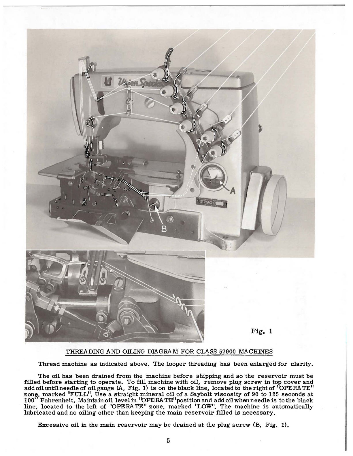
Fig.
1
Thread
The
filled
add
zong.
100
line,
lubricated
before
oil
until
marked
Fahrenheit.
located
Excessive
THREADING
machine
oil
has
starting
needle
''FULL".
to
and
no
oil
been
of
oil gauge
Maintain
the
left
oiling
in
the
AND
OILING
as
indicated
drained
to
operate.
Use a straight
other
from
(A,
oil
level
of
''OPERATE"
than
main
reservoir
above.
the
To
fill
Fig.
1)
mineral
in
''OPERA
keeping
DIAGRAM
The
looper
machine
machine
is
on
the
oil
TE"position
zone,
may
the
marked
main
be
FOR
CLASS
threading
before
with
black
of a Saybolt
drained
shipping
oil,
line,
and add
''LOW".
reservoir
at
remove
the
5
57900
has
and
plug
located
viscosity
oil
The
filled
plug
MACHINES
been
enlarged
so
the
reservoir
screw
to
the
right of·''OPERA
of
90
when
needle
machine
is
necessary.
screw
(B,
for
in
top
cover
to
125
seconds
is
'to
is
automatically
Fig.
1).
clarity.
must
the
black
be
and
TE"
at
Page 6

H
VAPOR
~~
SPLASH
OIL
i!
oiL
B
oiL
ACTION
RESERVOIR
FEED
RETURN
SCR
E W
-PASS
WIT
OUTLET
BY
6
H
Page 7
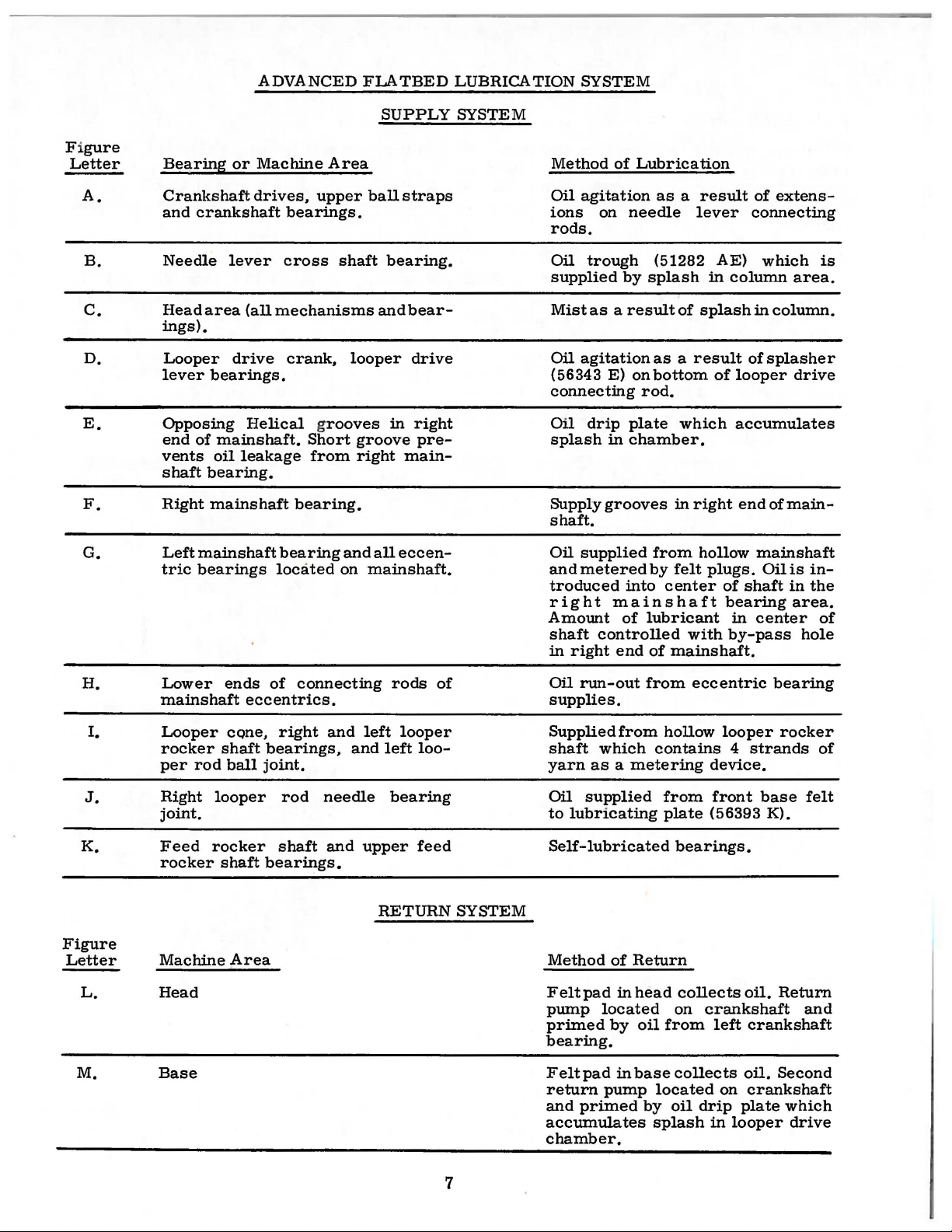
ADVANCED
FLATBED
LUBRICATION
SYSTEM
F i
gure
Letter
A.
B.
c.
D.
E.
F.
G.
Bearing
Crankshaft
and
Needle
Head
ings).
Looper
lever
Opposing
end
vents
shaft
Right
Left
tric
or
crankshaft
lever
area
drive
bearings.
of
mainshaft.
oil
bearing.
mainshaft
main
bearings
Machine
drives,
(all
mechanisms
Helical grooves
leakage
shaft
bearing
located
Area
upper
bearings.
cross
crank,
shaft
Short
from
bearing.
on
and
SUPPLY
ball
straps
bearing.
and
looper
in
groove
right
main-
all
eccen-
mainshaft.
bear-
drive
right
pre-
SYSTEM
Method
Oil
ions
rods.
Oil
supplied
Mist
Oil
(56343
connecting
Oil
splash
Supply
shaft.
Oil
andmeteredby
troduced
right
Amount
shaft
in
of
agitation
on
trough
by
as a result
agitation
E)
drip
in
grooves
supplied
mains
of
controlled
right
end
Lubrication
needle
on
rod.
plate
chamber.
into
as a result
lever
(51282
splash
as a result
bottom
from
lubricant
of
in
of
splash
which
in
right
hollow
felt
plugs.
center
haft
with
mainshaft.
of
extens-
connecting
AE)
which
column
in
column.
of
splasher
of
looper
accumulates
end
of
mainshaft
Oilis
of
shaft
bearing
in
center
by-pass
area.
drive
main-
in-
in
the
area.
hole
is
of
H.
I.
J.
K.
Figure
Letter
L.
M.
Lower
mains
Looper
rocker
per
Right
joint.
Feed
rocker
Machine
Head
Base
haft
rod
looper
rocker
ends
eccentrics.
cone,
shaft
bearings,
ball
joint.
shaft
bearings.
Area
of
connecting
right
rod
shaft
and
and
needle
and
upper
rods
left
looper
left
bearing
RETURN
of
loo-
feed
SYSTEM
Oil
run-out
supplies.
Supplied
shaft
yarn
Oil
to
Self-lubricated
Method
Felt
pump
primed
bearing.
Felt
return
and
accumulates
chamber.
which
as a metering
supplied
lubricating
pad
pad
primed
from
from
of
Return
in
head
located
by
oil
in
base
pump
by
eccentric
hollow
contains 4 strands
from
plate
bearings.
on
from
collects
located
oil
splash
looper
device.
front
(56393 K).
collects
crankshaft
left
on
drip
in
bearing
rocker
base
oil.
Return
crankshaft
oil.
Second
crankshaft
plate
which
looper
drive
of
felt
and
7
Page 8
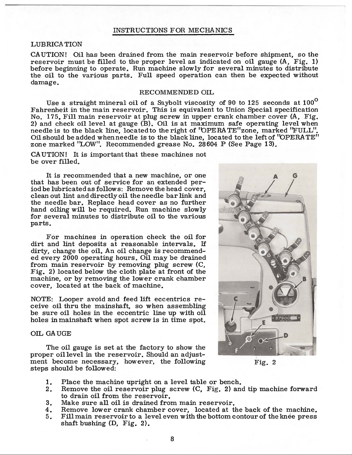
LUBRICATION
INSTRUCTIONS
FOR
MECHANICS
CAUTION!
reservoir
before
the
beginning
oil
to
damage.
Use a straight
Fahrenheit
No.
175.
Fill
2)
and
check
needle
Oil
zone
is
should
marked
to
CAUTION!
be
over
that
iod
clean
the
hand
for
filled.
It
is
has
been
be
lubricated
out
needle
oiling
several
recommended
lint
parts.
Oil
must
the
various
in
the
main
oil
the
be
added
''LOW".
It
is
out
and
bar.
will
minutes
has
been
be
filled
to
operate.
mineral
main
reservoir
level
black
line,
when
Recommended
important
of
service
as
follows:
directly
Replace
be
required.
to
drained
to
the
Run
parts.
oil
reservoir.
at
at
gauge
located
needle
that
that a new
for
Remove
oil
the
head
cover
Run
distribute
from
proper
machine
Full
the
level
speed
main
as
slowly
operation
RECOMMENDED
of
a S3.ybolt
This
plug
(B).
Oil
to
is
to
the
grease
these
machine,
an
extended
the
needle
machine
oil
screw
the
machines
head
bar
as
to
viscosity
is
equivalent
in
is
at
right
black
No.
or
cover,
link
no
further
slowly
the
various
upper
maximum
of
line,
per-
reservoir
indicated
for
OIL
crank
''OPERA
located
28604
not
one
and
several
can
then
of
90
to
Union
safe
TE"zone,
P
(See
before
on
oil
minutes
be
to
125
Special
chamber
operating
to
the
Page
shipment,
gauge
to
expected
seconds
specification
cover
marked
left
of
''OPERATE"
13).
so
(A,
Fig.
distribute
without
at
(A,
level
when
''FULL".
the
1)
100°
Fig.
For
dirt
and
dirty,
ed
from
Fig.
change
every
main
2)
machine,
cover,
NOTE:
ceive
be
holes
OIL
oil
sure
in
GAUGE
The
proper
ment
steps
become
should
1.
2.
3.
4.
5.
machines
lint
deposits
the
2000
operating
reservoir
located
or
by
located
Looper
thru
the
oil
holes
mainshaft
oil
gauge
oil
level
be
Place
Remove
to
drain
Make
Remove
Fill
main
shaft
bushing
in
oil.
An
by
below
the
removing
at
the
back
avoid
and
mainshaft,
in
the
when
is
set
in
the
reservoir.
necessary,
followed:
the
machine
the
oil
oil
from
sure
all
lower
reservoir
(D,
operation
at
reasonable
oil
change
hours.
removing
cloth
the
lower
of
machine.
feed
so
eccentric
spot
screw
at
the
however,
upright
reservoir
the
reservoir.
oil
is
drained
crank
chamber
to a level
Fig.
check
is
Oil
may
plug
plate
crank
lift
eccentrics
when
line
is
factory
Should
on a level
plug
2).
the
oil
intervals.
recommend-
be
drained
screw
at
front
of
chamber
assembling
up
with
in
time
to
show
an
adjust-
the
following
screw
from
main
cover,
even
with
for
If
(C,
the
re-
oil
spot
.
the
table
or
bench.
(C, Fig. 2)
reservoir.
located
the
bottom
at
and
tip
the
back
contour
Fig.
2
machine
of
the
of
the
forward
machine.
knee
press
8
Page 9
6.
Loosen
or
of
7.
Tighten
cover.
8.
Add
''OPERATE"
lock
nut
right
until
''OPERATE"
lock
oil
so
that
zone,
(E)
the
zone,
nut
gauge
OIL
on
gauge
marked
(E),
needle
marked
GAUGE
calibrating
needle
"LOW".
replace
rests
''FULL".
(Continued)
screw
rests
plug
on
on
screw
the
(F),
the
black
and
black
(C)
and
line,
turn
line,
lower
the
screw
located
located
crank
to
the
to
the
to
the
chamber
right
left
left
of
Align
and
test
Machine
Style
57900
H-5-8
the
plate
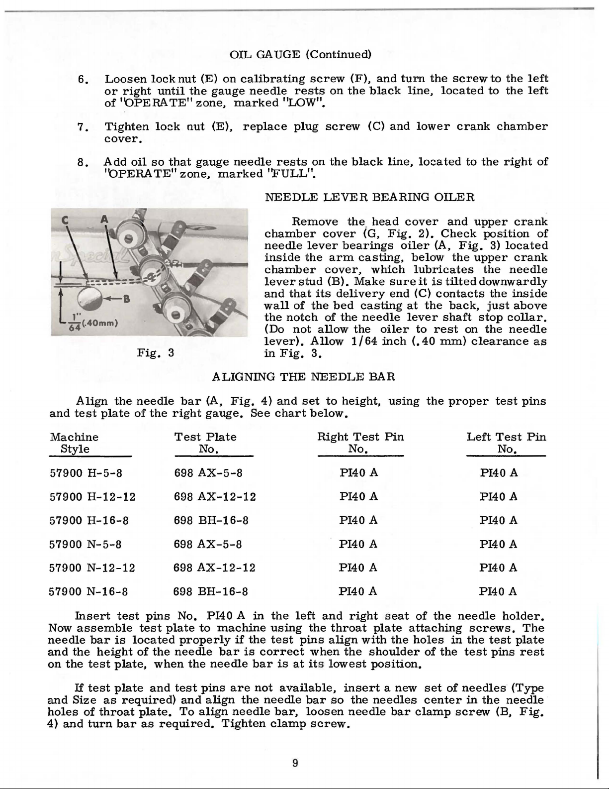
Fig.
needle
of
the
3
bar
right
Test
698
ALIGNING
(A,
Fig.
gauge.
See
Plate
NEEDLE
Remove
chamber
needle
inside
chamber
lever
and
that
wall
the
(Do
of
notch
not
lever).
in
Fig.
THE
4)
and
chart
LEVER
cover
lever
the
arm
cover,
stud
(B).
its
the
of
allow
Allow
3.
NEEDLE
set
to
below.
Right
the. head
bearings
casting,
Make
delivery
bed
casting
the
the
1/64
height,
Test
No. No.
AX-5-8
PI40
BEARING
(G,
Fig.
oiler
which
sure
end
needle
oiler
inch
BAR
using
Pin
A
OILER
cover
2).
Check
(A,
below
lubricates
it
is
(C)
contacts
at
the
lever
(.40
to
shaft
rest
mm)
the
and
Fig.
the
tilted
back,
on
clearance
proper
Left
upper
crank
position
3)
located
upper
the
crank
needle
downwardly
the
inside
just
above
stop
collar.
the
needle
test
pins
Test
Pin
No.
PI40
A
of
as
57900
57900
57900
57900
57900
Insert
Now
needle
and
the
on
the
If
and
Size
holes
4)
and
H-12-12
H-16-8
N-5-8
N-12-12
N-16-8
test
assemble
bar
is
height
test
plate,
test
plate
as
of
throat
turn
bar
pins
test
plate
located
of
the
when
and
required)
plate.
as
required.
698
AX-12-12
698
BH-16-8
698
AX-5-8
698
AX-12-12
698
BH-16-8
No.
PI40 A in
to
properly
needle
the
test
pins
and
align
To
align
machine
if
bar
needle
are
the
needle
Tighten
the
is
correct
bar
not
the
using
test
is
at its
available,
needle
bar,
clamp
9
left
the
pins
when
bar
loosen
PI40
PI40
PI40
PI40
PI40
and
throat
align
lowest
so
screw.
right seat
the
insert a new
the
needle
A
A
A
A
A
plate
with
the
shoulder
position.
needles
bar
of
the
attaching
holes
of
set
in
the
of
center
clamp
PI40
PI40
PI40
PI40
PI40
needle
screws.
the
test
needles
in
the
screw
holder.
test
pins
needle
(B,
A
A
A
A
A
The
plate
rest
(Type
Fig.
Page 10
SYNCHRONIZING
LOOPER
AND
NEEDLE
MOTIONS
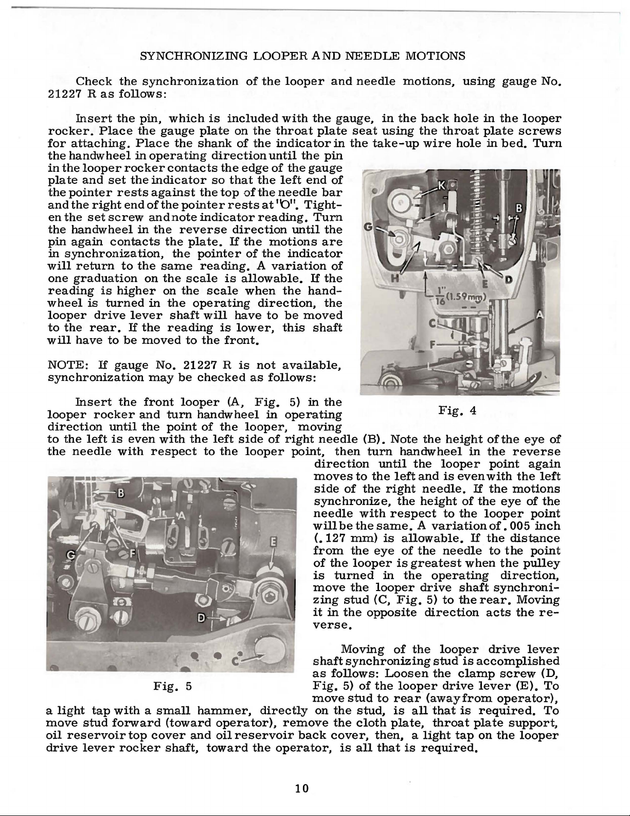
Check
21227 R as
Insert
rocker.
for
attaching.
the
handwheel
in
the
looper
plate
the
and
en
the
pin
in
will
one
and
pointer
the
the
set
handwheel
again
synchronization,
return
graduation
reading
wheel
is
looper
to
the
will
have
NOTE:
Place
set
right
screw
is
turned
drive
rear.
to
If
the
follows:
the
rocker
rests
end
contacts
to
higher
If
be
gauge
synchronization
synchronization
pin,
which
the
gauge
Place
in
operating
the
plate
shank
contacts
the
indicator
against
of
and
in
the
on
in
lever
the
moved
may
the
the
the
same
the
on
the
reading
No.
the
pointer
note
indicator
reverse
plate.
the
pointer
reading.
scale
the
operating
shaft
to
21227 R is
be
checked
is
included
on
direction
the
so
that
top
rests
direction
If
is
scale
will
is
the
front.
of
the
the
throat
of
the
indicator
until
edge
of
the
left
of
the
needle
at
''0".
reading.
the
motions
of
the
A
variation
allowable.
when
direction,
have
to
lower,
not
as
follows:
looper
with
the
plate
the
pin
the
gauge
end
bar
Tight-
Turn
until
the
are
indicator
If
the
the
hand-
the
be
moved
this
shaft
available,
and
needle
gauge,
seat
in
the
of
of
motions,
in
the
using
take-up
back
the
wire
using
hole
throat
hole
gauge
in
the
plate
in
bed.
No.
looper
screws
Turn
Insert
looper
direction
to
the
left
the
needle
a
light
move
oil
drive
stud
reservoir
lever
the
rocker
until
is
even
with
tap
with a small
forward
top
rocker
front
and
the
with
respect
Fig.
cover
looper
turn
handwheel
point
of
the
5
hammer,
(toward
and
shaft,
(A,
the
left
side
to
the
operator),
oil
reservoir
toward
Fig.
in
looper,
of
looper
directly
the
operator,
5)
in
the
operating
moving
right
needle
point,
direction
moves
side
synchronize,
needle
will
(.
127
from
of
is
move
zing
it
in
verse.
shaft
as
Fig.
move
on
remove
back
(B).
then
turn
until
to
the
of
the
right
with
be
the
same. A variation
mm)
the
the
looper
turned
the
stud
the
is
eye
in
looper
(C,
opposite
Moving
synchronizing
follows:
5)
stud
the
the
cover,
is
Loosen
of
the
to
stud,
cloth
then, a light
all
that
Note
the
handwheel
the
left
and
needle.
the
height
respect
allowable.
of
the
is
greatest
the
operating
drive
Fig.
5)
direction
of
the
stud
the
looper
rear
is
plate,
(awayfrom
all
that
throat
is
required.
Fig.
height
looper
is
even
of
to
the
needle
when
shaft
to
the
looper
is
clamp
drive
is
tap
4
of
the
eye
in
the
reverse
If
the
looper
If
point
with
the
of.
the
to
again
the
motions
eye
of
005
distance
the
the
pulley
point
point
direction,
synchroni-
rear.
acts
drive
Moving
the
lever
accomplished
screw
lever
(E).
operator),
required.
plate
on
support,
the
looper
of
left
the
inch
re-
(D,
To
To
10
Page 11
SYNCHRONIZING
LOOPER
AND
NEEDLE
MOTIONS
(Continued)
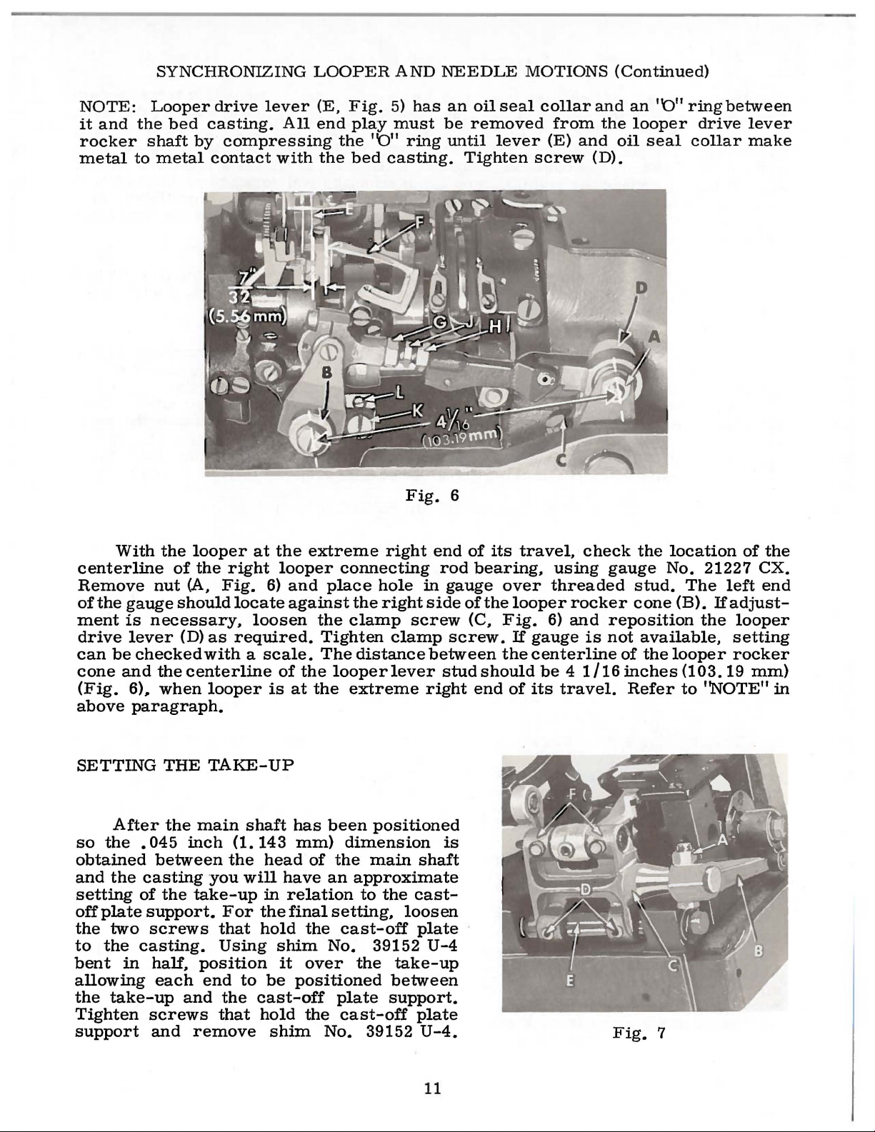
NOTE:
it
and
rocker
metal
Looper
the
shaft
to
metal
bed
drive
casting.
by
compressing
contact
lever
All
with
(E,
end
the
Fig.
play
the
bed
5)
must
''0"
ring
casting.
Fig.
has
an
oil
be
removed
until
Tighten
6
seal
lever
collar
from
(E)
screw
and
and
(D).
the
oil
an
''0"
looper
seal
ring
drive
collar
between
lever
make
With
centerline
Remove
of
the
gauge
ment
drive
can
cone
(Fig.
above
SETTING
so
obtained
and
setting
offplate
the
to
bent
allowing
the
Tighten
support
is
lever
be
checked
and
6)..,
paragraph.
After
the
• 045
the
of
two
the
casting.
in
take-up
the
looper
of
the
nut
(A,
should
necessary,
(D)
with a scale.
the
centerline
when
THE
the
between
casting
the
support.
screws
half,
each
screws
and
looper
TAKE-UP
main
inch
you
take-up
position
end
and
remove
right
Fig.
locate
as
required.
shaft
(1.
the
will
For
that
Using
to
the
that
at
the
looper
6)
and
against
loosen
of
the
is
at
has
143
mm)
head
have
in
relation
the
final
hold
shim
it
be
positioned
cast-off
hold
shim
extreme
connecting
place
the
the
clamp
Tighten
The
distance
looper
the
extreme
been
dimension
of
the
an
approximate
setting,
the
cast-off
No.
over
the
the
plate
cast-off
No.
right
hole
right
screw
clamp
lever
positioned
main
to
39152
39152
shaft
the
cast-
loosen
plate
take-up
between
support.
plate
U-4.
end
of
rod
bearing,
in
gauge
side
of
(C,
screw.
between
stud
right
U-4
end
is
its
travel,
over
the
looper
Fig.
If
the
should
of
check
using
threaded
rocker
6)
and
gauge
centerline
be 4 1/16
its
is
travel.
the
location
gauge
reposition
not
of
Fig.
No.
stud.
cone
(B).
available,
the
looper
inches
Refer
7
21227
The
If
the
(103.
to
''NOTE"
of
CX.
left
end
adjust-
looper
setting
rocker
19
mm)
the
in
11
Page 12
SETTING
THE
LOOPER
Insert a new
The
distance
looper
to
setting.
and
obtain
nut
the
nut
(G).
(F)
should
right.
If
adjustment
(H)
the
7/32
Make
on
adjustment.
The
looper
the
needles.
needles.
If
adjustment
(L)
as
required.
turning
it
counterclockwise
makingthis
is
obtained
needle-looper
accomplished
clamping
loopers
set
of
needles.
from
Looper
the
be
center
7/32
gauge
is
connecting
inch
(5.
56
sure
its
the
is
set
point
is
left
correctly
brushes.
necessary.
Turning
adjustmentmay
and
recheck
relationship.
by
applying
in
looper
SETTING
type
of
the
inch
(5. 56
No.
21225-7/32
required.
rod
(J).
mm)
dimension.
ball
joint
but
stop
screw
acts
prove
the
adjustment.
A
minute
pressure
rocker.
HEIGHT
and
right
mm)
loosen
turn
the
is
in
in
line-of-feed.
does
not
loosen
lock
clockwise
the
reverse.
helpful.
adjustment
on
the
so
as
size
as
needle
when
can
nut
the
beused
(G.
connecting
Retighten
vertical
pick
screw
Holding
Tighten
Insert
of
loopers
to
get
OF
NEEDLE
specified.
(E.
Fig.
looper
6)
is
advantageously
Fig.
6)
(it
rod
both
nuts.
position
if.
as
it
moves
at
the
rear
(K.
Fig.
sets
back
lock
the
the
loopers
screw
looper
looper-needle
at
front
the
or
proper
BAR
Also
to
at
insert
the
its
point
farthest
has a left
forward
first
and
of
6)
loopers
does
to
the
and
or
nut
the
right
turn
to
to
not
the
the
securelyafter
and
obtain
relationship
back
of
the
in-line-of-feed
front
of
looper.
the
position
tocheck
hand
thread)
backward
(H)
and
bind
left.
and
stop
behind
center
screw
rear
front
setting
the
can
blade.
setting.
front
this
to
then
after
and
while
same
be
while
The
stitch
when
If
down
ment
equal
needle's
the
adjustment
as
of
clearance
The
in
the
throat
travel
ance
clamps
ward
by
move
rocker
set.
in
the
the
or
loosening
the
arm
The
3/64
point
holds
tighten
nut
inch
(F.
of
the
screw
Fig.
clockwise
height
eye
point
of
is
required
the
needle
feed
dog
plate.
it
may
front
feed
rearward
screws
feed
rocker
(B)
tips
of
(1. 19
mm)
travel.
feed
dog
(A).
5)
and
to
raise
of
the
needle
is
3/64
looper.
necessary.
and
retighten
bar
while
on
both
should
NOTE:
be
necessary
and
rear
rockerarm
as
needed
(D)
which
to
does
the
not
feed
above
The
height
in
position.
If
feed
turn
__
the
front
bar
inch
moving
loosen
making
the
right
SETTING
be
set
See
of
throat
(B)
and
hold
desired
bind
after
dog tee
the
can be
dog te
screw
teeth.
(A.
Fig.
(1.19
to
the
screw
screw.
and
for
maximum
;'CHANGING
to
centralize
plate.
to
the
retighten
the
position
making
th
should extend 1 1/4
throat
plate
adjusted
turn
height adjus
eth
are
(G)
clockwise
Retighten
4)
mm)
left.
below
is
(B)
Care
this
left
THE
must
adjustment.
sides
FEED
travel
STITCH
feed
If
required.
feedrocker
nut.
feed
rocker
and
retighten
this
and parallel
by
not
parallel
nut
is
correct
the
even
and
with
reposition
be
taken
of
the
DOG
and
LENGTH".
dog
(C)
and
Equal
side
(C)
adjustment.
loosening
ting
screw
to
lower
(F)
when
when
underside
the
left
not
as
the
needle
equal
motion
clearance
to
loosen
move
clearance
onto
the
screws.
tooth
with
depth
the
screw
(B)
with
the
the
front
feed
the
top
of
the
side
needle
to
disturb
needles
slots
With
obtain
nut
(A.
the
feed
feed
rocker
Make
or
throat
(A.
as
required
throat
teeth.
dog
is
of
the
left
front
of
bar
in
throat
maximum
equal
Fig.
this
the
are
on
looper.
needle.
(A)
up
align-
to
plate.
all
sides
clear-
7)
which
have
feed
rockerfor-
can
be
obtained
shaft
sure
the
(E).
feed
approximately
plate
Fig.
plate.
set
at high
8)
and
loosen
or
counter-
properly.
which
re-
602
or
12
Page 13
(C.
and
in
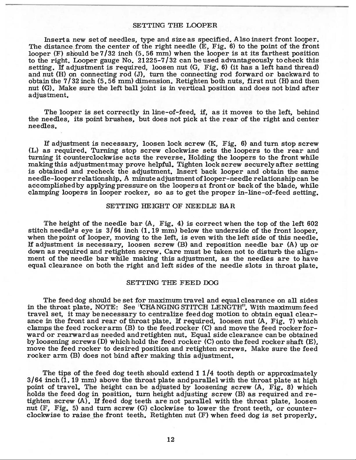
Set
Fig.
turning
the
head
the
8)
stitch
1/2
the
of
to
turn
stitch
the
main
required
(it
has a left
adjusting
shaft
CHANGING
length.
hand
screw
(E)
..
which
STITCH
This
is
thread)
(D)
located
is
LENGTH
accomplished
on
the
end
under
marked
the
with
of
by
the
left
"L"
end
loosening
stitch
and
regulating
of
the
''S".
the
locknut
cloth
plate,
Turning
stud
the
screw
and
regulating
structive
''U"
NOTE:
rear
clockwise
turning
shaped
Any
needle
it
stud
damage
key
change
guard
Machines
require
with
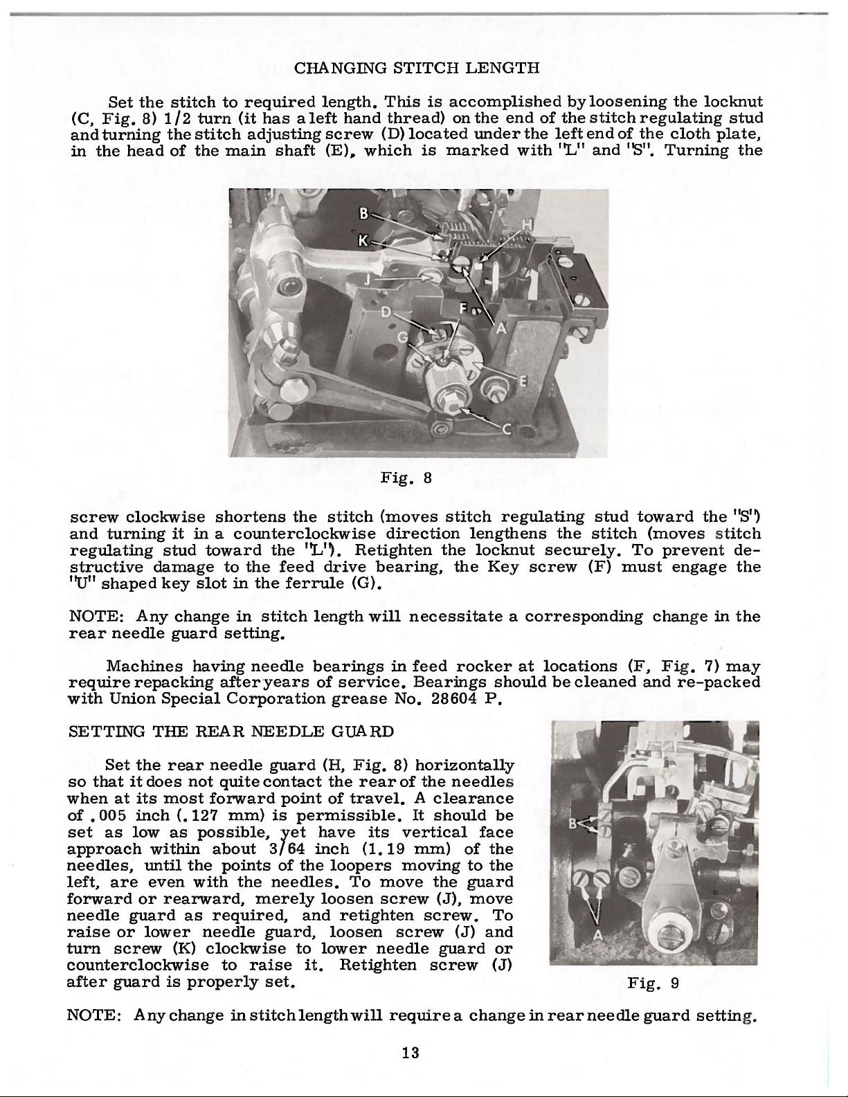
SETTING
so
when
of
•
set
approach
needles,
left,
forward
needle
raise
turn
Union
Set
that
at
005
as
are
or
screw
repacking
Special
THE
the
rear
it
does
its
inch
low
not
most
(.127
as
within
until
the
even
or
rearward,
guard
as
lower
(K)
counterclockwise
after
guard
is
properly
shortens
the
stitch
in a counterclockwise
toward
to
slot
in
in
the
the
stitch
the
feed
ferrule
''L''·
drive
length
Retighten
(G).
setting.
having
REAR
needle
forward
possible,
with
needle
clockwise
needle
afteryears
Corporation
NEEDLE
guard
quite
contact
point
mm)
is
yet
about
points
the
3/64
of
needles.
merely
required,
guard,
to
raise
bearings
of
service.
grease
GUARD
(H.
Fig.
the
of
travel.
permissible.
have
inch
the
loopers
To
loosen
and
retighten
loosen
to
lower
it.
Retighten
set.
Fig.
(moves
direction
bearing,
will
in
No.
8)
rear
its
(1.
19
move
screw
needle
8
stitch
the
the
necessitate
feed
rocker
Bearings
28604
horizontally
of
the
needle
A
clearance
It
should
vertical
mm)
moving
the
(J),
screw.
screw
(J)
guard
screw
regulating
lengthens
locknut
Key
a
at
should
P.
s
be
face
of
the
to
the
guard
move
To
and
or
(J)
stud
the
stitch
securely.
screw
(F)
must
corresponding
locations
be
cleaned
toward
the
(moves stitch
To
prevent
engage
chan
ge
(F. Fig. 7)
and
re-packed
Fig.
9
"S'~
de-
the
in
the
may
NOTE:
Any
change
in
stitch
length
will
require a change
13
in
rear
needle
guard
settin
g.
Page 14
Set
the
ward
brush
vertical
of
the
the
but
face
needle.
rightneedle
(A,
Fig.
9),
lower
tighten
or
screws
front
path
not
push
at
rotate
rotate
needle
of
the
pick
at
the
The
front
anytime.
needle
needle
after
SETTING
guard
front
this
needle.
needle
needle
To
guard
guard,
guard
so
looper
until
move
holder
loosen
is
properly
FRONT
that
as
It
should
the
guard
needle
NEEDLE
it
pushes
it
moves
be
point
of
should
guardforward
as
required
screws
(B),
set.
the
behind
set
the
not
contact
GUARD
left
602
the
needle.
as
low
as
looper
is
the
orrearward,
and
retighten
reposition
stitch
needle
The
possible,
just
past
rear
needle
screws.
as
necessary
looper
yet
the
loosen
To
back
have
left
guard
screws
raise,
andre-
to-
may
its
side
or
NOTE:
A
setting.
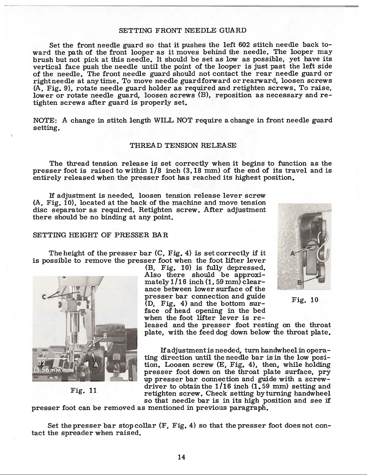
The
presser
entirely
If
adjustment
(A,
Fig.
disc
there
separator
should
SETTING
The
is
possible
change
thread
foot
is
released
10),
located
be
HEIGHT
height
to
remove
in
tension
raised
when
is
as
required.
no
binding
OF
of
the
stitch
length
THREAD
release
to
within
the
needed,
at
the
at
PRESSER
presser
the
presser
1/8
presser
loosen
back
of
Retighten
any
bar
(B,
Also
mately
ance
presser
(D,
face
when
leased
plate,
WILL
TENSION
is
set
inch
foot
tension
the
point.
BAR
(C,
Fig.
foot
Fig.
there
between
Fig.
of
the
with
NOT
correctly
(3.18
has
reached
machine
screw.
4)
when
10)
should
1/16
inch
bar
connection
4)
and
head
foot
and
the
the
require a change
RELEASE
when
mm)
release
and
After
is
set
the
foot
is
fully
(1.
lower
the
opening
lifter
presser
feed
it
begins
of
the
its
highest
lever
move
screw
tension
adjustment
correctly
lifter
depressed.
be
approxi-
59
mm)
clear-
surface
of
and
bottom
in
the
lever
is
foot
dog down
lever
guide
in
end
if
it
the
sur-
bed
reresting
below
front
to
of
needle
function
its
travel
position.
on
the
throat
Fig.
the
guard
as
the
and
is
10
throat
plate.
If
presser
Set
tact
the
Fig.
foot
can
the
presser
spreader
1
1
be
when
removed
bar
stop
raised.
ting
tion.
presser
up
driver
retighten
so
as
mentioned
collar
adjustment
direction
Loosen
presser
to
that
needle
(F,
Fig.
foot
bar
obtain
screw.
in
4)
14
is
needed,
until
the
screw
down
on
connection
the
1/16
Check
bar
is
previous
so
that
(E,
turn
needle
Fig.
the
4),
throat
and
inch
setting
in
its
high
paragraph.
the
presser
handwheel
bar
is
in
then,
plate
guide
(1.
59
mm)
byturning
position
foot
in
opera-
the
low
posi-
while
surface,
holding
pry
with a screw-
setting
and
handwheel
and
see
does
not
con-
if
Page 15

The
Nos.
mm)
a
made
5-8
for
scale
by
required
its
arc
loosening
ecting
link
arc
travel
and
16-8
gauge
between
loosening
to
obtain
travel
nut
is
(J)
properly.
No.
the
equal
and
of
the
on
Styles
12-12
two
nut
the
desired
moving
SETTING
spreader
on
extreme
(G,
Fig.
distance
57900
Styles
4)
amount
to
the
spreader
THE
should
Hand
57900
spreader
and
moving
of
the
center
SPREADER
be
set
at
N.
This
Hand
N.
arc
the
arc
travel.
of
rocker
shaft
9/16
inch
setting
should
Measurementis
travel
points.
connecting
Set
the
its
arc.
arm
This
(K)
(14.
29
mm)
be
5/8
made
Adjustment
link
(H)
up
connecting
is
accomplished
to
position
for
gauge
inch
(15.
byplacing
can
or
down
link
so
the
conn-
88
be
as
that
by
With
end
of
its
left
of
the
(A,
Fig.
Retighten
3/32
inch
complished
the
needle
stroke,
centerline
12)
and
screws.
Fig·
(2.
12
38
mm)
by
loosening
bar
the
upper
of
the
rotating
and
in
its
spreader
center
spreader
CAUTION:
thrust
ing
spreader
1/64
Styles.
inch
Style
throat
Adjustment
12)
11)
be
kept
screws
up
position,
needle.
screws
The
and
The
should
close
(C)
point
This
holder
The
collar
(A,
shaft
spreader
to
17 32
The
(8.
33
mm)
57900 H
plate
on
can
position
left
edge
clear
to
the
and
moving
and
the
should
is
(B)
to
spreader
for
the
Fig.
and
inch
bottom
above
and
machine
be
spreader
of
the
top
spreader
extend
7/32
accomplished
position
holder
spreader
12)
be
up
on
the
should
(.
of
40
the
clear
to • 79
spreader
the
27/64
inch
Style
made
by
loosening
as
the
spreader
of
the
right
the
guide
needle
spreader.
(A,
inch
by
the
upper
shaft,
sure
to
spreader
the
mm)
throat
(10.
57900
required.
thread
as
necessary.
Fig.
(5.
11)
56
loosening
spreader
is
also
so
when
push
holder.
left
needle
on
all
should
plate
72
mm)
N ('X",
screws
guide
by
approximately
This
at
mm)
the
tighten-
down
shank
machine
be
on
machine
above
Fig.
(C,
(B,
can
the
left
to
the
screws
point.
lower
on
the
by
21/64
the
12).
Fig.
Fig.
be
ac-
For
best
The
Needle
the
The
The
Needle
The
Pull
tension
Needle
Needle
Looper
nuts
all
results
602
loops
loops
left
needle
401
loops
seam
threads
to
threads
threads
gauges
and
THREAD
the
stitch
do
not
stitch
may
obtain
following
must
may
hang
have
loop
must
may
be
grin
through
the
for
Styles
for
Styles
be
may
be a medium
pulled
or
following
pulled
down
to
be
open
the
proper
conditions
up
as
much
alike.
pull
in
up
between
up
to
tensions:
57900
57900
----·--------------------------------------
spreader
threads---------------------------
TENSIONS
are
desirable:
unpuckered.
as
1/3
slightly.
tight
stitch.
1/64
1/64
inch
eyelets,
H-5-8
H-12-12
and
and
of
to
(.40
per
Fig. 1 and
H-16-8
57900
one
1/32
15
stitch
inch
mm).
-------
N,
and
(.
40
adjust
4
5
2
within
to • 79
the
oz.
(113.40
oz.
(141.
oz.
(56.
this
range
mm).
applicable
gr).
74
gr).
70
gr).
Page 16

Set
eyelet
the
57900
(19.
the
inch
(A,
center
H-12-12
05
mm)
spreader
(12.
mounting
thread
ble
frame
without
stroke.
SETTING
the
401
Fig.
13) 1
of
its
and
on
all
thread
70
mm)
screw.
eyelet
drawing
NEEDLE
stitch
needle
inch
mounting
57900
other
frame
below
Set
the
(C)
thread
AND
thread
(25. 4 mm)
screw
N-12-12;
machine
eyelet
the
center
602
stitch
as
high
on
SPREADER
frame
above
on
Styles
3/4
inch
Styles.
(B).
of
Set
1/2
the
needle
as
possi-
the
down-
THREAD
FRAME
EYELETS
SETTING
TAKE-
Set
Fig.
13)
thread
is
needle
bar
Lower
thread
eyelet
even
bar
has
this
loop,
SETTING
The
is
not
spotted
ing
conditions.
NEEDLE
UP
the
needle
THREAD
WIRE
thread
locatedadjacent
(E)
so
that
with
completed
looper
the
thread
setting
or
raise
LOOPER
thread
on
the
It
is
top
eyelet,
its
for a smaller
THREAD
mainshaft
set
take-up
to
the
its
upper
of
the
holes
when
downward
it
for a larger
TAKE-UP
take-up
(A,
correctly
lobe
clearly
cast-off
determines
Moving
screw
cones,
slots
should
treme
tioning
graph
wire
needle
bar
surface
in
the
needle
stroke.
needle
loop.
Fig.
and
consequently,
when
of
the
take-up
visible
plate
the
support
slots
(C)
moving
causes
just
less
become
position
before
"SETTING
(D,
the
14)
the
looper
below
support
amount
(B)
causes
same;
thread
to
the
securing
THE
when
up
taut
TAKE-
can
be
thread
the
the
underside
(B)
is
of
thread
towards
more
down
to
towards
be
as
left.
Check
support
set
to
is
just
point
adjustable
pulled
the
thread
pulled.
the
loopers
(B)
UP'~
for
Fig.
13
compensate
cast
of
of
the
the
off
left
and
off
by
bottom
to
the
be
The
of
pulled
top
looper
reach
out
right
as
described
final
setting.
for
the
needle
looper.
its
the
take-up.
its
mounting
from
of
its
threads
their
to
left
in
vary-
highest
is
The
setting
the
screw
ex-
posi-
para-
The
401
Fig.
Regulate
enough
is
bar
pressureon
placed
in
the
clockwise
an
independent
the
chain
on
head
acts
and
14
the
presser
the
fabric.
of
the
the
pressure
stopping
the
presserfoot
This
machine.
reverse.
adjusting
chain
stitch
adjustable
looper
the
602
PRESSER
and
thread
thread
into
FOOT
spring regulating screw
to feed the
is
the
knurled screw.
Turning
The
401 stitch
it
screw
cuttin
g.
looper
can
be
the
setting.
PRESSURE
clockwi
chaining
(L, Fig.
thread
positioned
401
stitch
(F.
workuniformlywhen
located
se
increases
4)
16
Fig.
directly
section
for
best
eyelets
to
reduce
system
13)
so
the
of
the
control
(D,
Fig.
or
without
that
it
exerts
a
slight
behind
pressure,
presser
on
14)
put
more
changing
tension
the
needle
counter-
foot has
feeding
are
only
out
Page 17

of
The
the
cutting
throat
edge
plate
ADJUSTING
of
the
(B).
This
lower
can
TRIMMER
knife
be
(A,
accomplished
MECHANISM
Fig.
15)
should
by
be
set
loosening
level
screw
with
(C),
the
move
top
lower
lower
complished
to
When
The
rear.
knife
knife
move
desired
shear
This
up
should
by
knife
angle
adjustment
counterclockwise
screws
screws
blade.
lished
upward
(J).
screw.
knife
turn
NOTE:
bear
(F)
(E).
The
upper
Positioning
by
loosening
or
When
desired
Should
become
eccentric
Upper
against
& (G)
downward
upper
or
down
be
aligned
loosening
to
the
left
position
of
the
and
screw
in
the
knife
should
of
knife
screw
can
position
forward
necessary,
pin
(L)
as
knife
lever
knife
as
required
screw
and
of
knife
lower
can
be
opposite
be
to
(H,
be
accomplished
of
knife
or
rearward
loosen
required.
thrust
lever.
with
(D),
turning
has
knife
made
(G)
clockwise
direction
set
the
left
Fig.
has
Allen
Retighten
bracket
Fig.
and
the
center
turn
it
away
been
should
by
loosening
to
trim
or
right
15).
been
repositioning
head
15
retighten
of
screw
from
screw.
the
(A,
the
obtained,
be
set
at
about 1 degree,
screws
until
will
the
the 1 degree
decrease
full
length
can
be
Positioning
by
loosening
obtained,
screws
Allen
head
(G, Fig. 13)
The
right
Fig.
needle.
16)
operator
retighten
(E)
the
of
its
accomp-
of
knife
screw
retighten
of
upper
(K),
then
screws.
should
toward
screw
and
is
shear
trimming
This
the
acts
the
(D,
yielding
turning
obtained,
angle.
Fig.
edge
can
be
operator
reverse.
Fig.
15).
to
screw
turning
Retighten
16
of
ac-
the
(F)
ORDERING
REPAffi
PARTS
ILLUSTRATIONS
This
views
in
their
found a listing
pieces
catalog
of
various
actual
required
has
sections
position
of
the
parts
in
the
been
in
of
the
arranged
the
machine.
with
particular
to
simplify
mechanism
On
their
view
part
being
are
shown
the
page
number,
shown.
ordering repair
opposite
description,
17
so
that
the
parts.
the parts
illustration
and
Exploded
may
the
number of
be
will
seen
be
Page 18

ORDERING
REPAIR
PARTS
ILLUSTRATIONS
the
position
in
ordering
Numbers
in
of
that
parts.
Component
indicated
assembly.
Ref.
by
Example:
Part
indenting
No. No.
62
63
64
65
66
not
commended,
in
this
the
29105
22559
56343
56343
22587
It
will
listed.
At
the
book.
part
AJ
A
E
c
K
be
noted
The
so
back
This
number
(Continued)
the
first
part
in
Always
parts
of
their
Looper
in
the
reason
the
of
will
is
is
complete
the
book
facilitate
known.
column
the
use
are
reference
illustration.
the
part
sub-assemblies
descriptions
Driving
Bearing
Oil
Ball
Bearing
example
that
Cap
Splasher
Joint
Guide
Cap
shown
replacement
sub-assembly
will
be
found a numerical
locating
Reference
number
which
under
numbers
listed
can
the
only.
numbers
in
the
second
be
furnished
description
Description
Lever
Screw.
Crarik
Assembly
lower----------------------
---------------------------------Fork
S~rew.
above
should
the
--------------------------
upper----------------------
that
the
eccentric
of
these
illustration
parts
be
ordered.
index
individually
of
and
and
merely
should
never
column.
for
of
the
--------------
and
all
the
description
indicate
be
repairs
main
bearing
is
notre-
parts
when
used
are
sub-
Amt.
Req.
1
2
1
1
2
are
shown
only
Where
some
of
the
identification
Part
numbers
appear.
IMPORTANT!
OF
MACHINE
Success
UNION
oration.
to
Maximum
the
SPECIAL
its
most
efficiency
Genuine
parts
is
are
your
stamped
guarantee
the
construction
smaller
letter
is
represent
ON
FOR
WHICH
USE
in
the
operation
Needles
subsidiaries
approved
needles
with
of
parts.
and
stamped
ALL
PART
GENUINE
and
and
scientific
and
durability
are
packaged
the
Union
the
highest
IDENTIFYING
permits.
on
in
the
ORDERS,
each
those
to
distinguish
same
part.
PLEASE
IS
ORDERED.
NEEDLES
of
these
Repair
machines
Parts
authorized
principles.
are
assured.
with
labels
Special
quality
PARTS
part
is
where
the
the
regardless
INCLUDE
AND
as
furnished
distributors.
and
marked
trademark.
in
materials
stampedwith
construction
part
from
of
PART
REPAIR
can
be
PARTS
secured
by
They
are
made
~
U S
Emblem.
and
workmanship.
the
the
are
with
its
part
number.
does
similar
catalog
not
ones.
in
permit,
which
NAMEANDSTYLE
only
Union
designed
utmost
with
Special
oo
.
Genuine
Each
genuine
according
precision.
repair
trademark
On
an
they
Corp-
TERMS
Prices
are
forwarded
otherwise
are
net
f.
directed.
o.
cash
b.
A
charge
and
are
shipping
point.
is
subject
made
to
Parcel
to
cover
change
Post
postage
without
shipments
18
and
notice.
are
insured
insurance.
All
shipments
unless
Page 19

TORQUE
REQUIREMENTS
Torque
a
distance
driver.
amount
All
unless
by
hand
The
(measured
by a lever
etc.
of
straps
otherwise
as
Many
torque
and
tightly
screws
in
inch-pounds)
(in
inches
of
these
will
tighten
eccentrics
noted.
as
requiring a specific
All
possible,
or
devices
the
part
should
other
unless
is a rotating
feet).
nuts,
This
are
to
the
be
tightened
otherwise
torque,
is
accomplished
available,
correct
to
bolts,
screws,
noted.
will
force
which
amount
19-21
be
indicated
(in
pounds)
by a wrench,
when
and
inch-pounds
etc.,
set
no
should
on
the
applied
at
the
tighter.
(22-24
be
picture
through
screw
proper
em/kg)
tightened
plates.
19
•
Page 20

1
l
6
8
9
10
•
CAUTIO~!
Fi
ll oil
rese.
efore starti
b
i\
lachine has
drained bP.fore
s hipping .
.
r m r
ng.
been
20
Page 21

MAIN
FRAME,
CAST-OFF
PLATE
AND
MISCELLANEOUS COVERS
Ref.
No.
1
2
3
4
5
6
7
8
9
10
11
12
13
14
15
16
17
18
19
20
21
22
23
24
25
26
27
28
29
30
31.
32
33
34
35
36
36A
37
38
39
40
41
42
43
44
45
46
47
48
49
50
51
52
53
54
55
56
57
58
59
60
61
62
Part
No.
22829
56382
J
56382 K
56382 F
22848
56382 L
22548
56382 D
56382 E
56382 B
56382 M
22733 E
22541
c
56382 c
90
22539 s
52882 y
51282 AE
22894 E
57770
22539 G
57882 E
357
57831
22564 B
57882 B
22569
c
57882
227'
33
c
22513
35731 A
22542
605
A
57944 B
57944 A
57844 A
57944
95
57844 B
57858
57844
57892 A
80665 F
57892
C-5
57892 B
22848
20'
51758
22585
c
539
22889 A
21375 AV
22829
98
A
1
58
B
56391
22569 D
57857
52958 D
73
A
57804
28
52958 G
Description
Screw---------------------------------------------------------
Looper
Drive
Shaft
Reservoir
Cover-----------------------------Gasket-------------------------------------------------------Oil
Reservoir
Back
Cover---------------------------------------
Screw--------------------------------------------------------Gasket
----------------------
-
---------------------------------
Screw---------------------------------------------------------
Crank
Gasket
Upper
Gasket
Oil
Chamber
--------------------------------------------------------
Crank
Cover,
Chamber
lower
Cover
-----------------------------------
------------------------------------
--------------------------------------------------------
Filler
Plug
Screw-------------------------------------------
Screw--------------------------------------------------------Gasket
--------------------------------------------------------
Screw--------------------------------------------------------Plug
Screw
Baffle
Needle
----------------------------------------------------
Plate
---------------------------------------------------
Lever
Bearing
Oiler
-------------------------------------
Screw---------------------------------------------------------
Needle
Plug
Oil
Thread
Screw
Drip
Plate--------------------------------------------------
Pull-off
Wire-------------------------------------
----------------------------------------------------
Screw---------------------------------------------------------
Presser
Bar
Connection Guide
Plate,
rear------------------------
Screw--------------------------------------------------------Gasket
Screw--------------------------------------------------------Head
Screw--------------------------------------------------------Presser
--------------------------------------------------------
Cover----------------------------------------------------
Plug
Screw
Bar
------------------------------------------------
Connection Guide
Plate,
front
----------------------Screw--------------------------------------------------------Screw---------------------------------------------------------
Needle
Thread
Spreader
Spreader
Thread
Eyelet
Guide
-------------------------------------------------
Thread
Thread
-------------------------------------------
Guide,
Guide,
for
Style 57900
for
Style 57900
H,
N,
all gauges-------------all
gauges--------------
Screw---------------------------------------------------------
.
Spreader
Spreader
Spreader
Spreader
Spreader
Spreader
Spreader
Thread
Thread
Thread
Thread
Thread
Thread
Thread
Eyelet
Pull-off
Eyelet
Tension
Tension
Tension
Tension
Mounting
Plate---------------------------
Eyelet---------------------------------
---------------------------Post
---------------------------------
Disc
---------------------------------Spring --------------------------------Post
Nut
---------------------------Screw--------------------------------------------------------Washer-------------------------------------------------------Spreader
Thread
Frame
Eyelet
-----------------Screw--------------------------------------------------------Needle
Adaptor
Belt
Thread
Plug
Guard-------------------------------------------------
Frame
Eyelet
------------------------------------
Screw------------------------------------------
Screw-----------------------------------------------------Scr
ew-
---------------------------------------
Looper
Looper
Screw--------------------------------
Cast-off
Looper
Screw,
Cast-off
Screw------------------------------------Looper
Threa
Thread
Plat
e Support
d Eyelet-
Guard-------~-----------------------------------
Thread Cast-off
for
looper
Plate,
Frame
thread cas
marked
Thread
------------------------------------------
-
------------------------
-----------Eyelet
t-off
'
'13
"----------------------- --------------- 1
-
-----------------------------
-----------------------eyel
et
----------------------
-
-------------------
Eyelet------------------------------------
-
-----------1
-----
-----------
-
----------------
-
---------
Amt.
Req.
- 1
-
--
2
---1
-- -- 1
---2
1
1
2
1
2
-- - - 2
2
1
2
1
1
1
1
1
1
1
2
1
1
1
1
1
1
3
4
2
1
1
2
1
2
1
3
1
1
2
1
2
2
1
1
1
9
1
4
1
1
1
1
1
1
2
1
1
1
1
21
Page 22

22
Page 23

MAIN
FRAME,
BUSHINGS,
OIL
GAUGE
AND
MISCELLANEOUS
OILING
PARTS
Ref.
No.
1
2
3
4
5
6
7
8
9
10
11
12
13
14
15
16
17
*18
19
*20
*21
*22
23
24
25
26 57842 B
27
28
29
30
31
32
33
34
35
36
37
38
39
40
41
42
43
Part
No.
56393
666-214
57849
52883
21657
56390
57890
22569
63494
63494
63494
660-455
56394
660-221
61256
11635
56394
426
56394
27-527
61494
604
22539
56390
56190
50-895
52942
52942
56393
666-259
56390
57836
51257
57846
57954
56393
57849
51154
56393
57893
666-214
22793
AC
R
X
E
B
K
F
G
B
G
B
A
B
c
G
R
A
w
y
p
B
AA
w
E
Q
Blk.
Blk.
Description
Base
Spreader
Presser
Release
Bushing
Crankshaft
Screw
Oil
Oil
Oil
Washer-----------------------------------------Nut
Oil
Oil
Washer-----------------------------------------Collar-------------------------------------------
Plug
Main
Main
Looper
Looper
Looper
Synchronizing
Base
Felt--------------------------------------------Main
Feed
Presser
Spreader
Needle
Oil
Spreader
Needle
Base
Head
Screw,
Oil
Pump
Intake
Rocker
Foot
Lever
Housing
-------------------------------------------
Gauge
Nut
Spring
''()''Ring
Gauge
Retaining
---------------------------------------------
Gauge
Pin
Gauge
Screw
Screw
Attraction
Intake
Assembly-------------------------------
-----------------------------------------
Connecting
Adjusting
----------------------------------------Float
Shaft
Shaft
Drive
Rocker
Drive
Felt,
Shaft
Rocker
Bar
Holder
Bar
Rocker
Bar
Felt,
Oil
Pump
for
Assembly--------------------------
Felt-----------------------------------
Shaft
Lifter
Bushing----------------------------
Gasket
Bushing
Washer
------------------------------------Ring
Lever
---------------------------------------
--------------------------------------
Bushing,
Bushing,
Lever
Shaft
Lever
Stud--------------------------------
front----------------------------------
Bushing,
Shaft
Bushing,
Carrier
Bushing,
Felt--------------------------------
Shaft
Bushing,
rear
Felt-----------------------------------
oil
----------------------------------
Assembly--------------------------
gauge
Bushing---------------------
Lever
Housing
------------------------------Rod
--------------------------------
Shaft--------------------------
right
middle------------------------
Shaft
Bushing-----------------------
Shaft
left---------------------------
Bushing-------------------------
lower
upper
float
Bushing-----------------
---------------------------
-----------------------
-------------------------
Assembly
------------------------Bushing,
Bushing,
lower-----------------------
Bushing-------------------
------------------------
Bushing---------------------
------------------------
lever
-------------------
assembly
front------------
rear------------
-----------
Amt.
Req.
1
1
1
1
1
1
1
3
1
1
1
1
1
1
2
1
1
1
1
1
1
1
1
1
1
1
2
1
1
1
1
1
2
1
1
1
1
1
1
1
1
1
1
*
Replaced
by
Ref.
No.
43
on
late
model
machines
23
Page 24

24
Page 25

CRANKS
HAFT, NEEDLE LEVER, NEEDLE BAR
AND
LOOPER
DRIVING
PARTS
Ref.
No.
1
2
3
4
5
6
7
8
9
10
11
12
13
14
15
16
17
18
19
20
21
22
23
24
25
26
27
28
29
30
31
32
33
34
35
36
37
38
39
40
41
42
43
44
45
46
47
48
49
50
51
52
53
54
55
56
57
58
59
60
61
62
63
64
65
66
67
68
69
70
71
72
73
Part
No
.
57842 A
57918- 5
22738 F
57942
52917-8
569
22768
22586 R
51250 F
51250 D
51150
29348 y
5
56354 A
51254 J
22562 A
22564
51054
56350 A
56958
22768
56316
29066 R
22559 G
51216 N
51216
52917-12
22716
52931
57918-16-8
57942
22738 F
57847
57821 A
56321 H
22894 AB
57821
61321 L
22574
29476
29476
51216 M
56316
12934 A
52943 L
22894 X
29105
22559
56343 E
56343
22587
56343 D
22894 X
52942 A
56342 B
56342
CL21
-8
88
B
77
89
50
J-16
27-435 Blk.
58 A
660-212
631
5
77
666-149
660-212
p
89
28
88
B
95
660-202
MN
MR
c
AJ
A
c
K
660-202
Descript
Spreader
Needle
Ne
edle
Needle
Needle
Screw Screw Gasket
Washer------------------Oil Seal Ring
Needle
Needle Leve r
Needle
Screw
Oil Seal
Needle
Needle
Washer-----------------------
Nut------------------------------------------------------------------Needle
Screw,
Needle Stop
Needle
Thrust
Handwheel
"O" Ring
Cranksha
Crankshaft
Connecting Rod
Nut----------------------------------------Head Oil
Base
Looper Driv
Looper Drive
Looper Drive Lever
Looper
Oil S
Oil
Looper Drive Leve
Oil
Wick--------------------------
Thread
Bar
Set
Screw------------
Sc
rew
Ne
edle
Screw
Screw------------
Spot
Bar,
Needle Stop
Bar
Bar
--------------------
-----------------------------------
-----------------------------------
Lever
Needle
Screw
Needle
Needle
Screw
Screw
Link
Pin-----------------------------------
Felt Wick--------------------------------------------------------
Needle
Lever
---------------------Ring---------------------
Lever
Lever
Screw
Bar,
for
Bar
Spot
Screw---------------------
Screw
Set
Screw-------------------------------------
Needle Th
Screw
Collar
Screw
Assembly--------------------------------------------------
Pulley-------------------------
Screw
Handwheel
Retaining
Screw
--------------
ft Assembly, • 910
Needle
Pump Ass
Oil
Pump A!'l
Screw Bearin
g Cap Screw,
Oil
Splasher
Ball
Joint Guide
Bearin
g Cap
Screw
Seal
-------------------------------------------
Drive
eal
Ring
Collar
Eyelet---------------------
Head,
marked
----------------------------------------Thread Gui
-----------------------
marked
Pin
Eyelet
Thread
Lever
-----------------Bar
Bar
-------------------------------------
Lever
--------------------
Nos. 16-8 and 12-12 gauge
Head,
---------------------------------------
------------------------------------
-----------------------------
-------------------------------------------
Assembl
Bearing--------
e Le
------------------------
Lockwasher------------------
Eyelet------------------------
-------------------------------Thrust
Assembly---------
---------------------------------------------------
Link-------------------------------------------------------Connection
----------------------
Stud---------------------------------------------
Thread
Connecting
Connecting Rod Upper
marked
Plate,
for
mark
re
ad
Guide-----------------------------------------
---------------------------------
------------------------------
----------------------------------------------
Plate------------------------------------
y, • 990 inch (25. 1 mm) throw,
Guide--------------------------------------
embly, (See Ref. No,41
sembly, (See Ref.
ver
Lever
--------------
Screw,
Lever
-----------------------
----------------------------r,
''AU
",
for
-
---------------------------------------------------
de--------------------------------------------
-
''BE-8",
-------------------------------------------------
Collar ---
Eyelet
''BE-12",
Nos. 16-8 and 12-12 gaug
and C
Crank
Fork
Crank
Rocker
marked
-------------------------------------------------
for
-
-
---------------
------------------
------------------------------------------------
Rod----------------------------
ed ''AT", for Nos. 16-8
--
---------------------------------inch
-- -
rank
Assembly --------------------------------------
lower-----------
--------------------------
upper------------------------
Connection,
Sha
''A"----------------
No. 5-8
-
----------
Nos. 5
-----------------------------------------
------------------------------------------------ 1
-
-----------------------------------
-
-------------------
----
-----------------
-----
Ball
-
--------------------------------------------
-
------------------------------------
for
No. 12-12 gaug
(23.
11
----------------------------------------
No.
shaft Connection, r ight
-
-
---------------
ft-
-----------------------------------
-
-
------------
ion
-
---------------------------------
gauge-------------------------------
- -------
-8
and 16-8 g
-
---------------------------------------
----------------------------------
Joint
--------------------------------
-
-----------------------------------------
-
----------------
-
-------------------------------------
mm) t hrow,
-Pa
1 - Page
--------------------------
-
-----
left--------------------------
-----------------------------
auge-------------------------
-
-----------------------------
---------------------
-----------------------------------
-----
------------------------------
-----
------ - -
-------------------------
-----
---- -
-----------------------
-
---------------------------
-
--------------------------
-
---------------------------
Assembly----------------
e-------------------------------
e--------------------
and
12-1 2 gaug
----
-
-
------------------------------
-
----------------------
-
------------------------
for
all
for
all
- - -
-------------
ge
23
)------
23
)----------------------------
--------------
- -
----------------------
-----
-
-
---------------------------------
-
------------------------------
- - - -- - -
Amt.
- -------------------------2
-------------------------
--------------
-------------------
-
---------------------
e-----------------
--------------
---------------------
-
-------------------
-
- - -
---gaug
gauges, Sty
- --
---
-- -
--------------
- -
-------------------
-
-------
------------
-------------
--------------------
--------------------
-
-------------
es,
-
--------
-
----------------
-----------------
---------
-- -- -
---- ------
- 1
-
--------
---- -
-------- 1
-
----
-
------ -- - 1
-
-------
-
----------
----
-
---------
-
---------
-
-----------
-
---------
-
------------
-
-------
-----
-----
Style 57900 H ---1
le
57900 N
-
---
-- -
-------
- - -
-----------
- -
-------------
--
--
-- -
-
---
--------
-
-----------
-----------
-- -
------
- - -
---------
-- -
--------
---
----
- -- 1
---
-
----
-- 1
-
---
-.- 1
--
---2
-
---
---1
-
---
------
-- 2
-
------
-- - 1
-- --- 2
- 2
---
- --- 1
---
--
- 1
-
----
---
- -- -28
-- 1
--
--- 1
------ 2
------
-
---
- - 1
- 1
- 1
- 1
- 1
- 1
4
1
1
Req.
1
1
2
1
1
1
1
1
1
1
1
1
1
1
1
2
1
1
1
1
2
1
1
1
1
2
1
1
2
1
3
1
1
2
2
1
1
4
1
1
2
1
1
1
25
Page 26

TORQUE
19-21
(22-24
----1
in,
em/k
I
I
I
I
I
I
I
TO
lbs,
g)
26
--"~-
~
t'J,L--
J
Page 27

SPREADER AND SPREADER DRIVING MECHANISM
•
Ref.
No.
-
1
2
3
4
5
6
7
8
9
10
11
12
13
14
15
16
17
18
19
20
21
22
23
24
25
26
27
28
29
30
31
32
33
34
Part
No.
57845 A
57846 A
22547 D
77
A
57847 A
57848 B
97
A
57835
12934 A
61434 G
12538
57849 A
55235 E
6042 A
55235 D
57849
52849
57847
56342 B
57852
55235 D
6042 A
55235 E
39543 p
52952 B
22559 G
56316
56316
12934 A
29476
29476
51216 M
F
c
95
660-202
18
c
MN
MR
Description
0
Spreader,
Spreader
Screw------------------------------------------
Screw------------------------------------------
Spreader
Carrier
Screw------------------------------------------
Ball
Nut
------------------------------------------------
VVasher
------------------------------------------------
Nut
Spreader
Nut
VVasher
Locking
ThrustVVasher-------------------------------------Spreader
Spreader
Screw------------------------------------------
Oil
Seal
Oil Seal Ring
Spreader
Locking
VVasher
Nut
------------------------------------------------
Nut
VVasher
Spreader
Screw-----------------------------------------Spreader
Connecting Rod
Nut
------------------------------------------------
Crankshaft
for
all
Crankshaft
for
all
Needle
marked
Holder
Holder
Connecting Rod
VVasher
-------------:-----------------------------Rock Shaft
--------------------------------------------
---------------------------------------Stud------------------------------------
Rock Shaft
Rock Shaft
Collar--------------------------------------
---------------------------------------
Rock Shaft
Stud------------------------------------
----------------------------------------
--------------------------------------------
-------------------------------------------Connecting Rod
Drive
Assembly,
gauges.
Assembly
gauges.
Bearing----------------------------------28
"3"--------------------------------
------------------------------------
Carrier-----------------------------
Assembly---------------------
------------------------------------
Arm
--------------------------------Thrust
Lever
Connecting Rod
Guide--------------------------------
Style 57900
••
Style 57900 N
----------------------------
Collar
---------------------------
Ball
• 910
inch
--------------------
Joint,
-----------------------
(23.11 mm) throw,
H------------------------
990
inch
(25.15
------------------------
upper-------------
mm)
throw,
Amt.
Req.
1
1
2
2
1
1
4
1
1
1
1
1
1
1
1
1
1
2
2
1
1
1
1
1
1
1
1
1
2
2
2
2
1
1
27
Page 28

•
28
Page 29

LOOPERS,
I.:.OOPER
ROCKER
AND
CONNECTING
ROD
PARTS
Ref.
No.
1
2
3
4 51244 L
5
6
7
8
9 719
10
11
12
13
14
15
16
17
18 18
19
20
21
22
23 56341 E
24 56341 F
25 56341 G
26
27
28
29
30
31
32
33
34
35
36
37 73
38
39
40
41
42
43
44
45
46
47
48
49
50
51
Part
No.
52825
22563
33174 B
57925
57846
57744 A
98
51236
56344 B
22513
57744
W0-3
55244 G
51244 N
51216
20
56393
56341 M
660-310
50-458
57840
269
87
56393
29192
22829
258 A
15465
88
57913
51745
96
22874
51242
57841
22729
52708 B
52909 A
57908
52909
56342
51242 M
22882
52942 R
D
. B
A
N
K
u
J
AB
F
M
c
E-16
c
Blk.
Description
Looper
Thrust
Looper
Looper
Looper
Looper
Looper
Screw
Looper
Columbia
long
Looper
Looper
Washer------------------------------------------
Nut----------------------------------------------
Washer------------------------------------------
Looper
Looper
Looper
Nut,
Screw
Looper
Looper
Spot
Looper
Washer------------------------------------------
Looper
Looper,
57900
Looper,
Looper,
Looper,
12-12
Looper
Looper
Needle
Screw
Screw
Washer-----------------------------------
Needle
Rocker
Rocker
Set
Screw------------------------------------
Stop
Screw-----------------------------------
Avoid
Rocker
------------------------------------------Rocker
Yarn
------------------------------------------Rocker
Rocker
Connecting
Connecting
Truarc
Hinge
Ferrule
Spring---------------------------------------
Spring
Connecting
left
hand
------------------------------------------Connecting
Rocker
Lock
Lock
Looper
Looper
Looper
Screw---------------------------------------
Screw
Washer-------------------------------------Screw
Nut
Nut-------------------------------------
Screw
Screw
Rocker
Connecting
front,
N-12-12
back,
front,
back,
gauge------------------------------------Drive
Lever
Guard
---------------------------------------
--------------------------------------Guard------------------------------
Cone
Frame-----------------------------
Link
Shaft
Shaft
(4
Shaft
Shaft
Ring----------------------------------
Pin------------------------------------
-------------------------------------
Pin
-----------------------------------
thread------------------------------
Assembly--------------------------
Screw-------------------------------
Rocker
-----------------------------------
Rocker,
-----------------------------------
Rocker
Frame
----------------------------for
------------------------------
for
for
marked
Lever,
-------------------------------Stud-------------------------------
Holder-----------------------
Stud
Nut
----------------------
Pin----------------------------
Arm--------------------------
------------------------------
strands,
Collar
Collar------------------------
Rod
Rod
Rod----------------------------
Rod
Cone
marked
Cone
Rod
all
Styles
No.
Style 57900
marked'~"-------------------
8
inches
Stud--------------------
Ball
Joint
Jointed
Ball
Joint
--------------------------
Stud,
Lock
5-8
''CE'~
Screw----------
Ball
Joint,
and
gauge-------------------
Oiler,
Section,
Oiler,
'ty"
---------------
marked
left-----------
gauges
N-12-12
for
Nos.
(203. 2 mm)
right
right--------
left---------
''B"
----------
-
-------
-
---------
except
-------
16-8
and
-
-------
-
-
-
-----
------
---
-
---
--
- 1
Amt.
Req.
1
2
2
2
1
1
1
1
1
1
1
1
1
1
1
1
4
1
1
1
2
1
1
1
1
1
1
1
1
1
1
1
1
2
1
2
1
1
1
1
1
2
1
1
1
1
1
1
1
29
Page 30

30
Page 31

NEEDLE
GUARD,
MAIN
SHAFT, TAKE-UP AND
FEED
DRIVING
PARTS
Ref.
No.
1
2
3
4
5
6
7
8
9
10
11
12
13
14
15
16
17
18
19
20
21
22
23
24
25
26
27
28
29
30
31
32
33
34
35
36
37
38
39
40
41
42
43
44
45
46
47
48
49
50
51
52
53
54
55
56
57
58
Part
No.
56335 G
22651 CD-4
56334 B
56335 L
56335 D
98
41391
660-438
61341 J
22834 A
57925 A
22801
22875 H
61434 G
22528
51236 A
57934 A
22651 CB-4
22637
22863
57934
29476
22894
39543 N
29476 NM-072
22894
29132 AE-150
22894
57823
22580
57922 A
22891 B
56322 B
22801
56336 D
22543 A
56336
22798
56322 c
22525 A
21657 E
29476 MJ
51054
56336 B
56336
55235 D
55235 E
P-24
258
A
6042 A
c
NM-080
AA
77
AA
77
AA
77
660-269 B
c
269
666-149
c
77
6042 A
Description
Feed
Feed
VVasher
VVasher,
Screw------------------------------------------------VVasher----------------------------------------------Screw,
Feed
Link
FeedBar
Feed
Thrust
Looper
Upper Knife
Looper
Main
Screw,
Feed
Stitch Regulating
Quad
Feed
Screw-------------------------------------------------
Main Shaft Head
Screw------------------------------------------------VVasher
Nut--------------------------------------------------Feed
Rocker
Screw---------------------------------------------
Bar
Feed
Rocker
Feed
Rocker
Screw--------------------------------------------Retaining
Needle
Needle
throw------------------------------------------------
throw------------------------------------------------
throw------------------------------------------------
Guard
Guard------------------------------------------
Pivot
for
Dog, (See
Pin
Screw
Feed
Nut-----------------------------------------------
Feed
Feed
Feed
Lift
Screw---------------------------------------------
Screw---------------------------------------------
VVasher,
A void
Screw--------------------------------------------Screw---------------------------------------------
Screw---------------------------------------------
Screw---------------------------------------------
Thread
Screw---------------------------------------------
Shaft----------.!---------------------------------Oil Flow Regulating Screw
Gasket--------------------------------------------
for
Crank
Ring---------------------------------------------
Crank
-----------------------------------------------
Rocker
Feed
Feed
Screw,
Locking Stud
VVasher
Nut-----------------------------------------------
------------------------------------------
Shaft-----------------------------------------
Shaft
Shaft
----------------------------------------------Ring-----------------------------------------
for
feed
Screw
feed dog
----------------------------------------------
---------------------------------------------
--------------------------------------------
Dog Height Adjusting Screw
Dog
Dog
Dog
Eccentric
Eccentric
take-up-------------------------------------
Stud
Stud,
Arm
Crank
Oil
VVick
Crank
Feed
for
-------------------------------------------
-------------------------------------
Collar-------------------------------
bar-----------------------------------
Height Adjusting
---------------------------------------
------------------------------------
Page
Holder
Holder
Holder-----------------------------------
Eccentric
Take-up---------------------------------
Link
Link-----------------------------------
Crank
link
39 ) -------------------------------
VVasher
Adjusting
Assembly,
for
feed
bar
Assembly,
Assell:!.bly, • 150 inch (3.
Insert
Screw---------------------------------
marked'~"
Plate
--------------------------------------
--------------------------------------
---------------------------------
----------------------------------
and
Feed
Pin
-------------------------------
Link
pin---------------------------------
Screw---------------------
--------------------
--------------------------Screw--------------------
. 080 inch (2.
----------------------------
• 072 inch
--------------------------
---------------------------
Crank
Ferrule
Link Sub-
-----------------------
03
Assembly
mm)
(1.
8 3 mm)
81
mm)
-----
Amt.
Req.
1
2
1
1
1
2
1
1
2
1
1
1
1
1
1
1
1
1
1
1
1
1
1
1
1
1
1
2
1
1
1
1
1
1
1
2
1
1
1
1
1
1
1
1
1
1
4
1
1
1
1
1
1
1
1
1
1
1
31
Page 32

32
Page 33

THREAD
TENSION
AND
LIFTER
LEVER
PARTS
Ref.
No.
1
2
3
4
5
6
7
8
9
10
11
12
13
14
15
16
17
18
19
20
21
22
23
24
25
26
27
28
29
30
31
32
33
34
35
36
36A
37
38
39
40
Part
No.
52888
22562
51257 K
51257
22892
56383
56356
53787
57893
56383
39552
51283
21657
22596
21657
56383
56383
56383
22557
22758
57892
43266
51491 c
52492
51292
21657
22598
80557
39592
39592
51292
51292
56392 F
56392 E
51292
B
M
531
E
A
B
w
c
660-207
H
y
402
w
X
74 E
y
D
G
c
E
D
AM-5
c
z
AK
F-5
F-1
109
A
Description
Presser
Presser
Presser
Presser
Screw
Screw
Lifter
Presser
Presser
Head
Lifter
Washer--------------------------------------------Oil
Seal
Lifter
Tension
Tension
Lifter
Lifter
Lifter
Screw
Screw
Auxiliary
Nut,
Thread
Tension
Tension
Tension
Screw
Spacing
Tension
Tension
Tension
Tension
Tension
Tension
Tension
Tension
Foot
Bar
Screw
Bar,
Bar
----------------------------------------------
---------------------------------------------Lever
Spring
Spring--------------------------------------
Oil
Lever
Ring----------------------------------------
Lever
Release
Screw
Screw
Release
Lever
Screw
Lever
Lever
----------------------------------------------
----------------------------------------------
for
tension
Lead-in
Post
Post
Disc
---------------------------------------------Washer-----------
Nut-------------------------------Spring
Spring,
Spring,
Spring
Disc----
Post----------------------------------------
Post
(See
Page
Stop
Collar
-----------------------------------------marked
Connection
Link------------------------------------
Regulator-----------------------------
Tube
Tension
Clamp---------------------------------
Connecting
---------------------------------------and
------------------------------------------
------------------------------------------
------------------------------------------
and
Connection------------------------------
Bell
Crank------------------------------
Bell
Crank
Post
post---------------------------------
Guide-------------------------------Support
Eyelet
Separator
Ferrule
needle------------------------------looper
Shield
-
----------------------------------
Ferrule
39)---------------------------
-----------------------------
'~"
----------------------------
and
Guide
Cable
Lifter
Lifter
Spring
Support
--------------------------------
--------------------------------
------------------------------
--------------------
and
--------------------------------
--------------------------------
------------------------
Lever
Lever
-
--------------------------
spreader
Shaft
Shaft
-----------------------
-----------------------
--------------------
---------
Connection------
----------------
-
--------
-
---------
-
--------
Amt.
Req.
1
1
2
1
1
1
1
1
1
1
1
1
1
1
1
1
1
1
1
1
1
1
1
1
1
1
5
6
1
6
1
1
2
6
6
3
3
6
12
6
6
33
Page 34

34
Page 35

UPPER
AND
LOWER
KNIFE
MECHANISM
Ref.
No.
1
2
3
4
5
6
7
8
9
10
11
12
13
14
15
16
17
18
19
20
21
22
23
24
25
26
27
28
29
30
31
32
33
Part
No.
22652
57973
57836
57973
57973
667
57973
22894
57834
22588
52973
57973
97
57973
57970
57950
22588
57950
57949
57950
57950
12935
BP108
57950
22653
667
22568
94
29132
77
51236
57975
28
D-12
B
D
c
B-16
A
D
G
A
s
E
D
A
B
0
A
A
c
B-8
C-8
AE-150
A
A
c
Description
Screw---------------------------------------------Upper
Upper
Dowel
Upper
Screw---------------------------------------------Upper
Upper
Sc
Upper
Kn~fe,
Lower
Screw----------------------------------------------
Lower
Knife
Lower
Lower
Screw---------------------------------------------Lower
Screw---------------------------------------------Dowel
Screw---------------------------------------------Screw----------------------------------------------
Upper
throw---------------------------------------------
Link
Upper
Screw----------------------------------------------
Knife
Bushing
Bushing
Knife
Pin
Knife
Screw-----------------------------------------Bushing
Knife
Knife
r e
w----------------------------------------------
Knife
upper---------------------------------------Knife
Knife
, lowe
Knife
Knife
Screw------------------------------------------
Knife
Pin
Knife
Screw------------------------------------------
Pin--------------------------------------------
Knife
Lever
----------------------------------------
----------------------------------------
Arm
-----------------------------------------Arm------------------------------------
----------------------------------------
Holder
Holder
Clamp
Guard
Clamp----------------------------------
r----------------------------------------
Holder
Holder
Bracket
------------------------------------------
Eccentric
Lever
Bracket---------------------------
Shaft-------------------------------
Clamp
Block
Plate-----------------------------
----------------------------------
Block---------------------------Block
--------------------------------
Eccentric
Block----------------------
----------------------------
Adjustable
Assembly, . 150
-------------------------
Bra.cket
inch
----------
(3. 81
mm)
Amt.
Req.
2
1
1
1
1
2
1
2
2
1
1
1
1
1
1
1
1
1
1
1
1
2
1
1
2
2
1
2
1
1
1
1
1
35
Page 36

36
Page 37

CLOTH PLATE, MISCELLANEOUS
COVERS
AND SUPPORTS
Ref.
Part
No. No.
57901 B
1
2
22839
3
5
6
7
8
9
57973 F
22528
57901
22839 c
HT2
57978 B
57902
22585
52703 A
22585 A
22524
56382
56382 H
57978
57978
52978 u
39158 u
52978 T
22730
57980
51280
22839
4
10
11
12
13
14
15
16
17
18
19
20
21
22
23
24
25
26
27
80
87
E
A
C
R
G
A
J
Description Req.
Cloth
Screw
Screw
Plate
-----------------------------------------------
-----------------------------------------------
Upper Knife
Screw
Cloth
Screw
Screw
-----------------------------------------------
Plate-------------------------------------------
-----------------------------------------------
-----------------------------------------------
Upper Knife Chip Guard
Cloth
Screw
Edge
Screw
Screw
Oil
Plate
-----------------------------------------------
Guide-------------------------------------------
-----------------------------------------------
-----------------------------------------------
Reservoir
Gasket
Front
Cover
Front
Hinge
------------------------------------------
Lever
Thrust
Bracket
---------------------
-------------------------------
Sliding
Cover------------------------------
Top
Cover
------------------------------
---------------------------------------------and Chip Guard
Assembly------------------
Cover--------------------------------------
Pin---------------------------------------- 1
Spring------------------------------------------Hinge--------------------------------------------
Screw
Throat
Screw,
Throat
Screw,
----------------------------------------------Plate
Dowel
for
Plate
for
Support----------------------------------
Pin----------------------------------------
throat
throat
(See
plate
Page
support----------------------
39 ) ---------------------------
plate--------------------------------
-
--
Amt.
1
2
1
1
2
1
2
2
1
1
1
1
3
8
1
1
1
1
1
l
2
1
2
2
1
2
37
Page 38

I
I
I
I
I
I
34
38
I
L
__
1
_
Page 39

FEED
DOGS,
THROAT
PLATES,
PRESSER
FEET
Ref.
No.
1
2
3
4
5
6
7
8
9
10
11
12
13
14
15
16
17
18
19
20
21
22
23
24
25
26
27
28
29
30
31
32
33
34
35
36
37
38
39
40
41
42
43
44
45
46
47
48
49
50
Part
No.
57905
57924
57920
A-5-8
A-5-8
B-5-8
57930 M
52930
AC
605
22799 G
57930 G
22565
p
57930 D
57930 J
91
1096
B
604
52330
K
57930
57930
57920
F
H-12-12
57930 N
605
52930
AC
22799 z
57930 G
22565
p
57930 D
57930 L
91
1096
B
57930 K
604
57930
A
57930 E
57924
57905
57924
57920
B-12-12
B-12-12
C-16-8
G-16-8
57930 N
52930
AC
605
22799 z
57930 G
22565
p
57930 D
57930 L
91
1096
B
57930 K
604
57930
B
57930 E
Description
Feed
Throat
Presser
Dog,
pertooth)
Plate,
Hinge
Chain
Screw,
Screw
Presser
Adjusting
for
No.
5-8
gauge,
-------------------------------------for
No.
5-8
gauge--------------------
Foot,
for
No.
5-8
gauge-------------------
Pin
-----------------------------------
Cutter,
for
marked
chain
cutter
''D"
-----------------------
--------------------------------------Foot
Adjusting
Screw
--------------------------
Section,
Spring---------------------------------------
Presser
Set
Screw,
Chip
Presser
Yielding
Presser
Hinge
Screw,
Chain
Screw
Presser
Screw------------------------------------
Foot
Screw
for
Shank---------------------------
----------------------------------chip
curler
------------------------
Curler----------------------------------
Foot
Section,
Foot,
for
Bottom
marked
No.
12-12
------------------------gauge-----------------
Pin------------------------------------
for
chain
Cutter,
cutter
marked
-----------------------
''D"
--------------------------------------Foot
Adjusting
Adjusting
Screw
Section,
--------------------
Spring---------------------------------------
Presser
Set
Chip
Screw,
Presser
Yielding
Throat
Feed
Dog~
(2.12
Throat
Presser
Hinge
Chain
Screw~
Screw
Presser
Screw------------------------------------
Plate,
mm
Plate,
Foot
Screw
Shank---------------------------
-----------------------------------
Curler----------------------------------
for
chip
Foot
Section,
for
for
Nos.
per
for
Foot~
for
Bottom
No.
16-8
tooth)
No.
No.
curler
marked
12-12
----------------------------16-8
------------------------
------------------------gauge------------------
and
12-12
gauge-------------------
16-8
gauge------------------
Pin------------------------------------
Cutter~
for
marked
chain
cutter
''D"
-----------------------
--------------------------------------Foot
Adjusting
Adjusting
Screw
--------------------------
Section~
Spring---------------------------------------
Presser
Set
Screw------------------------------------
Chip
Screw,
Presser
Yielding
Foot
Screw
Shank---------------------------
-----------------------------------
Curler----------------------------------
for
chip
curler
Foot
Section~
Bottom--------------------------
marked
------------------------
'~X"-----------------
Amt.
Req.
16
t.
p.
i.
(1.
59
mm
1
1
1
1
---------------------
1
1
1
marked'~
W"
---
1
1
1
1
1
1
1
1
1
'~
Y"
-----------------
1
1
1
1
---------------------
1
1
marked
'~
W"
-
-----
---
1
1
1
1
1
1
1
1
1
'~X"-----------------
1
1
gauge~
12
t.
p.
i.
1
1
1
1
---------------------
1
1
1
marked
'~
W"
---
1
1
1
1
1
1
1
1
1
1
39
Page 40

4
7
26
23
\ooJ~
~
I
18
40
Page 41

THREAD
STAND
PARTS
AND
ACCESSORIES
Ref.
No.
1
2
3
4
5
6
7
8
9
10
11
12
13
14
15
16
17
18
19
20
21
Part
No.
21101
21114
22651
21114
22651
21114
21104
H-6
D-6
CD-5
H-6
CD-4
S-6
B-24
21104 H
652-16
21114 u
21114 T
22651
CD-4
22810
21114 A
22651
CD-4
21104 v
21114 w
258 A
21114
652-16
660-264
22 21388 w
23 39152
24
51295 A
U-4
25 51295 B
26
27
28
29
21207 A
660-240
21388
421
D-34
28604 R
660-457
Amt.
Description
Thread
Stand
Spool
Assembly
Seat
Support-------------------------------
------------------------------
Screw--------------------------------------
Eyelet
Support
----------------------------------
Screw--------------------------------------
Lead
Thread
Nut
Washer
Lead
Lead
Eyelet
Stand
-----------------------------------Rod
-------------------------------
--------------------------------------------
----------------------------------------
Eyelet
Eyelet
Ball
Split
Socket
Socket
Ball--------------------------
Screw-------------------------------------Screw-----------------------------------------Thread
Stand
Base-------------------------------
Screw-------------------------------------Spool
Spool
Support
Pad-------------------------------
Pin---------------------------------------
---------------------
Req.
1
1
2
1
1
1
1
1
1
2
1
1
1
1
1
6
6
Nut--------------------------------------------12
Spool
Washer
'~"Hook--------------------------------------------
Wrench,
opening
Shim,
cast-offplate--------------------------------------
Isolator
Isolator
Screwdriver,
length
Thread
Wrench,
Treadle
Can
of
Dust
Cover
Seat
Disc----------------------------------
----------------------------------------
double
end,
curved,
9/32
inch
-------------------------------------------
• 004
inch
(.
102
mm)
thick,
for
--------------------------------------------
-------------------------------------------1/8
inch
overall 4 3/32
Tweezers
single
Chain,
Oil,
Spec.
(not
-----------------------------end,
32
175, 1 pint
shown)
(3.18
inches
3/8
3/64
-----------------------------
mm)
inch
inches
diameter
(103.
(9.
(not
98
52
mm)
(813.
99
shown)---------------
(7.
14
mm)
setting
the
blade,
mm)
-------------
opening -------
mm)
long
-----
-------
2
1
2
1
3
1
1
1
1
1
·- 1
6
6
41
Page 42

Par
t
No.
HT2 C •••••••.••••••
W0-3
••.••••••••.•..•
18
.•••••••••••••••
20
••••••••••••••••
CL21
...•••.•.•••..•.
27-435 Blk
27-527
28
.••.••••.••••
28
c ...
50-458
50-895
50J-16
73
..•.••.•••.••.•.
73
A .••
74
E
..•..•.....•..
77
..•.••••••.•....
77 A
.•.•.•.••.•••.
80
....••.•••.•••••
87
..•••••••.•••
87
u
..............
88
.••.••.••..•••..
88 B
.•••••••.••••.
89
................
90
.••.••••••.••••.
91
•.••••••••.••.•.
94
•...••••••••••••
95
•.•.••.••••••••.
96
.•••••••••••••..
97
•••••••••••••
97 A
.••.••.•.••••.
98
•••••..••.•.••••
98
A
BP108
1096 B ••••.••
6042 A • •
11635 B ...........
12
12934 A •••••••••
.•••••••••••••
..••••••••••••..
109
•.••••..••.•••..
158 B •••••••••.•••.
258 A •••••.••.•••.•
269
..••••••••••••..
357
•••••••.•.••••••
402
..••••.•.•••••••
421
D-34
426 B •••..•.•••••..
531
•••••.•.•••.••.•
539
.••••••.•••.••••
604
.••••••.•••.••••
605
..•.••••••••.••.
605 A .••
652-16
660-202
660-207 ••.•••••••••
660-212
660-221
660-240
660-264
660-269 B ..........
660-310
660-438 •••
660-455
660-457
666-149
666-214 •••
666-2
59
667
B-16 .••••.•••••
667
C-8
719 .•.••••..•.••.••
538
•••.•••••••
....••••
Blk
•.•.••..
...........
Blk
...•••..
Blk
.•.••...
•••••••••••
••••.•.••.•
•••••••••••
.•••.••••••
.••••••••••••
•••••.••••••
••••••••••••
••••.•.••
••••.•••••••
••.•••.•••••
•••••••••••.
••••••.•.
•••.•.••••••
• • •
••••.••••
•••••••.••••
••.•.•••.
.•••••..•••.
...........
. • • • •
•.••••••••.•
•
•.
•
.•
•
••
.
•.
••
...
•
•••
• •• . •
Pa
ge
No.
37
29
27,29
21, 29
25
25
23
21, 25
35
29
23
25
29
21
33
25,
31, 35
27
37
37
29
29
25
25
21
39
35
21, 25,
29
35
27
29, 31
21
35
33
21
29, 31, 41
29,
31
21
33
41
23
33
21
23,
39
39
21
41
25, 27
33
25
23
41
41
31
29
31
23
41
25, 31
23
23
35
. 35
29
39
27,
31
23
• 27
25,
27
NUMERICAL
Par
No.
1293
15465
21101
21104
21104
21104 V ..............
21114
21114 A ••.••.•••...
21114
21114
21114
21114
21114
21114
21207 A ..•....••..•..
21375
21388
21388
21657 E ..............
21657
216
21657
21657
22513
22524
22525 A .••••••..•.•.•
27
22528 •••••.••••.••...
22539
22539 R .•••••....••..
2253!:1
22541
22542
22543 A •.•.•..••••...
22547 D •.•.••••.•.•.•
22548
22557 G •...••..••••..
22559 A ..•.•.••••••..
22559 G •.•••.••..••
225 62
22562 A •.••••••••••••
22563
22564
2256
2256
22568
22569 B ..•...•••.•.••
22569
22569 D •.•••••••.•••
22574
22580
2258
22585
22585 R •••••••••••...
22586 R .•••••••.
22587 K .•••.....•.•••
22588 A .•••.••••...••
22596
22598
22637
226
22651
226
226
22653 B-8
22716
22729
22730
22733
22733
INDEX
t
5 A
....•.•••..
F
..............
H-6
•.••.•......
B-24 .•• . •
H
..............
..••..•..•..••••
D-6
..•..•...•..
H- 6
•.•..•....•.
S-6
..•..•.•....
T •
•.•...•.•..•.
u
..............
w
.............
AV
..••.....•..•
••••.••..•.
w
.............
w
.............
57 X
..............
Y
..............
AM-5
..•••..•.•..••..
•..•••.•.•.
G • .
••••••••••••
s
..............
c
..............
.••••.•••••••••.
•••.••.••..•.•••
••••••••••.•••
•••••••.••••.•..
•••••.••••.•••.•
4 B
•••.••..••..••
5 P
..•.•••••.••..
..•••.•.••
c
............
•.•.••••••
•.•••••••••.••••
5 A
.•••••••.••••.
c
..............
•.•.••••••••.•••
c
..............
P-24
51 CB- 4 •
CD-4 •.••..•.•. 31,
51 CD
-5
52
D-12
..........
• .•..
c
.......
•...•.••
c
..............
E . .
.•••..• .
O F
•...
•
....
..........
•
•..•
.
..•••
•
••.••
.
•..•
• .•••
.•••..
•••••••••
••••••••
..•...•.
••.••••..•.
......
..•. .
•..•
PARTS
Pa
.
.•
35
29
41
. . 41
41
41
41
• . 41
41
41
41
41
41
41
41
21
41
41
31
33
23
33
33
21, 29
37
31
31
21
23
21
21
21
31
27
21
33
25
• • 25, 27
• . 33
25
29
25
21
39
35
23
.. 21
. 21
25
31
37
21
37
25
25
35
33
33
31
31
• •
41
.
..
35
..
35
25
. 29
•••
37
21
21
ge
No.
, 37
41
Part
No.
22738
22758
22768
22793
22798
22799
22799
22801.
22810
22829
22834 A ..............
22839
22839
22839 E ..•........•..
22848
22863
22874
22875 H ...•
22882
22889
22891
22892
22894 D ........
22894 E .......•......
22894
22894
22894
28604
29066 R ..............
29105
29132 AE-1
29192
29348 Y .•.•...•.....•
29476
29476
29476
29476
29476
33174 B
35731 A
391 58
39 5
3954 3
39 55 2
39592
39592
41391
43266
51054 .
51150
511 54 E
5
5
5
51236 A
5
5
5
51250 D
51250 F
51254 J
5
51257 M
51257
5
5
5
5
F
............
c
....
•.•
••.•.
...•.•........
.•...•..........
..•.....•...••.
..•.•••....••...
..•••••......••
39152
43 N •••.•.••
..••••.•.•.••..
..•••.••••.••••.
..•••••.••.•
1216 M .•••..•.•••..
1216 N .••••..•.••..•
1216 P .•.••..•.•.•
1242 M .••••••.•
1244 L .••.•••••.•••.
124
4 N . ..••••.
1257 K •••••.••••..
1280
1282
1283 H ..•••...•••.•.
1292
..........
• . .
.......•
•.
. .
c ..
G
.....
z
..............
.•..
c
..............
c
..............
c
............
A . .
B . • • • • ; ,
E ....
X . .
AA
AB . .
R .
•.••.......•.
AJ
AB
MJ
MN
MR
NM-072
NM-
• •
.•••..••
U-4
u
............ .. 37
P . .
c ..
z
...........
AK
••••.••.•••.•••
.....
.•••••
.•.••••••
.........
• •
.•••.•...
AA
J
.••.........
AE
A • .
.......
..........
..
.......
• .••......•
• .........
•.......•..•
..•.•
.......
.....
.•....
......•.
............
.••...••••..
.......
.•......•
............
•.•.••.•••
.••.••.•••..
...•.•.•••••
...•.•....
50
080
•
......
• . . .
. ..••
•
.
............
.••..•••••.
..
.......
. . . • •... 29, 31, 35
•••
•.•.•••...
...•..•.
...••..•••..
••..•••.
. .
. . 2 5
.. 31
• .
•
. 29
.. 29
. • 31
..
. 33
. 35
...
. . 25
.
...
• . 31 , 35
..
...
. . . 25, 27
••.•
...
. . 29
••...
.•...
... 33
. 33
. 31
•... 25
•.
•... 29
.•.
.••..
.....
. . 25
. •
•
..•
•
•.•
. . 37
•
•.•
Pa
ge
No.
25
33
23
39
39
31
41
21, 29
31
37
37
37
21
31
31
21
21
31
25
41
25
25
29
25
31
25, 27
31
31
21
41
31
27
33
33
25, 31
23
25, 27
25, 29
25
29
29
25
25
33
33
23
21
33
33
42
Page 43

Part
No.
51292 D ....•......••.
51292
F-1.
51292
51295 A ......•.......
51295 B •.............
51491
51745
51758
52330
52492
52703 A ...•.•........
52708 B ....••........
52825 D ....•.........
52849
52882 Y .........•....
52883 R ..•...•..•....
52888 B .......•.....•
52909 A ..•....•......
52909
52917-8
52917-12
52930
52931
52942 A ..•....•......
52942 R .•..•..•.••...
52942
52942 Y ........•.••..
52943 L ........•.....
52952 B ..............
52958 D ........•.....
52958 G .........•....
52973
52978 T ............•.
52978
53787
55235 D ....•....•....
55235 E ....•..•...••.
55244 G ......•..•....
56190
56315
56316
56316
56321 H .....•....•...
56322 B ...••••....•..
56322
56334 B ...••.••...•..
56335 D .....•••.•.•..
56335 G ...•••...•.•..
56335 L •.•.....••••..
56336
56336 B ...•.....•.•.•
56336
56336 D ..•....••..••.
56341 E ..•••..•..••..
56341 F •••••••••••...
56341 G ..•....•••.••.
56341 M ..••.•....•..
56342
56342 B ......••...•..
56343
56343 D ••••••••••••••
56343 E ....•••....•..
56344 B ......••..•••.
56350 A .••••..••••...
56354 A ...••..••••...
56356
56382 B ...•..••.••.•.
56382
56382 D ..••..••••••..
...........
F-5
............
c
..............
..•..•...•......
..•.....••......
K.
....•........
......•.........
...••.....••....
E-16
...........
....••........
...•.••.•....
AC
.•••.....•..
.......••.......
w
.............
s
..............
u
..............
...•...•..••.••.
.....•••........
......•.••...•..
•....•..•..•....
c
..............
c
..............
....••..••.•••..
c
..............
.••.••..••.•...•
c
..............
•....•....•..•..
c
..............
NUMERICAL
Page
No.
33
33
33
41
41
33
29
21
39
33
37
29
29
27
21
23
33
29
29
25
25
39
25
25
29
23
23
25
27
21
21
35
37
37
33
27,
31
27,
31
29
23
25
25,
27
25,
27
25
31
31
31
31
31
31
31
31
31
31
29
29
29
29
25,
29
25,
27
25
25
25
29
25
25
33
21
21
21
INDEX
Part
No.
56382 E ••••••........
56382 F •.............
56382 G .......••.....
56382 H .........••...
56382
J
56382 K ..•...•.......
56382 L ..•...........
56382 M .............
56383 A ...•.....•....
56383 D ..•.....•.....
56383
56383 X ...•..........
56383 Y ...........••.
56390
56390 A .......•......
56390 E ..••......•...
56391
56392 E ...•.•........
56392 F ••••••••••••••
56393
56393
56393 P ..............
56393
56393
56393
56394 A ..............
56394 B ..••..........
56394
56958
56958 A ..•...........
57744
57744 A ....•.........
57770
57804
57821
57821 A ..••.....•....
57823
57831
57834
57835 F ....••.....•..
57836
57836 B .....•........
57840
57841
57842 A ....•......•..
57842 B ..•.......•...
57844
57844 A ..•.•...••....
57844 B ..•.•••.......
57845 A ..•...••......
57846
57846 A ..•.•..•..••..
57846 B .....•.•......
57847
57847 A ..••.....•....
57848 B ............•.
57849
57849 A .•.....••...••
57849
57852
57857
57858
57882
57882 B .....••.......
57882 E ...•.....••.•.
57890
57892 A ..•...........
57892 B ..••.....••...
57892
..............
w
.............
.......•........
.....•..•.•.....
J
..............
K.
.............
Q
.......•......
w
.............
AC
............
c
..............
................
..••...•........
..••.•.•........
.....•..•......•
..•....•........
•.••............
.........•.•....
G . .
..•..•......
...••.....•.....
..••..••.•......
...........•....
....•....••..•..
....•...•....•..
.•....••...•.•..
.•.•.....••
c
..............
..•....•.•......
......••....•..•
•....•..•......•
..••.•...•••...•
..•..•...•......
C-5
.•...••.....
OF
.
....
PARTS
Page
No.
21
21
37
37
21
21
21
21
33
33
33
33
33
23
23
23
21
33
33
29
29
23
23
23
23
23
23
23
25
25
29
29
21
21
25
25
31
21
35
27
35
23
29
29
25
23
21
21
21
27
23
27
29
25,
27
27
27
23
27
27
27
21
21
21
21
21
23
21
21
21
Part
No.
57892 E .....•.......•
57893
...............•
57893 B ...•.••......•
57901 A .........•...•
57901 B ..............
57902
...........•...•
57905
A-5-8
57905
57908
..•......•.....•
57913
.......•.......•
57918-5-8
57918-16-8
57920
57920
57920
57922 A ............•.
57924
57924
57924
57925
...•...........•
57925 A ..............
57930
..•........•....
57930 A •.••....•.....
57930 B ..•...........
57930 D .............•
57930 E ..••••.•.•....
57930 F ..............
57930 G ..•..........•
57930
57930 K ..•.••.......•
57930 L .............•
57930 M ..•.•••......
57930 N ..•..•........
57934
...............•
57934 A .......•.....•
57942
..•.•.•....•...•
57944
.•..•....•.....•
57944 A .••••.•.......
57944 B ..•...........
57949
....•..........•
57950
................
57950 A ..•...........
57950 B ..............
57950
57950 D ..............
57954
............•..•
57970
................
57973
...•.•..........
57973 A ..••......•...
57973 B ..............
57973
57973 D ..•..•.•......
57973 E ..•...........
57973 F ..•.•..•..•...
57975 A ...•.....•...•
57978
..•.•..••..•...•
57978 A .....•........
57978 B ..••••.•......
57980
.....•...•......
61256 G .......•..•..•
61321 L •.••••.••.....
61341
61434 G ....•.•.......
61494 G ..••••..•....•
63494 F .....•.•.•....
63494 G ..•••••••.•..•
63494
80557
.•....•.........
80665 F ..•...•.....•.
..••••...•
B-12-12
B-5-8
G-16-8
H-12-12
A-5-8
B-12-12
C-16-8
J
..............
c
..............
c
..............
J
..............
K.
........
...•••••...•
..........•
..........
........•
.......•
•........•
........
........•
..... · ........
Page
33
23
33
37
37
37
39
39
29
29
25
25
39
39
39
31
39
39
39
29
31
39
39
39
39
39
39
39
39
39
39
39
39
31
31
25
21
21
21
35
35
35
35
35
35
23
35
35
35
35
35
35
35
37
35
37
37
37
37
23
25
31
27,
23
23
23
23
33
21
No.
31
43
Page 44

WORLD'S
FINE
ST
QU
ALITY
*
INDUSTRIAL
SEWING
MACHINES
UNION
SPECIAL
maintains sales
facilities throughout the world. These offices
aid you
in
the selection of the right sewing
equipment for your particular operation.
Special representatives
tory trained
promptly
tion, there
and
is a Union
serve you. Check with
ATLANTA,
BOSTON,
CHICAGO,
DALLAS,
LOS
NEW
PHILADELPHIA,
GA.
MASS.
ILL.
TEXAS
ANGELES,
YORK,
N.
CAL.
PA.
and
efficiently. Whatever your loca-
Y.
and
service men
are
able to serve your needs
Special Representative to
him
today.
MONTREAL,
TORONTO,
BRUSSELS,
LEICESTER,
LONDON,
PARIS,
STUnGART,
and
service
Union
are
CANADA
CANADA
BELGIUM
ENGLAND
ENGLAND
FRANCE
GERMANY
will
fac-
Representatives
lnllustrlal cities
UNION SPECIAL
400
N.
FRANKLIN
anll
lllstrlbuton
throughout
ST.,
In
all
hnporhlnt
the
worhl.
CORPORATION
CHICAGO,
ILL.
60610
 Loading...