

Page 1

®
INDUSTRIAl
SEWING
STYLES
900F
LEWIS
•
COLUMBIA
MACHINES
--~~
(\.
_.//
'"')
CLASS
57900
ADVANCED HIGH
TALOG
No.
135M
FRONT
FIFTY
THOUSAND
SAFETY
DISPOSAL
CHICAGO
STITCH
OF
SPEED
SERIES
MACHINES
TRIMMINGS
Page 2
Catalog
INSTRUCTIONS
No.
FOR
135M
ADJUSTING
LIST
57900
57900
First
AND
OF
CLASS
Styles
F
H
OPERATING
PARTS
57900
57900
Edition
57900
G
N
Union
Rights
Copyright
by
Special
Reserved
1971
Machine
in
All
MACHINE COMPANY
INDUSTRIAL
P-rint
SEWING
C
HI
e d
C A
in
2
MACHINES
GO
U.
S . A .
Co.
Countries
November.
1971
Page 3
IDENTIFICATION
OF
MACHINES
Each
the
machine.
numbers
Example:
only
minor
Style
number.
The
a
gauge
5-8
gauge
to
middle
extreme
Styles
which
57900
differs
II.
This
herein.
in
this
given
of
from
handwheel
Union
have
"Style
changes
distance
number
represents
or
right
of
catalog
It
can
Class.
the
Special
Style
one
numbers
or
57900
are
Example:
between
measured
left
needle
needle.
machines
from
the
applies
also
be
Reference
operator's
is
toward
machine
are
more
F".
made
letters
Special
in a standard
"Style
the
rows
in
1/64ths
a
distance
of
602
similar
Style
number,
APPLICATION
specifically
applied
with
to
direction,
position
the
operator.
is
identified
classified
suffixed,
Style
57900
FZ".
of
stitches
of
of
5/64
stitch
in
and
construction
in
to
discretion
while
by a Style
as
standard
but
numbers
machine, a "Z"
or
between
an
inch
inch,
from
8/64
going
left
or
1/8
are
that
it
contains
OF
CATALOO
the
Standard
to
some
such
seated
as
right,
at
the
number
and
never
contain
is
needles
from
needle
inch
grouped
no
letters.
Styles
Special
left,
machine.
on a name
special.
contain
the
suffixed
left
(needle
from
Standard
the
letter
to
is
represented
to
right.
for
middle
under a Class
Example:
of
machines
Styles
front,
back,
Operating
plate
letter
"Z".
the
standard
Thus,
401
needle
number
as
of
machines
etc.,
direction
on
Style
"Z".
When
by
a
stitch)
to
"Class
listed
are
Advanced
mer,
Presser
Rear,
Interlock
System,
Feed
Large
Presser
Space
57900
garment
material.
Standard
High
Front
Disposal
Bar
Two
Loopers,
Stitch
Filtered
Bar
and
Handwheel
Foot
to
Right
F
Medium
pockets
Speed
and
Feed
Llfter,
of
Seam
gauge
57900 G Medium
shirts,
pillow
material.
Standard
ladies'
cases
Seam
gauge
Needle
on
Right,
Oil
and
Needle
throw
throw
blouses,
and
STYLES
Flat
Bed
of
Trimmings,
Bar
Dual
Stitch,
Single
Return
Rocker
Shafts,
Improved
Equipped
Bar 8 1/4
machine
and
for
similar
specification
No.
5-8
machine
street
for
similar
specification
Nos.
5-8,
Machines,
Needle
Driving
Double
Reservoir
Pumps
Lateral
Belt
Guard.
with
Disc
Inches.
for
operations
(401-602)
only.
Maximum
for
simultaneous
and
operations
(401-602)
16-8.
OF
MACHINES
Medium
Bearing
Mechanism.
Locked
Enclosed
for
Head
Looper
Prepared
Type
simultaneous
house
dresses,
on
Maximum
and
High
Needle
Three
Stitch
Positive
and
Base,
Travel,
for
Thread
Tensions.
seaming
on
medium
519-SSa-2.
recommended
seaming
shoulder
medium
519-SSa-2.
recommended
Throw,
Bar
Drive,
Needles,
on
Left
Automatic
Wakefield
Single
use
with
and
to
medium
Type
speed
and
overedging
pads,
to
medium
Type
speed
Vertical
Light
Left
and
Four
Lubricating
Bearings
Disc
Knee
Maximum
overedging
heavyweight
128
GAS
5500
coat
heavy
128
GAS
5500
Trim-
Weight
Needle
Thread
Take-up,
Press
Work
needle.
R.
P.M.
on
sport
linings,
weight
needle.
R.
P.M.
in
for
for
on
3
Page 4
STYLES
OF
MACHINES
(Continued)
57900
H
inslacks,
corduroy
Seam
Nos.
57900
N
closing
on
519-SSa-2.
Maximum
Each
denotes
number,
in
thousandths
size
number
packaged
The
by
this
able,
but
results.
tions,
and
Medium
seams
ladies'
throw
and
out-
skirts,
overalls,
seams
and
specification(401-602)
5-8,
High
medium
throw
on
sport
12-12,
machine
heavy
Type
16-8.
shirts,
147 GS
recommended
Union
the
stamped
and
type
catalog
the
The
the
Special
kind
of
on
of
an
represent
sold
by
numbers
are
ones
type
indicated
numbers
sizes
shank,
the
inch,
the
Union
of
given
available
machine
of
jackets,
for
Maximum
for
play
to
heavy
speed
needle
point,
needle
midway
complete
Special.
the
needles
in
the
are
of
the
are
for
simultaneous
light
and
bathing
similar
operations
519-SSa-2.
recommended
side
seaming,
pants,
weight
needle.
5500 R.
NEEDLES
has
both a type
length,
shank,
denotes
between
symbol,
recommended
machine
those
recommended
recommended
listed
medium
suits,
Type
heavy
bathrobes,
material.
Standard
P.M.
groove,
largest
shank
which
style
description.
below:
seaming
weight
beach
on
light
128
speed
shoulder
Seam
gauges
and
size
finish
and
is
given
for
to
produce
needles
corduroy
and
to
medium
GAS
needle.
5500
seaming,
and
specification
Nos.
number.
and
other
diameter
eye.
on
the
each
style
Other
together
and
overedging
pants,
wash
bathrobes,
weight
Standard
R.
P.M.
sleeve
for
similar
5-8,
The
12-12,
type
details.
of
blade,
Collectively,
label
of
of
machine
needles
the
most
with
satisfactory
their
on
the
pants,
kiddies'
material
gauges
setting
and
operations
(401-
602)
16-8.
number
The
size
measured
type
all
and
needles
covered
are
avail-
descrip-
.
Type
128
147
sample
on
No.
GAS
GS
To
label.
have
needle,
Selection
should
pass
Success
of
needles
reputation
more
than
needle
A
complete
of
freely
in
packaged
for
three-
Round
ball
eye,
049,
Round
ball
step
eye,
reduction,
054,
orders
or
the
order
proper
through
the
operation
under
producing
quarters
shank,
spotted,
054, 060,
shank,
spotted,
060,
067.
promptly
type
and
would
needle
size
needle
of
our
highest
of a century.
round
point,
chromium
067.
round
point,
short
chromium
and
size
number
read:
is
determined
eye
in
Union
Special
brand
quality
Description
short,
plated -sizes
long,
point,
plated -sizes
accurately
should
"1000
needles,
by
order
to
machines
name
needles
,
~
in
and
Sizes
double
groove,
032,
double
undersize
be
the
groove,
eye
032,
filled,
an
forwarded.
Type
size
128
of
thread
036,
produce a good
can
be
secured
,
which
materials
and
struck
groove
036, 040,
struck
and
grooves,
040,
empty
Use
GAS,
groove,
044,
package,
description
Size
used.
stitch
formation.
only
is
backed
workmanship
044,
one
049,
11
032
Thread
by
use
by
for
,
a
•
a
4
Page 5
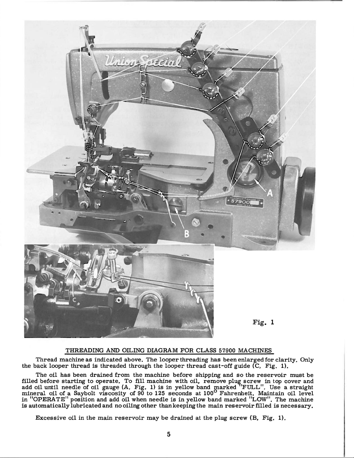
Fig.
1
Thread
the
back
looper
The
oil
filled
add
mineral
in
is
before
oil
until
oil
"OPERATE"
automatically
Excessive
THREADING AND OILING DIAGRAM
machine
has
starting
needle
of a Saybolt
as
thread
been
drained
to
of
position
lubricated
oil
in
the
indicated
is
threaded
operate.
oil
gauge
viscosity
and
add
and
main
above.
through
from
no
reservoir
the
To
(A,
of
oil
when
oiling
fill
Fig.
The
machine
machine
1)
90
to
needle
other
may
looper
the
is
125
than
be
looper
before
with
in
yellow
seconds
is
in
keeping
drained
FOR
CLASS 57900 MACHINES
threading
thread
oil,
yellow
cast-off
shipping
remove
band
at
100°
band
the
main
at
the
5
has
been
and
plu~
marked
Fahrenheit.
marked
reservoir
plug
enlarged
guide
so
'FULL".
screw
(C,
the
screw
"LOW".
filled
(B,
for
clarity.
Fig.
1).
reservoir
in
top
Use a straight
Maintain
The
is
necessary.
Fig.
1).
must
cover
oil
level
machine
Only
be
and
Page 6
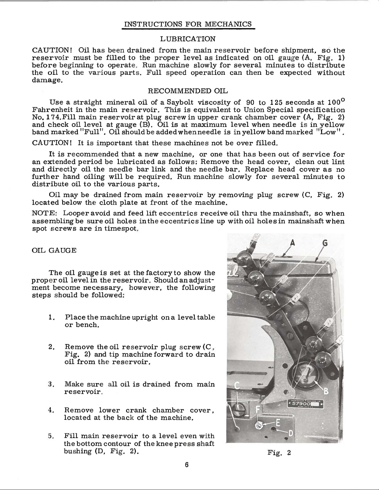
INSTRUCTIONS
LUBRICATION
FOR
MECHANICS
CAUTION!
reservo
before
the
damage.
Fahrenheit
No.
and
band
CAUTION!
an
and
further
distribute
located
NOTE: Looper
assembling
spot screws
beginning to
oil
Use
174.Fill
check
marked
It
is
extended period
directly
O
il
Oil has b
ir
must
to th
e var i
a s
traight
in the
mai
oil
"Full".
It
r e
commended
oil
hand
oil
may
be
below the
be sure
are
be
filled
operat
ous
mineral
main
n r e
servoir
level
is i
oiling
to
at
mportant
be
the nee
will
the
various part
drained
cloth
avoid and
oil
in
timespot
een
drained from the main
to
the proper
e.
Run
machine
part
s.
Full spe
RECOMMENDED
oil
of a Saybolt
reservoir.
gauge
Oil
should
that
lubricated
dle
be
from
plate
feed
hole
at
(B).
that
a new ma
bar
r equired. Run machine s
ma
at front
s in the ec
.
This
plug
be
lift
scr
Oil
is
added
the
se
as
follow
link and the needle
s.
in r e ser voir
of the m a
eccentrics r ece
centrics
level
ed
is
ew
in
at
whe
machin
chin
e,
rese
as
indicated
slowly
operation
viscosity
equivalent
upper cra
maximum
n ne
es
or
s:
Remove
line
for
OIL
edle
not
one that h
by
removing plug scr
chine.
ive
up
rvoir
several
can then
of
to Uni
nk
le
is in
be
the head cover,
bar.
lowly
oil
with
befor
on
oil gauge (A,
minutes
be
90
to
on
Special
cha
mber
vel
when
yellow
over
as been
Replace
thru the m a
oil
band marked "Low".
filled.
for several
holes
e shi
expect
125
seconds
cover
needle
out
he
ad
insh
in
pment,
Fig.
to dis
specification
of
clean
cover
ew (C,
aft,
mainshaft
tribute
ed
without
at
(A,
Fig.
is
in
yellow
service
out
minutes
Fig.
so
so
100°
lint
as
when
when
the
1)
2)
for
no
to
2)
OIL
GAUGE
The
oil
prop
er
oil
level
ment
steps should
become
1.
Place
or
2.
Remove
Fig.
oil
3. M
reservoir
4. Re
lo
ake sur
cated at the
gauge
be
bench.
from the
move lower
is
set
in
the
reservoir. Should
necessary,
followed
the
machine
the
oil res
2)
and
tip
reservoir.
e a
ll
.
at
the
however,
:
upright
ervoir
machine
oil
is
crank
ba ck
factory
forwa
drained
chamb
of the
to
show
an
the
followin
on a level
plug screw (C,
r d
from
er
machine.
adjust-
tabl
to
drain
ma
cover,
the
g
e
in
5.
Fill
main rese
the bottom contour
bushin
g (D, Fig. 2).
rvoir
to a lev
of the knee press sha
el even with
ft
6
Fig.
2
Page 7
OIL
GAUGE
6.
Loosen
or
"LOW".
7.
Tighten
8.
Add
"FULL".
(Continued)
lock
right
until
lock
oil
so
that
nut
the
nut
(E)
gauge
(E)
gauge
on
calibrating
needle
and
replace
needle
rests
rests
screw
in
plug
in
the
screw
the
(F),
and
middle
(C).
middle
turn
of
of
the
the
the
screw
yellow
yellow
to
band
band
the
left
marked
marked
ALIGNING
Align
and
test
plate
Machine
Style
57900
F-5
Fig.
THE
the
- 8
3
NEEDLE
needle
of
the
bar
right
Test
698
BAR
(A,
Fig.
gauge.
Plate
No.
AX-5-8
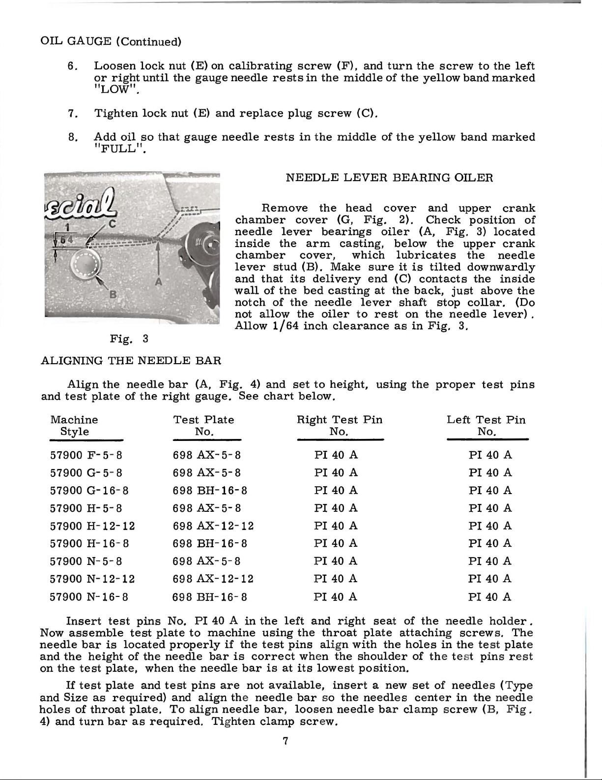
Remove
chamber
needle
inside
chamber
lever
and
wall
notch
not
Allow
See
that
of
allow
4)
chart
stud
of
1/64
and
NEEDLE
cover
lever
the
arm
cover,
(B).
its
delivery
the
bed
the
needle
the
inch
set
to
below.
Right
PI
LEVER
the
head
(G,
bearings
casting,
which
Make
casting
oiler
clearance
height,
Test
No.
40 A
Fig.
sure
end
lever
to
Pin
BEARING
cover
2).
oiler
below
lubricates
it
(C)
at
the
shaft
rest
on
as
using
and
Check
(A,
the
is
tilted
contacts
back,
stop
the
in
Fig.
the
proper
OILER
upper
position
Fig.
3)
upper
the
downwardly
the
just
above
collar.
needle
3.
test
Left
Test
No.
PI
crank
located
crank
needle
inside
lever)
pins
Pin
40 A
of
the
(Do
.
57900 G-5- 8
57900
G-16
57900 H-5-8
57900 H-12-12
57900
H-16
57900 N-5-8
57900
57900
N-12-12
N-16-8
Insert
assemble
Now
needle
and
on
and
holes
4)
the
the
If
Size
and
bar
height
test
test
of
turn
is
plate,
plate
as
throat
- 8
- 8
test
pins
test
located
of
the
when
and
required)
plate.
bar
as
698
698
698
698
698
698
698
698
No.
plate
to
properly
needle
the
test
and
To
align
required.
AX-5-8
BH-16-8
AX-5-8
AX-12-12
BH-16-
AX-5-8
AX-12-12
BH-16-
PI
40 A in
machine
if
bar
needle
pins
are
align the
needle
Tighten
8
8
the
is
bar
not
the
using
test
correct
is
at
available,
needle
bar,
clamp
7
PI
40 A
PI
40
A
PI
40
A
PI
40
A
PI
40 A
PI
40 A
PI
40 A
PI
40 A
left
and
right
the
throat
pins align with
wh
en
the
shoulder
its
lowest
position.
insert
bar
so
the
loosen
needle
screw.
seat
plate
the
a
needl
bar cla
of
the needle holder
attaching screw
holes
in
of the test pins r
new
set
of
needl
e s center
mp screw
PI
40 A
PI
40 A
PI
40 A
PI
40 A
PI
40
PI
40 A
PI
40
PI
40 A
the test
es (Typ
in
the
(B, F i
A
A
s.
Th
plat
est
needle
g.
.
e
e
e
Page 8
Check
Insert
plate
on
in
the
take-up
contacts
the
top
indicator
the
motions
ation
of
is
turned
reading
NOTE:
the
synchronization
the
pin,
throat
wire
the
edge
the
reading.
are
graduation
in
the
lower,
g
auge
which
needle
the
of
one
is
If
SYNCHRONIZING
is
included
plate
seat
hole
in
of
Turn
in
synchronization,
operating
this
No.
bed.
the
gauge
bar
and
the
on
the
direction,
shaft
21227 R is
of
the
looper
with
using
Turn
plate
the
handwheel
scale
will
have
not
the gauge,
the
throat
the
and
right
the
is
allowable.
the
to
available,
LOOPER
and
needle
plate
handwheel
set
the
end
of
in
point
looper
be
the
the
reverse
er
moved
synchronization
motions,
in
the
screws
in
operating
indicator
pointer
of
the indicator
If
the
drive
lever
to
the
AND
NEEDLE
using
back
hole
for
so
that
rests
direction
reading is
shaft
front.
MOTIONS
gauge
in
attaching.
the
direction
the
left
at
"O".
until
the
will
return
nigher
will
have
may
be
No. 21227 R
looper
Place
until
on
checked
the
end
of
Tighten
pin
again
to
the
the
to
be
the
scale
as
rocker.
shank
pin
the
pointer
the
contacts
same
moved
follows:
as
follows:
Place
in
the
set
reading. A vari-
when
to
of
the
looper
rests
screw
the
the
the
the
indicator
and
plate.
handwheel
rear.
gauge
rocker
against
note
If
the
If
Insert
er
and
of
right
respect
verse
and
ions
spect
.
005
needle
is
shaft
in
stud
(D,
rear
directly
forward
plate
back
er
using
the
stud, tig
screw
check
connecting
nut
turn
the
looper,
needle
direction
is
even
synchronize,
to
inch
to
turned
synchronizing
the
opposite
Moving
is
accomplished
Fig.
(away
support,
cover,
shaft,
the
looper
(D,
With
the
(A,
Fig.
the
handwheel
moving
(B).
to
the
looper
with
the
looper
is
allowable.
the
point
in
the
of
5)
of
the
from
on
the
(toward
then, a light
toward
looper
drive
hten
the
Fig.
the
looper
location
rod
bearing,
6)
front
looper
Note
until
the
the
left
the
height
point
of
the
operating
stud
direction
the
looper
looper
operato
stud,
is
operator),
oil
reservoir
the
operator,
drive
lever
looper
5).
at
of
and
place
in
to
the
the
height
point,
looper
side
If
looper
(C,
acts
as
follows:
drive
r ), a
all
tap
lever
rocker
the
the
using
hole
(A,
left
then
of
of
the
be
the
distance
Fig.
the
drive
light
that
remove
top
on
is
to
extreme
center
gauge
in
Fig.
is
of
point
the
is
lever
is
the
all
take
shaft
lever
operating
will
direction,
drive
5)
direction
even
the
eye
turn
handwheel
again
right
eye
of
the
same.
greatest
move
5)
to
reverse.
lever
Loosen
(E).
tap
with a small
required.
the
cover
looper
that
up
the
and
on
right
line
of
No.
gauge
The
looper
screw
quired. Tig
be
looper
be 4 1/16
of
its
in the
until
with
the
of
the
moves
needle.
the
needle
A
from
the
when
the
the
rear.
shaft
synchronizing
the
To
To
cloth
and
oil
drive
is
required.
end
its
synchronizing
the
end
the right
21227
over
threaded
left
end
rocker
(C, Fig. 6)
checked
rocker cone
travel.
looper
variation
looper
clamp
move
plate,
play
shaft,
of
CX.
inches
rock-
the
point
left
side
needle
If
move
lever
hten
with a scale.
with
in
the
to
the
the
mot-
with
eye
of
the
pulley
drive
Moving
screw
stud
hammer,
stud
throat
reservoir
rockThen,
between
using
its
travel,
looper
Remove
stud.
of
the
cone
and
clamp
(Fi
of
re-
left
re-
of
the
it
to
gauge
(B).
reposition
screw.
and
the
g.
6),
should
If
adjustment
The
distance
centerline
when
locate
If
gauge
looper
the
Fig.
against
is
necessary,
looper
is
not
between
of
the
is
4
the
drive lever
available,
the
looper
at
the
extreme rig
right
loosen
center
lever
side
of
the
(D)
setting can
line
stud
the
clamp
as
re-
of
the
should
ht
end
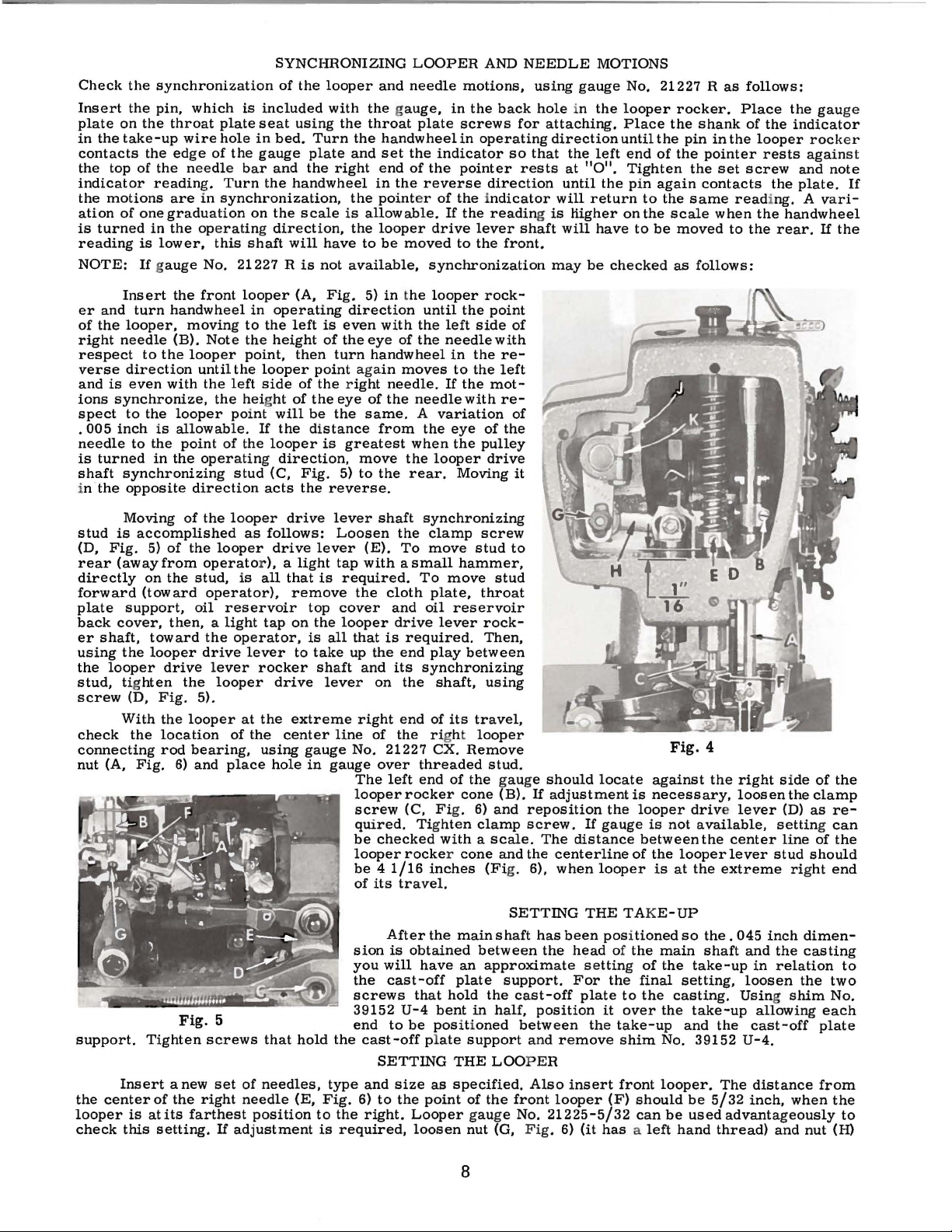
SETTING
After
the
main
shaft
has
been
the
position
between
and
remove
Also
looper
21225-5/32
Fig.
6)
support.
the
center
looper
check
Tighten
Insert
is
at
this
Fig.
anew
of
the
its
farthest
setting.
5
screws
set
right
If
that
hold
of
needles,
needle
adjustment
(E,
position
the
type
Fig.
to
the
is
required,
sion
you
the
screws
39152
end
6)
is
obtained
will
have
cast-off
that
bent
be
positioned
as
point
Looper
loosen
hold
U-4
to
cast-off plate
SETTING
and
size
to
the
right.
between
an
approximate
plate
THE
specified.
support.
the
in
half,
support
LOOPER
of
the
gauge
nut
(G,
cast-off
front
No.
8
THE TAK
positioned
head
of
setting
For
the
plate
it
the
insert
(F)
(it
has a left
E-UP
the
of
final
to
the
over
take-up
shim
front
should
can
so
main
the
take-up
setting,
casting.
the
take-up
and
No.
39152
looper.
be
be
used
hand
the.
045
shaft
the
The
5/32
thread)
inch
and
in
loosen
Using shim
allowing
cast-off
U-4.
distance
inch,
advantageously
dimen-
the
casting
relation
the
when
and
nut
to
two
No.
each
plate
from
the
to
(H)
Page 9
on
connecting
5/32
the
left
ers
at
to
get
inch
ball
front
the
rod
dimension.
joint
proper
is
or
back
in-line-of-feed
(J),
turn
Retighten
in
vertical
Fig.
of
the
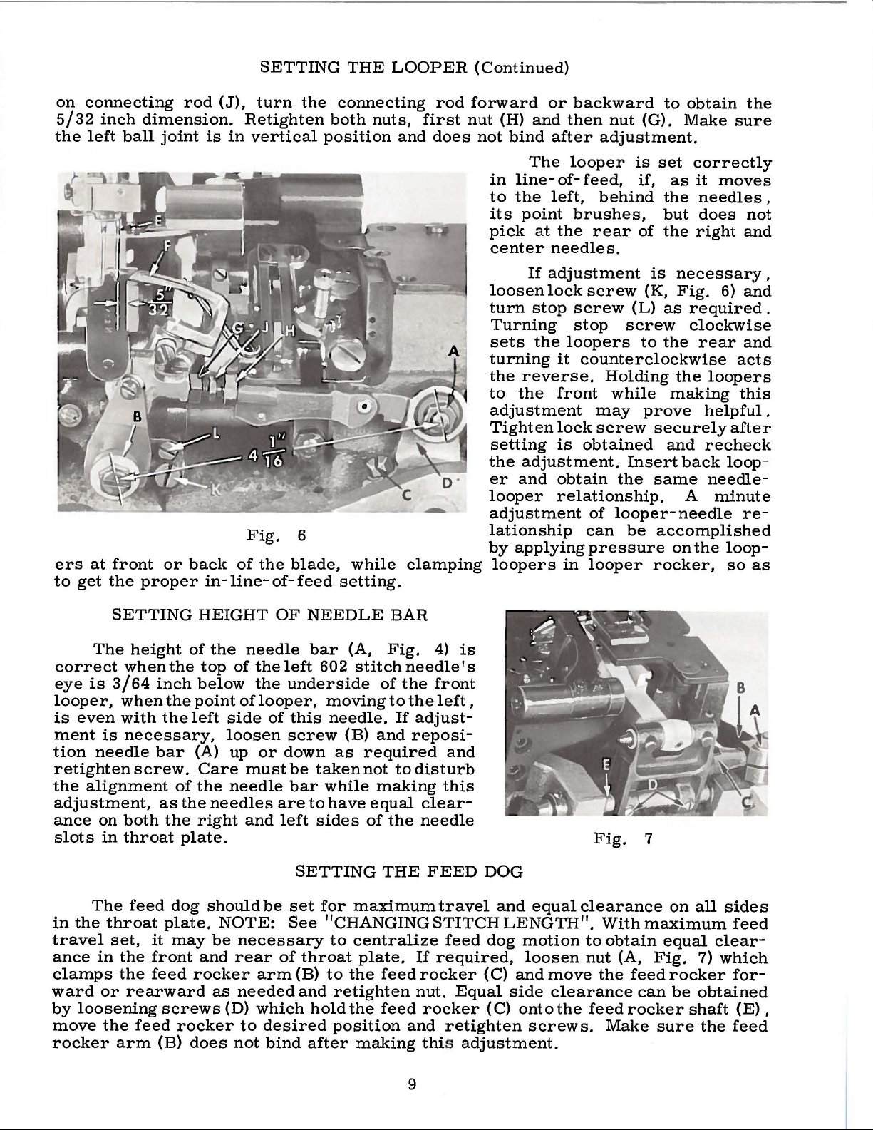
SETTING
the
position
6
blade,
THE
LOOPER
connecting
both
nuts,
and
while
setting.
rod
first
nut
does
clamping
(Continued)
forward
(H)
not
or
and
bind
The
in
line-
to
the
its
point
pick
at
center
If
adjustment
loosen
turn
lock
stop
Turning
sets
the
turning
the
reverse.
to
the
adjustment
Tighten
setting
the
adjustment.
er
and
looper
adjustment
lationship
by
applying
loopers
backward
then
nut
(G).
after
left,
looper
of-
feed,
adjustment.
is
if,
behind
brushes,
the
rear
of
needles.
screw
screw
stop
loopers
it
counterclockwise
(K,
(L)
screw
to
Holding
front
lock
is
while
may
screw
obtained
prove
Insert
obtain
the
relationship.
of
looper-
can
be
pressure
in
looper
to
obtain
Make
set
as
the
but
the
is
necessary
Fig.
as
required.
sure
correctly
it
moves
needles
does
right
6)
clockwise
the
rear
acts
the
loopers
making
this
helpful.
securely
and
back
same
A
after
recheck
loop
needle-
minute
needle
accomplished
on
the
loop-
rocker,
so
the
,
not
and
,
and
and
-
re-
as
SETTING
The
height
correct
eye
looper,
is
even
ment
tion
when
is
3/64
when
with
is
necessary,
needle
retighten
the
alignment
adjustment,
ance
slots
in
travel
ance
clamps
ward
by
move
rocker
on
both
in
throat
The
feed
the
throat
set,
in
the
the
or
rearward
loosening
the
arm
the
inch
the
the
bar
screw.
as
the
dog
plate.
it
may
front
feed
screws
feed
(B)
HEIGHT
of
the
top
below
point
left
(A) up
Care
of
the
the
needles
right
plate.
should
be
and
rocker
as
rocker
does
needle
of
the
the
of
looper,
side
loosen
or
must
needle
and
be
NOTE:
necessary
rear
arm
needed
(D)
which
to
desired
not
OF
NEEDLE
bar
left
underside
of
this
screw
down
be
bar
are
to
left
SETTING
set
See
of
throat
(B)
and
hold
bind
after
BAR
(A,
602
moving
needle.
(B)
as
taken
while
have
sides
for
maximum
Fig.
stitch
of
to
and
required
not
making
equal
of
the
THE
4)
needle's
the
front
the
left,
If
adjust-
reposi-
to
disturb
clear-
needle
FEED
is
and
this
travel
DOG
and
equal
"CHANGINGSTITCHLENGTH".
to
centralize
plate.
to
the
retighten
the
position
making
feed
feed
feed
dog
If
required,
rocker
nut.
rocker
and
(C)
Equal
(C)
retighten
side
this adjustment.
motion
loosen
and
move
onto
screws.
Fig.
clearance
With
to
obtain
nut
the
clearance
the
feed
Make
7
maximum
(A,
Fig.
feed
can
rocker
sure
on
all
equal
7)
rocker
be
obtained
shaft
clear-
which
the
sides
feed
for-
(E),
feed
9
Page 10
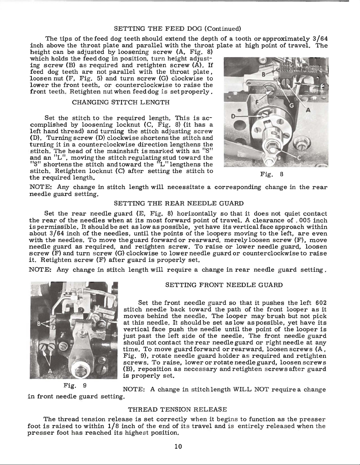
The
tips
of
the
feed
inch
height
which
ing
screw
feed
loosen
lower
above
dog
can
holds
teeth
nut
the
front
the
throat
be
adjusted
the
feed
(B)
as
are
(F, Fig.
teeth,
requ
front teeth. Retighten
dog
plate
by
dog
in
ired and
not
parallel
5)
and
or
nut
SETTING
teeth
and
loosenin
THE FEED DOG
should
parallel
g s
position, turn
retighten
with
turn
screw
counterclockwi
when
feed
dog
extend
with
crew
the
(G)
se
is
the
(A, Fig.
hei
ght
screw
throat
clockw
to
set
properly.
the
throat
adjust-
(A).
plate,
ise
raise
(Continued)
depth
of
plate
8)
If
to
the
a t
ooth
at
or
high
approximately
point
of
travel.
3/64
The
Set
complished
left
hand
(D).
Turning screw
turning it
s
titch.
and
11811
stitch.
the
NOTE:
needle
The
an 11L
shortens
Retighten
required
Any
guard
Set
the
rear
is
permissible.
about
with
needle
screw
it.
NOTE:
3/64
the
guard
(F)
Retighten
Any
CHANGING
the
stitch
by
thread)
to
loosening
and
STITCH
the
required
locknut
turning
(D)
clockwise shortens
in a counterclockwise
11
,
head
of
the
moving the
the
stitch
locknut
mainshaft
stitch
and
(C)
length.
change
in
stitch
setting.
SETTING
the
rear
of
the
inch
needles.
and
needle
needles
It
should
of
the
To
move
as
required,
turn screw
screw
change
(F)
in
guard
when
be
needles,
(G)
after
stitch
the
regula
toward
aft
er
length
(E, Fig.
at
its
set
as
until
the
guard
and ret
clockwise
guard
length
LENGTH
len
gth. Th
(C,
Fig.
stitch
direction
is
marked
tin~
the
' L
setting
will
THE
most
low
as
possible,
the
forward
ighten
to
is
properly
will
is is
8)
(it
adjusting
the
stitch
lengthens
with
stud
toward
11
lengthens the
the
necessitate
REAR
8)
horizontally
forward
points
or
screw.
lower
ac-
has
scre
w
and
the
an 11S
the
stitch
to
a
NEEDLE
point
yet
have
of the loopers moving
rearward, merely
To
rai
needle guard
set.
require a change
a
11
corresponding
GUARD
so
that
of tra
vel. A clearance
its
vertical
se
or
lower
or
counterclockwise
in
rear
Fig.
change
it
does
not
face
approach
to
the
loosen
screw
needle
needle guard
8
in
the
quiet
contact
of . 005 inch
within
left, are
(F),
guard,
loosen
to
setting
rear
even
move
raise
.
in
foot
pr
ess
front
The
i s r ais
er
Fig.
9
needle guard
thread
foot has
ed
tens
to
within
reached
setting.
ion
release
1/8
stitch
moves
at
vertical
just
should
time.
Fig.
screws.
(B),
is
NOTE:
inch
its
highe
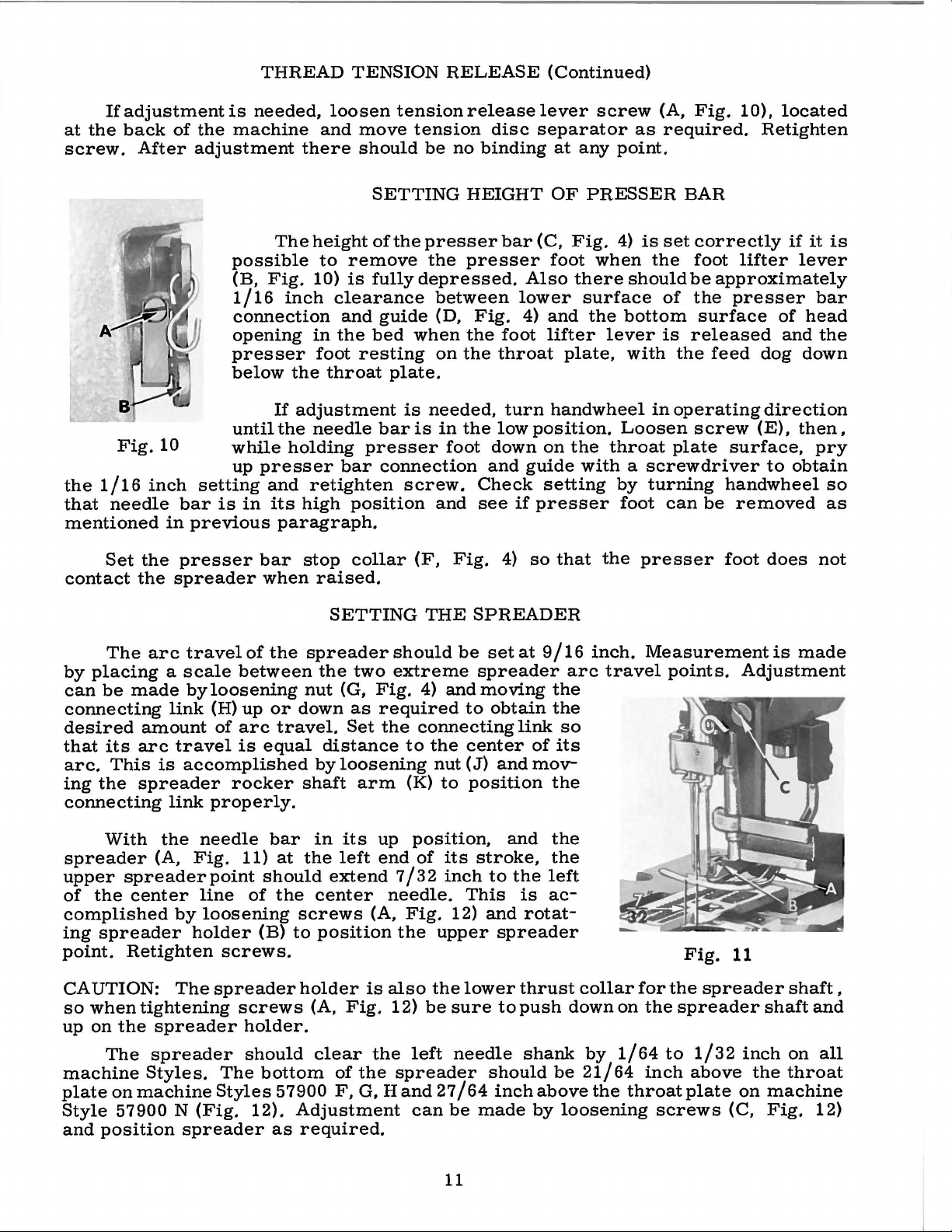
Set
the
needle
behind
this
needle.
face
past
not
To
9),
rotate
To
reposition
properly
A
THREAD
is
set
of
the
st
position
SETTING
front
back
the
It
push
the
left
contact
move
guard
needle
raise,
as
set.
change
TENSION
correctly
end
of its
10
FRONT
needle guard
toward
needle.
should
side
the
the
be
needle
of
rear
the
forward
guard
lower
or
necessary
in stitch
RELEASE
when
travel
.
the
The
set
needle.
needle
or
holder
rotate
and
length
it
begi
and
NEEDLE
so
that
path
looper
as
low
until
guard
rearward,
needle
of
may
as
the
The
as
required
GUARD
it
pushes
the
front
brush
possible,
point
front
or
r i
loosen
guard,
retighten screws
WILL
ns
is
NOT
to
function
entirely
relea
the
left
602
of
looper
but
yet
the
as
not
have
looper
pick
its
is
needle guard
ght
needle
and
at
screws
retighten
any
(A,
loosen screws
after
gua
rd
require a change
as
the
presser
sed
when
the
it
Page 11
If
at
the
screw.
adjustment
back
of
After
the
adjustment
THREAD
is
needed,
machine
loosen
and
there
TENSION
tension
move
should
tension
be
RELEASE
release
disc
no
binding
(Continued)
lever
screw
separator
at
any
point.
(A,
as
required.
Fig.
10),
located
Retighten
Fig.
the
1/16
that
needle
mentioned
Set
the
contact
the
10
inch
bar
in
presser
spreader
possible
(B,
1/16
connection
opening
presser
below
until
while
up
setting
is
in
previous
The
height
to
Fig.
10)
inch
in
foot
the
If
adjustment
the
needle
holding
presser
and
retighten
its
high
paragraph.
bar
stop
when
raised.
SETTING
of
the
remove
is
fully
clearance
and
guide
the
bed
resting
throat
plate.
bar
presser
bar
connection
position
collar
SETTING
HEIGHT
presser
the
presser
depressed.
between
(D,
when
is
is
the
on
the
needed,
in
the
foot
screw.
and
(F,
Fig.
THE
OF
bar
(C,
foot
Also
lower
Fig.
4)
foot
throat
turn
low
down
and
Check
see
if
4)
and
lifter
plate,
handwheel
position.
on
guide
setting
presser
so
that
SPREADER
PRESSER
Fig.
4)
when
there
should
surface
the
bottom
lever
with
Loosen
the
throat
is
set
the
of
is
the
in
operating
plate
BAR
correctly
foot
be
the
surface
released
feed
screw
with a screwdriver
by
turning
foot
can
be
the
presser
if
it
lifter
lever
approximately
presser
dog
of
and
bar
head
the
down
direction
(E),
then,
surface,
to
handwheel
removed
foot
does
pry
obtain
so
as
not
is
The
arc
by
placing a scale
can
be
made
connecting
desired
that
arc.
ing
its
This
the
amount
arc
spreader
connecting
With
spreader
upper
of
the
(A,
spreader
center
complished
ing
spreader
point.
Retighten
CAUTION:
so
when
up
on
machine
plate
Style
and
tightening
the
spreader
The
spreader
Styles.
on
machine
57900 N (Fig.
position
travel
between
by
loosening
link
(H)
of
arc
travel
is
accomplished
is
rocker
link
properly.
the
needle
Fig.
point
line
by
loosening
holder
screws.
The
spreader
screws
The
Styles
spreader
of
the
up
or
travel.
equal
bar
11)
at
should
of
the
(B)
to
holder.
should
bottom
57900
12).
as
spreader
the
two
nut
(G,
Fig.
down
as
Set
required
the
distance
by
loosening
shaft
the
in
arm
its
left
up
end
extend
center
screws
(A,
position
holder
(A,
clear
Fig.
of
F,
is
the
the
G,
Adjustment
required.
should
extreme
4)
and
connecting
to
the
nut
(K)
to
position,
of
its
7/3 2 inch
needle.
Fig.
the
upper
also
the
12)
be
left
spreader
Hand
27/64
can
be
set
spreader
moving
to
obtain
center
(J)
position
stroke,
to
This
12)
and
lower
sure
needle
should
be
made
at
9/16
the
the
link
of
its
and
mov-
the
and
the
the
the
left
is
ac-
rotat-
spreader
thrust
to
push
shank
be
inch
above
by
inch.
arc
travel
so
collar
down
by
on
1/64
21/64
the
throat
loosening
Measurement
points.
for
the
inch
Fig.
the
spreader
to
11
spreader
1/32
above
plate
screws
(C,
is
made
Adjustment
shaft
shaft
inch
the
on
and
on
all
throat
machine
Fig.
12)
,
11
Page 12
The
needle
can
be
ing
the
left
edge
by
approximately
accomplished
guide
as
necessary.
of
the
by
SETTING
SJ?reader
3f32
loosening
inchand
THE
thread
screws
SPREADER
guide
be
kept
close
(C)
and
(Continued)
(B,
Fig.
to
the
mov-
11)
top
should
of
the
clear
spreader.
the
right
This
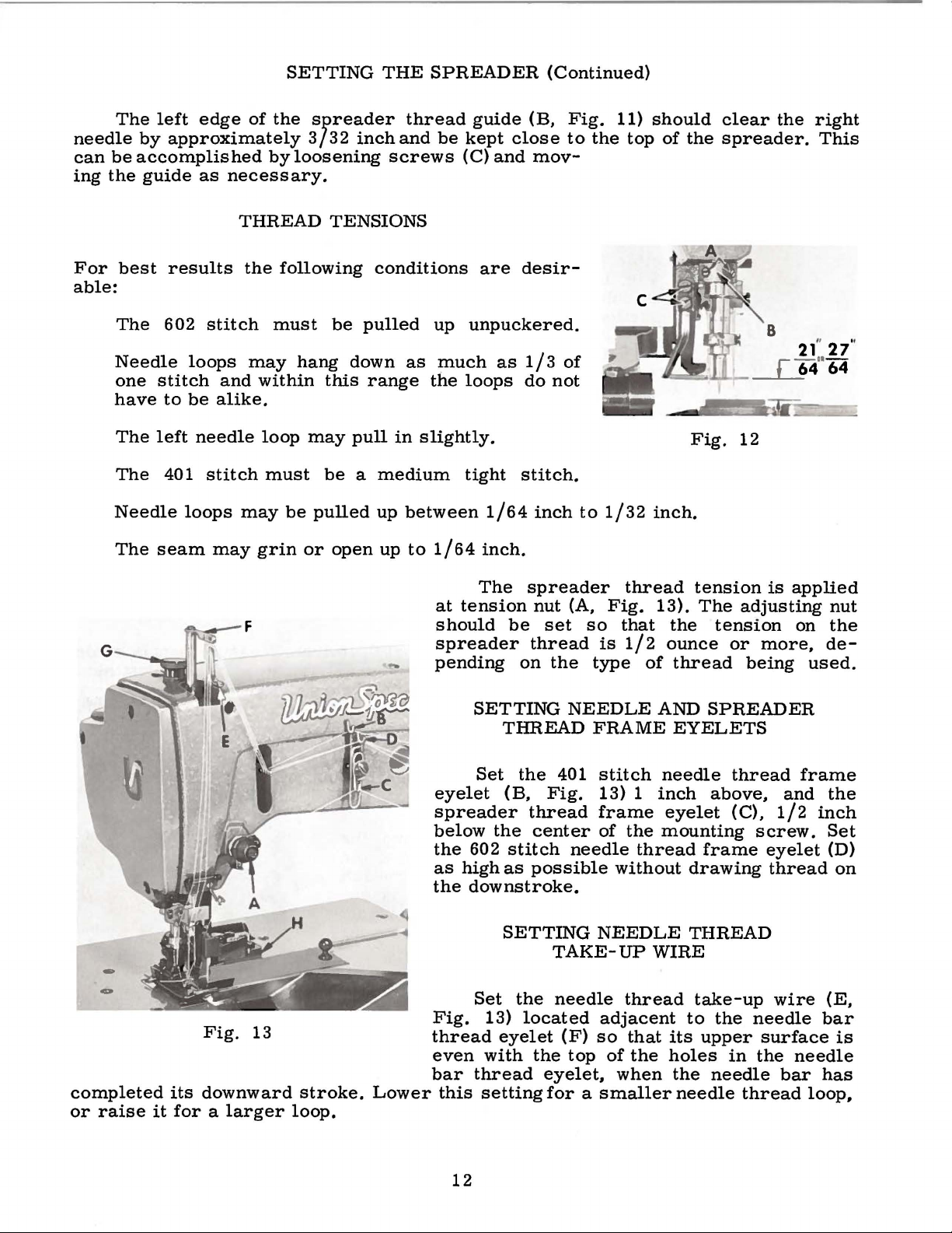
For
able:
best
The
Needle
one
stitch
have
The
left
The
Needle
The
seam
results
602
loops
to
be
needle
401
loops
THREAD
the
stitch
and
alike.
stitch
may
may
following
must
may
within
loop
must
be
grin
TENSIONS
conditions
be
pulled
hang
down
this
range
may
pull
be a medium
pulled
or
up
open
as
in
between
up
to
up
unpuckered.
much
the
loops
slightly.
tight
1/64
The
at
tension
should
spreader
pending
are
as
1/64
inch.
be
desir-
1/3
of
do
not
stitch.
inch
spreader
nut
(A,
set
thread
on
the
to
so
type
1/32
Fig.
is
inch.
thread
13).
that
1/2
of
Fig.
tension
The
the
ounce
thread
12
adjusting
tension
or
more,
being
8
is
applied
on
used.
nut
the
de-
-
-
completed
or
raise
Fig.
its
downward
it
for a larger
13
stroke.
loop.
Lower
SETTING
Set
eyelet
spreader
below
the
602
as
high
the
downstroke.
Set
Fig.
thread
even
bar
this
13)
with
thread
setting
THREAD
the
401
(B,
Fig.
thread
the
center
stitch
as
possible
SETTING
TAKE-UP
the
needle
located
eyelet
the
eyelet,
for a smaller
NEEDLE
FRAME
stitch
13) 1 inch
frame
of
needle
without
NEEDLE
adjacent
(F)
so
top
of
when
AND
needle
eyelet
the
mounting
thread
WIRE
thread
that
the
SPREADER
EYELETS
thread
above,
(C),
frame
drawing
THREAD
take-up
to
the
its
upper
holes
the
needle
in
needle
thread
and
1/2
screw.
eyelet
thread
wire
needle
surface
the
needle
bar
frame
the
inch
Set
(D)
on
(E,
bar
is
has
loop,
12
Page 13

PRESSER
FOOT
PRESSURE
Regulate
pressure
on
the
of
the
machine.
reverse.
The
throat
on
fabric.
cutting
plate
the
the
This
(B).
presser
presser
is
the
Turning
edge
of
This
can
spring
foot
knurled
it
ADJUSTING
the
be
Fig.
regulating
to
clockwise
lower
accomplishedby
14
feed
screw,
knife
screw
the
work
located
increases
TRIMMER
(A,
Fig.
loosening
(G,
Fig.
uniformly
directly
the
pressure,
MECHANISM
14)
should
screw
13)
so
that
when a slight
behind
down
screw.
lower
with
dle.
by
screw
operator
and
operator
desired
obtained,
Fig.
lower
1
be
and
clockwise
wise
ed,
the
crease
en
the
counterclockwise
be
set
level
(C),
move
as
required
The
knife
the
center
This
loosening
(A,
to
turning
acts
position
14).
The
knife
degree.
made
screws
by
turning
until
turning
opposite
the
it
exerts
tension
needle
can
retighten
should
This
loosening
and
the 1 degree
shear
(E).
bar
with
the
lower
and
trimming
should
of
the
be
accomplished
screw
Fig.
15)
move
knife
it
away
the
reverse.
of
knife
shear
be
adjustment
screw
screws
direction
(F)
screw
angle. Retight-
angle
(F)
only
enough
is
placed
in
the
acts
top
knife
retighten
edge
be
aligned
right
(D),
toward
to
the
from
has
screw
set
at
screws
counter-
(G)
clock-
is
obtain-
& (G)
will
head
the
of
the
up
or
nee-
turn
the
left
the
When
been
(D,
of
the
about
can
(E)
in
de-
of
The
upper
of
its
blade.
be
accomplished
tioning
by
has
rearward
loosen
then
Allen
NOTE:
force
(in
screwdriver,
of
noted.
ble,
of
loosening
been
inches
torque
obtained,
lock
turn
head
Upper
should
Torque
(in
pounds)
will
All
straps
All
unless
knife
Positioning
knife
upward
screw
repositioning
nuts
eccentric
screws
bear
TORQUE
(measured
or
feet).
etc.
tighten
and
other
otherwise
by
(K)
and
knife
against
applied
Many
nuts,
should
loosening
(J).
retighten
This
eccentrics
be
set
to
of
knife
or
downward
When
of
upper
and
loosen
pin
(M)
lock
lever
the
bolts,
noted.
thrust
upper
REQUIREMENTS
in
through a distance
is
accomplished
ofthese
part
to
screw
desired
screws.
knife
Allen
as
required.
nuts.
bracket
knife
inch-pounds)
devices
to
the
should
screws,
trim
the
left
(H,
Fig.
can
be
position
Should
become
head
lever.
correct
be
etc.,
the
full
or
right
14).
accomplished
of
forward
necessary,
screws
Retighten
(H,
Fig.
is a rotating
by a lever
by a wrench,
are
available,
amount
tightened
should
length
can
Posi-
knife
or
(L),
13)
and
to
19-21
be
tightened
which
no
tighter.
inch-pounds,
when
by
set
hand
at
as
Fig.
the
unless
tightly
15
proper
otherwise
as
amount
possi-
The
screws
requiring a specific
torque,
will
be
indicated
13
on
the
picture
plates.
Page 14

'
)
~-
CAUTION!
Fill
oil
before
Machine
drained
shipping.
rese.rvolr
startmg.
before
has
.
been
14
Page 15

MAIN
FRAME,
CAST-OFF
PLATE
AND
MISCELLANEOUS COVERS
Ref.
No.
1
2
3
4
5
6
7
8
9
10
11
12
13
14
15
16
17
18 51282 AE
19
20
21
22
23
24
25
26
27
28
29
30
31
32
33
34 22585 A
35
35A 57944
36
37
38
39
40
41
42
43
44
45
46
47
48
49
50
51
52
53
54 51959 B
55
56
57
58 57857
59
60
61
62
63
64
65
66
67
Part
No.
22829
56382
56382 F
56382 E
56382 p
57831
57882 B
57882
35731 A
57844
57892 A
57892
57892 B
51758
21375AV
22829
56391
51959 D
51959 K
51492
51459 A
22569 D
57804
52958 G
52958
57944 B
57944 A
J
56382 K
22848
56382 L
22548
56382 D
56382 B
56382 M
22733 E
22541 c
56382
22539
52882
22894 E
57970 A
22539 G
56382 s
22564 B
22569 c
22733 c
22513
57844 A
80665 F
22848
22889 A
90
357
90
95
20
539
98 A
52 A
28
87
u
HT2 C
605
A
c
s
y
C-5
Description
Screw---------------------------------------------------------------
Looper
Gasket--------------------------------------------------------------
Oil
Screw
Gasket--------------------------------------------------------------
Screw
Crank
Gasket--------------------------------------------------------------
Upper
Gasket
Oil
Screw---------------------------------------------------------------
Gasket--------------------------------------------------------------
Screw
Plug
Baffle
Needle
Screw---------------------------------------------------------------
Needle
Plug
Oil
Screw--------------------------------------------------------------Screw---------------------------------------------------------------
Spring
Presser
Screw
Gasket--------------------------------------------------------------
Screw---------------------------------------------------------------
Head
Screw---------------------------------------------------------------
Presser
Screw--------------------------------------------------------------Spreader
Spreader
Screw--------------------------------------------------------------Spreader
Spreader
Spreader
Spreader
Spreader
Screw--------------------------------------------------------------Washer
Spreader
Needle
Adaptor
Belt
Screw--------------------------------------------------------------Screw---------------------------------------------------------------
Looper
Looper
Tension
TensionSpring-------------------------------------------------------
Tension
Tension
Looper
Screw--------------------------------------------------------------Cast-off
Cast-off
Screw--------------------------------------------------------------Looper
Screw--------------------------------------------------------------Looper
Spreader
Screw---------------------------------------------------------------
Drive
Reservoir
--------------------------------------------------------------
--------------------------------------------------------------
Chamber
Crank
Filler
--------------------------------------------------------------
Screw----------------------------------------------------------
Plate
Lever
Thread
Screw----------------------------------------------------------
Drip
--------------------------------------------------------------
--------------------------------------------------------------
Cover----------------------------------------------------------
Plug
Thread
Guard----------------------------------------------------------
Thread
Thread
Thread
Frame
Thread
Thread
Screw-----------------------------------------------------------
Shaft
Reservoir
Back
Cover
Cover,
Chamber
------------------------------------------------------------Plug
Screw
--------------------------------------------------------Bearing
Pull-off
Plate-------------------------------------------------------
Bar
Connection Guide
Screw------------------------------------------------------
Bar
Connection Guide
Thread
Thread
Thread
Thread
Thread
Thread
Thread
------------------------------------------------------------Thread
Plug
Nut
Disc--------------------------------------------------------
Post--------------------------------------------------------
Plate
Plate,
and
Guide,
Guide,
Eyelet----------------------------------------------Tension
Tension
Tension
Tension
Frame
Frame
Screw
Eyelet
Guard-------------------------------------------------
---------------------------------------------------------
Guide-------------------------------------------------
Support
marked
Thread
Cast-off
Needle
Eyelet
lower-----------------------------------------
Cover
------------------------------------------------
Oiler-------------------------------------------
Wire------------------------------------------
Eyelet------------------------------------------
--------------------------------------------------
-------------------------
-----------------------------------------------"B"
Eyelet------------------------------------------
Guide
Thread
---------------------------------------------------
Cover-----------------------------------
--------------------------------------------
-----------------------------------------
Plate,
Plate,
for
all
for
Eyelet----------------------------------------
Styles except 57900
Style 57900
Post----------------------------------------Disc----------------------------------------Spring---------------------------------------
Post
Nut-------------------------------------
-------------------------------------------
Eyelet-----------------------------------
Guide-------------------------------------
rear
-----------------------------
front
-----------------------------
N,
All
N,
Gauges-------------------
-----------------------
1
All
Gauges---------
Amt.
Req.
2
1
1
1
9
1
4
1
1
1
1
1
4
1
2
1
1
1
2
1
1
1
1
1
1
1
2
1
3
1
1
2
1
2
1
1
1
1
1
2
1
1
1
1
1
2
1
1
2
3
1
1
1
1
2
1
1
2
1
1
2
1
1
1
1
1
1
1
15
Page 16

•t·
on
Glue
t
he
·
pos
m lf
1 W
o
er
ha
1 1
only
·
16
Page 17

MAIN
FRAME,
BUSIDNGS,
OIL
GAUGE
AND
MISCELLANEOUS
OILING
PARTS
Ref.
No.
-
1
2
3
4
5
6
7
8
9
10
11
12
13
14
15
16
17
18
19
20
21
22
23
24
25
26
27
28
29
30
31
32
33
34
35
36
37
38
39
40
41
42
43
Part
No.
56393
666-214
57849
52883
21657
56390
57890
22569
63494
63494
63494
660-455
56394
660-221
61256
11635
56394
660-219
56394
27-527
61494
604
22539
56390
666-232
56390
52942
50-895
52942
52942
56393
666-259
56390
57836
51257
57846
57954
56393
57849
51154
56393
57893
666-214
s
R
X
E
B
K
F
G
B
G
B
A
c
G
R
A
D
X
w
y
p
B
AA
R
E
Q
A
Blk.
Blk.
Description
Base
Spreader
Presser
Release
Bushing
Crankshaft
Screw--------------------------------------------
Oil
Oil
Oil
Washer-------------------------------------------
Nut
Oil
Oil
Washer
Collar--------------------------------------------
Plug
Main
Felt
Main
Looper
Looper
Looper
Synchronizing
Base
Felt---------------------------------------------Main
Feed
Presser
Spreader
Needle
Oil
Spreader
Needle
Base
Head
Oil
Pump
Intake
Rocker
Foot
Lever
Housing
Gauge
Nut
Spring
''O''
Gauge
Retaining
----------------------------------------------
Gauge
Pin
Gauge
Screw----------------------------------------
Screw
Washer
Shaft
Attraction
Felt,
Oil
Intake
Assembly
------------------------------------------
Ring
Connecting
Adjusting
------------------------------------------
Float
------------------------------------------
Shaft
Shaft
Drive
Rocker
Drive
Felt,
Rocker
Bar
Holder
Bar
Rocker
Bar
Pump
Assembly---------------------------
Felt------------------------------------
Shaft
Lifter
Bushing-----------------------------
Gasket----------------------------
Bushing
Washer--------------------------------
-------------------------------------
Ring
Lever
---------------------------------------
Bushing,
--------------------------------------
Bushing,
Lever
Shaft
Lever
Stud
front-----------------------------------
Bushing,
Shaft
Bushing,
Carrier
Bushing,
Felt---------------------------------
Shaft
Bushing,
rear-----------------------------------
Assembly---------------------------
Felt -----------------------------------
Bushing----------------------
Lever
Housing
-------------------------------
Rod
------
Shaft
right--------------------------
middle
Shaft
Bushing
Shaft
--------------------------------
left----------------------------
Bushing-------------------------
lower--------------------··----
upper-------------------------
Bushing------------------
------------------------
--------------------------
------
--------------------------
Assembly--------------------
Bushing,
Bushing,
lower------------------------
Bushing
Bushing-----------------------
-------------------
------------------------
-----------------------
-------------------
rear------------front-------------
--
Amt.
Req.
1
1
1
1
1
1
1
3
1
1
1
1
1
1
2
1
1
1
1
1
1
1
1
1
1
1
1
2
1
1
1
1
1
2
1
1
1
1
1
1
1
1
1
17
Page 18

2
NOTE:
Cut-out
58
and
when
of Ref.
59
asse
to
be
No.I
up
I
18
Page 19

CRANKSHAFT,
NEEDLE
LEVER,
NEEDLE
BAR AND
LOOPER
DRIVING
PARTS
He
10
11
12
13
14
15
16
17
18
19
20
21
22
23
24
25
26
27
28
29
30
31
32
33
34
35
36
37
38
39
40
41
42
43
44
45
46
47
48
49
50
51
52
53
54
55
56
57
58
59
60
61
62
63
64
65
66
67
68
69
70
71
72
73
f.
No.
1
2
3
4
5
6
7
8
9
Part
No.
57842
A
57918-5-8
88
B
22738
F
57942
77
89
52917-8
50
J-16
27-435
56958
A
22768
22586
H
F
51250
51250
D
660-212
51150
29348
y
56315
77
56354
A
56354
22562 A
22564
51054
666-149
56350
A
56958
22768
660-212
56316
29066 R
22559 G
51216
N
51216
p
52917-12
22716
52931
57918-16-8
89
28
88 B
57942
A
22738 F
57847
95
57821 A
56321 A
22894
AB
57821
61321 L
22574
660-202
29476
MN
29476 MR
51216 M
56316
c
12934
A
52943 L
22894
X
29105 AG
22559 A
56343
E
c
56343
22587 K
56343
D
22894
X
52942
A
660-202
56342
B
57942
B
CL21
Description
Spreader
Needle
Needle
for
Elk.
Needle
Needle
Screw
Screw
Gasket
VVasher-------------------------------------------------------------------Oil
Needle
Needle
Needle
Screw
Oil
Needle
Needle
VVasher-------------------------------------------------------------------Nut
Needle
Screw,
Styles
Needle
gauge,
Needle
for
Thrust
Handwheel
"O"
Crankshaft
Crankshaft
Connecting
Nut-----------------------------------------------------------------------
Head
Base
Looper
Looper
Looper
Looper
"O"
Oil
Looper
Oil
Thread
Bar
Set
Screw--------------------------------------------------------------
Screw
Needle
Screw
Spot
Screw------------------------,-------------------------------------
Bar,
No.
16-8
Needle
Bar
Bar
---------------------------------------------------------------------
---------------------------------------------------------------------
--------------------------------------------------------------------
Seal
Ring---------------------------------------------------------------
Lever
Lever
Needle
Screw
Needle
Needle
Screw
Screw
Link
Pin---------------------------------------------------------------
Fell
Needle
Lever
---------------------------------------------------------------------
Seal
Ring---------------------------------------------------------------
Lever
Lever
Screw
-----------------------------------------------------------------------
Bar,
for
57900
Stop
Styles
Bar
No.
12-12
Spot
Screw-------------------------------------------------------------
Screw
Set
Screw--------------------------------------------------------------
Needle
Screw
Collar
Screw----------------------------------------------------------------~
Pulley-----------------------------------------------------------------
Screw
Handwheel
Retaining
Screw
Ring-------------------------------------------------------------------
Needle
Oil
Pump
Oil
Pump
Drive
Screw----------------------------------------------------------------
Drive
Bearing
OilSplasher
Ball
Joint
Bearing
Drive
Screw
Drive
Ring
------------------------------------------------------------------
Seal
Collar
Drive
VVick-------------------------------------------------------------------
Eyelet
Head,
----------------------------------------------------------------Thread
-----------------------------------------------------------------
marked
gauge,
Stop
Pin-------------------------------------------------------Eyelet
Thread
Thrust
Assembly-----------------------------------------------------
Lever----------------------------------------------------------
----------------------------------------------------------------Bar
Link--------------------------------------------------------
Bar
Connection--------------------------------------------------
-------------------------------------------------------------
-----------------
VVick----------------------------------------------------------
Lever
Thread
Connecting
Connecting
-----------------------------------------------------------------
marked
No.
16-8
H, N ----------------------------------------------------------
Plate,
57900
Head,
gauge,
-----------------------------------------------------------------
Thread
-----------------------------------------------------------------
--------------------------------------------------------------
Assembly--------------------------------------------------------
-------------------------------------------------------------
-------------------------------------------------------------
Plate---------------------------------------------------------
----------------------------------------------------------------Assembly,
Assembly,
Bearing---------------------------------------------------------28
Rod
Guide
Assembly,
Assembly,
Lever
Lever
Cap
Screw,
-----------------------------------------------------------
Guide
Cap
Screw,
Lever
----------------------------------------------------------------Lever
------------------------------------------------------------
Lever,
-----------------------------------------------------
marked
Guide----------------------------------------------------
Lockwasher-----------------------------------------------
Eyelet
Stud-----------------------------------------------------
for
marked
Guide----------------------------------------------------
"AU",
for
No.
5-8
"BE-8",
Styles
Collar
Eyelet
"BE-12",
gauge,
No.
H,N
Styles
. 910
. 990
-------------------------------------------------------
and
Crank
Fork
Crank
Rocker
marked
for
No.
5-8
57900
G, H, N
---------------------------------------------------
-------------------------------------------------
·
------------
-------------------------------------------------
Rod
------------------------------------------------
Rod
Upper
for
No.
Styles
57900 G, H, N;
16-8
gauge,
--------------------------------------------------"AT",
for
57900
inch
throw,
inch
throw,
(See
Ref.
(See
Ref.
Crankshaft
Assembly------------------------------------------
lower-----------------------------------------------
---------------------------------------------------
upper-----------------------------------------------
Connection,
Shaft---------------------------------------------
"C"
--------------------------------------------
gauge,
-------------------------------------
------------------------------------
Ball
Joint
12-12
Styles
No.
16-8
H, N --------------------------------------
for
for
No.
42 -
No. 1 -
Connection,
left
gauge,
gauge,
57900
all
all
Page
Page
-----------------------------------
Styles
57900
F,
Styles
57900
F,
G, H; N;
Assembly------------------------
Styles
57900
for
No.
12-12
G,
H,
N;
gauge, Styles
gauges,
gauges,
right
Styles
Style
17
)-------------------------
17
)-------------------------
--------------------------
H, N -----------
gauge,
for
No.
57900
G,
57900
57900
N------------- 1
G,
H,
12-12
H,
F,
G, H
N-------
N;
------
Amt.
Req
·- 1
1
1
1
2
1
2
1
2
1
1
2
1
1
3
1
1
2
2
1
1
1
4
1
2
1
1
2
1
4
1
1
1
1
1
.
1
1
2
2
1
1
1
1
1
1
1
1
1
1
1
1
1
1
1
1
1
1
1
1
2
1
1
1
1
2
1
2
1
1
1
2
19
Page 20

20
-----,
I
I
I
I
I
I
I
_j
Page 21

SPREADER
AND
SPREADER
DRIVING
MECHANISM
Ref.
No.
1
2
3
4
5
6
7
8
9
10
11
12
13
14
15
16
17
18
19
20
21
22
23
24
25
26
27
28
29
30
31
32
33
34
35
Part
No.
52888
22562
57845
57846
22894
77 A
57847
57848
97 A
57835
12934
61434
12538
57849
55235
6042
55235
57849
52849
660-202
52849
95
57852
55235
6042
55235
18
39543
52952
22559
56316
56316
12934
29476
29476
51216
B
A
w
A
F
A
G
A
E
A
D
c
c
D
A
E
p
B
G
c
A
MN
MR
M
Description
Presser
Spreader,
Spreader
Spreader
Carrier
Nut
Washer-----------------------------------------------
Nut
Spreader
ThrustWasher----------------------------------------
Spreader
Oil
Seal
Spreader
Spreader
Nut
Washer
Spreader
Spreader
Connecting
Nut
Crankshaft
Styles
Crankshaft
Style
Bar
Stop
Collar-------------------------------
Screw--------------------------------------------
marked
Screw-------------------------------------------Screw--------------------------------------------
Screw-----------------------------------------~--
Ball
--------------------------------------------------
-------------------------------------------------Nut
Washer
Locking
Screw--------------------------------------------
Locking
Washer
Nut
--------------------------------------------------
Screw--------------------------------------------
--------------------------------------------------
Needle
Holder
Holder
Connecting
Washer--------------------------------------
Rock
----------------------------------------------
------------------------------------------
Stud--------------------------------------
Rock
Ring------------------------------------------
Rock
Rock
Stud--------------------------------------
---------------------------
----------------------------------------------
---------------------------------------------Connecting
Drive
Rod
Assembly,
57900
57900 N ----------------------------------------
F,
Assembly,
Bearing------------------------------------28
"G"
---------------------------------
--------------------------------------
Carrier-------------------------------
Rod
Assembly-----------------------
Shaft
Shaft
Shaft
Shaft
Arm
----------------------------------Oil
Lever
Rod
Connecting
Guide----------------------------------
G, H ----------------------------------
------------------------------
Seal
. 910
. 990
Collar
-----------------------------
Ball
Joint,
Rod-------------------------
inch
inch
---------------------
upper----------
throw,
throw,
for
for
-
---------------
all
all
gauges,
gauges,
-
-----
Amt.
Req.
1
2
1
1
2
2
1
1
4
1
1
1
1
1
1
1
1
1
1
1
1
2
1
1
1
1
1
1
1
2
2
2
2
1
1
21
Page 22

22
Page 23

LOOPERS,
LOOPER
ROCKER
AND
CONNECTING
ROD
PARTS
Ref.
No.
1
2
3
4
5
6
7
8
9
10
11
12 22513
13
14
15 55244 G
16
17 51216 N
18
19
20
21
22
23
24
25
26
27
28
29
30
31
32 22829
33
34
35
36
37
38 51745
39
40
41
42
43
44
45 57908
46
47 57942 B
48
49 22882 c
50
Part
No.
52825 D
22563
33174 B
51244 L
57925
57846 B
57744 A
98
719
51236 A
56344 B
57744
W0-3
51244 N
18
56393 K
20
56341 B
660-310
56341 E
56341 F
56341 G
50-458 Blk.
51240 E
269
87
u
56393 J
29192 AB
258 A
15465 F
22894
57913
22874
56341
22729
52708 B
52909 A
52909
51242
52942 R
w
73
96
c
E-16
M
Des
c;ription
Looper
Thrust
Looper
Looper
Looper
Looper
Looper
Screw--------------------------------------------
Looper
Columbia
Looper
Looper
Washer
Nut
Looper
Washer
Looper
Looper
Nut,
Screw--------------------------------------------
Looper
Looper
Spot
Looper
Looper
Looper,
57900
Looper,
H,N
Looper,
Looper,
Styles
57900
Looper
Looper
Needle
Screw----------------------------------------
Screw----------------------------------------
Washer------------------------------------
Needle
Rocker
Rocker
Set
Screw
Stop
Screw------------------------------------
Avoid
Rocker
Rocker
Rocker
Rocker
------------------------------------------
---------------------------------------------Connecting
------------------------------------------
Connecting Rod
Truarc
Hinge
Ferrule
Spring
Spring
Connecting
left
hand
Connecting
Rocker
LockNut
LockNut-------------------------------------
Looper
Screw------------------------------------
Looper
Screw------------------------------------
Looper
Screw----------------------------------------
Rocker
Connecting Rod
Screw----------------------------------------
front,
N-12-12-----------------------------------
back,
-------------------------------------------front,
back,
57900 G,
H,N
Drive
Washer
Screw----------------------------------------
Lever
Guard
Guard------------------------------
Cone Stud
Frame
------------------------------------
Link
Shaft
Shaft-------------------------------
Yarn
(4
Shaft
Shaft
Ring
Pin
-------------------------------------
--------------------------------------
---------------------------------------
Pin------------------------------------
thread
Assembly
Screw------------------------------Rocker
Rocker,
Rocker
Frame
for
for
for
marked
H,
-------------------------------------Lever,
--------------------------------------
Stud
Holder
-----------------------------
Pin-----------------------------
Arm--------------------------
strands 8 inches
Collar
Collar
Rod
Ball
Jointed
----------------------------------
Rod
----------------------------
------------------------------
Rod
Ball
Cone---------------------------
marked
Cone Stud,
Lock
Ball
all
Styles
No.
5-8
Style
N;
--------------------------------
57900
"CE",
for
marked
-----------------------
Nut-----------------------
long)
Stud
--------------------
------------------------
Joint
Joint
--------------------------
Screw
Joint,
gauge,
No.
Oiler,
Section,
Oiler,
"Y"
-------------------
marked
------------------
left---------------
and
gauges
Styles
N-12-12
for
No.
12-12
"C"
gauge,
-------------------
16-8
-------------
right--------
right
left
"B"
except
--------------
---------
----------
57900
gauge,
Styles
--------
F,
Amt.
Req.
1
2
2
2
1
1
1
1
1
1
1
1
1
1
1
1
4
1
1
1
2
1
1
1
1
1
1
1
1
1
1
1
1
2
1
2
1
1
1
1
2
1
G,
1
1
1
1
1
1
1
23
Page 24

24
Page 25

NEEDLE
GUARD, MAIN SHAFT,
TAKE-UP
AND
FEED
DRIVING PARTS
Ref.
No.
1
2
3
4
5
6
7
8
9
10
11
12
13
14
15
16
17
18
19
20
21
22
23
24
25
26
27
28
29
30
31
32
33
34
35
36
37
38
39
40
41
42
43
44
45
46
47
48
49
50
51
52
53
54
55
56
57
Part
No.
56335 G
22651
56334 B
56335
56335 D
61341 J
22834 A
52925 G
22801
22875 H
61434 G
22528
51236 A
56334
22651
22637
22863
56334 L
29476
22894 AA
29476
22894
39543 N
29132
22894
57823
22580
57922
22891 B
56322 B
W0-3
22801
56336 D
22543 A
56336
22798
56322 c
22525 A
21657 E
29476
56336 B
56336
51054
55235 D
6042 A
55235 E
CD-4
98
CB-4
P-24
258 A
6042 A
c
LK-080
77
LK-072
AA
77
AE-150
AA
77
660-269 B
c
269
MJ
c
666-149
77
Description
Feed
Feed
Feed
Feed
Washer,
Needle
Needle
Screw------------------------------------------------
Washer
Screw,
Feed
Link
Feed
Feed
Looper
Thrust
Upper
Looper
Main
Screw,
Feed
Stitch
Quad Ring
Feed
Screw------------------------------------------------
Main
Screw------------------------------------------------
Washer
Nut
Feed
Rocker------------------------------------------
Screw--------------------------------------------
Bar
Shaft---------------------------------------Rocker
Rocker
Screw--------------------------------------------
Guard
Guard
Pivot
for
Dog, (See
Pin
Bar---------------------------------------------
Screw--------------------------------------------
Feed
Nut
Feed
Feed
Feed
Lift
Screw-------------------------------------------Screw--------------------------------------------
Avoid
Screw-------------------------------------------Screw--------------------------------------------
Washer,
Knife
Screw-------------------------------------------Screw--------------------------------------------
Thread
Screw--------------------------------------------
Shaft--------------------------------------------
Oil
Flow
Gasket
Columbia
for
Crank
Regulating
Crank
Shaft
-------------------------------------------------Rocker
Feed
Feed
Screw,
Locking
Washer-------------------------------------------
Nut
Shaft------------------------------------Shaft
feed
Screw---------------------------------------
---------------------------------------~------
feed
---------------------------------------------
Dog Height
---------------------------------------------Dog
Dog
Dog
Eccentric
Eccentric
Regulating
-------------------------------------------
take-up------------------------------------
Stud
-------------------------------------------Stud,
Head
---------------------------------------------Arm
Crank
Feed
Crank
Oil
Wick
for
Stud--------------------------------------
----------------------------------------------
Collar
bar
-------------------------------------
Height
-----------------------------------------
dog
-----------------------------------
Page
Holder
Holder
Holder
Assembly
Eccentric
for
feed
Take-up--------------------------------
Yarn------------------------------------
Insert---------------------------------
Screw
marked
Plate
and
Link
Crank
Link
Link
-------------------------------------
link
pin
------------------------------
Adjusting
33)
-------------------------------
Adjusting
Washer--------------------------Adjusting
----------------------------------
Assembly
bar
Assembly------------------------
Screw
--------------------------------
---------------------------------
Feed
---------------------------------Pin
--------------------------------
Screw--------------------
Screw
Screw
--------------------------
---------------------------
-------------------------
"A"
--------------------------
Crank
Ferrule-----------------------
------------------------------
-------------------
-------------------
----------------------
Link
Sub-Assembly-----
Amt.
Req.
1
2
1
1
2
2
2
1
1
1
1
1
1
1
1
1
1
1
1
1
1
1
1
1
1
1
1
1
2
1
1
1
1
2
1
1
1
-
1
1
1
1
1
1
1
4
1
1
1
1
1
1
1
1
1
1
1
25
Page 26

13
6
26
Page 27

THREAD
TENSION
AND
LIFTER
LEVER
PARTS
Ref.
No.
1
2
3
4
5
6
7
8
9
10
11
12
13
14
15
16
17
18
19
20
21
22
23
24
25
26
27
28
29
30
31
32
32A
33
34
35
Part
No.
51257
51257
22892
56383
56356
53787
57893
56383
39552
51283
21657
22596
21657
56383
56383 B
56383 D
22557
22758
43266
51491 c
51892
51292
21657
51292
51292
51292
51292
51292
22598
80557
K
M
531
E
A
B
c
660-207
H
y
402
w
c
74 E
G
c
D
AA-4
A
G
109
F-5
F-2
c
c
Description
Presser
Presser
Presser
Screw
Screw
Lifter
Presser
Presser
Head
Lifter
Washer
Oil
Seal
Lifter
Tension
Tension
Lifter
Lifter
Lifter
Screw----------------------------------------------Screw-----------------------------------------------
Nut,
Thread
Tension
Tension
Tension
Tension
Tension
Tension
Tension
Tension
Tension
Screw----------------------------------------------Spacing
Foot
Bar,
Bar
----------------------------------------------
----------------------------------------------
Lever
Spring
Spring--------------------------------------
Oil
Lever
--------------------------------------------Ring
Lever-----------------------------------------
Release
Screw
Screw
Release
Lever
Screw-------------------------------------------
Lever
Lever
for
tension
Lead-in
Post
Post
Disc
Post
Post
Disc
Spring,
Spring,
Nut-----------------------------------------
Washer--------------------------------------
(See
Page
marked
Connection
Link------------------------------------
Regulator-----------------------------
Tube
Clamp---------------------------------
Connecting
---
":"
------------------------------------
and
------------------------------------------
-----------------------------------------and
Connection
Bell
Crank
Bell
Crank
post
Guide-------------------------------Support--------------------------------Eyelet----------------------------------
Separator-------------------------------
Ferrule---------------------------------
----------------------------------------
----------------------------------------10
needle
looper-------------------------------
33)
---------------------------
"A"
----------------------------
and
Guide---------------------
Cable-------------------------
Lifter
Lifter
---------------------------------
Lever
Lever
------------------------------
-----------------------------Spring------------------------
-------------------------------
Shaft
Shaft
Connection
----------------
------
Amt.
Req.
1
1
1
1
1
1
1
1
1
1
1
1
1
1
1
1
1
1
1
1
1
1
1
5
6
1
6
1
5
5
3
2
5
2
2
27
Page 28

28
Page 29

UPPER
AND
LOWER
KNIFE
MECHANISM
Ref.
No.
1
2
3
4
5
6
7
8
9
10
11
12
13
14
15
16
17
18
19
20
21
22
23
24
25
26
27
28
29
30
31
32
33 77
34
35
36
Part
No.
22652
57973
57836
57973
57973
667
57973
22894
56334
90
52973
57973
97
57973
57970
52973
52970
52973
97
22588
57950
57949
57950
57950
12935
BP108
57950
22653
667
22568
94
29132
51236
57975
28
D-12
B
D
c
B-16
A
D
A
s
E
z
E
T
A
B
A
A
c
B-8
C-8
AE-150
A
A
c
Description
Screw--------------------------------------------
Upper
Upper
Dowel
Upper
Screw,
Upper
Upper
57900
Screw--------------------------------------------
Upper
57900
Knife,
Upper
Knife,
Upper
Screw,
Screw-------------------------------------------Lower
Knife,
Lower
Lower
Screw-------------------------------------------Lower
Screw--------------------------------------------
Dowel
Screw--------------------------------------------
Screw-------------------------------------------Upper
Link
Upper
Screw--------------------------------------------
Knife
Bushing
Bushing
Knife
Pin---------------------------------------Knife
Screw----------------------------------------
Bushing
Knife
Knife
Knife
upper,
Knife
upper,
Knife
Knife
lower-------------------------------------Knife
Knife
Screw----------------------------------------
Knife
Pin
Knife
Screw----------------------------------------
Pin------------------------------------------
Knife
Lever
--------------------------------------
--------------------------------------
Arm
Arm----------------------------------
for
F-5-8-------------------------------------
F-5-8-------------------------------------
for
--------------------------------------
52973 S --------------------------------
Holder
Holder
Clamp
Holder
for
Clamp,
52973
Clamp-------------------------------Holder
Holder
Bracket-------------------------------
----------------------------------------
Eccentric
Lever
Bracket-------------------------
Shaft-----------------------------
for
Clamp
Block,
Plate,
all
Styles
Block,
Style
for
T
--------------------------------
Block-------------------------Block
Eccentric
Block--------------------
for
all
Styles
for
all
Styles
except
for
57900
Style
Assembly--------------------
F-5-8
57900
Adjustable
-----------------------
57900
Style
except
except
F-5-8-------
57900
----------------F-5-8
Bracket
F-5-8
-----------
--------
-----
Amt.
Req.
2
1
1
1
1
2
1
2
2
1
1
1
1
1
1
1
1
1
1
1
1
1
1
1
2
1
1
2
2
1
2
1
1
1
1
1
29
Page 30

1
TIGHTEN
SCHEW
ENDOFHUBBEH
NUT".
DET. 2 UNTIL
IS
FLUSH
WITH
"WELL
30
Page 31

CLOTH PLATE, MISCELLANEOUS COVERS
AND
SUPPORTS
Ref.
No.
1
2
3
4
5
6
7
8
9
10
11
12
13
14
15
16
17
18
19
20
21
22
23
24
25
26
27
Part
No.
57901
22526 c
22839 E
57973
22528
22585
22839 c
57978 B
57902
52703
22585 A
22524
56382
56382 H
57978
57978
52978 u
39158 u
52978 T
22730
57880
51280
F
R
HT2
C
A
G
A
J
80
660-313
87
Description
Cloth
Plate------------------------------------------Screw-----------------------------------------------Screw------------------------------------------------
Upper Knife
Lever
Thrust
Bracket
---------------------Screw--------------------------------------Screw-------------------------------------------Screw--------------------------------------Screw---------------------------------------------
Upper Knife Chip
Cloth
Edge Guide
Plate
Sliding Cover
-------------------------------------------
Guard----------------------------
--------------------------
Screw-----------------------------------------------Screw------------------------------------------------
Reservoir
Oil
Top
Cover-------------------------------
Gasket--------------------------------------------
Front
Cover and Chip Guard
Front
Hinge
Spring
Hinge
Cover
---------------
Pin---------------------
-------------------------------------
--------------------------------------
Assembly----------------
-
-------------------
--------------------
Screw-----------------------------------------------
Throat
Screw,
VVellNut-------------------------------
Throat
Screw,
Plate
Dowel
for
Plate
for
Support-----------------------
Pin
--------------------
throat
throat
plate
(See Page
plate--------
support-------------------------
33)
----------
- -- - ----- --
---------
------------
------
- -------
-
--------
-
--------
-
-----------
------
-- - -- --
-- -- 1
-
--
-
---
-
---
-- - 1
-
--
-
--
--
----
-
----
--
---
--
-----
------
Amt.
Req.
1
2
1
1
2
2
2
1
1
1
3
8
1
1
1
1
1
- 1
- 2
1
2
2
- 2
- 1
2
31
Page 32

r----
1
I
I
I
I
I
32
Page 33

FEED
DOOS,
THROAT
PLATES,
PRESSER
FEET
Ref.
No. No.
1
2
3
4
5
6
7
8
9
10
11
12
13
14
15
16
17
18
19
20
21
22
23
24
25
26
27
28
29
30
31
32
33 91
34
35
36
37
38
39
40
41
42
43
44
45
46
47
48
49
50
51
52
53 91
54
55
56
57
Part
52905
52924
52920
52930
91
52930
91
22799 F
52930
57920
57920
22799 F
52930
604
22799 G
57930
22565 p
57930
57930
91
604
52330
57930
57930
57930
57920
22799 R
52930
604
22799
57930
22565 p
57930
52930
604
52330
57930
57930
52924
52926
52926
52924
52926
52924
57920
22799 R
52930
604
22799
57930
22565 p
57930
52930
604
52330
57930
57930
BH-5-8
BH-5-8
F-5-8
AC
A
y
A-5-8
B-5-8
AC
G
D
J
J
H
F
H-12-12
AC
z
G
D
H
J
A
E
C-12-12
C-16-8
BH-16-8
D-16-8
B-16-8
C-16-8
G-16-8
AC
z
G
D
H
J
B
E
Description
Feed
Dog,
Throat
Presser
Presser
Chain
Screw
Hinge
Presser
Presser
Presser
Hinge
Chain
Screw
Screw
Presser
Spring-------------------------------------------------
Presser
Screw
Chip
Presser
Presser
Yielding
Presser
Hinge
Chain
Screw
Screw
Presser
Spring-------------------------------------------------
Presser
Screw
Chip
Presser
Yielding
Throat
Feed
Dog,·
Feed Dog,
Throat
Feed
Dog,
Throat
Presser
Hinge
Chain
Screw
Screw
Presser
Spring-------------------------------------------------
Presser
Screw
Chip
Presser
Yielding
for
No.
5-8
gauge,
Plate,
Adjusting
Adjusting
Screw---------------------------------------------
Plate,
Plate,
Plate,
Foot,
for
No.
5-8
Foot,
Screw
Foot,
Foot,
Screw
Foot,
for
No.
Foot
---------------------------------------------
Cutter,
-------------------------------------------------
Screw--------------------------------------------
Foot
for
for
Screw--------------------------------------------
Cutter,
-------------------------------------------------
------------------------------------------------Foot
Foot
--------------------
-----------------------------
Curler--------------------------------------------
Foot
Foot
Section,
for
Screw
Cutter,
-------------------------------------------------
------------------------------------------------Foot
Foot
-------------------------------------------------
Curler--------------------------------------------
Foot
Section,
for
for
No.
for
No.
for
for
No.
for
for
Screw-------------------------------------------Cutter,
5-8
Shank-------------------------------------
marked
Bottom
No.
5-8
No.
5-8
marked
Adjusting
Screw
Shank-------------------------------------
Bottom,
Bottom,
marked
No.
12-12
------------------------------------------marked
Adjusting
Screw------------------------------------
Shank-------------------------------------
Bottom------------------------------------
marked
No.
12-12
12-12
16-8
gauge,
No.
16-8
16-8
gauge,
No.
16-8
No.
16-8
marked
Styles
gauge,
gauge,
"D"
----------------------------------gauge,
gauge,
"D"
------------------------------------
for
for
"D"
Section,
gauge,
gauge,
gauge,
gauge,
"D"
Styles
Style
-------------------------------
Style
Styles
-------------------------------
Section,
No.
57920
No.
5'1!.120 "'.
"AY"
gauge,
-------------------------------
"AX"---------------------------
gauge,
Styles
Styles
Styles
Styles
Style
Style
Styles
-------------------------------
-----------------~-------------------------------
------------------------------------------------Foot
Adjusting
Adjusting
Screw
-------------------------------------------------
Curler--------------------------------------------
Section,
Screw
Foot
Shank-------------------------------------
---------------------------------------------
Foot
Bottom------------------------------------
marked
Section,
------------------------------------
"AX"---------------------------
57900
marked
-··-----
-------------------------Styles
marked
57900 G ------------------
marked
F,
G,
I-1,
N
-----------
57900
57900 F ---------------
57900 G ---------------
57900
57900
57900 G ---------------
F,
G, H, N
57900
A-5-8
57900
H, N ------------
"AW"-------------
------------------
-------------------presser
-5-8
presser
57900
57900
57900
H, N
"AW"-------------
H,
N-----------
H, N
-------------
I-1,
N
--------------
I-1,
N------------
G,
I-1,
"AW"-------------
----------
N---------
--------
foot---foot----
Am
Re
1
1
1
1
1
1
1
1
1
1
1
1
1
1
1
1
1
1
1
1
1
1
1
1
1
1
1
1
1
1
1
1
1
1
1
1
1
1
1
1
1
1
1
1
1
1
1
1
1
t.
q.
1
1
1
1
1
1
1
1
1
1
33
Page 34

26
~
22
~
18
I
34
Page 35

THREAD
STAND
PARTS
AND
ACCESSORIES
Ref.
No.
21101
1
21114
2
3 22651
21114
4
22651
5
21114
6
21104
7
8
21104
9
10
11
12
13
14
15
16
17
18
19
20
21
22
23
24
25
26
27
28
29
21114
21114
22651
22810
21114
22651
21104
21114
21114
21388
39152
51295
51295
21207
21388
28604
Part
No.
H-6
D-6
CD-5
H-6
CD-4
S-6
B-24
H
652-16
u
T
CD-4
A
CD-4
v
w
258 A
652-16
660-264
w
U-4
A
B
A
660-240
421
D-34
R
Description
ThreadStandAsser.nbly
Spool
Eyelet
Lead
Thread
Nut
Washer---------------------------------Lead
Lead
Screw
Thread
Spool
Spool
Nut--------------------------------------------12
Spool
Washer----------------------------------------
"S"
Hook---------------------------------------Wrench,
Shim, . 004
Isolator-------------------------------------------Isolator--------------------------------------------
Screwdriver,
overall 4 3/8
Thread
Wrench,
Treadle
Can
of
Seat
Support
Screw
Screw
Eyelet------------------------------------
-----------Eyelet
Eyelet
Screw
Screw
Support
Pin
Seat
double
Tweezers-----------------------------------
single
Chain,
Oil, Spe
-----------------------------
Support
-------
Stand
----------Stand
inch
Rod-----
Ball
Socket
------------Base----------------------------
------------
Pad-------------------------------
---------------------------Disc-------------------------------
end,
thick,
1/8
inch
inches
end,
32
3/64
c.
174, 1 pint
----------
-------------------------
---------------------------
-
--------------
- - - ----
-
-------------
Split
curved,
3/8
Socket
Ball -------------------------
-
- -
-----------------------
-
------------------
9/32
for
setting
diameter
------------------------------inch
opening---------------
inches
------------------------
--
--------------
---------
-----------------------
inch
the
blade,
long-------------------
- -
------
-
--------
-
---------
-
opening-----
cast-off
length
-
--------
-
-
-----
-
-----
-
-----
- ---- 1
-
-----
--
----------
-
-
-----
-
---------
plate
----
----
---
-
-
----
Amt.
Req.
- - 2
- 1
- 1
- - 1
- - 6
--
--
1
- - 1
1
1
1
1
1
1
1
1
2
1
1
1
6
6
6
2
1
2
1
3
1
35
Page 36

P a
rt
No.
Page
No.
NUMERICAL
Part
No
.
INDEX
OF
PARTS
Pa
ge
No.
Part
No.
Pa
ge
No.
IIT2 C ••••••••••..••
W0-3
••••••••••••••••
18
•••••••••••••••
20
•••••••••••••••
L21
•••••••••••••••
C
27-435
27-527 Blk
28
28
5
0-458
50-895
50
52 A ••••••.•.••••
73
74 E ••.••••••.•..
77
77
80
87
87
88
89
90
91
91 A
94
95
96
97
97
98
98
BP108
109
258 A ••••••.••••••
269
357
40 2 •••••••••••••••
421
531
539
604
605 A ••••••••.••••
652-16
660-202
660-207
660-212
660-219 A •••••••••
660-221
660-240
660-264
660-269 B •••••••••
660-310
660-313
660-455
666-149
666-214
666-232
666-259
667
667
719
6042 A •••••••••••••
11635B
12538
12934 A •••••••••••••
12935 A •••••••••••••
15465 F •••••••••••••
21101
21104
Blk
••••••••
••••••••.••••••
c
J-16
••••••••.••••.•
•••.•••.•.•••••
A
••••.••••..••••
•.•••••••••.•••
u
B
••.••••••••••••
••••••••••..•••
••••.••••••••.•
•••••••••••••••
•••••••••.•••••
••••.••••••••••
•••••.•••••••••
A
•••••••••••••••
A
•••••••••••••••
•••••••••••••••
•••••••••••••••
•••••••••••••••
D-34
•••••.•••••.•••
•••••••••••••••
•••••••••••••••
B-16
C-8
••••••••••••••••
•••••••••••••••
H-6
B-24
••.•••••
.............
Blk
••.•••••
Blk
•••.••••
••.•.•••.••
•••••••••••••
.............
•••••••••••••
•••••••••••••
•••••••••••••
•••••••••••••
•.••••••••
••••••••••••
•••••••••••
•••••••••••
•••••••••••
•••••••••••
•••••••••••
•••••••••••
•••••••••••
•••••••••••
•••••••••••
••••.•••.••
••••.••••••
•••••••••••
•••••••••••
•••••••.••
•••••••••••
•••••••••••••
•••••••••••
••••••••••
15,
23,
21,23
15,
19
19
17
15,19
29
23
17
19
15
23
27
19,
21
31
31
15,
19
19
15,
33
33
29
15,
19,
23
29
21
23,
25
15
29
27
23, 25,
23,
25
15
27
35
27
15
17,33
15
35
19,
21
27
19
17
17
35
35
25
23
31
17
19,
25
17
17
17
29
29
23
21,
25
17
21
19,
21
29
23
35
35
31
25
23
25, 29
23
29
21
35
21104 H •••••••.••••••
21104
v
21114
21114A
21114
21114
21114
21114 T ••••••••••••••
21114
21114
21207 A •••.••••••••••
21375
21388
21388
21657 E •.••.•••••
21657
21657X
21657
21657
22513
22524
22525 A ••••••••••••••
22526
22528
22539 G ••••••••••••••
22539 R ••••••••••••••
22539
22541
22543 A ••••••.•••••••
22548
22557 G ••••••••••••••
22559 A ••••••.•••••••
22559
22562
22562 A ••••••••••••••
22563
22564
22564 B ••••••••••••••
22565
22568
22569 B ••••••••••
22569
22569 D ••••••••••••••
22574
22580
22585 A ••••••••••••••
22585 R •••.••••••••••
22586 R ••••••••••••••
22587 K ••••••••••••••
22588 A ••••••••••••••
22596
22598
22637
22651
22651
22651
22652
22653
22716
22729
22730
22733
22733 E ••••••••••••••
22738 F ••••••••••••••
22758
22768
22798
22799 F ••••••••••••••
22799 G ••••••••••••••
22799R
..............
•••••••••••••.••
••••••••••.•••
D-6
••••••••••••
H-6
••••••••••••
S-6
••••••••••••
u
..............
w
..............
AV
••.••••••••••
••••••••••••••••
w
..............
w
..............
••.•••••••••••
y
••...••••...••
AA-4
•••••••••.•
••••••••••••••••
••••.•••••••••••
c
..............
••••.•••••••••••
s
..............
c
..............
••••••••••••••••
G •
•••••••••••••
••••••••••••••••
...•.•.•..•..
••••••••••••••••
p
••••••••••••••
••••••••••••••••
c
..............
••••••••••••••••
••••••••••••••••
••••••••••••••••
c
..............
P-24
•.••••.••••
CB-4
•••••••.•••
CD-4
•••••••••••
CD-5
•••.•••••••
D-12
•••••••••••
B-8
••••••••••••
••••••••••••••••
c
..............
••••••••••••••••
c
..............
c
..............
••••••••••••••••
c
..............
••••••••••••••
35
35
35
35
35
35
35
35
35
35
35
15
35
35
•
•••
25
27
17
27
27
15,
23
31
25
31
25,31
15
17
15
15
25
15
27
19
19,
21
21
19
'
..
23
19
15
33
29
•
•••
17
15
15
19
25
15,
31
31
19
19
29
27
27
25
25
25,
35
35
29
29
19
23
31
15
15
19
27
19
25
33
33
33
2279
9 z
22801
22810
22829
22834 A .•.•.••••••
22839
22839 E •.•••••••.•
22848
22863
22874
22875 H ••••.••••.•
22882
22889 A ••.••••••..
22891 B •••••••.•••
22892 E ••••.•..•.•
22894 D •••••••.•••
22894 E ••••.••••••
22894
22894 X •••.••••.••
22894
22894
28604 R •••••.••••••
29066 R ••••••••.••
29105
29132
29192
29348
29476
29476
29476
29476
29476
33174B
35731 A ••••••••••••
39152
39158
39543 N •••••••••••
39543
39552
43266
51054
51150
51154E
51216 M •••••••••••
51216 N ...........
51216
51236 A •••••••.•••
51240 E •••••.•••••
51242 M •••••••••••
51244 L ...........
51244 N •••••••••••
51250 D ...........
51250 F ••••••••••.
51257 K ••••••••••.
51257 M •••••••••••
51257
51280 J ••••••••••••
51282AE
51283 H •••••••••••
51292 A ••••••••.••
51292
51292 D •••••••••••
51292
51292
51292 G •••••••••••
51295 A •••••••••••
51295 B •••••••••••
51459 A •••••••••••
51491
51492
...........
•••••••••••.••
••••••••••••••
•.••.•••••••.•
c
...........
••..•.•••••••
c
...........
•..•••••..••••
c
...........
w
...........
AA
•••.••..•.
AB
•••.••••••
AG
•••••.••••
AE-150
AB
••••.•.•••
Y
............
LK-072
LK-080
MJ
••.••••.••
MN
••••.•••••
MR
..........
...........
U-4
•••••••••
u
...........
p ·
•.•..•.••••
c
...........
••••.••••••••.
•••••••••••••
.............
...........
p
••••••.•••.
AA
•••••..•••
••••••••••
c
...........
F-2
•••••••••
F-5
.........
c
...........
•••••••••••••
•••.••
••••••
••.• · ••
33
25
35
15,
25
31
31
15
25
23
25
23
15
25
27
29
15
21,
19
25
19
35
19
19
25,
23
19
25
25
25
19,
19,
23
15
35
31
25
21
27
27
19,25
19
17
19,
19,
19
23,
23
23
23
23
19
19
27
27
17
31
15
27
27
27
27
27
27
27
35
35
15
27
15
23
23
29
21
21
21
23
25, 29
36
Page 37

NUMERICAL
INDEX
OF
PARTS
Part
No
.
51745
.......••.••••.
51758
••••••••..••••••
51892
••..•...••...••.
51959 B .• , •.•.•.•••••
51959 D •••.••••••.•..
51959 K •..••••••..•••
52330 J ..............
52703 A ••••.•••..•••.
52708 B ••••••..•.••••
52825 D ••••••••••••••
52849
••••••.•.••.•.••
52849
c
52882
52883 R •••.•.••.••.••
52888 B ••••••••.•.•••
52905
52909 A ••••••••••••••
52909
52917-8
52917-12
52920
52924
52924
52924
52924
52925 G •••.••. , ••.•••
52926
52926
52926
52930
52930 H ••..•••.••••••
52930
52930
52931
52942 A ••••••••••..••
52942 R •• , .••••••••••
52942
52942 X ••••••••••••••
52942
52943
52952 B ••••••••• , •..•
52958
52958 G •••. , •••••••••
52970 E ••••••• , ••• , ••
52973
52973 T ••••••••••••••
52973
52978 T •••••••••• , •••
52978
53787
55235 D •••••••.••••••
55235 E ••••••••••.•••
55244 G ••••••••••••••
56315
56316
56316
56321 A ••••••••••••••
56322 B ••••••••••••••
56322
56334
56334 A ••••••••••••••
56334
56334 L ••••••••••••••
56335
56335 D ••••••••• , ••••
56335 G ••••••••••••••
56336
56336 B ••••••• , ••••••
56336
56336
..............
y
••••.••.•••..•
BH-5-8
E-16
F-5-8
C-12-12
C-16-8
D-16-8
BH-5-8
B-16-8
C-16-8
BH-16-8
•••••.•••••••.••
y
AC, •.•.•.•••.••
•••••..•••••••.•
w
y •••
L.,
••••.•..••••.•••
s
z
u
••••••••••••••••
••••••••••••••••
••••••••••••••••
c
c
••••••••••••••••
B,
•••••••.••••••••
••••••••••••••••
c
D • ,
••.•.••••
•.•••••••••
•.••••••••••••
•••••••.•••.•
•••••.••••
•••••.••
.........
••• , •••.•
•••••••.•
••••.••••
.........
••.•••.•
..............
..............
.••.•....••
............
..............
..............
..............
..............
..............
•.••.••••••••
..............
••• , ••••••••
• 23
15
27
15
15
15
33
31
23
23
21
21
15
17
21
33
23
23
19
19
33
33
33
33
33
25
33
33
33
33
33
3.3
33
19
19
23
17
17
17
19
21
15
15
29
29
29
29
31
31
27
21,
21,
23
19
19,
19,
19
25
25
25
29
25
25
25
25
25
25
25
25
25
Page
No.
25
25
21
21
Part
No.
56341
••••.•.••.•.••••
56341 B .•.•••.••.•••.
56341 E ••.•.•••...•..
56341 F •.••••••.••
56341 G ••.•.•.••..••.
56342 B .•.••••••••
56343
c
56343 D ••.••.•••.••.•
56343 E •••••••••..•••
56344 B •••..••••••••.
56350 A •..•.•....••••
56354
56354 A •••••..•••••••
56356
56382 B ••••••••••••••
56382
56382 D ••••••••••••••
56382 E .•••••••••••••
56382 F •••••.••••••••
56382 G ••••••••••••••
56382 H ••••••••••••••
56382
56382 K ••.•••••••••••
56382 L ••••••••.•••••
56382 M .............
56382
56382
56383
56383 A ••••••••••••••
56383 B ••••••••.•••••
56383
56383
56390
56390 A ••.••••••••.••
56390 D ••••••••••••••
56390 E ••.••••••••••.
56391
56393
56393 K ••••••••••••••
56393
56393
56393 R •••••••••••••.
56393
56394 A •••••••••••.••
56394 B ••••••••••••••
56394
56958
56958
57744
57744 A ••••.•••••••••
57804
57821
57821 A ••• , •••••••.••
57823
57831
57835 F ••••••••••••••
57836
57
836 B
57842 A ••••••••••••••
57844
57844 A ••••••••••••••
57845
57846
57846 A ••••••••••••••
57846 B ••••••••••••••
57847
57847 A ••••••••••••••
57848
57849
57849 A ••••••••••••••
..............
•..••.•••••••••.
••.•.•••••••.•••
c
..............
J
•••..••••.••••
p
.•.•••••••••.•
s
..............
••.•••••••••••••
c
..............
D • •
.••.••••••••
•••••.•.•••.••••
••••••••••••••••
J
••••.•••••••••
p
••.••••.••.••.
Q
•••••.•••.••••
s
..............
c
..............
••••••••••••••••
A.,
••••••.•••••
••••••••••••••••
••••••••••••••••
••••••••••••••••
••••••••••••••••
••••••••••••••••
••••••••••••••••
••••••••••••••
••••••••••••••••
••••••••••••••••
••••••••••••••••
••••••••••••••••
•••••.••••••••.•
••••••••••••••••
Page
No.
23
23
23
,
••
23
23
•
••
19
19
19
19
23
19
19
19
27
15
15
15
15
15
31
31
15
15
15
15
15
15
27
27
27
27
27
17
17
17
17
15
23
23
17
17
17
17
17
17
17
19
19
23
23
15
19
19
25
15
21
29
17
19
15
15
21
17
21
23
19
21
21
17
21
Part
No.
57849
c
57852
57857
57880
57882
57882 B ..............
57890
57892 A .•••.•••••...•
57892 B ..............
57892
57893
57893 B ..••.••...•...
57901
57902
57908
57913
57918-5-8
57918-16-8
57920
57920
57920
57920
57922
57925
57930
57930 A •••••••••••••.
57930 B ••.•••••••••••
57930 D ••••••••••••••
57930 E ••.••••.••..••
57930 F ..............
57930 G .•••••.••.••.•
57930 H ..............
57930 J ...............
57942
57942 A ••.•••..•••••
57942 B ............
57944
57944 A ..•..••.•.••.•
57944B
57949
57950
57950 A .............
57950 B ..............
57950
57954
57970
57970 A ..............
57973
57973 A •••••••.••••••
57973 B ..............
57973
57973 D ••• , ••••••••••
57973 E ••••••••••••••
57973 F ••••••••.••••••
57975 A ••••••••••••••
57978
57978 A ••••••••••••••
57978 B ••••••••••••••
61256 G ••••••••••.•••
61321 L ••••.•••••••••
61341
61434 G .••••.••••••••
61494G
63494 F •••.•••••••.•.
63494 G •••.•••••••.•.
63494 K ••••••••••••••
80557
80665 F ••••••••••••.••
..............
................
................
................
.•....•••..•.••.
.•.•••.••....••.
C-5
............
••.••.••.••••.••.
..•..•••.••••••••
.•.•••.••••.•..•
•.••••.••••.•.••
................
••••••••.•••
•.•.•••..•.
A-5-8
B-5-8
G-16-8
H-12-12 , •••••••
•.•••••••••••••••
••••.••••..••••.•
••••••.•••
.••.••••••.•••.••
................
••••.•••...•••..•
•.••••••••••••.••
c
•.•.•••••••••••.•
••••.••.••••••.••
.••••••••..•.••.•
c
•••••••••••••••••
J
••.••••.•.•••••••
.•••••..••
••••••••••
.........
•
..............
..............
..............
.•.............
•••••••.••••••
••••••
..
21
21
15
31
15
15
17
15
15
15
17
27
31
31
23
23
19
19
33
33
33
33
25
23
33
33
33
33
33
33
33
33
33
19
,19
19,
15
15
15
29
29
. 29
29
29
17
29
15
29
29
29
29
29
29
31
29
31
31
31
17
19
25
21,
17
17
17
17
27
15
Page
No.
23
25
37
Page 38

BOOST
PRODUCTION
WITH
WORK
U
NION
THESE
AIDS
SPECIAL
FROM
PNEUMATIC
conventional
scissor-action
posilive
cut.
AIR
FABRIC
signed
for
to
remove
mater
Style
curls
ials as
knit
area.
CHAIN-CUTTER-for
Class
39500 and 39600
mechanism
Style
2899 A-1
UNCURLER-
Class
39500 machines, uses
from
top
and
fabr
2899 B-1
ic passes
that
makes a clean
Th
is
bottom
through
use on
is a durable
unit,
de·
air
jets
plies
of
flat
sewing
PNEUMATIC
operaled
mach ines
simply by
CHAIN
small
lor
36200 Flalseamers .
fool
lifter
allows
knee-touching
CUTTER-
pneumatic
installat
ion as an accessory un1t on
FOOT
for use on
the
operator
The
chain
Style
LIFTER-The
to raise
an
actuating
above
photo
cutter
that
2899A-6
Class
39500
the
foot
switch
shows
is available
Class
air-
.
the
KNIFE
GRINDER
type knives,
nates defective garments caused
is
simple
sharpens
and easy
straight
to
operate, eli
by
dull
®
a
IIN!ST
QUALITY
M A
cHINE
wheel
insunng
ELECTRONIC
to
move
better
NEEDLE
the
needle
control, uniform
up
POSITIDNERS
or
down
••.
quality
AMCO
or
knives.
and
angle
mi-
this
allows
increased
HEAT
DISPELLER-Union
un
•t (arrow) •s an effective means
o•l
temperature
quires •t.
eliminate
the
operator
production.
Style
the
where heavy
2899
E-1
necessity
to keep
of
reaching
both
Special's
duty
for
hands on
auxiliary
for
reducing
service re-
the
hand-
the
work,
 Loading...