

Page 1

CATALOG
1
33M
F
ourth
STYLES
57800E
57800M
57800N
57800P
57800U
57800V
57800W
Edition
NO.
Adjusting instructions and
illustrated parts list
'
57800X
®
-
-
Class 5 7 800 - Advanced
di
fferential feed, coverseaming machines
Se
rles,
Finest Quality
Page 2

CATALOG
NO.
133
M
ADJUSTING
ILLUSTRATED
ADVANCED
SERIES,
COVERSEAMING
57800
57800
57800
57800
E
M
N
P
Fourth Edition
©
1975, 1979,
INSTRUCTIONS
PARTS
CLASS
LIST
57800
DIFFERENTIAL
MACHINES
STYLES
57800
57800
57800
57800
1981
AND
FOR
FEED
U
V
W
X
Union
Rights
By
Special Corporation
Reserved
Printed in
in
All
U.S.A.
November, l 981
2
Countries
Page 3

IDENTIFICATION
OF
MACHINES
Each
stamped
The
Advanced
er,
UNION
in the
serial
one
spreader,
SPECIAL
machine
style
number
is
high speed,
offset
plate
stamped
medium
matic lubricating system.
(Depending
on
operation).
(209.6mm).
57800
E Three needle,
five
ine. Typical application and
legs of girdles
57800
Standard
M Similar to Style
application light
Gauge
to
medium
No.
For
attaching cuffs in
weight material.
carries a style
affixed to the
in the casting
CLASS
duty,
and
Needle
Maximum
flat
tandem
Type
work
MACHINE
thread interlock
For
on
medium
weight material.
16.
57800
E except
number,
right
at
front
the
DESCRIPTION
bed
machine.
top adjusted
121
GBS.
space to
differential
Maximum
right
STYLES
stitch,
joining panels
offset
one
differential
operation to knitted undergarments
which
on
this
of the machine.
right
Two
rear
and
three needle,
recommended
of
needle bar, 8 1/4 inches
tandem
or
attaching
Seam
differential
specification
feed machine. Typical
class
machine
is
base of machine.
one
loop-
feed, enclosed auto-
speed
elastic
5500
R.P.M.
feed
machto waists
605
LSa-1.
on
57800
N Similar to Style
seaming
57800 P Two
Typical application arm-holes
Fitted with treadle operated
602
BSa-1.
57800
'
U Similar to Style
to knitted undergarments
tension. Standard
l 1/4 inches (19.0, 22.2, 25.4,
57800
V Similar to Style
borders to the leg openings
ation
602
(12.7, 15.9, 19.0, 22.2, 25.4,
57800
W Similar to Style
application ted undergarments
Gauge Nos.
(19.0, 22.2, 25.4,
on
men's
57800
and
boy's knit underwear
E.
Typical application -
needle, four thread interlock
For
of
knitted
attaching
athletic
shirts
flat
intermittent
Standard
Gauge
57800
Gauge
No.
8.
P.
Typical application -
on
light
Nos. 8 and
to
12. Standard finished widths 3/4, 7/8,
31.8mm).
BSb-1.
57800
Standard finished widths
U.
Typical application -
on
briefs
31.8mm).
14
57800
For
attaching
and
sweatshirts.
and
16. Standard finished widths 3/4,
U except three needle,
wide
collarettes
Seam
31.8mm).
on
medium
stitch,
knit
made
from
strip
medium
and
weight material. Constant
similar
1/2,
and
specification
For
weight material.
offset
split
tube borders to
light
tension.
operations.
5/8,
five
split
single operation crotch
differential
feed
necks
machine.
and
weight knitted fabrics.
For
attaching
Seam
specification
collarettes
strip
For
attaching
3/4,
7/8,
split
Seam
1,
specific-
l 1/4 inches
tube
thread machine. Typical
tube borders to knit-
605
7/8,
BSa-1.
1,
1 1/4 inches
Standard
l,
57800
X Similar to
undergarments
57800
and
E.
for
decorative
Typical application -
stitching.
3
For
patch operations
on
knit
Page 4
SAFETY
RULES
A
CAUTION
THIS
TO
PREVENT
-
All
power
justing or replacing parts.
-
Wear
-
All
degrees
safety glasses.
shields
DO
NOT
tamper
Use a straight
F.
SAFETY
PERSONAL
sources to the
and
with safety shields, guards,
This
SYMBOL
INJURY:
guards
mineral oil with a saybolt viscosity of
is
equivalent to
INDICATES
machine
MUST
be
YOUR
MUST
in position before operating
LUBRICATION
UNION
plug
with
is
reached,
line
needle registers
though
gauge
is
recommended
operating, to
to the 11FULL
machine.
PERSONAL
be
TURNED
etc.,
SPECIAL
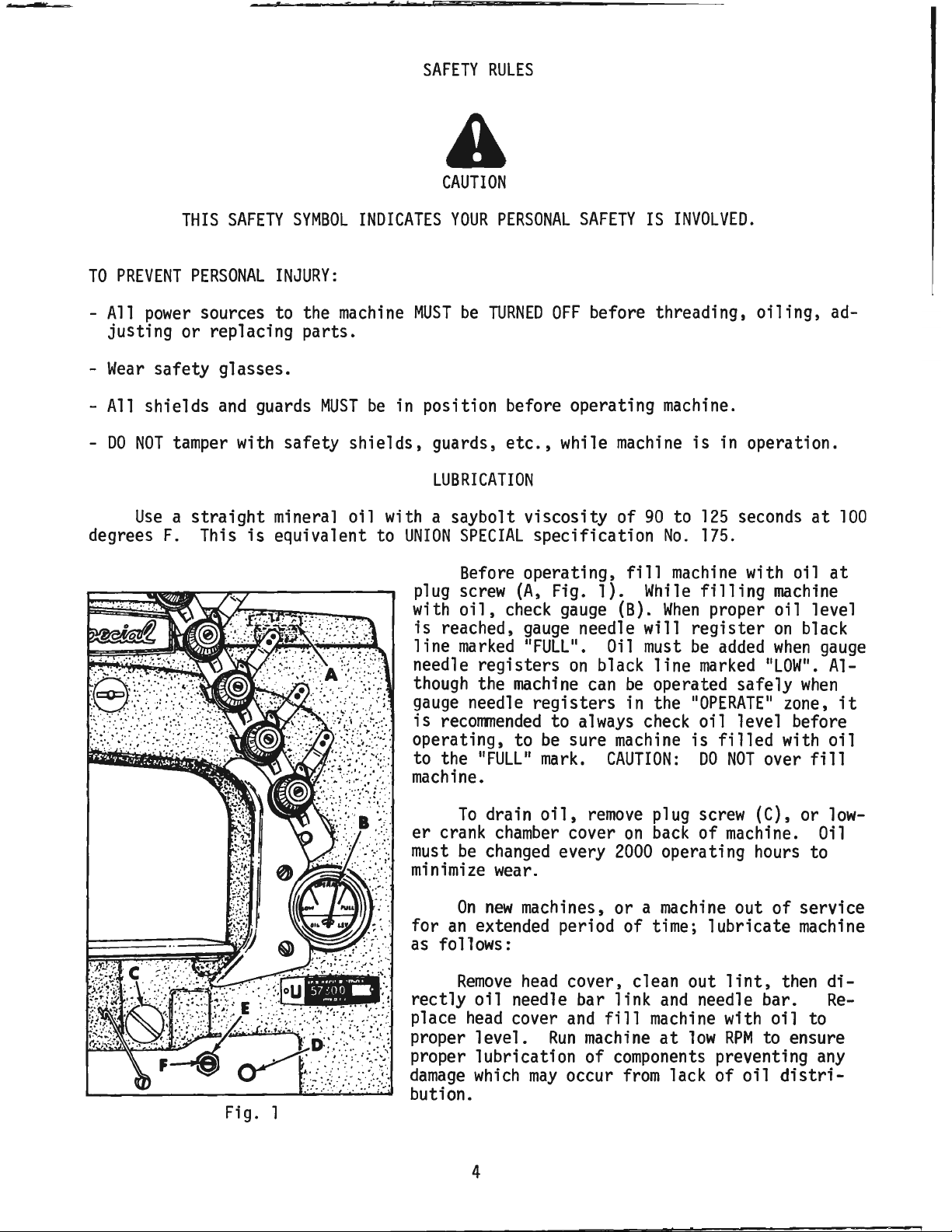
Before
screw
oil,
check
marked 11FULL
the
needle
OFF
while
specification
operating,
(A,
Fig. 1).
gauge
gauge
machine
11
11
on
registers
to
be
sure
mark.
SAFETY
before threading,
needle will
•
black
can
always
IS
machine
90
fill
While
(B).
Oil
must
be
in the
check
machine
CAUTION:
INVOLVED.
oiling,
machine.
is
in operation.
to
125
seconds
No.
175.
machine
When
register
be
line
operated safely
"OPERATE"
is
with oil
filling
proper oil level
added
marked
oil
filled
DO
machine
on
when
"LOW".
zone,
level before
with
NOT
over
ad-
at
at
black
gauge
Al-
when
oil
fill
100
it
To
Fig. l
drain
er
crank
must
minimize
for
as
rectly
place
proper level.
proper lubrication of
damage
bution.
be
changed
On
new
an
extended period of time; lubricate
follows:
Remove
oil
head
which
4
oil,
chamber
every
wear
.
machines, or a
head
needle bar link
cover
Run
may
remove
cover
cover, clean out
and
fill
machine
occur
plug
screw
on
back
2000
machine
components
from
of
operating
machine
and
needle bar.
at
low
lack of
(C), or
machine.
hours
out of service
lint,
with oil to
RPM
to ensure
preventing
oil
Oil
to
machine
then
any
distri-
low-
diRe-
Page 5
To
recalibrate
OIL
GAUGE
oil
gauge, follow instructions in sequence as
CALIBRATION
listed
:
- Place
-
Remove
machine
plug
screw
upright
(C,
on
Fig.
voir.
-
Remove
-
Fill
-
Loosen
registers on
- Tighten locknut
- Fil l
it
should
lowe
r crank
reservoir until oil
locknut (E)
the black line
(E},
machine
Thread
with oil until
machine
be set
to barely contact
as
chamber
and
then
illustrated
stroke.
Each
of
shank, point, length, groove,
on
the needle shank, denotes
and
eye. Collectively, type
given
needle
on
the label of
has
both
all
a level surface.
1)
and
tip
machine
cover
is
even
on
with
back
bottom
rotate calibrating
marked 11LOW".
replace plug
gauge
screw
needle registers
THREADING
in
Fig.
RIGHT
needl
NEEDLES
a type
needles
and
finish
largest
and
size
packaged
size
number.
and
diameter of blade,
number
forward to drain
of
machine.
of
knee
screw
2.
e thread
other
press
(F)
as required until
(C)
and
lower crank
on
If
needle thread take-up wire
ONLY,
The
type
details.
shaft
black
at
number
The
measured
represent the complete
and
sold
by
UNION
SPECIAL.
all
oil from
bushing
gauge
chamber
line marked
bottom
of
denotes the kind
size
number,
midway
between
symbol,
reser-
(D).
needle
cover.
"FULL
is
needl
e bar
stamped
which
".
used,
shank
is
The
121
GBS,
NEEDLE
121
GBS
To
n
ee
dle
pl
ete order
NOTE:
wheel
standard
Size 080/032.
recommended
Below
TYPE
Round
single groove, struck groove,
spotted, ball point,
plated.
have
needle orders promptly
or
type
and
size
number
would
Instructions
read 111000
stating
of machine, are given
right e
rotates
nd
counterclockwise, in operating direction;
of
machine.
needle for
is
the description
machines
DESCRIPTION
shank,
round
point, short
chromium
and
accurately
should
needles,
ADJUSTING
be
forwarded.
Type
121
GBS,
INSTRUCTIONS
direction or location,
relative
to operator's position
covered
and
sizes
filled,
Use
Size
such
by
this
available:
an
empty
description
080/032
as
right,
at
11
the
when
catalog
SIZES
is
Typ
AVAILABLE
065/025, 070/027,
075/029, 080/032,
090/036, 100/040.
package, a sample
on
label. A
•
left,
front or
machine.The
viewed
from
e
com-
rear
handthe
5
Page 6

Take-up
only right needle thread
at
wire must contact
bottom
of
stroke.
CAUTION: FIii oil reservoir before starting.
Machine has been drained before shipping.
THREADING
Thread
machines
machine
are threaded in a similar
to contact only the
all
Styles except
be
set
to contact
Oil
has
been
filled
before
starting
as
indicated.
RIGHT
57800
BOTH
V-8.
needle threads
drained
to operate. Refer to
AND
OILING
DIAGRAM
Three
manner.
needle thread
On
Style
from
machine
Fig. 2
FOR
CLASS
needle
machine
Needle
when
57800
when
needle bar
V-8,
needle thread take-up wire should
needle bar
before shipping
"LUBRICATION".
6
57800
MACHINES
illustrated,
but
two
thread take-up wire should
is
at
is
at
bottom
and
the reservoir
bottom
of stroke
of stroke.
must
needle
be
set
on
be
Page 7
NEEDLE
BAR
ALIGNMENT
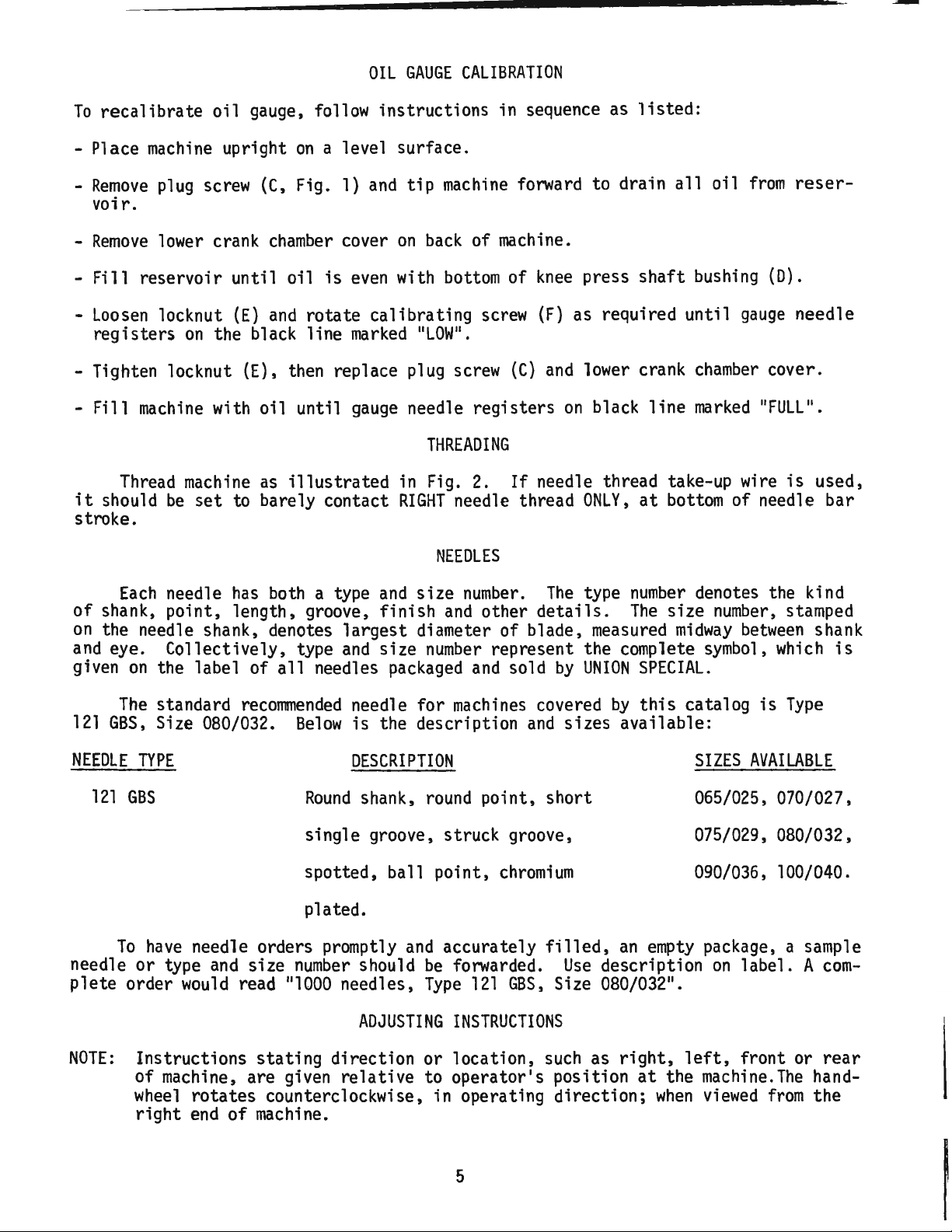
Insert a new
size required).
at
TOP
of
its
approximate
from
top
setting
of needle bar to top of needle bar
bushing (B). Adjustment
loosening
up
bar
ORARILY.
down
le
holes of throat plate as
Adjustment
(C)
turned
change
clamp
clamp
or
down,
Turn
to ensure
can
slightly,
as
required, being careful not to
the temporary height setting.Tighten..._
screw.
set
of needles (type
With
needle bar
stroke,
of l 13/32
screw
(C)
re-tighten
handwheel
that
needles center in
be
made
check
can
and
to bring needle bar
by
(A,
to ensure
inch(35.7mm)
be
moving
screw
shown
(C)
in Fig.3.
loosening
allowing needle bar to
Re-check
temporary
height
ting.
SYNCHRONIZING
Check
With
gauge
using throat plate
synchronization using
looper rocker
at
extreme
gauge
in looper hole of looper rocker.
mounting
screws. Insert
needle thread take-up wire in top of
rection until pin contacts
cator until
with the
machine
of
it
rests
marking
bed
on
"O",
for securing the take-up wire.
until pin again contacts
pointer aligns with 110"
variation of
the looper drive lever rocker
below 110
one
graduation
11
on
the scale, the shaft
edge
of
gauge
top
of needle bar
then lock indicator in position using the
edge
on
of
gauge
scale, looper
is
permissable.
shaft
must
and
Fig.
3)
an
made
by
needle
TEMP-
need-
screw
be
____________
set-
LOOPER
right
machine
AND
No.
21227
end
Assemble
shank
bed.
NEEDLE
Ras
of
travel,
gauge
of indicator into hole
Turn
plate. Adjust pointer
and
its
pointer
Turn
plate,
must
be
moved
then
and
needle
If
be
moved
to the rear.
the reading
to the front.
._
______
Fig. 3
MOTIONS
follows:
insert
pin furnished with
plate to throat plate
handwheel
on
handwheel
NOTE
reading
motions
is
in operating
on
left
end
the
right
set
end
screw
in reverse direction
on
indicator.
are synchronized. A
above
11
"0
on
If
the reading
seat
used
for
dir-
of indi-
aligns
in
front
If
scale,
is
_
If
gauge
No.
21227 R is
not available,
check
synchronization
Insert looper into the looper rocker,pushing
en
screw
Turn
handwheel
until the point of the looper
moving
side of right needle (B).
of the
the looper point
handwheel
the point of the looper again
the
left,
right
of
needle
the
the looper point are the
needle
ation of
it
all
the
way
down
and
against
flat
on
shank
of looper.
in the operating direction
(A,
to the
eye
left,
is
even
Note
with the
the height
of the needle with respect to
(See
Fig. 5).
Turn
in the reverse direction until
moving
is
eye
of
motions
.005
even
(See
with the
Fig. 5).
left
If
the height
the needle with respect to
same,
looper
are synchronized - a
inch
(.127ITITI)
is
allowable.
tight-
Fig.
4)
left
the
to
side of
and
vari-
•
7
Fig. 4
as
follows:
Page 8

SYNCHRONIZING
For Proper
the
se
SYNCHRONIZATION of
Looper
two Dimens ions w
& Needle
~
J.
-,:t,LJ.
i...._,,,==--_l·~=----
.3:•,.,,...
1)4
-~
Needl
OPERATING
Directi
~~
-1
e
In
on
3''11
ill
be the same
l
,,
Loop
FRONT of
N
ee
in
REVERSE
Dir
ec
~
er
in
dle
tion
LOOPER
AND
NEEDLE
If
the distance
of
point
is
turned in the operating
the looper
drive lever rocker
slightly
wards
NOTE:
towards the
the
The
Fig. 5
height.
MOTIONS
front
3/64 inch
is
from
shaft
acts
for
(Continued)
the
eye
of
is
greater
direction,
will
rear.
Moving
the reverse.
(l.2111Tl)
final
setting
the needle
when
the
the looper
have
to
be
the
dimension
of needle bar
to
the
handwheel
moved
shaft
shown
to-
in
Fig. 5
0
Fig. 6 .
left
At
side of
inside e
this
dge
time, there should
cone
{A).
of
looper drive lever
Adjust looper drive rocker lever
~
~!18
\tl
~ ~
gauge
If
(C)
against the
be
no
adjustment
clearance
is
left
necessary, loos
as required, then tighten s
shaft
Loosen
drive lever
Union
Special
threaded
er
shaft
usting screw (E).
required to position
screw
(D).
into
(C,
Fig. 4) in looper
A
rod
of
Screw
No.
22870 A can
the looper drive lever rock-
through the center
Tap
or
pull
shaft
for
chronization. Tighten screw
and
remove
shaft.
thrust
rod or
Loosen
screw
lock nut
adjusting screw
used
(F)
(E)
to 6 i
(7cm/kg);re-tighten lock nut
With
travel,
connecting
21227
gauge
sid
e of looper rocker
between
looper
at
extreme
check location of the
rod
bearing using
DC
as
shown
in Fig. 6. Place hole
over threaded stud, then
left
en
crew
ins ide e
clamp
(B).
scr
cone
dge
ew
of
(B)
(A)
and
as follows:
.146-40 thd.
be
of
thrust a
slightly
proper syn-
(C)
securely
to
position
and
TORQUE
n.
lbs.
(F)
securely.
right
gauge and
right
gauge
set
as
end
of
looper
No.
the
shown.
left
reposition
or
dj-
as
of
If
gauge
abl e,
ance be
check
tween
and centerline
should be 4 1/16 inch
in Fig. 6;
right end
Insert a new
required
Fig. 7
wheel
is
Loop
between
and
dimensions
8
in operating direction until looper
at
its
er ga
centerline
point
No.
21227
setting
the cente
of
loop
when
of
looper
travel.
LOOP
ER SE
needle
into
uge
right
extreme
("A"
right end
, Fig. 7) is the dist
of right needle
of
looper (C); see
on
following page.
DC
is
not
avail-
with a scale. Dist-
rline of
rocker
con
er drive lever stud
(103.2mm)
is
at its extreme
as
shown
TTINGS
of
type
and size
needle
seat.Turn
of trave
hand-
l.
anc
(B)
CHART for
e
e
Page 9
Adjustment
can
turn connecting
position
{G)
is
and
tighten nut (E), then nut
in a vertical position
be
rod
made
(F)
LOOPER
by
loosening nut
as required to
and
does
SETTINGS
(D),
(Continued)
(it
attain
(D).
NOTE:
not bind
has a left
dimension
Be
after
hand
11
(11A
).
Hold
sure
that
adjustment.
thread)
connecting
the
left
and
ball
nut (E);
rod
in
joint
MACHINE
57800
57800
direction,
to the
brush but not pick
STYLE
E-16,
W-14,
P-8,
V-8,
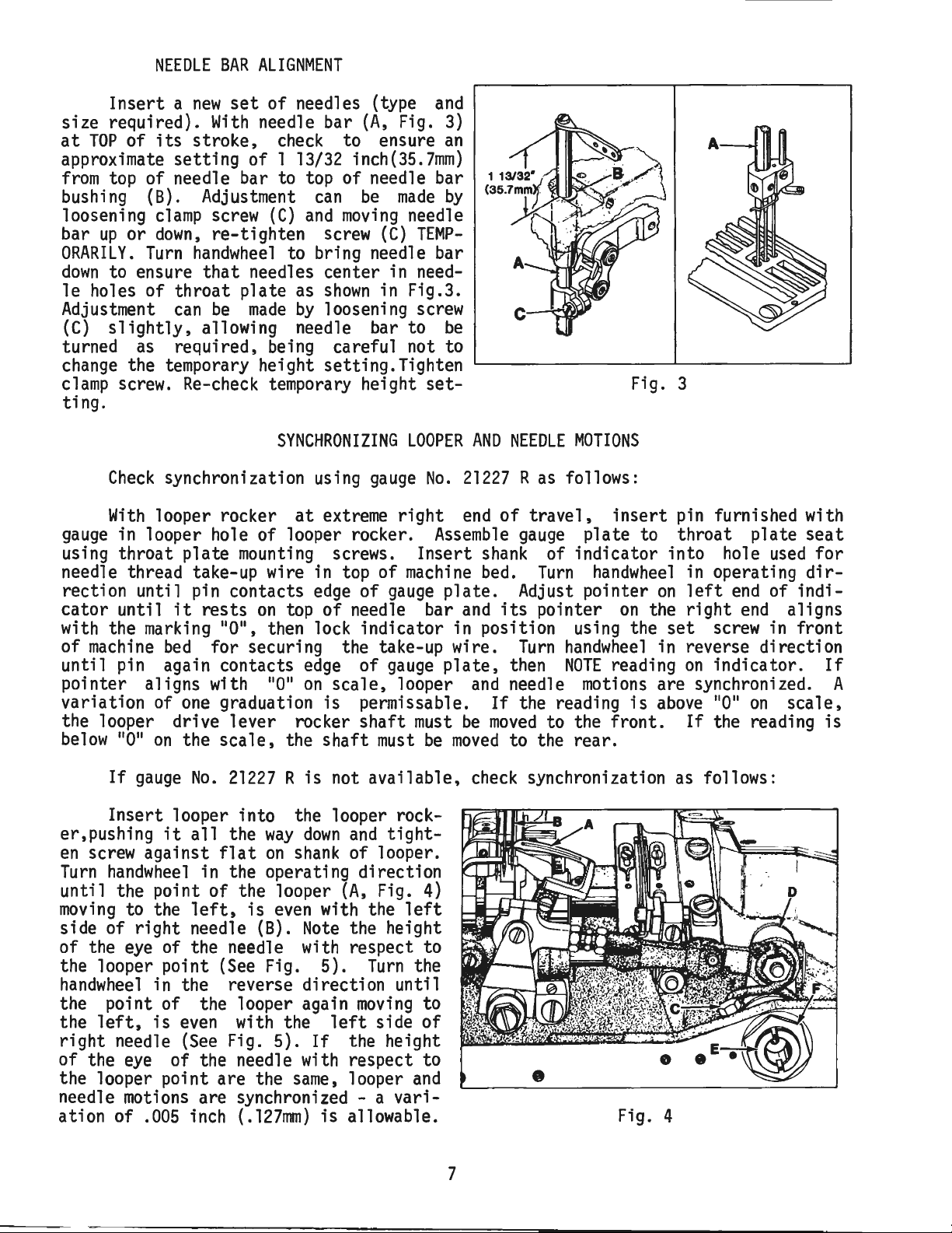
While
left
M-16,
W-16,
U-8,
U-12,
V-12
turning
as
the looper
its
point should
N-16,
X-16
handwheel
at
needle (8). Adjustment
loosenin9
screw
the
rear,
verse.
wards
ment.
has
been
screw
(J}
clockwise to
(H,
Fig. 7), turn stop
counterclockwise acts the re-
It
is
suggested to
the front while
Tighten
made
screw
and
making
(H)
recheck
looper.
NEEDLE
BAR
(A,
the
REAR
can
move
hold
after
movement
HEIGHT
DIMENSION
3/16
7/32
in
operating
Fig.
8)
be
set
of
RIGHT
be
made
looper
towards
looper to-
this
adjust-
adjustment
of
inch
inch
moves
to
by
11
11
A
FIG.
(4.8mm)
(5.6mm)
7
AVAILABLE
LOOPER
GAUGE NO.
21225-3/16
21225-7/32
Turn
until point of looper
left
eye
and
(C,
Fig.
Retighten
handwheel
side of
bottom
3)
screw
in
operating
is
flush with the
right
needle. Final
surface of looper
move
needle bar
(C)
and
check
dir
ection Fig. 8
setting
(See
Fig.
CAREFULLY
up
to ensure
plate.
MAIN
AND
Both
DIFFERENTIAL
feed
dogs
should
FEED
be
set
DOGS
to
rise
the depth of a full tooth, approximately
3/64 inch (l .
highest point of travel
slots
of
21t1n)
above
throat plate
throat plate
and
centered in
at
maximum
at
feed
travel.
Height adjustment
loosening screws
ential
dog
adjust
(D)
feed
(D).
screw
dog
Raise or
(E)
before tightening
(A,
(B)
to support
and
low
can
Fig.
(C)
er
screw
be
9)
for
as
required
main
(C).
made
for
main
by
differ-
feed
and
feed
dog
is 3/64 inch (1.
5).If
or
that
adjustment
down,
not to disturb alignment of
needles center in needle holes of
2mm)
is
between
required, loosen screw
Fig. 9
top
of needle's
same.
throat
C
9
Page 10

MAIN
AND
DIFFERENTIAL
FEED
DOGS
(Continued)
NOTE: A change
rear needle
To
center
feed
dog,
slightly
be
centered
left
as
required, retighten screws.
in
of
main
to
right,
main
guard
feed
feed
(F).
dog
loosen
throat plate
Fig.
10
dog
height will necessitate a
in
throat plate
screws
(A,
slots,
Fig. 10), reposition feed rocker
Loosen
slots
left
to
right,
Loosen
operating direction
tial
the
tial
feed
ance
feed indicator
same
feed
dog
from
screws
(G)
to
so
feed
throat
tighten
Turn
check
feed
dogs
slots.
check
front to
screws
(C)
back
allowing
retighten screws.
screw
(D),
and
(E)
amount
at
should
end
(F)
be
moved
dog
plate,
screws
handwheel
to ensure
and
of
travel.
extreme
have
of throat plate
allowing
differential
forward, rearward or turned
teeth are parallel to
across-the-line-of-feed.
(F).
in operating direction,
ample
both
ends
of the
or
setting
differential
for
(B)
main
rotate
feed
dog
handwheel
to
in
position differenso
both feeds
With
forward
1/32 inch (.8mm)clear-
end
slot.
have
differenof
travel,
Loosen
feed bar
top
of
Re-
clearance
between
of throat plate
The
differential
the selector slide
DIFFERENTIAL
feed
(E)
ratio
is
set
to the desired position.
FEED
by
loosening
accessible through the top of the cloth plate
ential feed selector
and
moving
This
of 2 to
by
hand,
of
its
it
Class of
1,
depending
making
stroke.
back
sure the
slide
(E)
decreases the
machine
on
has
a stretching
the length of
differential
toward
the front increases the
differential
stitch
feed
ratio
dog
This
(A,
thread)
stud
located under the
plate,
which
the
(moves
11
11
S
direction lengthens the stitch(moves
regulating stud
11
Fig.
locknut securely.
RATIO
on
The
the
screw
screw
left
(D,
and
side.
Fig.
selector
Moving
amount
feed. Retighten screw.
of 3/4 to l
set
at
the
clears the
CHANGING
Set the
is
accomplished
Fig.
11)
on
and
turning
in
the
is
marked
screw
clockwise shortens the
stitch
)
and
turning
main
stitch
1/2 turn
the
end
head
regulating stud
up
to a gathering
feed
main
feed
STITCH
to required length.
by
(it
of the
stitch
left
end
of the
with 11L
it
toward
11
in
a counterclockwise
the "L"). Retighten
10)
and
moving
slide
the
of
differential
are
differ-
ratio
dog.
at
Turn
the
machine
back
end
LENGTH
loosening locknut
has a left
stitch
adjusting
hand
regulating
screw
of the cloth
main
shaft (C),
and 11S
11
•
Turning
stitch
toward
the
stitch
(8)
10
Page 11

To
prevent destructive
gage
the 11U
11
shaped
CHANGING
damage
key
slot
STITCH
LENGTH
(Continued}
to the feed drive bearing, the
in
the ferrule
(E}.
Key
screw
(D}
must
en-
NOTE:
needle
Any
needle
At
extreme
guard
change
guard
REAR
(A,
in
stitch
setting.
NEEDLE
forward
Fig.
length will necessitate a corresponding
GUARD
end
of
travel,
12}
must
be
set
horizontally not to contact rear of
needle
inch
as
approach
(B}
with a
(.13mm}.
Guard
possible, yet
approximately 3/64 inch
maximum
should
have
its
clearance of
be
set
vertical face
(1.2mm}
needle point until point of looper
moving
Adjustment
(D},
to the
left,
can
reposition
be
guard
is
made
even
by
loosening
as
required
with the needle.
and
tighten screw.
NOTE:
Adjustment
of rear needle
guard
FRONT
rear
right
.005
as
low
of
(C},
screw
re-
will necessitate checking
NEEDLE
GUARD
Fig.
change
12
main
feed
in the rear
dog
height.
Front needle
left
rear
needle
time.
guard
by
needle
and
left
guard
Forward
as
required
loosening
(F}
should not
screws
NOTE: A change
ting.
The
thread tension release is
as
function
of the
foot
has
If
{A,
Fig.
end
the presser foot
of
reached
adjustment
13},
disc separator
there should
be
guard
towards
side of needle.
or rearward adjustments
and
in
stitch
its
travel
its
is
located
as
required. Retighten screw. After adjustment
no
binding
(E,
Fig.
the path of looper
make
12}
Looper
should
may
be
set
as
(C}
until point of looper passes to the
brush but not pick
contact with rear needle
can
be
made
by
loosening
retighten screws. Height or rotation of
{H},
reposition
length
THREAD
TENSION
and
is
is
as
WILL
required
NOT
require a
and
retighten screws.
change
RELEASE
set
correctly
when
raised to within 1/8 inch
entirely
released
when
highest position.
needed, loosen tension release lever
at
the
back
at
any
of the
point.
machine
and
move
low
as
possible, yet
at
the
guard
or right needle
screws
guard
in front needle
it
begins to
(3.2mm}
the presser
screw
tension
left
needle. Front
(G},
can
be
guard
push
the
at
any
reposition
acquired
set-
11
Fig.
13
Page 12

PRESSER
BAR
HEIGHT
1/16"
(1.6m~
Height
is
correct
ed
by
loosening stop
pressing foot
There
should
(1.6mm)
presser bar connection
14)
and
bed
casting
leased
throat
and
plate
of
presser bar
when
presser foot
collar
lifter
be
clearance
bottom
surface
when
lever
approximately 1/16 inch
between
foot
lifter
presser foot lying
with feed
and
of
dog
plate.
can
be
Adjustment
handwheel
of stroke.
to position needle bar
Loosen
made
screw
while holding presser foot
plate,
guide
clearance
position presser bar connection
as
required to
and
retighten screw.
attain
Set presser bar stop
14)
so
presser foot
spreader
when
raised.
does
not contact
(A,
Fig.
14)
can
be
remov-
(B)
and
de-
(B,
Fig. 13).
lower surface of
guide (C, Fig.
head
below
(D,
down
opening
lever
flat
by
turning
Fig.
on
throat
at
14)
in
is
re-
on
bottom
and
throat
and
specified
collar
(B,
Fig.
Set the arc travel of the spreader point
below,
by
loosening nut
to the desired
rocker shaft
rocker
nut
shaft
(H).
Fig.
amount
Fig.
(G).
arm
14
of arc
15
Adjustment
(J)
to positi
(E,
SPREADER
Fig.
14)
ADJUSTMENTS
(A)
and
moving
to point
the connecting link
travel.
Machine
57800
57800
57800
57800
57800
57800
57800
57800
57800
57800
57800
After
Styles
E-16
M-16
N-16
P-8
U-8
U-12
V-8
V-12
W-14
W-16
X-16
making
tightening nut (E),
arc
of
travel of link
tance
is
made by
on
the connecting link properly.
loosening nut
from
(B)
figure
15
(F)
Spreader
11/16
11
/ l 6 II ( l 7 ,
11/16
9/16
9/16
5/8
9/16
5/8
21 / 32
11
/ 1 6
11 / 16
the travel adjustment
check
the center
(H)
and
moving
to
see
(F)
is
equal
of
the spreader
the spreader
Be
sure to
as
up
or
Arc
11
(17
11
(17.5mm)
11
(14.3nm)
11
(14.3mm)
II
(
15 • 9mm)
11
(14.3mm)
11
(15.9mm)
II
( l 6 •
II
(
17 • 5mm
II ( l 7 •
that
retight
listed
down
Travel
.5mm)
5mm)
7mm)
5mm)
and
re-
the
dis-
)
en
12
Page 13

SPREADER
ADJUSTMENTS
(Continued)
With
and
spreader
travel,
(A,
Fig.
(5.6nun) to the
left
needle. Adjustment
loosening screws (B), reposition spreader
as
required being sure to
spreader holder
on
spreader holder (L) while tightening
screws
(C)
acts
er
holder
Bottom
set
21/64 inch
plate
of
travel,
the
shank
inch
by
loosening
er
as
NOTE:
needle bar
at
point
16)
(B,
as
(See
(.4
to
required
It
these adjustments to
ed
of
should extend
left
Fig.
lower
carrier.
surface
(8.3mm)
Fig. 16).
spreader
of
left
.8mm).
screws
and
may
be
dimensions.
at
extreme
thread carrying notch
of the centerline
carrier
16)
because spreader holder
thrust
of
At
must
needle
Adjustments
(D), reposition spread-
reti
necessary to coordinate
top
of
its
stroke
left
end
of
its
7/32
inch
can
be
made
push
down
(K,
Fig.
collar
spreader should
from
ghten screws.
top
extreme
be
set
by
1/64 to 1/32
attain
by
on
14)
and
for spread-
of
throat
right
to
clear
can
be
specifi-
of
be
end
made
up
Fig.
16
(
'
Stationary thread guide
proximately 3/32 inch
quired.
be
positioned with
the
guide (E).
stroke,
and
the clearance equivalent to the
Type 121
(2.mm).
as required.
ed
by
tric
rotating
the spreader should begin to
left
from
made
tric
Moveable
front
top of thread guide
Timing
as needle bar
bottom
by
against spacing washer
end
of
slot
With
lower surface
needle, approximately
Screw
of
the position of spreader drive eccen-
(A,
Fig.
handwheel
of
loosening screws (B),
needle bar
(H)
spreader travel
17)
stroke.
(2.4mm).
thread eyelet
its
eye
in stationary thread
of
will allow repositioning
on
the crankshaft.
in operating
rises
Adjustment
(E,
directly
at
thread
(E)
should
move
1/8 inch
(C)
Fig.
Attaching
(G)
should
over
bottom
eyelet
have
shank
.080
inch
is
determin-
direction,
to the
(3.8rrm)
can
advance
when
tightening screws
16)
of
(G)
of
a
While
be
or
retard
should
screws
9
be
set
to
clear
(F)
will allow repositioning as
--...;;;,,;,;o1,......
eccentric as required. Thrust eccen-
(B).
right
i;.;..,;;,.......
...,
Fig.
17
needle
__
_,
by
9
ap-
re-
NOTE:
Thread
machine
as indicated in Fig. 2.
13
Page 14

THREAD
TENSION
Pull the thread through the eyelets
tensions
at 4 oz.
thread tension
.---iiiii~
':..
-=-------:::----------
~~
E (85.05
(113.40 gr. )
at
3 oz. (85.05
i~
:#~~1t;~~~~~~~~~~~~
-----ra==='--------""------
Fig.
18
Set the needle thread
mounting
of
screw
(B).
frame
on
Styles
gr.)
on
---,
~~~
=-~,=.,~:Cf::.!~
- -
NEEDLE
THREAD
eyelet
and
set
the
left
and
57800
Styles
E,
M,
57800
Wand
N,
P,
X.
U,
the center needle should
gr.)
and
the
,
sion
at
4 oz.
(113.40
Set the spreader thread tension
ounce
sion.
(28.35
The
gr.)
adjusting nut
on
lever thread eyelet should
the tension
ounce
(14.18
type of thread
all
Styles.
The
ounces
---'
applied
the front of the
on
the spreader thread
gr.)
or
being
looper thread tension
(56.70
at
gr.)
the thread tension located
machine
gauge.
FRAME
(A,
Fig.
EYELET
18)
l inch
center needle thread
Set the
and
V.
right
gr.)
the
be
upper
below
left
needle
On
Style
set
at
3 oz.
needle thread ten-
on
all
Styles.
thread tenthe needle
be
set
so
is
more,
used.
on
(25.41l111)
all
just
depending
This
is
Styles.
above
above
applies to
set
It
the oil
the center
57800
at
1
that
1/2
on
the
at
2
is
on
N
amount
thread
J E
Fig.
19
of looper thread
in
system.
in
the system,
SPREADER
The
"U"
shaped
should
to
eyelet
eyelet
same
be
set
engage
the
(D)
by
makes
bottom
a looser cover thread, lowering
makes a tighter
LOOPER
To
properly control the looper thread,
follow instructions
THREAD
TAKE-UP
eyelet (C, Fig.
to allow the spreader thread
of
the needle lever
1/4 inch
(6.4mm).
cover thread.
THREAD
TAKE-UP
listed
looper thread take-up:
-
Loosen
cast-off
ing
screws
-
Loosen
as
extreme
across the
tighten
eyelets
screws
support plate
slots
- front to back, then tighten
(A).
screws
required,
left
cast-off
screws
(D)
(A,
Fig.
19)
(B)
(C)
and
adjust eyelets
so
when
the looper
the looper thread
support
(C). _
NOTE:
to the front to increase the
or to the rear to decrease the
18)
Raising the
for adjusting the
and
center
in
its
adjust-
(D)
is
at
its
is
taut
plate,
then
Re-position
amount
of
14
Page 15
LOOPER
-
To
adjust looper thread take-up (E), loosen screws (F),
through
til
of looper.
thread take-up.
screws
slot
in
cast-off
needles are descending
At
this
time
If
required,
{F)
be
sure take-up
support
the looper thread should cast
THREAD
and
the
make
is
centered
TAKE-UP
plate.
tip
Turn
of
(Continued)
handwheel
left
needle
the necessary adjustments . Prior to tightening
left
to right in
slot.
-
Loosen
then tighten
screw
(G)
and
screw
center
(G).
cast-off
wire
(H)
in
slot
in
operating direction
is
visible
off
the
cast-off
which
are accessible
on
the underside
high
lobe of looper
support plate
of looper thread take-up,
un-
- Retaining finger
is
set
properly
(J)
when
controls the
it
prevents the looper thread
amount
the looper blade, while looper travels
finger
parallel with the top surface of
centered
screw
take-up
(J),
(L)
slot,
loosen
in
retaining finger adjusting
and
screw
(K)
and
center the retaining finger
then tighten
screw
adjust retaining finger
cast-off
(L).
SPREADER
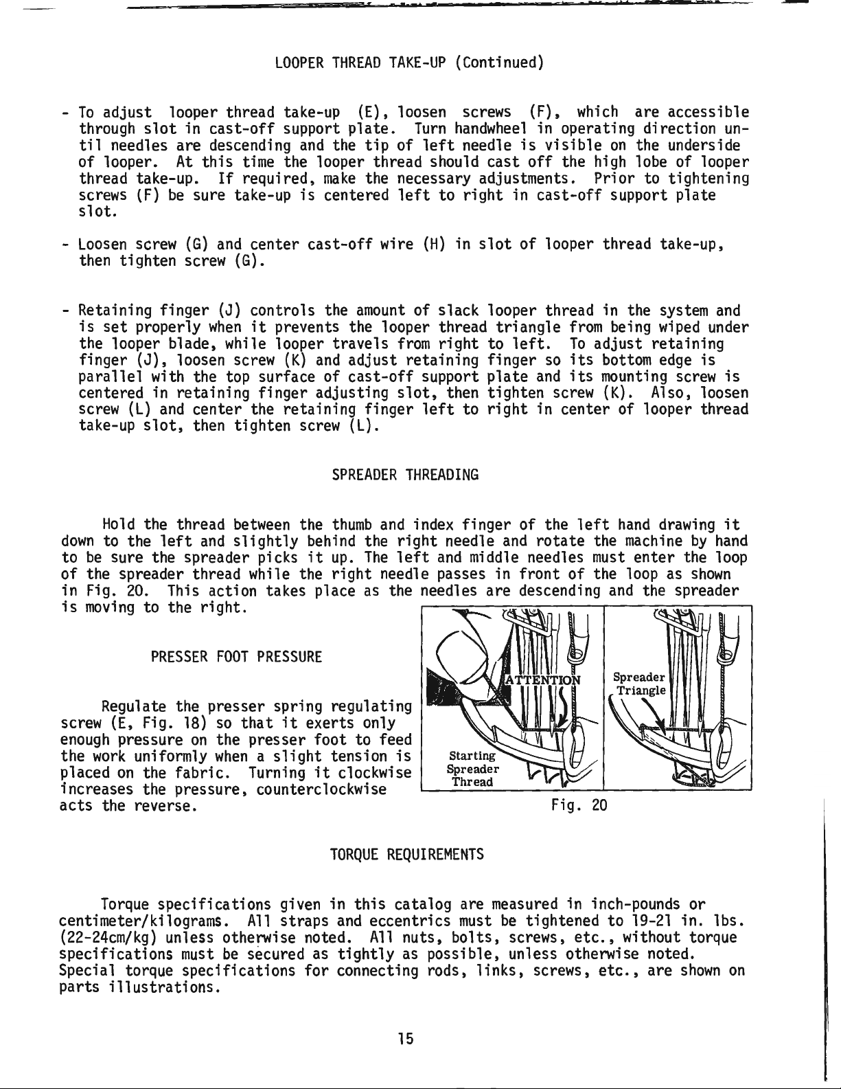
Hold
the thread
down
to
to the
be
sure the spreader picks
left
of the spreader thread while the
in Fig.
is
moving
20.
This action takes place
to the right.
PRESSER
and
FOOT
between
slightly
PRESSURE
the
behind
it
thumb
the right needle
up.
The
right
as
Regulate the presser spring regulating
screw
enough
the
placed
(E,
pressure
work
on
Fig.
18)
on
uniformly
the fabric.
so
that
it
exerts only
the presser foot to feed
when a slight
Turning
tension
it
clockwise
increases the pressure, counterclockwise
acts the reverse.
of slack looper thread in the
from
support
slot,
left
triangle
right
to
left.
plate
then tighten
to
right
from
To
adjust retaining
so
its
bottom
and
its
mounting
screw
(K).
in center of looper thread
THREADING
and
index finger of the
and
left
and
middle
needles
left
rotate
the
must
needle passes in front of the
the needles are descending
and
is
Fig.
20
system
being
wiped
edge
Also, loosen
hand
drawing
machine
enter the
loop
as
the spreader
under
is
screw
by
shown
and
is
it
hand
loop
TORQUE
Torque
centimeter/kilograms.
(22-24cm/kg)
specifications
specifications given in
All
straps
and
unless otherwise noted.
must
be
secured
as
tightly
Special torque specifications for connecting rods,
parts
illustrations.
REQUIREMENTS
this
catalog are
eccentrics
All
nuts,
as
possible, unless otherwise noted.
15
measured
must
bolts,
links,
in inch-pounds or
be
tightened to
screws,
screws,
etc.,
etc.,
19-21
in.
lbs.
without torque
are
shown
on
Page 16

SPECIAL
INSTRUCTIONS
Fig.
21
When
ing
related
sequence
l.
Install 110
adjusting needle lever or replac-
as
needle lever stud
NEEDLE
parts,
listed:
11
rings
LEVER
follow instructions in
(A,
Fig.
(B)
and
(C).
2.
With
needle lever
positioned properly;
through hole in needle lever until
shoulder contacts the needle lever
the
word 11UP
position.
exists
stud
top
3.
(B)
of
Install
machine
pression
push
ring
machine
11
While
in the needle bar
with the front
temper
cups
and
bed.
(D)
in
machine
insert
on
stud
making
is
in the upright
sure
link,
set
bed.
load ring
(F)
onto stud (B), then
cups
through
(E)
21)
onto
thrust
stud
no
secure
screw
and
opening
collar
and
(B)
its
and
binding
in
com-
in
Fig.
Fig.
22
.045" ( 1.14mm)
23
ALIGNING
MAINSHAFT
4.
Install
being careful not to
Compress
ing
thrust
screw
collar
components
(G)
until
(C)
onto stud
damage 110
together
washer
11
by
(H)
against stud (B). Secure stud
position using the rear
bed.
of
5.
To
check
pression,
and
loosen rear
Thrust
-
.007
temper
remove
collar
(C)
inch (.08 -
load ring for proper
screw
set
should spring out
set
(G)
screw
.18mm).
screw
from
in top of
Compress
ring in reverse order, then tighten rear
set
screw.
6.
With
position,
its
stud.
their
of oil will
indented 11UP
install
hook
sets
When
hook
proper positions,the proper
be
lubricating needle lever
TO
CRANKSHAFT
11
on
stud (B)in upright
in
bearing
oil
and
oiler
supply hole
stud are secured in
channeled to stud for
(D).
(B)
ring.
tighen-
bottoms
(B)
in
in top
com-
stud
bed.
.003
load
(J)
so
(K)
of
amount
(B)
As
viewed
couplings
must
align with the
positioned
head
and
the
looking
must
align with the spots in the looper drive crank
laterally
bed
casting
down
flats
with
from
on
crankshaft
.045
as
shown
rear of
inch (1.
in
Fig.
machin
(D)
14nm)
23.
16
e, spot
and
mainshaft (E). Mainshaft
clearance
screws
between
(A,
Fig.
22)
in the
(B)
and
set
screws
must
the right side of
(C)
be
its
Page 17

ALIGNING
MAINSHAFT
TO
CRANKSHAFT
(Continued)
Looper
(.8mm)
are
made,
quence
Tighten spot screws
screws
21
in.
screws
screws
cm/kg), then, torque screws
19 -21
The
in the
with
bed
without touching.
holes
screws
oil
its
casting,
and
drive crank
clearance
it
for
best performance.
(C)
temporarily, to the crankshaft
lbs.
(A)
and
(F)
to
in.
lbs.
oil
between
is
very important
(22 -24
set
screws (C). Re-torque
19 -21
(22 -24
drip
plate
reservoir
tip
in the recessed cut out in the
as
far
It
can
be
adjusted
(B) in top of the
(B,
cm/kg).
in.
(A,
should
to
the
has
Fig.
it
and
mainshaft
that
(A)
temporarily, to the looper drive crank. Tighten s
Loosen
lbs.
(22 -24
(A
and
cm/kg).
Fig. 24)1ocated
be
positioned
left
as possible
elongated
by
loosening (2)
oil
reservoir
22)
must
the couplings
spot
C)
to
mounting
back
cover to position as required, retighten
screws.
be
positioned
(E)
as
and
mainshaft.
shown
are
laterally
in Fig.22.
with 1/32 inch
Once
these
settings
tightened in the following
et
Torque
Fig.
screws
24
B
(F)
G
to
19
se-
-
•
0
17
Page 18

25
21
CAUTION!
Fi
ll
oil
before
starti
Machine
drained
shipping.
reservoir
before
has
ng.
been
.
36
18
Page 19

R
ef.
~
l
2
3
4
5
6
7
8
9
10
11
12
13
14
15
16
17
18
19
20
21
22
23
24
24A
25
26
27
28
29
30
31
32
33
34
35
36
37
38
39
40
41
42
43
44
45
46
47
48
49
50
51
52
53
54
55
56
57
58
59
60
61
62
63
64
65
66
67
68
68A
69
70
Part
No.
56382
56382
56382
56382
22829
56382
22848
22524
56382
22548
56382
56382
56382
22733
22541
56382
56382
90
56382
22539
21375
22829
98
98
158
52858
56391
52904
52804
87
22768
52904
50-216
22516
73
22569
69
57757
52958
73
52904
52958
22848
20
51858
22889
22585
95
57844
57858
57844
57892
80665
57892
57892
22542
57844
57944
57944
605
57882
22733
22569
22569
57882
22564
57831
22513
35731
22539
57770
56470
660-617
22894
Y
AB
K
J
AA
L
D
E
M
E
C
B
C
AC
S
AV
A
A
B
Block, clamping,
Plate, oil
Gasket
Cover,
Screw
Cover,
Screw
Screw----------------------------------------------------
Gasket
Screw----------------------------------------------------------
Cover,
Gasket
Gasket--------------------------------------------------------Plug
Screw,
Screw
Cover,
Gasket
Screw-------------------------------------------------------------
Oiler
Plug
Screw------------------------------------------------------
Guard,
Screw
Screw,
Screw,
Eyelet, looper thread,
Eyelet, looper thread, Style
B
E
U
E
A
C
H
B
D
A
G
B
A
C
B
Guard,
Finger,
Support,
Screw
Screw-----------------------------------------------------------------------------------
Support, retaining
Blk.
Pin,
Screw-----------------------------------------------------------------------------------
Screw
Screw-----------------------------------------------------------------------------------
Washer
Support,
Eyelet, take-up, looper
Screw
Wire,
Eyelet, looper
Screw
Washer----------------------------------------------------------------------------------
Eyelet, frame, needle
Plug
Screw,
Screw
Plug
Screw-------------------------------------------------------------------------Plate, mounting, spreader thread
Eyelet,
Guide,
A
F
C-5
B
A
A
B
A
C
C
C
B
B
A
G
Post, spreader
Disc, spreader
Spring, tension,
Nut,
spreader tension
Screw
Guide,
Eyelet,
Guide,
Screw
Cover,
Plug
Screw,
Screw,
Gasket---------------------------------------------------------------------------------Screw
Plate, guide, presser bar connection
Screw
Plate, guide, presser bar connection
Plug
Screw----------------------------------------------------------------Wire,
Wire,
Gasket, needle lever
E
Screw
MAIN
FRAME,
CAST-OFF
PLATE
AND
MISCELLANEOUS
COVERS
Description
oil
drip
drip--------------------------------
plate-------------------
----------------------------------------reservoir, looper drive
-----------------------------------------------------back,
oil
reservoir-----------------------------------------
shaft--------------------------
------------------------------------------
----------------------------------------------------crank
chamber,
lower-------------------------------------------------------------
--------------------------------------------------------
oil
filler----------------
-------------------------------------------------crank
chamber,
upper--------------------------------
-
-------------------------------------------------
----------------------------------------------------------------------------------
and
Baffle Plate
Assembly,
needle lever
belt--------------------------------------------
------------------------------------------
Styles
Styles
57800
57800
E,
M,
Na~ X -------------------------------------------------------
P,
U, V and\W
all
Styles except
--------------------~---------------------------------57800 P ----------------------------------------
--
----------
--
---------------------------------------
-
----------------
-.
---------------------------------------
--
---
-----------------------
------------------------
--
------------------------
--
---------------------------
-
--------------------
-
------------------------------
-
----------------------------
-
------------------------
---
-----------------------
-------------------------
------
-----
-
----------------------------
--------------------
--
--------------------
bearing-----------------------------------
-
---
------------
-
---------------
-----------------------
------------------
---
----------------------
57800 P ----------------------------------------------------
looper thread, Styles
retaining-----------------------------------------------------------------------
57800
E,
M, N and X -------------------------------------
retainer-----------------------------------------------------------------------
----------------------------------------------------------------------------------finger---------------------------------------------------------------
dowel
--------------------------------
--------------------------------
---------------------------------------------------------------------------------cast-off
plate-----------------------------------------------------------------
-
--------------------------------------------------
-
----------------------------------------
thread----------------------------------------------------------
----------------------------------------------------------------------------------cast-off--------------------------------------------------------------------------
thread-------------------------------------------------------------------
----------------------------------------------------------------------------------thread------------------------------------------------------------
adaptor---------------------------------------------------------------------
-----------------------------------------------------------------------------------
eyelet-------------------------------------------------
pull-off,
spreader
spreader
thread-------------------------------------------------------
thread-----------------------------------------------------------------tension-----------------------------------------------------------------tension------------------------------------------------------------------
spreader---------------------------------------------
-
-----------------
post--------------------------------------------------------------
----------------------------------------------------------------------------------thread---------------------------------------------------------------------------
thread--------------------------------------------------------------------------
spreader
----------------------------------------------------------------------------------head-----------------------------------------------------------------------------
and
needle
thread-------------------------------------------------------
Screw-------------------------------------------------------------------------
all
Styles except
Style
57800 E --------------------------------------------------------------------
-----------------------------------------------------------------------------------
-----------------------------------------------------------------------------------
take-up, needle thread,
take-up, needle thread, for
57800 E --------------------------------------------------------
{rear)----~----------------------------------------
(front)--------------------------------------------
-
all
Styles
No.
and
8 gauge, Style
gauges
except
57800
V-8
--------------------
57800 V ----------------------------
------------
eyelet-------------------------------------------------------------
-----------------------------------------------------------------------------------
Amt.
~
l
l
1
l
2
l
9
2
l
4
l
l
l
l
4
l
l
2
l
l
l
2
3
2
l
l
l
-
--
l
l
l
1
l
l
l
l
2
2
l
2
2
l
l
l
l
l
l
l
l
-
---
l
l
l
l
2
1
1
2
1
l
l
2
l
l
3
l
l
2
1
2
l
l
l
1
l
2
19
Page 20

20
Page 21

MAIN
FRAME,
BUSHINGS,
OIL
GAUGE
AND
MISCELLANEOUS
OILING
PARTS
Ref.
No.
l
2
3
4
5
6
7
8
9
10
11
12
13
14
15
16
17
18
19
20
21
22
23
24
25
26
27
28
29
30
31
32
33
34
35
36
37
38
39
40
41
42
43
44
45
Part
No.
59493
666-214
57849
52883
21657
56390
56390
660-665
22569
57890
56390
63494
63494
63494
660-455
56394
22793
56394
660-221
61256
11635
56394
22772
57894
56342
22539
52942
52942
50-895
56393
666-259
56390
57836
57842
56190
56393
35897
56390
57893
666-214
51257
56354
57846
56393
51154
A
R
X
H
J
B
B
E
K
F
G
B
C
G
B
A
B
D
R
AC
AB
P
B
B
Q
BV
G
AA
C
W
E
Blk.
Description
Oil
Pump
Assembly,
Felt,
intake-----------------------------------Bushing, spreader rocker
Bushing, presser foot
Bushing, release
Washer,
Ring,
thrust---------------------------------------
pilot-------------------
Bearing, needle
base------------------------------
shaft-----------------------
lifter
lever-------------------
lever-------------------------------
--
---------------------
thrust------------------------------Screw-----------------------------------------------Housing, crankshaft
Gasket, bushing
Oil
Gauge
Assembly-----------------------------------
bushing--------------------------
housing------------------------------
Nut---------------------------------------------
Washer,
11011
Connecting
Screw------------------------------------------------
Lever
Ring,
Assembly,
oil
Washer-----------------------------------------------
spring----------------------------------
Ring----------------------------------------
Rod,
oil
gauge----------------------------
oil
gauge
float----------------------
retaining----------------------------------
Nut--------------------------------------------------
Shaft,
Screw------------------------------------------------
Deflector,
oil
gauge
oil
adjusting---------------------------
---------------------------------------
Nut--------------------------------------------------
Screw,
Screw,
Bushing, looper drive lever
Bushing, looper rocker
Felt,
plug---------------------------------thrust
synchronizing
adjusting---------------shaft
(front)------------
shaft-------------------------
base
(front)-----------------------------------
-
-------
Felt-------------------------------------------------
Bushing, mainshaft
Bushing, feed rocker
Bushing, looper drive lever
Bushing, mainshaft,
Felt,
Filter,
base
oil
(rear)------------------------------------
intake----------------------------------Bushing, mainshaft
Oil
Pump
Assembly,
Felt,
intake-----------------------------------Bushing, presser bar
Bushing, needle bar
Bushing, spreader holder
Felt,
oil
attraction---------------------------------
Bushing, needle bar
(left)----------------------------
shaft---------------------------
shaft
(rear)-------------
middle---------------------------
(right)---------------------------
head------------------------------
(lower)-------------------------
(lower)--------------------------
carrier------------
-------
(upper)--------------------------
--
Amt.
~
1
1
2
1
1
4
2
2
3
1
1
1
1
1
1
1
1
1
1
2
l
l
2
1
1
l
1
1
2
l
1
1
2
l
1
1
l
l
l
1
1
l
l
1
1
21
Page 22

:,
:~
1
_____
IN,.
,
I
~
41
40
22
Page 23

CRANKSHAFT,
NEEDLE
LEVER,
NEEDLE
BAR
AND
LOOPER
DRIVING
PARTS
Ref.
~
2
3
4
5
6
7
8
9
10
11
12
13
14
15
16
17
18
19
20
21
22
23
24
25
26
27
28
29
30
31
32
33
34
35
36
37
38
39
40
41
42
43
44
45
46
47
48
49
50
51
52
53
54
55
56
57
58
59
60
61
62
63
64
65
66
67
Part
-1i2.:..
52817
E-8
52717
E-12
52817-14
52817-16
27-435
56958
A
22768
22586
R
51250
F
51250
D
660-625
56350
E
56350
F
660-614
29348
AF
56315
A
56350
G
77
56354
D
51254
K
22562
A
22564
660-215
52336
A
W0-3
56350
D
22768
56958
29066
R
22559
G
51216
N
51216
P
56316
61321
L
22574
57821
56321
N
22894
AB
660-202
29476
NZ
51216
M
56316
C
12934
A
22894
C
22894
D
56343
F
22653
L-8
29105
AM
22559
A
56343
E
56343
C
22587
K
57818-8
89
88
B
22738
F
28
B
41076
D
57842
52942
AA
660-202
CL-21
52942
AC
56342
E
56390
H
660-665
56390
J
Blk.
Description
Needle
Needle
Needle
Needle
Lockwasher,
Bar,
Bar,
Bar,
Bar,
marked
marked
marked
marked
needle bar
Eyelet, needle bar
11
"BG-8
, for
No.
"EJ-12", for
"BD-14",
"BD-16
11
, for
for
8 gauge, Styles
No.
12
14
16
gauge,
gauge,
gauge,
No.
No.
57800
P,
E,
U,
M,
Styles
Style
Styles
57800 U and V -----------
57800 W ------------------
57800
and V ---------
N,
Wand X --
eyelet------------------------------------------------
thread----------------------------------------------------
Screw------------------------------------------------------------------------
Screw------------------------------------------------------------------------
Gasket----------------------------------------------------------------------Washer-----------------------------------------------------------------------
Ring,
oil seal
Collar,
Cup,
Load
Lever
thrust,
compression-------------------------------------------------------------
Ring,
Assembly,
Lever,
--------------------------------------------------------------needle
lever-------------------------------------------------
temper------------------------------------------------------------
needle-------------------------------------------------------
needle-----------------------------------------------------------
Bushing------------------------------------------------------------
Screw-------------------------------------------------------------------
Link, needle
Connection, needle
bar--------------------------------------------------------
bar--------------------------------------------------
Screw-------------------------------------------------------------
Screw--------------------------------
Ring,
retaining---------------------------
link-----------------------------------
Pin,
Yarn,
Stud, needle
columbia
lever-----------------
(6
strands)----------------------------
Screw------------------------------------------------
Eyelet, thread, needle
Ball
Joint
Assembly,
lever-------------------------------------------------
needle lever connecting
---------
--------------------------
·
---------
-
---------------------------
---
-----------------
--
---
-------------------------------
------------------------
{upper)-------------------------
----------- -
Screw-------------------------------------------------------------------
Washer--------------------------------------------------------
---
-----------Nut-------------------------------------------------------------------------Connecting
Plate,
Screw-------------------------------------
Handwheel
Pulley----------------------------------
"O"
Ring--------------------------------
Crankshaft
Guide,
Rod,
needle
lever-------------------------------------------------
retaining-------------------------------------------------------------
--
---------------------------------
--------------------------------------------------------------------
Screw------------------------------
----
---------------------------------
---
----------------------------------
-------------------------------------
Assembly,
Bearing,
connecting
needle---------------------------------------------------------
.910
inch
(23.11mm)
throw-------------------------------
rod-------------------------------------------------------Nut-------------------------------------------------------------------------Oil
Pump
Oil
Pump
Screw,
Screw,
Assembly,
set------------------------------------------------------------------spot------------------------------------------------------------------
Coupling, looper drive
Assembly,
head
(See
Ref.
No.
base
{See
Ref.
39 -Page
No.
1 -
Page
21)
--------------------------
21)
--------------------------
lever-------------------------------------------------
Screw-------------------------------------------------------------------
Lever
Crank
Capscrew,
Splasher, oil
Fork, guide, ball
Capscrew,
Holder,
needle--------------------------------------------------------------Screw,
Screw,
Assembly,
bearing
bearing
spot------------------------------------------------------------set--------------------------------------------------------------
looper
driving-----------------------------------------
(lower)-----------------------------------------------
----------------------------------------------------------joint-------------------------------------------------
(upper)-----------------------------------------------
Screw-------------------------------------------------------------------
Screw,
Eyelet, spreader
Guide,
Shaft, rocker, looper drive
Ring,
Wick,
Screw,
Lever, looper drive,
Washer,
Bearing,
Ring,
for center needle, Styles
57800
E,
M,
N,
Wand X ----------------------
thread------------------------------------------------------
needle
thread---------------------------------------------------------
lever--------------------------------------------
oil
seal
oil
thrust synchronizing
---------------------------------------------------------------
-------------------------------------------------------------------marked
adjusting---------------------------------------"D"
----------------------------------------------
thrust---------------------------------------------------------------
thrust,
needle------------------------------------------------------
pilot------------------------------------------------------------------
Amt.
~
1
1
1
1
1
1
1
1
1
1
2
1
2
1
1
1
1
1
1
1
- 1
1
4
2
---1
1
1
1
2
1
1
2
1
3
1
1
2
1
1
28
1
1
1
1
2
2
2
2
1
2
1
1
2
1
1
2
2
1
1
1
1
1
1
1
1
4
2
2
23
Page 24

10
Torque
to
19-21 i
n. lbs
(22 -24cm . kg. )
.
34
35
-==-=-
27
.Mt-'-1
24
Page 25

SPREADER
AND
SPREADER
DRIVING
MECHANISM
Ref.
No.
l
2
3
4
5
6
7
8
9
10
11
12
13
14
15
16
17
18
19
20
21
22
23
24
25
26
27
28
29
30
31
32
33
34
35
36
37
38
39
40
41
42
Part
No.
57845
57846
22547
77
57847
57848
97
57835
12934
61434
12538
57849
55235
6042
55235
57849
52849
57847
95
56342
660-202
57849
55235
6042
55235
22559
52952
52952
55235
6042
55235
18
HA20
57852
52916
29126
95
52951
660-246
52951
52947
22587
A
A
D
A
A
C
A
M
A
G
A
E
A
D
C
B
D
E
A
D
G
-B
C
E
A
D
A
A
CR
B
C
A
H
Description
Spreader,
Holder,
spreader------------------------------------------
marked 11J
11
--------------------------------------
Screw------------------------------------------------
Screw-----------------------------------------------Carrier,
Connecting
spreader
Rod
Assembly,
holder----------------------------------
carrier--------------------------
Screw------------------------------------------------
Washer,
ball
-----------------------------------------
Nut-------------------------------------------------------
Washer----------------------------------------------------
Nut-------------------------------------------------------
Arm,
spreader rock
shaft----------------------------------
Nut--------------------------------------------------
Washer-----------------------------------------------
Stud,
Washer,
Shaft, spreader
Collar, spreader
locking----------------------------------------
thrust--------------------------------------------
rock--------------------------------------
rock
shaft
thrust------------------------
Screw------------------------------------------------
Collar, oil seal
Ring,
oil
seal
Collar, spreader rocker
------------------------------------------
-------------------------------------------shaft-----------------------------
Nut--------------------------------------------------
Washer----------------------------------------------Stud,
locking---------------------------------------Screw----------------------------------------------------Ball
Lever, spreader rock
Joint,
spreader connecting rod,
shaft-----------
upper----------------
---
------------------
Nut--------------------------------------------------
Washer--------------------------------------
Stud,
locking-------------------
Nut------------------------
---
----------------------------
-
--------------------
Washer---------------------------------------------------Spacer---------------------------------------------------Connecting
Eccentric
Rod,
spreader
Assembly,
drive----------------------------
spreader
drive--------------Screw-----------------------------------------------Washer,
Ring,
Washer,
spacing-------------------------------------------
retaining------------------------------------
retaining--------------------------------------
Counterweight---------------------------------------------
Screw---------------------------------------
-
-
--------
-
--------
-------------
Amt.
~
l
l
2
2
l
l
4
l
l
l
l
l
l
l
l
2
l
l
2
l
l
l
l
l
l
2
l
l
l
l
l
l
l
l
2
l
2
l
l
l
l
2
25
Page 26

26
Page 27

LOOPER
ROCKER
AND
CONNECTING
ROD
PARTS
Ref.
No.
l
2
3
4
5
b
7
8
9
10
11
12
13
14
15
16
17
Part
No.
52825
22563
33174
51244
57725
57846
57744
98
719
51236
56344
C067
57744
W0-3
55244
51244
51216
18 18
19
20
21
22
23
24
25
26
27
28
29
30
31
32
33
34
35
36
37
38
39
40
41
42
43
44
45
46
47
48
49
20
18
56341
660-310
56341
56341
56341
50-458
18
57840
269
87
56393
29192
22829
258
15465
88
57713
51745
96
22874
18
73
57841
22729
52708
56342
51242
22882
52942
D
B
L
B
B
A
A
B
E
G
N
N
M
E
F
G
U
J
Z
F
C
B
E
M
C
R
Blk.
Description
Holder, needle guard,
front-------------------------Screw------------------------------------------Screw-------------------------------------------
Washer,
Guard,
Nut,
Frame,
Pin, looper avoid
Arm,
Plug,
Shaft, looper
Yarn,
Stud, looper rocker
Clamp,
thrust---------------------------------------
needle,
looper rocker
looper
Screw,
Screw,
front---------------------------------
cone
stud-------------------------
rocker--------------------------------set-------------------------------------stop-------------------------------------
link-------------------------------
looper rocker
shaft-----------------------------
cork-------------------------------------------
rocker---------------------------------
columbia
looper rocker
(4
strands, 8 inches,
shaft
collar---------------------
shaft---------------------------
203.2mm
long)
---
Washer-----------------------------------------------
Nut--------------------------------------------------
Washer-----------------------------------------------
Nut--------------------------------------------------
Connec~ing
Ring,
Pin,
Ferrule----------------------------------------Spring-----------------------------------------Pin,
Nut,
right
Connecting
Nut,
left
Screw-----------------------------------------------Oiler, looper connecting
Looper
Screw------------------------------------------Nut,
Cone,
Rocker, looper,
Stud, looper rocker
Screw-----------------------------------------------Screw,
Rod
~o~nted
reta1n1ng
Section, looper
(right)-------
---------------------------------
hinge--------------------------------------
spring-------------------------------------
hand
thread-------------------------------
Rod,
looper-------------------------------
hand
Rocker
thread--------------------------------
rod
ball
joint
(left)-------
Assembly-------------------------------
lock---------------------------------------
looper
rocker-----------------------------
Screw--------------------------------------
marked
"W"
----------------------
cone------------------------
lock, looper rocker
frame---------------------
Nut--------------------------------------------------
Screw-----------------------------------------------Connecting
Screw------------------------------------------Looper----------------------------------------------Lever, looper drive,
Washer------------------------------------------
Screw-------------------------------------------
Stud, looper
Rod
Ball
Joint,
marked
looper
"D"
(left)-------------
----------------------
lever-----------------------------------
Amt.
~
l
2
2
2
l
l
l
l
l
l
l
l
l
l
l
l
l
l
l
l
l
2
l
l
l
l
l
l
l
1
1
l
l
l
l
2
l
l
l
l
l
1
l
2
l
1
l
l
l
27
Page 28

Torque
19-2li
n.
(22-24cm.
to
lbs.
kg.
Torqu
e to
5
5in. lb
(63c m .
s .
kg. )
28
RIGHT SIDE OF MAIN SHA
HE
AD
TO
BE S
ET
F
ROM BE
D CASTING
• 045 INCH
FT
Page 29

MAINSHAFT,
TAKE-UP
AND
FEED
DRIVING
PARTS
Ref.
Part
No. No.
l
2
3
4
5
6
7
8
9
10
11
12
13
14
15
16
17
18
19
20
21
22
23
24
25
26
27
28
29
30
31
29476
55235
6042
55235
22768
56336
56336
51054
666-149
269
21657
22525
56322
22798
56336
22543
660-269
56336
22801
57822
56322
22891
52923
22580
29476
77
22894
39543
29476
77
22894
ND
E
A
D
B
B
C
E
A
C
C
A
B
D
A
B
B
D
D
NM-062
AA
N
NM-072
AA
Description
Feed
Rocker
Arm
and
Feed
Crank
Link
Sub-Assembly----------
Nut--------------------------------------------------
Washer-----------------------------------------------
Stud,
Screw-----------------------------------------------Link
Pin, feed crank link -
Nut,
left
Washer----------------------------------------------------
Screw-----------------------------------------------------
Plate,
Screw--------------------------------
Stud, feed crank,
Screw,
Ring,
quad------------------------------------------------
Insert,
Screw----------------------------------------------------Mainshaft
Gasket-----------------------------------------------
Screw,
Take-up, looper
Screw------------------------------------------------
Eccentric
throw----------------------------------------------------
Screw------------------------------------------------
Screw-----------------------------------------------Washer,
Eccentric
Screw------------------------------------------------
Screw------------------------------------------------
locking---------------------------
Assembly,
Ferrule, feed crank
feed
crank----------------------------
link------------------------
--------------------------------
Wick,
hand
mainshaft
stitch
feed crank
--------
oil
----------------
thread-------------------------------------
head-------------------------------------
marked
"A"------------------------------
regulating----------------------------------
stud-----------------------------------
---
oil
flow
----regulating---------------------------
---
------------------------------
thread------------------------------------
Assembly,
thru st -
Assembly,
looper avoid, .062 inch (1.58
------------------------------------------feed
lift,
.072
-
------------
--
---------------------
-
--------------------
mm)
inch (1.83
mm)
throw
--
Amt.
~
l
l
l
l
l
l
l
l
l
l
l
4
l
l
l
l
l
l
l
l
l
l
l
2
l
l
l
2
l
l
l
29
Page 30

30
Page 31

MAIN
AND
DIFFERENTIAL
FEED
MECHANISMS
Ref.
No.
l
2
3
4
5
6
7
8
9
10
11
12
13
14
15
16
17
18
19
20
21
22
23
24
25
26
27
27A
28
29
30
30A
31
32
33
34
34A
35
36
37
38
39
40
41
42
43
44
45
46
47
48
49
50
51
52
53
54
55
Part
No.
57835
57834
22651
61341
57836
22811
57836
57834
22597
660-438
41391
56335
98
57834
22651
57834
57834
22637
8372
35569
7947
57834
22593
22593
91
52853
52853
52953
22653
22653
51235
52825
52825
57825
52925
22635
57837
57853
57853
CL21
57834
CL21
90
51236
57835
605
57837
22743
57836
57835
57835
57835
22871
57835
22874
57837
57835
69
9937
G
N
AB-3
J
S
B
M
D
K
CB-4
D
G
P-24
A
J
J
A
D
A
A
B-14
B-10
G
B
F
E
D
E-24
D
E
A
A
J
E
T
H
L
P
A
K
K
C
E
H
Description
Shaft,
Collar,
main
feed rocker (lower)
---------------------------------
thrust--------------------------------------------------
Screw------------------------------------------------------
Washer,
Rocker,
thrust--------------------------------------------------
feed---------------------------------------------------Screw-----------------------------------------------------Bushing----------------------------------------------------
Shaft,
Screw,
Ring,
main
feed rocker (upper)
---------------------------------
set------------------------------------------------------
retaining------------------------------------------------Washer---------------------------------------------------------Collar----------------------------------------------------------
Screw------------------------------------------------------
Feed
Bar,
main--------------------------------------------------
Screw,
set------------------------------------------------Bushing---------------------------------------------------Bushing---------------------------------------------------Screw------------------------------------------------------
Washer----------------------------------------------------------
Nut-------------------------------------------------------------
Nut-------------------------------------------------------------
Retainer, oil
wick---------------------------------------------Screw----------------------------------------------------------Screw-----------------------------------------------------------
Feed
Dog,
main
(See
Pages
Screw,
Holder, feed
Holder, feed
Holder, feed
Screw,
Screw,
Styles
Styles
Styles
57800
dog;
dog;
dog;
57800
57800
E,
all
Styles
Styles
M,
E,
Washer---------------------------------------------------------Guard,
Guard,
Guard,
needle (rear)
needle (rear)
needle (rear)
Holder, needle guard, Styles
41,
43)
-------------------------------
N, V -------------------------------------
Styles except
57800
E,
N,
V, W ------------
57800 W --------------------------------
57800
P,
E,
N, V --------------------------
U,
W, X -------------------------------
N, V -------------------------------------
marked 11FW
marked 11LF
marked "LN
11
, Styles
11
, Styles
11
, Styles
57800
M,
P,
57800
57800
57800
U,
M,
U-12,
P,
U-8
-----------
E,
N, V ----------
W, X ----------------
W, X ----
Screw----------------------------------------------------------Plate, guide,
Support, feed
Support, feed
Wick,
Feed
Feed
oil
-------------------------------------------------------
Bar,
differential
Wick,
Dog,
oil
differential
differential
dog
holder,
dog
holder, Styles
--------------------------------------------------
feed
bar-----------------------------
all
Styles except
57800
57800
E,
N, V ------------------
E,
N, V -------
-----------------------------------------(See
Pages
41,
43)
-----------------------
Screw-----------------------------------------------------------
link-------------------------------------------------------
Pin,
Link,
drive-----------------------------------------------------
Screw------------------------------------------------------
Guide,
driving
link---------------------------------------------
Screw-----------------------------------------------------Washer,
Lever,
Pin, drive
Bushing,
thrust--------------------------------------------------
differential
feed----------------------------------------
link-------------------------------------------------
differential
feed
lever-------------------------------Screw----------------------------------------------------------Link, control,
Screw,
Bushing,
Indicator,
lock,
differential
differential
differential
differential
feed control
feed--------------------------------
feed control
--------------------------
link-------------------------
feed control
----------------------------
Washer----------------------------------------------------------
Nut-------------------------------------------------------------
Amt.
~
l
l
2
2
l
2
2
l
l
l
l
l
2
l
2
2
2
l
l
l
l
l
2
2
l
l
l
l
l
l
l
l
l
l
l
l
l
l
l
l
l
l
l
l
l
l
2
l
l
2
l
l
2
l
l
l
l
l
l
l
2
31
Page 32

5
4
32
Page 33

THREAD
TENSION
AND
LIFTER
LEVER
PARTS
Ref.
No.
1
2
3
4
5
6
7
8
9
10
11
12
13
14
15
16
17
18
19
20
21
22
23
24
25
26
27
28
28A
29
30
30A
31
32
33
34
35
36
37
37A
38
39
Part
No.
52888
22562
51257
51257
531
22892
56383
56356
51256
57893
56383
39552
660-207
51283
21657
402
22596
21657
53783
22537
56383
56383
22557
22758
43266
51491
52992
56382
51292
21657
21657-4
59292
59292
51292
56392
109
56392
51292
51292
51292
51292
51292
39592
39592
B
K
M
E
A
C
B
AB
C
H
Y
W
N
AA
D
G
C
C
A
X
D
AM-5
A
A
E
F
F-1
F-1
F-2
F-5
F-8
AK
Z
Description
Presser
Collar, stop, presser
Foot
(See
Pages
41,
43}
---------------------------
bar---------------------------------
Screw------------------------------------------------
Bar,
presser----------------------------------------------
Connection
and
Guide, presser
bar------------------------Screw----------------------------------------------------Screw-----------------------------------Link,
lifter
Regulator, presser
Spring,
Clamp,
presser-------------------------------------------
head
Connecting
lever----------------------------------------
spring---------------------------------
oil
tube--------------------------------------
Rod,
lifter
lever------------------------------
-
----------------
Washer----------------------------------------------------
Ring, oil seal
Lever,
lifter---------------------------------------------
Connection, tension release
-----------------------and
lifter
-
------------------lever
shaft------Screw-----------------------------------------------Screw------------------------------------------------
Shaft, tension release
Connection,
lifter
lever----------------------------------
lifter
lever-------------------
and
Screw------------------------------------------------
Bell Crank,
Spring,
lifter
lifter
lever----------------------------------
lever bell
crank--------------------------Screw----------------------------------------------------Screw----------------------------------------------------Nut
--------------------Guide, thread lead-in
Support, tension post, Styles
Support, tension post, Styles
-
-------------------------
-
------2
------------------------------------4
57800
57800
E,
P,
M,
U,
N,
and
Wand
V,
all
X
gauges---------------------------------------------------
Eyelet, tension thread
Separator, tension
Separator, tension
gauges---------------------------------------Washer,
Support,
felt-----------------------------
auxiliary
Ferrule, tension post
Post, tension
Disc, tension
Shield, spring
--------------------------------------------4
-------------------------------------------8
-------------------------------------------4
Spring, tension, looper
except
57800 V -------------------------------------------
Spring, tension, looper thread, Style
Spring, tension, spreader thread, Style
Spring, tension, needle thread,
-----------------------------------4
disc,
disc,
tension
Styles
Styles
57800
57800
E,
M,
N,
P, U and
-
---------
Wand
V,
-
----------
post---------------------------
all
------------------------------------4
and
spreader thread,
57800 V only--------
all
Styles except
all
Styles
57800 V only------
57800
and N ---------------------------------------------------2
Spring, tension, needle thread, Styles
Ferrule, tension spring
Nut,
tension
---------------------------------------------4
----------------------------------4
57800 E and N ------
Amt.
~
1
1
2
1
1
1
1
1
1
1
1
1
·l
1
1
1
1
1
1
1
1
1
1
1
l
or
3
or
5
------
1
1
or
5
X
----
1
l
as required
1
or
5
or
5
or
10
or
5
2
1
1
E
or
3
3
or
5
or
5
33
Page 34

II?
12
34
28
Page 35

CLOTH
PLATE,
MISCELLANEOUS
COVERS
AND
SUPPORTS
Ref.
No.
l
2
3
4
5
6
7
8
9
10
11
12
13
14
15
16
17
18
19
20
21
22
23
24
25
26
27
28
Part
No.
56381-219
51281
35772
22760
22845
22839
22839
22526
22526
AC
H
A
B
C
E
C
D
57801
57894
A
22848
20
57894
8
22839
660-313
87
22585
52703
A
A
22524
56382
56382
G
H
57880
51280
57882
J
C
22848
57882
G
Description
Cover, cloth
Spring, cloth
plate,
Styles
plate
57800
E,
M, N and X ------------
cover---------------------------Washer----------------------------------------------Screw-----------------------------------------------Screw,
pivot-----------------------------------------
Screw-----------------------------------------------------
Screw,
all
Styles except
57800
V,
all
gauges-------------Screw----------------------------------------------------Screw-----------------------------------------------------
Cloth
Cover,
Plate,
back-----------------------------------------------
Styles
57800
E,
M, N and X -------------------
Screw----------------------------------------------------Washer---------------------------------------------------Cover,
end------------------------------------------------
Screw-----------------------------------------------------
Nut,
well
-------------------------------------------------
Screw----------------------------------------------------Throat Plate
Pages
41,
43)
---------------------------
(See
Screw----------------------------------------------------Guide, edge, Styles
57800
E,
Mand N ---------------------Screw----------------------------------------------------Cover,
reservoir
top----------------------------------
oil
Gasket---------------------------------------------------Support,
Post, cover
Pin,
throat
dowel
plate
--------------------------7---------- l
-------------------------------------------
support--------------------------------------Screw----------------------------------------------------Guard,
cloth (front) Styles
57800
E,
N,
P,
U, V and W -----
Amt.
~
l
l
3
3
l
2
l
2
l
1
1
5
5
1
2
2
2
l
3
l
8
1
l
2
l
2
l
35
Page 36

36
Page 37

FOR
CLOTH
STYLES
PLATE,
57800
ATTACHMENTS
P, U, V
and
W1 UNLESS
ANO
ATTACHING
BRACKETS
OTHERHISE
SPECIFIED
Ref.
~
1
2
3
4
4A
5
6
7
8
9
10
11
12
13
14
15
16
17
18
19
20
21
22
23
24
25
26
27
28
29
30
31
32
Part
.J:!£:_
57801
23133
22561
57802
57802
90
57764
25
25
23432
52864
T38
53634
23425
23439
23439
188
51-561
907
22548
57864
43281
90
22564
57885
57882
22848
57764
57885
22848
A
L
A
AA
A
S
cc
N
C
V
G
E
0
K
A
C
B
Blk.
Descri ption
Cloth
Plate---------------------------------------------------------------------------------------
Guide, edge, Styles
Screw,
Styles
Cover, cloth
cloth
Cover,
Screw--------------------------------------------------------------------------------------------Platfonn, folder
Screw--------------------------------------------------------------------------------------------Screw--------------------------------------------------------------------------------------------Clamp,
folder-----------------------------------------------------------------Bracket, folder
Screw------------------------------------------------------Washer-------------------------------------------------------------------------------------------Washer,
Strip
Screw---------------------------------------------------------------------------------------------
Plate,
Spring, hinged
Screw------------------------------------------------------Screw--------------------------------------------------------------------------------------------Pin, hinged bracket
Post, support,
Screw,
Bracket, folder support
Hinge, swinging
Screw-------------------------------------------------Folder (See Chart
Folder
Folder
plate-------------------------------------------------------------------------------------
Tension
Pin,
adjustable---------------------------------------------Screw---------------------------------------------------------------------------------------Guide----------------------------------------------------------------------------------------
Nut------------------------------------------------------------------------------------------
clamp--------------------------------------------------------------------------------------
all
Styles---------------------------------------------------------------------------------
(See
Chart
(See
Chart
57800
57800
plate
plate
support--------------------------------------------------------------------------
support---------------------------------------------------------------------------
Assembly,
bracket----------------------------------------------------------------------------
all
Cover
Below)----------------------------------------------------------Below)-------------------------------------------------Below)----------------------
U, V and W --------------------------------------------------------------
U, V and W --------------------------------------------------------------------
slide,
all
slide,
spring------------------------------------------------------------------------
Styles-------------------------------------------------------------------------
(right)-------------------------------------------------------------------
Styles except
Styles
57800
Styles
57800
hinged--------------------------------------------------------------------
V-8-3/4
U, V and
57800
V-8-3/4
and
W -
-------------------------------
---
-------------------------------------------
and
V-12-3/4 --
V-12-3/4
-------------------------------------
--
------------------------------------
-
-------------------------------------
--
----------------------------------
----------------------------
-
-------------------------------
----
-
------------------
-
------------------
-------------------
---
---
-----------
---
----
---
Amt.
~
-- 1
- 1
- 1
1
1
2
1
1
2
1
1
2
1
1
2
2
1
1
2
2
1
2
2
1
1
2
1
1
1
2
1
2
1
Ref
. Pa
No. No.
30
2
3406
2340
23406
23406
31
23406
23406
23406
23406
K59055
23406
K64049
23406
K64050
32
23406
23406
23406
23406
*
Above
folders, producing
left
of
left
rt
L-7/16
6 L-1/2
L-5/8
L-3/4
R-1/2
R-5/8
U-3/4
S-3/4
T-7/8
T-1
N-3/4
N-7/8
N-1
N-1-1/4
hand
Machine
Style
Used
on
P-8-7/16 B
P-8-1
/2
P-8-5/8
P-8-3/4
V-8-1/2
V-8-5/8
V-8-3/4 V-12-3/4
V-8-3/4 V-12-3/4
V-8-7/8
V-8-7/8
V-8-1
V-8-1
V-8-1-1/4 V-12-1-1/4
U-8-3/4
U-12-3/4
U-8-7/8
U-12-7/8
U-8-1
U-12-1
U-8-1-1/4 W-14-1-1/4
U-12-1-1/4 W-16-1-1/4
seam
needle.
V-12-1/2
V-12-5/8
V-12-7/8
V-12-7/8
V-12-1
V-12-1
W-14-3/4
W-
16-3/4
W-14
-7/8
W-16-7/8
W-14-1
W-16-
Type BSb-1, f inish 1/16" (1.6mm) wider
TABLE
OF
FOLDE
RS
7/16"
1/2"
5/8 "
3/4"
1/2"
5/8"
3/4"
7/8"
7/8"
1"
l"
1-1/4"
3/4"
7/8"
1"
1-1/4"
top than
Finish
Size
(11.1mm)
(12.7mm)
(15.9mm)
(19.0mm)
(12.7mm)
(15.9mm)
(19.0mm)
(19.0mm)
(22.2mm)
22. 2mm)
(
(25.4mm)
(25.4mm)
(31.8mm)
(19.0mm)
(22.2mm)
(25.4mm)
(31.8mm)
on bot tom wit h
Top*
Top*
Top*
Top*
Top*
Top*
Top*
Top*
Top*
Sea
m
Type
Sa-1
BSa-1
BSa-1
BSa-1
BSb-1
BSb-1
BSb-1
BSb-1
BSb-1
BSb-1
BSb-1
BSb-1
BSb-1 2-3/4" (69.8mm
BSa-1
BSa-1
1
BSa-1
BSa-1
Strip
Si
ze
7/8"
(22.2mm)
1"
1-1/4"
1-1/2"
1-1/4 "
1-1/2"
1-3/4"
1-13/16"(46.0mm) 3/4"
2-1/8"
2-1/4"
2-1/4"
1-1/2"
1- 3/4"
2-1/2"
(25.4mm)
(31.811111l
(38.1mm
(31.8mm)
(38.1mm)
(44.4mm)
(54.0mml
2"
(50.8mm
(57.2mm)
(57.
(38.1mm)
(44.411111)
2" (50. 8
(63.5mm)
2m
mm)
m~
on
Strip
Capac
ity
.025" ( .
.
.025"
.
3/64" (
3/64" (1.2mm)
3/64" (1.
5/64"
3/64" 11.2mm)
5/64"
3/64" (
5/64"
5/64"
5/64" (2.
5/64"
5/64" (2.0mm)
5/64" (2.
1/1
64mm) #Ent . & Del.
025"
i -
64mm)
64mm)
.
025" (.64mm) #Ent. & De
1.2mm) #Ent
2mm)
(2.0mm)
2.0mml
1.
2mm
(2.0mm)
(2.0mm)
0mm)
(2.0mm)
0mm)
6"
(1.6nm)
Uncurl
#E
nt.
#E
nt.
. & Del .
Entra
None
Non
Ent rance
None
#Ent. & Del.
Non
Non
None
Non
Non
None
mar
gin to the
ers
& Del .
&
De
l.
l .
nce
e
e
e
e
e
and
# Entrance
delivery ends.
37
Page 38

26
~·
45 44
,---~--
i
__
38
_
31
7
32
Page 39

ATTACHMENTS
Ref.
No.
l
2
3
4
5
6
7
8
9
10
11
12
13
14
15
16
17
18
19
20
21
22
23
24
25
26
27
28
29
30
31
32
33
34
35
36
37
38
39
40
41
42
43
44
45
46
47
Part
No.
93
21198
21198
21198
94
21198
22756
21198
21198
25
21657
25
23425
10303
623306
A8922
188
A8922
22568
22504
22837
12957
652782
52882
94
23306
22703
23306
23306
25
22548
21182
21182
22504
22760
21185
110-2
21182
22845
21182
188
23439
22561
21182
21182
11663
402
M
J
N
H
G
F
S
E
C
V
A
AA
A
D
B
C
E
CA
V
AE
AF
W
B
AA
AC
B
AD
A
AF
D
E·
AE
AB
Description
Screw-----------------------------------------------------
Gauge,
measuring, Style
Nut,
lock--------------------------------------------
57800 P ---------------------------
Brace-----------------------------------------------Screw------------------------------------------------
Gauge,
slide
(rear)---------------------------------Thumbscrew------------------------------------------Gauge,
slide
(front)----------------------------Base-------------------------------------------------
Screw----------------------------------------------------Washer---------------------------------------------------Screw-----------------------------------------------------
Plate,
Guide,
Support,
washer--------------------------------------------edge, cloth
strip
Wire------------------------------
plate,
Style
guide, Style
57800 E -------------------
57800 E -----------------------
-
-----------------Screw-----------------------------------------------Guide-----------------------------------------------Screw------------------------------------------------
Screw----------------------------------------------------Thumbscrew--------------------
-
---------------------------
Washer----------------------------------------------------
Stud, Style
Stud, Style
57800 E --------------------------------------57800 E ---------------------------------------
Screw-----------------------------------------------------
Strip
Guide
Thumbscrew,
and
Tension
tension---------------------------------Locknut, tension
Guide,
strip,
adjustable-----------------------------
Assembly,
Style
57800 E -----------
adjusting---------------------------
Screw------------------.-----------------------------
Screw----------------------------------------------------Strip
Tension
Lever,
Stud,
Assembly,
Style
57800 P ---------------------
operating-------------~-----------------------
pivot------------------------------------------
Screw------------------------------------------------
Nut--------------------------------------------------
Spring-------------------------
Arm,
operating--------------------------------------Screw,
Plate,
shoulder--------------------------------------
tension---------------------------------------
Screw------------------------------------------------
Pin,
adjustable--------------------------------------
Screw----------------------------------------------Guide,
strip,
adjustable----------------------------Base------------------------------------------------Spring----------------------------------------------Pin,
screw-------------------------------------------
---
-------------------
-
---
Amt.
~
l
l
2
l
l
l
2
l
l
2
2
2
l
l
l
l
2
2
l
l
l
l
l
l
2
l
l
l
l
l
2
l
l
l
l
2
l
l
l
l
l
l
- l
l
l
l
2
39
Page 40

40
Page 41

F
EED DOGS,
THROAT PLATES, PRESSER FEET
Ref.
No.
1
2
3
4
5
6
7
8
9
10
11
12
13
14
15
16
17
18
19
20
21
22
23
24
25
26
27
28
29
30
31
32
33
34
35
36
37
38
39
40
41
42
43
44
45
46
47
48
Part
No.
57726
57705
57824
52820
13130
91
73
605
11534
52830
52830
22561
52830
22799
57824
57820
131
30 B
91
73
605
11534
52830
52830
22561
52830
22
799
826
52
52805
52824
52828
52820
13130
91
73
605
11534
13130
52830
22799
52828
52820
13130
91
73
605
11534
13130
52830
22799
A
A-8
H-8
B
A
C
D
H-8
B
A-12
H-12
A
C
D
H-12
B
K
K
K-14
K-14
K-14
B
A
A
K-14
B
K-16
K-16
B
A
A
K-16
B
Description
Feed
Dog,
differential,
Feed
Dog,
main, Styles
Throat
Plate,
Presser Foot,
for
for
No.
No.
Shank, presser
Screw----------------
Screw-------------------------
Styles
57800
8 gauge, Styles
8 gauge, Styles
57800
E,
P, U and V ---------
N,
P, U
and
V
57800
57800
P, U and
P,
foot----------------------------------
--
-------------------------
----
-----------
Screw----------------------------------------
ng---------------------------
Spri
Sec
Gu
t ion,
ide,
yielding------------------------------------
adjustable-----------
-
-------------
-
-----------------Screw-----------------------------------------------Bottom,
Screw,
Throat
Plate,
Presser Foot,
Shank,
presser
foot----------
hinge-------------------
for No.
for
presser
12
gauge, Styles
No.
12
gaug
e, Styles
foot--------------------------------
-
----------------------
-
-----------57800 U and
57800 U and
Screw------------------------------------------Screw-----------------------------------------------Screw-----------------------------------------------Spring----------------------------------------------Sect·on,
yielding-------------
-
--------------------Guide, adjustable-----------------------------------Screw------------------Bottom,
Screw,
Feed
Dog,
differential,
Feed
Dog,
Throat
57800
Throat
57800
main, Style
Plate,
W
-----------------------
Plate,
W
--------------------------------------------------
Presser Foot,
Shank,
Screw-----------Screw-----Screw--Spring Section,
Bottom,
Screw, hinge-----Throat
Presser F
Plate,
oo
t ,
Shank,
presser
foot-----------------------
hinge-----------------------------------------
Style
57800
for
No.
14
gauge, 9
for
No.
14
gauge,
for
No.
14
gauge, Style
presser
foot------------
------------------------------------------
---------------------------
------------------------yielding------------------
presser
foot------------
----------------------------------for No.
for No.
presser f
16
gauge, Style
16
gaug
oot---------------------------------
-
----------------------------
57800
W --
W
---------------------
--------------------------
to
12
S.P.I. , Style
---------------------------
13
to
16
S.P.I.,
57800
-
---------------------
---
---------------------------
-
--57800
e, Style
57800
W
---
----
-------------------
----
--------------
------------------
W
W -----------
Screw------------------------------------------Screw-----------------------------------------------Screw-----------------------------------------------Spring----------------Section, yielding
Bottom,
Screw,
presser foot
hinge----------------------------------
--------------------------
------
--------
----------------
---------------------------------
-- 1
-------------
V
----
U a
nd
V
----
--
----
-- 1
----
----
--
---
---
---
---
------
V
------
V ---
---
-- 1
-
---------
Style
-------------
----------- 1
-----------
--
--
---
---
----
----
---
Amt.
~
1
1
1
1
1
1
- 1
1
1
1
1
1
1
1
1
1
1
1
- 1
1
1
1
1
1
- 1
1
1
1
1
- 1
1
- 1
1
1
1
1
1
- 1
1
1
1
1
1
1
1
41
Page 42

42
Page 43

FEED
DOGS,
THROAT
PLATES,
PRESSER
FEET
AND
ACCESSORIES
Ref.
No.
l
2
3
4
5
6
7
8
9
10
11
12
13
14
15
16
17
18
19
20
21
22
23
24
25
26
27
28
29
30
31
32
33
34
35
36
37
38
39
40
41
42
43
44
45
46
47
Part
No.
57726
57805
57824
57820-16
605
79633
91
665-134
57830-16
22716
652897
57830
57830
57826
57705
23195
27-435
73
57820
605
79633
91
665-134
57830
22716
652897
57830
57830
52826
52805
52824
52820
91
52830
51295
51295
21207
660-240
21388
421
21169
161
88
21169
660-264
21388
23279
28604
21201
660-457
E-16
A
A-16
A
B
E
A
A
A-16
C-16
A
A-16
A
B
H
X-16
X-16
X-16
X-16
A
B
B
D-34
E
F
W
D
R
Blk.
Description
Feed
Dog,
differential,
Feed
Dog,
Throat
main,
Plate,
marked 11QA
Styles
Presser Foot, Styles
marked 11ES
11
, Style
57800
E,
57800 E and M ------------------------
11
, Style
57800 M --------
57800 M ----------------
Mand N ---------------------
Screw-----------------------------------------------Spring-----------------------------------------------
Screw------------------------------------------------
Shank,
Bottom,
presser
foot----------------------------------
presser foot,
marked 11BR
11
--------------------
Screw-----------------------------------------------Tongue,
Section, yielding
Section, yielding
Feed
Dog,
Feed
Dog,
Guide,
cloth,
stitch,
marked 11WW
differential,
main,
marked 11ER
Style
57800 N -------------------------------
--------------------------
(right)---------------------------(left)-----------------------------
marked 11PT
11
, Styles
11
, Styles
57800
57800 E and
E,
N,
P, U and
Washer---------------------------------------------------Screw----------------------------------------------------Presser Foot,
marked 11BS
11
, Style
57800 N -----------------Screw-----------------------------------------------Spring----------------------------------------------Screw-----------------------------------------------Shank,
Bottom,
Screw------------------------------------------------
Tongue,
Section, yielding
Section, yielding
Feed
Dog,
Feed
Dog,
Throat
Plate,
Presser Foot, Style
presser
presser
stitch,
foot----------------------------------
foot--------------------------------marked 11WH
differential,
main,
marked 11PU
Style
57800 X ------------------------------57800 X -------------------------------
11
--------------------------
(right)---------------------------(left)-----------------------------
marked 11EE
11
, Style
11
, Style
57800 X --------
57800 X ----------------
Screw-----------------------------------------------Bottom,
presser
foot--------------------------------Isolator-------------------------------------------------Isolator--------------------------------------------------
Screwdriver, 1/8 inch
overall 4 3/16 inches
Tweezers,
Wrench,
Chain,
thread------------------------------------------
single end, 3/8 inch
treadle,
32
(3.2nm)
(106.4mm)
3/64 inches
Disc, binding holder, Styles
Collar, stop, binding holder, Styles
diameter blade, length
--------------------------
(9.5mm)
(814.0mm)
57800
opening--------------
long-------------
P,
U, V and W ----------
57800
P,
U, V and W --
Screw------------------------------------------------
Base, binding holder, Styles
11S11
Hook--------------------------------------------------
Wrench,
Threader,
Can
Screwdriver, 9/64 inch
all
Cover, dust (not
double end, curved, 9/32 inch
folder,
of Oil,
16
Styles
fluid
ounces,
(3.6mm)
7 11/16 inches
(195.3mm),
shown)-----------------------------------
57800
P,
U, V and W ----------
(7.1nm)
opening-----
57800 U and W --------------------
Spec.
175
(not
shown)-------diameter blade, length overStyle
57800
U (not
shown)
N--
V-
--
Amt.
~
l
l
l
l
l
l
1
l
l
l
l
l
l
l
l
l
1
l
l
l
l
1
l
l
1
1
l
l
l
1
l
I
l
l
l
3
l
l
l
l
l
l
l
l
2
l
l
l
l
l
43
Page 44

44
Page 45

TAPE
CLIPPER
ASSEMBLY
Ref. Part
No.
*l
2
No.
29486
52875
3
4
5
52875
52875
6
7
2875
5
8
9
10
11
12
13
14
15
16
17
18
19
20
21
22
23
24
25
26
52875
22528
22596
22852
12538
52875
52875
51283
136
15447
22829
604
52875
52875
52875
52875
57802
57801
93
95
95
A
F
G
E
A
D
B
K
G
A
C
J
H
A
A
Description
Tape
Clipper Assembly--
Shaft------------------
Screw------------------------------------------Spring-----------------------------------Holder,
upper
Screw--------------------------------------
Lever,
operating--------------------------------
Screw------------------------------------
Knife,
Screw,
Screw,
upper--------------------------for
upper
for lower
Screw-------------------------------------------
Nut-------- -
------------------------------------
Shaft-------------------------------------------
Wire,
operating--------------------------------Spring----------------------------------Screw,
Screw,
clipper
adjusting--------------------------------
Screw-------------------------------------
Cover,
Screw,
Knife,
Plate, cloth
Guard,
Frame--- -
cloth plate
for cloth guide
lower------------------------------------
guide------------------------------
knife--------------
-----------------------------
Cloth Plate, Styles
------------------------------
---
----------------------
knife----------------------------
-
-------knife-------------------------knife--------------------------
-
mounting---------------
plate----------
-
---------------------
slide,
57800
Styles
P,
U, V and
57800
W -----
P,
U, V and
----------
----
-
---------
-------
-
-----
-- 1
-----
---
---
------
W-- 1
--
Amt.
~
l
1
2
1
- 1
2
~
1
2
2
l
1
1
l
- 1
2
1
2
2
1
1
l
1
1
* Available
as
an
extra
send
and
charge item.
45
Page 46

34
8
9
~
10
33
~~
14
11
3
~~
A
~
18
I
46
Page 47

THREAD
STAND
PARTS
Ref.
No.
l
2
3
4
5
6
7
8
9
10
11
12
13
14
15
16
17
18
19
20
21
22
23
24
25
26
27
28
29
30
31
32
33
34
35
Part
No.
21101
21114
22651
21114
22651
21114
21104
21104
652-16
21114
21114
22651
22810
21114
22651
21104
21114
258
21114
652-16
21101
21114
22651
22810
21114
22651
21114
652-16
21104
21114
21114
22651
21104
21114
22651
H-6
D-6
CD-5
H-6
CD-4
S-6
B-24
H
U
T
CD-4
A
CD-4
V
W
A
H-4
A
CD-4
T
CD-4
U
H
S-4
D-4
CD-5
B-24
H-4
CD-4
Description
Thread
Stand
Assembly,
Support, spool
Styles
57800
E,
M,
N,
Wand X ------
seat----------------------------------
Screw-------------------------------------------
Support,
eyelet--------------------------------------
Screw------------------------------------------Eyelet,
Rod,
lead-----------------------------------------
thread
stand------------------------------------
Nut--------------------------------------------------
Washer----------------------------------------------Split
Ball, lead eyelet
Socket, lead eyelet ball
socket-----------------------------
-----------------------
Screw-------------------------------------------
Screw-----------------------------------------------Base, thread
stand-----------------------------------
Screw------------------------------------------Pad,
Pin, spool
Nut
Disc, spool
Washer
Threa·cf
Base, thread
spool support
------------------------------------------4
------------------------------------------------8
seat
----------------------------------------------4
Stand
Assembly,
stand-----------------------------------
----------------------------------4
------------------------------------4
Styles
57800
P, U
and
V
Screw------------------------------------------Screw-----------------------------------------------Ball, lead eyelet
socket-----------------------------
Screw-------------------------------------------
Split
Socket, lead
eyelet
ball
-----------------------
Washer-----------------------------------------------
Nut--------------------------------------------------
Eyelet,
Support, spool
Rod,
Support,
lead-----------------------------------------
seat---------------------------------Screw------------------------------------------thread
stand------------------------------------
eyelet--------------------------------------
Screw-------------------------------------------
------------
Amt.
~
l
l
2
l
l
l
l
l
l
2
l
l
l
l
l
or 6
or 6
or
or
or 6
l
l
l
l
l
l
2
l
l
l
l
2
l
l
l
12
6
47
Page 48

Part
No.
W0-3
.........
18
..•........
20
........•..
HA20 A ..•......
CL21
...........
25 B ....•....
25
C
•••••••••
25
s
.........
25
cc
........
27-435
2B B .........
T38
50-216
50-458
50-895
51-561
665-134
C067 E ....•....
69 H ........•
73 A .......•.
87
87
88
88
89
90 ...........
93 ...........
96
98
l
09
110
136
158 B .........
161.
188
258 .•.
258
269
402
421
531
604
605
605
652-16
660-202
660-207
660-215 .....
660-221
660-240 .
660-246
660-264
660-2
660-310
660-313 .••.
660-438 .
660-455 .
660-457 •. . ....
660-614 ... .. . .
660-617
660-625
Blk
....•......
Blk
Blk
Bl k ...
Blk
.....
73
•......... .
77
...........
77 A .........
...........
u ..
.......
...........
B
•••••••••
.........
..........
91.
91
D
.........
94
. .
.......
95
. .
.........
.........
97
A
••••••
98
...
...
A
.........
......•...•
-2
...
......
. .
......... 45
..........
D .
•.......
.....•..
A . .....
. .... .
. .... ..
D-34
. . .
. .•. . .
...........
. .........
A . .. •.
...
..•....
. ....
.•...
....
.....•.
... ••
69 B ..... 29
.....
......
...... 21
...
...... .
..•
..•
•..
•••
. .
. .
. .
. .
•••
...
. .
...
.....
...
••.
..•..
...•
. ....
.•
.•
. .
. .
..
. .
...
....
Page
No.
23,27
25,27
19,27,35
25
23,31
39
39
37,39
37
23,43
23
37
19
27
21
37
43
27
19,31
27
19,41,43
23,29
25
35
19,27
27,43
23
23
19,31,37
41,43
31
39,45
39
19,25,45
27
25
27,31
19
33
39
19
43
37,39
27
47
27,29
. 33,39
43
33
45
. 31,41,43
19
47
23,25
33
23
21
43
25
43
27
35
31
43
23
19
23
N U M E R I C A L I N 0 E X 0 F P A R T S
Part
No.
660-665
666-149
666-214
666-259
719
907
6042 A ..•...•..
794 7 ...•.......
8372 A ..•......
A8922 A .........
A8922 B ..•.••... 39
9937 ••........•
10303 A .........
11534
11635 B ......•..
11663
12538
12934 A .........
12957 E ..•..•..•
13130 A .•..•....
13130 B •......•.
15447 A •.....••.
15465 F ..
21101
21101
21104
21104
21104
2lll4
2
1114
21114
2lll4
21114
21114
21114 S-4
21114
2lll4
21114
21114
21169 E ..
21169 F .........
21182 AA
21182
2
1182 AC
21182 A0 •...
21182 AE. .....•.
21182
211
21198
2
1198
21198
1198
2
21198
21198
21201
21207 B •.... .•
21375
21388
21388
21657-4
21657
21657
216
6
21
21657
22504
22
504
22513 •.. ....•
225
22
524 •.•••...•. . 19,35
.•...•.
•.•....
...•...
.•.•..•
..••.......
•.......•..
...••.••.••
.....•.•...
..••.•...••
. .
..•••
H-4 ...•
H-6
B-24
H
. . .
•.....•
......
.••••••••
v ..•..•.•.
...•.•.....
A .
...•....
0-4
•.....•
0-6
..••.
H-4 ...
H-6
S-6
T
•••••••••
u
.....
..
...•
•. •.
...
.......
. .
.•.•.
....
w .........
. .
•••..
....
....
AB
...... . .
.•...•.
.•..
AF
...
...
85 . . •...•.••.
F ..•......
6 .
H .
J
.....••..
M .
N .. . .. ....
.•..•..•... 43
AV .•...... 19
...•...•...
..
•.•...
..
•...... . 39
•.••..••
..
w .........
.•.......
E .
••.•.
....
.•. 29,39
.....
•• . •.
•••
...
•.•.•
....
. •.
..
w
57 x ...•.•...
57 Y ....
AM-5
B ..•.
c ...
16
. •....•... .
21,23
29
21
21
27
37
25,29
31
31
39
31
39
41
21
39
25,45
23,25
39
41
41
45
27
47
47
47
47
47
47
45
47
47
47
47
47
47
47
47
45
43
43
39
39
. 39
39
39
39
39
39
39
39
39
39
43
43
43
33
33
21
33
33
39
39
19
19
Page
No.
Part
~
22525 A .........
22526
c .
22526 D ....•....
22528
22537
22539
22539 R .....•...
22539
22541 C ...•.....
22542
22543 A .........
22547 0 .......•.
22548
22557 6 ....•....
22559 A ....•...•
22559 6 .........
22561
22562
22562
22563
22564 ...•.•••.
22564
22
22569 B ....•....
22569
2
2574
2
2580 D .......•.
22585
22585
22586
22587 H .....•.•.
22587
225
2
2593
22596
22597 •..
22
22637
22651
22651
22651
22651 CD-5
22653 B-10 . . .
22653
22653
22703
22716
22729
22733
22733
22738
22743
22756 •..........
22758
22760
22760 A ......•..
22768
22768
22772
22793 ...
22
22799 B ...•....•
22801
2
2810 •..
22811
22829
22837 ........... 39
22839
22839
22839
........
••.•.......
.•.....•...
6 .
...••...
s
.........
.•.....
....•......
.•.•.......
...•......•
A . .
.......
...........
B ..•..
568
.....•..... 39
C . .
..... , ..
•..•.....
A .
......•.
c ....
R
•••••••••
K
•••••
93
..........•
A . .
.•.•...
. . .
........
•.......
635
E-24 ......
P-24 .•....
AB-3
......
CB-4 ...
CD-4
..•.
..•...
B-14
••...•
L-8
..•..•
..•........
A •.... . .•.
c
.........
c ..... ....
E .
....... .
F . ....
........... 31
c ..
....
.....•.••
...
...
B . .
.....••
8 .
.......
...•
798
c ... ...
. .
•.....
...•.•••
B ...•....
•. . .
...
. . ..
.•.
c ...
...
E . .
.....•.
. .. .
....
.....
•• ••
...
...
•.•. 23
...
.....
....
...
. . .
....
•. •• 35
... 35
29
35
35
45
33
19
21
19
19
19
29
25
19,37,39
33
23
23,25
37,39,41
33
23
27
. . 23,37
19
21
19
. .
23
29
35
19
23
25
23
31
31
33,45
31
31
31
31
31
. .
47
47
31
31
. 23
39
43
21
19
19
39
33
. .
39
35
19,23
29
. 21
21
29
41
29
47
. 31
19,27,45
35
Page
No.
Part
No.
22845 A ..••.....
22845 B •........
22848
....•......
22852 ..•
22871 A .•......•
22874
22874
22882
22889 A .......•.
22891 B ......••.
22892 E .......
22894
22894
22894
22894
2
2894
23133 L •......•.
23195
23279 D .....•...
23306
23306
23306
623306
23406
23406
23406 L-5/8 ...
23406
23406
23406
23406
23406
23406
23406
2
3406
2
3406
23406
23406
2342
23432
23439
23439 F ..•......
23439 6 ...
28604
29066 R •.....•
29105 AM
29126
29192
29348
29476
29476
2
9476
29476
29486 A .•....... 45
33174
35569
35731 A .........
35772 H ..•...... 35
35897
39543
39552 C .... .
39592
39592
41076 0 ......
41391 ...
43266
43281 K ..
51054 ....•...••.
51154
5
1216 M ...
1216 N ••.•...
5
.•......
.....••...•
K
•••••••••
c
.........
c
.........
o .•.
E . .
AA
AB
..••....... 43
w .
AE
AF
AA
L-7/16
L-1/2 ..
L-3/4 .... .
N-3/4
N-7/8
N-1 .....
N-1-1/4 ... 37
R-1/2 .
R-5/8
S-3/4
T-7/8
T-1 ...
U-3/4
5 v .. : ...... 37,39
.....
E.
R •.
CR ...... ..
z
.••....
AF
ND
NM-062 .•
NM-072 ..•.
NZ
B . .
J • . • •. • .• .
8V
N .•..
z .•...
AK
•..•....•.. 33
E.
•.
......
•......
....•...
...•..•.
.......
..•.....
. .
......
........ 39
.... 37
...
..
...
. .
...
. .
. .
....
.....
•....
.....
....
.....
. .
....
. . . .
•...
.•.
. •.
...
. .. .
..
....
. .. . 23
•.
........
••....•.
. .
..•..•.. 23
•......
.•...••.
..•.. 29
..•.
....
. . .
...
. . 33
. . .
.. .....•
. .
..•..
.. ..
. . . . 21
. •.... 23
..
Page
~
39
35
19,35,37
45
31
25
31
21
19
29
33
23
23
19
29
23
37
43
.
39
39
39
37
37
37
37
37
37
37
37
37
37
37
37
37
39
37
37
43
23
25
21
23
29
29
29
27
31
19
21
33
33
23
31
37
29
23,27
48
Page 49

Part
~
51216 P ...•.•.....•
51235 G ..••..•.•..•
51236 A ...•.••..•••
51242 M ...•..••...•
51244
L.
51244 N ••••.•..••••
51250 D ••••••.••••.
51250 F .•.•....••
51254 K ...•..•.•••.
51256
51257 K ...•••....•.
51257 M .••..•.••.••
51257
51280
51281
51283 G ............
51283 H •.•.••••••..
51292
51292 D ..•.....••.•
51292
51292
51292
51292
51295 A ......•...•.
51295 B ••..••.•••••
51491
51745
51858
52336 A ••...••..•
52703 A ••...•..•..•
5270B B ••••....••.•
52717 E-12
G527B2
52804
52805
52B05
52817-14 ..•.••.•.••
52B17-16
52Bl7
52820
52820
52820
52B20
52820 X-16
52824
52824
52825 B •••...•.....
52825 D .•..••...•••
52825
52826 H ...•..••.
52826 K ...
52B28 K-14
52828 K-16
52830
52830 D .•...•..••• •
52B30
52830
52830
52B30
52
52849
52853
52853
52858
52864 N .........
52875
52875 A ..........
52B75 B ••••.•.•••
52
52875 D ............
...........
c
............
AA
...........
J
..........
AC
•....••.•••
A •
....•••....
F-1
...••.••..
F-2
.•.••••..•
F-5
.••..•.•..
F-8
..••••.•••
c
............
•.....•••....•
.•.•••.••••...
....••...
CA
.••••.•.•.•
E . .
..•••••...
K . .
..........
X-16 ....
..•.•.....•
E-8
..••.•••.•
H-8
..••
H-12
..•••....
K-14
....
K-16
.........
...•..•..
K-14
•.••
X-16 .••.
F •• .
...••....
•••..
.....
••••.•..•
c
.......
H-8
•.•••
H-12
.......
K-14
•..•••.••
K-16
830
875
.........
X-16
...•••... 43
..............
...•••...•••
A ........
••••..•.•••...
.••••.
c
............
.....
. .
. ....
. •• ••
...
...
.•. •.
. .•.•.
••..
. •• .
....
....
~
23
31
27,31
27
27
27
23
. .
23
23
33
33
33
21
..
35
35
45
33
33
33
33
33
33
33
43
43
33
27
19
. •
23
35
27
23
39
19
41
43
23
23
23
41
41
41
41
43
41
..
43
31
27
31
. . .
43
41
41
41
..
41
41
41
. .
41
41
41
25
. •
31
31
19
... 37
•.
45
..
45
. .
45
45
45
Page
N U M E R I C A L I N D E X O F P A R T S
Part
~
52875
E .• .
52875 F .......••...
52875 G ..•...•••...
52875 H .•..•...•.•.
52875
52875 K ....••......
52882
528B3 R ...••..•...•
52888 B .••....•••..
G52897
52904 B ............
52904 E .......••...
52904 G .•..•..•.•.•
52916
52923 D ............
52925 D ..•.•...•...
52942 R .••...•••..•
52942
52942
52942
52947 A .••.•...
52951 B ..........
52951
5
2952 B ..•.....••..
52952
52953 A ......
5295B B .••.....•...
52958 D ........
52992 A .....••...•. 33
53634
53783
55235 D ..........
55235 E .••..•.••...
55244 G ..•.•...••
56190
56315 A .•.••...••••
56316 ..•.
56316
56321 N ...
56322 B .••.•..
56322
56335
56336
56336 B •......•
56336
56336 D ..
56341 E ....•..
56341 F ............
5
6341 G ...
56341
5
6342 B ............ 25
5
6342 D .....•.•.•.•
56342
56343
5
6343
5
634
56
344 B .•
5
6350
6350
5
56350 F
5
6350 G ....
6354
5
63
54 D
5
5
6356
56381-219
563
82 B ....
56
382 c
56382 D .••..••...
5
6382
56382 G •.
..••.•..•
J
••••.••••••.
v
............
A-16
.••..••.•
. . .
...........
AA
...........
AB
...........
AC
.......•...
c
............
c
............
. .
c
....
... .
N ..
..•.......
.•..•••..••...
..••••...•
c ............
. .
••.....
c
............
D .
...•......•
.........
c .........
•. . ..
. •
.....••
M .
•....... •
E .•. .
•.•...••
c .. ..
....
E •...•.......
3 F .••
....•....
•. .. . . .•. .
D .
......•.
E .
.•.•
. .
..••
. •.•.
......
c
........
...
. •
. •.
...
...
E.
...........
•.•..•...•
••..•..
••.••.••
. •••
........
.........
..•
....
..
.•.. 31
. .••
.. ..
..
. .
.•. •.
...
..
. .•.
...
.....
. . .
..
..
....
. .. 23
..••.
...
..
.... 21
•.•
.•
Page
No.
45
45
45
45
45
45
39
21
33
43
19
19
19
25
29
31
27
23
21
21
,23
25
25
25
25
25
19
19
37
33
25,29
25,29
27
21
23
23
23
23
29
29
31
29
29
29
29
27
27
27
27
21
23,27
23
23
23
27
23
23
23
23
33
35
19
19
19
19
35
Part
No.
56382 H •.••........
563B2
J
56382 K ...
56382
56382 M ............
56382
56382 Y ............
56382
56382
56382
56383 A ............
56383 D ..•..•....•.
56383
56383
56390
56390
56390
56390 H •.......•.
56390
56391
56392
56392 F .....•.•.... 33
56393
56393 P •.........••
56393
56393
56394 A ............
56394
56394
56470
56958
56958 A ............ 23
57705 A ..•....•....
57713
57725 B .•..........
57726 ...
5
5
57757 B .....•....
57764
57764 B •.•.........
57770
57801
57801 A ...•........
57802 A .......
57802
57805
5
5
57820
578
578
5
57824
57824
5782
57826 E •.....•..... 43
57830-16 ... ........ 43
57
57830 B ............
57830 C-16
57831
57834 A •••.....•
578
57834
5
57834
57834 M ....
57834 N ..•.......•.
5
•..•.••••...
...
L. ...
........
x
............
AA
...........
AB ... .•
AC
•.....•.•..
AA
.......
AB ...•
. . .. .
.•....•..
E .
•.....•....
G . .
..•.......
J
••.••••..•.•
............
E ..
..........
J
•..••••••.••
Q
............
w ............
B .
..•.•....••
c .
..........
. .
....•..... .
..•........
...........
7744 ...
7744
7818
7820-16 ...........
7824
7834
783
.•.•...
. ..
.•....
A . •
........
A .
•.••..
. .
...
.•..
•....•......
AA
•....•.....
•. .... .
-8 ...••. .. . .
A-16 ...
21
..............
22 A
.•..•.....
A-8
. .••
A-12
•..
E-16 ...
5 E
.....
830 A . ........••
•.....•.•
. .
....•.•.....
34 D . •....••... . 31
G •......
J .
...•.. . ..
K ......
........
5 E . . . .
...
......
•.....
.... 33
. .
...
.. .
.
. .•. 41,43
..•
...•.
.....
.......
.....•
......
. .
....
.•.
. . .
. •• .
...
. .. 31
..... 31
. .
....
•...•
35
19
19
19
19
33
19
19
19
19
33
33
•.
33
21
21
21
. . 21,
21,23
..
19
33
27
21
21
21
21
21
.
21
19
23
41,43
..
27
27
. .
27
..
27
. .
19
..
37
37
19
..
35
37,45
37
37
43
..
23
43
43
23
. .
29
41
41
43
31
. 43
43
43
19
..
31
31
31
31
31
Page
No.
23
,45
Part
~
57835 G •.•...••..•.
57835 H ............ 31
57835
J ..........
57835 K ..••..•.•...
57835
L. . . .
57835 M ....•....... 25
57835 P .........•••
57836
.•...••....•..
57836 B .....
57836
s
57836 T ..
57837
57837
57837
57840 .....
57841 ..•.
57842
57842
57844
57844 A ............
57844 B .....
5
57846
57846 A ............
57846 B ....•••...
57847
57847 A .... ....
5
57849
57849 A .....
578
57849 D ......
57852 A .....
578
57853 E ...•. ...•.
57858 •...••....•...
57864 ......•
57880
57882 ............
5788
57882
5788
57885 ..............
5
5
57892 A
57892 B ..
57892
57893 .
578
57894
57894 A ............
5
5
5
K5
59292 ..•...•..
59292 A •...•....•.
59493 A ............
61256
61321
61341
61434 G ............
634
63494 G ............
63494 K ........
K64049
K64050 .•..
79633
8
..........
.......... 31
c
........
D •
...•...••..
E . .
...•......
. ......
....
.•....•.•.....
B . .
.......
..........
7845
A .
.........
..............
•.•...•..•..
7848
c
....
....
. . .
49
c
............
53
•.•...
.....•.......
2 B ...
..••..•..
c ..
....
2 G ......
788
5 A
............
7890
B . ...........
....
•....
C-5
.•..
..•••
93 B ..
.•. ....
•..........••
7894
B .
7944 A ......••
7944 B .......
9055
0665
.....
. .. . ...••..•.•
G •• .
•......
L •.
••...•.•
J
••.•••••..••
94 F
•.•....••...
............
.. . . . ..
....•
.•....
F •. .
...•.••..
..
........
.......
..
....
..
. ...•.
...
....
.......
. .
. .
. .
....
....
...
.......
....... 25
....
..
.•.•...
. •.
••.••
..
.•.•... 37
..
...
...
......
........
. ..
..
......
.......
..•
...
...
. •
..
...
..
.. . . . 33
. • 21
..
••••
. .
..•
•..
Page
31
31
31
31
31
31
21
31
31
31
31
27
27
23
21
19
19
19
25
21
25
27
25
25
.
25
21
25
25
25
31
31
19
• 35
19
19
35,37
35
37
37
21
19
19
19
. 21
33
• 21
35
35
19
19
37
. 33
21
23
31
25
21
21
21
37
37
43
19
No.
49
Page 50

Page 51

Taals
Description
KITS:
Floor
Mechanics Tool Kit includes TTC Nos.
10-13, 15-20,
48, 57, 58,
Traveling Mechanics Tool Kit same
Nos.
7,
ALLEN WRENCHES:
Screwdriver handle and 4 Allen Bits
Sizes
3/:i
Set
Standard 'L' shape Allen Wrenches .
Set
Metric 'L' shape Allen Wrenches. . . . . . . . . . •
Allen
Cluster
BAGS:
Union Special Tool Pouch ....
BRASS ROD:
4 X
o/,
,J'
...
BRUSH
:
Cleaning brush 6"
BUCKLE:
Uni
on
Special metal belt buckle .
CLAMP:
C-Clamp6" ...... .....
CUTTER:
Side
cutters 5" . . . . ... .. . . . . .. . . . .. .... ..
EMBLEMS:
TTC emblem for coat. . . . . . . . . . . . . .
FILES:
Round8".. ..... ..
Flat 8" .
Handles for files (not shown) .. . . . . . . . . . . .
Diamond file for lockstitch needle guards .. .. . . . .
FLASHLIGHT:
Pocket flashlight with clip . . . • . .... .. .
GAUGES:
Feeler
or
Looper Gauges set
%
,.",
¾2"
Synchronizing gauge for flatbed machines (not
shown)
4
¼"
gauge for flatbed machines (not shown) . . . . .
Needle height gauge for 39800 machines
Spreader height gauge for 52800, 52900, 57800
and 57900 machines (not shown) .
GRINDER:
Handee grinder kit. . . . . . . . . . . . .•.. .. . . .. .
HAMMER
4 oz. ball peen hammer . . . . . . . . . . . . . . . . .. . . . .
MAGNET:
Pocket magnet 8" . . . . . . . . . . . . . . . . . ...... .. . .
PLIERS:
Slip joint pliers 6" .
Needle nose pliers 6" (serrated jaws) ... .. . . .. . .•
Needle nose pliers 6" (smooth jaw). , .
Plastic grips for pliers . . . . . . . . . . . . . . . . . . . . . .
Snap ring pliers . . . . . . . . . •. . . .
Grooved
PUNCH:
Center punch 4". . . . . , . . . . . . . • . . . . . . .
Drift
punch . . . . . . . . . ... .... .. .
SANDING CLOTH:
Emery cloth (not shown)
Crocus cloth (not shown) . . . . . . . . ..
Roll emery cord (not shown). . . . . . . . . . . . . . . . . .
Is
&auges
22,
23,
27,
72
, 73 ...........
43, 44, 49-56 .. ......
/ ',
½", 1/
32
............
.•.
. .
•..
..
. ..
...
thickness gauge,
,3/,
,", ½2",¼
..
...
. ............. .. .... ....... .
:
pl
iers HL-14P. .. . . . . . . . . . . . . . ....
28, 30, 33, 35, 36, 37-42,
. . .. . . . .. . . . .
as
TTC-1
. .
......
11
,
3/i
e"
..........
.. ..
••. .
....•..•...•...
......... .... .. . . . .....
. .. .
......
. .. .. . . . . .
.001
of
10
sizes:
.•.
. .
thru .
...
. ......
.......
....
....
...
1/,
",
8
· . . · ·
. . ..
. . ......
. ....
. ....... .. . .
. . .. . . .... .. .
015
.. ..
¾/ ', ¾
",¾o" · · · · · · · · · · · · · · · · · · · ·
..
. .. ......
............
..
........ . .
..
..
. .. .... .....
...
. .. . , . .
. .
....... .. . . . .. . . . .
.....
4,
plus
. ....
...
. .... .
....
. .. . .
•......
. .. . .
. .. . . . . .
...
. . ..
...
...
..
....... .
...
½"
" ,
4
.. .....
.. ..
. .. . . .. .
..
...
. . .
..
...
. . .
..
..
. . .
..
..
Order
Number
5,
.
.
TTC-4
TTC-57
TTC-8
TTC-62
. .
TTC-30
TTC-19
TTC-23
TTC-31
TTC-53
.
TTC-50
TTC-64
TTC-55
TTC-56
TTC-77
TTC-60
TTC-76
.
TTC-22
,
TTC-33
TTC-34
TTC-35
.
TTC-61
.
TTC-68
TTC-74
TTC-38
TTC-10
.
TTC-12
TTC
-13
TTC-49
TTC
-14
TTC-69
.
TTC-84
TTC-54
.
TTC-82
TTC-78
TTC-79
TTC-80
Description
SCALE:
Metal scale½" x 6"
Metal scale½" x 6" , inches and metric .
Metal scale¼" x 6"
SCISSORS:
8" .,
....
. ...... ' ....
SCREWDRIVERS:
Set various size wood handled screwdrivers: 4
10
", 2-8", 6", 14", 12" ... . . .. . . . .. .......
10" x
"
1/,
blade ........
6
8" x ¾
e"
6" x
3"
2" x
8" x
Quickwedge screw starter 5" .. .. .
Quickwedge screw starter 3" . . . . . • . .• . .. .
SOCKETS:
T-Handle, 6" extension
½" socket,
¾e
Screwdriver handle for sockets
T-Handle
STONES:
Tr
Round India Stone 4" .
TACHOMETER:
Handheld digit
TEST LEADS:
Red Pomona type clip . . . . . . . . .
Black Pomona type clip .
TIMING
Strobe light ... . .... .. .
TWEEZERS:
Sharp point. . . . . . . . . .
VISE GRIPS:
Small 7" . .
Large 1
VOLT-OHM METERS:
Pocket VOM Multitester . . . ... . .... . .. . . .
Large VOM Multitester . . . . . . .
Ca
Case- large (not shown) . . . . . .
WRENCHES:
Needle wrench %
Looper avoid wrench for classes 35800 and 36200.
%2
blade, plastic handle Stanley. . . . . . .. . .
"
1/,
blade ... .
6
X
1/,
e" blade . . . . , ... .. . . . . .. .... .. . . . ..
½" blade . . . . . . . . . . . . . . . .
½"
blade. . . . . . . . . . . . . . . . . . . . . • . . . . . . . . .
ll
¼" drive . . ..
a
" socket,¼" drive . . . . .. . .
¼" drive . . . .
iangle India Stone 4"... . ........
LIGHT:
O''
. . . . . . . . . . . . , . . . . . . . . . . . . • . . . . . .
se-
small (not shown) . . . . . . . . . . . , . . .
and looper nuts
(not shown). ..
" x ¼" curved box end . . . . . . . . . .
½" open and box end
%" open and box end . . . .
o/i
e"
open and box end . . . . .
¼" open and box end . . . . . . . . . _ . . .
½e
" open and box end . . . . . .
%" x
o/t
s" open end
'½
e"
x ¾" open end . . ..
¾e"
x ½
2"
¼''
6" adjustable . . . . . . . . . . . . . . . . . . . . . . .
8" adjustable
Adjustable torque wrench 0-75 in.
Rod wrench for use with above torque wrench on
Adjustable torque wrench 0-36 in.
open
x ½/' open end
with screwdriver bit &
flatbed machines ..
....
. .. . . .........
.....
. .. . . .
......
. . ..
..
' . .....
...........
...
. .. . . . ..... .. ,
..
.....
%t
, ¾
e"
..
¼"
...
. .. . . . ...................
drive
. .
.......
al
tach 1-20,000
. .. . . . ....... .. . .... , .. . . ..
2°
open end, curved for needle
..
. ..
..
. . . . . . . . . . . . . . . . . . . . . . . .
..
..... . . . . . . . . . . . . . .... .. . .
end.
. . ...... .. . . . .• . ......•
..
. , . . . . . . . . . . . . . . .. . . . .. .
.....
. .. . . . .. . . .
.. ..
, ¾" and½" sockets
. ..
.. ..
....
. .. . .... .
¼"
..
.. ....•......
.....
...
. . .. . ,
.......
¼"
. . . . . . . . . . . . . . . .
or
......
. , .... .. .
RPM ........
, . . .
..
. . . ... .. . , .. .
..
. . .. . . .. , . . . .
. ....... . .. .
...
. .• . ..... •.
..
....
. .. .... ..... .
.......
. . .. . . .
.........
. .... . .......
.. .....
lb
drive adapter . . .... . .
. dial indicator
lb
. with bits .
. ..
..
.......•..
. , ... .... . .
...
....
. . . .. . , .
...
. ..
. .. . . .... .. .
. .
•...
. . . , .. . . . .
ive .. ,
...
....
,
...
...
....... .
...
. .
...
...
...... .
. .... .. .
...
. .. . . . .. .
.
. . .
, ..
...
..
. , .
.....
...
. . .
. .. .
..
. .
. .
..
...
. .
..
..
. . .
..
..
.
",
.
.
.
. .
. .
.
.
.
.
.
.
Order
Number
TTC-15
TTC-86
TTC-66
TTC-32
TTC-5
TTC-24
TTC-73
TTC-25
TTC-26
TTC-27
TTC-28
TTC-11
TTC-65
TTC-37
TTC-46
TTC-47
TTC-48
TTC-63
TTC-20
TTC-21
TTC-67
TTC-70
TTC-71
TTC-75
TTC-51
TTC-52
TTC-6
TTC-7
TTC-8
TTC-9
TTC-17
TTC-85
TTC-18
TTC-39
TTC-40
TTC-41
TTC-81
TTC-42
TTC-43
TTC-44
TTC-45
TTC-72
TTC-36
TTC-59
TTC-3
TTC-29
TTC-83
Page 52

WORLDWIDE SALES
AND
SERVICE
UNION SPECIAL maintains sales and service facilities throughout the world. These offices will aid you
in
the selection of the right sewing equipment for
your particular operation. UNION SPECIAL repre-
sentatives and servicemen are factory trained and
are able to serve your needs promptly and efficiently.
Whatever your location, there is a UNION SPECIAL
representative to serve you. Check with him
It
is
important
to
remember
that
COLUMBIA machines are also products
today.
LEWIS
of
UNION
AND
SPECIAL, thus offering the industry the most com-
of
plete line
the Finest Quality sewing machines.
Uni
on
Spec
ial
Corpo
rat ion , 400 N. Franklin Street . Chi
Union Special, GmbH,
Schwab
strasse 33 D-7000
Stuttgart
Chicago, IL
Commerce, CA
cago
, IL 60610. US.A
1.
West Germany
Norcross,
Dallas,
New
Philadelphia,
Woburn,
Opa-locka, FL
Montreal, Quebec
Toronto, Ontario
Catano, Puerto Rico
Brussels, Belgium
Leicester, England
Paris, France
Stuttgart,
Hong Kong
Other Representatives throughout
all parts of the world
TX
York,
GA
NY
MA
W.
Germany
PA
Printed
in
U.S.A.
 Loading...