

Page 1
®
INDUSTRIAL
SEWING
F
INEST
STYLES
57700KL
57700KM
QUALITY
LEWIS
•
COLUMBIA
MACHif!:IES
CLASS
ADVANCED
CATALOG
No.
T131KL
FIFTY
FLAT
THOUSAND
BED
WITH
"KLIPP-IT"
CHICAGO
57700
HIGH
SPEED
SERIES
MACHINES
Page 2
(Supplement
Catalo
g
to
No.
Catalog
T131
INSTRUCTIONS
FOR
KL
No.
131
M)
ADJUSTING
LIST
57700
First
AND
OF
CLASS
Styles
KL
OPERATING
PARTS
57700
57700
Edition
KM
Copyri
g
ht
19
71
By
Right
Union
s R e
Special
served
Machine
in
All
MACHINE COMPANY
INDUSTRIAL
Print
SEWING
CHICAGO
e d
in
2
MACHINES
U.S.
Co.
Countries
A.
May.
1973
Page 3
.
U
INDUST ~
IAL
SEWING
EQUI
~
MEN
~
-----------
TECHHICAL
IHFORMATIOH
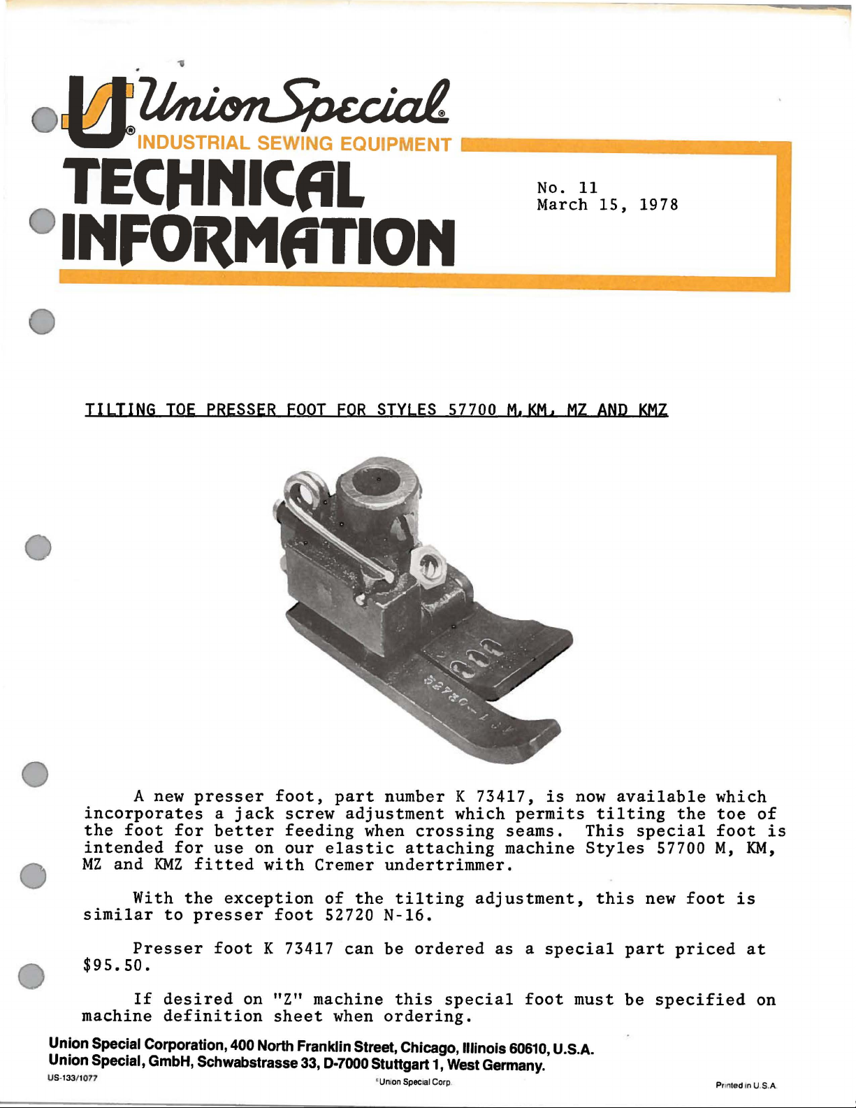
TILTING
TOE
PRESSER
FOOT
FOR
STYLES
57700
No. 11
March
M•KM•
MZ
15,
AND
1978
KMZ
A
new
presser
incorporates
the
foot
intended
MZ
and
KMZ
With
similar
$95.50.
machine
Union Special Corporation, 400 North Franklin Street, Chicago, Illinois
Union
US-133/ t
Special, GmbH, Schwabstrasse 33, D-7000 Stuttgart 1, West Germany.
On
to
Presser
If
desired
definition
for
for
fitted
the
presser
a
better
use
exception
foot
foot,
jack
on
with
foot
K 73417
on "Z"
sheet
part
screw
feeding
our
elastic
Cremer
of
52720
machine
when
number K 73417,
adjustment
when
the
can
crossing
attaching
undertrimmer.
tilting
N-16.
be
ordered
this
ordering.
' Unton Specllll Corp
special
which
machine
adjustment,
as a special
is
permits
seams.
foot
60610,
U.S.A.
now
tilting
This
Styles
this
must
available
the
special
57700
new
foot
part
be
priced
specified
which
toe
of
foot
M,
KM,
is
at
on
Pflnted In U.S.A.
is
Page 4

..
.
Page 5
IDENTIFICATION
OF
MACHINES
Each
the
machine.
numbers
"Style
changes
number.
Union
have
57700
are
Example:
Styles
which
57700
junction
differs
11
•
This
catalog
therewith.
57700 L are
ference
the
part.
number
Any
description
part
column
Advanced
Bearing
number
when
High
Needle
Mechanism,
Filtered
ings
Travel,
pared
for
for
Oil
Feed
Double
use
Tensions,
Special
Style
one
or
KL".
made
of
machines
from
is a supplement
illustrated.
and
part
under
in
the
ordering
Speed,
Bar
Single
Return
Bar
Disc
with
Knee
Maximum
machine
numbers
more
Special
are
letters
Style
in a standard
"Style
57700
similar
the
Style
number,
APPLICATION
Only
that
the
the
parts
At
the
on
the
opposite
is a component
description
second
repair
Two
Drive,
column,
parts.
and
Light
Reservoir,
Pumps
and
for
Feed
Take-up.
Press
Work
Space
is
identified
classified
suffixed,
numbers
machine,
KLZ".
in
construction
to
found
back
page
of
STYLES
Three
Weight
Enclosed
Head
Rocker
Large
for
Presser
to
Right
as
but
contain
a
in
that
OF
Catalog
on
Styles
are
illustrations
the
of
another
the
assembly
never
OF
use
MACHINES
Needle,
Presser
Positive
and
Base,
Shafts,
Handwheel
Foot
of
Needle
by a Style
standard
never
contain
the
"Z"
is
are
it
contains
CATALOO
No.
131 M
57700
part
number
part
the
One
Looper,
Needle
Greased
and
Lifter,
number
and
special.
the
letter
suffixed
grouped
no
letters.
and
KL
and
identifying
and
is
indicated
or
base
reference
Medium
Bar
and
Automatic
Bearings
and
Sealed,
Improved
Equipped
Bar 8 1/4
on a name
Standard
letter
"Z"
to
When
the
"Z".
only
Standard
under a Class
Example:
should
KM,
be
but
the
used
not
parts
description
by
indenting
part.
Always
number
in
Throw,
Needle
Bar
Lubricating
and
Bronze
Lateral
Belt
with
Guard.
Disc
Inches.
plate
on
Style
Example:
minor
Style
number
"Class
in
con-
on
Style
by
re-
identifies
its
use
the
the
first
Needle
Driving
System,
Bear-
Looper
Pre-
Thread
57700
KL
top
similar
gauge
needle.
57700
KM
both
with
knit
Standard
121
Each
denotes
number,
in
thousandths
the
size
needles
Two
and
bottom
operations
Nos.
Maximum
Three
top
and
ends
joined,
garments
gauge
GBS
needle.
Union
the
kind
stamped
of
number
packaged
needle
threads,
12
and
needle
bottom
and
No.
Maximum
Special
of
shank,
on
the
an
inch,
represent
and
machine,
for
on
medium
16.
Seam
recommended
machine.
threads.
to
rayon,
similar
16
only.
needle
point,
needle
shank,
midway
the
complete
sold
by
Union
equipped
with
hemming
to
medium
specification
speed
equipped
for
attaching
silk,
cotton,
operations
Seam
specification
recommended
NEEDLES
has
both a type
length,
groove,
denotes
between
symbol,
Special.
3
"KLIPP-IT"
sides
and
heavy
406-EFa-1
6000
R.
with
elastic
nylon
on
light
speed
and
largest
shank
bottoms
weight
P.
M.
"KLIPP-IT"
bands
and
wool,
to
medium
407-LSb-1
6000
size
finish
R.
number.
and
diameter
and
eye.
Collectively,
which
is
mechanism
of
bathrobes,
woven
fabrics.
inverted.
mechanism
in
garment
flat,
warped
weight
P.
M.
The
other
given
details.
of
blade,
on
that
cuts
Standard
Type
that
lengths
or
material.
inverted.
type
The
measured
the
the
label
both
and
128
GAS
cuts
ribbed
Type
number
size
type
and
of
for
or
all
Page 6
To
sample
on
label.
The
given
i
ndicated
type
numbers
sizes
have
needle,
A
complete
type
in
the
machine
are
available
needle
or
the
numbers
those
of
the
are
listed
NEEDLES
orders
type
order
of
style
recommended
recommended
promptly
and
size
would
the
needles
description.
below:
(Continued)
and
accurately
number
read:
to
needles tog
"1000
recommended
Other
produce
should
Needle
needles
the
ether
filled,
be
forwarded.
s,
for
most
with
an
Type
each
are
satisfactory
their
121 GBS,
style
available,
descriptions
empty
Use
of
package,
description
Size
machine
but
the
results.
and
a
032".
are
ones
The
the
Type
121
128
Thread
formation.
of
reputation
more
No .
GBS
GAS
Selection
should
Success
needles
than
Round
ted,
040.
Round
eye,
060, 067.
of
pass freely
in
the
packaged
for
producing
three-quarters
shank,
ball
shank,
spotted,
the
proper
operation
round
point,
round
chromium
needle
throu
of
under
our
highest
of a century.
Description
point,
chromium
point,
gh
the needle
Union
brand
quality
IDENTIFYING
short,
plated
short,
plated -sizes
size
is
Speci
al
name,
needles in
and
single
-sizes
double
determined
eye
in
machines
~,which
materials
PARTS
Sizes
groove,
groove,
032,
by
order
can
struck
025,
027,
struck
036, 040,
the
size
to
produce a good
be
secured
and
workmanship
groove,
029,
groove,
044,
of
thread
only
is
back
032,
049,
by
ed
spot-
036,
ball
054,
used.
stitch
use
by
for
a
Where
part
number.
letter
Each
it
appears.
IMPORTANT!
STYLE
Prices
ments
unless
construction
symbol
part
OF
MACHINE
are
are
forwarded
otherwise
A
part
which
number
strictly
directed.
permits,
too
small
distinguishes
represents
ON
ALL
FOR
net
f.
o.
ORDERS,
WHICH
cash and
b.
shipping point.
A
each
for
its
it
from
the
PART
char
ge is made
Union
complete
same
TERMS
are subject
Special
another
part,
PLEASE
IS
ORDERED.
Parcel
4
catalog
part
regardless
INCLUDE
to
to
cover
part
chan
Post
is
stamped
stamping
similar
ge
the postage a
in
of
the
PART
without
shipment
with
its catalog
is
identified
appearance.
catalog
NUMBER
notice.
s ar e
nd insurance.
in
All ship-
which
AND
insur
by
ed
a
Page 7
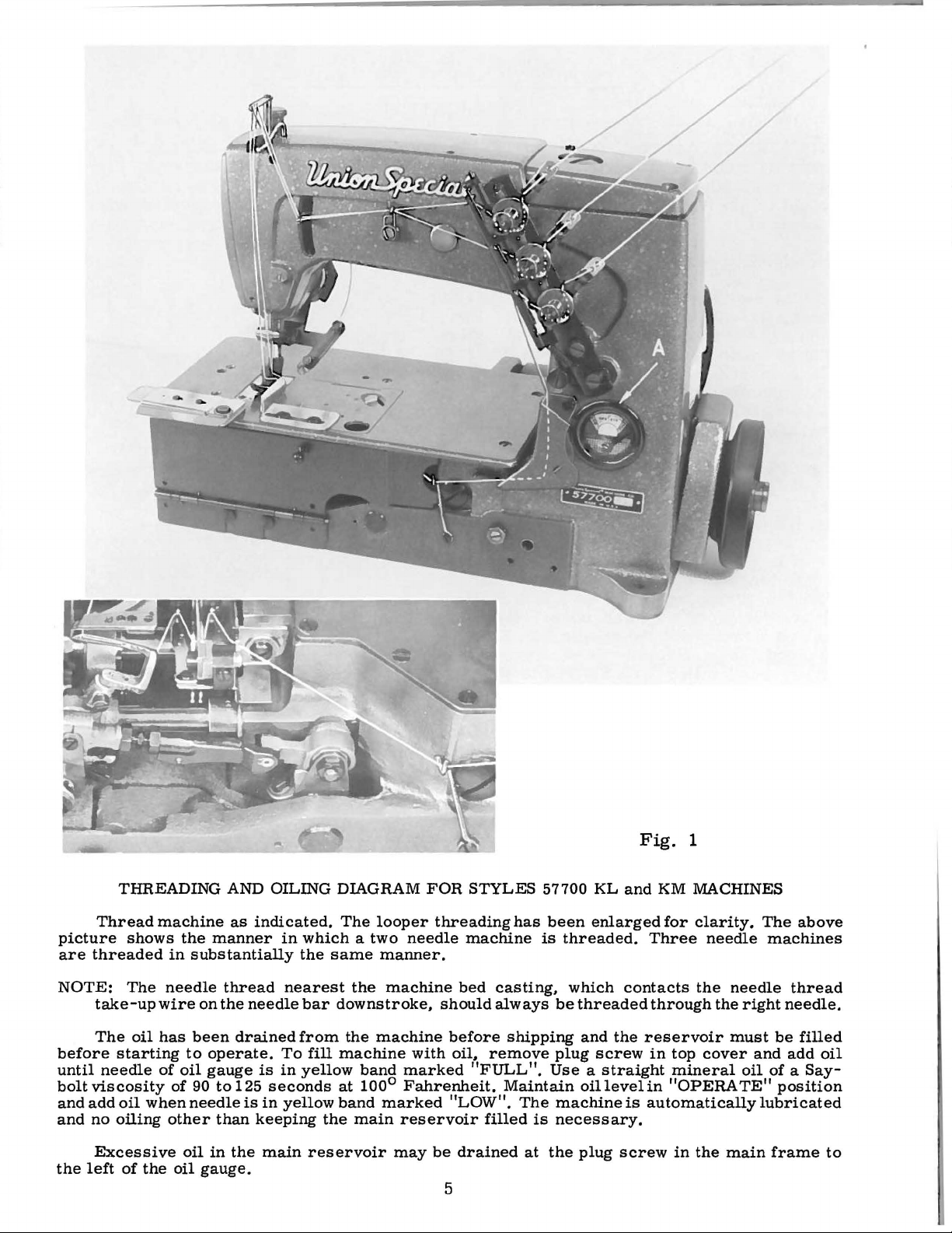
Fig.
1
THREADING
Thread
picture
are
threaded
NOTE:
take-up
The
before
until
bolt
andaddoil
and
the
starting
needle
viscosity
no
oiling
Excessive
left
machine
shows
in
The
needle
wire
oil
has
of
of
whenneedleisin
other
of
the
oil
AND
as
indicated.
the
manner
substantially
thread
on
the
needle
been
drained
to
operate.
oil
gauge
90
to
125
than
oil
in
the
gauge.
OILING
in
which a two
the
nearest
bar
from
To
is
in
yellow
seconds
yellow
keeping
main
DIAGRAM
The
same
the
downstroke,
the
fill
machine
band
at
100°
band
the
main
reservoir
FOR
looper
needle
manner.
machine
machine
with
marked
Fahrenheit.
marked
reservoir
may
STYLES
threading
machine
bed
should
before
oil,
remove
"FULL".
"LOW".
filled
be
drained
57700
has
is
casting,
always
shipping
Maintain
The
is
at
been
be
plug
Use a straight
machineis
necessary.
the
5
KL
enlarged
threaded.
which
threaded
and
the
screw
oillevelin
plug
screw
and
KM
MACHINES
for
clarity.
Three
contacts
through
reservoir
in
automaticallylubricated
needle
the
top
cover
mineral
"OPERATE"
in
the
needle
the
must
main
The
right
and add
oil
above
machines
thread
needle.
be
filled
oil
of a Say-
position
frame
to
Page 8
INSTRUCTIONS
LUBRICATION
FOR
MECHANICS
CAUTION!
reservoir
before
the
beginning
oil
to
Oil
must
the
various
damage.
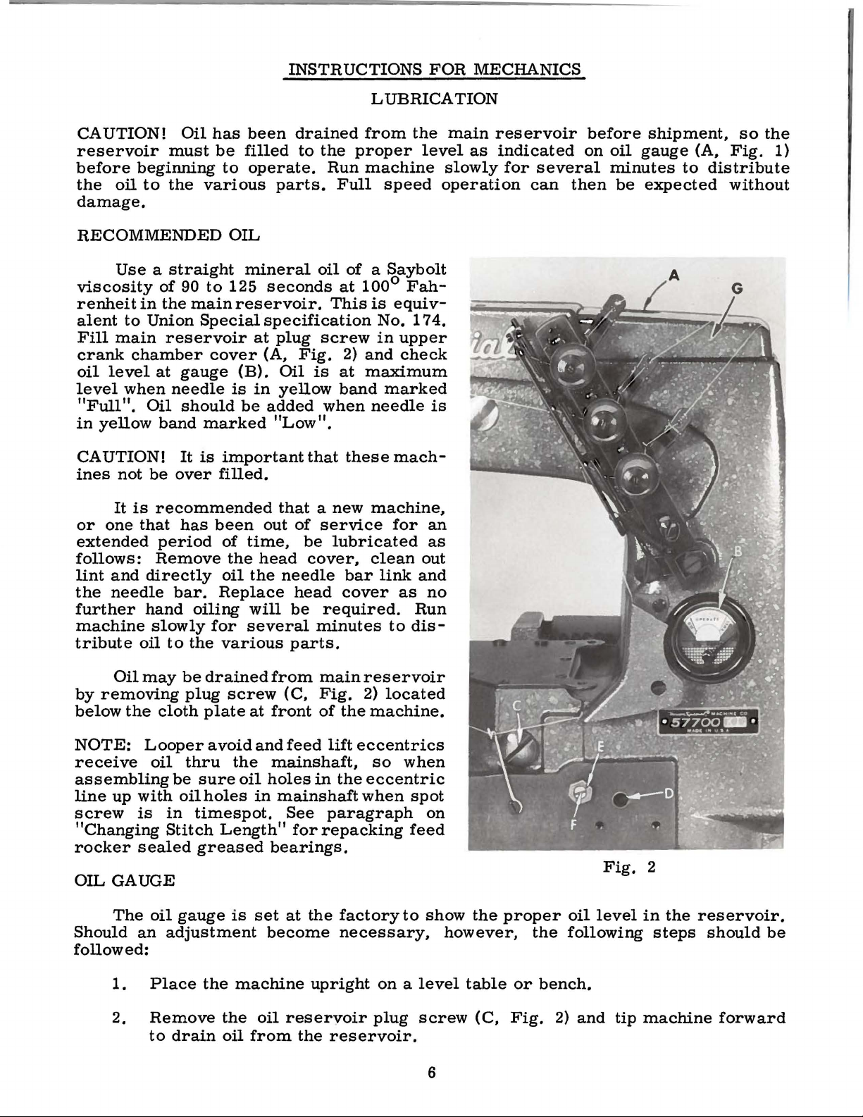
RECOMMENDED
Use a straight
viscosity
renheit
alent
Fill
main
crank
oil
level
level
"Full".
in
yellow
CAUTION!
ines
It
or
one
extended
follows:
lint
and
the
needle
further
machine
tribute
of
in
the
to
Union
reservoir
chamber
at
gauge
when
Oil
needle
should
band
It
not
be
over
is
recommended
that
has
period
Remove
directly
bar.
hand
slowly
oil
to
90
to
main
Special
cover
marked
is
oiling
for
the
has
been
be
filled
to
operate.
OIL
mineral
125
seconds
reservoir.
specification
at
(A,
(B).
is
in
be
added
important
filled.
been
of
the
oil
out
time,
head
the
Replace
will
several
various
drained
to
the
Run
parts.
Full
oil
of a Saybolt
at
This
plug
screw
Fig.
Oil
is
yellow
2)
at
band
when
"Low".
that
these
that a new
of
service
be
lubricated
cover,
needle
head
be
bar
cover
required.
minutes
parts.
from
the
proper
machine
speed
100°
and
is
No.
in
Fah-
equi
174.
upper
check
maximum
marked
needle
mach-
machine,
for
clean
link
as
to
dis-
main
level
slowly
operation
v-
is
an
as
out
and
no
Run
reservoir
as
indicated
for
several
can
before
on
then
shipment,
oil
gauge
minutes
be
expected
(A,
to
A
so
the
Fig.
distribute
without
1)
Oil
may
by
removing
below
NOTE:
receive
the
Looper a void
oil
assembling
line
up
with
screw
is
"Changing
rocker
OIL
Should
sealed
GAUGE
The
oil
an
followed:
1.
Place
2.
Remove
to
be
drained
plug
cloth
plate
thru
be
sure
oil
holes
in
timespot.
Stitch
Length"
greased
gauge
adjustment
the
the
drain
oil
from
screw
at
front
and
the
mainshaft,
oil
holes
in
mainshaft
bearings.
is
set
become
machine
oil
from
main
(C,
Fig.
of
the
feed
lift
in
the
See
paragraph
for
repacking
at
the
factoryto
necessary,
upright
reservoir
the
reservoir.
reservoir
2)
located
machine.
eccentrics
so
when
eccentric
when
spot
on
feed
show
on a level
plug
screw
the
however,
table
(C,
6
proper
the
or
bench.
Fig.
Fig.
oil
level
following
2)
and
in
tip
machine
2
the
steps
reservoir.
should
forward
be
Page 9
3.
4.
5.
6.
7.
8.
Make
Remove
Fill
press
Loosen
or
"LOW".
Tighten
Add
"FULL".
sure
main
shaft
right
oil
all
lower
reservoir
bushing
lock
until
lock
so
that
oil
nut
the
nut
is
crank
(E)
gauge
(E)
gauge
OIL
GAUGE
drained
chamber
to a level
(D,
Fig.
on
calibrating
needle
and
replace
needle
from
cover,
2).
rests
rests
(Continued)
main
even
screw
plug
in
with
in
screw
the
located
the
reservoir.
the
(F),
and
middle
(C).
middle
at
the
bottom
turn
of
the
of
the
back
contour
the
screw
yellow
yellow
of
the
of
band
band
machine.
the
knee
to
the
left
marked
marked
Align
and
test
Machine
Style
57700
KL-12
Fig.
the
plate
3
needle
of
the
bar
right
Test
698
ing
below
wardly
wall
oiler
ALIGNING
(A,
gauge.
Plate
No.
BB-12
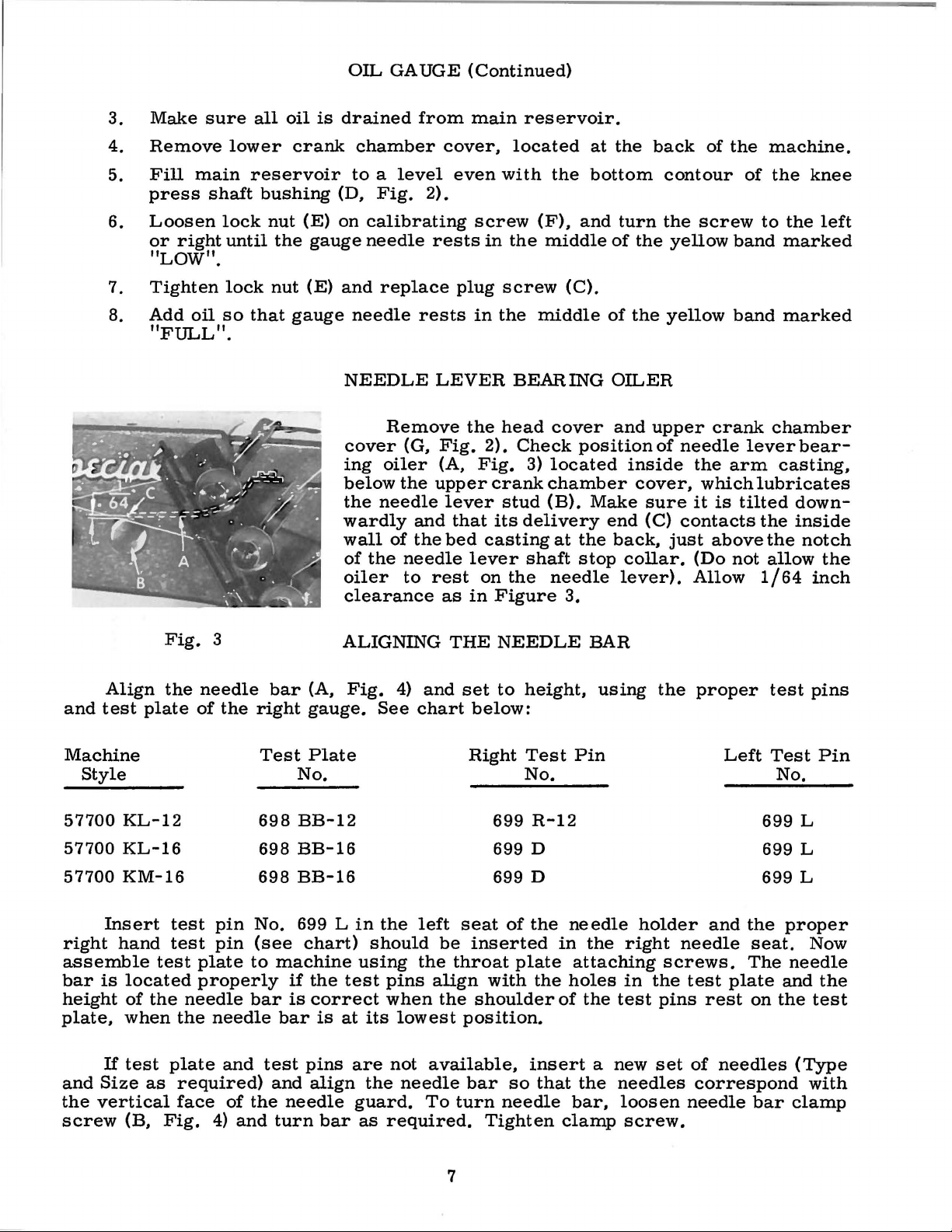
NEEDLE
Remove
cover
the
of
clearance
Fig.
oiler
the
needle
of
the
needle
4)
See
(G,
and
the
to
LEVER
Fig.
(A,
upper
lever
that
bed
rest
as
THE
and
chart
the
2).
Fig.
crank
its
casting
lever
on
in
Figure
NEEDLE
set
to
below:
Right
699
BEARING
head
stud
cover
Check
3)
located
chamber
(B).
delivery
at
shaft
the
needle
height,
Test
No.
R-12
3.
OILER
and
positionof
inside
cover,
Make
the
stop
BAR
Pin
end
back,
collar.
lever).
using
sure
(C)
upper
needle
contacts
just
the
crank
the
arm
which
it
is
above
(Do
not
Allow
proper
Left
chamber
leverbear-
casting,
lubricates
tilted
the
the
allow
1/64
test
Test
No.
699
downinside
notch
L
the
inch
pins
Pin
57700
57700
right
assemble
bar
height
plate,
and
the
screw
KL-16
KM-16
Insert
hand
is
located
of
the
when
If
test
Size
as
vertical
(B,
test
test
test
plate
properly
needle
the
plate
required)
face
Fig.
pin
No.
pin
(see
to
bar
needle
and
of
the
4)
and
698
BB-16
698
BB-16
699 L
chart)
machine
if
is
bar
test
and
needle
turn
the
test
correct
is
at
pins
align
bar
in
the
should
using
pins
when
its
are
not
the
guard.
as
required.
left
be
the
align
the
lowest
available,
needle
To
699 D
699 D
seat
inserted
throat
with
shoulder
position.
bar
turn
Tighten
7
of
the
plate
the
insert
so
that
needle
in
of
clamp
needle
the
right
attaching
holes
bar.
the
a
the
in
test
new
needles
loosen
screw.
holder
needle
screws.
the
pins
set
and
the
seat.
The
test
plate
rest
on
of
needles
correspond
needle
bar
699 L
699
L
proper
needle
and
the
(Type
clamp
Now
the
test
with
Page 10

SYNCHRONIZING
LOOPER
AND
NEEDLE
MOTIONS
Insert
wheel
(A,
of
with
in
Fig.
rightneedle
respect
reverse
left
and
motions
with
ation
eye
of
the
pulley
respect
of.
the
looper
Moving
Moving
stud
(D,
rear
is
Fig.
(away
hammer,
move
plate,
oil
drive
is
up
stud,
stud
throat
reservoir
lever
required.
the
end
tighten
the
looperin
operating
5),
moving
(B).
to
the
looper
direction
is
even
until
with
synchronize,
to
the
005
inch
is
needle
is
drive
it
in
turned
shaft
the
opposite
of
the
to
looper
accomplished
5)
of
the
from
directly
on
forward
plate
back
rocker
Then,
play
between
the
looper
the
looper
direction
to
the
Note
until
left
theheight
point,
the
looper
the
left
the
height
looper
point
allowable.
the
in
point
the
of
operating
synchronizing
direction
drive
as
follows:
looper
drive
operator),
the
stud,
(toward
support,
cover,
shaft,
using
operator),
oil
then, a light
toward
the
the
looper
drive
is
then
point
side
of
will
If
the
looper
lever
Loosen
lever.
a
light
is
all
reservoir
the
looper
lever
rocker
the
point
even
with
ofthe
turn
again
of
the
the
eye
be
the
the
distance
direction,
stud
acts
the
shaft
To
tap
that
remove
operator,
drive
drive
on
the
and
turn
of
the
the
left
eye
ofthe
handwheel
moves
right
of
needle.
the
same. A vari-
from
is
greatest
move
(C)
to
the
reverse.
synchronizing
the
clamp
move
with
is
a
required.
the
top
cover
tap
on
the
is
lever
lever
rocker
shaft,
hand-
looper
side
needle
in
to
needle
when
rear.
screw
stud
small
cloth
and
looper
all
that
to
take
using
the
the
If
the
the
to
To
shaft
screw
and
(D,
Fig.
its
Fig.
4
synchronizing
5).
Fig.
5
With
extreme
travel,
the
looper
ing,
21227
Fig.
gauge
The
check
centerline
connecting
using
CX.
5)
over
left
should
right
side
rocker
ment
the
is
clamp
position
1
eve
r (
Tighten
gauge
ting
is
can
scale.
tween
looper
the
rocker
centerline
lever
inches
stud
(Fig.
the
looper
right
the
of
gauge
Remove
and
place
threaded
end
of
locate
of
cone
(F).
necessary,
screw
the
looper
G)
as
clamp
not
available,
be
checked
The
distance
centerline
cone
of
should
6).
at
end
of
location
the
rod
bear-
nut
hole
the
gauge
against
the
looper
If
adjust-
loosen
(D)
andre-
required,
screw.
with
of
and
the
looper
be 4 1/16
the
its
of
right
No.
(E,
in
stud.
the
drive
If
set-
a
be-
the
the
8
Page 11

SETTING
THE
LOOPER
Fig.
6
Insert
right
needle
specified.
3/16
looper
from
(B)
3/16
farthest
er
used
inch,
(A,
the
to
the
inch,
position
gauge
advantageously
adjustment.
for
needle
ting
and
the
various
adjustment
(C)
(it
has a left
nut
(D)
on
the
connecting
ward
ion.
(D),
left
tion
to
obtain
Retighten
then
ball
and
does
ment.
a
new
seat,
If
the
for
example,
Fig.
center
6)
of
point
when
the
to
No.
21225-3/16
Refer
type,
looper
looper
gauge
styles
is
required,
connecting
rod
the
both
nut
(C).
joint
is
not
needle
type
looper
so
the
the
of
the
looper
the
right.
in
to
of
machines.
hand
rod
forward
3/16
inch
nuts,
Make
in
vertical
bind
after
in
and
size
gauge
set
distance
right
needle
looper
is
can
making
chart
gauge
number
loosen
thread)
(E),
or
dim
first
sure
adjust-
the
as
is
the
is
at
its
Loop-
be
this
below-
set-
for
If
nut
and
turn
back-
ens-
nut
the
posi-
Machine
Styles
57700
57700
57700
moves
brushes,
Fig.
screw
KL-12
KL-16
KM-16
The
looper
to
the
but
If
adjustment
6)
and
clockwise
turn
counterclockwise
front
Tighten
adjustment.
while
lock
making
screw
Now
seat.
SETTING
On
is
correct
underside
left
side
dimension
loosen
down
not
to
needle
HEIGHT
Style
of
screw
as
required
disturb
bar
57700
when
the
of
should
the
either
is
left,
does
stop
sets
acts
insert
OF
the
looper
the
left
be
(B,
Fig.
and
alignment
up
Needle
Type
128
128
121
set
correctly
behind
not
pick
is
necessary,
screw
the
the
this
when
NEEDLE
KL,
the
top
(B),
needle.
1/64
4)
retighten
or
down.
GAS
GAS
GBS
the
needle,
at
the
(G)
looper
reverse.
adjustment
setting
another
height
of
its
with
the
inch.
and
If
move
screw.
of
the
in
line-of-feed,
rear
loosen
as
required.
to
the
Holding
is
obtained
needle
BAR
of
the
eye
is
looper
On
Style
adjustment
needle
needle
its
of
rear
may
in
needle
3/64
point
Care
bar
Looper
Setting
3/16
3/16"
point
the
lock
Turning
and
looper
prove
and
the
inch
flush
57700
is
bar
should
when
Gauge
7/32"
11
if,
(A,
Fig.
needle
screw
turning
to
helpful.
recheck
left
needle
(A,
Fig.
below
with
KM,
necessary,
(A)
up
be
taken
moving
as
(B).
(F,
stop
the
the
the
the
this
the
it
7)
it
8)
or
Looper
Number
21225-7/32
21225-3/16
21225-3/16
Fig.
7
Gauge
9
Page 12

SETTING
HEIGHT
OF
NEEDLE
BAR
(Continued)
NOTE:
bar.
right
descending
back
SETTING
(B)
the
approximately
are
travel.
feed
to
hold
and
the
CAUTION:
looper.
The
All
and
of
the
Set
so
there
tips
parallel
Adjust
dog,
feed
If
feed
turn
front
needles
left
looper.
THE
the
of
the
to
screw
teeth.
height
are
sides
needles
FEED
feed
is
maintain
dog
dog
See
dog
equal
teeth
3/64
with
the
in
teeth
(D)
Retighten
that
should
of
must
inch
the
supporting
position.
clockwise
there
be
to
have
needle
be
DOG
(A,
Fig.
clearance
extend
above
throat
this
setting.
are
not
nut
is
right
slots
the
sufficient
if
equal
deflected
plate
parallel
to
when
in
9)
in
on
all
depth
the
screw
Screw
lower
clearance
feed
test
plate
throat
alike
the
throat
sides.
of a tooth
throat
at
high
(C),
with
the
dog
space
plate.
See
plate
point
under
(D)
is
the
front
is
between
and
on
The
on
plate
that
and
used
throat
teeth
set
test
pins
the
the
or
of
the
plate,
and
properly.
underside
were
counterclockwise
used
loosen
of
feed
to
Fig.
nut
dog
align
8
(C,
to
and
needle
Fig.
raise
top
8)
of
Fig.
Should
move
backward,
clamps
the
feed
ward
nut.
CHANGING
length.
by
Fig.
thread)
regulating
stitch
the
the
feed
Set
loosening
rocker
rocker
as
needed
the
This
10)
(it
on
adjusting
9
it
be
feed
dog
loosen
feed
forward
STITCH
stitch
is
the
has
the
end
stud
and
or
rocker
rocker
sure
this
ion
of
stitch
necessary
forward
nut
(E)
which
rocker
and
and
to
accomplished
locknut
a
of
screw
arm
move
or
back-
retighten
LENGTH
required
left
the
turning
hand
stitch
(G)
Should
right,
(B)
to
the
adjustment.
When
the
feed
the
throat
length.
to
or
to
the
(F,
the
lo-
it
loosen
onto
desired
feed
the
dog
be
necessary
screws
the
feed
position
rocker
handwheel
plate
arm
should
slots
(A,
rocker
is
have
with
to
move
Fig.
and
(D)
does
turned
equal
feed
Fig.
the
feed
10)
which
shaft
retighten
(C)
not
bind
in
the
clearance
travel
10
dog
hold
and
move
screws.
after
operating
on
both
set
to
to
the
the
making
direct-
desired
left
feed
feed
Make
ends
10
Page 13

CHANGING
STITCH
LENGTH
(Continued)
cated
marked
stitch
under
with
regulating
lengthens
locknut
be
Start
beari~s
under
securely.
pressed
tapered
to
Setting
the
"L"
the
stitch
Fig.
in
flush
end
prevent
the
left
and
stud
11
of
Feed
end
of
"S".
toward
(moves
with
the
shaft
damage.
Dog".
the
cloth
Turning
the
stitch
casting.
first,
Check
Also
plate
the
'S")
screw
and
in
turning
regulating
Any
change
corresponding
setting.
The
feed
cation
be
10)
(D)
screws
shaft
Allen
or
repair
accomplished
and
remove
from
(A)
(C).
The
screw
bearings.
When
clean
the
can
Greased
If
twisting
and
tube
be
grease
To
for
proper
check
grease
to a void
supplied
bearings
sealed
assemble,
slightly
to
the
head
clockwise
it
stud
in
change
rocker
after
nut
machine
and
remove
shaft
(J)
and
packing
bearings
adjustment
see
that
of
the
main
shortens
shaft
the
in a counterclockwise
toward
stitch
as
follows:
(F).
by
can
remove
the
should
contamination.
under
are
reverse
when
there
the
length
in
the
assembly
years
of
Remove
rocking
stop
now
shaft
bearings,
be
applied
the
part
located
are
the
entering
of
feed
is
no
"L").
will
rear
may
operation.
Loosen
feed
slightly.
collar
be
withdrawn.
(K). Now,
the
Tube
number
at
(L,
replaced
above
the
dog
binding
(H),
which
stitch
(moves
direction
Retighten
necessitate
needle
require
This
nut
(E,
rocker
on
right
Loosen
parts
must
directly
of
2 860 4
M,
Fig.
they
procedure.
grease
as
described
at
any
is
the
guard
lubri-
can
Fig.
arm
Loosen
end
of
repack
be
from
grease
P.
10).
should
sealed
point.
a
SETTING
Set
it
does
at
is
permissible.
its
until
the
loosen
screw.
turn
not
its
most
vertical
the
needle.
screw
To
screw
clockwise
erly
set.
NOTE:
needle
A
guard
SETTING
On
Style
back
set
toward
toward
the
the
THE
the
rear
quite
forward
face
point
To
raise
(G)
to
raise
change
FRONT
the
front
path
REAR
needle
contact
It
should
approach
of
the
move
(F),
move
or
clockwise
it.
in
setting.
NEEDLE
57700
path
needle
of
the
NEEDLE
guard
the
point
looper
needle
needle
lower
Retighten
stitch
KL,
of
set
the
guard
looper
(E,
rear
of
travel.
be
set
within
(B).
guard
guard
needle
to
lower
screw
length
GUARD
the
looper
so
as
GUARD
Fig.
of
the
A
as
low
about
moving
forward
as
guard,
needle
will
require a change
front
as
it
that
it
it
moves
8)
horizontally
right
clearance
as
possible,
3/64
to
the
or
inch
backward,
required
loosen
guard
(F)
after
needle
moves
pushes
behind
needle
of.
of
left,
is
and
screw
or
guard
guard
behind
the
the
so
(A)
005
yet
the
needle,
even
merely
retighten
(F)
counter-
is
prop-
in
so
that
the
left
and
needles.
that
when
inch
have
with
and
rear
it
pushes
needle.
"center
The
On
looper
Style
Fig.
the
12
left
57700
needles",
may
needle
KM,
back
brush
11
Page 14

but
not
vertical
side
of
guard
loosen
To
raise,
tighten
pick
face
the
or
right
screws
lower
screws
at
push
left
SETTING
the
left
the
needle.
needle
(A,
Fig.
or
after
needle.
left
The
at
11),
rotate
guard
FRONT
needle
front
any
needle
is
It
should
until
needle
time.
move
needle
guard,
properly
NEEDLE
be
the
guard
To
move
guard
loosen
set.
GUARD
set
point
should
guard
as
of
the
forward
as
required
screws
(Continued)
low
as
possible,
looper
not
contact
or
and
(B),
is
just
the
backward,
retighten
move
yet
past
rear
guard
have
the
its
left
needle
merely
screws.
and
re-
NOTE:
A
change
setting.
THREAD
The
TENSION
thread
correctlywhen
the
presser
inch
tirely
has
tension
12),
and
of
the
released
reached
If
adjustment
release
located
move
tension
required.
adjustment
at
any
point.
SETTING
The
Fig.
lifter
1/16
(D,
Fig.
lever
down
height
4)
is
lever
inch
4)
is
released
below
HEIGHT
set
clearance
in
tension
it
begins
foot
is
raised
end
ofits
when
its
highest
lever
at
the
back
Retighten
there
should
of
the
correctly
(B,
Fig.
and
the
and
the
throat
stitch
RELEASE
release
to
to
travel
the
presser
position.
is
needed,
screw
of
the
disc
separator
screw.
be
OF
PRESSER
presser
if
12)
is
between
bottom
the
presser
plate.
length
is
function
within
and
is
loosen
(A,
machine
After
no
binding
BAR
bar
it
is
possible
fully
lower
surface
will
NOT
set
as
1/8
en-
foot
Fig.
as
(C,
depressed.
surface
of
head
foot
resting
require
to
remove
of
opening
Also
the
on
a
change
the
presser
there should
presser
in
the
the
throat
in
Fig.
bar
bed
plate,
front
needle
13
foot
when
be
approximately
connection
when
the
with
the
the
and
foot
feed
guard
foot
guide
lifter
dog
If
adjustment
bar
is
in
on
the
throat
driver
to
handwheel
removed
SETTING
Set
the
bar
thread
the
needle
Lower
Set
the
this
needle
attaching
the
low
plate
obtain
so
as
mentioned
needle
eyelet
bar
setting
screw
is
position.
the
that
needle
NEEDLE
(B),
thread
thread
(Fig.
needed,
turn
Loosen
surface,
1/16
inch
pry
setting
bar
in
previous
THREAD
thread
so
that
eyelet
take-up
when
for a smaller
frame
13),
eyelet
on
Style
handwheel
screw
up
is
in
paragraph.
wire
its
upper
the
needle
(E).
presser
and
tighten
its
high
TAKE-UP
(A,
surface
needle
thread
(C)
so
that
57700
KL;
in
operating
Then,
bar
connection
screw
position
WIRE
Fig.
13),
is
bar
has
loop
the
7/8
even
eyelet
inch
THREADING
Draw
piece
of
the
fabric.
looper
Refer
and
to
needle
threads
threading
into
diagram
the
(Fig.
machine
1)
machines.
12
direction
while
and
(E).
AND
holding
Check
see
FRAME
located
with
completed
and
raise
hole
on
Style
and start
for
manner
and
guide
if
presser
adjacent
the
its
it
is
57700 KM.
until
presser
the
foot
with a screw-
setting
by
foot
EYELET
to
the
top
of
the
downward
for a larger
3/4
inch
above
operating
of
threading
needle
down
turning
can
needle
holes
stroke.
loop.
on
these
be
in
the
a
Page 15

be
The
set
looper
to
compensate
thread
for
SETTING
take-up
varying
LOOPER
is
not
spotted
conditions.
THREAD
on
the
It
is
set
is
just
take-up
are
clearly
of
the
in
slot
plate
TAKE-UP
main
correctly
support.
shaft
cast
when
visible
looper.
of
cast-off
when
off
the
This
and
consequently
the
the
highest
points
below
should
plate
looper
of
the
the
underside
be
and
can
thread
lobe
needles
centered
cast-off
of
I
I
I
0 -
1
'----
should
The
39/64
---
be
length
inch
made
(See
---
in
of
Fig.
--
Fig.
ADJUSTMENT
the
following
stroke
14).
14
- ·
--
of
the
Loosen
c
--
sequence:
OF
CUTTING
armature
screw
B
(A,
PRESSER
Regulate
gulating
exerts
presserfoot
ly
when a slight
the
fabric.
located
in
the
clockwise
counterclockwise
With
connections
SOLENOID
shaft
(A,
Fig.
Fig.
23)
FOOT
the
screw
only
directly
head
ADJUSTING
all
14)
when
(D,
enough
to
feedthe
This
is
behind
of
the
increases
MECHANISM
of
disconnected,
STROKE
should
making
PRESSURE
presser
Fig.
pressure
workuniform-
tension
the
knurled
the
machine.
the
acts
"KLIPP-IT"
the
electrical
be
approximately
this
spring
13)
so
that
on
is
placed
screw,
needle
Turning
pressure,
the
reverse.
plug-
adjustments
adjustment
re-
it
the
on
bar
it
f3/"
764
to
be
sure
to
operate
position
(D)
to
the
in
is
that
one
by
right
Fig.
solenoid
direction
the
or
15
spring
left
is
bottoming.
only,
loaded
on
shaft
when
shaft
(B)
Since
actuated,
(B,
to
obtain
13
the
Fig.
desired
armature
its
only
14).
Loosen
C A
of
the
means
dimension.
of
nut
8
Fig.
solenoid
returning
{C)
and
Retighten
16
is
to
move
designed
its
rest
head
nut
(C).
Page 16

The
support
looper
(A,
Fig.
height
15)
should
when
ADJUSTING
be
set
3/64
at
its
extreme
LOOPER
inch
left
position.
HEIGHT
below
the
surface
of
the
throat
plate
With
shaft
pass
required,
retighten
(A,
the
the
needles
Fig.
looper
loosen
screws.
14).
(B)
in
On
the
along
screws
With
ADJUSTING
up-position,
forward
edge
the
(A,
lower
(C)
Fig.
SEVERING
slowly
motion,
for
approximately
17)
reposition
knife
at
the
its
DEVICE
depress
tip
of
lower
extreme
the
7/16
the
lower
knife
left
cutting
knife
inch.
Should
(B)
position,
solenoid
(A,
Fig.
adjustment
as
necessary
cutting
armature
16)
must
be
and
edge
(C)
for
the
of
the
ring
Replace
(E)
.004
needle's
needles.
and
snap
Fig.
threads
Should
rotate
ring
"
18
must
adjustment
connecting
and
tighten
B
be
"X"
be
rod
(F)
lock
nut.
the
should
the
adjustment
knife
be
rechecked
through
and
swinging
looper
Fig.
inch
required,
as
With
lower
be
looper
carrier
The
the
deflect
thread
17
(See
the
knife
approximately.
basic
in.
Fig.
loosen
necessary
looper
in
(A,
Fig.
is
necessary,
bracket
ADJUSTING
adjustment
to
assure
needle
the
looper
As
the
must
17)
at
approximately
thread
be
to
locknut
to
obtain
extreme
004
18)
at
point
that
thread
lower
caught
"X"
12
ga.
16
ga.
the
inch
and
CAREFULLY
KNIVES
outlined
the
loops
(C)
knife
left
(D),
the
left
15
clearance
plate
(G,
lower
(A & B,
by
by
cutting
7/64
5/64
of
"X"
~osition,
f 3 2
Fig.
in
swings
11
11
the
centerline
remove
dimension.
inch.
spring
BEND
17)
Fig.
knife
edge
snap
swing
There
between
(B).
to
suit.
16
must
passes
Fig.
(D)
while
out,
edge
(E),
If
the
19)
the
14
Page 17

the
needle
Should
as
described
threads
correction
for
be
Fig.
ADJUSTING
caught
required
17.
by
cutting
to
meet
KNIVES
edge
this
(F)
condition,
(Continued)
and
drawn
increase
back
dimension
to
the
uR.per
'X"
knife.
slightly
NOTE:
apply
The
figures
to a three
shown
needle
are
machine.
for a two
A
needle
machine,
however,
the
same
would
To
avoid
the
edge
at
point
the
screws
spring
the
upper
lower
Adjustment
(C)
(D).
overlapped
left
interfering
spring.
ment
must
fere
severing
(C).
corner
(G),
as
With
knife
and
repositioning
Retighten
With
end
position
With
of
the
be
taken
with
pinching
of
the
lower
Tip
of
the
reposition
required.
both
knives
knife
reference
the
device
(B)
can
by
with
any
plate
to
feed
(A,
screw.
the
the
knife
(D)
of
the
upper
approximately
be
plate
to
the
adjustment
spring
assure
dog
in
knife
upper
Retighten
in
their
Fig.
21)
made
the
to
Fig.
spring
prevent
front
that
(F)
rest
position
by
hexagonal
(E,
by
Fig.
needle
and
must
18,
face
it
maintaining a minimum
threads
the
plate
cutting
(E)
at
point
knife
screws.
resting
overlap
.
020
loosening
stop
the
at
its
the
looper
of
requiring
Fig.
does
21),
not
(See
edge
and
position,
looper
extreme
the
move-
inter-
Fig.
as
spring
of
(F).
plate
the
inch.
screw
plate
is
from
plate
care
21).
19
the
the
lower
(B)
lower
Adjustment
While
knife
must
knife
of.
in
020
this
(A,
Fig.
be
in
alignment
must
can
be
Fig.
inch
position,
20)
be
overlapped
made
clearance,
by
20
a
clearance
swings
as
shown
loosening
with
out,
by
E
the
of
15
Page 18

.
020-.040
edge
of
the
inch
upper
must
knife
0
ADJUSTING
be
maintained
carrier
J
(H).
KNIVES
between
Forward
(Continued)
the
lower
or
rearward
stop
(G)
repositioning
and
the
corresponding
of
the
upper
E
.020~~
The
22)
must
plate
(C)
upper
1 o
spring
the
spring
after
knife
ope r thread
can
tension
THREAD
HOOKS AND
RELEASE
1
I
A
Fig.
looper
be
clamped
being
(D).
be
regulating
21
thread
(B)
and
severed
Tension
retaining
adjusted
PULL-OFF
TENSION
ADJUSTMENTS
(A,
between
lower
by
on
by
turning
screw
Fig.
the
knife
the
the
plate
(E).
stop
extending
ment
position
(J)
can
will
from
be
stops
lengthen
the
made
as
required
by
Fig.
or
shorten
cloth
loosening
22
after
and
the
thread
seve
ring.
screws
retighten
tails
Adjust-
(K),
re-
screws.
Loosen
23)
in
rear
(C)
tighten
tension
turning
tension
cutting
tension
t h r e
thread.
h o o k ( F ) s o t h a t t
threads
sewing
stitch.
of
in a horizontal
ad
clamp
clamp
the
clamp
disc
eccentric
is
process
discs
Adjust
are
immediately
Adjust
(B)
machine
screw.
separator
released
begins
are
p u 11 e r s
thread
long
thread
screw
located
and
position,
Adjust
(E)
so
as
soon
open
begin
he
enough
on
(A,
at
set
lever
(D)
that
as
and
before
pulling
pull-off
needle
to
start
the
pull-off
Fig.
the
re-
the
by
the
the
that
next
16
Fig.
23
Page 19

THREAD
PULL-OFF
HOOKS AND
TENSION
RELEASE
ADJUSTMENTS
(Continued)
hook
CAUTION:
(G)
so
that
(a)
(b)
(c)
Fig.
the
Observe
cutting
Tension
with
Take
support.
24
looper
to
operation.
disc
no
bind.
care
A
thread
insure
separator
that
pull-offhooks
ADJUSTING
With
moved
wiper
piece
threads.
wiper
observing
threads
the
ing
of
must
its
hook
in
the
not
arc
(A,
and
is
clamped
ample
should
WIPER
the
power
from
solenoid,
of
fabric
Actuate
Fig.
that
must
wiper
of
be
of
the
caught
contact
travel.
when
securely
clearance
move
do
not
THREAD
lead
the
thread
sew
and
the
thread
24)
by
the
needle
deflected
wiper
swing-
by
the
returning
the
needles
of
bottom
re-
on
sever
hand,
by
hook
after
the
freely
a
or
it
pull-off
between
on
thread
(See
Fig.
the
has
hooks
Fig.
25).
presser
been
during
tension
guide
25
The
foot
severed.
the
discs
or
guide
wiper
during
This
screws
8
condition
(A &
B,
Fig.
Fig.
26
can
c
26)
be
accomplished
and
position
the
wiper
the
screws.
be
set
least
the
wiper
through
When
position,
lever
stopped
before
solenoid
be
accomplished
ing
screw
lever
s
crew
lead
assembly.
guard
will
fabric.
Screws
so
possible
wire
its
returning
the
(A,
Fig.
by
stop
the
armature
stops.
as
required,
.
Reconnect
for
by
plate
not
Retighten
as
to
resistance
as
arc
thread
27)
(B)
(C),
thread
loosening
(C)
hook
(D)
offer
it
of
This
by
reposition
retighten
into
should
passes
travel.
to
rest
wiper
must
slightly
of
the
can
loosen-
power
wiper
so
the
to
be
Fig.
27
17
Page 20

4
]~~
6
9~
~~
45
10
11
Page 21

FEED
NEEDLE
DOGS,
BAR,
CLOTH
NEEDLE
PLATE,
BAR
HEAD,
HANDWHEEL
PRESSER
ASSEMBLY
FOOT,
AND
THROAT
MISCELLANEOUS
PLATES,
PARTS
He
No.
10
11
12
13
14
15
16
17
18
19
20
21
22
23
24
25
26
27
28
29
30
31
32
33
34
35
36
37
38
39
40
41
42
43
44
45
46
47
48
49
50
51
52
53
54
1
2
3
4
5
6
7
8
9
f.
Part
No.
22768
56958
29264
52817-16
52818-8
52842
57720
51430
22840
51430
57730
22799
57724
57705
57780
51280
57725
57725
22801
57725
52724
52724.
22526
22574
57701
56381
22845
22760
35772
51281
56958
51858
51758
23405
22726
12957
57791
56321
61321
22574
56321
56321
22894
29476
29476
22894
27-435
89
88
28
28
91
80
7205
22
660-313
87
25 c
AB
77
A
S-16
B
B
G
c
M-16
D
A
F
M-16
B
M-16
M
A
J
A
B
A
JW
P-12
P-16
c
c
D-219
B
A
H
AC
T
E
L
L
F
K
LK-062
LK-072
AA
Blk.
Description
Screw,
Needle
Needle
Needle
Presser
Throat
Feed
Screw----------------------------------------------------
Throat
Needle
Needle
Looper
Feed
per
Feed
per
Throat
Throat
Well
Screw,
Screw,
Screw,
Cloth
Cloth
Needle
Needle
Needle
Screw,
Folder,
Looper
Handwheel
Looper
Looper
for
needle
Bar
Thread
Bar
Thread
Bar
Assembly,
Needle
Needle
Set
Presser
Tilt
Lock
Presser
Hinge
Dog,
Dowel
Pivot
Dog,
inch-------------------------------------------------
Dog,
inch-------------------------------------------------
Nut
Plate
Plate
Pivot
Screw------------------------------------------------
Spring
Cloth
Screw-----------------------------------------------Spring
Retaining
Screw------------------------------------------------
Handwheel-------------------------------------------Pulley------------------------------------------------
Screw,
Set
Bar,
Bar
Spot
Set
Screw,
Set
Screw,
Needle
Screw,
Foot,
Clamp
Adjusting
Nut
Screw
Plate,
for
Plate
Pin
Guard,
Guard,
Screw
Needle
for
for
Plate,
Plate,
-------------------------------------------------
for
throat
for
cloth
for
cloth
----------------------------------------------Cover
Screw
Washer
Plate
Lever
Thread
Thread
for
No.
for
Style
Washer
Thread
Assembly
Set
Screw
Avoid
Avoid
for
Screw
bar
eyelet
Eyelet,
Eyelet
for
marked
Head
--------------------------------------
Screw
Foot
---------------------------------------------
Foot
for
Style
Support---------------------------------------
for
for
No. 12
No.
for
for
Thread
Frame
Frame
Plate
Eccentric
Eccentric
--------------------------------------------
---------------------------------------
for
for
Thread
for
middle
for
Style
Shank
Screw
--------------------------------------------
Guard
plate
plate
Cover
23405 T ------------------------------------
Guard--------------------------------------
link
-------------------------------------
Screw-----------------------------------
Bottom
-----------------------------------------Style
57700
57700
Style
Style
------------------------------------------
-------------------------------------gauge,
16
gauge,
No.
12
No.
16
plate
-------------------------------------
-------------------------------------
Assembly--------------------------------
------------------------------------------
---------------------------------------Spring-------------------------------
Eyelet,
Eyelet,
Eyelet,
57700
KM---------------------------------
----------------------------------------
--------------------------------------
---------------------------------------
--~-------------------------------------
pin
------------------------------------
-------------------------------
for
Style
57700
Lock
Washer
Style
57700
"BD-16"
outside
No.
Guide
57700
-----------------------------------
57700
57700
gauge,
gauge,
------------------------------------
Assembly,
Assembly,
needles----------------------
52842 G ------------------------
------------------------------
needle
----------------------------------
KM, 16
---------------------------
KM
KM
--------------------------teeth
KM--------------------------KL
---------------------------
Style
Style
Style
Style
for
Style
for
Style
for
Style
---------------------
KM
--------------------------
--------------------------
per
57700
57700
57700
57700
57700
57700
57700
for
Style
for
Style
KM
---------------
-------------------
inch--------------
KL,
16
teeth
KL,
16
teeth
KL
--------------
KL
--------------
KM
------------KM------------KL
-------------
57700
57700
KM
KL
--------
--------
Amt.
Req.
1
1
1
1
1
1
1
2
1
1
1
1
1
1
1
1
1
1
1
1
2
1
2
1
1
1
1
1
1
1
1
2
2
2
1
1
1
1
3
3
1
1
1
1
2
1
1
1
1
1
1
3
1
1
2
1
1
1
1
19
Page 22

35~
I
I
34~
~)I
33_?~
i
-
~·
!,......
Ll
•
20
Page 23

THREAD
WIPER
AND
KNIFE
ASSEMBLY
PARTS
Ref.
No.
1
2
3
4
5
6
7
8
9
10
11
12
13
14
15
16
17
18
19
20
21
22
23
24
25
26
27
28
29
30
31
32
33
34
35
36
37
38
39
40
41
42
43
44
45
46
47
48
49
50
51
52
53
54
Part
No.
G29906
22767
96150
998-59
1310109
99650
96707
22738
99646
28 B
60078
99646
99318
43443
99651
99648
99653
22585
94
99648
99652
G21233
99654
92
22729
99649
22849
998-243
99647
G52768
G52771
G52773
22561
G51367
G51352
43443
G51350
G660-210
99314
G52737
96275
G22561
G52749
87 u
G52774
99316
G52770
G52763
G52751
G52769
G52772
96705
G52776
E
A
D
B
z
A
Q
c
c
HE
A
A
KW
KW
KW
A
KE-020
KE
Q
KE
KW
A
KW
KW
KW
KW
KW
KW
KW
KW
Description
Thread
Washer
Upper
Hexagonal
Screw,
Washer, . 008
Connector-------------------------------------------
Nut,
Lower
Retaining
Nut------------------------------------------------Connecting
Retaining
Screw,
Lower
Screw,
Upper
Screw,
Upper
Clamp
Counter
Clamp
Carrier
Spring
Lower
Wiper
Screw,
Washer,
Terminal
Insulating
Mounting
Spring
Screw,
Ball
Screw,
Nut,
Lever
Screw,
Nut,
Bracket,
Thread
Thread
Screw,
Screw,
Thread
Washer----------------------------------------Cable-------------------------------------------
Cable
Screw,
Screw,
Holder------------------------------------------
Screw,
Rotating
Thrust
Nut,
---------------------------------------------
Knife
for
for
No.
Knife
for
Knife
for
Stop
for
Knife
Spring----------------------------------------
Part----------------------------------------
Plate-----------------------------------------
Plate
----------------------------------------------
Stop
Assembly------------------------------
for
No.
998-59----------------------------
for
No.
998-59
--------------------------------------Tube
Bracket--------------------------------
-----------------------------------------for
-------------------------------------------for
for
No.
-----------------------------------------for
for
Nos.
for
Wiper
Wiper
for
for
Wiper
Holder
for
for
for
Solenoid
Collar
for
No.
Carrier
Stop
Plate---------------------------------
No.
inch
G52737
Carrier
Ring,
Rod
Ring,
No.
--No.
Plate-------------------------------------
No.
G52770
-----------------------------------------
---------------------------------------
Plate
----------------------------------
No.
99646 A --------------------------
No.
99646 B --------------------------
22738
No.
99318,
thread
Guide,
Wire
No.
No.
Guide,
------------------------------------
No.
No.
No.
998-243
G52773
thick
for
-------------------------------------for
G52749
-------------------------------------
G52774
------------------------------------
D
99646
99651-----------------------------
99654-----------------------------
99654
99649
99650
--------------------------------
-----------------------------------
--------------------------------KW
KW
---------------------------------
No.
G51352
No.
99619-------------------------
KW
KW----------------------------
KW
--------------------------
-----------------------------
A
--------------------------
99648,
wiper
upper-----------------------
------------------------------
lower-----------------------
----------------------------
----------------------------
----------------------------
(5-40
---------------------------
------------------------------
------------------------------
---------------------------
---------------------------
99648
guide-------------------
NC-2A)
KE
--------------------
C
--------------
----------------
Amt.
Req.
1
1
1
1
1
1
1
1
1
1
1
1
1
3
1
1
1
1
1
1
1
1
3
1
1
1
2
1
1
2
1
1
1
1
1
1
1
1
1
1
1
2
2
1
2
1
3
1
1
1
1
1
1
1
21
Page 24

22
Page 25

CUTTER
SOLENOID,
CUTTER
AND
DRIVE
SOLENOID
PARTS
MOUNTING
BRACKET
Ref.
No.
1
2
3
4
5
6
7
8
9
10
11
12
13
14
15
16
17
18
19
20
21
22
23
24
25
26
27
28
29
30
31
32
33
34
35
36
37
38
39
Part
No.
92
99654
660-436
94
52882
G21233
95169
22517
80557
78056
99624
53634
9937
482
98
21657
99296
99620
22596
21657
25
99615
99613
G52882
97005
41332
96276
55235
99614
99619
99616
95168
998-306
99617
998-304
96150
22734
G21233
90
A
v
BG
A
c
AJ
AK
s
KE
J
E
A
D-4
Description
Screw,
Cable
Solenoid
Screw,
Screw,
Cable
Screw,
Screw,
Washer,
Screw,
Guide
Washer,
Nut,
Collar
Spacer,
Screw,
Tension
Screw,
Lever
Screw,
Washer,
Shaft
Mounting
Presser
Washer,
Retaining
Nut,
Rocker
LockingScrew-------------------------------------Connection-----------------------------------------
Screw,
Cutter
Bushing
Terminal
Washer,
Screw,
Cable
Screw,
for
No.
99654
Clamp
for
for
Clamp
for
for
for
Bracket--------------------------------------
for
---------------------------------------------
Screw
for
for
for
--------------------------------------------for
----------------------------------------------
for
Shaft
for
Solenoid-------------------------------------
Spacer,
for
Clamp
for
---------------------------------------
Harness
No.
99654
upper
---------------------------------------
No.
G21233
No.
G52882
for
No.
No.
99624
for
No.
No.
78056
----------------------------------------No.
G52882
No.
21657
Release
No.
No.
for
Bracket-----------------------------------
Spring-------------------------------------
for
Ring--------------------------------------
No.
No.
Block
for
No.
No.
and
99620
21657
No.
No.
99613
99619---------------------------------Connection-----------------------------
998-306
for
------------------------------------
No.
22734
998-304-----------------------------
--------------------------------------G21233
-------------------------------
-----------------------------------
-------------------------------
chamber
22517
99624------------------------------
---------------------------------
AK
Lifter
-------------------------------
AK
99613
No.
cover---------------------
BG
--------------------------
KE
--------------------------
A----------------------------
-------------------------------
KE
--------------------------
---------------------------Lever
----------------------------
------------------------------
------------------------------
----------------------------998-306
A----------------------------
D-4
--------------------------
Shaft
---------------------
Connection-----
Amt.
Req.
1
3
1
1
1
1
1
3
3
1
1
2
1
1
1
3
1
1
1
1
1
1
1
1
1
1
1
1
1
1
1
3
1
3
1
1
1
1
1
23
Page 26

22
11
r·,
I
I
I
I
\
\
\
\
I
24
Page 27

KNEE
PRESS
ASSEMBLY
AND
THREAD
TENSION
PARTS
Ref.
No.
>,'<1
2
3
4
5
6
7
8
9
10
11
12
13
14
15
16
17
18
18A
18B
19
20
21
22
23
24
25
26
27
28
29
30
31
32
33
33A
34
35
36
37
38
39
Part
No.
21660
21665
69
660-168
21664
69
21663
21661
21661 v
22799
21662
8372 A
660-142
22757
G51346
21657
222
33758
G52758
668-25
668-28
99296
33692
G52792
77
G51358
22513
43266
33651
G51335
51491
33692
G53592
51292
33657
G21657
22598
51292
51292
51292
109
51292
99622
G51292
96711
61434
s
N
FD
FD
D
u
AA
AJ
KE
AG
D
KC
KW
KC
KW
A
KE
KC
KE
c
KW
D
K-4
KL-3
c
c
F-5
F-1
G
A
KW
G
Description
Knee
Screw,
Tension
Tension
Screw,
Thread
Thread
Screw,
Thread
Thread
Screw,
Thread
Screw,
Nut,
Vibration
Thread
Thread
Tension
Tension
Tension
Tension
Tension
Screw,
Tension
Needle
Looper
Tension
Tension
Spacer
Spacer
Spring---------------------------------------------
VVasher,
Press
Knee
Knee
Knee
Knee
Knee
Spacer
Screw
Knee
VVasher----------------------------------------
Cotter
Thread
Eyelet
for
Tension
Sleeve
Sleeve
Assembly-------------------------------
Press
Screw
Press
Press
Screw
Press
Press
-----------------------------------------
Press
Pin-------------------------------------
for
No.
Release
Release
for
thread
Guide,
Guide,
Locking
for
thread
Puller
Puller
for
No.
Puller-----------------------------------for
No.
tension
Stop,
Puller
Lead-in
Assembly
Assembly
Thread
Release
Release
for
tension
Nut--------------------------------------
Tension
Disc------------------------------------Post-------------------------------------
for
Rod
Connection----------------------
------------------------------------Plate
Plate-------------------------------
------------------------------------Plate
Shaft
---------------------------------------Lifter
G51346
Eccentric
Lever
for
for
Eyelet--------------------------------
Rod,
Rod,
G51358
G51335
post------------------------------
for
Rod
Guide-----------------------------
Eyelet
Bar,
Bar,
Spring
Spring
VVasher
------------------------------------
No.
22598 C ----------------------------
Cushion,
Lifter
and
Connecting
Rod
KE
Shaft-------------------------
guide-----------------------------
Style
Style
puller
Style
Guide
Carrier,
Carrier,
release
57700
57700
Ring
for
for
--------------------------
rod------------------------Style
Style
KE
KE
57700
Bracket---------------------
----------------------------
for
Style
for
Style
bar-----------------------
----------------------------
------------------------------
-----------------------------
sponge
Rod---------------------
--------------------------
--------------------------
--------------------------
KM-------------------KL
--------------------
57700
57700
------------------------
--------------------------
for
for
KM
KL
KM
-------------------
Style
Style
57700
57700
rubber---------
Link
57700
57700
KM
KL--------------
------------
---------------
---------------
KM
--------
KL
--------
-------------
Amt.
3
3
3
3
2
3
3
3
2
6
3
3
3
Req.
1
1
2
1
1
1
1
1
1
1
1
1
1
1
1
1
2
1
1
or
or
1
1
1
or
or
2
or
1
1
or
1
1
or
1
1
1
or
or
1
or
or
or
or
1
2
4
4
4
4
3
4
4
4
3
8
4
4
4
*Available
as
an
extra
send
and
charge
item.
25
Page 28

NUMERICAL
INDEX
OF
PARTS
Part
No.
22
JW
.............
25 c
..............
25 s
..............
27-435
28 B
28 c
69
77
77 A
80
87
87 u
88
89
90
91
92 A •.............
94
98
109
222 D ••..•.•••..•..
482
660-142
660-168
660-313
660-436
G660-210
668-25
668-28
998-59
998-243
998-304
998-306
7205 A ••••••.•.•••••
8372 A •.••••••.•••.•
9937
12957 E •••...•..••.••
G21233
G21233
G21233
21657
21657
21657
G21657
21660
21661
21661
21662
21663 D •••.••.•.•••.•
21664
21665 N •..•.••••••.••
22513
22517A
22526
22561 A •.••••••••••.•
G22561 A •••.•.••••.•••
22574
22574
22585
22596
22598
22726
22729
22734 A •••••••••.••••
Blk
•...•.••
......••......
..............
FD
........•.•..
•.••.•.....•.•.•
••••••.•••••••
•...•...•.••.•..
•••..••....•.•.•
..............
B
•.............
..............•.
................
.............•..
•.••....••..••••
•.••••.•.•••.•••
.•.•••••••••••.•
••••.•...••...•.
•.••...•..•.
•..•.•••.•..
•.••.•••.••.
.•••.•••.•••
••..•..••.••
•••.••..•.•••
•.•....•..••.
•••.••••.•••.
•..•.•••••••
•..•••.••...
•..•.•••..•.
••••••••••••••.•
D-4
••..••..••.•
BG
•••••••••••••
HE
••.•••.••..•
AG
•••.•••.••••
AJ
.••.••••.••.•
AK
•..•••.•.•.•
KL-3
•••••••••.•
s
..............
u
..............
v
..............
AJ
•••..•....•.•
••.•...••..••..•
•••••••..••.••••
•••••..••..••
c
..............
•••..••.••••••••
c
..............
c
..............
••••••••.•••..••
c
..............
••.•••.•••.•••.•
•••••..•••••••.•
Page
19
19
23
19
19,
19
25
19
25
19
19
21
19
19
23
19
21,
21,23
23
25
25
23
25
25
19
23
21
25
25
21
21
23
23
19
25
23
19
23
23
21
25
23
23
25
25
25
25
25
25
25
25
25
• 23
19
21
21
19
19
21
23
25
19
21
23
No.
Part
No.
22738 D •.•.•.••.••..••
22757
22760 A ••••••••..•••••
22767 A .•.•••.••..••.•
21
23
22768
22799
22799
22801
22840 A ••••••••••••.••
22845 B ••••.••.•••.•••
22849 A •••.•••••••••••
22894
22894AB
23405 T •••••••••••••••
29264
29476
29476
G29906 E ••.••..••.•••••
33651
33657
33692
33692
33758
35772 H .••••••.•••...•
41332 J ....•••..••.••••
43266
43443
51280
51281
51292
51292 D ...............
51292
51292
51292 G ••••••••••••.••
G51292
G51335
G51346
G51350
G51352
G51358
G51367
51430 D •.•••••••.•••••
51430 F ••••••••.••••••
51491
51758
51858
52724
52724
G52737
G52749
G52751
G52758
G52763
G52768
G52769
G52770
G52771
G52772
G52773
G52774
G52776
G52792
52817-16
52818-8
••••••.•••••.••••
••••..•••.•.•••••
B
AA
•••••••••••••.•••
AA
S-16
LK-062
LK-072
KC
K-4
.•••••••.•••.••.•
KC
KC
...•......•.••...
Q
J
AC
c
F-1
F-5
KW
KE
KE
KE
KE
KE
KE-020
c
•••.•••••••••••••
.••••..••.•.•.•.•
P-12
P-16
KW
KW
KW
KW
KW
KW
KW
KW
KW
KW
KW
KW
KW
KW
••.•.•••••••.••
•••.•••.•••••.
•..•••.•..•...
••.••.•••..••.
••.•....
••..•••..•
••.•••••.•
.•....••..•.••
•.•..•••.•.•.
....•••..•••.•
••.••..••..•••
•......•....•.•
.........•......
..............
...............
.............
•••••.••.••••
••••••.•••.••
••••••••••.•••
•••••••••.••••
•••.•••.••••••
•.••.•••.•••••
•••••••.••••..
••.••••.••
...............
............
............
•..••••••....•
.•.•.•••.•.•••
••••••••.•.•••
•.•••••.•....•
••.••••.•..•••
.••.•••.•.••••
••.••••....•••
••••••••••••••
••.•••••••••••
••.•••••.•••••
••••••••.•••••
•.••••••••••••
••••.•••.•••••
••.•.••••.••••
•••••••••••.••
•.•••••••••••••
Page
No_.
21
25
19
21
19
19
25
19
19
19
21
19
19
19
..
.•.
19
19
19
21
25
25
25
25
25
19
23
25
21
19
19
25
25
25
25
25
25
25
25
21
21
25
21
~9
19
25
19
19
19
19
21
21
21
25
21
21
21
21
21
21
21
21
21
25
19
19
Part
No.
52842 G ••.•••..•••..••
52882
G52882
G53592
53634
55235 E .•.••••.•••••••
56321 F •••••••••••.•••
56321 K ••••••••.••••••
56321 L •••••••••••••••
56381
56958
56958A
57701
57705 M ••......••..••
57720
57724
57725
57725 A ••.••••..•.•.••
57725 B •.•••...••.•.•.
57730
57780 A •....•....•..••
57791
60078
61321 L ••.••..•.•...•
61434 G .....•.•.......
78056
80557
96150
95168
95169
96275
96276
96705
96707
96711
97005
99296
99314
99316
99318
99613
99614
99615
99616
99617
99619
99620
99622 A •..•••.•..••...
99624
99646 A ••.••.•••...•••
99646 B .•.••..••.....•
99647
99648
99648
99649
99650
99651
99652
99653
99654
1310109
v
...............
KE
...•••...•...
KW
••••..•..••••
c
...............
D-219
.•••.............
•...•........•.
•.•.••.••.•••••.•
M-16
...•.•••.••
M-16
...........
.•...•....••...•.
M-16
•.....••.•.
••..••••.••......
z
..............
..••..•.•..•••..•
••...•.•••...•...
•.•.....••..•...•
•••.••••..•••....
...•..•....•...••
•••.•••.••..•••.•
••..•••.•••..•••.
•.••••..•••••••••
••..••••..•..•..•
•...••••••••.••••
•...•••.•••••.••.
•••.••.•••..••••.
.•••..••••.••••••
•••.•••••••....••
.•••••.••••..••••
••••..•.•.•.•••••
•..•••..••.•.••••
.••••.••••.••••.•
••••.••.••..•••.•
..•••.••••...••.•
••.•••••••....••.
•..•.•••••..••.••
•.......•.•..••..
•••.....•••.....•
••••..••••.•.••.•
c
...............
••••..•.••.•..•.•
••••...•••.••••.•
••.•••.••..•.•.••
•..•..••...•...••
•.•.•...••.•.••••
•••.•...••..•••••
.••.•..•••••.••..
•••••••••••
Page
19
23
23
25
23
23
19
19
19
19
19
19
19
19
19
19
19
19
19
19
19
19
21
19
25
23
23
21,
23
23
21
23
21
21
25
23
23,
21
21
21
23
23
23
23
23
23
23
25
23
21
21
21
21
21
21
21
21
21
21
21,
21
No.
23
25
23
26
Page 29

Helpful,
cient
types
machine
Sales
Promotion
esting,
obligation
illustrated
authoritative
of
equipment
sewed
article
Department.
bulletins
are the
following
information
for
is available
Among
that
:
on
the
making
are available
from
virtually
Union
the
many
most
effi
Special's
inter·
without
any
·
HERE
ARE
HELPFUL
No.
240,
"Men's,
No.
249,
"Rainwear"
No.
250,
"Men's
No.
251,
"Service
No.
252,
"Men's
No.
253,
"Overalls, Coveralls, and Dungarees"
No.
254,
"Men's
No.
256,
"Knit
No.
259,
"Men's
No.
260,
"Work
No.
262,
"Cotton,
Bags"
No.
263,
"Men's
No. 264,
No.
No.
No.
No.
No.
No.
No.
No.
No.
No.
No.
No.
No. 1100, "Lewis
No.
"Columbia Bli
ing
No.
"Men's
265,
"Women's
266,
"Women's
26
7,
"Cor
sets, Girdles, Brassieres"
268,
"Children's
269,
"Mattresses,
Upholstery"
271,
"Awnings,
273,
"Curtains & Drapes"
610,
"Kiipp-it"
710,
"MCS
730,
"MCS
Hemmer"
740,
"MCS
750,
"Fusing
stitch,
1105,
"Button
Machines"
1500,
ndstitch, Saddle
"Alteration
Women's,
Dress
Shirts"
Shirts
and
Shorts
and
Knit
Underwear"
Outerwear"
Sports Shi
Gloves"
Burlap,
Clothing"
Women's,
Wear"
Wear
And
Wear"
Slip
Canopies, Tents,
ForMation
Automatic
Automatic
Presses"
Blindstitch,
Machines"
Sewers-
Depa
Children's
Pants"
Pajamas"
rts"
Jute,
and
Children's
High
Covers,
Unit"
Dual
Rib-Knit
Furniture
Underfront
Chainstitch,
Ticket
Stitch,
rtment
Footwear"
Multiwall
Jackets"
Fashi
on"
Tarps"
Cuff
Machine"
Lock
Tackers"
and
Tie
Machines"
Paper
Shirt
Clos-
BULLETINS
TO
HELP
SEWING
·
and
YOU
CATALOGS
SOLVE
PROBLEMS
®
f
iNE
ST
QUALIT
Y
MACHINE
COMPANY
Page 30

WORLD'S
FINE
ST
QU
ALITY
*
INDUSTRIAL
SEWING
MACHINES
UNION
SPECIAL
maintains sales
facilities throughout the world. These offices
aid
you
in
the selection of the right sewing
equipment for your
Special representatives
tory trained
promptly
tion, there
and
and
is
a Union Special Representative
serve you. Check with
ATLANTA,
BOSTON, MASS.
CHICAGO,
DALLAS, TEXAS
LOS ANGELES, CAL.
NEW
PHILADELPHIA,
GA.
ILL.
YORK, N.
Y.
PA.
particular operation. Union
and
service men
are
able
to serve your needs
efficiently. Whatever your loca-
him
today.
MONTREAL, CANADA
TORONTO, CANADA
BRUSSELS, BELGIUM
LEICESTER,
LONDON,
PARIS, FRANCE
sTunG
and
service
will
are
fac-
to
ENGLAND
ENGLAND
ART, GERMANY
400
Representatives
MACHINE
N.
FRANKLIN
Industrial
and
cities
distributors
throughout
COMPANY
ST.,
CHICAGO,
In
the
all
Important
world.
ILL.
60610
 Loading...