

Page 1
STYLE
577008
INDUSTRIAL
SEWING
MACHINES
CL
ASS
ADVANCED
TALOG
No.
131L
FIFTY
DIFFERENTIAL
FLAT
THOUSAND
BED
UNION SPECIAL
C H I C
57700
HIGH
MACHINES
CORPORATION
AGO
SPEED
SERIES
FEED
Page 2

(Supplement
Catalog
to
INSTRUCTIONS
No.
Catalog
FOR
131
L
No.
131
M)
ADJUSTING
LIST
CLASS
First
AND
OF
Style
57700
Edition
OPERATING
PARTS
57700
B
Copyright
by
Union
Rights
Special
Reserved
UNION SPECIAL
INDUSTRIAL
Printed
SEWING
CHIC
in
2
1971
Corporation
in
All
CORPORATIO
MACHINES
A
GO
U.S.
A.
Countries
N
May,
1979
Page 3
IDENTIFICATION
OF
MACHINES
Each
on
the
machine.
numbers
••style
changes
number.
which
57700".
junction
are
number
part.
description
number
when
Advanced
Medium
Needle
Lubricating
and
Lateral
Guard.
Rotary
have
57700
are
Styles
differs
This
therewith.
illustrated.
and
Any
in
ordering
Throw,
Bar
Bronze
Looper
Prepared
Thread
UNION
Style
one
B".
made
Example:
of
machines
from
catalog
At
on
the
part
the
High
that
under
second
repair
Speed,
Needle
Driving
System,
Bearings
Travel,
Tensions,
SPECIAL
numbers
or
more
Special
in a standard
"Style
the
Style
is a supplement
Only
the
opposite
is a component
the
description
column,
parts.
Two
Mechanism,
Filtered
for
for
use
machine
are
letters
Style
57700
similar
number,
APPLICATION
the
parts
back
Bearing
are
page,
never
STYLE
Needle,
Oil
Feed
Single
with
Maximum
Bar
Disc
Knee
is
identified
classified
suffixed,
numbers
machine,
BZ".
in
construction
in
that
to
Catalog
found
illustrations
the
part
of
of
the
assembly
use
OF
One
Looper,
Needle
Single
Return
and
Take-up,
Press
Work
as
but
never
contain
a
"Z"
it
contains
OF
CATALOG
No.
on
Style
numbers
another
the
reference
MACHINE
Bar
Drive,
Reservoir,
Pumps
Feed
Space
for
for
Rocker
Large
Presser
to
by a Style
standard
contain
the
letter
is
suffixed
are
grouped
no
131 M
57700 B but
identifying
part
or
Differential
Head
Right
and
and
is
base
number
Light
Enclosed
Shafts,
Handwheel
Foot
of
number
and
special.
the
letter
"Z".
to
the
under a Class
letters.
should
not
the
parts
descriptions
indicated
part.
and
Needle
Always
Feed
Weight
Positive
Base,
Greased
Lifter,
in
Flat
Presser
and
Bar
on a name
Standard
"Z".
When
Example:
on
by
the
Needle
only
Standard
be
used
Style
by
reference
identifies
indenting
use
first
Bed
Machine,
Automatic
and
Improved
Equipped
8 1 f 4
plate
Style
Example
minor
Style
number
"Class
in
con-
57700
the
its
the
part
column
Bar
and
Bearings
Sealed
Belt
with
Inches
:
L
.
.
57700 B Offset
perpendicular
similar
gauge
Maximum
Each
denotes
number,
in
thousandths
size
number
packaged
The
is
Type
needle.
Type
121
No.
GS
No.
UNIONSPECIALneedle
the
kind
stamped
represent
and
standard
121 GS.
differential
to
the
operations
12
only.
recommended
of
shank,
on
the
of
an
inch,
the
sold
by
Union
recommended
Below
Round
chromiumplated080/032, 090/036,
feed
wale
on
medium
Seam
point,
needle
midway
complete
Special.
is
the
shank,
machine
or
parallel
to
specification
speed
description
6000
has
length,
shank,
between
symbol,
needle
round
NEEDLES
both a type
for
attaching
with
the
wale
medium
R.
P.M.
groove,
denotes
shank
which
for
and
Description
point,
availableinsizes
100/040, 110/044,
heavy
406-BSb-1.
and
finish
largest
and
is
the
machine
sizes
short,
size
eye.
given
available
and
double
long
length
to
knitted
weight
Type
number.
and
other
diameter
Collectively,
on
the
covered
Sizes
groove,
065/025, 070/027,
125/049,
rib
knit
undergarments
material.
121 GS
The
details.
of
blade,
label
of
of
by
the
recommended
struck
140/054.
strip
Standard
needle.
type
The
measured
the
type
all
this
groove,
075/029,
cut
and
number
size
and
needles
catalog
3
Page 4
To
have
sample
on
label. A complete
needle,
needle
or
orders
the
order
type
NEEDLES
promptly
and
would
size
read:
(Continued)
and
number
"1000
accurately
should
needles,
filled,
be
forwarded.
Type
an
empty
121 GS,
Use
Size
package,
description
080/032".
a
Selection
should
Success
use
of
needles
a
reputation
more
than
of
pass
freely
in
packaged
for
producing
three-quarters
proper
through
the
operation
needle
size
needle
of
under
our
highest
of a century.
is
determined
eye
UNION
brand
quality
in
order
SPECIAL
name,
needles
by
the
size
to
produce a good
machines
~®
in
materials
of
can
and
thread
used.
stitch
be
secured
,
which
workmanship
Thread
formation.
only
is
backed
by
by
for
4
Page 5
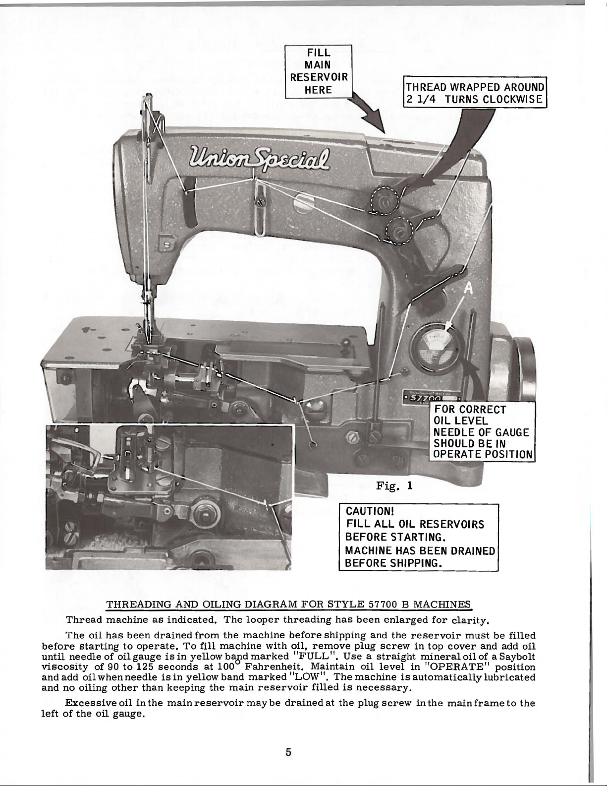
FILL
MAIN
RESERVOIR
HERE
THREAD
2
1/4
WRAPPED
TURNS
CLOCKWISE
AROUND
CAUTION!
FILL
BEFORE
MACHINE
BEFORE
Thread
The
before
until
needle
viscosity
and
add
and
no
Excessive
left
of
the
THREADING
machine
oil
has
starting
of
of
90
oil
when
oiling
oil
been
to
oil
gauge
to
needle
other
oil
gauge.
operate.
125
than
in
as
indicated.
drained
is
seconds
is
keeping
the
main
AND
To
in
in
yellow
OILING
from
fill
machine
yellow
at
100
band
the
reservoir
DIAGRAM
The
looper
the
machine
baBd
Fahrenheit.
marked
main
may
with
marked
reservoir
be
FOR
threading
before
oil,
remove
"FULL".
Maintain
''LOW".
filled
drained
STYLE
has
been
shipping
plug
Use a straight
The
machine
is
necessary.
at
the
plug
5
ALL
57700
and
oil
OIL
RESERVOIRS
STARTING.
HAS
BEEN
SHIPPING.
B MACHINES
enlarged
the
reservoir
screw
level
screw
in
mineral
in
is
automatically
in
DRAINED
for
clarity.
must
top
cover
oil
"OPERATE"
the
main
frame
be
filled
and
add
oil
of a Saybolt
position
lubricated
to
the
Page 6
INSTRUCTIONS
LUBRICATION
FOR
MECHANICS
CAUTION!
reservoir
before
the
beginning
oil
to
Use a straight
Fahrenheit
No.
17
5.
Fill
and
check
band
marked
CAUTION!
It
is
an
extended
and
directly
further
hand
distribute
Oil
may
located
NOTE:
below
Looper
assembling
spot
screw
Oil
has
been
must
the
be
to
various
filled
operate.
parts.
mineral
in
the
main
main
oil
level
reservoir
at
"Full".
It
is
important
recommended
period
oil
oil
be
oiling
to
the
be
the
needle
will
the
various
drained
cloth
avoid
be
is
sure
in
oil
timespot.
drained
to
Full
reservoir.
gauge
Oil
should
that a new
lubricated
be
from
plate
and
feed
holes
the
Run
from
proper
machine
speed
the
operation
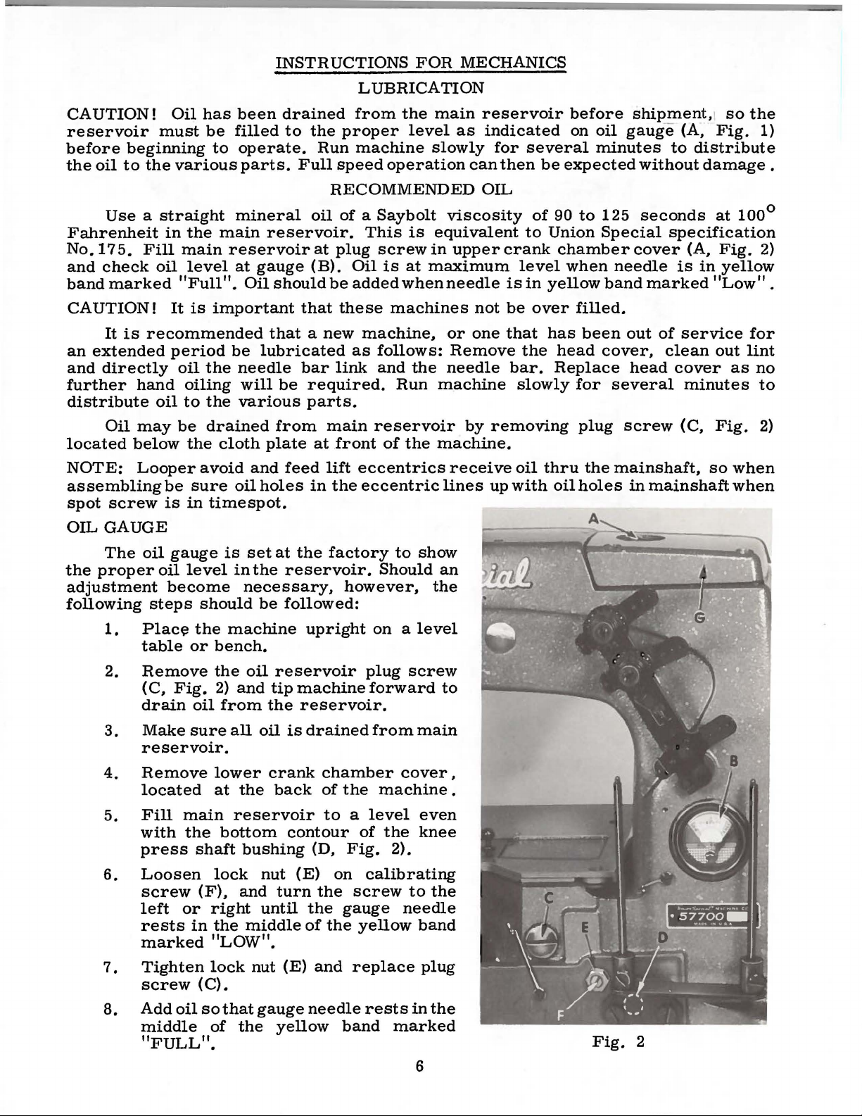
RECOMMENDED
oil
of a Saybolt
This
at
plug
screw
(B).
Oil
is
at
be
added
that
these
as
bar
link
required.
when
machines
machine~
follows:
and
Run
parts.
at
in
main
lift
the
reservoir
front
eccentrics
eccentric
of
the
main
level
slowly
viscosity
is
equivalent
in
upper
maximum
needle
or
Remove
the
needle
machine
machine.
receive
lines
reservoir
as
indicated
can
OIL
not
one
by
for
several
then
be
of
90
to
Union
crank
level
is
in
yellow
be
over
that
has
the
bar.
Replace
slowly
removing
oil
thru
up
with
oil
before
on
oil
minutes
expected
to
125
Special
chamber
when
band
filled.
been
head
for
cover,
several
plug
the
holes
shipment,1 so
gaug
e
(A
to
distribute
without
seconds
specification
cover
needle
(A,
is
marked
out
of
service
clean
head
cover
minutes
screw
(C,
mainshaft,
in
mainshaft
~
Fig.
damage
at
100°
Fig.
in
yellow
"Low".
out
as
Fig.
so
when
when
the
1)
.
2)
for
lint
no
to
2)
OIL
GAUGE
The
the
proper
adjustment
following
1.
2.
3.
4.
located
5.
with
press
6.
left
rests
oil
gauge
oil
level
become
steps
Place
table
should
the
or
Remove
(C,
Fig.
drain
Make
oil
sure
reservoir.
Remove
Fill
main
the
shaft
Loosen
screw
(F),
or
in
marked
is
set
in
the
necessary,
be
machine
bench.
the
oil
2)
and
from
all
oil
lower
at
the
reservoir
bottom
bushing
lock
nut
and
right
the
until
middle
"LOW".
at
the
reservoir.
followed:
upright
reservoir
tip
machine
the
reservoir.
is
drained
crank
back
contour
(D,
(E)
turn
the
the
of
factory
Should
however,
on a level
plug
forward
from
chamber
of
the
machine
to a level
of
the
Fig.
on
2).
calibrating
screw
gauge
the
yellow
to
show
screw
main
cover,
even
knee
to
needle
band
an
the
to
•
the
7.
8.
Tighten
screw
Add
middle
oil
lock
(C).
so
of
that
the
nut
gauge
yellow
(E)
and
needle
band
replace
rests
marked
plug
in
the
"FULL".
6
Fig.
2
Page 7
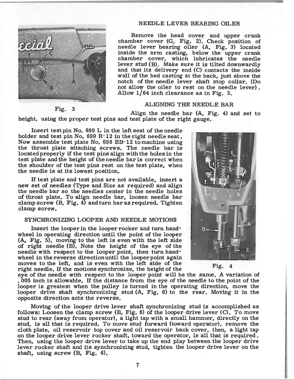
NEEDLE
LEVER
BEARING
OILER
height,
Insert
holder
Now
assemble
the
throat
located
test
plate
the
shoulder
the
needle
Fig.
using
the
test
and
test
plate
properly
and
the
of
is
at
3
proper
pin
No. 699 L
pin
test
attaching
if
the
height
the
its
lowest
test
No. 699
plate
No. 698
test
of
test
pins
pins
in
the
R-12
in
BB-12
screws.
pins
align
the
needle
rest
position.
Remove
chamber
needle
inside
chamber
lever
and
that
wall
of
notch
not
allow
Allow
Align
and
test
left
seat
the
right
to
The
with
bar
on
the
cover
lever
the
arm
cover,
stud
(B).
its
delivery
the
bed
of
the
the
1/64
inch
ALIGNING
the
plate
of
the
needle
machine
needle
the
holes
is
correct
test
plate,
the
(G,
bearing
casting,
Make
casting
needle
oiler
clearance
needle
of
the
needle
seat.
using
bar
in
when
when
head
Fig.
which
sure
end
lever
to
rest
THE
bar
right
is
the
cover
2).
oiler
below
lubricates
it
(C)
at
the
shaft
as
NEEDLE
(A,
gauge.
and
Check
(A,
is
tilted
contacts
back,
on
the
in
Fig.
Fig.
the
stop
needle
Fig.
upper
position
3)
located
upper
the
needle
downwardly
the
inside
just
above
collar.
lever).
3.
BAR
4)
and
set
crank
of
crank
the
(Do
to
If
test
plate
new
set
of
needles
the
needle
of
throat
clamp
clamp
bar
plate.
screw
screw.
(B,
SYNCHRONIZING
Insert
wheel
(A,
Fig.
of
right
needle
wheel
moves
right
eye
• 005
needle.
of
inch
looper
looper
opposite
Moving
follows:
stud
to
stud,
cloth
on
is
plate,
the
Then,
lever
rocker
shaft,
the
in
operating
5),
needle
with
in
the
to
the
the
needle
is
is
greatest
drive
direction
Loosen
rear
all
looper
using
using
moving
respect
reverse
If
allowable.
of
(away
that
oil
drive
the
shaft
screw
and
(Type
so
the
To
Fig.
looper
direction
(B).
left,
the
and
motions
with
when
shaft
acts
the
looper
the
from
is
required.
reservoir
lever
looper
and
(B,
test
pins
are
and
Size
needles
align
4)
and
LOOPER
in
the
center
needle
turn
AND
looper
until
to
the
left
Note
to
direction
the
is
the
looper
until
even
synchronize,
respect
If
the
the
to
distance
pulley
synchronizing
the
reverse.
drive
clamp
screw
operator), a light
To
top
cover
rocker
drive
its
Fig.
lever
synchronizing
6).
not
as
bar,
bar
NEEDLE
rocker
the
is
even
height
point,
the
with
the
is
stud
lever
(B,
move
and
shaft,
to
available,
required)
in
the
loosen
as
required.
and
point
with
of
the
then
looper
the
left
the
looper
from
turned
(A,
shaft
Fig.
6)
tap
stud
oil
toward
take
up
stud,
insert
and
align
needle
needle
holes
bar
Tighten
MOTIONS
turn
hand-
of
the
looper
the
left
side
eye
of
the
turn
hand-
point
side
height
point
the
in
Fig.
again
of
of
will
eye
the
6)
the
the
of
the
operating
to
synchronizing
of
the
looper
with a small
forward
reservoir
the
the
tighten
(toward
back
operator,
end
play
the
a
be
the
needle
the
stud
drive
hammer,
between
looper
Fig.
same.
to
direction,
rear.
Moving
is
accomplished
lever
operator),
cover,
is
then, a light
all
that
the
drive
4
A
variation
the
point
move
(C).
directly
remove
is
required.
looper
lever
it
To
of
the
the
in
the
move
on
the
the
tap
drive
on
the
of
as
7
Page 8
SYNCHRONIZING
LOOPER
AND
NEEDLE
MOTIONS
(Continued)
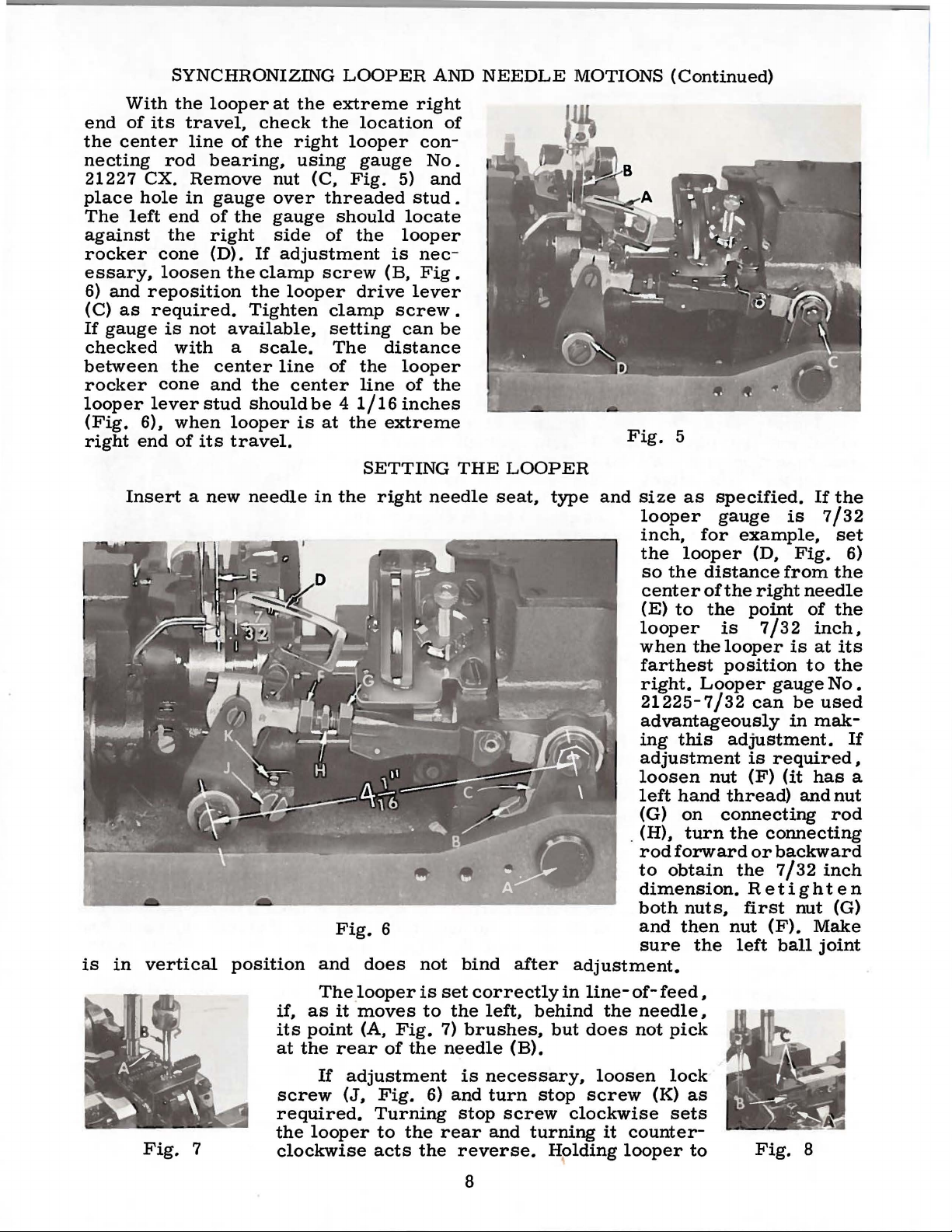
With
end
of
its
the
center
necting
21227 CX.
place
The
against
rocker
essary,
6)
(C)
If
checked
between
rocker
looper
(Fig.
right
is
hole
left
cone
loosen
and
reposition
as
required.
gauge
cone
lever
6),
end
Insert a new
in
vertical
the
travel,
line
rod
Remove
in
end
the
is
not
with
the
when
of
its
looper
check
of
the
bearing,
gauge
of
the
right
(D).
If
the
clamp
the
Tighten
available,
a
scale.
center
and
the
stud
should
looper
travel.
needle
position
at
the
extreme
the
right
using
nut
over
gauge
side
adjustment
looper
line
center
is
looper
(C,
Fig.
threaded
should
of
screw
clamp
setting
The
of
be 4 1/16
at
the
in
the
Fig.
and
right
location
con-
gauge
5)
stud
locate
the
looper
is
nec
(B,
Fig
drive
the
line
SETTING
does
lever
screw.
can
distance
looper
of
inches
extreme
right
6
not
of
No.
and
.
.
be
the
THE
needle
bind
LOOPER
seat,
type
after
Fig.
and
size
looper
inch,
the
so
center
(E)
looper
when
farthest
right.
21225-7/32
advantageously
ing
adjustment
loosen
left
(G)
. (H),
rod
to
dimension.
both
and
sure
adjustment.
5
as
specified.
gauge
for
looper
the
distance
of
to
the
the
Looper
this
nut
hand
on
turn
forward
obtain
nuts,
then
the
is
example,
(D,
Fig.
from
the
right
point
is
looper
position
can
adjustment.
is
(F)
thread)
connecting
the
or
the
Retighten
first
nut
left
needle
7/32
is
gauge
be
in
required
(it
and
connecting
backward
7/32
nut
(F).
ball
If
the
7/32
set
the
of
the
inch,
at
its
to
the
No
used
mak-
has
nut
rod
inch
(G)
Make
joint
6)
•
If
,
a
The
Fig.
7
if,
as
it
its
point
at
the
rear
If
adjustment
screw
required.
the
clockwise
(J,
looper
looper
moves
(A,
is
to
Fig.
of
the
Fig.
Turning
to
acts
6)
the
the
set
correctly
the
7)
brushes,
needle
is
and
stop
rear
reverse.
8
in
left,
necessary,
turn
(B).
screw
and
behind
but
stop
turning
Holding
line-
clockwise
the
does
loosen
screw
it
looper
of-
needle,
not
counter-
feed,
pick
lock
(K)
sets
as
to
Fig.
8
Page 9
the
front
setting
while
is
obtained
making
and
SETTING
this
adjustment
recheck
THE
the
adjustment.
LOOPER
may
prove
(Continued)
helpful.
Tighten
lock
screw
whE'n
The
inch
below
of
the
needle.
up
or
down
alignment
The
slots
in
The
3/64
be
inch
centered
height
the
as
of
the
needles
throat
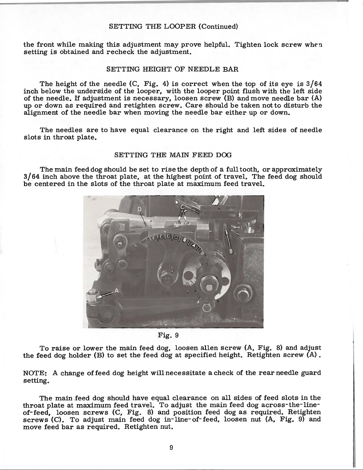
main
above
in
of
the
underside
If
adjustment
required
needle
are
plate.
feed
dog
the
throat
the
slots
SETTING
needle
of
the
is
and
retighten
bar
when
to
have
SETTING
should
plate,
of
the
HEIGHT
(C.
Fig.
looper,
necessary,
moving
equal
clearance
THE
be
set
to
at
the
throat
4)
is
with
screw.
the
MAIN
rise
highest
plate
OF
NEEDLE
correct
the
loosen
Care
needle
on
the
depth
at
maximum
looper
screw
should
the
FEED
point
BAR
when
the
point
(B)
be
bar
either
right
DOG
of a full
of
travel.
feed
top
flush
and
move
taken
up
and
tooth,
The
travel.
of
or
left
its
eye
with
the
left
needle
not
to
disturb
down.
sides
or
approximately
feed
of
dog
is
3/64
side
bar
(A)
the
needle
should
Fig.
9
To
the
feed
NOTE:
raise
dog
A
or
holder
change
lower
(B)
of
feed
the
to
dog
main
set
height
the
feed
feed
dog,
will
loosen
dog
at
specified
necessitate a check
allen
setting.
The
throat
of-feed,
screws
move
feed
main .feed
plate
at
loosen
(C).
bar
To
dog
maximum
screws
adjust
as
required.
should
feed
(C,
main
Retighten
have
travel.
Fig.
feed
equal
8)
dog
clearance
To
adjust
and
position
in-line-of-feed,
nut.
9
the
on
main
feed
screw
height.
of
all
sides
feed
dog
loosen
(A,
Fig.
Retighten
the
rear
of
dog
as
required.
nut
8)
and
adjust
feed
screw
needle
slots
(A) •
guard
in
across-the-line-
Retighten
(A,
Fig.
9)
the
and
Page 10

The
the
throat
throat
should
To
the
feed
differential
plate,
plate
be
parallel
raise
dog
at
or
at
SETTING
feed
at
the
maximum
to
the
lower
the
required
dog
highest
feed
top
the
differential
height.
THE
should
point
travel.
surface
DIFFERENTIAL
also
be
set
to
of
travel
In
addition
of
the
feed
Retighten
and
throat
dog,
screw.
FEED
rise
the
center
to
this
plate
loosen
DOG
depth
the
across-the-line-of-feed.
screw
in
teeth
of a full
the
feed
of
(B,
Fig.
tooth
slots
the
feed
9)
and
above
of
the
dog
set
Loosen
or
backward
ential
with
securely.
NOTE:
through
the
feed
the
throat
bar
top
Turn
its
cycle
plate
set
screws
as
required.
(D)
surface
machine
at
to
and
the
(C,
The
be
rotated,
of
the
by
hand
does
not
forward
Fig.
throat
9)
loosening
so
to
make
contact
end
and
the
plate,
the
of
its
move
of
differential
sure
travel.
the
differential
set
screws
across-the-line-of-feed.
the
differential
main
feed
(C)
feed
dog
dog
at
will
feed
back
feed
also
can
be
dog
end
bar
(D)
allow
aligned
Tighten
has
of
its
forward
the
differ-
parallel
screws
clearance
travel
or
The
selector
ible
through
selector
it
back
This
of 2 to
by
hand,
its
stroke.
differential
slide
the top
slide
decreases
Class
1,
depending
making
SETTING
(B)
to
(B)
toward
the
of
machine
sure
feed
ratio
the
desired
of
the
cloth
the
differential
has a stretching
on
the
length
the
differential
THE
is
front
Fig.
DIFFERENTIAL
set
by
position.
plate
increases
feed.
of
stitch
feed
10
loosening
The
on
the
Retighten
ratio
set
dog
10
screw
left
the
at
clears
FEED
screw
side.
amount
screw.
of
the
the
and
Moving
3/4
main
main
RATIO
(A,
Fig.
selector
of
differential
to 1 up
feed
feed
10)
and
moving
slide
the
to a gathering
dog.
at
are
differential
and
Turn
the
back
the
access-
feed
moving
ratio
machine
end
of
Page 11

(A,
Set
Fig.
the
11)
stitch
(it
has a left
to
the
CHANGING
required
hand
thread)
Turning
turning
the
with
stud
"L"
setting
STITCH
length.
and
screw
it
in a counterclockwise
stitch.
an
"S"
toward
lengthens
the
stitch
This
turning
The
and
the
LENGTH
is
accomplished
(B)
clockwise
head
an
"L",
"S"
shortens
the
stitch.
to
the
the
stitch
of
the
moving
Retighten
required
by
adjusting
shortens
mains
the
the
stitch
length.
loosening
the
direction
haft
(C)
stitch
and
locknut
locknut
screw
stitch
lengthens
is
regulating
toward
marked
(C)
(B).
and
after
the
needle
permissible.
within
left,
needle
NOTE:
feed
back
The
be
needle
left
needle
or
guard
needle
after
(D)
about
is
even
guard
Adjustment
dog
height.
Set
the
toward
looper
set
as
low
until
needle.
guard
backward,
as
required
guard,
guard
Fig.
11
when
It
should
3/64
with
as
required,
SETTING
front
the
path
may
as
possible,
the
point
The
or
right
merely
loosen
is
properly
at
its
inch
the
of
needle
of
brush
of
front
and
screws
most
be
set
of
the
needle.
and
the
rear
FRONT
guard
the
looper
but
not
yet
the
looper
needle
needle
loosen
retighten
set.
NOTE:
corresponding
and a check
so
that
forward
as
low
needle,
To
move
retighten
needle
NEEDLE
so
pick
have
guard
at
any
screws
screws.
(H),
move
Any
SETTING
Set
the
it
point
as
until
needle
that
as
it
at
its
is
just
should
time.
(G,
guard
change
change
of
the
THE
rear
needle
does
possible,
guard
it
moves
the
vertical
To
not
of
the
point
guard
screw.
will
GUARD
pushes
left
past
not
To
move
Fig.
raise,
and
in
in
feed
REAR
quite
travel.
yet
of
necessitate
the
behind
needle.
face
the
left
contact
guard
10)
lower
retighten
stitch
the
dog
height.
guard
contact
A
have
the
merely
left
the
needle
It
push
side
the
forward
move
or
length
rear
NEEDLE
clearance
its
looper
the
screws
needle
(C,
Fig.
the
vertical
loosen
a
needle
should
left
of
the
rear
needle
rotate
(E),
check
.
will
necessitate
guard
GUARD
10)
rear
of
face
moving
screw
setting
horizontally
of
the
right
. 005
Fig.
approach
(F).
of
the
inch
to
move
main
12
the
a
is
NOTE:
setting.
presser
released
located
Retighten
A
The
thread
foot
when
If
adjustment
at
screw.
change
is
the
the
back
in
stitch
tension
raised
presser
is
of
After
length
THREAD
release
to
within
foot
needed,
the
machine
adjustment
WILL
is
set
1/8
has
reached
loosen
there
NOT
TENSION
correctly
inch
and
of
its
tension
move
should
11
require a change
RELEASE
when
the
end
highest
release
tension
be
no
it
begins
of
its
position.
lever
disc
separator
binding
in
front
to
travel
screw
at
any
needle
function
and
is
(A,
Fig.
as
required
point.
guard
as
the
entirely
12),
.
Page 12

The
remove
Also
inch
the
Fig.
opening
is
released
the
below
in
operating
is
in
then,
throat
connection
obtain
screw.
so
that
see
mentioned
the
there
clearance
presser
4)
and
in
throat
the
If
adjustment
the
while
plate
the
Check
needle
if
presser
height
presser
should
bar
the
the
and
plate,
throat
direction
low
position.
holding
surface,
and
1 I
16
in
previous
of
the
between
connection
bottom
bed
when
the
with
plate.
is
presser
guide
inch
setting
bar
is
foot
SETTING
presser
foot
when
be
approximately
lower
surface
the
foot
presser
the
feed
needed,
until
pry
with a screwdriver
setting
by
in
its
can
paragraph.
the
Loosen
foot
up
turning
high
be
bar
the
surface
and
lifter
foot
resting
turn
handwheel
needle
screw
down
presser
and
handwheel
position
removed
HEIGHT
foot
guide
dog
retighten
(D,
of
Fig.
lifter
1 I 16
(E,
head
lever
down
bar
(F)
on
the
bar
and
of
on
to
as
OF
PRESSER
4)
lever
,
is
set
(B,
BAR
correctly
Fig.
12)
Fig.
if
is
13
it
is
fully
possible
depressed.
to
Thread
machine
Fig.
14
as
indicated
THREADING
in
Fig. 1 and
The
rotary
eyelets
the
sufficient
under
off
nut
The
the
thread.
tension
and
right
surface
The
support
should
spring
looper
SETTING
needle
2 1 I 4
set
the
needle
tension
of
looper
tension
be
set
must
thread
EYELET
start
THREAD
thread
left
thread
to
the
thread
disc
just
still
should
THE
NEEDLE
AND
operating
is
times.
needle
tension
produce
fabric.
tension
assembly,
below
have
be
TAKE-UP
on a piece
TENSION
to
be
wrapped
Pull
the
thread
uniform
is
applied
the
end
free
length.
just
sufficient
THREAD
thread
tension
at
2 1 I 2
stitches
and
of
the
The
FRAME
WIRE
of
fabric.
around
through
at 2 ounces;
ounces
on
at
the
the
adjusting
tension
tension
to
steady
the
the
the
castpost
the
or
•
on
Set
the
mounting
Top
of
take-up
when
loop,
needle
reverse
needlethread
screw
bar
for
(B).
wire
is
more
(C)
at
frame
Lower
to
the
bottom
loop.
be
for
even
eyelet
more
with
of
its
hole
needle
top
stroke.
12
(A,
of
Fig.
thread
holes
Lower
13)
in
in
314
the
the
this
inch
stitch,
needle
setting
abovethe
raise
thread
for
less
center
for
less
eyelet
needle
of
•
(D)
Page 13

The
looper
consequently,
when
of
plate
pulled
slots
assembly
cast-
as
the
the
left
assembly
causes
off
the
looper
off
plate
looper
needle
by
to
thread
can
be
thread
is
(B)
the
take-up.
more
the
reaches
thread
bottom
assembly
SETTING
take-up
set
to
is
clearly
is
adjustable,
Moving
to
of
is
its
extreme
LOOPER
(A,
compensate
just
cast
visible
the
be
pulled
the
screw
set
correctly
Fig.
for
off
the
below
and
its
cast-off
from
slots
position
'I'HREAD
14)
is
not
varying
highest
the
underside
setting
plate
the
cones,
causes
when
to
the
the
TAKE-
spotted
conditions.
lobe
of
the
of
determines
assembly
and
less
looper
left.
UP
on
the
take-up
the
looper.
the
to
the
moving
thread
thread
main
It
is
when
amount
top
the
to
be
just
shaft
set
correctly
the
The
cast-off
of
of
the
cast-off
pulled.
becomes
and,
point
thread
screw
plate
The
taut
Regulate
enough
is
placed
wise
acts
the
pressure
on
the
the
reverse.
presser
on
the
fabric.
PRESSER
spring
presser
Turning
FOOT
regulating
foot
to
it
clockwise
feed
PRESSURE
screw
the
increases
(E,
work
Fig.
13)
uniformly
the
pressure,
so
that
it
exerts
when a slight
counterclock-
only
tension
13
Page 14

9
'
',,
',
',
I
---·~
I
I
.
I
I
I
I
'
I
I
'
26
14
Page 15

THROAT
PLATE,
FOLDER,
AND
MISCELLANEOUS
FOLDER
SUPPORT,
COVERS
STRIP
TENSION
Ref.
No.
1
2
3
4
5
6
7
8
9
10
11
12
13
14
15
16
17
18"
19
20
21
22
23
24
25
26
27
28
29
30
31
32
33
34
35
36
37
38
Part
No.
22839
660-313
87
90
25
25
T38
90
20
188
A-12
c
E
c
D
s
cc
v
K
J
R-5/8
D
D
E
57724
22526
57801 A
22839
22839
57802 A
22526
57764 A
23432
52864 N
23425
57764 B
22564
57885 A
43281
57880
51280
57882 G
22848
57882 c
22848
57885
23406
22848
57864
22548
23439
23439
Description
Screw,
Well
Screw,
Throat
Screw,
Cloth
Screw,
Screw,
Cloth
Screw----------------------------------------------
Screw,
Folder
Screw---------------------------------------------Screw----------------------------------------------
Folder
Folder
Screw----------------------------------------------
Washer
Folder
Screw----------------------------------------------
Hinge
Hinge
Screw---------------------------------------------Throat
Front
Washer,
Screw,
Support
Screw---------------------------------------------Swinging
Folder
Screw----------------------------------------------
Clamp
Screw----------------------------------------------
Strip
for
throat
Nut
-------------------------------------------
for
throat
Plate----------------------------------------
for
cloth
Plate
Plate
Pin
Bracket
Dowel
Cloth
Tension---------------------------------------
Screw-----------------------------------------Adjustable
-----------------------------------------
for
cloth
for
cloth
Sliding
for
cloth
Support
Clamp--------------------------------------Support
Plate
Support
------------------------------------------
Plate
for
Post----------------------------------------
---------------------------------------------
Plate,
Support
Pin
Guard-----------------------------------
for
front
front
Cover
plate
plate
plate
plate
plate
plate
Platform
Bracket
--------------------------------------Hinged
Spring
------------------------------------cloth
cloth
Hinge--------------------------------
for
folder
Pin
support
------------------------------
-------------------------------
-------------------------------
-------------------------------
Cover
----------------------------------
----------------------------
-------------------------------
-----------------------------
------------------------------
Bracket
--------------------------------
--------------------------------
guard
guard--------------------------
support
-----------------------
-----------------------
------------------------
bracket
---------------
Amt.
Req.
2
2
2
1
2
1
1
2
1
2
1
1
1
2
1
1
2
1
1
1
1
1
2
1
2
1
1
1
1
2
1
1
2
1
2
1
2
2
15
Page 16
16
Page 17
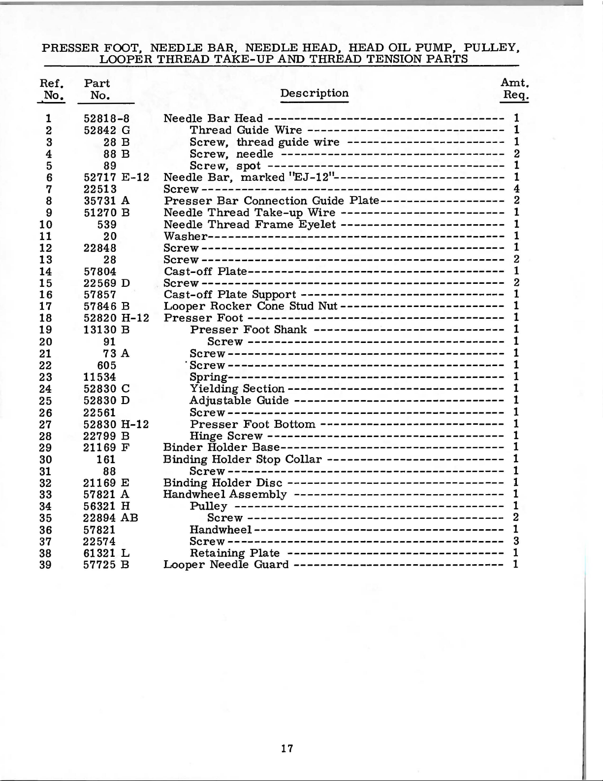
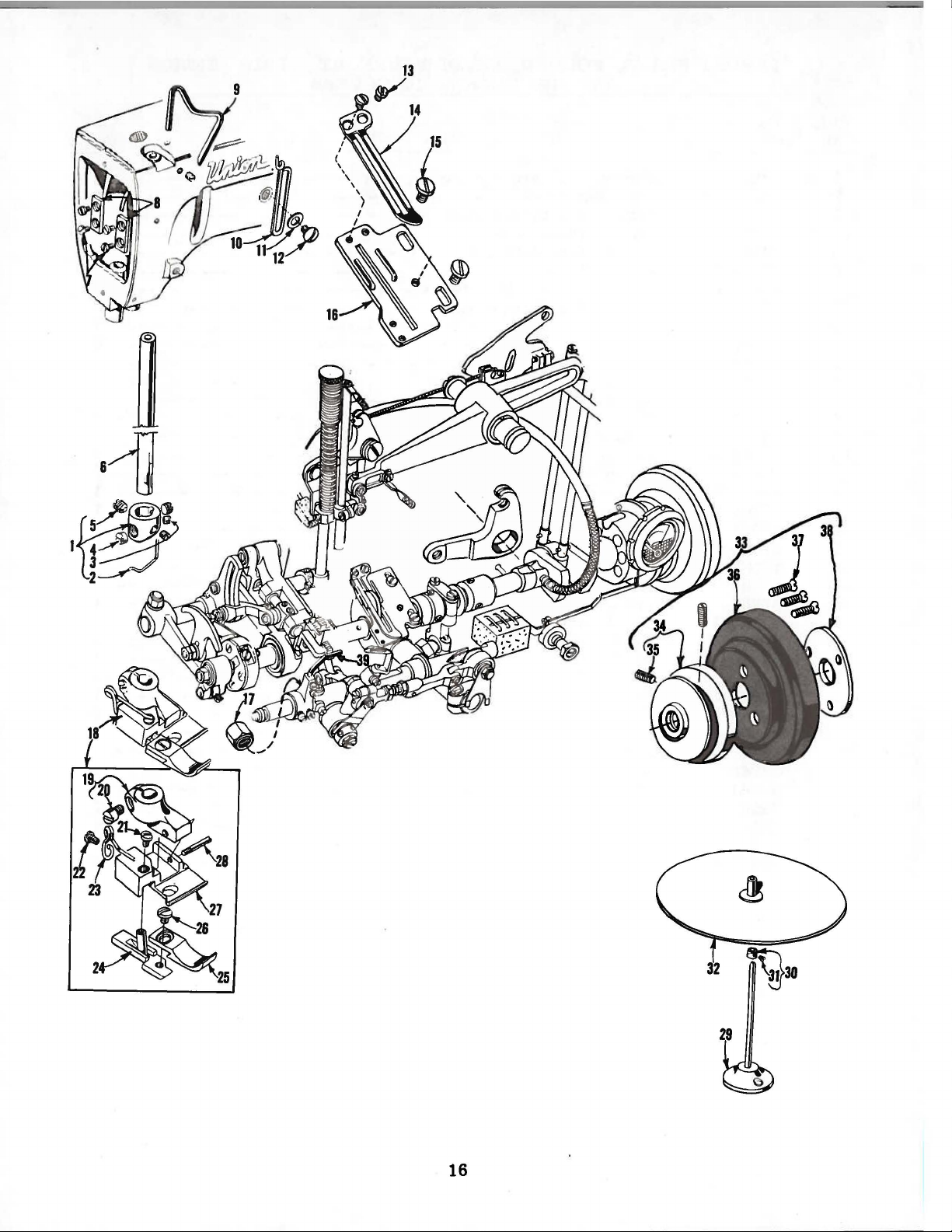
PRESSER
FOOT,
LOOPER
NEEDLE
THREAD
BAR,
TAKE-UP
NEEDLE
AND
HEAD,
THREAD
HEAD
TENSION
OIL
PUMP,
PARTS
PULLEY,
Ref.
No.
_._
1
2
3
4
5
6
7
8
9
10
11
12
13
14
15
16
17
18
19
20
21
22
23
24
25
26
27
28
29
30
31
32
33
34
35
36
37
38
39
Part
No.
52818-8
52842
52717
22513
35731 A
51270
22848
57804
22569
57857
57846
52820
13130
11534
52830
52830
22561
52830
22799
21169
21169
57821 A
56321 H
22894
57821
22574
61321 L
57725
28 B
88
89
539
20
28
91
73
605
161
88
G
B
E-12
B
D
B
H-12
B
A
c
D
H-12
B
F
E
AB
B
Description
Needle
Needle
Screw----------------------------------------------
Presser
Needle
Needle
Washer--------------------------------------------Screw---------------------------------------------Screw----------------------------------------------
Cast-off
Screw----------------------------------------------
Cast-off
Looper
Presser
Binder
Binding
Binding
Handwheel
Looper
Bar
Head
Thread
Screw,
Screw,
Screw,
Bar,
Thread
Thread
Presser
Screw
Screw------------------------------------------
·Screw-----------------------------------------Spring-----------------------------------------Yielding
Adjustable
Screw------------------------------------------
Presser
Hinge
Holder
Screw------------------------------------------
Pulley
Screw--------------------------------------Handwheel-------------------------------------Screw-----------------------------------------Retaining
Guide
thread
needle
spot
Bar
Plate---------------------------------------
Plate
Rocker
Foot
Screw
Holder
Holder
Assembly
-----------------------------------------
Needle
-----------------------------------Wire
------------------------------------
marked
Connection
Take-up
Frame
Support
Cone
---------------------------------------
Foot
Section---------------------------------
Foot
Shank
---------------------------------------
Guide
Bottom
------------------------------------
Base----------------------------------
Stop
Disc
Plate
Guard
------------------------------
guide
----------------------------------
wire
''EJ-12"--------------------------
Guide
Wire
Eyelet
-------------------------------
Stud
-----------------------------
--------------------------------
Collar
---------------------------------
--------------------------------
---------------------------------
--------------------------------
------------------------
Plate-------------------
-------------------------
-------------------------
Nut-------------------------
----------------------------
---------------------------
Amt.
Req.
1
1
1
2
1
1
4
2
1
1
1
1
2
1
2
1
1
1
1
1
1
1
1
1
1
1
1
1
1
1
1
1
1
1
2
1
3
1
1
17
Page 18

18
Page 19
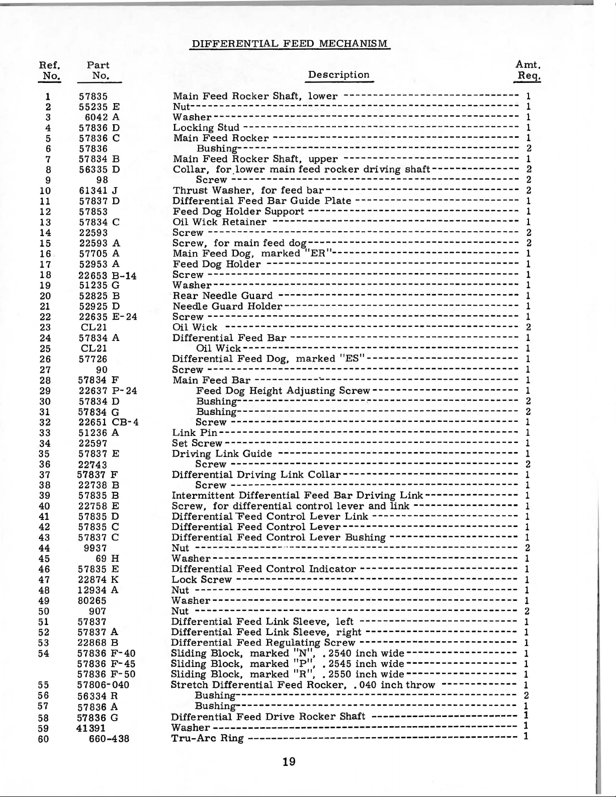
DIFFERENTIAL
FEED
MECHANISM
Ref.
No.
1
2
3
4
5
6
7
8
9
10
11
12
13
14
15
16
17
18
19 51235 G
20
21
22
23
24
25
26 57726
27
28
29
30
31
32
33
34
35
36
37
38
39
40
41
42
43
44
45
46
47
48
49
50
51
52
53
54
55
56
57
58
59
60
Part
No.
57835
55235
6042 A
57836
57836
57836
57834
56335
98
61341 J
57837
57853
57834
22593
22593 A
57705 A
52953 A
22653
52825
52925 D
22635
CL21
57834
CL21
90
57834 F
22637
57834
57834
22651
51236
22597
57837
22743
57837
22738
57835
22758
57835
57835
57837
9937
69 H
57835
22874 K
12934
80265
907
57837
57837
22868
57836
57836
57836
57806-040
56334
57836
57836
41391
660-438
E
D
c
B
D
D
c
B-14
B
E-24
A
P-
24
D
G
CB-4
A
E
F
B
B
E
D
c
c
E
A
A
B
F-40
F-45
F-50
R
A
G
Description
Main
Feed
Nut-------------------------------------------------------VVasher---------------------------------------------------Locking
Main
Bushing------------------------------------------------
Main
Collar,
Screw------------------------------------------------Thrust
Differential
Feed
Oil
VVick
Screw
Screw,
Main
Feed
Screw
VVasher----------------------------------------------------
Rear
Needle
Screw----------------------------------------------------Oil
VVick
Differential
Oil
Differential
Screw-----------------------------------------------------
Main
Feed
Bushing----------------------~-------------------------
Bushing------------------------------------------------
Screw
Link
Pin---------------------------------------------------
Set
Screw--------------------------------------------------
Driving
Screw-------------------------------------------------
Differential
Screw
Intermittent
Screw,
Differential-Feed
Differential
Differential
Nut
---------------
VVasher---------------------------------------------------Differential
Lock
Screw
Nut
-------------------------------------------------------
VVasher---------------------------------------------------Nut
-------------------------------------------------------
Differential
Differential
Differential
Sliding
Sliding
Sliding
Stretch
Bushing------------------------------------------------
Bushing------------------------------------------------
Differential
VVasher----------------------------------------------------
Tru-Arc
Rocker
Stud-----------------------------------------------
Feed
Rocker------------------------------------------
Feed
Rocker
for_lower
VVasher,
Feed
Dog
Holder
Retainer
----------------------------------------------------for
main
Feed
Dog,
Dog
Holder-------------------------------------------
-----------------------------------------------------
Needle
Feed
Block,
Block,
Block,
Guard
Guard
-------------------------------------------------Feed
VVick
-----------------------------------------------
Feed
Bar
Dog
-------------------------------------------------
Link
Guide
Driving
------------------------------------------------Differential
for
differential
Feed
Feed
Feed
------------------------------------------------
Feed
Feed
Feed
Differential
Feed
Ring
Shaft,
Shaft,
main
for
Bar
Support------------------------------------
------------------------------------------
feed
marked
Holder----------------------------------------
Bar
Dog,
-------
Height
Control
Control
Control
Control
Link
Link
Regulating
marked
marked
marked
Feed
Drive
----------------------------------------------
lower
upper
feed
feed
bar---------------------------------
Guide
dog------------------------------------
"ER"--------------------------------
-----------------------------------------
--------------------------------------marked
----·----
Adjusting
----------------------------------------Link
Collar------------------------------
Feed
control
Lever
Lever------------------------------
Lever
·
·--------------------------------------Indicator---------------------------
Sleeve,
Sleeve,
"N",
"P",
"R",
Rocker, . 040
Rocker
------------------------------
------------------------------
rocker
Plate----------------------------
Screw--------------------------. 2540
. 2545
. 2550
driving
"ES"--------------------------
------------------------------
Screw-------------------------
Bar
Driving
lever
left
right--------------------------
and
Link------------------------Bushing----------------------
---------------------------
inch
inch
inch
Shaft
-------------------------
shaft---------------
Link----------------
link------------------
wide------------------wide------------------wide------------------inch
throw
-------------
Amt.
Req.
1
1
1
1
1
2
1
2
2
2
1
1
1
2
2
1
1
1
1
1
1
1
2
1
1
1
1
1
1
2
2
1
1
1
1
2
1
1
1
1
1
1
1
2
1
1
1
1
1
2
1
1
1
1
1
1
1
2
1
1
1
1
19
Page 20
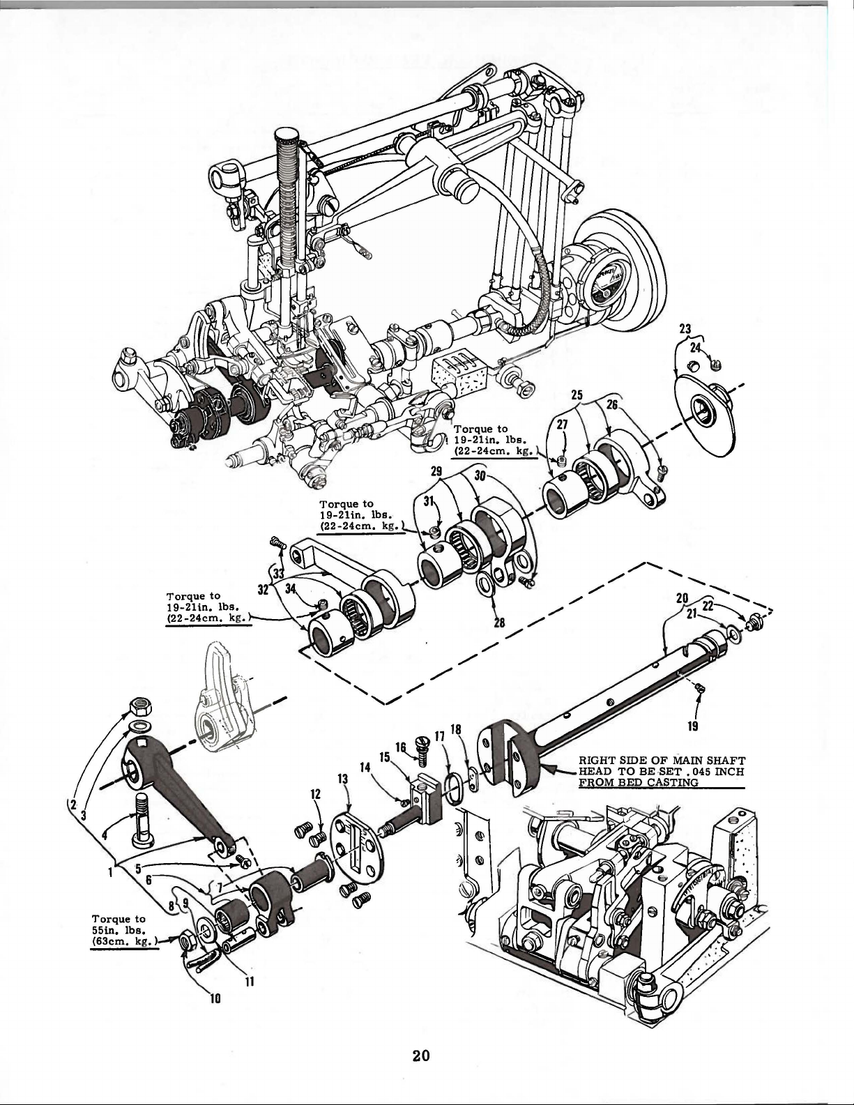
Torque
19-21
(22
-24cm.
in.
to
lbs.
kg .
20
Page 21
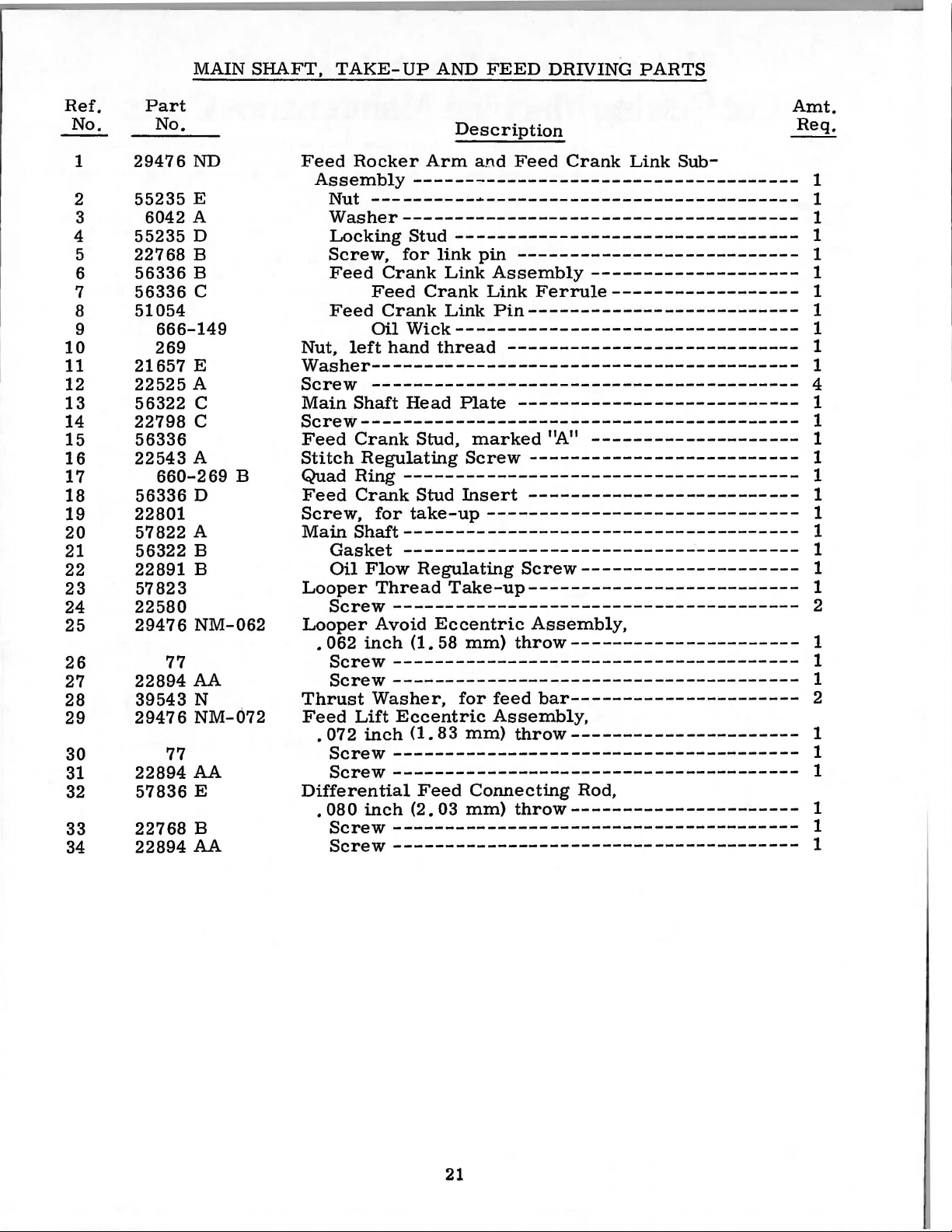
MAIN
SHAFT,
TAKE-UP
AND
FEED
DRIVING
PARTS
Ref.
No.
1
2
3
4
5
6
7
8
9
10
11
12
13
14
15
16
17
18
19
20
21
22
23
24
25
26
27
28
29
30
31
32
33
34
Part
No.
29476
55235
6042 A
55235
22768
56336
56336
51054
21657
22525
56322
22798
56336
22543
56336
22801
57822
56322
22891
57823
22580
2947 6 NM-062
22894
39543
29476
22894
57836
22768
22894
ND
E
D
B
B
c
666-149
269
E
A
c
c
A
660-269
D
A
B
B
77
AA
N
NM-072
77
AA
E
B
AA
B
Description
Feed
Nut,
VVasher-----------------------------------------
Screw
Main
Screw-----------------------------------------Feed
Stitch
Quad
Feed
Screw,
Main
Looper
Looper
Thrust
Feed
Differential
Rocker
Assembly
Nut
----------~------------------------------
VVasher-------------------------------------Locking
Screw,
Feed
Feed
Feed
Oil
left
-----------------------------------------
Shaft
Crank
Regulating
Ring
Crank
for
Shaft--------------------------------------
Gasket
Oil
Flow
Thread
Screw
Avoid
• 062
.
•
inch
Screw
Screw
VVasher,
Lift
072
inch
Screw
Screw
080
inch
Screw
Screw---------------------------------------
Arm
-------------------------------------
Stud
for
Crank
Crank
Crank
VVick
hand
Head
Stud
-------------------------------------Stud
take-up
--------------------------------------
Regulating
---------------------------------------
(1.
---------------------------------------
--------------------------------------Eccentric
(1.
---------------------------------------
---------------------------------------
Feed
(2.
---------------------------------------
a!'\d
Feed
---------------------------------
link
pin
---------------------------
Link
Link
thread
Eccentric
58
83
03
Assembly
Link
Pin--------------------------
---------------------------------
----------------------------
Plate
'
Screw
Insert
Take-up--------------------------
mm)
for
mm)
Connecting
mm)
---------------------------
marked
------------------------------
throw----------------------
feed
Assembly,
throw----------------------
throw----------------------
Crank
--------------------
Ferrule------------------
'~"
--------------------
--------------------------
--------------------------
Screw---------------------
Assembly,
bar----------------------
Rod,
Link
Sub-
Amt.
Req.
1
1
1
1
1
1
1
1
1
1
1
4
1
1
1
1
1
1
1
1
1
1
1
2
1
1
1
2
1
1
1
1
1
1
21
Page 22
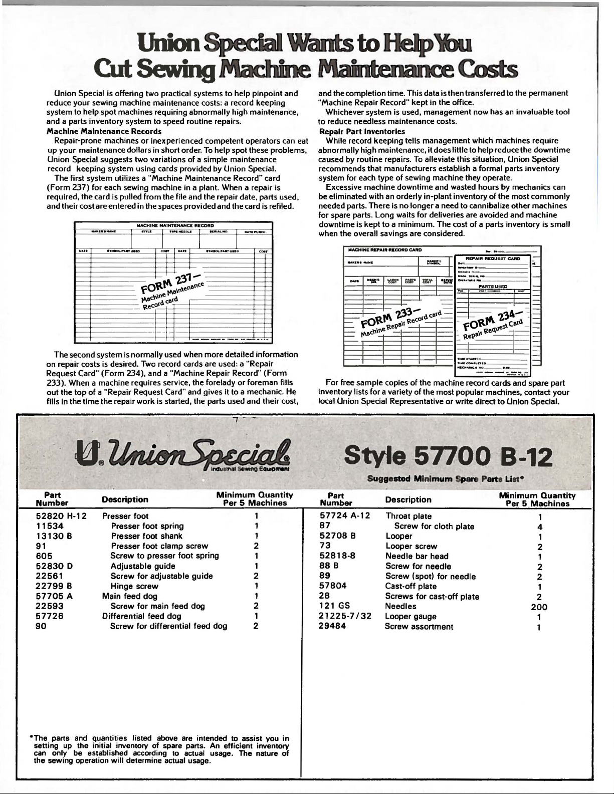
Union Special is offering two practical systems
reduce your sewing machine maintenance cost
system to help spot machines requiring abnormally high maintenanc
and a parts inventory system to speed routine repairs.
Machine Maintenance Records
Repair-prone machines
up your maintenance dollars in short order.
Union Special s•Jggests two variations
record keeping system using cards provided by Union Special.
The first system
(Form
237) for each sewing machine in a plant. When a repair is
required, the card is pulled
and their cost are entered in the spaces provided and the card
.......
-
DATI"
.,....._~ln'U.I
or
inexperienced competent operators can
of
utilizes a "Machine Maintenance Record'' card
from
the file and the repair date, parts used,
MACHIN&
MAIN"RNAHCC ... COfiiO
~
......
....
I
J J
.
O
fOttt'\
1'\Dc"\';;' ce!d
~ec:OI
...
-
2'31-
~el\el\ce
1'\D\1\
--
The second system is normally used when more detailed information
on repair costs
Request Card"
233). When a machine requires service, the forelady
out
the top
fills in the time the repair
is
desired. Two record cards are used: a "Repair
(Form
234), and a "Machine Repair Record"
of
a "Repair Request Card'' and gives
work
is started, the parts used and their cost,
to
help pinpoint and
s:
a record keeping
To
help spot these problems,
a simple maintenance
is
refiled.
...
, .
..,
--
-·
.,.,....._, • .,.u••
-
--
it
_ .
I
•
-·
.....
·-
(Form
or
foreman fills
to a mechanic. He
and the completion time. This data
"Machine Repair Record" kept
e,
Whichever system is used, management now has
to reduce needless maintenance costs.
Repair
Part
While record keeping tells management which machines require
eat
abnormally high maintenance,
caused by routine repairs.
recommends that manufacturers establish a formal parts inventory
system for each type
Excessive machine downtime and wasted hours by mechanics can
be eliminated with
needed parts. There is
for spare parts. Long waits for deliveries are avoided and machine
downtime is kept
when the overall savings are considered .
Inventories
~INit
REPAIR RltCORD CARD
of
sewing machine they operate.
an
orderly in-plant inventory
no
longer a need to cannibalize other machines
to a minimum
-··-·
..
"'1111
.'
mil"
'llr:l"
1'\
=
fOlt
=
1'\0c"\1\e
-
For free sample copies
inventory lists for a variety
local Union Special Representative
1.'3'3- d catd
~e~\1
~eeo'
of
is
then transferred to the permanent
in
the office.
it
does little
To
alleviate this situation, Union Special
. The cost
L'::&IJ..'
-I
-
..:::=
the machine record cards and spare part
of
the most popular machines, contact
to
of
RPAIR
h•
I
-·-·
I
--·
-
..
..
"im'
"""_
o..·-·-·-
-
, _
__ -z'3A-
- fOttt'\ t
.
~
e9a\l
,
....
..
....,.
TJMII-PLPU
M&CMA·III;· NO--·-·--
-
or
write direct
help reduce the
of
the most
a parts inventory is small
-
..
ftiEQU
UT
~ART8 UIE
-·-
~e~\les
-----
to
an
invaluable tool
downtime
commonly
-
CAftD
~
-_
D
-
-·
:
=
catd
-
=
=
-
I
-
-
-
Union Special.
your
Part
Number
52820
11534
13130
91
605
52830
22561
22799
57705
22593
57726
90
*The parts
setting up the initial inventory of spare parts. An efficient inventory
can
the sewing operation
H-12
8
D
8
A
only be established according to actual usage. The nature
and
Description
Presser
Presser
Presser
Presser
Screw
Adjustable
Screw
Hinge
Main
Screw
Differential
Screw
quanttto
es
will
foot
foot
spring
foot
shank
foot
clamp
to
presser
for
screw
feed
dog
for
feed
for
listed above
determine actual usage.
foot
guide
adjustable
main feed dog
dog
differential
are
Minimum
Per 5 Machines
screw
spring
guide
feed dog
intended to assist you in
Quantity
1
1
1
2
1
1
2
1
1
2
1
2
of
Style
Part
Number
57724
87
52708
73
52818-8
88
89
57804
28
121
21225-7/32
29484
A-12
8
B
GS
Su
gge
sted Mini
Description
Throat
Screw
Looper
Looper
Needle bar head
Screw
Screw
Cast-off plate
Screws for
Needles
Looper gauge
Screw
57700
mum
Spar.
P
plate
for
cloth
plate
screw
for
needle
(spot)
for
needle
cast-off
assortment
plate
B-12
arts
Li
st•
Minimum
Per 5 Machines
Quantity
1
4
1
2
1
2
2
1
2
200
1
1
Page 23
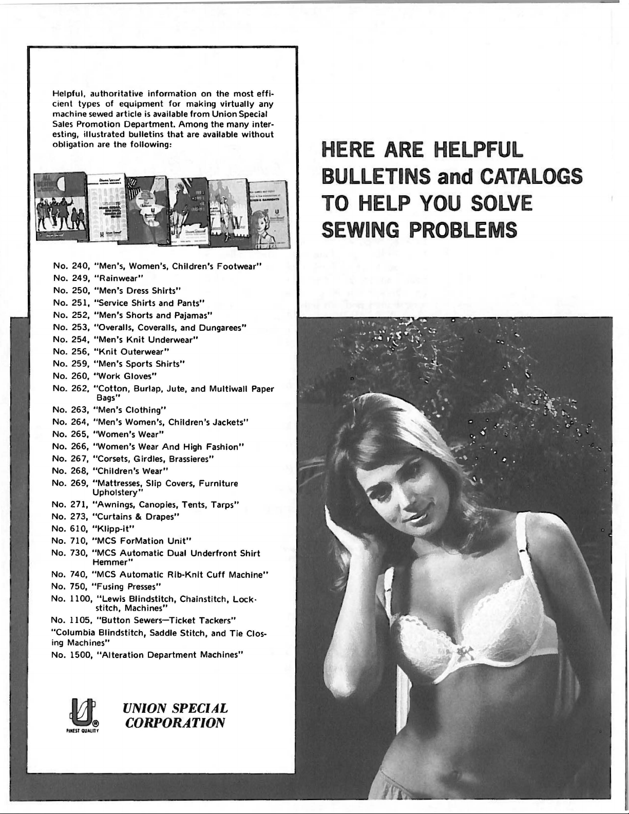
Helpful,
cient
machine sewed
Sales
esting,
obligation
authoritative
types
of
Promotion
illustrated
are
information
equipment
article
is available
Department.
bulletins
the
following
for
making
from
Among
that
are available
:
on
the
virtually
Union
the
many
most
Special
without
effi-
any
inter-
HERE
ARE
HELPFUL
No. 240,
No.
No.
No.
No.
No.
No.
No.
No.
No.
No.
No.
No.
No. 265,
No.
No.
No.
No.
No.
No.
No.
No.
No.
No.
No.
No.
No.
"Columbia
ing Machines"
No.
"Men's,
249,
"Rainwear"
250,
"Men's
251,
"Service
252,
"Men's
253,
"Overalls,
254,
"Men's
256,
"Knit
259,
"Men's
260,
"Work
262,
"Cotton,
Bags"
263,
"Men's
264,
"Men's
"Women's
266,
"Women's
267,
"Corsets, Girdles, Brassieres"
268,
"Children's
269, "Mattresses,
Upholstery"
271,
"Awnings,
273,
"Curtains & Drapes"
610,
"Kiipp-it"
710,
"MCS
730,
"MCS
Hemmer"
740,
"MCS
750,
"Fusing
1100,
"Lewis
stitch,
1105,
"Button
Blindstitch,
1500,
"Alteration
Women's,
Dress
Shirts
Shorts
Coveralls, and Dungarees"
Knit
Outerwear"
Sports
Gloves"
Burlap, Jute,
Clothing"
Women's,
Wear"
Wear
Canopies, Tents,
ForMation Uni
Automatic
Automatic
Presses"
Blindstitch,
Machines"
Sewers-Ticket
Children's
Shirts"
and
Pants"
and Pajamas"
Underwear"
Shirts"
Children's
And
Wear"
Slip
Covers,
Dual
Rib-Knit
Chalnstitch,
Saddle
Stitch,
Department
and
High
Furniture
t"
Underfront
Tackers"
Machines"
Footwear"
Multiwall
Jackets"
Fashion"
Tarps"
Cuff
Machine"
Lock·
and
Tie
Paper
Shirt
Clos-
BULLETINS
TO
SEWING
HELP
PROBLEMS
YOU
and
CATALOGS
SOLVE
UNION SPECIAL
H
NIST QUAl
RY
CORPORATION
Page 24
WORLD'S
FINEST
,
QUALITY
*
-.'
..
INDUSTRIAL
SEWING
MACHINES
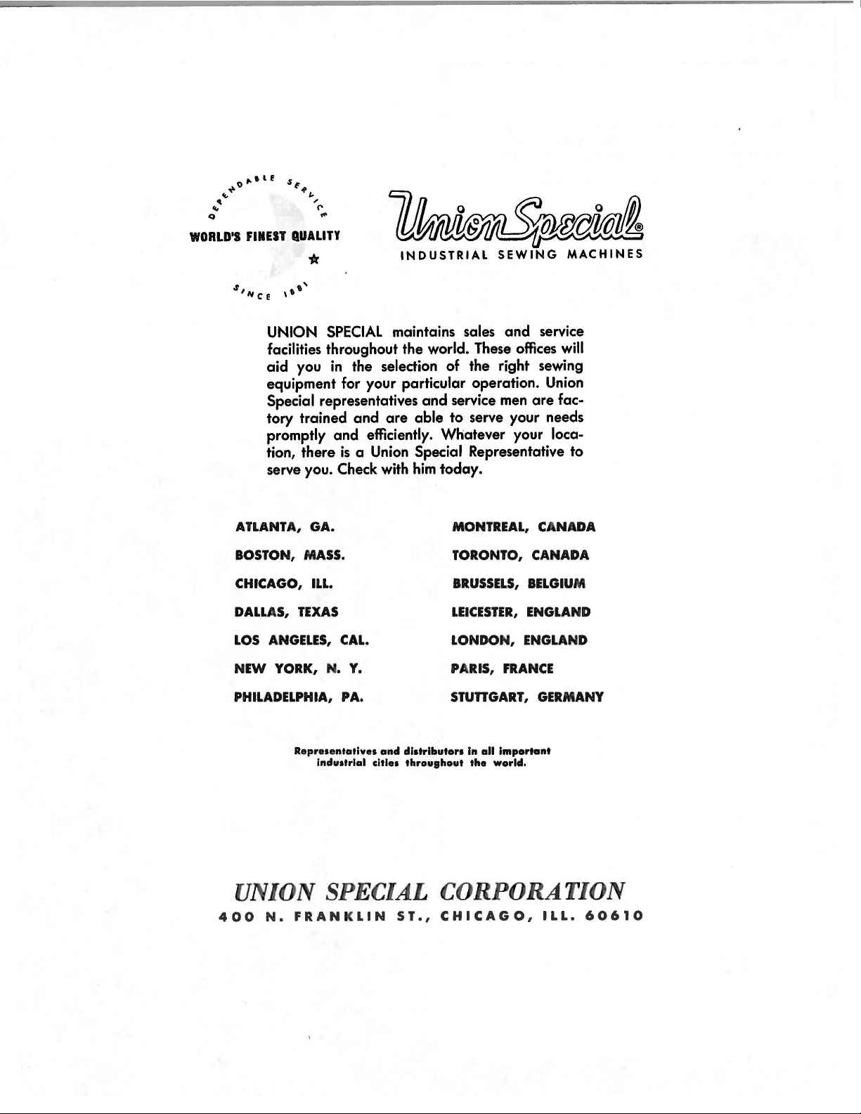
UNION
SPECIAL
maintains sales
and
facilities throughout the world. These offices
aid
you
in
the selection of the right sewing
equipment for your particular operation. Union
Special representatives
tory trained
promptly
tion, there
serve you.
ATLANTA,
BOSTON, MASS. TORONTO,
CHICAGO,
DALL
AS,
LOS
NEW
PHILADELPHIA,
GA.
TEXAS
ANGELES,
YORK, N.
and
and
efficiently. Whatever your loca-
is
a Union Special Representative to
Check with
ILL.
CAL.
Y.
PA. STUnGART,
are
and
service men
able
to
serve your needs
him
today.
MONTREAL, CANADA
BRUSSELS,
LEICESTER,
LONDON,
PA
RIS,
FRANCE
service
will
are
fac-
CANADA
BELGIU
ENGLA
ENGLA
GERMANY
M
ND
ND
Representatives
Industrial cities
UNION SPECIAL
400
N.
FRANKLIN
and
distributors
throughout
ST.,
In
all
Important
the
world.
CORPORATION
CHICAGO,
ILL.
60610
 Loading...