

Page 1
F
INEST
ST
57
®
QUALITY
YLES
100 c
INDUSTRIAL
SEWING
I
MACHINES
CLASS
57100
CATALOG
No.
T141
M
ADVANCED
FIFTY
FLAT
THOUSAND
BED
HIGH
MACHINES
UNION SPECIAL
CHICAGO
Price
$1.00
SPEED
SERIES
CORPORATION
Page 2
C a t a 1 o g N
( S U P P L E M E N T T 0 C A T A L 0 G N
o.
T 1 4 1 M
I N S T R U C T I 0 N S
F 0 R
A D J U S T I N G A N D 0 P E R A T I N G
L I
S T 0 F P A R T S
F 0 R
S t y 1 e
5 7 1 0 0 c
0.
1 3 1 M )
U n i o n
R i g h t s R e
UNION SPECIAL
INDUSTRIAL
F i r s t E d i t i o n
~
1 9 7 7
b y
S p e c i a 1 C o r p o r a t i o n
s e r v e d i n A 1 1 C o u n t r i e s
CORPORATION
SEWING
CHICAGO
MACHINES
P r i n t e d i n
2
U.
S.
A.
April,
1977
Page 3
IDENTIFICATION
OF
MACHINES
Each
t he m
achi
numb
ers have
Exam
ple
minor
Style
Styl
wh
ich differs from the
5 7100
".
T
used in
not
used
cl
ari
parts.
part
number,
part
or
base
ence
number
This
herein.
in
these
are
given
direction
UNION
ne .
one
: "
Style
cha
nges are made
number.
es
of machi n
his.catalo
conjunction
on
Style
ty,
certain
Opposite
description
is
indicated
part.
in
catalog
It
can
classes.
from
of
handwheel
SPECIAL
Style
57100 C
Example:
g
Always
the
also
the
machine
numbers
or
more
letters
".
are
Special
in a standard
"Styl
e 57100 CZ".
es
similar
style
number,
is a supplement
therewith.
57700 N are
57700 N
the
parts
i l
lustration
and amount
by
indenting
use
the
first
applies
References
column when
specifically
be
applied
to
operator's
is
toward
is
identified
classified
suffixed, but
Style
ma
chi ne , a "Z"
in constructi
in
APPLICATION
to
Catalo
Only
those parts
illustrated
ar
e shown
pages,
required.
its
description
part
number
ordering
to
with
discretion
direction,
position
the
while
operator.
as
number s
on are
that
it contains
OF
g No.
and
in
phantom
parts
in
the
the
such
seated
by a
Style
standard
numb
and sp
never contain
contai
n t he l
is
suffixed
grouped
no
CATALOG
131M.
which
list
ed
are
identified
Any
part
under
second
repair
Standard
to
some
as
right,
are
at
to
the
parts.
at
Second
the
assist
that
description
column,
Style
Special
the
er on a name pl
ecial
t he let
ette
.
r "Z
to
ter "Z".
the
under a class
letters.
Edition,
used
on
Style
back
of
this
in
locating
by a
reference
is a component
never
of
machine
Styles
left,
front,
machine.
Operating
Sta
ndar d
".
\.Jh
en on
standard
numb
Exampl e :
and
57100
book.
th
of
of
the
use
the
as
listed
of
machines
back,
ate
on
Styl
ly
er
''Cla
ss
should
be
C, bu t
For
e 57100 C
number,
another
assembly
refer-
etc.,
Advanced High
Throw,
Driving
Filtered
for
Double
Knee
Work
57100
Needle
Mechanism,
Feed
Disc
Press
Space
C
cord.
gauge.
Oil
Bar
Take-up,
for
to
For
Needle
Standard
Return
and
cording
402-0S-1.
Each
UNION
number
The
size
denotes
number,
blade, measured
and
the
eye.
Collectively,
symbol,
which
Special.
Speed,
Bearing
Single
Feed
Presser
Right
spacing
Type 108
SPECIAL
the
kind
stamped
in
thousandths
is
given
Two
needle,
Needle
Reservoir
Pumps
for
Rocker
Large
Foot
of
~eedle
operations
height
GHS
needle
of
on
on
the
STYLE
One
Bar
Drive,
Head
and
Shafts,
Handwheel
Lifter,
Bar 8 1/4
on
light
or
g
~uge
of
tucking
needle.
has
both a type
shank,
the
the
point,
needle
of
an
type
label
OF
Looper,
Light
Enclosed
Base,
Greased
and
Improved
Equipped
Inches
weight
is
.080
1/8
Maximum
NEEDLES
length,
shank,
inch
or
number
of
all
MACHINE
Plain
Weight
Positive
Needle
and
Sealed.
Belt
with
Disc
(209.6
woven
inch
(2.03
inch
(3.18
recommended
number
groove,
denotes
millimeters,
and
size
needles
Feed
Flat
Presser
Automatic
Bearings
Guard.
Thread
mm).
and
mm)
mm). Seam
speed
and a size
finish
the
number
packaged
Bed
Bar
Lubricating
and
Laterial
Prepared
Tensions,
knitted
or
approximately
6500
and
largest
midway
represents
and
sold
Machines,
and
Needle
Bronze
Looper
Bearings
Travel,
for
Maximum
fabrics,
specification
R.P.M.
number.
other
The
details.
diameter
between
the
by
the
complete
Union
Medium
Bar
System,
use
with
without
No.
5
type
of
the
shank
3
Page 4
The
round
e
needle,
complete
d,
chromium
To
point,
standard
have
or
the
order
extra
plated.
needle
type
would
needle
short,
Available
orders
and
read:
for
double
promptly
size
"1000
NEEDLES
Style
groove,
in
sizes
number
Needles,
(Continued)
57100 C is
struck
080/032, 090/036,
and
accurately
should
be
Type 108
Type 108
groove,
filled,
forwarded.
GHS,
GHS.
ball
Use
Size
It
has a round
eye,
100/040,
an
empty
description
090/036".
ball
110/044,
package,a
point,
on
shank,
spot
t-
125/049.
sampl
label.
e
A
Selection
used.
stitch
needles
for
three-quarters
Thread
formation.
Success
packaged
producing
of
the
should
in
the
highest
of a century.
pass
operation
under
proper
freely
our
quality
needle
of
brand
needles
size
through
UNION
name,~
should
the
SPECIAL
in
materials
be
needle
machines
determined
eye
in
order
can
,
which
and
workmanship
by
be
is
the
to
secured
backed
for
size
of
thread
produce
by a reputation
only
more
a good
by
than
use
of
4
Page 5
INSTRUCTIONS
LUBRICATION
FOR
MECHANICS
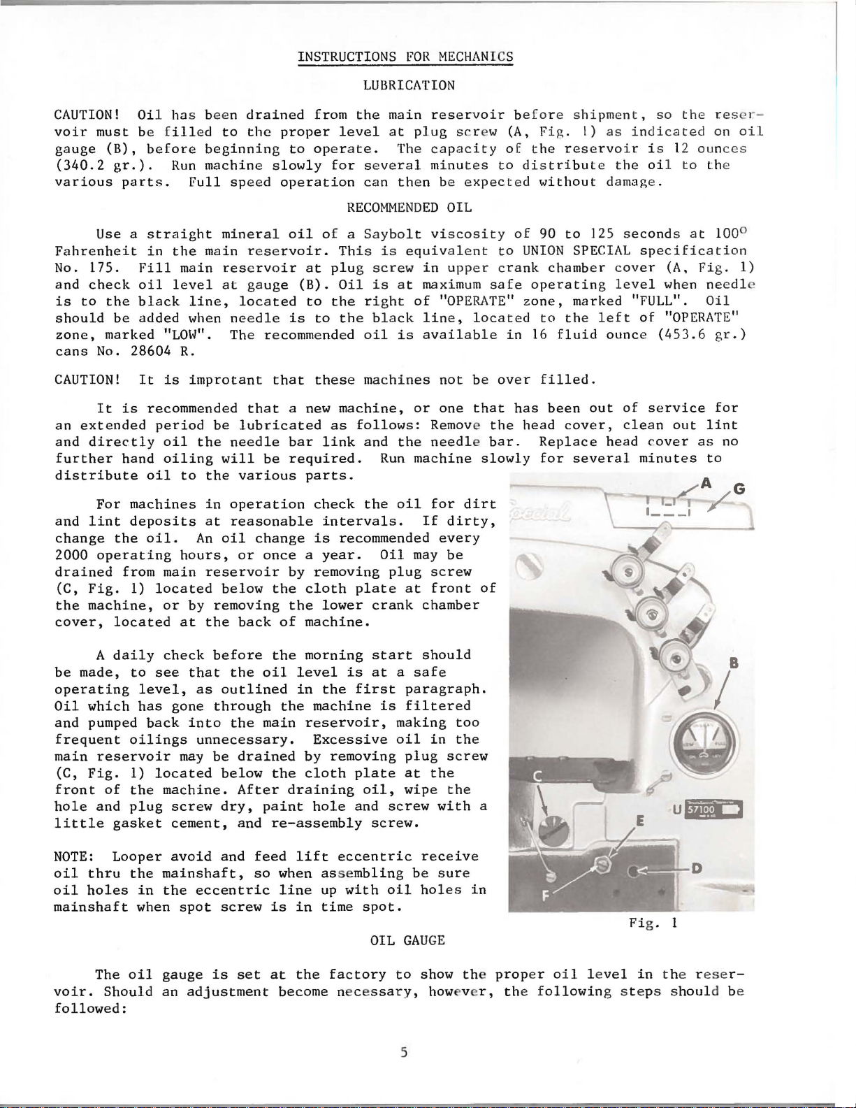
CAUTION!
voir
must
gauge
(340.2
various
Fahrenheit
No. 175.
and
is
should
zone,
cans
CAUTION!
an
and
further
distribute
and
change
2000
drained
(C,
the
cover,
(B),
gr.).
Use
check
to
the
be
marked
No. 28604
It
extended
directly
For
lint
the
operating
Fig.
machine,
located
Oi
l ha s been
be f
ill
before
Run
parts.
a
straight
in
the
Fill
oil
level
black
added
"LOW".
It
is
is
recommended
period
oil
hand
from
oiling
oil
machines
deposits
oil.
main
1)
located
or
at
ed
to
beginning
machine
Full
mineral
main
main
R.
to
hours,
reservoir
at
line,
when
needle
The recommended
improtant
be
the
needle
will
the
in
operation
at
reasonable
An
oil
reservoir
below
by
removing
the
drained
the
proper
slowly
spe
ed
operation
reservoir.
gauge
located
that
that
lubricated
be
various
change
or
once a year.
the
back
of
from
level
to
operate.
for
oil
of a
This
at
plug
(B).
Oil
to
the
is
to
the
these
a new
bar
required.
by
the
machine,
as
link
parts.
check
intervals.
is
recommended
removing
cloth
lower
machine.
the
main
several
can
RECOMMENDED
Saybolt
is
screw
is
right
black
oil
machines
follows:
and
Run
the
Oil
plate
crank
at
The
then
equiv
at
is
the
machine
oil
may
plug
at
plug
in
maximum
of
line,
available
or
If
chamber
reservoir
capacity
minutes
be
OIL
viscosity
alent
upper
"OPERATE"
not
one
Remove the
needle bar.
for
dirty,
every
be
screw
front
scr
ew (A, Fig.
of
to
expected
to
crank
safe
located
in
be
over
that
slowly
dirt
of
b
efo
r e
t he
distribute
without
of
90
UNION
chamber
operating
zone,
to
16
fluid
filled.
has
been
head
Replace
for
shipment, so
I)
as
indicated
reservoir
to
125
SPECIAL
marked "FULL".
the
left
out
cover,
several
i s 12 oun
the oil
damage.
seconds
specification
cover
level
of
ounce
of
service
clean
head
cover
minutes
(453.6
the res -r -
on
ces
to th
e
at
100°
(A,
Fig.
when ne
"OPERATE"
out
Oil
as
edl
gr.)
for
lint
no
to
oil
1)
e
A
be
made,
operating
Oil
which
and
pumped
frequent
main
reservoir
(C,
Fig.
front
hole
little
NOTE:
oil
oil
mainshaft
voir.
followed:
of
and
Looper
thru
holes
The
Should
daily
to
level,
has
back
oilings
1)
the
plug
gasket
the
in
when
oil
check
see
that
as
gone
into
unnecessary.
may
located
machine.
screw
cement,
avoid
mainshaft,
the
eccentric
spot
gauge
an
adjustment
before
the
outlined
through
the
be
drained
below
After
dry,
and
and
feed
so
screw
is
set
the
morning
oil
level
in
the
the
machine
main
paint
reservoir,
Excessive
by
the
cloth
draining
hole
re-assembly
lift
when asse
line
is
at
become nece
in
the
up
time
start
is
at a safe
first
is
removing
plate
oil,
and
screw.
eccentric
mbling
with
spot.
OIL
factory
ssary,
should
paragraph.
filtered
making
oil
in
plug
screw
at
the
wipe
screw
oil
GAUGE
to
5
the
with
receive
be
sure
holes
show the
how v r, the f
too
the
in
a
prop
er oi l l e
ollowin
Fi
vel
in
g s
teps shoul
g. I
the rese
B
I
r-
d be
Page 6
1.
2.
3.
4.
5.
6.
7.
8.
Place
Remove
drain
Make
Remove
Fill
press
Loosen
Tighten
cover.
Add
of
sure
main
the
left
to
the
oil
"OPERATE"
the
the
oil
lower
shaft
lock
or
left
lock
so
machine
oil
reservoir
from
the
all
oil
crank
reservoir
bushing
nut
(E) on
right
of
"OPERATE"
nut
that
gauge
zone,
OIL
GAUGE
upright
reservoir.
is
chamber
to a level
(D,
until
(E) and
marked "FULL".
on a
plug
drained
Fig.
the
the
zone,
replace
needle
cover,
calibrating
gauge
(Continued)
level
screw
from main
even
1).
marked
rests
table
(C,
located
with
needle
plug
on
or
Fig.
reservoir.
at
the
screw
rests
"LOW".
screw
the
(C) and
black
bench.
1) and
the
back
bottom
(F),
and
on
the
line,
tip
machine
of
the
contour
turn
black
lower
located
machine.
of
the
line,
crank
forward
the
screw
located
chamber
to
the
to
knee
to
right
of
needle
upper
is
tilted
bed
not
as
in
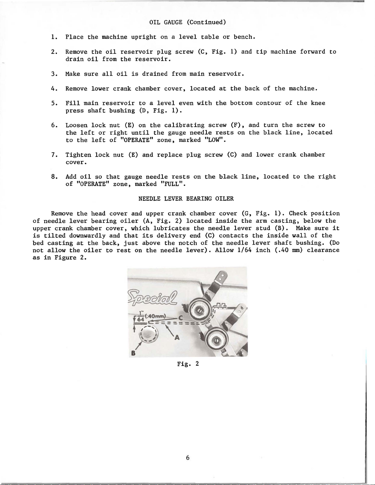
Remove
crank
casting
allow
Figure
the
head
cover
lever
downwardly and
the
bearing
chamber
at
the
oiler
2.
cover,
back,
to
rest
and
oiler
which
that
just
NEEDLE
upper
(A,
lubricates
its
above
on
the
LEVER
crank
Fig.
delivery
2)
the
needle
Fig.
notch
BEARING
chamber
located
the
needle
end (C)
of
the
lever).
2
OILER
cover
inside
lever
contacts
needle
Allow
(G,
the
1/64
Fig.
arm
stud
the
lever
inch
1).
casting,
(B).
inside
shaft
(.40
Check
below
Make
wall
bushing.
mm)
position
the
sure
of
clearance
it
the
(Do
6
Page 7

FILL
MAIN
RESERVOIR
HERE
Thread
clarity.
The
oil
must
be
and add
filled
oil
zone marked
keeping
refer
the
to
paragraphs
machine
has
been
before
when
needle
"LOW".
main
reservoir
THREADING
as
indicated
drained
starting
is
to
The machine
filled
on
"LUBRICATION"
AND
from
to
the
OILING
above.
the
machine
operate.
black
is
automatically
is
necessary.
and
CAUTION!
FILL
ALL
OIL
BEFORE
MACHINE
BEFORE
DIAGRAM
The
STARTING.
HAS
SHIPPING.
FOR
looper
STYLE
threading
before
Maintain
line
located
lubricated
For
further
"RECOMMENDED
RESERVOIRS
BEEN
DRAINED
57100 C
has
shipping
oil
level
to
the
and
in
left
and no
lubricating
OIL".
FOR
CORRECT
OIL
LEVEL
NEEDLE
SHOULD
OPERATE
Fig.
been ent
the
reservoir
"OPERATE"
of
the
"OPERATE"
oiling
instructions
OF
GAUGE
BE
IN
POSITION
3
arged
position
other
for
than
7
Page 8

ALIGNING
THE
NEEDLE
BAR
Insert
bar
so
that
turn
needle
quired.
tion
left
respect
looper
needle.
to
the
able.
the
direction
the
accomplished
drive
tap
with a small
quired.
plate,
ervoir
rocker
Looper
ring
from
ring
metal
Tighten
Insert
until
side
to
point
If
looper
If
the
looper
rear.
Moving
lever.
To
throat
back
shaft,
drive
between
the
looper
until
contact
move
a new
the
bar
the
the
of
the
the
again
the
point
distance
is
greatest
Moving
of
as
To
move
plate
cover,
toward
lever
it
drive
with
set
needles
(A,
Fig.
clamp
looper
point
looper
motions
the
the
follows:
and
drive
of
right
moves
will
looper
it
in
looper
move
hammer,
stud
support,
then, a light
the
(E,
the
lever
the
of
needles
correspond
4),
screw.
SYNCHRONIZING
in
the
the
looper
needle
point,
to
the
synchronize,
be
the
from
the
when
stud
forward
Fig.
lever
(E) and
bed
the
drive
the
opposite
drive
Loosen
to
driectly
operator,
5)
bed
casting.
rocker
casting.
(Type and
loosen
looper
(B).
then
left,
same. A
eye
pulley
shaft
lever
the
rear
(toward
oil
reservoir
tap
has
the
with the ver tical face
turn
of
on
is
an
shaft
oil
Size as
needle
LOOPER
rocker
(A,
Note
the
direction
clamp
(away
the
operator),
on
all
oil
All
Tighten
bar
AND
Fig.
the
handwheel
and
is
height
variation
the
needle
is
turned
synchronizing
shaft
screw
from
stud
top
the
that
seal
end
by
seal
requi
clamp scr ew (B)
NEEDLE
and
turn
5),
moving
height
even
of
acts
synchronizing
(D)
operator),
is
cover
looper
is
collar
play
compressing
collar
screw
MOTIONS
handwheel
of
in
the
with
the
eye
of
.005
to
the
in
the
stud
the
of
all
that
remove
and
drive
required.
and
must
make
(D).
be
red)
of
to
the
the
eye
reverse
the
left
of
inch
point
operating
(C)
reverse
stud
the
looper
a
light
is
the
cloth
oil
lever
Note:
an
removed
the
"O"
metal
and
the
and
in
left
of
direction
side
the
(.127
of
to
.
is
reres-
"O"
to
align
needle
turn
operating
is
even
the
needle
of
needle
mrn)
the
guard.
bar
until
the
with
is
needle
as
re-
direc-
with
with
right
respect
allow-
To
the
the
check
With
the
the
looper
location
Fig.
of
at
5
the
the
center
extreme
line
right
of
tion
move
over
should
looper
sary,
the
clamp
can
tween
and
er
(Fi
rod
nut
threaded
looper
be
the
lever stud
g.
end
the
right
bearing,
(F,
locate
rocker
loosen
screw.
checked
the
center
center
5).
of
its
travel,
looper
using
Fig.
drive
If
5)
stud.
against
cone
the
clamp
lever
gauge
with a scale.
line
and
should
and
The
(G).
the
be
connec-
gauge
place
left
the
right
If
screw
(E)
is
not
of
the
center
4
1/16
No. 21227
hole
end
of
side
adjustment
(D)
and
as
required.
available,
The
distance
looper
line
of
inch
Fig.
4
CX.
in
g.
•1ge
the
gauge
of
the
is
neces-
reposition
Tighten
se
ttin
be-
rocker
the
loop-
(103.19
Re-
con
mrn)
g
e
8
Page 9

SETTING
THE
LOOPER
Inser t t
er g
au
ge
the center of the two
wh
en the
this
adjustment
recheck the
i s
5/32 inch
loop
Fig.
adjustment.
wo
er
6
new ne
is
at
may
edles
(3.97
needles
its
prove
in
the
mm),
farthest
can
has a left
turn
5/32
nut
vertical
of-feed,
hind
brushes,
the
lock
(G)
wise
ing
Holding
helpful.
set
(B)
be
used
If
the
inch
(D).
The
the
needle
If
screw
as
required.
sets
it
counterclockwise
needle
to
position
adjustment
hand
connecting
(3 . 97
Then
position
looper
if,
needle,
but
adjustment
the
looper
Tighten
seat,
the
looper
the
point
advantageously
mrn)
nut
as
does
(B).
(F,
Fig.
looper
to
of
to the
is
thread)
rod
dimension.
(C).
and
is
set
it
moves
its
point
not
is
6)
Turning
the
lock
type
and
(A,
Fig.
the
right.Looper
in
required,
and
forward
Make
does
not
correctly
to
(A,
pick
at
necessary,
and
turn
stop
to
the
acts
front
screw
size
6)
looper
making
loosen
nut
or
Retighten
sure
bind
the
left,
Fig.
the
stop
screw
rear
the
while
when
as
so
is
(D)
on
backward
the
after
in
line-
7)
rear
loosen
clockand
reverse.
making
setting
specified.The
the
distance
5/32
gauge
this
left
be-
screw
turn-
inch
No.
adjustment.
nut
(C,
connecting
to
both
ball
adjustment.
of
is
obtained
between
(3.97
21225-5/32
Fig.
obtain
nuts,
joint
6)
rod
first
Fig.
loop
mrn),
(it
(E),
the
is
7
and
-
in
Fi
g. 8
1/64
the
pressure
screw.
of the nee
inch
corner
The
(.40
on
dles
may
the
point
rnrn)
be
slightly
heel
of
by
adjusting
SETTING
The
height
is
correct
eye
is
of
the
moving
of
this
loosen
up
or
Care
must
ment
ating
and
retainer
cannot
of the
justment,
right
following conditions
(.40
of
the
and
The loop
direction
the
rnrn)
be
the
looper
1/64
looper,
to
needle.
screw
down
be
as
left
left
(B).
over
obtained
altered
looper
the
when
inch
wh
the
left,
(B)
as
required
taken
needle
the needl
sides
SETTING
er
corner
At
the
by
in
will
loop
HEIGHT
of
the
(.40
en
If
and
and
until
th n have to
er
OF
the
needle
top.of
mrn)
the
point
is even
adjustment
reposition
and
not
to
bar
while
es
are
of
the
THE
LOOPER
loop
r e
prevail:
the
of
the
this
looper,
then the
loosening the
the
point
requir
rocker.
NEEDLE
bar
the
left
below
of
with
is
retighten
disturb
making
to
needle
AND
tainer
(1)
looper
recess
the
from
back
distance
ed
direction
be
BAR
(A,
Fig.
8)
needle's
the
underside
looper,
the
l e
ft
side
necessary,
needle
have
LOOP
are set correctly when the
Turn the handwh
(A,
prong
looper
reset
bar
(A)
screw.
the
align-
this
ad-
equal
slots
Fig.
is
under the
to
which the
clearance on
in
throat
RETAINER
9)
moving
should project
front
set screw (C) and a
with
whil
e r etighte
r espe
(Fi
prong projects
eel
pron
g.
ct
Fig.
plate.
i n the op e
to the
g of the
1/64
9).
ning th
to the
9
both the
right
loop
inch
I f
this
over
pplyin
e
back
r-
g
9
Page 10

(2.)
tainer
and
the
drawn
that
When
there
underside
between
passes
the
looper
should
them.
throu
SETTING
moves
be
a minimum amount
of
the
The
gh
the
THE
LOOPER
to
the
prong,
adjustment
throat
plate
or
AND
LOOP
right
and
of
just
enough
is
made by means
and
bears
RETAINER (Co
passe
s under the
clearan
ce
to perm
against
ntinued)
prong
between the
i t a
piece
of a small
the
top
top
of
screw
of
of
the
the
of
paper
(A,
loop
loop
the
to
Fig.
retainer.
re-
looper
be
10),
Fig.
If
throat
front
dog
CAUTION:
of
(A,
feed
(D)
plate,
teeth,
is
set
looper.
Should
Fig.
rocker
does
10
feed
properly.
See
13)
not
dog
loosen
and
that
it
be
which
to
desired
bind
Set
the
there
teeth
(1.19
and
plate
Adjust
under
this
to
teeth
nut
counterclockwise
there
necessary
hold
after
is
equal
extend
mm)
above
are
parallel
at
high
the
the
feed
setting.
hold
are
position
feed
not
(A, Fig. 12)
is
sufficient
to
the
feed
making
feed
dog
clearance
the
depth
the
with
point
supporting
dog,
Screw
dog
in
parallel
and
to
raise
move
rocker
and
this
the
retighten
adjustment.
SETTING
(A,
of a tooth
throat
the
of
travel.
screw
to
mainta
(D)
is
position.
with
turn
the
space
feed
(B)
onto
THE
Fig.
on
all
plate
throat
(C),
i n
used
the
screw
front
between
dog
to
the
screws.
FEED
11)
in
sides.
or
(B)
teeth.
underside
the
left
feed
Make
DOG
the
throat
See
that
approximately
clockwise
Retighten
or
rocker
sure
of
right,
shaft
the
to
feed
plate
the
lower
nut
feed
(B)
tips
3/64
when
dog
and
loosen
(C),
rocker
of
inch
the
screws
and
so
the
feed
top
move
arm
have
desired
the
feed
loosen
the
feed
rocker
ward
tighten
When
equal
stitch
Should
dog
nut
rocker
and
or
backward
nut.
the
handwheel
clearance
length.
it
be
forward
(E,
Fig.
move
Fig.
12
necessary
13)
arm
to
the
feed
as
needed
is
on
both
or
backward,
which
the
rocker
turned
ends
to
move
clamps
feed
and
re-
for-
in
of
the
the
operating
throat
direction
plate
slots
the
with
Fig.
feed
feed
13
dog
travel
should
set
to
10
Page 11

Set
nut
(F,
ulating
of
the
"S".
toward
(moves
prevent
the
"U"
the
Fig.
stud
cloth
Turning
the
"S")
stitch
destructive
shaped
stitch
13)
1/2
and
turning
plate,
the
screw
and
regulating
key
slot
to
required
turn
the
in
the
clockwise
turning
stud
damage
in
CHANGING
length.
(it
has a left
stitch
head
of
shortens
it
in a counterclockwise
toward
to
the
feed
the
ferrule
This
adjusting
the
main
the
drive
(K).
STITCH
is
hand
shaft
the
"L").
bearing,
LENGTH
accomplished
thread)
screw
stitch
Retighten
on
(G)
(H),
(moves
direction
the
the
located
which
the
Key
by
loosening
end
of
under
is
marked
stitch
lengthens
locknut
screw
the
the
stitch
the
left
with
regulating
the
securely.
(J)
must
lock-
regend
"L" and
stud
stitch
To
engage
NOTE:
rear
operation.
move
screws
withdrawn.
directly
the
sealed
assemble,
end
damage. Check
Feed
contact
A
clearance
possible,
the
needle.
needle
loosen
clockwise
Any
needle
The
nut
(A)
When
part
number 28604
bearings
of
shafts
Dog".
Set
the
the
needle,
To
guard
screw
change
guard
feed
This
(F).
and remove
Loosen
packing
from
reverse
Also
rear
of
yet
until
move
to
rocker
can
Remove
the
are
first,
for
rear
.005
have
as
required,
(F),
raise
in
stitch
setting.
assembly
be
Allen
bearings
tube
P.
replaced
the
twisting
proper
check
needle
of
the
inch
its
the
point
needle
and
turn
it.
length
may
accomplished
feed
rocker
stop
collar
screw
to
avoid
Greased
procedure
adjustment
to
see
SETTING
guard
right
(.127
vertical
guard
and
Retighten
(L) and remove
the
parts
they
slightly
that
(C,
needle
mm)
of
the
forward
retighten
screw
will
require
arm
on
contamination.
bearings
should
described
there
THE
Fig.
is
face
looper
(G)
screw
necessitate
lubrication
as
follows:
(D)
from
right
must
of
REAR
(D)
permissible.
approach
or
clockwise
end
be
are
be
in
when
feed
is
NEEDLE
12)
when
(E),
backward,
screw.
(F)
after
a
Loosen
machine
of
shaft
shaft
clean
Tube
located
pressed
the
entering
dog
no
binding
horizontally
at
within
moving
to
(M).
and
of
in
previous
as
described
GUARD
its
most
It
about
merely
To
raise
lower
guard
corresponding
or
repair
nuts
by
grease
grease
at
flush
the
at
should
to
is
(E,
rocking
(C).
Now,
(N,
P,
with
paragraph.
grease
any
so
that
forward
3/64
the
left,
loosen
or
lower
needle
properly
The
repack
should
can
under
point.
be
guard
after
F,
Fig.
slightly.
shaft
be
Fig.
the
seals
it
point
set
inch
is
screw
needle
set.
change
years
13) and
can
bearings.
be
applied
supplied
13).
casting.
Start
to
prevent
"Setting
does
not
of
as
low
(1.19
even
(F),
guard,
and
counter-
in
of
Loosen
now
If
grease
tapered
the
quite
travel.
as
mm)
with
move
the
re-
be
under
To
of
the
NOTE: A change
rear
needle
The
thread
begins
within
is
its
lever
machine
Retighten
binding
to
1/8
entirely
highest
If
adjustment
screw
and move
at
screw.
in
guard
tension
function
inch
released
position.
(A,
Fig.
any
point.
stitch
setting.
THREAD
as
(3.18
is
tension
After
length
TENSION
release
the
presser
mm)
of
when
the
needed,
14),
located
disc
adjustment
will
RELEASE
is
foot
the
end
presser
loosen
at
separator
there
require
set
of
foot
tension
the
a
correctly
is
raised
its
travel
has
release
back
as
required.
should
11
change
when
to
reached
of
the
be
no
and
in
it
Fig.
A
l.
14
Page 12

The
to
remove
pressed.
lower
surface
presser
plate.
needle
foot
a
setting
presser
surface
If
bar
down
screwdriver
height
the
Also
of
foot
adjustment
on
by
foot
of
presser
there
of
head
opening
resting
is
in
the
to
turning
can
the
presser
foot
should
the
presser
on
is
needed,
the
low
throat
obtain
handwheel
be
removed
SETTING
when
be
in
the
the
throat
position
plate
the
1/16
as
HEIGHT
bar
(A,
the
foot
approximately
bar
connection
bed
when
plate,
turn
handwheel
and
loosen
surface,
inch
so
that
mentioned
(1.59
needle
Fig.
lifter
the
pry
in
OF
PRESSER
15)
1/16
and
foot
with
in
screw
up
presser
mm)
bar
previous
is
set
lever
inch
guide
lifter
the
feed
operating
(C).
setting
is
in
paragraph.
BAR
correctly
(B,
Fig.
(1.59
(B,
Fig.
lever
dog
direction
Then,
bar
connection
and
its
high
14)
mm)
15) and
is
down
while
tighten
position
if
it
is
is
fully
clearance
the
released
below
the
until
holding
and
screw.
possible
debetween
bottom
and
throat
the
presser
guide
Check
and
see
the
with
if
Remove
bar
(A),
be
able
to
be
true
position
the
presser
hole
only
tension
(19.05
in
Regulate
enough
if
to
corded
presser
is
Fig.
mm)
both
not
move
and
with
foot
the
pressure
placed
15
above
needles
already
freely
operate
respect
clamp
foot.
presser
on
on
the
the
attaching
SETTING
(D,
Fig.
in
place.
on
the
presser
the
machine.
to
the
screw.
the
fabric.
the
wise
reverse.
take-up
located
needle
(C),
surface
top
of
needle
when
completed
stroke.
ting
thread
for a larger
the
needle
eyelet
eyelet
Replace
PRESSER
spring
presser
needle
increases
SETTING
Set
the
wire
adjacent
bar
so
that
is
the
bar
the
needle
Lower
for a smaller
loop,
(D)
hole
screw
THE
15) and
Do
not
bar.
This
guide
regulating
foot
This
bar
thread
even
holes
thread
its
thread
so
is
in
the
NEEDLE
needle
(B,
its
with
bar
downward
this
and
loop.
that
is
3/4
(Fig.
PRESSER
put
tighten
will
on
top
the
needles
FOOT
to
the
the
pressure,
THREAD
thread
Fig.
to
the
eyelet
upper
the
in
the
eyelet
has
set-
needle
raise
Set
frame
the
inch
16).
FOOT
presser
Place a piece
allow
of
PRESSURE
screw
feed
knurled
head
of
16),
it
foot
the
clamp
the
the
throat
and
check
(A,
Fig.
the
work
screw,
the
counterclockwise
TAKE-UP
(E) on
screw
of
fabric
presser
plate.
for
16)
uniformly
located
machine.
WIRE
Fig.
to
(F).
foot
clearance
so
that
Turning
AND
FRAME EYE
B
the
presser
It
in
the
to
Now
tighten
it
when a
directly
it
acts
16
the
should
machine
find
its
in
needle
exerts
slight
behind
clock-
LET
12
Page 13

THREADING
Draw t he
iece
p
Pull
to
produce
The
thread
The
(B)
contr~ls
tion.
take-up
The
trol
of
More
and
set
traingle
ed
down
as
the
of f
looper
is
looper
It
(C)
height
the
toward
may
stitches.
looper
loo
per
abric. R
the
needle
uniform
thread
just
sufficient
thread
the
amount
should
and
be
the
and
looper
looper
thread
the
be
wiped
moves
and
needle
efer to
thread
stitches
tension
SETTING
retaining
of
set
laterally
tip
parallel
the
lateral
thread
is
takeup.
under
This
to
can
the
threading
THREAD
through
on
the
should
to
steady
THE
slack
as
the
given
However,
the
be
checked
left.
threads
into
diagram
TENSIONS
the
eyelets
under
be
the
thread.
LOOPER
THREAD
finger
thread
so
with
in
that
the
adjustment
looper
to
blade
the
if
moves
stitch
it
of
by
the
(Fig.
surface
set
so
(A,
Fig.
the
it
is
discs.
of
is
the
looper,
observing
machine
3).
and
set
of
the
that
the
RETAINING
17)
located
system
and
midway
the
retaining
to
the
left.
when
raised
the
too
causing
the
and
the
needle
fabric.
tension
FINGER
can
between
finger
retaining
high,
action
start
on
on
the
be
moved
the
finger
the
triangle
of
the
operating
thread
the
looper
cast-off
to
two
discs
affects
is
looper
skips
looper
on a
tension
support
any
posi-
of
the
con-
raised
thread
or
pull-
thread
the
Fig.
17
13
Page 14

...
···········--------····
..
K
14
Page 15

R
ef.
No.
THREAD
Part
No.
EYELETS, FEED
LOOPER
LIFT
ECCENTRIC,
DRIVING
NEEDLE
AND
LOOPER
Description
ROC
BAR,
KER
HANDWHEEL
PAR
TS
ASSEMBLY,
Amt.
Req.
10
11
12
13
14
15
16
17
18
19
20
21
22
23
24
25
26
27
28
29
30
31
32
33
34
35
36
37
38
2
3
4
5
6
8
9
1
7
56458 A
52170
539
56458
61434
29476
22894 M
57845 B
39543 N
56321
22574
61321
56321 D
56321
22894
57117
52107
29105
22587 K
56343
56343 E
22559 A
56344
29192
51745
57113
15465
22829
G
NM-080
77
J
L
H
AB
56
c
56
GV
56 v
88
AG
c
c
98
719
AD
F
88
258 A
96
Needle
Needle
Needle
Needle
Washer,
Feed
throw------------------------------------------------
Thrust
Handwheel
Needle
Needle
Needle
Screw------------------------------------------------Looper-----------------------------------------------Looper
Looper
Looper
Screw-------------------------------------------------
Bar
Thread
Thread
Thread
Lever
for
Lift
Screw--------------------------------------------Eccentric
Screw-----------------------------------------
Washer
Screw--------------------------------------------Retaining
Handwheel-----------------------------------------
Pulley--------------------------------------------
Screw-----------------------------------------
Bar,
Tapered
Wedge-----------------------------------------Clamp
Drive
Bearing
Ball
Oil
Splasher--------------------------------------
Bearing
Rocker
Set
Screw-----------------------------------------
Stop
Rocker
Looper
Looper
Looper
Screw----------------------------------------Lock
Lock Nut
Thread
needle
Eccentric
Assembly------------------------------------
marked
Stop
Collar-----------------------------------
Lever
Cap
Joint
Cap
Screw----------------------------------------
Rocker
Rocker,
Rocker
Nut------------------------------------------
Screw------------------------------------
Eyelet-----------------------------Take-up
Frame
Link
for
Plate-----------------------------------
Screw,
Guide
Screw,
Frame-----------------------------------
Assembly--------------------------------
Wire
---------------------------Eyelet---------------------------Eyelet----------------------------
guard------------------------------
Assembly,
Assembly---------------------------
feed
Pin---------------------------------
Cone
Cone--------------------------------
bar----------------------------
"EY"-------------------------------
Crank
marked
Assembly---------------------
upper--------------------------
Fork-----------------------------
lower--------------------------
Stud---------------------------
.080
inch
"AE"------------------------
(2.03
l
l
1
l
l
rnrn)
1
1
1
1
2
l
3
1
l
l
2
1
1
l
l
l
1
1
2
l
l
2
l
l
l
l
l
l
1
2
l
l
l
15
Page 16

16
Page 17

PRESSER
FOOT,
AND
THROAT
LOOPER
PLATE,
THREAD
FEED
TAKE-
DOG,
UP
CLOTH
PARTS
PLATE
COVER
R
10
11
12
13
14
15
16
17
18
19
20
21
22
23
24
ef.
No
1
2
3
4
5
6
7
8
9
.
Par t
No.
8620
K-1/8
91
8624
K-1/8
28
c
27
v
28
8605 J
57757 A
52904 G
51204
22569 D
69
H
87
u
22768
77
52904 E
50-216
51204 A
73
A
56381-222
22845 B
22760 A
35772
51281
H
AC
Blk.
Desc
ript
i on Re
P
resser
hroat
T
Feed Dog,
Cast-off
Cast-off
Looper
Screw,
Washer,
Screw,
Screw,
Screw,
Retaining
Cast-off
Screw,
Cloth
Foot------------------------------------------
Screw---------------------------------------------
Plate------------------------------------------
Screw,
Loop Re
Screw,
Dowel
Plate
Pivot
Screw-------------------------------------------
Washer-------------------------------------------Cloth
for
adjustin
tainer,
for
loop retainer--------------------------
16
teeth
Support
Wire-----------------------------------------
Thr
ead
for
cast-off
for
for looper
for
retaining
for
cast-off
Finger
Pin-----------------------------------------
Wire
for
cast-off
Screw---------------------------------------
Plate
Plate--------------------------------
Retaining Finger------------------------
cast-off
Support
Support---------------------------------
Cover-------------------------------------
Cover
g
loop
retainer----------------
marked
per inch
support
thread retaining
wire
wire------------------------------
"AY"------------------------
(1.59
plate---------------------
support
fing
Spring--------------------------
plate
er
support
support---------------------Bracket----------------------
mm
screw-------------finger-------------
bracket-----------
per
tooth)-------
Am
t.
q.
-
1
1
1
1
1
1
1
1
1
1
2
2
1
1
1
1
1
1
1
1
1
~
-
3
3
1
17
Page 18

Special
Wants
to
Help
\bu
Cut
Maintenance Costs
Union
help
maintenance costs: a record keeping system
spot machines requiring
and a parts
Machine
Repair-prone machines
eat
spot these problems,
variations
system using cards
The
Record" card
plant. When a repair is required, the card is pulled
the file and the repair date, parts used, and
are entered in the spaces provided and the card is refiled.
DAT
Special is offering
pinpoint
and reduce
inventory
Maintenance
up
your
maintenance dollars in short order. To help
of
a simple maintenance record keeping
provided
two
your
abnormally
system
to
Records
or
inexperienced operators can
Union
Special suggests
by
practical systems
sewing machine
high maintenance,
speed routine repairs.
Union
Special.
first system utilizes a "Machine Maintenance
I:
MAKIU I a
NAM
aT•uto'-
(Form
I
PART
MACHINE
I
uaco
237)
for
each sewing machine
MAINTENANCE RECORD
aTTL&
TYP
I N
EID
I.C
I I I
.
...
.
OA
"'
I
S 'I'M
a
«llliALN
aCM,.P'Aft
O
TU
231-
fO~~aintenance
f'<\ad""
Recor
dear
d
to
two
their
..
CO
to
help
from
cost
bAT
I P U RCH
in
COOT
a
f.-
~~-.nn
forelady
Request Card" and gives
the
their
transferred
kept
invaluable tool
Repair
machines require
little
repairs. To alleviate this situation,
recommends
parts
machine they operate.
mechanics can be eliminated with an orderly
inventory
is
spare parts.
machine
parts
considered.
Style 39500 QB
or
foreman fills
time
the repair
cost, and the
to
the permanent "Machine Repair Record"
in
the office.
Whichever system
to
reduce needless maintenance costs.
Part
Inventories
out
it
to
work
is started, the parts used and
completion
is
used, management now has an
While record keeping tells
abnormally
to
help reduce the
that
inventory
system
Excessive machine
of
the
most
no
longer a need
Long
downtime
inventory
is small when the overall savings are
downtime
manufacturers establish a
for
each type
downtime
commonly
to
cannibalize other machines
waits
for
deliveries are avoided and
is
kept
to a minimum.
the
top
of
a "Repair
a mechanic. He fills in
time
. This data is then
management
high maintenance,
caused by routine
Union
Special
of
sewing
and wasted hours by
needed parts. There
The cost
which
formal
in-plant
it
doe
for
of
s
a
-
The
second system is
detailed
information
on repair costs is desired . Two
record cards are used : a
(Form
(Form
234), and a "Machine Repair Record"
233)
. When a machine requires service, the
MACHINE
REPA
IR
RECORD
CARD
MAKER a NA
MC
DATil
...
r:.
u.•
fOlt~
hl'\e
f'<\aC
I
-
~
"
233-:rd
ReP
air
~
Rec
-
normally
- - _ . ,
.._
•a•-
••
used when
•• - ... U O
"Repair Request Card"
.........
:t:w
~~
L
card
I
I
•A'l~~a:
l'J~t>'-f
..
o
IN'IUoffOft
MA
• u e N Aill
MA
E:)!
CINIIIIH
~
a &
lo
I
NU M M&"
REPAIR REQUEST CARD
'r O•OII
G
, a&11"
fo. NO,
I;II
.
NO
.
PART
, • • • N
v--
fOlt~
ai<Re<\
ReP
TIMC
aT
...
Itn:o
11
WC COM
"'-CTII
"'IC:HA
D
N IC: 8 NO
--
·--
_ , _ ·-·---":::" !"; :
..
more
..
lti
AL
I
S USED
234-
uest card
-
1----
Hflfil,--
..,
,._
,.
• • a
..
e~l~ftll
-
-
-
-
-·
f.-
f-
~-
':
Part Number
39520A
39530
3959711
3
9524 B 3/32
or
39524 B 1/B
22524
3
9526
B
3950
5 B
39505
22528
93
11
22797 A
39!!
70
14077
39549
2258
8 A
39508
B
3950811
225646
39551
F
14077
22596
E
21225
1/8
154
GAS
For
free sample copies
and spare part
Presser foot
Presser
Presser foot sti
Throat plate markPd "V-
Throat plate marked "V·
Throat plate screw
Differentoal feed
Matn feed dog marked B. I
Chai
nong
ScrPu•
sJ\
l
s-pat'e
N . .. pper knife clamp stud
Lower
Screw for lower kn ife clamp
Lower looper
Upper loope r marked
Screw for upper looper
Needle clamp stud
Nut
for
Screw
Looper guage
Needles (spec•fy size)
inventory
Description
foot
h.nge
tch
or
feed
t~~-
•
1"\~\...'-"
\)aftS
knofe
needle clamp stud
for
needle droving
popular machines, contact
Representative
or
write direct
Minimum Spare
Parts Per Machine
spr
.ng
tongue marked "OS"
3/32
"
I/8"
dog.
16
teeth per inch
I'
• eth per inch
G
\..\St
"CC"
arm
100
of
the machine record cards
lists
for
your
to
a variety
local
Union
Union
Special.
of
the
Special
I
2
1
I
I
2
I
I
1
2
2
2
4
1
4
1
1
1
2
1
1
2
1
most
Page 19

Here
are
Oil
for
Specifications
Union
Sewing
roleum
mended
machines.
roleum
mount
high
mitters.
3.
used.
Specification
Specification
white
or
1.
For
use
roleum
quality
Where
UNION
oil,
viscosity
for
all
oil,
viscosity
with a maximum
where freedom from
Specification
oil,
viscosity
Specification
grease
It
is
similar
No.
3 grease
SPECIAL
SPECIFICATION
Viscosity S.S.U.
Flash
(Min.)
Pour
(Max.)
Color
A.S.T.M.
Neutralization
Viscosity
(0
Compounding
Copper
*Anline
*Used
Index
& D
Min.)
Corrosion
No.
with
Buna N
174
100
oiling
175 specifies a high
87 specifies a high
300
100
for
to
commercial
is
NO. 174 175 87
at
100°F
(Max.)
No.
(Max.)
(Max.)
Rubber
Special
Machines
specifies a high
seconds
applications
100
seconds at
A.S.T.M.
oil
seconds
use
not
at
specifies a general purpose
in ball bearings and trans-
N.L.G.I.,
obtainable,
90-125
350
20
3
0.10
85
None
1A
175-225
"0"
Retainers
quality
at
100°F.
on
color
staining is para-
100°F.
90-125
0.10
175-225
Recom-
high speed
quality
100°F.,
number
quality
grease
No. 2 may
300-350
350 350
20
1 3
85
None
1A 1A
pet-
pet-
water
of
pet-
No.
be
20
0.10
85
None
175-225
NOTE
1:
The
use
of
non-corrosive additives
meeting above classification is desirable
essential. These
1.
2.
3.
4.
5.
These additives
and
not
separate.
NOTE
2:
shall
not
1.
2. Tackiness
3. Lead soap
4. Detergents
may
Oxidation
Rust
Lubricity
Anti-oxidants
Film
removable
Oils
be used
Extreme
inhibitors
inhibitors
additives
strength
must
containing
at
any
pressure
or
additives
include:
additives
be
completely
by
wick
feeding
the
following
time:
additives-corrosive
adhesive additives
soluble
nor
type
UNION SPECIAL
IIN!SI
QUAIIIY
CORPORATION
in
but
in
the
shall
they
additives
oils
not
oil
Page 20

.,.o
..
...
'
q
WORLD'S
p.llf
FINEST
QUALITY
*
,,
'"
INDUSTRIAL
SEWING
MACHINES
UNION
SPECIAL
maintains sales
facilities throughout the world. These offices
aid
you
in
the selection of the right sewing
equipment for your
Special representatives
tory trained
promptly
tion, there
you. Check with
serve
ATLANTA,
BOSTON,
CHICAGO,
DALLAS, TEXAS
LOS ANGELES, CAL.
NEW
PHILADELPHIA,
GA.
MASS.
YORK, N.
ILL.
and
and
is
a Union Special Representative to
Y.
PA.
particular operation. Union
and
service men
are
able
to serve your needs
efficiently. Whatever your loca-
him
today.
MONTREAL, CANADA
TORONTO,
BRUSSELS, BELGIUM
LEICESTER,
LONDON,
PARIS, FRANCE
STUnGART,
and
service
are
CANADA
ENGLAND
ENGLAND
GERMANY
will
fac-
Representatives
I
ndustrial
UNION SPECIAL
400
N.
FRANKLIN
and
cities
distributors
throughout
CORPORATION
ST.,
In
all
Important
the
world.
CHICAGO,
ILL.
60610
 Loading...