

Page 1
MANUAL NO.
IP9107-GR
First Edition
STYLES
56500R
56900P
56900R
ADJUSTING INSTRUCTIONS
AND ILLUSTRATED PARTS LIST
04/28/09
SERIES 50000 - FLAT BED MACHINES
Page 2

MANUAL NO. IP9107-GR ADJUSTING INSTRUCTIONS & ILLUSTRATED PARTS LIST
FOR 50000 SERIES MACHINES
FIRST EDITION COPYRIGHT 2006
BY
UNION SPECIAL CORPORATION RIGHTS RESERVED IN ALL COUNTRIES
PRINTED IN U.S.A. APRIL 2006
2
Page 3

PREFACE
This technical manual has been prepared to guide you in the maintenance of your new Union Special machine. Careful
attention to the instructions for operation and adjustment of these machines will enable you to maintain the superior
performance and reliability designed and built into every Union Special machine.
The adjusting portion of this manual explains in detail the proper setting for each of the components related to forming the
stitch and completing the functions of the machine. Illustrations are used to show the adjustments and reference numbers
are used to point out specific items discussed.
Adjustments are presented in sequence so that a logical progression is accomplished. Some adjustments performed out
of sequence may have an adverse effect on the function of other related parts.
NOTE: Instructions stating direction or location, such as right, left, front or rear of the machine are given relative to the
operator’s position at the machine unless otherwise noted. The handwheel rotates counterclockwise in operating
direction; as viewed from the right end of the machine.
To simplify identification of repair parts, the mechanisms are illustrated by exploded views. A numerical index at the back
of the manual will help you locate an item when only the part number is known.
Implementation of preventative maintenance procedures can bring about significant improvements in operator
productivity by avoiding costly equipment breakdowns. Wherever it becomes necessary to make repairs or replace parts
on your machine, be sure to insist on genuine UNION SPECIAL Repair Parts. These parts are designed specifically for your
machine and manufactured with utmost precision to assure long lasting service.
This manual has been comprised on the basis of available information. Future changes and/or improvements may
incorporate a slight modification of configuration in illustrations or part numbers.
3
Page 4

SAFETY RULES
1. Before putting the machines described in this manual into service, carefully read the instructions. The
starting of each machine is only permitted after taking notice of the instructions and by qualified
operators.
IMPORTANT! Before putting the machine into service, also read the safety rules and instructions from the
motor supplier.
2. Observe the national safety rules valid for your country.
3. The sewing machines described in this instruction manual are prohibited from being put into service until
it has been ascertained that the sewing units which these sewing machines will be built into, have
conformed with the EC Council Directives (89/392/EEC, Annex II B).
Each machine is only allowed to be used as foreseen. The foreseen use of the particular machine is
described in paragraph “STYLES OF MACHINES” of this instruction manual. Another use, going beyond
the description, is not as foreseen.
4. All safety devices must be in position when the machine is ready for work or in operation. Operation
of the machine without the appertaining safety devices is prohibited.
5. Wear safety glasses.
6. In case of machine conversions and changes all valid safety rules must be considered. Conversions
and changes are made at your own risk.
7. The warning hints in the instructions are marked with one of these two symbols:
8. When doing the following the machine has to be disconnected from the power supply by turning off
the main switch or by pulling out the main plug:
8.1 When threading needle(s), looper, spreader etc.
8.2 When replacing any parts such as needle(s), presser foot, throat plate, looper, spreader, feed
dog, needle guard, folder, fabric guide etc.
8.3 When leaving the workplace and when the workplace is unattended.
8.4 When doing maintenance work.
8.5 When using clutch motors without actuation lock, wait until the motor is stopped totally.
9. Maintenance, repair and conversion work (see item 8) must be done only by trained technicians or
special skilled personnel under consideration of the instructions.
10. Any work on the electrical equipment must be done by an electrician or under direction and supervision
of special skilled personnel.
11. Work on parts and equipment under electrical power is not permitted. Permissible exceptions are
described in the applicable sections of standard sheet DIN VDE 0105.
12. Before doing maintenance and repair work on the pneumatic equipment, the machine has to be
disconnected from the compressed air supply. In case of existing residual air pressure, after disconnecting from compressed air supply (i.e. pneumatic equipment with air tank), the pressure has to be
removed by bleeding.
4
Page 5

CONTENTS
PREFACE ................................................................................................................................................................... 3
SAFETY RULES ............................................................................................................................................................ 4
IDENTIFICATION OF MACHINES .............................................................................................................................. 6
MACHINE STYLES ...................................................................................................................................................... 6
THREADING AND OILING DIAGRAM ..................................................................................................................... 7
LUBRICATION ............................................................................................................................................................ 8
NEEDLES .................................................................................................................................................................... 8
NEEDLES (CONT.) ..................................................................................................................................................... 9
ADJUSTING INSTRUCTIONS ...................................................................................................................................... 9
NEEDLE BAR ALIGNMENT ........................................................................................................................................ 9
SYNCHRONIZING LOOPER AND NEEDLE MOTIONS............................................................................................ 10
SYNCHRONIZING LOOPER AND NEEDLE MOTIONS (CONT.) ............................................................................ 11
LOOPER SETTINGS .................................................................................................................................................. 11
LOOPER SETTINGS (CONT.) ................................................................................................................................... 12
NEEDLE BAR HEIGHT............................................................................................................................................... 12
REAR NEEDLE GUARD ............................................................................................................................................ 12
REAR NEEDLE GUARD (CONT.) ............................................................................................................................. 13
FEED DOG SETTINGS .............................................................................................................................................. 13
PRESSER BAR HEIGHT AND PRESSER FOOT .......................................................................................................... 13
PRESSER BAR HEIGHT (CONT.) .............................................................................................................................. 14
PRESSER FOOT PRESSURE ....................................................................................................................................... 14
NEEDLE THREAD TAKE-UP WIRE AND FRAME EYELET .......................................................................................... 14
CHANGING STITCH LENGTH ................................................................................................................................. 14
CHANGING STITCH LENGTH (CONT.) .................................................................................................................. 15
THREAD TENSIONS .................................................................................................................................................. 15
THREAD TENSION RELEASE .................................................................................................................................... 15
TORQUE REQUIREMENTS ....................................................................................................................................... 15
SPECIAL INSTRUCTIONS ......................................................................................................................................... 16
NEEDLE LEVER ......................................................................................................................................................... 16
ALIGNING MAINSHAFT TO CRANKSHAFT ............................................................................................................ 17
ORDERING REPAIR PARTS...................................................................................................................................... 18
ILLUSTRATIONS ........................................................................................................................................................ 18
IDENTIFYING PARTS ................................................................................................................................................ 18
TERMS ...................................................................................................................................................................... 18
SKIPPED STITCHES ................................................................................................................................................... 19
MAIN FRAME, THROAT PLATE SUPPORT, MISC. COVERS & OILING PARTS ....................................................... 23
MAIN FRAME, THROAT PLATE SUPPORT, MISC. COVERS & OILING PARTS (CONT.) ........................................ 25
MAIN FRAME, BUSHINGS, OIL GAUGE & LOOPER DRIVING PARTS .................................................................. 27
CRANKSHAFT, NEEDLE LEVER & LOOPER DRIVING PARTS .................................................................................29
CRANKSHAFT, NEEDLE LEVER & LOOPER DRIVING PARTS .................................................................................31
LOOPER ROCKER & CONNECTING ROD PARTS ................................................................................................. 33
MAIN SHAFT, TAKE-UPS & FEED DRIVING PARTS.................................................................................................. 35
MAIN SHAFT, TAKE-UPS & FEED DRIVING PARTS.................................................................................................. 37
NEEDLE BARS, HOLDERS & GUARDS, LOOPERS & LOOPER THREAD TAKE-UP PARTS ...................................... 39
DISC THREAD TENSION PARTS ............................................................................................................................... 41
TENSION & LIFTER LEVER PARTS ............................................................................................................................. 43
CLOTH PLATE, CLOTH PLATE COVER, FOLDER & OIL SHIELD PARTS ................................................................. 45
PRESSER FOOT, THROAT PLATE & FEED DOG PARTS ........................................................................................... 47
PRESSER FOOT, THROAT PLATE & FEED DOG PARTS ........................................................................................... 49
THREAD STAND PARTS & MISC. ACCESSORIES ................................................................................................... 51
NUMERICAL INDEX OF PARTS ............................................................................................................................... 52
NUMERICAL INDEX OF PARTS ............................................................................................................................... 53
5
Page 6

IDENTIFICATION OF MACHINES
Each UNION SPECIAL machine is identified by a Style number, which on these classes of machines, is
stamped into the style plate affixed to the right front of the machine.
The serial number is stamped in the casting at the right rear base of machine.
CLASS DESCRIPTION (56500)
Advanced high speed, high throw, flat bed machines. Two needles, independent row, two loopers,
enclosed automatic lubricating system. Maximum recommended speed 6000 R.P.M. Maximum work
space to right of needle bar 8 1/4 inches (209.6mm).
MACHINE STYLES
56500R Typical application - For attaching riser to dungarees, piecing sleeves on denim jackets and for
attaching overall bibs made of medium heavy to heavy weight materials.
- Seam specification 401 LSc-2
- Type 147 GKS needle
- 16 and 18 gauge
CLASS DESCRIPTION (56900)
Advanced high speed, high throw, flat bed machines. Three needles, independent row, left needle in
front, three loopers, enclosed automatic lubricating system. Maximum recommended speed 6000
R.P.M. Maximum work space to right of needle bar 8 1/4 inches (209.6nun).
MACHINE STYLES
56900P Typical application - For attaching risers to the back of jeans made with medium heavy to
heavy weight materials.
- Seam specification 401 LSc-3
- Type 147 GKS needle
- 8 and 9 gauge
56900R Typical application - For seat seams, outseam or inseam on jeans made from heavy weight
denim.
- Seam specification 401 LSc-3
- Type 147 GKS needle
- 8 and 9 gauge
6
Page 7
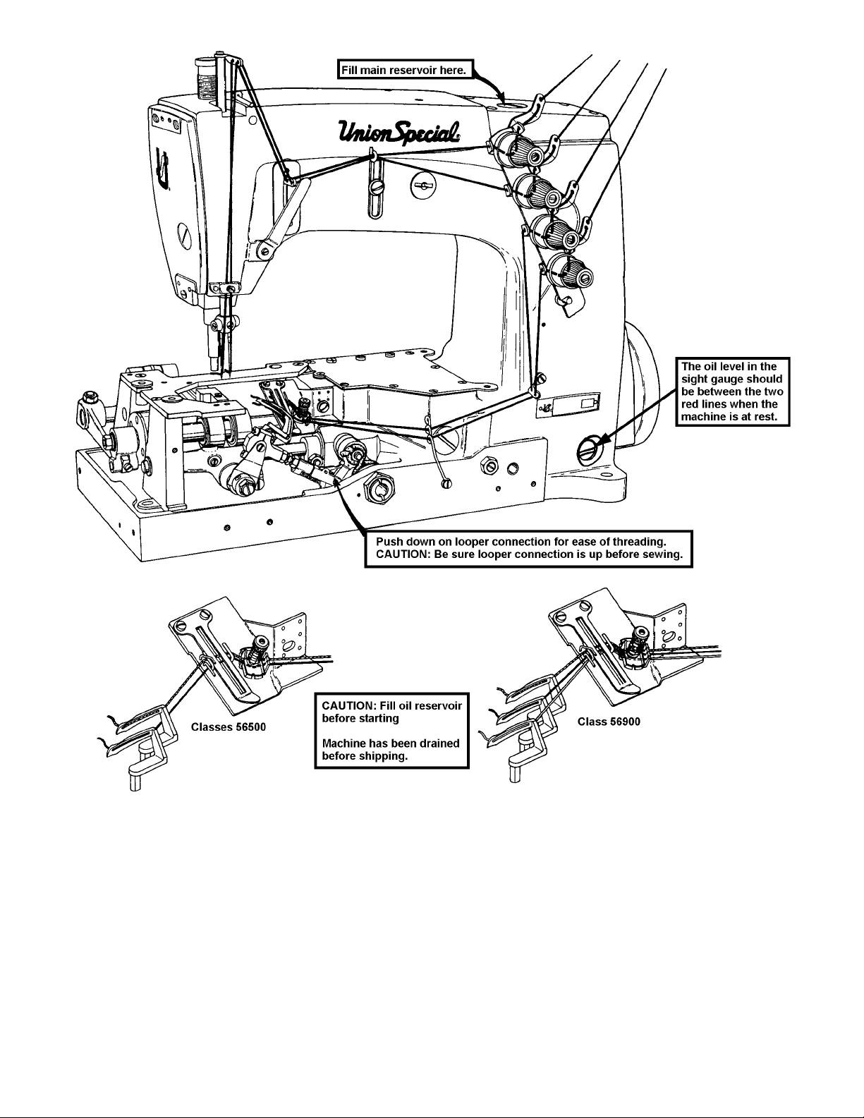
THREADING AND OILING DIAGRAM
The oil has been drained from the machine before shipping and the reservoir must be filled before
starting to operate. Maintain oil level in “OPERATE” zone; add oil when the needle on the gauge registers on the black line marked “LOW”. The machine is automatically lubricated and no oiling other than
keeping the main reservoir filled is necessary. Refer to instructions under “LUBRICATION” and “CHANGING LENGTH” for additional information.
Threading is illustrated above for all Styles.
7
Page 8
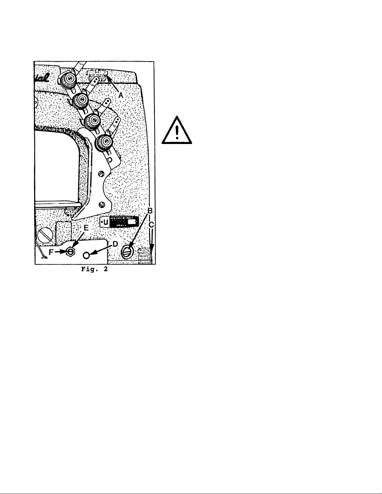
LUBRICATION
Use a straight mineral oil with a Saybolt viscosity of 90 to 125 seconds at 100 degrees Fahrenheit. This is
equivalent to Union Special Corporation Specification No. 175.
The oil should be between the two red lines in sight gauge (B)
when the machine is at rest.
1. If oil is required remove oil cap (A).
2. Fill between lines with Union Special Specification 175 oil
(Union Special Part No. 28604R).
Caution: Do not exceed the upper red marker line.
Excessive oil in machine will result in oil
leakage and possible overheating.
3. To drain oil reservoir, remove plug screw (C), on lower right
end of machine below the handwheel. Oil must be
changed every 2000 operating hours to minimize wear.
4. On new machines, or a machine out of service for an
extended period of time; lubricate machine as follows:
Remove head cover, clean out lint, then directly oil needle
bar link and needle bar. Replace head cover and fill
machine with oil to proper level. Run machine at low RPM
to ensure proper lubrication of components preventing any
damage which may occur from lack of oil distribution.
NEEDLES
Each needle has both a type and size number. The type number denotes the kind of shank, point,
length, groove, finish and other details. The size number, stamped on the needle shank, denotes largest
diameter of blade, measured midway between shank and eye. Collectively, type and size number
represent the complete symbol, which is given on the label of all needles packed and sold by UNION
SPECIAL.
To have needle orders promptly and accurately filled, an empty package, a sample needle, or the type
and size number should be forwarded. Use description on label. A complete order would read as
follows: “1000 needles, Type 147 GKS, Size 125/049”.
8
Page 9
NEEDLES (CONT.)
Type No. Description and Sizes
128 GAS Round shank, round point, short, double groove, struck groove, ball eye, spotted, chromium
plated - sizes 080/032, 090/036, 100/040, 110/044, 125/049, 140/054, 150/060, 170/067.
128 GJS Round shank, RG chain stitch point, short, double groove, struck groove, ball eye, spotted,
conical blade feature, chromium plated - sizes 090/036, 100/040, 110/044, 125/049, 140/054.
147 GKS Round shank, round point, long, double groove, struck groove, oversize ball eye, spotted,
short point, standard eye and grooves, chromium plated - sizes 090/036, 100/040, 110/044,
125/049, 140/054.
Selection of proper needle size is determined by size of the thread used. Thread should pass freely
through needle eye in order to produce a good stitch formation.
ADJUSTING INSTRUCTIONS
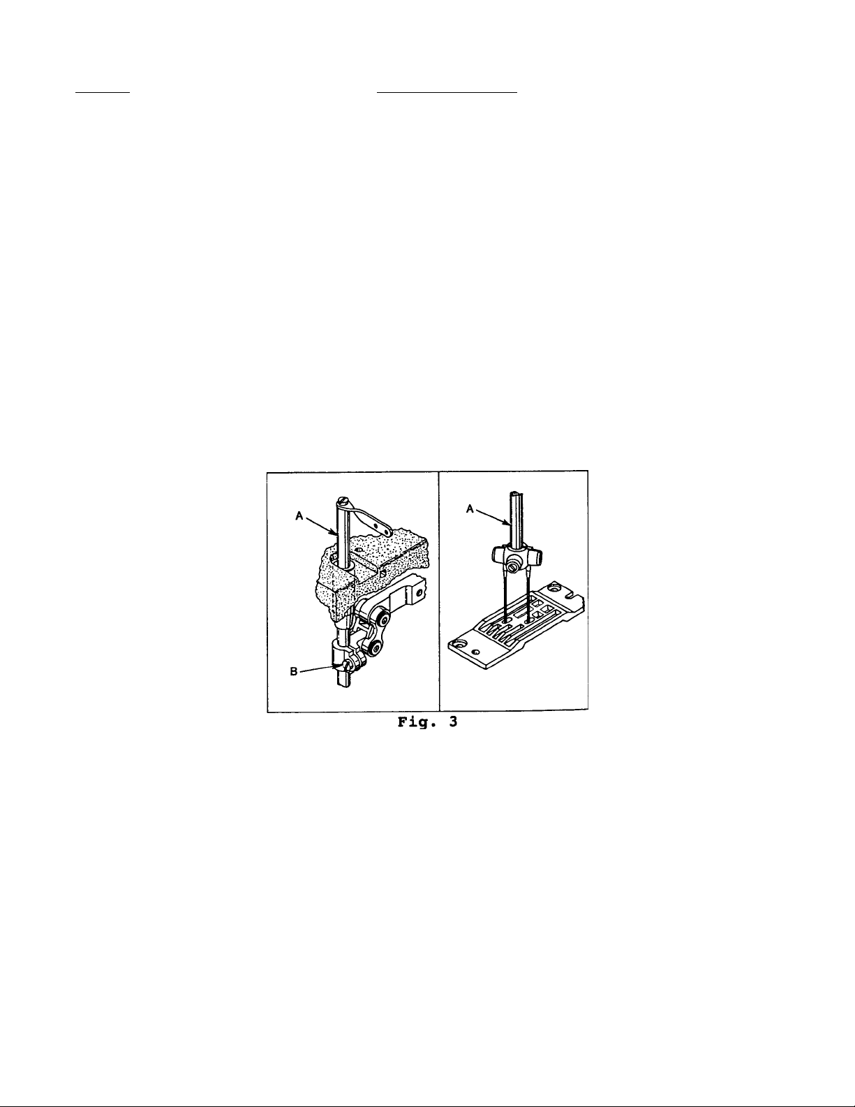
NEEDLE BAR ALIGNMENT
Insert a new set of needles (type and size required). Turn handwheel to bring needle bar (A, Fig. 3)
down to ensure that needles center in needle holes of throat plate as shown in Fig. 3. Adjustment can
be made by loosening screw (B) slightly, allowing needle bar to be turned as required. Tighten clamp
screw.
9
Page 10

SYNCHRONIZING LOOPER AND NEEDLE MOTIONS
Insert looper into the looper rocker, pushing it all the way down and tighten screw against f lat on shank
of looper. Turn handwheel in operating direction until the point of the looper (A, Fig. 4) moving to the
left, is even with the left side of the right needle (B). Note the height of the eye of the needle with
respect to the looper point (See Fig. 5) . Turn the handwheel in the reverse direction until the point of
looper, again moving to the left, is even with the left side of right needle (See Fig. 5). If the height of the
eye of the needle with respect to the looper point are the same, looper and needle motions are
synchronized. A variation of .005 inch (.127 mm) is allowable. If the distance from the eye of the needle
to the point of the looper is greater when the handwheel is turned in the operating direction, the looper
drive lever rocker shaft will have to be moved slightly towards the rear. Moving the shaft towards the
front acts the reverse.
NOTE: The 1/64 inch (.4mm) dimension shown in Fig. 5 is for final setting of needle bar height.
Adjust the looper drive rocker lever shaft as-follows:
Loosen screw (C, Fig. 4) in looper drive lever (D). A rod of .146-40 thread or Union Special Screw No.
22870A can be threaded into the looper drive lever rocker shaft through the center of thrust adjusting
screw (E). Tap or pull slightly as required to position shaft for proper synchronization. Tighten screw (C)
securely and remove rod or screw used to position shaft. Loosen lock nut (F) and torque thrust adjusting
screw (E) to 6 in. lbs. (7cm/kg); retighten lock nut (F) securely.
10
Page 11
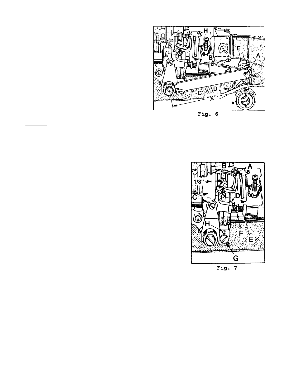
SYNCHRONIZING LOOPER AND NEEDLE MOTIONS (CONT.)
Turn handwheel in operating direction until looper is
at the extreme right end of its travel. Check location
of the center-line of right looper connecting rod
bearing using gauge TT35. Place hole in gauge (B,
Fig. 6) over threaded stud (A). The left end of gauge
should locate against the RIGHT side of looper
rocker cone (C). If adjustment is necessary, loosen
clamp screw (D), reposition looper driver lever (E) as
required and retighten screw (D). If a gauge is not
available, the setting can be checked with a scale.
"X" dimension is from centerline of stud (A) to
centerline of cone (C) which should be 4 1/16 inch
(103.2mm).
CAUTION: After adjusting the looper gauge and looper avoid, there should be shake at both end
points of the looper connecting rod while rotating handwheel a full 360o (H, Fig. 6). If bind occurrs
loosen nuts (D and E, Fig. 7) and reposition strap (H). Retighten nuts.
LOOPER SETTINGS
Insert a new needle, type and size as specified. Using the 1/8 inch
(3.2mm) looper gauge, set the looper (A, Fig. 7) so the distance from
the center of the needle (B) to the point of the looper is 1/8 inch
(3.2mm), when the looper is at its farthest position to the right.
Looper gauge No. 21225-1/8 (C) can be used advantageously in
making this adjustment. On two needle machines set the back looper
to the right needle and on three needle machines set the middle
looper to the middle needle, when setting the looper gauge. The
chart on the following page indicates needle Type, looper gauge
setting and looper gauge number. if adjustment is required, loosen
nut (D) (it has a left hand thread) and nut (E) on connecting rod (F),
turn the connecting rod forward or backward to obtain the 1/8 inch
(3.2mm) dimension. Retighten both nuts, first nut (E), then nut (D).
Make sure the left ball joint is in vertical position and does not bind
after adjustment.
11
Page 12
LOOPER SETTINGS (CONT.)
enihcaM
elytS
R00565SKG741)mm2.3(hcnI8/18/1-52212
P00965SKG741)m
R00965SKG741)mm2.3(hcnI8/18/1-52212
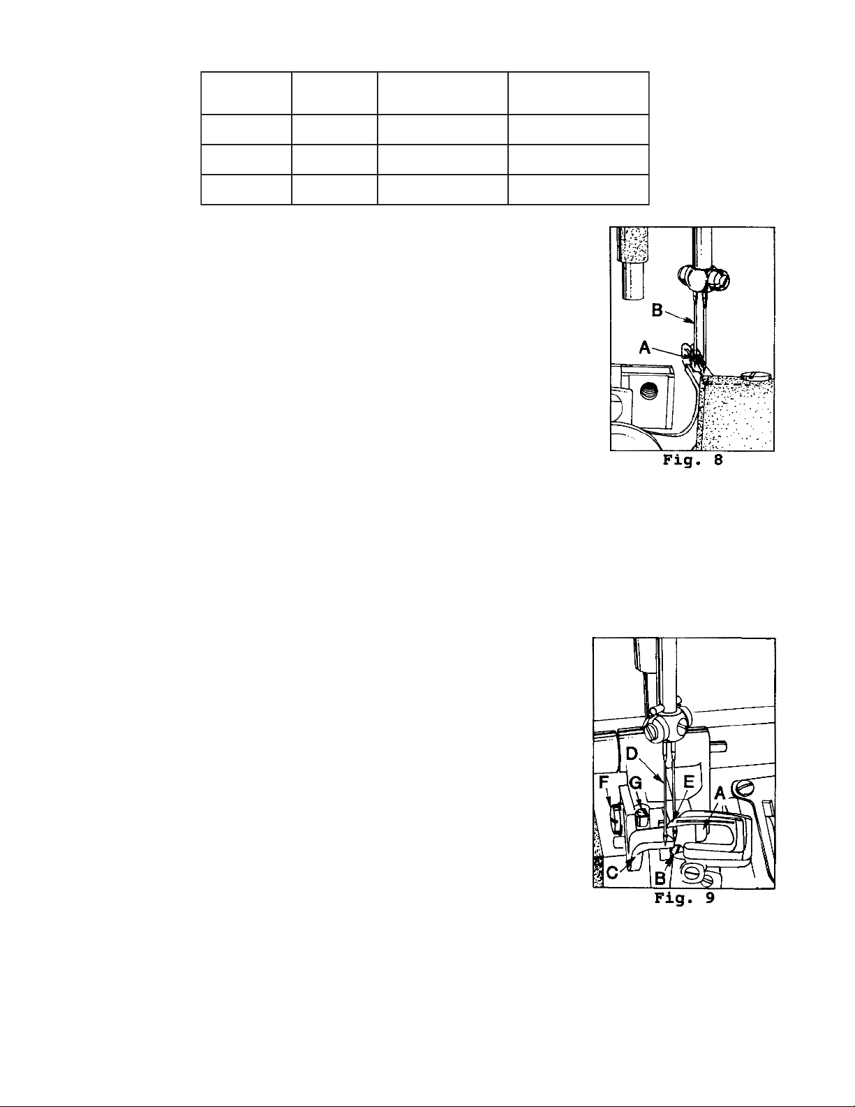
The looper is set correctly if, as it moves to the left behind the needle, its
point (A, Fig. 8) clears the rear of needle (B) by .002 inch (.051mm).
If adjustment is necessary, loosen lock screw (G, Fig. 7) and turn stop screw
(H) as required. Turning stop screw clockwise sets the looper to the rear
and turning it counterclockwise acts the reverse. Holding looper to the
front while making this adjustment may prove helpful. Tighten lock screw
when setting is obtained and recheck the adjustment.
Insert the other needles and loopers. Other than applying pressure on the
looper at the front or back Fig. 8 of the blade, so as to get the proper inline-of-feed setting, the same looper to needle relationship should exist
without any further adjustment while clamping the looper in the looper
rocker.
eldeeN
epyT
eguaGrepooL
gnitteS
m2.3(hcnI8/18/1-52212
eguaGrepooL
rebmuN
NEEDLE BAR HEIGHT
The height of the needle is correct when the top of its eye is 1/64 to 1/32 inch (.4 - .8mm) below the
underside of the looper, when the looper point flush with the left side of the needle as shown in Fig. 5. If
adjustment is necessary, loosen screw (B, Fig. 3) and move needle bar (A) up or down as required and
retighen screw. Care should be taken not to disturb alignment of needle bar when moving the needle
bar either up or down. The descending needles must be deflected alike on the back of the loopers.
REAR NEEDLE GUARD
Rotate handwheel in operating direction to position looper point at the
right hand side of needle. At this time the needle guard (C, Fig. 9) should
be at its extreme end of forward travel. Set the guard front to back to just
touch the needles, up to .002" (.05mm) deflection is permissible on one or
two needles. Guard should be set as low as possible, yet have its vertical
face approach approximately 3/64 +/- 1/64 inch (1.2mm +/- .4mm) above
the needle point. To move needle guard forward or backward, loosen the
screw (F), move needle guard as required, and retighten screw. To raise
or lower needle guard, loosen screw (F), and turn screw (G) clockwise to
lower needle guard or counterclockwise to raise it. Retighten screw (F)
after guard is properly set.
12
Page 13
REAR NEEDLE GUARD (CONT.)
NOTE: Any change in stitch length will require a change in rear needle guard setting.
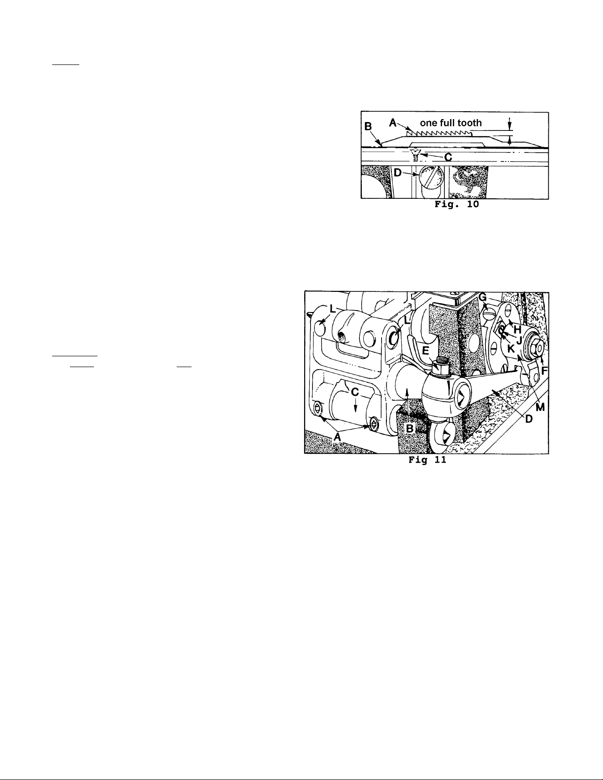
FEED DOG SETTINGS
Feed dog (A, Fig. 10) should be centered in throat plate (B)
with equal clearance on all sides and ends with feed travel set
to desired stitch length. At highest point of travel, tips of feed
dog teeth should extend the depth of one full tooth +1/32 inch,
above throat plate and parallel to same. Loosen screw (D),
which secures feed dog in position, and adjust screw (C) up or
down to support feed dog. Retighten screw (D).
Parallel adjustment can be made by loosening nut (A, Fig. 9) and turn screw (B) clockwise to lower front
of feed dog, counterclockwise acts the reverse. When properly set, retighten nut (A).
Right to left adjustment can be made by loosening screw (A, Fig. 11) and slightly move feed rocker (B)
on feed rocker shaft (C) as required, then retighten screws. Check to ensure that feed rocker arm (D)
does not bind after adjustment.
Forward or rearward centering of the feed dog
can be accomplished by loosening nut (E, Fig.
11). Move feed rocker (B) as required and retighten nut.
CAUTION: Feed crank link sub-assembly (M, Fig.
MUST have shake with NO binds at a 360°
11)
rotation of the handwheel. Nut (F) should be
torqued at 55 in. lbs. (63 cm/kg).
PRESSER BAR HEIGHT AND PRESSER FOOT
Height of presser bar (A, Fig. 13) is correct when presser foot can be removed by depressing foot lifter
lever (B, Fig. 12). There should be approximately 1/32 inch (0.8mm) clearance between the lower surface of the presser bar connection and guide (B, Fig. 13) and the bottom surface of the casting head
opening when foot lifter lever is released and the presser foot is lying flat on throat plate. Make sure
feed dog is below throat plate surface.
13
Page 14
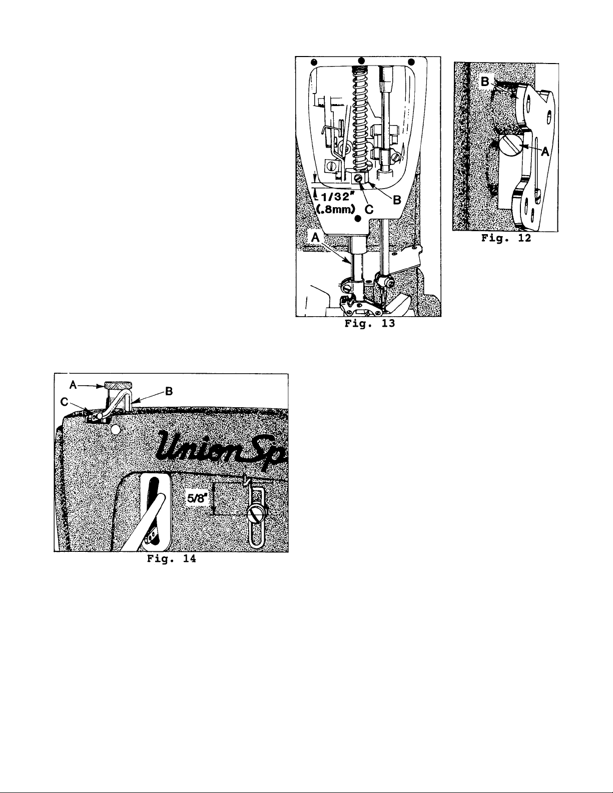
PRESSER BAR HEIGHT (CONT.)
Adjustment can be made by turning
handwheel to position needle bar at bottom
of stroke. Loosen screw (C, Fig. 13) and while
holding presser foot down on throat plate,
position presser bar connection and guide as
required to attain specified clearance and
retighten screw.
PRESSER FOOT PRESSURE
Regulate presser spring regulating screw (A,
Fig. 14) so that it exerts only enough pressure
on the presser foot to feed the work uniformly
when a slight tension is placed on the fabric.
Turning it clockwise increases the pressure
counterclockwise acts the reverse.
NEEDLE THREAD TAKE-UP WIRE AND FRAME EYELET
Set needle thread take-up wire (B, Fig. 14), so that its
upper surf ace is even with the top of the holes in
needle bar thread eyelet (C) when needle bar has
completed its downward stroke. Lower this setting
for a smaller needle thread loop, or raise it for a
larger loop. Set needle thread frame eyelet (D) so
that the eyelet hole is 5/8 inch (15.9mm) above the
attaching screw.
CHANGING STITCH LENGTH
Set the stitch to required length. This is accomplished by loosening locknut (F, Fig. 11) on the end of the
stitch regulating stud 1/2 turn (it has a left hand thread). Turn stitch adjusting screw (G) located under
the left end of the cloth plate, in the end of main shaft (H), which is marked with “L” and “S”. Turning
the screw clockwise shortens the stitch (moves stitch regulating stud toward the “S”) and turning it in a
counterclockwise direction lengthens the stitch (moves stitch regulating stud toward the "L"). Retighten
locknut securely. To prevent destructive damage to the feed drive bearing, key screw (J) must engage
the “U” shaped key slot in ferrule (K).
14
Page 15

CHANGING STITCH LENGTH (CONT.)
NOTE: Any change in stitch length will necessitate a corresponding change in the rear needle guard
setting.
Needle bearings in the feed rocker at locations (L, Fig. 11) may require repacking after years of service.
Bearings should be thoroughly cleaned and repacked with Union Special Corporation grease No.
28604P.
THREAD TENSIONS
The tension on the needle thread should be only sufficient to produce uniform stitches on the under
surface of the fabric.
The looper thread tension is applied at the cast-off support tension disc assembly, and the adjusting nut
should be set so that the tension on the looper thread is just sufficient to steady the thread.
THREAD TENSION RELEASE
The thread tension release is set correctly when it begins to function as the presser foot is raised to within
1/8 inch (3.2mm) of the end of its travel and is entirely released when the presser foot has reached its
highest position.
If adjustment is required, loosen tension release lever screw (A, Fig.12), located at the back of machine
and move tension disc separator as required. Retighten screw. After adjustment there should be no
binding at any point.
TORQUE REQUIREMENTS
Torque specifications given in this catalog are measured in inch-pounds or centimeter/kilograms. All
straps and eccentrics must be tightened to 19-21 in. lbs. (22-24cm/kg) unless otherwise noted. All nuts,
bolts, screws, etc., without torque specifications must be secured as tightly as possible, unless noted.
Special torque specifications for connecting rods, links, screws, etc., are shown on parts illustrations.
15
Page 16

SPECIAL INSTRUCTIONS
NEEDLE LEVER
When adjusting needle lever or replacing related parts, follow instructions in sequence as listed:
1. Install “O” rings (A, Fig. 15) onto needle lever stud (B) and thrust collar (C).
2. With needle lever (D) in machine and positioned properly; insert stud (B) through hole in needle lever
until its shoulder contacts the needle lever and the word “UP” on stud is in the upright position. While
making sure no binding exits in the needle bar link, secure stud (B) with the front set screw in top of
machine bed.
3. Install temper load ring (E) and compression cups (F) onto stud (B), then push ring and cups through
opening in machine bed.
4. Install thrust collar (C) onto stud (B) being careful not to damage “O” ring. Compress components
together by tightening screw (G)until washer (H) bottoms against stud (B). Secure stud (B) in position
using the rear set screw in top of bed.
5. To check temper load ring for proper compression, remove screw (G) f rom stud (B) and loosen rear
set screw in top of bed. Thrust collar (C) should spring out .003 -.007 inch (. 08-.18mm) . Compress
load ring in reverse order, then tighten rear set screw.
6. With indented “UP” on stud (B) in upright position, install bearing oiler (J) so it’s hook sets in oil supply
hole (K) of stud. When hook and stud are secured in their proper position, the proper amount of oil
will be channeled to stud for lubricating needle lever (D).
16
Page 17
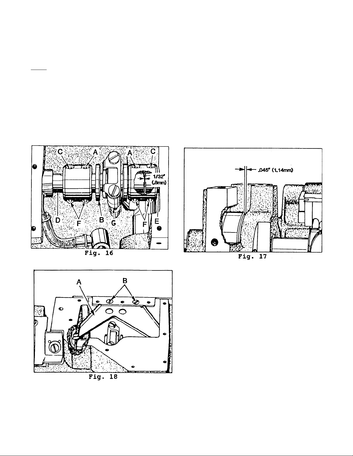
ALIGNING MAINSHAFT TO CRANKSHAFT
As viewed looking down from rear of machine, spot screw (A, Fig. 16) in the couplings must align with
the spots in the looper drive crank (B) and set screws (C) must align with the flats on crankshaft (D) and
mainshaft (E). Mainshaft must be positioned laterally with .045 inch (1.14nun) clearance between the
right side of its head and the bed casting as shown (Fig. 17).
NOTE: Recheck to make sure that the take-up cam is centered in the cast-off plate without rubbing
either side.
Looper drive crank (B, Fig. 16) must be positioned laterally so that strap (G, Fig. 16) is vertical and 1/32
inch clearance is maintained between end of crank and end of mainshaft (E) as shown. Once these
settings are made, it is very important that the couplings are tightened in the following sequence for
best performance.
Snug spot screws (A) temporarily, to the looper drive crank. Snug set screws (C) temporarily, to the
crankshaft and mainshaft. Torque screws (F) to 19-21 in. lbs. (22-24cm/kg). Loosen spot screws (A) and
set screws (C). Re-torque screws (F) to 19-21 in. lbs. (22-24cm/kg), then, torque screws (A and C) to 1921 in. lbs. (22-24cm/kg).
The oil drip plate (A, Fig. 18) located in the oil
reservoir should be positioned with its tip in the
recessed cut out in the bed casting, as far to the
left as possible without touching. It has elongated
mounting holes and can be adjusted by loosening (2) screws (B)in top of the oil reservoir back
cover to position as required, retighten screws.
17
Page 18

ORDERING REPAIR PARTS
ILLUSTRATIONS
This catalog has been arranged to simplify ordering repair parts. Exploded views of various sections of
the mechanism are shown so that the parts may be seen in their actual position in the machine. On the
page opposite the illustration will be found a listing of the parts with their part numbers, descriptions and
the numbers of pieces required in the particular view being shown.
Numbers in the first column are reference numbers only and merely indicate the position of that part in
the illustration. Reference numbers should never be used in ordering parts. Always use the part number
listed in the second column.
Component parts of sub-assemblies which can be furnished for repairs are indicated by indenting their
descriptions under the description of the main sub-assembly. Example:
9. 29105AK Looper Drive Lever Crank Assembly, for all Styles ......................................... 1
10. 22559A Bearing Cap Screw, lower ................................................................. 2
11. 56343E Oil Splasher ........................................................................................ 1
12. 56343C Ball Joint Guide Fork .......................................................................... 1
13. 22587K Bearing Cap Screw, upper ................................................................ 1
It will be noted in the above example that the eccentric ball stud and bearing are not listed. The reason
is that replacement of these parts individually is not recommended, so the complete sub-assembly
should be ordered.
IDENTIFYING PARTS
Where the construction permits, each part is stamped with its part number. On some of the smaller parts
and on those where construction does not permit, an identification letter is stamped in to distinguish the
part from similar ones.
PLEASE NOTE: Part numbers represent the same part, regardless of which catalog they appear. On all
orders, please include part name and style of machine for which part is ordered.
TERMS
Prices are net cash and subject to change without notice. All shipments are forwarded f.o.b. shipping
point. Parcel Post shipments are insured unless otherwise directed. A charge is made to cover postage
and insurance.
18
Page 19

Before this machine left the factory it was adjusted and inspected to give you the utmost satisfaction
and durability at all times. if, however, the machine is not sewing properly, see chart below for suggestions which may prove beneficial to you.
SKIPPED STITCHES
noitidnoCsesuaCseruC
.llamsootpooleldeeN.wolootteseriwpu-ekaTylthgilseriwpu-ekatesiaR
hteldeeN
.deveilerdehcterts
loc,draug
.taehoteudsevoorg
sapooleldeensessimrepooL
ronognimocsitoofresserp
.maesehtffognimoc
ylreporpdemrofpooleldeeN
tuodehsurbtub
.repool
ybyawehtfo
.ylreporppooleldeenmrof
fninwoddlehtonsilairetaM
mottobtadehctertsdaer
llitdemroftonpool-ekortsfo
.ylreporpdedaerhttonsienihcaM.margaidgnidaerhtrof8egapeeS
eldeenybdehcnipdaerhteldeeN
.pooleldeengnispal
.eldeendnuoragnitsiwtdaerhT elbissopsallamssapooleldeenpeeK
eldeennignikcitsdaerhteldeeN
esuacebdesaercdaerhteldeeN
.eyeeldeenrofgibootsidaerht
othguoneesirtonseodeldeeN
rotnor
.gniggalfsidnamaesfokcab
.rotarepodrawotgnitcelfedeldeeN.SAG821eldeentniopprahsesU
.wolootrohgihoottesrabeldeeN.snoitacificepsotrabeldeenteS
.noisneteldeen
.ylthgilsdraugeldeenporD
tnoisnetdaerhteldeendna
.daerhttsiwttfelaesU
neyellabezisrevoesU
.noitcirfecuder
ldeenroeldeenregralesU
.sevoorgdnaeye
eguagrepoolteseR
.snoitacificeps
esserpfiees
.gnikcitssirabr
decuderro/dnateleyedaerhtemarfrewoL
.muminimao
otSKG741eldee
dezisrevohtiwe
otthgieheldeendna
roelbaliavafitoofresserpepytrotcartesU
pooleldeensessimrepooL
niyrtsirotareponehw
otg
fosdnerosmaeshctam
.stnemrag
pooleldeensessimenihcaM
sihtgnelhctitsnehw
ercni
.desa
noelgnairtsessimeldeeN
.edisdaerhtrepool
.maes
.stnemragfosdne
.drawrofrafoottessi
.elgnairtdoogagnikam
rotarepodrawotgnitcelfedeldeeN
nokcabgnidlohebyamohw
aesgnihctamelihwlairetam
rosm
ehtdrawotgnitcelfedeldeeN
ton-esoolootdaerhtrepooL
eldeenro,tniopeldeennorrubyb
anognimocnehwffognicnalg
orP
.kcabdlohtonseod
oM
draugeldeenehtesuacebrotarepo
poolesaercnI
raerehtotdetcelfedgniebeldeeN
.raerehtotdraugeldeenev
.noisnetdaerhtre
.lairetamnoylevissecxekcabdlohtonoD
aniatniamdnadeeftsujdaylrep
retarepooserusserptoofresserpmrofinu
feldeenpotsoteldeenprahsaesU
mor
.rrubrofeldeenkcehC.maesffognicnalg
19
Page 20

20
Page 21

EXPLODED VIEWS
AND
DESCRIPTION OF PARTS
21
Page 22

22
Page 23

MAIN FRAME, THROAT PLATE SUPPORT, MISC. COVERS & OILING PARTS
Ref.
No.
1.
2.
3.
4.
5.
6.
7.
8.
9.
10.
11.
12.
13.
14.
15.
16.
17.
18.
19.
20.
21.
22.
23.
24.
25.
26.
27.
28.
29.
30.
31.
32.
33.
34.
35.
36.
37.
38.
39.
40.
41.
Part No.
56480
51280J
660-313
22570
22839
22585A
22524
56382AW
56382H
56382AA
56382AB
56382Y
56382AX
56382D
22548
56382AU
22848
22829
56382J
56382AV
22585A
33795
59493A
666-214
258A
666-230
22894E
56470
95
35731A
660-342
51294R
56393C
7947
56393D
56382AT
56382B
22733C
22569C
22585
22513
Description
Throat Plate Support ...................................................................................
Dowel Pin ..............................................................................................
Well Nut .......................................................................................................
Screw, for throat plate ................................................................................
Screw, for throat plate support ...................................................................
Screw ..........................................................................................................
Screw, for ref. no. 8 and 12 ..........................................................................
Oil Reservoir Cover, top ..............................................................................
Gasket ........................................................................................................
Oil Reservoir Cover, back ............................................................................
Oil Drip Plate ...............................................................................................
Oil Drip Plate Clamping Block .....................................................................
Gasket ........................................................................................................
Crank Chamber Cover, lower .....................................................................
Screw ..........................................................................................................
Gasket ........................................................................................................
Screw ..........................................................................................................
Screw ..........................................................................................................
Looper Drive Shaft Reservoir Cover ............................................................
Gasket ........................................................................................................
Screw, for needle bar ..................................................................................
Needle Bar Eyelet Guard ............................................................................
Base Oil Pump Assembly .............................................................................
Intake Felt .............................................................................................
Nut, for ref. no. 22 ........................................................................................
Gasket, for ref. no. 22 ..................................................................................
Screw, for ref. no. 10, 42 on page 29 ............................................................
Needle Thread Take-up Wire .......................................................................
Plug Screw ..................................................................................................
Presser Bar Connection Guide Plate ...........................................................
Lockwasher ................................................................................................
Screw, for ref. no. 29 ....................................................................................
Head Oil Tube Mounting Block ....................................................................
Nut ..............................................................................................................
Head Oil Tube Clamp ..................................................................................
Gasket, for head cover ...............................................................................
Head Cover, all Styles .................................................................................
Plug Screw ............................................................................................
Screw, for head cover .................................................................................
Screw, for head oil tube mounting bracket .................................................
Screw, for ref. no. 30 ....................................................................................
Amt.
Req.
1
2
3
2
3
3
10
1
1
1
1
1
1
1
4
1
9
2
1
1
1
1
1
1
1
1
2
1
1
2
1
1
1
1
1
1
1
1
3
1
3
42. thru 72 See following page.
23
Page 24

24
Page 25

MAIN FRAME, THROAT PLATE SUPPORT, MISC. COVERS & OILING PARTS (CONT.)
Ref.
No.
Part No.
1. thru 41. See preceding page.
42.
43296
43.
605A
44.
57WB
45.
15438C
46.
57WD
47.
56958B
48.
99680
49.
96120
50.
22517C
51.
660-617
52.
539
53.
22889A
54.
20
55.
22848
56.
21375CA
57.
22829
58.
98A
59.
158B
60.
158A
61.
56391A
62.
52958G
63.
21396BR
64.
660-73
65.
21396AL
66.
660-75
67.
660-74
68.
11638M
69.
22569C
70.
21396BP
71.
21396AG
72.
21396BK
Description
Base, nipper spring ......................................................................................
Screw ...........................................................................................................
Nipper Spring Plate ......................................................................................
Spring ...........................................................................................................
Screw, nipper spring ....................................................................................
Eyelet ...........................................................................................................
Needle Lever Eyelet Guard ..........................................................................
Lockwasher .................................................................................................
Screw, for needle lever eyelet guard ...........................................................
Needle Lever Eyelet Gasket ........................................................................
Frame Needle Thread Eyelet .......................................................................
Adapter Plug Screw .....................................................................................
Washer .........................................................................................................
Screw, for frame needle thread eyelet ........................................................
Belt Guard ....................................................................................................
Screw, for belt guard ...................................................................................
Screw, for looper thread guard and eyelet .................................................
Looper Thread Eyelet, for Class 56500 ..........................................................
Looper Thread Eyelet, for Class 56900 ..........................................................
Looper Thread Guard ..................................................................................
Looper Thread Eyelet ...................................................................................
Needle Thread Lubricator Oil Reservoir .......................................................
Oil Cup ..................................................................................................
Adapter .................................................................................................
Coupling ...............................................................................................
Connecting Sleeve ...............................................................................
Nut .........................................................................................................
Screw, for thread lubricator .........................................................................
Needle Thread Lubricator ............................................................................
Felt Pad ..................................................................................................
Needle Thread Lubricator Oil Reservoir Bracket ..........................................
Amt.
Req.
1
1
1
1
1
1
1
1
1
1
1
1
1
1
1
2
3
1
1
1
1
1
1
1
1
1
1
2
1
2
1
25
Page 26

26
Page 27

MAIN FRAME, BUSHINGS, OIL GAUGE & LOOPER DRIVING PARTS
Ref.
No.
1.
2.
3.
4.
5.
6.
7.
8.
9.
10.
11.
12.
13.
14.
15.
16.
17.
18.
19.
20.
21.
22.
23.
24.
25.
26.
27.
28.
29.
30.
31.
32.
33.
34.
Part No.
660-1002
22541C
56382AM
56382AY
90
56382AC
56390H
56390J
660-665
22569B
57890B
56390E
21657X
22539R
51-902BLK
56342D
52942AC
35897BV
56393Q
56390G
51154E
56393W
57836B
666-259
56390
50-895BLK
56393P
52942W
56190
57842B
57954
51257AA
GR-56393T
56393L
Description
Oil Filter Plug Screw .....................................................................................
Screw, for chamber cover ..........................................................................
Upper Crank Chamber Cover ....................................................................
Gasket, for chamber cover ........................................................................
Screw, for oiler and baffle plate assembly ..................................................
Needle Lever Bearing Oiler and Baffle Plate Assembly ...............................
Thrust Washer ..............................................................................................
Pilot Ring .....................................................................................................
Needle Thrust Bearing .................................................................................
Screw, for crankshaft bushing housing .......................................................
Crankshaft Bushing Housing .......................................................................
Gasket, for bushing housing .......................................................................
Tension Release Lever Shaft Bushing ...........................................................
Plug Screw ..................................................................................................
Oil Sight Gauge ...........................................................................................
Nut, for thrust adjusting screw .....................................................................
Thrust Adjusting Screw ................................................................................
Oil Intake Filter ............................................................................................
Base Felt, rear .............................................................................................
Main Shaft Bushing, right .............................................................................
Needle Bar Bushing, upper .........................................................................
Oil Attraction Felt ........................................................................................
Feed Rocker Shaft Bushing .........................................................................
Felt ..............................................................................................................
Main Shaft Bushing, left ...............................................................................
Looper Rocker Shaft Bushing ......................................................................
Base Felt, front ............................................................................................
Looper Drive Lever Shaft Bushing, front ......................................................
Main Shaft Bushing, intermediate ...............................................................
Looper Drive Lever Shaft Bushing, rear .......................................................
Needle Bar Bushing, lower ..........................................................................
Presser Bar Bushing, lower ...........................................................................
Head Oil Pump Assembly ............................................................................
Intake Felt .............................................................................................
Amt.
Req.
1
4
1
1
2
1
4
2
2
3
1
1
1
2
1
1
1
1
1
1
1
1
2
1
1
2
1
1
1
1
1
1
1
1
27
Page 28

28
Page 29

CRANKSHAFT, NEEDLE LEVER & LOOPER DRIVING PARTS
Ref.
No.
1.
2.
3.
4.
5.
6.
7.
8.
9.
10.
11.
12.
13.
14.
15.
16.
17.
18.
19.
20.
21.
22.
23.
24.
25.
26.
27.
28.
29.
30.
31.
32.
33.
34.
35.
36.
37.
38.
39.
40.
41.
42.
Part No.
27-435BLK
56458A
22804
56958A
22586R
GR-51250V
51250D
56382AK
660-625
56350E
56350F
660-614
29066R
22559G
51216N
51216P
56321R
22894AB
57821A
61321L
22574
660-202
57847
95
51247
22894J
56316
56458
22768
56958
29348AF
22564
51254K
22562A
52336
WO3
660-215
56354D
77
56315A
56350G
56350D
Description
Needle Bar Eyelet Washer ..........................................................................
Needle Bar Thread Eyelet, for Class 56500 ..................................................
Screw ..........................................................................................................
Needle Bar Thread Eyelet, for Class 56900 ..................................................
Screw ..........................................................................................................
Gasket ........................................................................................................
Washer .......................................................................................................
Gasket ........................................................................................................
Oil Seal Ring ................................................................................................
Needle Lever Thrust Collar ..........................................................................
Compression Cup .......................................................................................
Temper Load Ring .......................................................................................
Needle Lever Connecting Rod Upper Ball Joint Assembly ..........................
Screw ...................................................................................................
Washer .......................................................................................................
Nut ..............................................................................................................
Pulley ..........................................................................................................
Screw ...................................................................................................
Handwheel .................................................................................................
Retaining Plate ...........................................................................................
Screw ..........................................................................................................
"O" Ring, for pulley and looper drive lever rocker shaft ...............................
Thrust Collar ................................................................................................
Screw ...................................................................................................
Counterweight ...........................................................................................
Screw ...................................................................................................
Needle Lever Connecting Rod ...................................................................
Needle Lever Thread Eyelet, for Class 56500 ...............................................
Screw ..........................................................................................................
Needle Lever Thread Eyelet, for Class 56900 ...............................................
Needle Lever Assembly ..............................................................................
Screw ...................................................................................................
Needle Bar Connection .......................................................................
Screw .............................................................................................
Link Pin ..................................................................................................
Yarn (6 Strands) ..............................................................................
Retaining Ring ......................................................................................
Needle Bar Link .....................................................................................
Screw ...................................................................................................
Needle Lever ........................................................................................
Bushing ..........................................................................................
Needle Lever Stud ................................................................................
Amt.
Req.
1
1
1
1
1
1
1
1
2
1
2
1
1
2
1
1
1
2
1
1
4
2
1
2
1
2
2
1
1
1
1
1
1
1
2
4
1
1
1
1
1
43. thru 64. See following page.
29
Page 30

30
Page 31

CRANKSHAFT, NEEDLE LEVER & LOOPER DRIVING PARTS CONT.
Ref.
No.
Part No.
1. thru 42. See preceding page.
43.
29476LN
44.
51216M
45.
56316C
46.
12934A
47.
48.
49.
22894C
50.
22894D
51.
56343F
52.
22653L8
53.
29105AK
54.
22587K
55.
56343C
56.
56343E
57.
22559A
58.
52942AA
59.
CL21
60.
52942AC
61.
56342G
62.
56390H
63.
660-665
64.
56390J
Description
Crankshaft Assembly ..................................................................................
Needle Bearing ....................................................................................
Connecting Rod Guide ...............................................................................
Nut ..............................................................................................................
Head Oil Pump, ref. no. 44 on page 27 ........................................................
Base Oil Pump, ref. no. 23 on page 23 .........................................................
Set Screw ....................................................................................................
Spot Screw ..................................................................................................
Looper Drive Lever Coupling ......................................................................
Screw ....................................................................................................
Looper Drive Lever Crank Assembly ............................................................
Bearing Cap Screw, upper ...................................................................
Ball Joint Guide Fork ..............................................................................
Oil Splasher ...........................................................................................
Bearing Cap Screw, lower ....................................................................
Looper Drive Lever Rocker Shaft .................................................................
Oil Wick .......................................................................................................
Thrust Adjusting Screw .................................................................................
Looper Drive Lever ......................................................................................
Thrust Washer ..............................................................................................
Needle Thrust Bearing .................................................................................
Pilot Ring .....................................................................................................
Amt.
Req.
1
28
1
2
1
1
2
2
2
2
1
2
1
1
2
1
1
1
1
4
2
2
31
Page 32

32
Page 33

LOOPER ROCKER & CONNECTING ROD PARTS
Ref.
No.
1.
2.
3.
4.
5.
6.
7.
8.
9.
10.
11.
12.
13.
14.
15.
16.
17.
18.
19.
20.
21.
22.
23.
24.
25.
26.
27.
28.
29.
30.
31.
32.
33.
33A.
34.
35.
36.
37.
38.
Part No.
CO67E
WO3
55244G
51244N
51244L
18
51216N
56344
627
56342K
22882C
51242M
20
56341N
18
51240D
269
57841
22729C
18
56344B
51236J
56344C
719
98
51246
96
22874
56393J
87U
73
22565
15465F
88
51745
258A
22829
Description
Cork Plug ....................................................................................................
Yarn (4 strands - 8 inches long) ....................................................................
Looper Rocker Shaft Collar Stud .................................................................
Looper Rocker Shaft Clamp ........................................................................
Thrust Washer ..............................................................................................
Nut ..............................................................................................................
Washer .......................................................................................................
Looper Rocker Shaft ...................................................................................
Looper Lever Stud .......................................................................................
Looper Drive Lever .....................................................................................
Screw ...................................................................................................
Washer .................................................................................................
Washer .......................................................................................................
Looper Connecting Rod Jointed Section Assembly, right ...........................
Nut, right hand thread ................................................................................
Looper Connecting Rod .............................................................................
Nut, left hand thread ..................................................................................
Looper Connecting Rod Ball Joint, left .......................................................
Screw ...................................................................................................
Looper (see page 39) .................................................................................
Nut ..............................................................................................................
Looper Rocker Shaft Arm ............................................................................
Looper Avoid Link Pin ..................................................................................
Looper Rocker Frame .................................................................................
Stop Screw ...........................................................................................
Screw ...................................................................................................
Looper Rocker Stud Nut ..............................................................................
Screw ..........................................................................................................
Looper Rocker Frame Lock Screw ..............................................................
Looper Connecting Rod Ball Joint Oiler, left..............................................
Screw..............................................................................................................
Looper Rocker Assembly (see chart below) ...............................................
Screw, for Class 56500 ..........................................................................
Screw, for Class 56900 ..........................................................................
Cone, Looper Rocker.............................................................................
Screw .............................................................................................
Stud, Looper Cone...................................................................................
Lock Nut ................................................................................................
Lock Nut Screw.....................................................................................
Amt.
Req.
1
1
1
2
1
1
1
1
1
1
1
1
1
1
1
1
1
2
1
1
1
1
1
1
1
1
1
1
1
2
3
1
2
1
1
1
.feR
.oN
23.oN.feR
ylbmessA
enihcaM
ssalC
.tmA
.qeR
A23AA29192005651
B23FA29192009651
33
Page 34

34
Page 35

MAIN SHAFT, TAKE-UPS & FEED DRIVING PARTS
Ref.
No.
1.
2.
3.
4.
5.
6.
7.
8.
9.
10.
11.
12.
13.
14.
15.
16.
17.
18.
19.
20.
21.
22.
23.
24.
25.
26.
27.
28.
29.
30.
31.
32.
33.
34.
35.
36.
37.
38.
Part No.
660-359
56335B
22651CD4
56334B
56335L
56335D
98
41391
660-438
61341J
22834A
56334N
22651CB4
22637P24
258A
6042A
22863C
56334L
51236J
22528
22801
22875H
61434G
56122A
56322B
22891B
29476NM096
22894AA
77
39543N
56323
22580D
22764C
29476NM072
77
22894AA
Description
Bearing, for feed rocker ..............................................................................
Feed Rocker ...............................................................................................
Screw, for feed bar shaft ......................................................................
Feed Bar Shaft ............................................................................................
Feed Rocker Shaft ......................................................................................
Collar, for feed rocker shaft ........................................................................
Screw ...................................................................................................
Washer .......................................................................................................
Retaining Ring ............................................................................................
Feed Bar Washer .........................................................................................
Needle Guard Adjusting Screw ..................................................................
Feed Bar .....................................................................................................
Screw ...................................................................................................
Feed Dog Height Adjusting Screw ........................................................
Nut ........................................................................................................
Washer, for feed dog holder ................................................................
Feed Dog Holder Adjusting Screw ........................................................
Feed Dog Holder ..................................................................................
Link Pin ........................................................................................................
Feed Dog (see page 47, 49) ........................................................................
Screw, for feed dog ....................................................................................
Needle Guard (see page 39) ......................................................................
Screw ...................................................................................................
Screw, for needle guard .............................................................................
Washer, for needle guard screw .................................................................
Main Shaft ..................................................................................................
Gasket ..................................................................................................
Oil Flow Regulating Screw ....................................................................
Feed Lift Eccentric Assembly, for all Styles ..................................................
Spot Screw ...........................................................................................
Screw, for link pin ..................................................................................
Thrust Washer, for feed bar .........................................................................
Looper Thread Take-up ..............................................................................
Set Screw ..............................................................................................
Spot Screw ...........................................................................................
Looper Avoid Eccentric Assembly, for all Styles ..........................................
Screw, for link pin ..................................................................................
Spot Screw ...........................................................................................
Amt.
Req.
2
1
2
1
1
1
2
1
1
2
1
1
1
1
1
1
1
1
1
1
1
1
1
1
1
1
1
1
1
1
1
2
1
1
1
1
1
1
39. thru 56. See following page.
35
Page 36

36
Page 37

MAIN SHAFT, TAKE-UPS & FEED DRIVING PARTS CONT.
Ref.
No.
Part No.
1. thru 38. See preceding page.
39.
56336D
40.
660-269B
41.
22543A
42.
56336
43.
22798C
44.
56322C
45.
22525A
46.
56335S
47.
55235E
48.
6042A
49.
55235D
50.
77
51.
56336K
52.
56336C
53.
51054
54.
666-149
55.
269
56.
21657E
Description
Feed Crank Stud Insert ................................................................................
Quad Ring ..................................................................................................
Stitch Regulating Screw ..............................................................................
Feed Crank Stud .........................................................................................
Screw ..........................................................................................................
Main Shaft Head Plate ................................................................................
Screw ..........................................................................................................
Feed Rocker Arm and Feed Crank Link Sub-Assembly ................................
Nut ........................................................................................................
Washer .................................................................................................
Locking Stud .........................................................................................
Screw, for link pin ..................................................................................
Feed Crank Link ....................................................................................
Feed Crank Link Ferrule ..................................................................
Feed Crank Link Pin ...............................................................................
Oil Wick ..........................................................................................
Nut, left thread ...........................................................................................
Washer .......................................................................................................
Amt.
Req.
1
1
1
1
1
1
4
1
1
1
1
1
1
1
1
1
1
1
37
Page 38

38
Page 39

NEEDLE BARS, HOLDERS & GUARDS, LOOPERS & LOOPER THREAD TAKE-UP PARTS
Ref.
No.
1.
2.
3.
4.
5.
6.
7.
8.
9.
10.
11.
12.
13.
14.
15.
16.
17.
18.
19.
20.
21.
22.
23.
24.
25.
26.
27.
28.
29.
30.
31.
32.
33.
34.
35.
36.
Part No.
56517B16
50J16
51418-16
98
89
56525
22801
7018E5
187B
7040-6
56517B18
50J16
56917
50J26
35818N8
-
C50018B9
22580
22752
56925
22801
51508M16
51508M18
51908B8
51908B9
51909C
51909D8
51909D9
51959D
51959K
51959B
51492
51459A
51959J
22528
21657E
51457A
50-216BLK
52804A
28
Description
Needle Bar, for Style 56500R16 .....................................................................
Stop Pin ..................................................................................................
Needle Holder, for Style 56500R16 ...............................................................
Screw, for needle .........................................................................................
Spot Screw ...................................................................................................
Needle Guard, for Class 56500, all gauges ..................................................
Screw ....................................................................................................
Needle Holder, for Style 56500R18 ...............................................................
Screw ....................................................................................................
Thread Guide ........................................................................................
Needle Bar, for Style 56500R18 .....................................................................
Stop Pin ..................................................................................................
Needle Bar, for Class 56900, all gauges ........................................................
Stop Pin ..................................................................................................
Needle Holder, for Styles 56900P8, R8 ..........................................................
Needle Holder, for Styles 56900P9, R9 ..........................................................
Screw, for needle .........................................................................................
Screw, for center needle .............................................................................
Needle Guard, for Class 56900, all gauges ..................................................
Screw ....................................................................................................
Looper, front, for Style 56500R16 ..................................................................
Looper, front, for Style 56500R18 ..................................................................
Looper, front, for Style 56900P8, R8 ..............................................................
Looper, front, for Style 56900P9, R9 ..............................................................
Looper, Middle, for Class 56900 and back looper for Class 56500 ................
Looper, back, for Style 56900P8, R8 ..............................................................
Looper, back, for Style 56900P9, R9 ..............................................................
Tension Nut ..................................................................................................
Tension Spring ..............................................................................................
Tension Disc .................................................................................................
Tension Post .................................................................................................
Looper Thread Guide, for Class 56500 ..........................................................
Looper Thread Guide, for Class 56900 ..........................................................
Screw ...........................................................................................................
Washer .........................................................................................................
Take-up Shield .............................................................................................
Dowel Pin .....................................................................................................
Cast-off Plate ...............................................................................................
Screw ...........................................................................................................
Amt.
Req.
1
1
1
2
1
1
1
1
1
1
1
1
1
1
1
1
2
1
1
1
1
1
1
1
1
1
1
1
1
2
1
1
1
1
1
1
2
1
2
39
Page 40

40
Page 41

DISC THREAD TENSION PARTS
Ref.
No.
1.
2.
3.
4.
5.
6.
7.
8.
9.
10.
11.
12.
13.
14.
15.
16.
17.
18.
Part No.
43266
51491C
51292D
51292A
56392E
109
56392F
51292F8
39592AK
39592Z
51292F2
22598C
80557
56382X
21657-4
51992A
59292
59292A
Description
Nut ..............................................................................................................
Lead-in Guide .............................................................................................
Tension Thread Eyelet .................................................................................
Ferrule .........................................................................................................
Tension Post ................................................................................................
Tension Disc ................................................................................................
Tension Spring Shield ...................................................................................
Needle Thread Tension Spring .....................................................................
Tension Spring Ferrule .................................................................................
Tension Nut .................................................................................................
Looper Thread Tension Spring .....................................................................
Screw ..........................................................................................................
Washer ........................................................................................................
Tension Post Support, for Class 56500 ..........................................................
Tension Disc Separator, for all Styles ............................................................
Tension Post Support, for Class 56900 ..........................................................
Auxiliary Tension Post Support, for al Styles ..................................................
Felt Washer, for auxilary tension post support .............................................
Amt. Req.
Per Style
Two
Needle
2
4
4
4
4
8
4
2
4
4
2
1
1
1
as required
Three
Needle
5
6
6
6
6
12
6
3
6
6
3
1
2
1
1
1
41
Page 42

42
Page 43

TENSION & LIFTER LEVER PARTS
Ref.
No.
1.
2.
3.
4.
5.
6.
7.
8.
9.
10.
11.
12.
13.
14.
15.
16.
17.
18.
19.
20.
Part No.
21657W
21657Y
22569
402
51283H
660-207
53783N
22537
56383AB
56383AA
56383D
22557G
22758C
402
51257M
51957E
22569F
53787
56383A
56356
Description
Tension Release and Lifter Lever Shaft ........................................................
Tension Release and Lifter Lever Shaft Connection ....................................
Screw ....................................................................................................
Screw ....................................................................................................
Lifter Lever ..................................................................................................
Oil Seal Ring ................................................................................................
Lifter Lever Connection ..............................................................................
Screw ....................................................................................................
Lifter Lever Connecting Rod .......................................................................
Lifter Lever Bell Crank ..................................................................................
Lifter Lever Bell Crank Spring .......................................................................
Screw ..........................................................................................................
Screw ..........................................................................................................
Screw ..........................................................................................................
Presser Bar Connection and Guide .............................................................
Presser Bar ...................................................................................................
Screw ..........................................................................................................
Presser Spring ..............................................................................................
Lifter Lever Link ............................................................................................
Presser Spring Regulator .............................................................................
Amt.
Req.
1
1
1
1
1
1
1
1
1
1
1
1
1
1
1
1
1
1
1
1
43
Page 44

44
Page 45

CLOTH PLATE, CLOTH PLATE COVER, FOLDER & OIL SHIELD PARTS
Ref.
No.
1.
2.
3.
4.
5.
6.
7.
8.
9.
10.
11.
12.
13.
14.
15.
16.
17.
18.
19.
Part No.
56381-207A
51281AC
35772H
22760A
22845B
25C
23425V
22848
G51381BD
G51382BA
99295
G51381BA
52978Z
51282AJ
25S
22839C
56401C
22526C
Description
Cloth Plate Cover ........................................................................................
Cloth Plate Cover Spring .......................................................................
Spring Washer .......................................................................................
Screw, for spring washer .......................................................................
Screw ....................................................................................................
Screw, for washer plate ...............................................................................
Washer Plate ...............................................................................................
Double Lap Seam Feller Assembly (see chart below) ..................................
Screw, for oil shield bracket ........................................................................
Oil Shield, rear .............................................................................................
Bracket, for oil shield ...................................................................................
Screw, for oil shields, rear, left .....................................................................
Oil Shield, left ..............................................................................................
Shim Stop ....................................................................................................
Hinged Oil Shield .........................................................................................
Screw, for hinged oil shield ..........................................................................
Screw, for cloth plate ..................................................................................
Cloth Plate ..................................................................................................
Screw, for cloth plate ..................................................................................
61R0056581R005658P009659P009658R009659R00965
Amt.
Req.
1
1
3
3
1
2
1
1
3
1
1
4
1
1
1
2
2
1
3
23/38S02432 XXX
23/39S02432 XXX
8/18S02432DTSXXX
8/19S02432DTSXXX
23/58S02432 XXX
S02432 XXX
23/59
45
Page 46

46
Page 47

PRESSER FOOT, THROAT PLATE & FEED DOG PARTS
Ref.
No.
1.
-
2.
3.
4.
5.
6.
7.
8.
-
9.
-
10.
11.
12.
-
13.
14.
-
15.
16.
17.
18.
19.
20.
21.
-
22.
-
23.
24.
25.
-
26.
Part No.
C50020F16
C50020E18
35830B
22585R
22845A
22599
35830K
35830C
C50030AD
C50030AE
C50030AC
56930
35830H
73A
C50024R16
C50024U18
C50005N
50320M8
56920A9
35830B
22585R
22845A
22599
35830K
35830C
35830R8
35830R9
50330BF8
56930
35830H
73A
50324N8
C56924A9
56905A9
Description
Presser Foot Assembly, for Style 56500R16 ....................................................
Presser Foot Assembly, for Style 56500R18 ....................................................
Shank, for presser foot ...........................................................................
Screw, for shank ..............................................................................
Screw, for yoke ......................................................................................
Screw, for spring ....................................................................................
Spring ....................................................................................................
Yoke ......................................................................................................
Bottom, presser foot (front section) for Style 56500R16 ..........................
Bottom, presser foot (front section) for Style 56500R18 ..........................
Bottom, presser foot (rear section) for Style 56500R16 ...........................
Bottom, presser foot (rear section) for Style 56500R18 ...........................
Spring ....................................................................................................
Screw, for spring ....................................................................................
Throat Plate, for Style 56500R16 ....................................................................
Throat Plate, for Style 56500R18 ....................................................................
Feed Dog, for Styles 56500R16, R18 ..............................................................
Presser Foot Assembly, for Style 56900P8 ......................................................
Presser Foot Assembly, for Style 56900P9 ......................................................
Shank, for presser foot ...........................................................................
Screw, for shank ..............................................................................
Screw, for yoke ......................................................................................
Screw, for spring ....................................................................................
Spring ....................................................................................................
Yoke ......................................................................................................
Bottom, presser foot (front section) for Style 56900P8 ............................
Bottom, presser foot (front section) for Style 56900P9 ............................
Bottom, presser foot (rear section) for Style 56900P8 .............................
Bottom, presser foot (rear section) for Style 56900P9 .............................
Spring ....................................................................................................
Screw, for spring ....................................................................................
Throat Plate, for Style 56900P8 ......................................................................
Throat Plate, for Style 56900P9 ......................................................................
Feed Dog, for Styles 56900P8, P9 ..................................................................
Amt.
Req.
1
1
1
1
6
1
1
1
1
1
1
1
1
1
1
1
1
1
1
1
1
6
1
1
1
1
1
1
1
1
1
1
1
1
27. thru 39. See following page.
47
Page 48

48
Page 49

PRESSER FOOT, THROAT PLATE & FEED DOG PARTS
Ref.
No.
Part No.
1. thru 26. See preceding page.
27.
50320N8
-
56920R9
28.
35830B
29.
91D
30.
22845A
31.
22599
32.
35830K
33.
35830C
34.
50330BE8
-
35830S9
35.
50330BG8
-
56930B
36.
35830H
37.
73A
38.
50324P8
-
C56924R9
39.
56905R9
Description
Presser Foot Assembly, for Style 56900R8 .....................................................
Presser Foot Assembly, for Style 56900R9 .....................................................
Shank, for presser foot ..........................................................................
Screw, for shank .............................................................................
Screw, for yoke .....................................................................................
Screw, for spring ...................................................................................
Spring ...................................................................................................
Yoke .....................................................................................................
Bottom, presser foot (front section) for Style 56900R8 ...........................
Bottom, presser foot (front section) for Style 56900R9 ...........................
Bottom, presser foot (rear section) for Style 56900R8 ............................
Bottom, presser foot (rear section) for Style 56900R9 ............................
Spring ...................................................................................................
Screw, for spring ...................................................................................
Throat Plate, for Style 56900R8 ..............................................................
Throat Plate, for Style 56900R9 ..............................................................
Feed Dog, for Styles 56900R8, R9 ...........................................................
Amt.
Req.
1
1
1
1
6
1
1
1
1
1
1
1
1
1
1
1
1
49
Page 50

50
Page 51

THREAD STAND PARTS & MISC. ACCESSORIES
Ref.
No.
1.
-
2.
3.
4.
5.
6.
7.
8.
Part No.
GR-21101W4
GR-21101W6
51295B
51295A
12288403
21201
660-264
421D34
21388
Description
Thread Stand Assembly, for 4-thread machines ..........................................
Thread Stand Assembly, for 6-thread machines ..........................................
Isolator ........................................................................................................
Isolator ........................................................................................................
Thread Tweezers ..........................................................................................
Screwdriver, 9/64 inch round blade, overall length 7 11/16 inches ..........
"S" Hook, for all Styles ....................................................................................
Treadle Chain, 34 inches long, for all Styles ..................................................
Wrench, 3/8 inch open end, for all Styles .....................................................
Amt.
Req.
1
1
3
1
1
1
1
1
1
51
Page 52

NUMERICAL INDEX OF PARTS
Part No. Page No.
109 ...................41
11638M .............25
12288403......51
12934A .............31
15438C .............25
15465F..............33
158A ...............25
158B ...............25
18 ................33
187B ...............39
20 .............25, 33
21201 ...............51
21375CA ...........25
21388 ...............51
21396AG ...........25
21396AL ...........25
21396BK ...........25
21396BP ...........25
21396BR ...........25
21657-4 ...........41
21657E .....37, 39
21657W .............43
21657X .............27
21657Y .............43
22513 ...............23
22517C .............25
22524 ...............23
22525A .............37
22526C .............45
22528 ..........35, 39
22537 ...............43
22539R .............27
22541C .............27
22543A .............37
22548 ...............23
22557G .............43
22559A .............31
22559G .............29
22562A .............29
22564 ...............29
22565 ...............33
22569 ...............43
22569B .............27
22569C ........23, 25
22569F .............43
22570 ...............23
22574 ...............
29
22580 ...............39
22580D .............35
22585 ...............23
22585A .............23
22586R .............29
22587K .............31
22598C .............41
Part No. Page No.
22599 ........47, 49
22637P24 .........35
22651CB4 .........35
22651CD4 .........35
22653L8 ...........31
22729C .............33
22733C .............23
22752 ...............39
22758C .............43
22760A .............45
22764C .............35
22768 ...............29
22798C .............37
22801 ..........35, 39
22804 ...............29
22829 .....23, 25, 33
22834A .............35
22839 ...............23
22839C .............45
22845A ........47, 49
22845B .............45
22848 .....23, 25, 45
22863C .............35
22874 ...............33
22875H .............35
22882C .............33
22889A .............25
22891B .............35
22894AA ...........35
22894AB ...........29
22894C .............31
22894D .............31
22894E .............23
22894J .............29
23425V .............45
258A .....23, 33, 35
25C ...................45
25S ...................45
269 ...........33, 37
27-435BLK ........29
28 ...................39
29066R .............29
29105AK ...........31
29348AF ...........29
29476LN ...........31
29476NM072 .......35
29476NM096 .......35
33795 ...............23
35731A ...............23
35772H ...............45
35818N8 ...........39
35830B .......47, 49
35830C .......47, 49
35830H .......47, 49
Part No. Page No.
35830K .......47, 49
35830R8 ...........47
35830R9 ...........47
35830S9 ...........49
35897BV ...........27
39543N .............35
39592AK ...........41
39592Z .............41
402 .................43
41391 ...............35
421D34 .............51
43266 ...............41
43296 ...............25
50-216BLK ..........39
50-895BLK ..........27
50320M8 ...........47
50320N8 ...........49
50324N8 ...........47
50324P8 ...........49
50330BE8 .........49
50330BF8 .........47
50330BG8 .........49
50J16 ...............39
50J26 ...............39
51-902BLK .........27
51054 ...............37
51154E .............27
51216M .............31
51216N .......29, 33
51216P .............29
51236J .......33, 35
51240D .............33
51242M .............33
51244L .............33
51244N .............33
51246 ...............33
51247 ...............29
51250D .............29
51254K .............29
51257AA ...........27
51257M ...............43
51280J .............23
51281AC ...........45
51282AJ ...........45
51283H .............43
51292A .............41
51292D .............41
51292F2 ...........41
51292F8 ...........41
51294R .............23
51295A .............51
51295B .............51
51418-16 ...........39
51457A .............39
Part No. Page No.
51459A .............39
51491C .............41
51492 ...............39
51508M16 .........39
51508M18 .........39
51745...........33
51908B8 ...........39
51908B9 ...........39
51909C .............39
51909D8 ...........39
51909D9 ...........39
51957E .............43
51959B .............39
51959D .............39
51959J .............39
51959K .............39
51992A .............41
52336 ...............29
52804A .............39
52942AA ...........31
52942AC ......27, 31
52942W .............27
52958G .............25
52978Z .............45
53783N .............43
53787 ...............43
539 .................25
55235D .............37
55235E .............37
55244G .............33
56122A .............35
56190 ...............27
56315A .............29
56316 ...............29
56316C .............31
56321R .............29
56322B .............35
56322C.............37
56323 ...............35
56334B .............35
56334L .............35
56334N .............35
56335B .............35
56335D .............35
56335L .............35
56335S .............37
56336 ...............37
56336C .............37
56336D .............37
56336K .............37
56341N .............33
56342D .............27
56342G ........31, 33
56342J .............33
52
Page 53

NUMERICAL INDEX OF PARTS
Part No. Page No.
56343C .............31
56343E .............31
56343F .............31
56344 ...............33
56344B .............33
56344C .............33
56350D .............29
56350E .............29
56350F .............29
56350G .............29
56354D .............29
56356 ...............43
56381-207A .......45
56382AA ...........23
56382AB ...........23
56382AC ...........27
56382AK ...........29
56382AM ...........27
56382AT ...........23
56382AU ...........23
56382AV ...........23
56382AW ...........23
56382AX ...........23
56382AY ...........27
56382D .............23
56382G .............23
56382J .............23
56382X .............41
56382Y .............23
56383A .............43
56383AA ...........43
56383AB ...........43
56383D .............43
56390 ..............27
56390E .............27
56390G .............27
56390H .......27, 31
56390J .......27, 31
56391A .............25
56392E .............41
56392F .............41
56393C .............23
56393D .............23
56393J .............33
56393L .............27
56393P .............27
56393Q .............27
56393W .............27
56401C .............
45
56458 ...............29
56458A .............29
56470 ...............23
56480 ...............23
56517B16 ..........39
Part No. Page No.
56517B18 ..........39
56525 ...............39
56782B .............23
56905A9 ............47
56905R9 ............49
56917 ...............39
56920A9 ............47
56920R9 ............49
56925 ...............39
56930 ...............47
56930B .............49
56958 ...............29
56958A .............29
56958B .............25
57821A .............29
57836B .............27
57841 ...............33
57842B .............27
57847 ...............29
57890B .............27
57954 ...............27
57WB ...............25
57WD ...............25
59292 ...............41
59292A .............41
59493A .............23
6042A .........35, 37
605A ...............25
61321L .............29
61341J .............35
61434G .............35
627 .................33
660-1002 .........27
660-202 ...........29
660-207 ...........43
660-215 ...........29
660-264 ...........51
660-269B .........37
660-313 ...........23
660-342 ...........23
660-359 ...........35
660-438 ...........35
660-614 ...........29
660-617 ...........25
660-625 ...........29
660-665 ......27, 31
660-73 .............25
660-74 .............25
660-75 .............25
666-149 ............37
666-214 ............23
666-230 ............23
666-259 ............27
7018E5 .............39
Part No. Page No.
7040-6 ...............39
719 .................33
73 ...................33
73A ...........47, 49
77 .......29, 35, 37
7947 .................23
80557 ...............41
87U .................33
88 ..................33
89 ..................39
90 ...................27
91D .............47, 49
95 ...............23, 29
96 ....................33
96120 ...............25
98 ......33, 35, 39
98A ...............25
99295 ...............45
99680 ...............25
C50005N ..........47
C50018B9 .........39
C50020E18 .........47
C50020F16 .........47
C50024R16 .........47
C50024U18 .........47
C50030AC ..........47
C50030AD ..........47
C50030AE ..........47
C56924A9 ..........47
C56924R9 ..........49
CL21 ...................31
CO67E ................33
G51381BA ...........45
G51381BD ...........45
G51382BA ...........45
GR-21101W4 .......51
GR-21101W6 .......51
GR-51250V .........29
GR-56393T ..........27
WO3 .............29, 33
53
Page 54

NOTES
54
Page 55

NOTES
55
Page 56

 Loading...