

Page 1
INDUSTRIAL
SEWING
(B)
Fl
NEST 0 UALITY
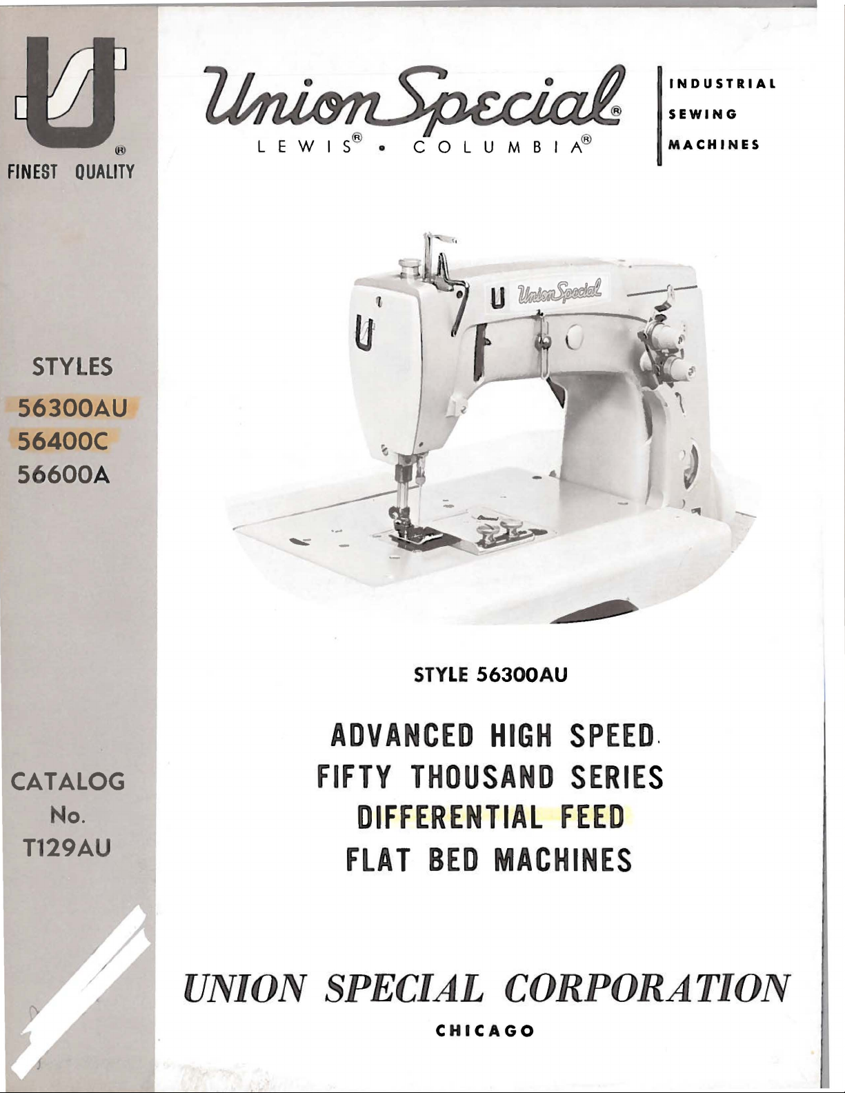
STYLES
56300AU
56400C
56600A
C 0 L U M B I A®
MACHINES
...
CATALOG
No.
T129AU
/
/
STYLE 56300AU
ADVANCED
FIFTY
THOUSAND SERIE
DIFFERENTIAL
FLAT
BED
UNION SPECIAL
C H
ICAGO
HIGH SPEED
.
S
FEED
MACHINE
S
CORPORATION
Page 2
C a t a 1 o g N
o.
T 1 2 9 A U
(S U P P
L E M E N T T 0 C A T A L 0 G N
0.
1 2 9
I N S T R U C T I 0 N S
F 0 R
A D J U S T I N G A N D 0 P E R A T I N G
L I S T 0 F P A R T S
F 0 R
Style
56300
AU
56400 c 56600 A
M)
F i r s t E d i t i o n
@ 1 9 7 6
By
U n i o n S p e c i a 1 C o r p o r a t i o n
R i g h t s R e s e r v e d i n A 1 1 C o u n t r i e s
UNION SPECIAL CORPORATION
INDUSTRIAL
P r i n t e d i n
SEWING
CHICAGO
MACHINES
U.
S.
A.
2
April.1978
Page 3
Each
the
machine.
numbers
Example:
minor
Style
changes
number. Example:
UNION
have
"Style
SPECIAL
Style
one
56300
are
numbers
or
more
made
IDENTIFICATION
machine
letters
AU".
in a standard
"Style
is
are
classified
Special
56300
identified
suffixed,
Style
machine,
AUZ".
OF
MACHINES
by a
as
standard
but
numbers
a "Z"
never
contain
Style
contain
is
number on a name
and
special.
the
letter
the
letter
suffixed
to
the
plate
Standard
"Z".
"Z".
When
standard
Styl
only
on
e
Styles
which
"Class
be
56300
trated
56400 W
56600 A
number,
of
the
use
herein.
in
are
direction
differs
This
used
AU,
another
assembly
the
This
these
given
of
machines
from
56300".
catalog
in
conjunction
56400 C and 56600 A,
and
listed
parts
parts.
part
reference
are
number,
part
or
catalog
It
can
classes.
from
of
handwheel
the
is a supplement
at
the
shown
Opposite
description
is
indicated
base
also
the
part.
number
applies
be
References
operator's
similar
style
therewith.
applied
is
STYLES
number,
APPLICATION
back
of
in
phantom
the
illustration
by
Always
in
the
specifically
to
position
toward
OF
in
construction
in
to
Catalog
Only
but
not
this
book.
to
assist
and amount
indenting
use
first
with
MACHINES
column when
discretion
direction,
the
operator.
that
OF
those
used
the
to
while
are
it
contains
CATALOG
No.
parts
on
Styles
For
in
locating
pages,
required.
its
description
part
number
the
Standard
to
such
seated
IN
CLASS
grouped
129
M,
which
56300 W
clarity,
parts
Any
in
ordering
some
as
right,
at
56300
under a class
no
letters.
Fourth
are
certain
the
56300
are
identified
part
under
the
second
repair
Styles
Special
left,
the
machine.
Edition,
used
or
of
on
56400 W
56300 W and
AU,
that
is
the
description
column,
parts.
machines
Styles
front,
number
Example:
and
should
Styles
are
illus-
56400 C and
by a reference
a component
of
never
as
listed
of
machines
back,
Operating
etc.,
Advanced High Speed
Controlled
Weight
Positive
Wakefield
and Improved
Equipped
1/4
8
56300
and
similar
401-SSa-1.
Advanced High Speed
pendent
Bearing
Single
Pumps
Travel,
for
Needle
for
Foot
Intermittent
Presser
Automatic
Bearings
with
Inches
AU
operations
Type 128
Row,
Low
Needle
Reservoir
Head and
Large
Lifter,
Bar 8
1/4
Belt
Single
Differential
Bar
and
Needle
Lubricating
for
Feed Rocker
Guard,
Disc
(209.6
Handwheel and Improved
Type
Medium
Throw,
Bar
Drive,
Enclosed
Base,
Equipped
Inches
Prepared
Thread
mm).
throw
on medium
GBS
needle.
STYLES
Two
Treadle
Wakefield
(209.6
Light
Positive
with
Needle
Bar
System,
Tensions,
machine,
to
Maximum
OF
MACHINES
Needle
Controlled
Weight
Disc
mm).
Flat
Feed,
Driving
Filtered
Shaft,
for
Use
Maximum
for
seaming
heavy
recommended
Flat
Automatic
Bearings
Type
Bed
Presser
Belt
Thread
Bed
Machines,
Needle
Mechanism,
Lateral
with
weight
IN
CLASS
Machines,
Intermittent
Lubricating
for
Guard,
Bearing
Oil
Looper
Knee
Work
side
materials.
Bar and
Feed Rocker
Prepared
Tensions,
Single
Return
Press
Space
and
speed
56400
Left
Needle
Medium
Needle
Pumps
Travel,
for
inseams
6000 R.P.M.
Needle
Differential
System,
Shaft,
for
Work
Throw,
Bar
Reservoir
for
Large
Presser
to
Right
Seam
Bar
Filtered
use
Space
Treadle
Drive,
Enclosed
Head and
Handwheel
Foot
Lifter,
of
Needle
on
knit
Specification
in
Feed,
Driving
Lateral
with
to
trousers
Front,
Needle
Mechanism,
Oil
Looper
Knee
Right
Press
Light
Base,
Bar
Inde-
Return
of
3
Page 4
STYLES
OF
MACHINES
IN
CLASS
56400
(Continued)
5640 0 C
pajamas,
modified.
speed
6000 R.P.M.
Low
etc.,
made from
Type 108
Advanced Hi gh Speed
p ·
ndent
Row,
Low
Throw,
Bearing Needle Bar
Singl
Pumps
Travel,
Needle
garments
ification
Maximum
number
The
measured
ively,
given
for
Foot Lif t e
size
e Rese
56600 A
rvoir
for Head
Larg
e Handwheel and Improved
Bar 8
1/4
Enclosed
and
r,
Equipped
Low
made from light wei
401-LSc-2
recommended
Each
UNION
denotes
number,
in
the
on
the
SPECIAL
the
stamped
thousandths
type
number and
label
throw
machine,
light
GS
needle.
STYLES
Two
Treadle
Drive,
Base,
Inch
throw
Wakefield
es (209.6mm).
machine,
modified.
speed
needle
kind
of
on
of
of
all
for
weight
Standard
OF
MACHINES
Needle
Controlled
Light
Positive
Weight
Automatic
Bearings
with
Disc
for gathering
ght
wov
en fabri
Type 108
6000 R.P.M.
has
both a type
shank,
the
an
the
needles
point,
needle
inch,
size
packaged
setting
woven
gauges
IN
Flat
Bed
Presser
Belt
Type
Thread
GS
NEEDLES
length,
shank,
midway
number
puff
sleeves
fabrics.
nos.
CLASS
56600
Machines,
Intermittent
Bar
Lubricating
for
Feed Rocker
Guard,
Prepared
Tensions,
and
cs and
needle.
similar
Standard
number and a
groove,
denotes
between
represent
and
sold
Seam
12,
16.
Right
Differential
and
Needle
System,
attaching
finish
the
the
shank
the
complete
by
Union
in
house
dresses,
Specification
Maximum
Needle
Bar
Driving
Filtered
Shaft,
for
Work
use
Space
Lateral
with
ruffles
operations.
gauges
size
nos.
number. The
and
largest
and
diameter
the
symbol,
Special.
waists,
401-LSc-2
recommended
in
Front,
Feed,
Ind
Needle
Mechanism,
Oil
Return
Looper
Knee
Press
to
to
Right
body
Seam
8,
12,
of
of
Spec-
16.
type
other
eye.
details.
of
blade,
Collect-
which
e-
is
Standard
shank,
point,
125/049,
round
chromium
140/054,
Standard
has a round
spotted,
needle,
complete
To
have
or
chromium
order
Selection
Thread
should
mation.
Success
UNION
its
approved
and
SPECIAL
subsidiaries
scientific
durability
Genuine
parts
your
are
guarantee
recommended
point,
recommended
shank,
needle
the
type
would
of
pass
in
Needles
are
needles
stamped
of
short,
plated
and
060.
round
plated
orders
and
read:
the
proper
freely
USE
the
operation
and
and
~uthorized
principles,
assured.
are
with
the
the
highest
needle
~ouble
is
available
needle
point,
and
is
promptly
size
number
"1000
needle
through
GENUINE
of
Repair
packaged
Union
quality
for
Style
groove,
for
Styles
extra
short,
available
and
should
Needles,
size
needle
NEEDLES
these
Parts
machines
as
distributors.
. and
are
with
Special
in
56300
struck
in
sizes
56400 C and 56600 A
double
in
sizes
accurately
be
Type 128
should
eye
in
AND
REPAIR
furnished
made
with
labels
trademark,
materials
AU
is
groove,
032,
groove,
036,
filled,
forwarded.
GBS,
be
determined
order
PARTS
can
be
by
They
are
utmost
marked
~
U S Emblem. Each
and
Type 128
ball
90/036,
GBS.
eye,
100/040,
is
struck
040.
an
empty
Use
description
Size
032".
by
to
produce
secured
the
designed
only
Union
according
precision.
workmanship.
It
has a round
spotted,
ball
110/044,
Type 108
groove,
GS.
ball
package, a sample
on
label.
size
of
thread
a good
Special
• Genuine
stitch
with
genuine
Corporation,
to
Maximum
the
efficiency
repair
trademark
It
eye,
A
used.
for-
most
is
. 4
Page 5
IDENTIFYING
PARTS
Where
of
the
smaller
cation
appear.
letter
Part
IMPORTANT!
WHICH
shipments
unless
PART
Prices
otherwise
construction
parts
is
stamped
numbers
represent
ON
IS
ORDERED.
are
strictly
are
forwarded
directed.
and
ALL
permits,
on
those
in
to
the
ORDERS,
net
cash
f.o.b.
A
each
where
distinguish
same
part,
PLEASE
TERMS
and
shipping
charge
is
part
is
construction
the
regardless
INCLUDE
are
subject
point.
made
to
stamped
part
PART
NAME
to
Parcel
cover
with
does
from
of
change
Post
the
its
not
similar
catalog
AND
STYLE
without
shipments
postage
part
permit,
ones.
in
OF
and
number.
an
identifi-
which
they
MACHINE
notice.
are
insured
insurance.
On
FOR
All
some
5
Page 6
-
FILL
MAIN
RESERVOIR
HERE
FOR
CORRECT
OIL
LEVEL
NEEDLE
SHOULD
OPERATE
OF
GAUGE
BE
IN
POSITION
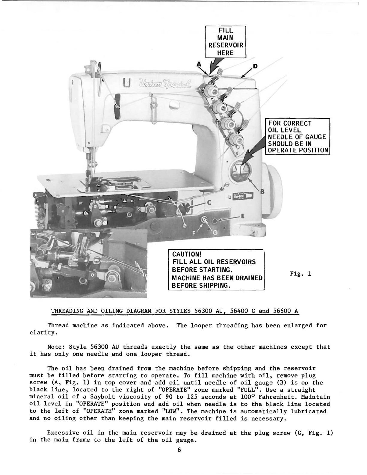
Thread
clarity.
Note:
it
has
The
must
be
screw
black
mineral
oil
level
to
the
and no
THREADING
machine
Style
only
one
oil
has
filled
(A,
line,
oil
left
oiling
before
Fig.
1)
located
of a Saybolt
in
"OPERATE"
of
"OPERATE"
other
AND
OILING
as
56300
needle
been
in
to
than
DIAGRAM
indicated
AU
threads
and
one
drained
starting
top
cover
the
right
viscosity
position
zone marked
keeping
above.
looper
from
to
and
of
and
the
CAUTION!
FILL ALL
BEFORE
MACHINE
BEFORE
FOR
STYLES
exactly
thread.
the
machine
operate.
add
oil
"OPERATE"
of
90
add
oil
"LOW".
main
OIL
RESERVOIRS
STARTING.
HAS
BEEN
SHIPPING.
56300
The
looper
the
same
To
fill
until
zone marked "FULL". Use a
to
125
when
The
reservoir
AU,
threading
as
before
machine
needle
seconds
needle
machine
filled
DRAINED
56400 C and 56600 A
the
other
shipping
with
of
oil
at
100°
is
to
is
automatically
is
has
been
machines
and
the
oil,
gauge
Fahrenheit.
the
necessary.
remove
(B)
black
Fig.
enlarged
except
reservoir
plug
is
on
straight
Maintain
line
located
lubricated
1
for
that
the
in
Excessive
the
main
oil
frame
to
in
the
the
main
left
reservoir
of
the
oil
may
be
gauge.
6
drained
at
the
plug
screw
(C,
Fig.
1)
Page 7
INSTRUCTIONS
LUBRICATION
FOR
MECHANICS
CAUTION!
reservoir
before
the
damage.
Fahrenheit
No.
(D)
needle
Oil
"OPERATE"
cans
CAUTION!
an
and
further
distribute
beginning
oil
to
Use a
175.
and
check
is
should
No. 28604 R.
It
is
extended
directly
hand
Oil
has
must
Fill
be
to
the
various
straight
in
the
main
oil
to
the
black
be
added
zone,
It
marked
is
important
recommended
period
oil
the
oiling
oil
to
been
drained
filled
operate.
parts.
mineral
main
reservoir.
reservoir
level
line,
when
"LOW".
that
be
lubricated
needle
will
the
various
to
at
gauge
needle
that
be
from
the
Run
Full
oil
at
located
The recommended
a new
bar
required.
parts.
the
main
proper
machine
RECOMMENDED
of a Saybolt
plug
(B).
is
these
as
link
level
speed
This
is
screw
Oil
to
the
to
the
machines
machine,
follows:
and
Run
reservoir
as
slowly
operation
equivalent
is
black
the
machine
OIL
viscosity
(A,
Fig.
at
right
oil
not
or
one
Remove
needle
for
maximum
before
indicated
several
can
of
to
1)
of
"OPERATE"
line,
located
is
available
be
over
that
the
bar.
slowly
has
on
then
90
Union
in
upper
safe
filled.
been
head
Replace
for
shipment,
oil
gauge
minutes
be
expected
to
125
Special
crank
operating
zone,
to
the
in
out
cover,
head
several
so
the
(B,
Fig.
to
distribute
without
seconds
specification
chamber
marked "FULL".
left
16
fluid
of
clean
cover
minutes
at
level
of
ounce
service
out
as
1)
100°
cover
when
for
lint
no
to
For
able
operating
NOTE:
assembling
when
be
intervals.
(C,
Fig.
the
lower
Looper
spot
The
reservoir.
followed:
1.
2.
3.
4.
machines
hours.
1)
located
crank
avoid
be
sure
screw
oil
gauge
Should
Place
Remove
to
Make
Remove
the
drain
sure
in
operation
If
dirty,
Oil
may
below
chamber
and
oil
is
in
is
an
adjustment
machine
the
oil
oil
all
lower
change
be
the
cover,
feed
holes
time
set
at
reservoir
from
oil
crank
check
drained
cloth
located
lift
in
the
spot.
the
become
upright
the
reservoir.
is
drained
chamber
the
the
oil.
from main
plate
at
eccentrics
eccentric
OIL
GAUGE
factory
necessary,
on a
plug
screw
from main
cover,
oil
An
at
the
to
level
located
for
oil
reservoir
front
back
receive
line
show
table
(C,
reservoir.
dirt
and
change
of
the
of
machine.
oil
up
with
the
proper
however,
or
Fig.
at
1)
the
lint
is
recommended
by
removing
machine,
thru
oil
oil
the
bench.
and
back
deposits
the
mainshaft,
holes
level
following
tip
machine
of
the
every
plug
or
by
in
in
machine.
at
reason-
2000
screw
removing
so
mainshaft
the
steps
forward
should
when
5.
Fill
6.
main
knee
press
Loosen
the
left
reservoir
lock
or
shaft
nut
right
to a level
bushing
(F) on
until
even
(E,
Fig.
calibrating
the
gauge
1).
needle
7
with
screw
the
(G),
rests
bottom
and
on
contour
turn
the
the
black
of
screw
line,
the
to
Page 8
OIL
GAUGE
(Continued)
7.
8.
Remove
chamber
needle
inside
chamber
lever
stud
wardly
the
inside
just
above
stop
collar.
on
the
clearance
located
Tighten
cover.
Add
right
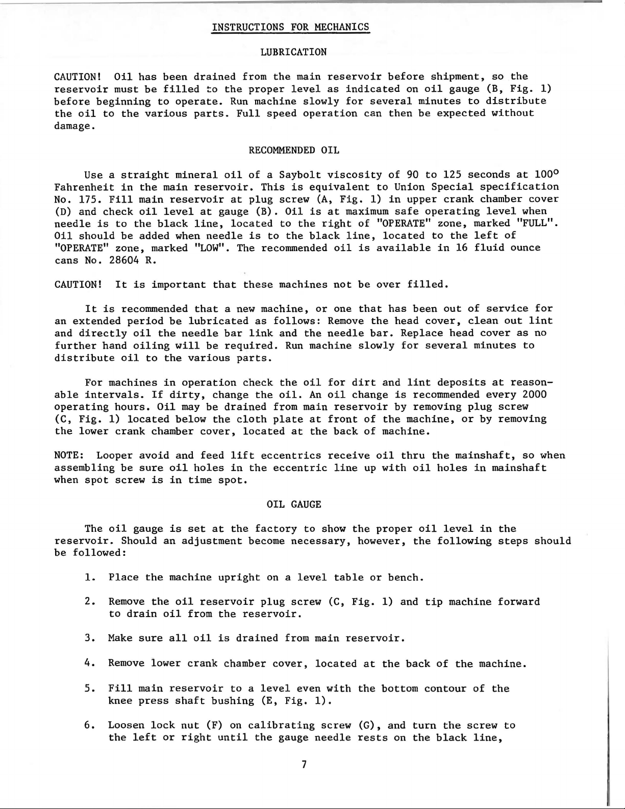
NEEDLE
cover
lever
the
arm
cover,
(B).
and
that
wall
the
needle
as
to
lock
oil
so
of
"OPERATE"
LEVER
the
head
(D,
Fig.
bearing
casting,
which
Make
its
of
notch
(Do
not
lever).
in
Figure
the
left
nut
that
BEARING
cover
1).
oiler
below
lubricates
sure
delivery
the
bed
of
the
allow
Allow
2.
of
(F) and
gauge
zone,
Check
(A,
it
end (C)
casting
needle
the
1/64
ALIGNING
"OPERATE"
replace
needle
rests
marked "FULL".
OILER
and
upper
position
Fig.
2)
the
upper
the
needle
is
tilted
contacts
at
the
lever
oiler
to
inch
THE
(TWO
NEEDLE
zone,
plug
on
crank
of
located
crank
down-
back,
shaft
rest
(.40mm)
NEEDLE
MACHINES)
marked
screw
the
black
BAR
"LOW".
(C) and
line,
lower
located
Fig.
crank
2
chamber
to
the
Align
PI40
A.
See
set
of
needles
correspond
needle
bar
Fig.
the
chart
with
clamp
3
needle
bar
below.
(Type and
the
vertical
screw
(A,
Fig.
3)
with
the
proper
If
test
Size
faces
(B,
Fig.
Machine
56400 C-12
plate
as
required)
3)
of
the
and
Styles
and
turn
test
and
needle
bar
Test
pins
align
guard.
as
698 AP-12
56400 C-16 698 AP-16
56600 A-8 698 H-2
56600 A-12 698
56600 A-16
698
SYNCHRONIZING
Insert
wheel
(A,
Fig.
of
the
with
respect
the
reverse
the
left,
the
motions
with
tion
from
respect
of
the
greatest
tion
move
the
rear.
in
needle
the
operating
4),
moving
(B).
to
direction
and
is
synchronize,
to
.005
inch
eye
of
when
the
the
looper
Moving
looper
direction
to
Note
the
looper
even
the
looper
(.127mm)
the
needle
pulley
it
in
the
until
with
drive
in
reverse.
test
are
the
required.
Plate
H-4
H-4~
LOOPER
the
until
left
the
height
point,
the
the
the
height
point
is
allowable.
to
is
turned
shaft
the
opposite
plate,
not
available,
needle
To
bar
align
Tighten
No.
AND
NEEDLE
looper
rocker
the
is
even
of
the
then
looper
left
side
of
will
be
the
point
in
the
synchronizing
direction
using
so
needle
Test
PI40
PI40
PI40
PI40
PI40
MOTIONS
point
with
eye
turn
point
of
the
eye
the
If
of
the
operating
test
insert
that
needles
bar,
clamp
Pin
screw.
No.
A
A
A
A
A
and
turn
of
the
the
left
of
the
handwheel
again
the
needle.
of
the
same. A
the
distance
looper
stud
acts
pins
a
loosen
hand-
looper
side
needle
in
moves
needle
varia-
is
direct-
(C)
the
No.
new
to
If
to
8
Page 9

SYNCHRONIZING
LOOPER
AND
NEEDLE
MOTIONS
(Continued)
Moving
follows:
(away from
that
is
required.
throat
light
is
screw
If
the
stud
plate
tap
required.
(D)
gauge
is
center
should
of
the
Loosen
operator),
support,
on
the
Note
Fig.
and
reposition
not
available
line
of
be 4 1/16
looper
the
clamp
To
move
looper
Looper
4
the
a
light
oil
drive
drive
the
looper
inch
drive
stud
reservoir
setting
lever
screw
tap
forward
lever
lever
looper
rocker
(103.19mm)
shaft
(D)
of
the
with a small
(toward
top
cover
rocker
drive
can
(G,
be
cone
shaft,
Fig.
ring
end
drive
"O"
seal
the
end
the
ing
Remove
gauge
the
side
adjustment
lever
checked
and
(Fig.
synchronizing
looper
play
ring
bed
of
center
rod
gauge
4).
drive
hammer,
operator),
and
oil
reservoir
toward
4)
has
and
between
must
lever
collar
With
over
of
the
rocker
until
make
casting.
the
its
travel,
line
bearing,
nut
(E,
threaded
should
the
looper
is
(G)
as
with a scale.
center
directly
it
be
looper
necessary,
stud
lever.
the
oil
and
drive
metal
of
Fig.
required.
line
is
remove
operator,
seal
the
removed from
shaft
lever
Tighten
at
check
the
using
4)
stud.
locate
rocker
The
of
accomplished
To
move
on
the
the
back
collar
bed
by
to
metal
screw
the
the
right
gauge
and
The
against
cone
loosen
Tighten
distance
the
stud
stud
cloth
cover,
is
casting.
the
compressing
(G)
and
extreme
location
looper
No. 21227
place
left
(F).
looper
to
is
plate,
then,
all
that
and
an
All
looper
the
contact
(D).
right
connect-
hole
end
the
right
If
the
clamp
clamp
between
lever
as
rear
all
a
"O"
the
oil
with
of
ex.
in
of
screw.
Machine
Style
Fig.
5
Needle
cified.
for
distance
point
the
right.
vantageously
needle
needle
chart
looper
loosen
thread
the
the
nuts,
left
not
Type
SETTING
Insert
example,
of
looper
when
for
connecting
1/8
first
ball
bind
Looper
a
If
the
from
the
is
Looper
machines
setting
needle
gauge
nut
(C,
and
nut
inch
nut
joint
after
Setting
THE
new
needle,
looper
set
the
the
center
looper
at
its
gauge
in
making
set
Type,
number.
Fig.
(D)
on
rod
forward
(3.17mm)
(D),
is
in
adjustment.
Gauge
LOOPER
type
gauge
looper
of
is
1/8
farthest
No.
21225-1/8
this
the
back
the
looper
looper
If
adjustment
5)
(it
connecting
dimension.
then
nut
vertical
and
size
is
1/8
inch
(A,
Fig.
the
needle
inch
has a left
or
(3.17mm), when
position
can
adjustment.
looper
gauge.
gauge
is
rod
backward
Retighten
(C).
Make
position
Looper
as
(3.17mm),
5)
so
(B)
to
be
On
to
the
Refer
setting
required,
hand
(E),
to
sure
and
Gauge
Number
spe-
the
to
the
used
two
right
to
and
turn
obtain
both
does
the
ad-
the
56300
56400 c
56600 A
AU
128
108
108
GBS
GS
GS
9
5/32
1/8
1/8
Inch
Inch
Inch
(3.97mm)
(3.17mm)
(3.17mm)
21225-5/32
21225-1/8
21225-1/8
Page 10

The
behine
the
needle
Fig.
loopers.
other
looper
looper
the
than
in
is
needle,
(B).
6
The same
applying
looper
rocker,
SETTING
set
correctly
its
point
If
turn
stop
the
looper
reverse.
may
prove
recheck
On
(A,
adjustment
screw
to
Holding
helpful.
the
adjustment.
the
two
looper -needle
pressure
so
on
as
in
line-of-feed,
Fig.
(G)
the
rear
looper
needle
relation
the
to
get
THE
6)
brushes,
is
necessary,
as
required.
and
Tighten
machines,
looper
the
LOOPER
turning
to
the
lock
should
at
front
proper
(Continued)
if,
as
it
moves
but
does
not
loosen
Turning
front
screw
now
exist
or
lock
stop
it
counterclockwise
while
when
insert
without
back
of
in-line-of-feed
to
pick
screw
screw
making
setting
the
other
any
blade,
setting.
the
left,
at
the
rear
(F,
Fig.
clockwise
acts
this
adjustment
is
obtained
needles
adjustment,
while
of
5)
and
sets
the
and
and
clamping
The
3/64
with
move
not
or
inch
the
needle
to
down.
The
slots
The main
imately
The
feed
travel.
height
left
disturb
needles
in
throat
3/64
dog
of
(1.19mm)
side
bar
(A)
the
plate.
feed
inch
should
SETTING
the
needles
below
of
up
the
or
the
needle.
down
alignment
are
to
have
SETTING
dog
should
(1.19mm) above
be
centered
HEIGHT
(C,
Fig.
underside
If
as
required
of
the
needle
equal
clearance
THE
be
set
the
in
the
OF
NEEDLE
3)
are
of
the
adjustment
and
bar
on
MAIN
to
throat
slots
rise
FEED
the
plate,
of
BAR
correct
looper,
is
when
with
necessary
retighten
when moving
the
right
DOG
depth
the
at
throat
the
of a full
the
the
,
screw.
the
and
highest
plate
top
looper
loosen
Care
needle
left
tooth,
at
of
point
screw
should
bar
sides
point
maximum
its
or
of
eye
flush
(B)
be
either
of
needle
approxtravel.
feed
is
and
taken
up
Fig.
7
To
screw
dog
at
NOTE:
raise
(A,
specified
A
or
Fig.
change
lower
8) up
height.
of
or
feed
the
main
down
Retighten
dog
height
feed
under
dog,
the
screw
will
loosen
feed
dog
(A).
necessitate
allen
holder
a
setting.
10
Fig.
screw
(B,
check
(A,
Fig.
of
8
7)
the
Fig.
to
rear
7) and
set
the
needle
adjust
feed
guard
Page 11

SETTING
THE
MAIN
FEED
DOG
(Continued)
The main
throat
feed,
(C).
bar
To
as
The
above
of
the
feed
dog
of-feed.
plate
loosen
adjust
required.
differential
the
throat
throat
should
feed
at
maximum
screws
main
plate,
plate
be
dog
should
feed
(C,
Fig.
feed
dog
Retighten
SETTING
feed
at
at
maximum
parallel
have
travel.
7) and
equal
To
position
in-line-of-feed,
nut.
Fig.
THE
DIFFERENTIAL
dog
should
the
highest
feed
to
the
travel.
top
clearance
adjust
9
also
point
surface
be
In
the
feed
loosen
FEED
set
of
travel
addition
of
on
main
dog
to
the
all
as
nut
DOG
rise
and
throat
sides
feed
dog
required.
(A,
Fig.
the
center
to
this
plate
of
feed
slots
across-the-line-of-
Retighten
9) and move
depth
in
the
of a full
the
feed
teeth
across-the-line-
of
in
the
screws
feed
tooth
slots
the
To
raise
the
feed
dog
Loosen
or
backward
ential
alled
screws
NOTE:
through
or
the
feed
with
securely.
Turn
its
throat
These
when
(E,
and
the
Fig.
9).
turning
treadle
These
2~
to 1 depending
hand
its
making
travel
or
lower
at
the
set
screws
as
required.
bar
(D)
the
top
machine
cycle
plate
machines
is
Turning
it
clockwise
machines
on
sure
or
the
the
the
differential
required
to
surface
by
hand
and
does
at
SETTING
have
used.
it
(C,
be
the
counterclockwise
height.
Fig.
The
loosening
rotated,
of
the
to
make
not
forward
THE
an
intermittent
The
differential
decreases
have a stretching
the
length
differential
throat
plate
feed
Retighten
9) and
move
of
so
the
throat
sure
the
contact
end
the
of
DIFFERENTIAL
the
amount
ratio
of
stitch
feed
dog
at
the
forward
dog,
screw.
the
differential
set
screws
differential
plate,
across-the-line-of-feed.
differential
main
its
feed
travel.
FEED
differential
feed
ratio
increases
of
differential
of
3/4
set
at
the
clears
end
loosen
(C)
dog
TRAVEL
feed
is
the
amount
to 1 up
main
the
main
of
its
screw
(B,
feed
will
feed
at
feed
also
dog
dog
back
which
set
by
of
feed.
to a gathering
feed
dog.
feed
travel.
Fig.
bar
(D)
allow
can
be
aligned
has
clearance
end
of
is
activated
turning
differential
Turn
at
the
back
9) and
set
forward
the
differ-
par-
Tighten
its
travel
only
thumbscrew
feed
ratio
machine
end
of
by
of
11
Page 12

ing
stud
damage
slot
in
toward
to
the
the
Fig.
feed
ferrule
10
the"L").
drive
(E).
accomplished
turn
stitch
ing
plate,
marked
shortens
toward
direction
Retighten
bearing,
Set
(it
has a left
regulating
screw
in
with
the
the
locknut
the
Key
CHANGING
the
stitch
by
(B)
located
the
head
"L" and
the
stitch
"S")
lengthens
screw
STITCH
to
required
loosening
hand
stud
and
under
of
the
"S".
(moves
and
turning
the
securely.
{D)
must
LENGTH
the
thread)
turning
the
main
Turning
stitch
it
stitch
To
engage
length.
locknut
on
left
shaft
the
regulating
the
the
end
(C),
screw
This
(A,
end
stitch
of
is
Fig.
10)
of
the
adjust-
the
which
clockwise
stud
in a counterclockwise
(moves
prevent
stitch
destructive
the
"U"
regulat-
shaped
~
cloth
is
key
NOTE:
rear
Any
needle
Set
contact
A
clearance
sible,
yet
needle,
To
move
retighten
NOTE:
Any
Draw
of
fabric.
The
controls
It
should
(C)
and
almost
up.
the
The
affects
to
the
left.
horizontal
stitch
up.
thread
when
However,
triangle
causing
checked
looper
moves
change
guard
the
rear
the
rear
of
have
until
needle
screw.
change
looper
Refer
looper
the
amount
be
set
the
tip
limit
height
the
control
Ordinarily
position.
the
if
triangle
by
observing
to
of
.005
its
the
guard
in
and
to
thread
laterally
parallel
of
and
retainer
the
may
skips
the
in
stitch
setting.
needle
the
inch
vertical
point
merely
stitch
needle
threading
SETTING
cast-off
of
slack
its
the
lateral
of
the
More
retainer
be
wiped
or
the
left.
length
SETTING
guard
right
(.127mm)
face
of
the
loosen
length
threads
THE
thread
so
with
slot
so
looper
it
will
looper
is
raised
is
under
pulled
action
will
THE
REAR
(B,
Fig.
needle
(C) when
is
permissible.
approach
looper
screw
will
THREADING
into
diagram
LOOPER
wire
(A,
in
that
it
the
discs.
that
it
adjustment
thread
be
set
thread
and
raised
the
down
of
the
THREAD
necessitate
NEEDLE
8)
horizontally
within
moving
(D),
require
the
(Fig.
1)
THREAD
Fig.
the
system
is
midway
It
is
barely
of
as
the
in
approximately
is
given
set
toward
too
high,
blade
of
stitches.
looper
TENSIONS
a
GUARD
at
its
It
about
to
the
left,
move
needle
a
change
machine
for
manner
CAST-OFF
11)
located
and
between
usually
clears
the
retainer
looper
to
the
the
the
the
looper,
This
thread
corresponding
so
that
most
should
3/64
forward
be
inch
is
even
guard
in
rear
and
start
of
threading
WIRE
on
the
can
be
moved
the
two
set
toward
the
highest
moves
a
take-
looper
can
be
as
the
change
it
does
point
set
as
(1.19mm)
with
as
required,
needle
operating
cast-off
to
any
discs
of
the
point
in
not
of
travel.
low
as
of
the
needle.
guard
on a
this
support
position.
the
take-up
of
the
Fig.
11
the
quite
pos-
the
and
setting.
piece
mach~ne.
(B)
take-up
to
take-
The
stitches
just
sufficient
tension
on
the
on
the
under
to
steady
needle
surface
the
thread
of
the
thread.
should
fabric.
be
only
Tension
sufficient
on
12
the
to
looper
produce
thread
uniform
should
be
Page 13

The
presser
entirely
If
located
tighten
thread
foot
released
adjustment
at
screw.
the
is
back
After
tension
raised
to
when
the
is
needed,
of
the
adjustment
THREAD
release
within
presser
machine
is
1/8
loosen
there
TENSION
set
correctly
inch
foot
has
tension
and
move
should
RELEASE
(3.17mm)
reached
release
tension
be
no
when
of
its
disc
binding
it
the
highest
lever
begins
end
of
screw
separator
at
any
to
function
its
travel
position.
(A,
Fig.
as
required.
point.
as
and
12),
the
is
Re-
The
remove
Also
between
(E,
when
resting
throat
ion
(F,
plate
screw
en
is
mentioned
only
tension
the
pressure,
the
there
Fig.
the
plate.
If
until
Fig.
surface,
driver
screw.
in
its
Regulate
enough
needle
height
lower
3)
foot
on
adjustment
the
3).
Check
high
in
is
placed
bar
counterclockwise
of
presser
should
surface
and
the
lifter
the
throat
needle
Then,
pry
to
obtain
setting
position
previous
the
pressure
in
the
foot
be
is
while
up
presser
on
the
SETTING
presser
when
approximately
of
bottom
lever
plate,
needed,
bar
presser
the
by
and
paragraph.
on
the
the
head
the
the
presser
surface
is
released
with
turn
is
in
holding
bar
1/16
turning
see
PRESSER
spring
presser
fabric.
of
the
acts
HEIGHT
bar
(D,
foot
1/16
of
the
handwheel
the
low
presser
connection
inch
handwheel
if
presser
regulating
foot
This
machine.
the
reverse.
OF
PRESSER
Fig.
lifter
inch
bar
connection
head
opening
and
the
feed
dog
position.
foot
(1.59mm)
foot
FOOT
is
PRESSURE
to
the
3)
is
lever
(1.59mm)
presser
down
in
operating
Loosen
down
and
guide
setting
so
that
can
screw
feed
the
knurled
Turning
BAR
set
(B,
and
in
below
on
needle
be
(A,
work
screw,
it
correctly
Fig.
12)
clearance
guide
the
bed
foot
the
direct-
screw
the
throat
with
a
and
tight-
bar
removed
Fig.
13)
uniformly
located
clockwise
if
it
is
fully
as
so
that
increases
is
possible
depressed.
Fig.
it
when a
directly
to
12
exerts
slight
behind
the
(B,
Fig.
bar
thread
surface
the
needle
bar
has
this
setting
loop,
the
needle
the
eyelet
the
attaching
Set
the
13),
is
completed
and
raise
SETTING
needle
located
eyelet
even
with
bar
thread
for a smaller
it
thread
hole
is
screw.
NEEDLE
thread
adjacent
(C),
so
that
the
top
eyelet
its
downward
needle
for a larger
frame
3/4
eyelet
inch
THREAD
take-up
to
its
of
the
when
stroke.
loop.
(D)
(19.05mm)
TAKE-UP
wire
the
needle
upper
holes
the
needle
thread
so
that
above
in
Lower
Set
13
WIRE
AND
FRAME
EYELET
~
/
~
~9.05
D
Fig.
13
Page 14

30
33
ft
~
14
Page 15

The
parts
the pnrtll
illustrated
that
nr c u!lcd on
on pa
ges
14,
Style!!
16,
18, 20 and 22, and
56300
AU,
56400 C and 56600
described
A,
but
on
not
this
use
page,
on
page
Styles
17,
19,
56300 W
21
or
and 23
56400
represent
W.
Unless othcrwidc spec
ca
talog.
and 56600
Usc
ports
Reference
they
He
f.
No.
1
2
3
4
5
6
7
8
9
10
11
12
13
14
15
16
17
18
19
20
21
22
23
24
25
26
27
28
29
30
31
Catalog
not
are
component
29476
55235 E
6042 A
55235 D
22768 B
56336 B
56336
51054
22801
57822 A
56322 B
22891 B
57847
56323 A
22580 D
29476
22894
29476
22894
57836 E
22768 B
22894
57846 B
52889 A
51256
53688
51617 B
The
parts shown
A.
No.
129 M
illustrated
numbers
Part
No
.
ND
c
666-149
95
NM-062
77
AA
NM-072
77
AA
AA
c
-8
that
parts
51617 B-12
51617 B-16
C-12
51417
32
33
34
35
36
37
38
51417 C-
51418-16
21210
51609
51608 A-8
50
89
98
16
J-16
A
51608 A-12
51608 A-16
39
40
41
42
43
44
45
46
47
48
49
50
51
51204 A
51204 c
77
51204 B
J87 J
22798 A
22569 D
21657 E
51204
56357 B
57841
c
22729
57744
51270 B
51292 F
-2
ifi
ed
in
the
in
phantom
Fourth Edition
or
described
arc
inside a bracket
of a complete
LOOPERS,
Fe
ed Rocker
Nut
Washer
Locking
Screw,
Feed Crank
Feed Crank
Screw,
Main
for
Shaft
GasketOil
Thrust
Collar
Screw - - -
Take-up
Set
Looper Avoid
Screw - - - - - Screw - - - - - - - - - - - - - - - - -
F
eed Lift
Screw - - - - - - - - - - - - - - - - - - Screw - - - - - - - - - - - - - - - - - -
Di
fferential
Screw Screw - - - - - - - - - -
Looper Rocker Cone
Presser
Presser
Presser
Needle
Needle
Needle
Needle
Needle
Spring
Spring
Bar - - - - Bar,
Bar,
Bar,
Bar,
Bar,
Stop
Stop
Screw - - - - - - - - - - - - - - - - - - -
Set
Screw,
Needle
Looper
Looper,
Looper,
Looper,
Looper,
Looper
Holder,
Collar,
back,
front,
front,
front,
Thread
Cast-off
Screw
Cast-off
Screw
Screw
Screw
Washer
Looper
Cast-o
Looper
Thread
f f
Connecting Rod Ball
Screw - - - - - - - - - - - - - Loop r Rocker
Needle
Looper
Thread
Thread
description,
views
and
Style
this
56300 W
catalog.
in
or
part
or
FEED
CRANK,
FEED
Arm
and Feed Crank
- Stud
for
link
Link
Feed Crank
Link
Oil
Wick
take-up
- - - - -
- - - -
Flow Reg
ulating
Screw -
Eccentric
Eccentric
Feed
Connecting
Stud
Regulator
- - - - - - -
marked "DH-8",
marked "DH-12",
marked "DH-16",
marked "CV-12",
marked "CV-16",
Pin-
for
needle
marked
for
Style
for
all
for
No.
for
No.
for
No.
Retaining
and
Retaining
Retainin
Plate
Support
Shaft-
Take-up Wire
Tension
the
parts arc
bearing
for
box on
the
no
reference
56300
picture
used
AU,
on
numbers
and
pla
assembly.
MAIN
LIFT
BARS
SHAFT,
AND
AND
LOOPER
CAST-OFF
LOOPER
AVOID ECC
PLATE
ROCKER
Description
Link
Sub-Assembly
pin
Assembly
Link
Pin
Ferrule-
-
-
Screw -
.062
inch
Assembly,
Assembly,
.072
Rod,
inch
.080
(1.58
(1.83
inch (2.03
Nut-
-
for
No. 8 gauge,
for
No.
12
for
for
for
No.
No.
No.
16
12
16
gauge,
gauge,
gauge,
gauge,
- - - - - - - - - - - - - - -
"D-16",
for
all
gauges,
56600 A - - - - - - -
gauges,
8 gaug
12
16
Finger
g Fing
gauge,
gaug
Finger
er
Style
e,
Style
Style
e,
Style
Holder
Support
56600 A - - - - -
56600 A
56600 A - 56600 A - -
- - - - -
Brack t-- -
- Joint, lef t
- - - - - - - - - (not
Spr
i ng ,
shown)
for
Styles
56400 C and 56600 A
15
all
the
machine
are
common
Style
56400 W for 56400 C a
te
and hove
indente
SHAFT,
ENTRICS,
mm)
Style
Style
Style
Style
Style
Styles
NEEDLE
mm)
throw
throw-
mm)
throw
56600 A
56600 A
56600 A
56400 C
56400 C
56400 C and 56600 A
styles
to
d d
(not
covered
Styles
56300
nd
escriptions,
shown)
in
this
AU,
56400 C
56600
A,
for
indicate
- - - - - - 1
- - - - - 2
all
Amt.
Req.
1
1
1
1
1
1
1
1
1
1
1
1
1
2
1
2
1
1
1
1
1
1
1
1
1
1
1
1
1
1
1
1
1
1
1
1
2
1
2
1
1
1
1
1
1
1
1
2
1
2
2
1
1
1
1
1
2
Page 16

\
\
'
'\
\
'\
'\
'
'\
'
" '
'\
.-
\
~~
3DA
3DB
~
37
36
16
Page 17

DIFFERENTIAL
FEED
MECHANISM
Ref.
No.
1
2
3
4
5
6
7
8
9
10
11
12
13
14
15
16
17
18
19
20
21
22
23
24
25
26
27
27A
28
29
30
30A
30B
31
32
33
34
35
36
37
38
39
40
41
thru
Part
No.
57835
CL-21
57836 G
56336
J
57836 A
56334 R
55235 E
6042 A
57836 D
57836
c
57836
57834 B
56335 D
98
22894 E
57834 E
22651
CB-4
57834 D
57834 G
22637
P-24
57837 D
57853
57834
c
22593
22593
52953 A
52853
22653 B-14
51235 G
51225 B
51425
AC
51625
52925 D
22635 E-24
CL-21
57834 A
CL-21
90
51236 A
57837 F
22738 B
75
Description
Main Feed Rocker
Oil
Wick- - - - - - - -
Differential
Gather
Differential
Feed
Shaft,
Drive
lower
Rocker
Feed Rocker
Shaft-
Bushing
Bushing
- - - - - - 2
Nut
Washer
Locking
Stud
Main Feed Rocker - - - - -
Bushing
Main Feed Rocker
Collar,
for
lower
Shaft,
main
upper
feed
- - - -
rocker
driving
shaft
Screw - - - - - - - - - - - - - - - - - - - -
Set
Screw,
for
No.
57837 C - - - -
Main Feed Bar - - - -
Screw - Bushing
Bushing
Feed
Differential
Dog
Feed
Oil
Wick
Screw,
Screw,
for
for
Main Feed
Dog
Feed
Feed
Dog
- - - - - - - - - - - -
-
Dog
Height
Adjusting
Feed Bar Guide
Holder
Retainer
main
Dog
Holder,
Holder,
Support
- - -
- - - - - - -
oil
wick
feed
retainer
dog-
- - - -
(See Page 23) - - - - - -
for
Style
for
Styles
Screw
Plate
56300
-
AU
56400 C and 56600 A
Screw - - - - - - - - - - - - - - - - - - - Washer - - - - - - - - - - - - - - - Rear
Needle
Rear
Needle
Rear
Needle
Needle
Guard
Guard,
for
Style
56300
Guard, marked "FT",
Guard, marked "FX",
Holder
- - - - - - - - - -
for
for
AU
- - - - - - - - - Style
Style
56400 C
56600
Screw - - - - - Oil
Wick- - - - -
Differential
Oil
Screw,
for
Differential
Link
Pin
Differential
Feed
Bar
Wick - -
differential
Feed
Dog
feed
(See
Page 23)
- - - - - - - - - - - Driving
Link
Collar-
Screw - - - - - - -
See
Following
Page
- - - - 1
A-
Amt.
Req.
1
1
1
1
1
1
1
1
2
1
3
2
1
1
1
2
2
1
1
1
1
2
2
1
1
1
1
1
1
1
1
1
1
1
1
1
1
1
1
1
1
17
Page 18

~~
3DA
308
~
37
36
18
Page 19

DIFFERENTIAL
FEED
MECHANISM
Ref.
No.
1
41
42
43
44
45
46
47
48
49
50
51
52
53
54
55
56
57
58
59
60
61
62
63
64
65
66
67
68
69
70
71
72
73
74
75
thru
Part
No.
40
57835 B
22758 E
57835 D
57835
c
57837 c
51235 p
258 A
51235 R
56335 R
9663
56335 N
59448
22548
35751 D
51216 N
93
A
69
H
51283 A
9937
20
51235 s
28
56335 M
H
69
57835
EA
12934 A
907
80265
57837
57836
F-40
57836 F-45
57836
F-50
57837 A
22868 B
61341
J
57837 E
22743
Description
See
Preceding
Intermittent
Screw,
for
Differential
Differential
Differential
Thumbscrew,
NutRatchet
- - - - - - - - - - - - - - - - - - - - - Nut-
Bracket,
Screw-
Stop
- - - - - - - - - - - - -
Block
Differential
Screw-
Screw-
-
- Washer - - - - Screw-
- - - - Washer - - - - - Differential
Nut-
- - - - - - - -
Washer - - -
Ratchet
Screw,
Spring
for
Differential
Washer - - - - - - - - - - - - Differential
NutNut-
- - - - -
- - - - - - - - -
Page
Differential
differential
Feed
Feed
Feed
for
adjusting
for
differentifal
Control
Control
Control
Feed Bar
feed
control
Lever
LeverLever
differential
feed
Link
- - - - - -
Bushing
adjusting
- - - - - - - - - - - - Feed
Feed
Stop
Return
Block
Spring
Bracket
- - - - - -
ratchet
Feed
Feed
spring-
Control
Control
Lever-
Indicator-
Driving
lever
Link-
link-
- - - - - 1
- - - - - 1
- - -
- - - - - 1
feed-
screw-
- - - - - - - - - 1
- - - - - - - - - - 1
- - - - - - - - - 1
- - - - - - - - - 2
- - - - - 1
- - - - - 1
- - - - - 1
- - - - - - 1
- - - - - 1
- - - - 1
- - - - - - - 1
- - - - 1
- - - - - - 1
- - - - 1
- - - - 1
- - - - - 1
- - - - 1
- - - - 1
- - - - 1
Washer - - - - - - - - - - - - - - - - Differential
Sliding
Sliding
Sliding
Differential
Differential
Thrust
Driving
Washer,
Link
Screw-
Feed
Block,
Block,
Block,
Feed
Feed
Link
marked "N", • 2540
marked
marked
"P",
"R",
Link
Regulating
for
feed
Guide
- - - - - - - - - -
Sleeve,
.2545
.2550
Sleeve,
bar-
left-
inch
inch
inch
right
Screw -
- - - - - -
- - - - -
(.6
.452
mm)
wide(6.464
(6.477
mm)
mm)
wide-
wide-
- - - - - -
- - - - - - - - - 1
Amt.
Req.
1
1
1
1
2
1
1
1
1
1
1
1
2
- 2
19
Page 20

6
15
7
8
t
20
Page 21

CLOTH
SUPPORT,
PLATES,
ATTACHMENTS
CLOTH
PLATE
AND
COVER,
STRIPPER
THROAT
BLADE
PLATE
Ref.
No.
1
2
3
4
5
6
7
8
9
10
11
12
13
14
15
16
17
18
19
20
21
22
Part
No.
57801
22526
22526 c
22839 E
22839
56401 A
22839
22839
57880
56480
51280
23425 v
23253 F
23253 z
39152 U-4
23233 A
22513
23233
23233 B
51444-12
51444-16
22704
23425
56381-212
56381-207
56381-219
c
c
J
25
c
158 B
A
98
c
v
25
c
Description
Cloth
Screw,
Screw,
Screw,
Screw,
Cloth
Screw,
Screw,
Throat
Throat
Screw,
Washer
Attachment,
Attachment,
Shim,
Looper
Screw,
Attachment,
Stripper
Stripper
Screw,
Washer
Screw,
Cloth
Cloth
Cloth
Plate,
for
for
for
for
Plate,
for
and 56600 A - - - - - - - - - - - - - - - - - - - - - - - - 2
for
Plate
Plate
Dowel
for
Plate,
for
Thread
for
Screw,
Upper
Lower
for
Plate,
for
Plate
Plate
Plate
for
cloth
cloth
cloth
cloth
for
throat
throat
Support,
Support,
Pin-
- - - - - - - - - - - 2
lower
for
lower,
lower,
setting
Eyelet
looper
for
for
upper
Scroll
Scroll
Blade,
Blade,
stripper
for
attachment-
Cover,
Cover,
Cover,
Styles
plate
plate
plate
plate
Style
plate
plate
attachment-
lower
cast-of£
thread
Style
- - - - - - - - - - - - - 1
and
for
for
attachment
for
for
for
56300
on
on
on
on
56400 C - - - - - - - - - - 1
support
support
for
for
attachment
for
Nos.
for
No. 8 gauge,
- - - - - - - - - - - - - - - - - - - - 1
56400 C,
scroll-
Base-
No.
12
No.
16
blade-
Style
Style
Style
AU
and 56600 A - - - - - 1
Styles
Style
Styles
all
Styles
Style
12
plate
eyelet-
gauge,
gauge,
- - - - - - - - - - - - - - - 2
56300
56400 C- - - - - - - - 3
56300
Styles
on
on
56300
56400 C
- - - - - - - - - - - - - 2
and
- - - - - - - - - 1
all
56300
56400 C
56600 A
AU
and 56600 A- - 2
AU
and 56600 A- 1
- - - - - - - - - - - - 2
Styles
Style
- - - - - - - - - - - - - 1
16
Style
gauges-
- - - - - - - - - - 1
Style
Style
- - - - - - - - 1
- - - - - - - - - - - - - 2
AU
56300
56400 C - - - 3
AU
and 56600 A- - 1
(not
gauges,
56600 A- - - - - - 1
56400 C- - - - - 1
56400 C- - - - - - - 1
(not
(not
shown) - - - - 1
(not
shown) - - 1
AU
shown)-
Style
- - - - - - - - - 1
- - - - - - - - - 2
shown)-
- 1
56600 A- 1
- - 1
Amt.
Req.
2
21
Page 22

16
22
Page 23

FEED
DOGS,
ATTACHMENTS
THROAT
AND
PLATES,
STRIPPER
PRESSER
BLADE
FEET,
Ref.
No.
Part
No.
1 56326
2 56305
3 56324 J
4 56320 J
56330 D
5
6
7
91
604
8 19146 A
9 61430
10 56330 B
11
12
13 22799
14
15
16
56330
56330
51426
51405
51424
51424
17
51420
51420
18
19
20
21
22
23
24
51430 B
22765
51430
22799 E
51430
51430
8326 A
8326 - U
24A
25
15226
8305 N
8305
25A
26
15105 B
8324 L-4
8324 L-4
8324 L-2
27
9420 C-4
9420 C-4
9420 C-2
28
29
30
91
22561
23253
23253
31
32
33
28
8344
187 A
87
J
J
BT
AZ
AY
G
AC
AC-12
AC-12
AC-16
AC-12
AC-16
AD
AC-12
AE
B
L
B
y
c
1/2
1/2
Description
Differential
for
Style
Main Feed Dog,
Throat
Plate,
Presser
Presser
Feed Dog, marked "PP",
56300
Foot,
AU
- - - - - - - - - - - -
16
teeth
for
Style
for
Style
Foot
Shank - - - -
per
56300
56300
inch,
AUAU-
16
for
teeth
Style
per
56300
inch,
AU-
- - - - -
- - - - -
Screw - - - - - - - - - Screw,
Spring,
Spring,
Chaining
Yielding
Presser
Hinge
Differential
56400 C,
Main Feed Dog,
all
gauges - - - - - - - - - - - - - -
Throat
Throat
Presser
Presser
Presser
Screw,
Spring,
for
spring
for
yielding
for
chaining
Section
Section
Foot
- - - - - - sectionsection-
- - - - - - -
-
- - - - - - - -
- - - - - - - -
Bottom - - - - - - - - - - -
Screw - - - - - - - - - - - - - all
Plate,
Plate,
Foot,
Foot,
Feed Dog,
gauges-
16
for
for
for
for
16
teeth
per
inch,
- - - - - - - - - -
teeth
No.
No.
No.
No.
per
12
16
12
16
inch,
gauge,
gauge,
gauge,
gauge,
for
Style
Style
Style
Style
Style
56400 C
56400 C
56400 C - - - -
56400 C
Foot Shank-
for
for
spring
plunger
- - -
pin
- - - -
for
56400
- - - - - - 2
Style
C,
Hinge Screw - - - - - - - - - - - - - -
Presser
Foot
Bottom, marked
"B-12",
for
No.
51420 AC-12- - - - - - - - - - - -
Plunger
Differential
Style
Differential
Style
Differential
for
No. 8 gauge,
Main Feed Dog,
Style
Main Feed Dog,
Style
Main Yeed Dog,
Style
Throat
Throat
Throat
Presser
Presser
Presser
Pin
- - - - -
Feed Dog,
16
teeth
per
inch,
for
No.
12
56600 A- - - - - - - - - - - - - - - 1
Feed Dog,
16
teeth
per
inch,
for
No.
16
56600 A- - - - - - - - - - - - - - - - - -
Feed Dog, marked "AK",
16
Style
teeth
56600 A - - - - - - - - per
inch,
for
16
teeth
No.
12
per
inch,
gauge,
56600 A - - - - - - - - - - - - - 1
16
teeth
per
inch,
for
No.
16
gauge,
56600 A - - - - - - - - - - - - - - - -
16
teeth
per
inch,
for
No. 8 gauge,
56600 A - - - - - 1
Plate,
Plate,
Plate,
Foot,
Foot,
Foot,
for
No.
for
No.
for
No.
for
No.
for
No.
for
No. 8 gauge,
12
gauge,
16
gauge,
8 gauge,
12
gauge,
16
gauge,
Style
Style
Style
Style
Style
Style
56600 A - - - - - - - 1
56600 A - - 1
56600 A- - - 1
56600 A - - - - - - - 1
56600 A - - 1
56600 A - - - - 1
Screw - - - - - - - - - - - - - - - 1
Screw,
Attachment,
for
upper
upper,
attachment
for
Nos.
- - - - - - - - - - - - 12
and
16
gauges,
Style
56600 A- - - - - - - - - - - - - - - - - - - -
Attachment,
Screw,
Stripper
Screw,
Screw,
for
Blade-
for
for
upper,
adjusting
for
No. 8 gauge,
stripper
blade
- - - - - - - - - - - - - -
stripper
throat
blade
plate,
- - - - - - - - - 2
style
56600 A- - - - - - - - - - - 2
Style
56600 A - -
- - - -
Amt.
Req.
-
- - - - 1
gauge,
gauge,
2
1
1
1
1
1
1
1
1
1
1
1
1
1
1
1
1
1
1
1
1
1
1
1
1
1
1
1
1
1
1
23
Page 24

WORLD'S
FINEST
QUALITY
*
INDUSTRIAL
SEWING
MACHINES
UNION
SPECIAL
maintains sales
and
facilities throughout the world. These offices
aid
you
in
the selection of the right sewing
equipment for your particular operation. Union
and
Special representatives
tory trained
promptly
tion, there
and
and
is
a Union Special Representative to
serve you. Check with
ATLANTA,
BOSTON, MASS.
CHICAGO,
DALLAS,
LOS ANGELES, CAL.
NEW
PHILADELPHIA, PA.
GA.
ILL.
TEXAS
YORK, N. Y.
are
efficiently. Whatever your loca-
service men
able
to serve your needs
him
today.
MONTREAL, CANADA
TORONTO, CANADA
BRUSSELS,
LEICESRR, ENGLAND
LONDON,
PARIS,
sTunGART,
FRANCE
service
will
are
fac-
BELGIUM
ENGLAND
GERMANY
Representatives
Industrial
UNION SPECIAL
400
N.
FRANKLIN
and
cities
distributors
throughout
CORPORATION
ST.,
In
all
Important
the
world.
CHICAGO,
ILL.
60610
 Loading...