

Page 1

CATAL
OG
NO.
Adjusting instructions and
129M
Fif
th Edition
CLASSES
56
200
56300
56400
56500
56700
56900
illustrated parts list
,
..
,
u
Series
hig
h
®
Finest
Quality
500
spe
00 - Advan ced,
ed
, f
la
t b
ed mac
hin
es
Page 2

CATALOG
NO.
129
M
56200
56200
56200
56200
56200
56200
56300
56300
56300
56300
56300
56300
ADJUSTING
ILLUSTRATED
ADVANCED,
FLAT
H
K
L
R
S
W
E
F
G
H
M
N
INSTRUCTIONS
PARTS
SERIES
50000
HIGH
BED
MACHINES
STYLES
56300
56300
56300
56300
56300
56300
56400
56400
56400
56400
56400
56400
R
U
W
X
AH
AL
D
P
R
S
T
W
LIST
SPEED
AND
FOR
56400
56500
56500
56500
56500
56500
56500
56700
56900
56900
56900
56900
X
A
B
C
J
R
U
J
H
J
P
R
Fifth Edition
©1965,
By
Union
Special Corporation
Rights Reserved in
Printed in
March,
2
1982
All
U.S.A.
1982
Countries
Page 3

IDENTIFICATION
OF
MACHINES
Each
ines,
The
Advanced
looper,
R.P.M.
56200
56200
UNION
is
serial
H
K
SPECIAL
stamped
number
high
enclosed automatic lubricating system.
Maximum
Low
ations
and
GS
needle.
Low
made
Type
(19.0, 22.2, 25.4, 28.6,
11/32, 13/32 inch (5.6,
machine
into the
is
speed,
work
throw
a short
throw
with
106
machine.
on
light
machine. Typical application light
GLS
carries
style
stamped
low
or
medium
space to
to
stitch
to
needle.
a Style
plate
in the casting
CLASS
right
Typical application medium
are required.
medium
Uses
affixed to the
DESCRIPTION
throw,
of needle bar 8 1/4 inches
MACHINE
weight
weight materials.
cut
31.8nm)
6.4,
flat
edge
7.1,
number,
at
STYLES
wash
Seam
wide
8.7,
which
the
right
(56200)
bed
machines. Single needle, one
Maximum
and
specification
binding 3/4, 7/8,
and
10.3mm)
on
these Classes of
right
For
wear
For
produces a 7/32, 1/4, 9/32,
front of
rear base of
reconmended
miscellaneous
materials
binding aprons
Seam
specification
finish,
machine.
machine.
speed
(209.6mm).
seaming
where
401
SSa-1.
and
1, l 1/8,
respectively.
mach-
6500
oper-
chaining
Type
dresses
401
1 1/4 inch
101
BSc-1.
#56200
*56200
56200
56200
Advanced
looper, enclosed automatic lubricating system.
bar 8
L
Medium
made
with
401
BSa-1.
inch (15.9, 19.0,
9.5,
11.1mm)
R
Low
throw
in
one
cation
S
Low
throw
W
1/4
woven
light
108
Medium
leather
high
inches
materials, knitted drawer bands, knitted
to
GHS
speed,
throw
operation
401
throw
(209.6mm).
machine.
medium
Type
finish,
machine.
LSe-1.
machine.
medium
needle.
machine.
palm
gloves.
medium
weight materials.
Typical application -
to
medium
126
GS
22.2mm)
respectively.
Typical application -
made
with
Type
Typical application -
Typical application -
Seam
CLASS
or
high
heavy
needle.
wide
and
light
106
GLS
needle.
specification
DESCRIPTION
throw,
For
binding mattress
weight materials.
Uses
selvage
produces a 5/16, 3/8,
to
medium
Seam
flat
specification
401
(56300)
bed
Maximum
edge
For
joining shoulders of
weight materials.
For
miscellaneous operations
shirt
For
seaming
SSa-1.
machines. Single needle,
work
space to
ticks
Seam
specification
binding 5/8, 3/4, 7/8
7/16
fronts
401
cotton flannel
Type
inch
Seam
made
SSa-1.
128
GAS
right
(7.9,
shirts
specifi-
on
with
Type
and
needle.
one
of needle
#Discontinued *Discontinued -
Replaced
In
most
by
Style
instances, replacement parts are available.
56300
M.
3
Page 4
CLASS
DESCRIPTION
(56300
Continued)
56300
56300
56300
56300
E
Medium
thread
throw
machine, equipped with
eyelet,
automatic chain
Typical application -
to
F
medium
128
GBS
Medium
thread
seaming
heavy
needle.
throw
machine, equipped with
eyelet
trousers
and
durable press materials.
needle.
G
Medium
thread
similar
specification
6500
H
High
or
without
Welt
SSk-1
Maximum
throw
machine, equipped with
eyelet.
garments,
401
R.P.M.
throw
machine. Typical application -
rope
guided to the
modified.
MACHINE
For
seaming
weight materials.
Maximum
reconmended
STYLES
thumbscrew
cutter
trousers
Seam
thumbscrew
and
pressure release attachment.
and
specification
speed
6500
adjustable
coats
made
401
R.P.M.
adjustable
frame
with
SSa-1.
frame
a feeding presser foot. Typical application -
and
coats
recommended
Typical application -
made
SSa-1.
welt
made
left
Type
143
of
Type
of
GS
made
with
Seam
specification
speed
medium
128
with
medium
needle.
needle.
medium
6500
thumbscrew
For
to
medium
GBS
needle.
heavy
Seam
Maximum
to
medium
401
SSa-1.
R.P.M.
adjustable
seaming
heavy
trousers,
weight materials.
Maximum
For
seaming
to
heavy
specification
recommended
heavy
Type
frame
recommended
couch
weight materials.
401
speed
needle
medium
Type
needle
For
weight
128
GBS
needle
coats
and
Seam
speed
covers, with
SSa-1
or
6000
401
R.P.M.
56300
56300
56300
*56300
M
High
made
throw
with
BSa-1.
inch (15.8, 19.0
(7.9, 9.5
R.P.M.
N
Medium
thread
seaming
to
medium
(25.4mm)
401
SSa-1.
R
Medium
thread
side
and
on
jackets,
specification
U
6500
Medium
R.P.M.
thread
edge
seaming
similar
width
Seam
ed
isl
specification
speed
machine. Typical application -
medium
Type
and
throw
eyelet
operations
heavy
126
GS
and
11.1mm)
to
needle.
22.2mm)
finish
heavy
weight materials.
Uses
selvage edge binding 5/8, 3/4
wide,
respectively.
machine, equipped with
and
top-grip feed
on
trousers,
mechanism.
slacks,
weight durable press materials.
necessitated
Type
throw
eyelet
machine, equipped with
and
inseams
coats
401
throw
eyelet
machine, equipped with
and
operations
garments
inch
6500
R.P.M.
made
(25.4mm)
by
the top-grip-feed
128
GBS
needle.
Maximum
feeding presser foot. Typical application -
on
trousers,
made
with
SSa-1.
top-grip-feed
on
of
light
back
medium
Type
128
mechanism.
trousers,
to
necessitated
401
SSa-1.
Type
and
produces a 5/16, 3/8
thumbscrew
dress pants, jackets
thumbscrew
and
side
to
medium
GBS
needle.
thumbscrew
slacks,
medium
weight materials.
by
the top-grip-feed
128
GBS
For
binding mattress ticks
Seam
specification
Maximum
recommended
adjustable
frame
Typical application Maximum
mechanism.
recommended
seams
heavy
seam
width
Seam
speed
adjustable
on
coats,
frame
weight materials.
Maximum
adjustable
recommended
frame
Typical application -
dress pants, jackets
needle.
Maximum
and
7/8
and
7/16
inch
speed
6000
needle
For
edge
made
isl
of
inch
light
specification
6500
R.P.M.
needle
For
seaming
sleeve
seams
Seam
speed
needle
For
and
Maximum
seam
mechanism.
recommend-
401
*Discontinued -
In
most
instances, replacement parts
4
are
available.
Page 5
MACHINE
STYLES
(Continued)
56300
*56300
56300
56300
W
Medium
throw
machine, equipped with zipper guiding presser foot for
crossing zipper attached to pants
ing waistbands to men's trousers.
GAS
X
Medium
thread
section to the
operations
made
(25.4mm)
401
AH
Medium
thread
section to the
operations
made
width
Seam
speed
AL
Medium
needle.
throw
eyelet,
of
SSa-1.
throw
eyelet,
of
isl
specification
6500
throw
Maximum
recommended
machine, equipped with
top-grip-feed
left
of needle. Typical application -
on
trousers, slacks, dress pants, jackets
light
necessitated
to
Type
medium
by
128
GBS
weight materials.
machine, equipped with
top-grip-feed
left
of needle. Typical application -
on
trousers, slacks, dress pants, jackets
light
inch
to
medium
(25.4mm)
401
weight durable press materials.
SSa-1.
R.P.M.
machine, equipped with
the top-grip-feed
needle.
necessitated
thread eyelet. Typical application paper garments
range
needle.
is
4 to 7 per inch.
Maximum
and
plastic
recommended
fly.
Seam
speed
Typical application specification
6500
R.P.M.
thumbscrew
mechanism
and
presser foot with yielding
Maximum
mechanism.
Maximum
recommended
thumbscrew
mechanism
Type
by
128
and
presser foot with yielding
the top-grip-feed
GBS
needle.
thumbscrew
For
miscellaneous operations
products requiring a
Seam
specification
speed
6000
R.P.M.
401
401
adjustable
For
and
seam
width
Seam
speed
adjustable
For
~nd
Maximum
adjustable
long
stitch.
SSa-1.
For
attach-
SSa-1.
frame
edge
Type
128
needle
seaming
similar garments
isl
inch
specification
6500
frame
edge
R.P.M.
needle
seaming
similar garments
Maximum
seam
mechanism.
recommended
frame
needle
on
Stitch
Type
128
GAS
Advanced
left
106
mended
needle
GHS
needle. Prepared for
speed
(209.6mm).
56400
56400
56400
D
P
R Typical application -
high
speed,
in
6500
front,
R.P.M.
CLASS
low
throw,
two
loopers, enclosed automatic lubricating system.
use
Maximum
DESCRIPTION
flat
bed
machines.
with
work
knee
space to
MACHINE
To
be
used
with Galkin close-coupled
with machine. Typical application -
serting
to
medium
gauge
Typical
sleeves
erials.
12, 16,
strip
ating
Standard
elastic
in tops
weight materials.
Nos.
12,
16.
application -
of
ordinary quality
Seam
specification
18.
to
at
skirts
neck.
gauge
made
Seam
No.
and
legs
Seam
For
piecing sleeves, joining shoulders,
shirts
401
For
attaching set-on center
with
light
specification -
48.
Maximum
LSc-2.
to
recommended
(56400)
Two
needles, independent
press for foot
right
of
lifter.
needle bar 8 1/4 inches
STYLES
puller.
For
of
knitted undergarments
specification
made
with
Standard
medium
401
LSm-2.
Attachments not furnished
hemming
and
401
light
gauge
weight materials. Starts oper-
Type
speed
Maximum
simultaneously
made
EFg-2.
to
medium
Nos.
plaits
6500
106
and
GHS
R.P.M.
row,
Type
recom-
in-
with
light
Standard
setting
weight mat-
6, 8, 10,
interlining
needle.
*Discontinued -
In
most
instances, replacement parts are available.
5
Page 6
MACHINE
STYLES
(Continued)
56400
56400
56400
56400
S Typical application -
fronts
tions
tion
recommended
of
shirts
at
the neck. Facing
401
LSm-2.
made
speed
Type
6500
T Typical application -
sleeves
materials.
gauge
of
Nos.
extra fine
Seam
8,
specification
10, 12, 16.
W Typical application -
on
operations
where
cation
16.
the majority
401
Maximum
woven
of
LSc-2.
Type
recommended
X Typical application -
to
medium
that
quality
needle. Standard
weight materials.
this
machine
shirts.
can
Seam
gauge
For
folding
with
light
strip
106
GHS
needle. Standard
R.P.M.
For
piecing sleeves, joining shoulders
quality
shirts
Maximum
For
piecing sleeves
shorts
the
106
made
work
GHS
speed
For
quilting
No.
also
be
used
specification
Nos.
24,
CLASS
DESCRIPTION
and
attaching inside button facings
to
medium
guided next
made
401
LSc-2.
weight materials.
to
with
Type
recommended
of
shirts
with
consists
light
of
to
straight
needle. Standard
6500
collar
26
26.
R.P.M.
gauge
for
setting
401
SSa-2
Maximum
bands
is
equipped with a folder
recommended
(56500)
feed
gauge
light
106
GHS
speed
and
medium
gauge
of
shirts
sleeves
or
401
Start
dog.
to
No.
48.
medium
Seam
and
specifica-
Maximum
setting
weight
needle. Standard
6500
R.P.M.
pajamas, joining
weight
seams.
LSc-2.
materials,
Seam
Nos.
8,
made
on
extra fine
Type
speed
specifi-
10, 12,
with
6500
opera-
light
so
106
R.P.M.
to
GHS
Advanced
two
loopers, enclosed automatic
high speed, high throw,
lubricating
needle bar 8 1/4 inches (209.6rnn).
56500
56500
56500
A Typical application -
401
made
SSa-2.
garments
tion
only. Standard
( Formerly
of
known
medium
Type
gauge
as
Style
B Typical application -
medium
Type
gauge
as Style
heavy
130
No.
to
heavy
GS
needle. Available
1 only.
56500
Maximum
N-7).
C Typical application -
medium
Type
gauge
as Style
heavy
130
No.
to
heavy
GS
needle. Available
l only.
56500
Maximum
N-10).
For
130
No.
For
weight materials.
For
weight materials.
flat
bed
MACHINE
seat
heavy
GS
seaming
to
needle. Available
1 only.
56500
N-5).
seaming
for 7 stitches
recommended
seaming
for
recommended
machines.
system.
STYLES
operations
heavy
weight materials.
Maximum
trousers
speed
trousers
10
stitches
speed
Two
needles, independent
Maximum
for 5 stitches
recornnended
and
similar
Seam
specification
per inch only. Standard
6000
and
Seam
R.P.M.
similar
specification
per inch only. Standard
6000
work
on
trousers
speed
garments
garments
R.P.M.
space to
and
Seam
6000
401
(Formerly
401
(Formerly
row,
right
of
similar
specificaper inch
R.P.M.
made
of
SSa-2.
known
made
of
SSa-2.
known
56500
J Typical application -
similar
tion
recommended
garments
401
LSc-2.
speed
made
Type
6000
For
of
medium
128
felling
GS
overalls,
heavy
needle. Standard
R.P.M., depending
6
weight materials.
on
coats,
combination
gauge
Nos.
Seam
16, 18.
suits
specifica-
material or operation.
and
Maximum
Page 7
MACHINE
STYLES
(Continued)
56500
R Typical application -
on
denim
heavy
Standard
on
material or operation.
56500
U Typical application -
medium
or
Type
gauge
Advanced
high speed,
needles abreast,
space
56700
to
J
right
of needle bar 8 1/4 inches
Equipped
folding
fronts of
erials.
tends 1/4 inch
401
LSm-2.
recommended
jackets
and
weight materials.
130
No.
gauge
GS
l only.
No.
18.
heavy
to
heavy
needle. Available for 7
Maximum
CLASS
low
throw,
two
loopers, enclosed automatic lubricating system.
with 11Tru-Front
and
attaching 11Set-on
shirts
and
Starts operation
(6.4mm)
Type
speed
108
6500
For
attaching
risers
to dungarees, piecing sleeves
for attaching overall bibs
Seam
Maximum
For
specification
recommended
seaming
trousers
weight materials.
401
speed
made
Seam
stitches
recommended
DESCRIPTION
flat
bed
machines.
speed
(56700)
Two
6000
(209.6mm).
MACHINE
11
folder. Typical application -
similar
garments
at
neck.
beyond
GKS
needle. Standard
11
center
the
STYLE
plait
made
Plaits
rows
of stitching.
and
of
used
gauge
R.P.M.
made
of
LSc-2.
6000
medium
Type
R.P.M.,
heavy
128
GS
depending
needle.
of durable press material
specification
per
inch
only. Standard
401
SSa-2.
R.P.M.
needles, independent
Maximum
For
one
interlining
light
in
garment
to
Seam
Nos.
56,
medium
strips
weight mat-
lengths
specification
64.
row,
work
operation
to
and
Maximum
to
ex-
Advanced
left
high
needle in front, three loopers, enclosed automatic lubricating system.
recommended
(209.6mm).
56900
H Typical application -
jackets
ion
56900
J Typical application -
heavy
GKS
56900
P Typical application -
medium
Type
56900
R Typical application -
heavy
Standard
speed,
speed
401
to
high
6000
made
LSc-3.
heavy
throw,
R.P.M.
with
Type
weight materials.
needle. Standard
heavy
147
weight
to
heavy
GKS
needle. Standard
denim.
gauge
No.
CLASS
Maximum
DESCRIPTION
flat
bed
work
MACHINE
For
setting sleeves, shoulder
medium
128
For
gauge
For
heavy
GAS
needle. Standard
seaming
No.
attaching
weight materials.
For
seat
Seam
specification
9.
machines.
space to
STYLES
to
heavy
operations
Seam
9.
risers
gauge
No.
seams,
(56900)
Three
right
needles, independent
of needle bar 8 1/4 inches
weight materials.
gauge
on
jackets
specification
to the
Seam
back
specification
9.
outseam
401
or
LSc-3.
inseam
Type
seaming
Seam
Nos.
8, 9.
made
401
LSb-3.
of jeans
on
147
on
denim
specificat-
of
medium
made
401
LSc-3.
jeans
GS
needle.
row,
Maximum
Type
147
with
made
from
7
Page 8
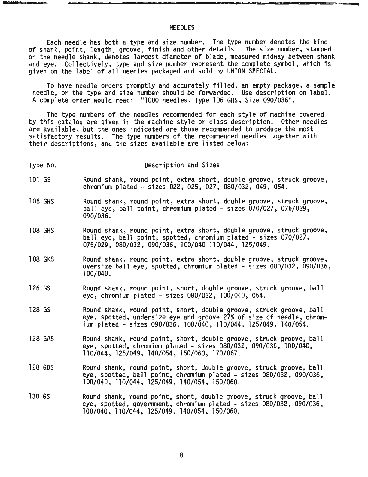
NEEDLES
Each
needle
has
both a type
of shank, point, length, groove,
on
the needle shank, denotes
and
eye.
given
To
Collectively,
on
the label
have
needle orders promptly
of
needle, or the type
A complete order
The
type
by
this
catalog are given in the
are
available,
satisfactory
their
Type
101
descriptions,
No.
GS
would
numbers
but the
results.
and
Round
chromium
106
GHS
Round
ball eye, ball
all
and
of
ones
The
shank,
shank,
largest
type
and
needles packaged
size
number
read: 111000
the needles
indicated are those
type
the sizes available are
round
plated - sizes 022, 025, 027, 080/032, 049, 054.
round
point,
090/036.
and
size
finish
and
diameter of blade,
size
number
and
accurately
should
needles,
recommended
machine
numbers
style
of the
Description
point,
point,
extra
extra
chromium
number.
other
The
type
details.
measured
number
The
size
midway
denotes the kind
represent the complete symbol,
and
sold
be
forwarded.
Type
or
recommended
and
short,
short,
plated -
by
UNION
filled,
106
GHS,
for
each
class
style
description. Other needles
recorrnnended
listed
below:
Sizes
double groove, struck groove,
double groove, struck groove,
sizes
SPECIAL.
an
empty
Use
description
Size 090/036
of
machine
to produce the
needles together with
070/027, 075/029,
number,
stamped
between
which
package, a
on
11
•
covered
most
shank
is
sample
label.
108
108
126
128
128
128
130
GHS
GKS
GS
GS
GAS
GBS
GS
Round
ball eye, ball point, spotted,
shank,
round
point,
extra
short,
chromium
double groove, struck groove,
plated -
sizes
075/029, 080/032, 090/036, 100/040 110/044, 125/049.
Round
oversize ball eye, spotted,
shank,
round
point,
extra
chromium
short,
double groove, struck groove,
plated - sizes 080/032, 090/036,
100/040.
Round
eye,
Round
eye, spotted, undersize
ium
Round
eye, spotted,
shank,
chromium
shank,
round
point,
short,
double groove, struck groove, ball
plated - sizes 080/032, 100/040,
round
point,
eye
short,
and
double groove, struck groove, ball
groove
27%
of
054.
size
of needle,
plated - sizes 090/036, 100/040, 110/044, 125/049, 140/054.
shank,
round
point,
chromium
short,
plated -
double groove, struck groove, ball
sizes
080/032, 090/036, 100/040,
110/044, 125/049, 140/054, 150/060, 170/067.
Round
eye, spotted, ball point,
shank,
round
point,
short,
double groove, struck groove, ball
chromium
plated -
sizes
080/032, 090/036,
100/040, 110/044, 125/049, 140/054, 150/060.
Round
eye, spotted, government,
shank,
round
point,
short,
double groove, struck groove, ball
chromium
plated - sizes 080/032, 090/036,
100/040, 110/044, 125/049, 140/054, 150/060.
070/027,
chrom-
8
Page 9

NEEDLES
(Continued)
Type
143
147
No.
GS
GKS
Round
shank,
spotted,
Round
shank,
chromium
Description
round
point,
plated - sizes 140/054, 150/060, 170/067, 230/090.
round
point, long, double groove, struck groove, oversize ball eye, spotted, short point, standard
chromium
Selection of proper needle size
plated - sizes 090/036, 100/040, 110/044, 125/049, 140/054.
is
Thread should pass freely through needle
formati,'on.
LUBRICATION
Use a straight
degrees
F.
Before operating,
plug screw
with
is
line
needle
though
oil,
check
reached,
marked 11FULL
registers
the
machine
gauge needle
is
recommended
operating,
to
the
to
"FULL"
This
(A,
gauge
registers
be
mark.
mineral oil with a Saybolt viscosity of
is
equivalent to
Fig. 1).
gauge
on
(B).
needle will
11
•
Oil
black
can
to
always
sure
machine
CAUTION:
fill
machine
While
When
must
line
be
operated safely
in the
check
Union
with
filling
machine
proper oil level
register
be
added
marked
on
when
"LOW'.
"OPERATE"
oil
level before
is
filled
DO
NOT
over
machine.
and
Sizes
No.
2 bag, double groove, struck groove,
eye
and
grooves,
determined
eye
in order to
by
size of the thread used.
produce a good
90
to
125
seconds
stitch
Special Corporation Specification
oil
at
black
gauge
Al-
when
zone,
with
it
oil
fill
No.
at
175.
100
To
drain
er
crank
must
be
chamber
changed
minimize wear.
On
new
machines, or a
for
an
extended period of time; lubricate
as follows:
Remove
rectly
place
proper
proper
damage
oil
head
level.
lubrication
which
head
needle bar link
cover
bution.
oil,
remove
cover
every
on
2000
cover, clean.out
and
fill
Run
machine
of
components
may
occur
from
plug
back
screw
of
machine.
(C), or
operating hours to
machine
and
machine
at
out of service
lint,
needle bar.
with
low
RPM
to ensure
oil
then
preventing
lack of
oil
distri-
9
low-
Oil
machine
di-
Re-
to
any
Fig. 1
Page 10

FIii main reservoir
here.
CAUTION:
before
Machine
before
FIii
oll
starting.
has
been
shipping.
reservoir
drained
full
mark
on gauge.
Fig. 2
FOR
Oil
has
been
drained
filled
needle of
lubricated
before
gauge
and
starting
registers
no
oiling other than
Refer to instructions
THREADING
ALL
STYLES
from
EXCEPT
machine
to operate. Maintain oil level in
on
the black
under 11LUBRICATION
AND
OILING
56300
E,F,G,N,R,U,X,AH
before shipping
line
marked
keeping
11
the
and
"CHANGING
DIAGRAM
"LOW".
main
information.
AH
Thread
and
AL.
machine
as
illustrated
above
for
10
all
Styles except
and
the reservoir
"OPERATE"
Machine
reservoir
STITCH
and
AL
zone;
is
filled
LENGTH"
56300
E,F,G,N,R,U,X,
must
add
be
oil
when
automatically
is
necessary.
for additional
Page 11

FIii main reservoir
here.
CAUTION:
before
Machine
before
Fill
oll
starting.
has
been
shipping.
reservoir
drained
CAUTION: Be sure looper connection Is
FIii reservoir
full mark on
up
before
to
gauge.
sewing.
Fig.
2A
FOR
STYLES
Oil
has
been
filled
before
needle of
lubricated
starting
gauge
and
drained
registers
no
oiling other than
from
to operate. Maintain oil level in 110PERATE
on
Refer to instructions under
THREADING
machine
the black
11
LUBRICATION
56300
keeping
AND
OILING
DIAGRAM
E,F,G,N,R,U,X,AH
before shipping
line
marked 11LOW
the
11
and
main
"CHANGING
and
11
reservoir
information.
Thread
machine
as
illustrated
above
for Styles
11
56300
and
AL
the reservoir
•
Machine
11
zone;
is
filled
STITCH
LENGTH"
E,F,G,N,R,U,X,AH
must
add
be
oil
when
automatically
is
necessary.
for additional
and
AL.
Page 12

ADJUSTING
INSTRUCTIONS
NOTE:
Instructions
machine,
of
handwheel
the
right
rotates counterclockwise, in operating direction;
end
stating
are
given
of
machine.
direction or location,
relative
OIL
To
recalibrate oil
- Place
Remove
-
machine
plug
upright
screw
gauge,
(C,
follow instructions in sequence
on
a level surface.
Fig.
1)
and
voir.
-
Remove
-
Fill
-
Loosen
registers
lower
crank
chamber
reservoir until
locknut
on
(E)
and
the black
cover
oil
is
even
rotate calibrating
line
marked 11LOW
- Tighten locknut {E), then replace
- Fill
machine
with oil until
gauge
such
to operator's position
GAUGE
tip
on
with
plug
needle
CALIBRATION
machine
back
of
machine.
bottom
11
screw
of
screw
•
(C)
registers
forward
knee
(F)
as
and
on
as
right,
at
as
to drain
left,
the
listed:
all
press shaft
required until
lower
crank
black line
front or rear
machine.
when
viewed
oil
bushing
The
from
(D).
gauge
chamber
cover.
marked 11FULL
from
reser-
needle
11
•
Fig. 3
Fig. 4
A
NEEDLE
(TWO
AND
Insert a new
size required).
needle bar
(A,
BAR
THREE
NEEDLE
set
Turn
Fig.
3)
ALIGNMENT
MACHINES)
of needles (type
handwheel
down
to bring
to ensure
needles center in needle holes of throat
plate
be
allowing needle bar to
ed. Tighten
as
shown
made
by
SYNCHRONIZING
in Fig.
loosening
clamp
screw.
LOOPER
3.
screw
be
AND
Adjustment
(B)
slightly,
turned
NEEDLE
as
MOTIONS
requir-
Insert looper into the looper rocker,
it
all
the
way
down
and
pushing
screw
handwheel
against
flat
on
in operating direction until
the point of the looper
to the
the
the
looper point
wheel
point
is
(See
left,
right
eye
of the needle with respect to the
is
even
needle (B).
(See
Fig. 5).
with the
in the reverse direction until the
of
looper again
even
with the
Fig. 5).
left
If
the height of the
shank
(A,
Note
the height of
Turn
moving
side of right needle
tighten
of looper.
Fig.
4)
moving
left
side of
the
hand-
to the
left,
eye
the needle with respect to the looper point
are the
synchronized - a variation of
(.127mm)
same,
is
allowable.
looper
and
needle
motions
.005
inch
12
and
that
can
Turn
of
are
Page 13

SYNCHRONIZING
If
the distance
point of
is
turned in the operating direction, the looper
drive
slightly
wards
NOTE:
the
lever
towards the
the
front
The
1/64 inch
Fig. 5
from
the
looper
rocker
is
greater
shaft
rear.
acts the reverse.
(.4mm)
is
for final
eye
will
LOOPER
AND
of the needle to the
when
have
Moving
dimension
setting
the
handwheel
to
be
the
shaft
shown
of needle
bar height.
NEEDLE
moved
to-
in
MOTIONS
(Continued)
For
these
J
1/84'
(.4mm)
-r
Proper
SYNCHRONIZATION of
Looper
two
1Hl
& Needle
Dimensions
--==-
in
OPERATING
Direction
will
Looper
FRONT of
REVERSE
Direction
be
the
Needle
In
same
in
Adjust looper drive rocker lever
Loosen
drive
Union
lever
Special
threaded
er
shaft through the center of
usting screw (E).
required
chronization. Tighten
and
remove
shaft.
thrust
adjusting
(7cm/kg);re-tighten lock nut
With
its
travel,
line
of
ing using
Classes except
21227
21227
looper
gauge
gauge
CX-56
CX-64
lever
(B)
should locate against the
looper rocker
sary,
drive
(D).
loosen
lever
If
checked with a scale.
centerline
which
should
Classes except
be
a 3 5/8 inch
should
be
extreme
screw
(D).
into
to
position
(C,
Fig.
A
rod
Screw
No.
the looper drive lever rock-
Tap
or pull
shaft
screw
rod
or
screw
Loosen
looper
right
gauge
lock nut
check
screw
at
location
(E)
extreme
looper connecting
No.
21227
56700
for Style
for Style
stud
(A,
which
56700
56700
Fig.
over threaded stud.
cone
clamp
(E)
gauge
(C).
screw
as
required
is
not available,
"X"
of stud
be
3 9/16 inch
right
end
(A)
to centerline
4 1/16 inch
56700.
(92.
Style
1nm)
(90.6mm)
of
travel.
4)
in looper
of
.146-40 thd.
22870 A can
for proper syn-
(C)
used
(F)
to position
and
to 6 in.
(F)
right
of
the center-
ex
for
uses
J-56
J-64.
6)
and
If
adjustment
(D), reposition looper
and
dimension
(103.2mm)
56700
and
Style
shaft
as
or
be
thrust
slightly
adj-
as
securely
TORQUE
lbs.
securely.
end
of
rod
bear-
all
gauge
and
No.
No.
Remove
nut
place hole in
The
left
end
RIGHT
side of
is
retighten
setting
is
of
can
from
cone
for
J-56 should
56700
J-64
with looper
follows:
from
of
necesscrew
be
(C)
all
at
Fig. 5
Fig. 6
LOOPER
ified.
(A,
Fig. 7)
Insert a new
If
the looper ga_
so
needle, type
the distance
looper is 5/32 inch
SETTINGS
uge
(4.0mm),
and
size
as
spec-
is
5/32 inch (4.0nm), for example,
from
the center
when
the looper
of
the needle
is
at
its
farthest
13
Fig. 7
set
the looper
(B)
to the point of the
position to the
right.
Page 14

LOOPER
SEITINGS
(Continued)
Looper
On
machines
two
gauge
needle
set
No.
21225-5/32
machines
set
the middle looper to the middle needle,
Refer to chart for needle
ment
is
ing
rod
(4.0mm)
left
ball
required, loosen nut
(F), turn the connecting
dimension. Retighten both nuts,
joint
is
in
vertical
Machine
Styles
56200
56200
56200
56200
56200
56300
56300
56300
56400
56400
56500
56500
56700
56900
56900
56900
56900
H
K,R
L
S
W,
56300
W,AL
E,F,G,N,R,
U,X,AH
H
M
D
P,R,S,T,W,X
A,B,C,U
J,R
J
H
J
P
R
Needle
101
106
126
108
128
128
143
126
106
106
130
128
108
128
147
147
147
(C)
the
Type,
(D)
Type
GS
GLS
GS
GHS
GAS
GBS
GS
GS
GHS
GHS
GS
GS
GKS
GAS
GKS
GKS
GS
can
be
back
looper to the
looper
(it
has a left
rod
forward or
position
used
advantageously in
right
gauge
setting
hand
backward
first
and
nut (E), then nut
does
not bind
Looper
Setting
Inch
1/8
1/8
Inch
5/32
1/8
5/32
5/32
5/32
5/32
1/8
1/8
5/32
5/32
1/8
5/32
7/32
5/32
7/32
Inch
Inch
Inch
Inch
Inch
Inch
Inch
Inch
Inch
Inch
Inch
Inch
Inch
Inch
Inch
making
needle
when
and
looper
thread)
and
setting
gauge
and
on
the looper gauge.
nut
to obtain the 5/32 inch
(D).
after
Gauge
(3.2mm)
(3.2mm)
(4.0mm)
(3.2mm)
(4.0mm)
(4.0mm)
(4.0mm)
(4.0mm)
(3.2mm)
(3.2mm)
(4.0mm)
(4.0mm)
(3.2mm)
(4.0ITITl)
{5.6mm)
(4.0ITITl)
(5.6mm)
adjustment.
this
adjustment.
three needle
number.
(E)
on
Make
Looper
If
connectsure the
Gauge
Number
21225-1/8
21225-1/8
21225-5/32
21225-1/8
21225-5/32
21225-5/32
21225-5/32
21225-5/32
21225-1/8
21225-1/8
21225-5/32
21225-5/32
21225-1/8
21225-5/32
21225-7/32
21225-5/32
21225-7/32
adj-
point
The
(A,
Fig. 8
looper
Fig.
is
8)
set
correctly
clears
and
wise
the
If
turn stop
sets
if,
as
rear
of
needle
adjustment
screw
the looper to the
wise acts the reverse.
this
adjustment
setting
should
flecting
needles
should
sure
is
obtained
On
Style
be
set
as
On
the
and
exist
on
the looper
56200
to barely contact the
looper
two
loopers.
without
looper in looper rocker,
feed
setting.
it
moves
is
necessary, loosen lock screw
(H)
to the
(B)
by
.002 inch (.05lmm).
as
required. Turning stop
rear
Holding
may
prove
and
recheck the adjustment.
W,
looper needle guard (attached to looper)
moves
and
three needle machines,
at
to
The
same
any
adjustment, other than applying pres-
front or
so
looper to the
helpful. Tighten lock
left.
looper - needle relationship
back
as to get the proper
left
and
behind the needle,
turning
front
of needle without de-
insert
of blade, while
(G,
screw
it
counterclock-
front
while
screw
·
the other
clamping
in-line-of-
its
Fig.
clock-
making
when
7)
14
Page 15

the
The
top
height of the needle
of
its
eye
is
1/64 inch (
is
correct
.4mm)
NEEDLE
BAR
when
below
the underside of the looper, with the looper
point
as
flush
shown
C the top of the needle eyes should
with the underside of the looper
looper
point
the needle.
loosen screw
(A)
up
or
care should
bar
either
the 1
oope
with
the
in Fig. 5.
is
flush with the
If
adjustment
(8,
Fig. 3)
down
as
be
taken not to disturb alignment of needle bar
up
or
down.
rs.
left
On
Styles
and
required
The
side of the needle
56500
left
is
necessary, Fig. 9
move
and
retighten screw.
A,
Band
be
even
when
the
side of
needle bar
descending needles
FEED
DOG
SETTINGS
HEIGHT
On
two
must
be
and
three needle machines,
when
moving
deflected alike
the needle
on
the
back
of
plate
feed
travel,
of
Feed
travel
(B)
dog
with
set
tips
(A,
Fig.
equal
clearance
to desired
of feed
9)
dog
should
of a tooth or approximate.ly
plate
support feed
secures feed
extend
"Grip
feed
of the top
and
On
Styles
1/32
Feed"
dog
parallel to
dog
after
dog
in position.
56300
inch
N,U,X,AH
(.8mm)
presser foot feed
left
and
to
right,
bottom
same.
screw
above
and
feeds should
point.
Parallel
clockwise
ly
set,
retighten nut
Right
made
and
by
loosening
slightly
feed rocker shaft
then
sure
not bind
retighten
that
after
adjustment
to
lower
to
front of feed
left
adjustment
screws
move
feed rocker
(C)
screws.
feed rocker
adjustment.
can
(A).
(A,
as
required,
Check
arm
(D)
be
centered in throat
on
all
stitch
sides
length.
and
ends
At
highest point
with
teeth should extend the depth
3/64 inch
Screw
(D)
has
the
the throat plate
dog
in-line-of-feed the
be
made
dog,
can
(1.2mm)
(C)
should
been
tips
of the teeth
must
line
match
by
loosening nut
above
be
loosened
set
which
throat
to
must
and
the
with the
last
lower
teeth
tooth point to
counterclockwise acts the reverse.
be
Fig. 11)
(B)
on
to endoes
(A,
Fig.
10)
and
Fig.
turn
10
screw
When
(B)
proper-
Forward
of feed
dog
loosening nut
feed rocker (B)
or rearward centering
can
be
accomplished
(E,
Fig.
11),
move
as
required
and
by
re-
tighten nut.
15
Fig.
11
Page 16
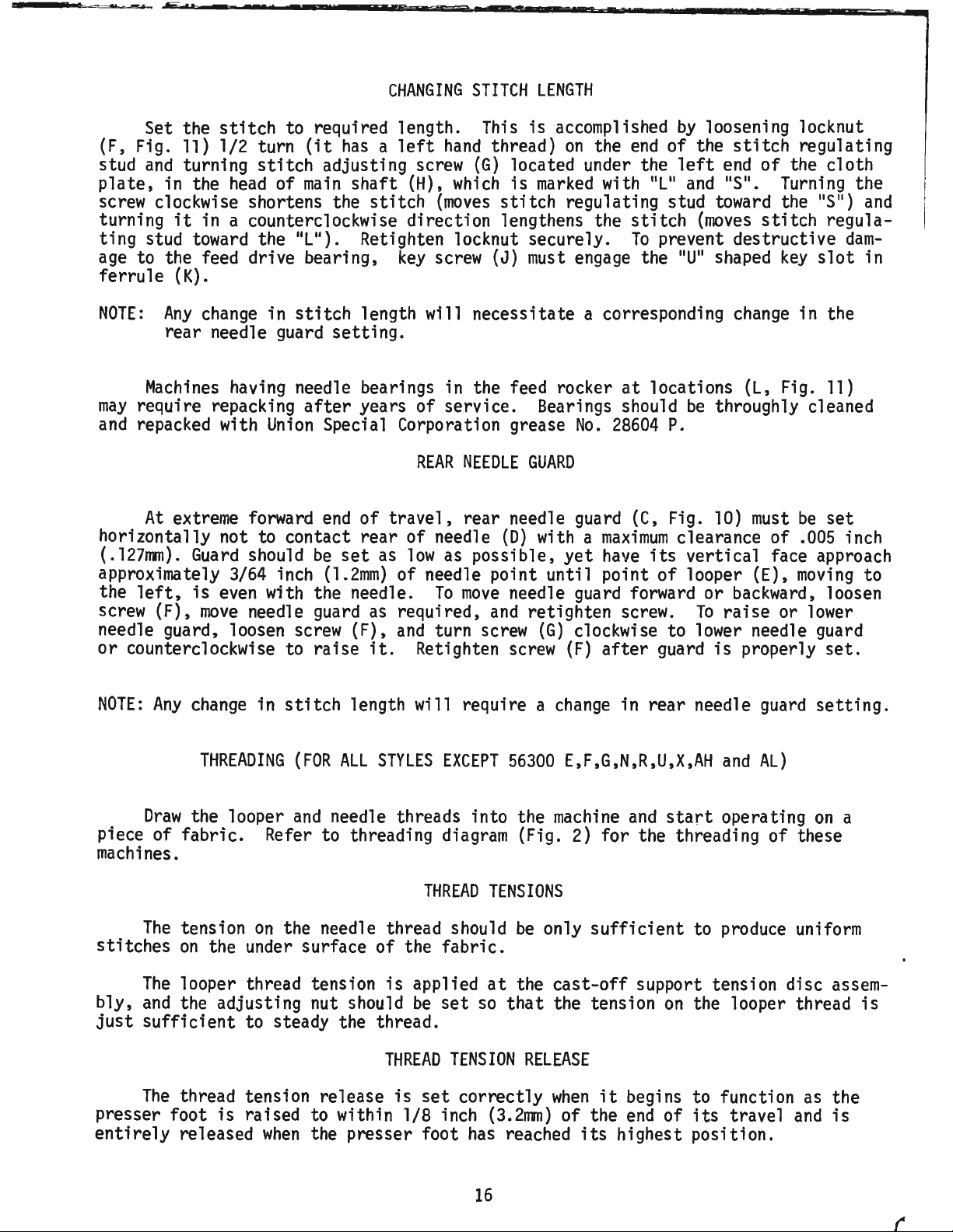
CHANGING
STITCH
LENGTH
Set the
(F, Fig.
and
stud
plate,
screw
in the
clockwise shortens the
turning
ting stud
age
to the feed drive bearing,
ferrule
NOTE:
Any
rear needle
Machines
may
require repacking
and
repacked with
At
extreme
stitch
11)
1/2 turn
turning
head
it
in a counterclockwise direction lengthens the
toward
to required length.
(it
has a left
stitch
of
main
adjusting
shaft
stitch
the 11L
11
).
Retighten locknut securely.
screw
(H),
key
hand
(G)
which
(moves
screw
(K).
change
in
having
Union
forward
stitch
guard
length will necessitate a corresponding
setting.
needle bearings in the feed rocker
after
years of service. Bearings should
Special Corporation grease
end
of
REAR
travel,
NEEDLE
rear needle
horizontally not to contact rear of needle
(.12711111).
approximately 3/64 inch
left,
the
screw
needle guard, loosen
or
counterclockwise to raise
(F),
Guard
is
even
move
should
be
set
(1.2mm)
with the needle.
needle
guard
screw
as
(F),
it.
as
low
as possible,
of needle point until point
To
move
required,
and
turn
Retighten
This
is
thread)
accomplished
on
the
located under the
is
marked
stitch
(J)
regulating stud
must
engage
No.
GUARD
guard
(D)
with a
maximum
yet
needle
and
screw
screw
guard
retighten screw.
(G)
clockwise to
(F)
after
end
with 11L
stitch
To
prevent destructive
the 11U
at
locations
28604
(C,
have
its
of
forward or
guard
by
loosening locknut
of the
left
11
and 11S
stitch
end
11
toward
(moves
11
shaped
change
(L,
be
throughly cleaned
regulating
of the cloth
•
Turning
the 11S
stitch
key
in the
Fig.
11
regula-
slot
11)
P.
Fig.
10)
must
clearance of
be
set
.005
vertical face approach
looper (E),
backward,
To
raise
lower
is
properly
moving
loosen
or
lower
needle guard
set.
the
)
and
dam-
in
inch
to
NOTE:
Any
Draw
change
in
stitch
THREADING
the looper
length will require a
(FOR
ALL
STYLES
and
needle threads into the
piece of fabric. Refer to threading
machines.
The
stitches
The
bly,
and
just
sufficient
tension
on
the under surface of the fabric.
looper thread tension
the adjusting nut should
on
the needle thread should
is
applied
be
to steady the thread.
THREAD
The
thread tension release
presser foot
entirely
released
is
raised to within 1/8 inch
when
the presser foot
is
EXCEPT
diagram
THREAD
TENSIONS
at
set
so
TENSION
set
correctly
(3.2rrm)
has
change
56300
E,F,G,N,R,U,X,AH
machine
(Fig.
be
only
the
cast-off
that
the tension
RELEASE
when
of the
reached
in rear needle
and
start
2)
for the threading of these
sufficient
to
guard
and
AL)
operating
produce
support tension disc
on
the looper thread
it
begins to function
end
of
its
travel
its
highest position.
setting.
on
a
uniform
assem-
as
the
and
is
is
16
Page 17

If
adjustment
screw
tension
adjustment there should
(A,
Fig. 12), located
disc
separator
is
required, loosen tension release lever
THREAD
as
required. Retighten screw. After
be
at
no
binding
TENSION
the
back
at
PRESSER
RELEASE
of
machine
any
BAR
(Continued)
point.
HEIGHT
and
move
A
'
Height of presser bar
sser
clearance
guide
casting
lying
stroke.
er
ion
and
so
to feed
on
sure, counterclockwise acts the reverse.
(B,
Fig.
foot
and
retighten
that
the
(FOR
foot
Adjustment
Regulate presser spring regulating
can
12).
between
(B,
Fig.
when
flat
on
Loosen
down
guide
it
exerts only
the
fabric.
NEEDLE
ALL
be
removed
There
foot
throat plate with feed
on
as
screw.
work
THREAD
STYLES
should
lower
13)
and
lifter
can
be
screw
throat
Turning
(C,
required to
uniformly
TAKE-UP
EXCEPT
(A,
Fig.
13)
by
depressing foot
be
approximately 1/16 inch
surface of presser bar connection
bottom
lever
made
plate,
enough
it
surface of
is
released
dog
by
turning
Fig.
13)
position presser bar connect-
attain
PRESSER
pressure
when a slight
clockwise increases the pres-
WIRE
56300
E,F,G,N,R,U,X,AH
handwheel
and
while holding press-
specified clearance
on
AND
is
correct
lifter
head
and
below
FOOT
PRESSURE
screw
the presser foot
tension
FRAME
EYELET
when
lever
opeining in
presser foot
throat
to position needle bar
(A,
Fig. 14)
is
and
pre-
(1.6mm)
plate.
placed
AL)
and
bed
Fig.
at
12
bottom
of
Set needle thread take-up wire
its
upper surface
needle bar thread eyelet
its
downward
needle thread loop, or raise
needle thread
3/4 inch
on
all
Styles except
56900
5/8 inch
and
l inch
NOTE:
for
threaded.
H,
on
Style
(25.4mm)
For
56300
see
56300
Refer to threading
the
manner
stroke.
(19.0mm)
J,
P
(15.9mm)
56200
the
E,F,G,N,R,U,X,AH
the following paragraphs.
THREADING
E,F,G,N,R,U,X,AH
is
even
frame
and
above
in
eyelet
above
on
R the eyelet
above
H the eyelet
above
setting
(FOR
which
with the
(C)
Lower
the attaching
Styles
the attaching
the attaching screw.
STYLES
diagram
these
(B,
Fig.
top
of the holes in
when
this
it
(D)
on
and
needle bar
setting
for a larger loop. Set
so
that
56500
is
to
is
to
Styles
and
AL,
AL)
(Fig.
machines
for a smaller
the eyelet hole
screw
J,
be
set
screw
be
set
2A)
are
14),
has
completed
so
that
is
Fig.
14
Fig.
13
17
Page 18

NEEDLE
FOR
THREAD
(STYLES
TAKE-UP
56300
E,F,G,N,R,U,X,AH
WIRE
AND
FRAME
EYELET
and
AL)
Fig.
14A
With
Fig.
14A)
needle bar
so
its
at
the top of
lower extended surface
needle lever thread eyelet hole
vertical surfaces
(See
Fig.
14A).
left
of looper thread take-up (B),
to a
(light).
adjusting plate
only, with nut (E), balance the
inches
thread
inch
Use a sample
needle thread tension,
toward 11L
and
These
are equipped with additional thread handling
___:.i.,j~-----...__,
trol
parts,
ing sequence should
in the following
its
stroke,
is
and
3/4 inch
Set looper thread guide eyelet
outer surface
set
needle thread take-up wire
1 7/16 inch
(19.0mm)
is
3/4 inch
(36.5mm)
above
across the centerlines of
(A,
(19.0rrm)
(See
Fig. 15).
Adjust looper thread tension with nut
minimum
(152.4mm)
is
(25.4mm)
toward 11T
required for controlling the looper thread
Set the thread index eyelet
(D).
Changing
the needle thread tension
stitch
of
sewn
seam
are raveled back, the needle
(C)
so
approximately as long as the looper thread.
difference in lengths
of
the material to
11
to obtain a looser
11
to obtain a
move
thread index eyelet
seam
tighter
is
permissible.
be
sewn.
(longer needle loops)
seam.
Fig.
15
machine
so
the adjust-
manner:
centerline of
Fig.
15)
from
the
(B,
at 113
that
Fig.
11
when
Maintaining
(C)
styles
and
be
(A,
so
its
left
14A)
on
the
6
NOTE:
up
conmade
its
side
Al
this
to
Fig.
16
FEEDING
Remove
spring. Adjust
bar guide
clearance
(C), yet
link
(E)
so
(D)
when
on
stop screw.
PRESSER
FOOT
the presser spring regulator
long
stop
(B)
against
between
that
guide
bed
the guide
is
foot treadle
18
and
presser
screw
casting
pulled
is
(A,
Fig.
16)
in presser
as
required to ensure a
and
top
of
presser bar bushing
up
quickly
by
lifter
activated. Tighten lock nut
lever
Page 19

As
a preliminary
presser
(15.9mm),
foot
throat
regulator
foot
(See
to
presser bar.
plate
nut
so
Fig. 17).
and
{A,
foot bottom line
FEEDING
setting,
the distance
Assemble
With
presser foot resting
feed
dog
down,
Fig.
17)
until the
up
with the centerline of needle,
PRESSER
FOOT
adjust spring regulator nut
from
the top of spring
the feeding presser
press
down
marks
on
spring
on
presser
while keeping the needle in the center of needle
slot,
guide
presser
tighten
to
set
the presser bar,
bar guide
screw
is
resting
(D)
securing presser bar
making
sure stop
on
the
bed
screw
casting.
(Continued)
(B)
to the
on
in
(A,
Fig.
yoke
17)
(C)
on
feeding
is
5/8 inch
Replace presser spring
ulator.
down
until
Turn
presser bar spring regulator
the thread portion
casting.
NOTE:
lationship
probably
guide
ing
throat
less
the
Any
change
to the
was
set
When
plate,
means
not seated against
screw.
the presser foot
that
the foot should
than 1/64 inch
factory,
can
be
Presser foot
resting
on
When
the bare throat
the presser foot
spring bottoms, the
er
bar should not
and
presser spring reg-
screw
is
level with the
in the alignment of needle in
marks
on
the presser foot
the stop
screw
bed
is
(.4mm).
The
readjusted
bottom
of the presser bar
c3sting before lock-
lifted
move
if
off
the bare Fig.
back
only
slightly,
stop
screw
{E,
necessary, should
CHECK
at
back
of needle
slot
should cover
plate.
back
lift
bottom
of the needle
before the feeding foot spring bottoms.
is
raised
slot
by
should
head
re-
-Fig.
17)
this
material
clear
on
the yoke,
dimension
most
of throat plate land
so
that
the needle.
17
which
become
is
set
changed.
the feeding foot
The
main
press-
at
when
The
purpose of the feeding foot
the
same
amount
without pulling
on
the feeding foot spring usually gives a
pull.
pressure will tend to feed the
centimeter/kilograms.
Reducing
Torque
this
pressure will tend to feed the top ply
bottom
specifications given in
All
straps
(22-24cm/kg) unless otherwise noted.
specifications
must
be
secured
as
Special torque specifications for connecting rods,
parts
illustrations.
is
to
the
bottom
good
ply
TORQUE
REQUIREMENTS
this
and
eccentrics
All
tightly
make
the top
ply.
The
matching of
more.
catalog are
nuts,
as
possible, unless otherwise noted.
measured
must
bolts,
be
links,
19
and
bottom
5/8 inch
piles
and
more.
in
tightened to
screws,
etc
screws,
ply of cloth feed
{15.9mm)
setting
a strong feeding
Increasing
this
inch-pounds or
19-21
in.
. , without torque
etc.,
are
shown
on
lbs.
on
Page 20

SPECIAL
INSTRUCTIONS
Fig.
18
When
adjusting needle lever or replac-
ing
related
sequence
1.
as
Install 110
needle lever stud
NEEDLE
parts,
listed:
11
rings
follow instructions in
LEVER
(A,
Fig.
(B)
and
(C).
2.
With
positioned properly;
needle lever
(D)
in
insert
through hole in needle lever until
shoulder contacts the needle lever
the
word 11UP
position.
exists
3.
stud
top of
Install
(B)
machine
pression
push
ring
machine
11
on
While
stud
making
is
in the needle bar
with the front
bed.
temper
cups
and
load ring
(F)
onto stud (B), then
cups
through
bed.
sure
set
18)
onto
thrust
machine
collar
and
stud (B)
its
and
in the upright
no
binding
link,
(E)
secure
screw
and
opening
in
com-
in
•
Fig. 19
.045"
Fig.
( 1.14mm)
20
ALIGNING
4.
Install
being careful not to
Compress
ing
against stud
position using the rear
of
5.
To
pression,
and
Thrust
-
ring in reverse order, then tighten
set
6.
With
position,
its
stud.
their
of
ricating
MAINSHAFT
TO
thrust
collar
(C)
damage
screw
components
(G)
until
{B).
together
washer
Secure stud
set
bed.
check
loosen rear
.007
temper
remove
set
collar
(C)
inch (.08 -
load ring for proper
screw
(G)
screw
should spring out
.18mm).
screw.
in
11
on
stud
bearing
oil
supply hole
and
stud are secured in
indented 11UP
install
hook
sets
When
hook
proper positions, the proper
oil
will
be
channeled to stud for lub-
needle lever
(D).
CRANKSHAFT
onto stud
11011
ring.
by
tighten-
(H)
bottoms
(B)
screw
from
stud (B)
in
top
of
Compress
(B)
in
oiler
(J)
(K)
(B)
in
in top
com-
bed.
.003
load
rear
upright
so
of
amount
As
viewed
couplings
must
align with the
positioned
head
and
must
the
looking
down
from
rear
of
machine, spot
align with the spots in the looper drive crank
laterally
bed
casting as
flats
with
on
crankshaft
.045
inch
shown
(1.14mm)
in Fig.
(D)
20.
and
mainshaft (E). Mainshaft
clearance
20
screws
between
(A,
(B)
the
Fig.
and
right
19)
set
side of
in
the
screws
must
(C)
be
its
Page 21

ALIGNING
MAINSHAFT
TO
CRANKSHAFT
(Continued)
Looper
(.8mm)
tings are
ing sequence for best performance.
screws
__
21
screws
que
24cm/kg), then, torque screws
to
located in the
positioned with
cut
the
It
be
in
to position
screws.
clearance
Tighten spot
in.
screws
19-21
The
out in the
left
has
elongated
adjusted
top
of
drive
made,
(C) temporarily, to the crankshaft
lbs.
(A)
(22-24cm/kg).
and
(F)
in. lbs.
oil
drip plate
as
possible without touching.
by
the
as
Crank
between
it
is
screws
set
screws
to
19-21
(22 -24cm/kg).
oil
reservoir should
its
bed
casting,
mounting
loosening
oil
reservoir
required, retighten
(B,
Fig.
it
and
very
tip
important
(A)
temporarily, to the looper drive crank. Tighten
Loosen
(C).
in.
lbs.
(A,
Fig.
in the recessed
as
holes
(2)
screws
back
19)
mainshaft
spot
Re-tor-
(22
(A
and
21)
be
far to
and
can
(B)
cover
must
that
-
C)
be
positioned
(E)
as
shown
the couplings are tightened in the follow-
and
mainshaft.
laterally
in Fig.
Torque
with 1/32 inch
19.
Once
screws
these
(F)
to
set-
set
19
-
•
Fig.
21
21
Page 22
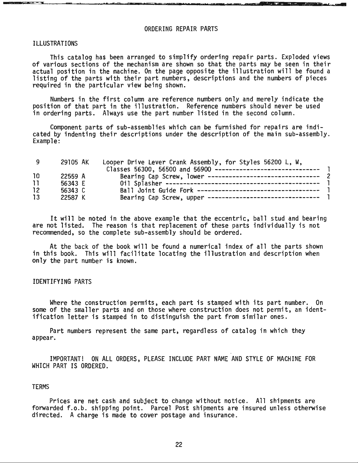
ILLUSTRATIONS
ORDERING
REPAIR
PARTS
This catalog
of
various sections
has
of
actual position in the
listing
required in the
position of
in ordering
cated
of the parts with
particular
Numbers
in the
that
part
parts.
Component
by
indenting
parts
first
Always
their
Example:
9
10
11
12
13
are not
It
29105
22559
56343
56343
22587
will
listed.
recommended,
AK
A
E
C
K
be
so
Looper
noted in the
The
the complete sub-assembly should
been
arranged to simplify ordering
the
mechanism
machine.
their
view
column
in the
of
sub-assemblies
illustration.
use
the
are
shown
On
the
page
part
numbers,
being
shown.
are reference
part
number
which
so
that
opposite the
descriptions
numbers
Reference
listed
can
be
only
numbers
in the
furnished for repairs are
the parts
descriptions under the description of the
Drive
Classes
Bearing
Oil
Ball
Bearing
reason
Lever
56300,
Cap
Crank
56500
Screw,
Assembly,
and
56900
for Styles
------------------------------
lower--------------------------------
Splasher--------------------------------------------
Joint
above
is
Guide
Cap
Screw,
example
that
replacement of these parts individually
Fork-----------------------------------
upper--------------------------------
that
the
eccentric,
be
ordered.
repair
parts.
may
illustration
and
the
numbers
and
merely indicate the
should never
second
main
56200
ball stud
Exploded
be
seen in
will
be
of
be
column.
sub-assembly.
L,
W,
and
views
their
found
pieces
used
indi-
bearing
is
not
a
1
2
1
1
1
At
the
back
in
this
book.
only the part
IDENTIFYING
Where
some
of the smaller parts
ification
Part
PARTS
the construction permits,
letter
numbers
of the
This
number
is
appear.
IMPORTANT!
WHICH
PART
IS
ON
ORDERED.
TERMS
Prices are net cash
forwarded
f.o.b.
shipping point. Parcel Post shipments are insured unless otherwise
directed. A charge
book
will
will
stamped
facilitate
is
known.
and
on
in to distinguish the
represent the
ALL
ORDERS,
and
subject to
is
made
to cover postage
be
found
locating the
each
those
same
where
part,
PLEASE
a numerical index of
illustration
part
is
stamped
construction
part
regardless
INCLUDE
change
PART
without notice.
and
insurance.
of
NAME
and
with
does
from
similar ones.
catalog in
AND
STYLE
all
the parts
description
its
part
number.
not permit,
which
OF
MACHINE
All
shipments are
an
they
shown
when
On
ident-
FOR
22
Page 23
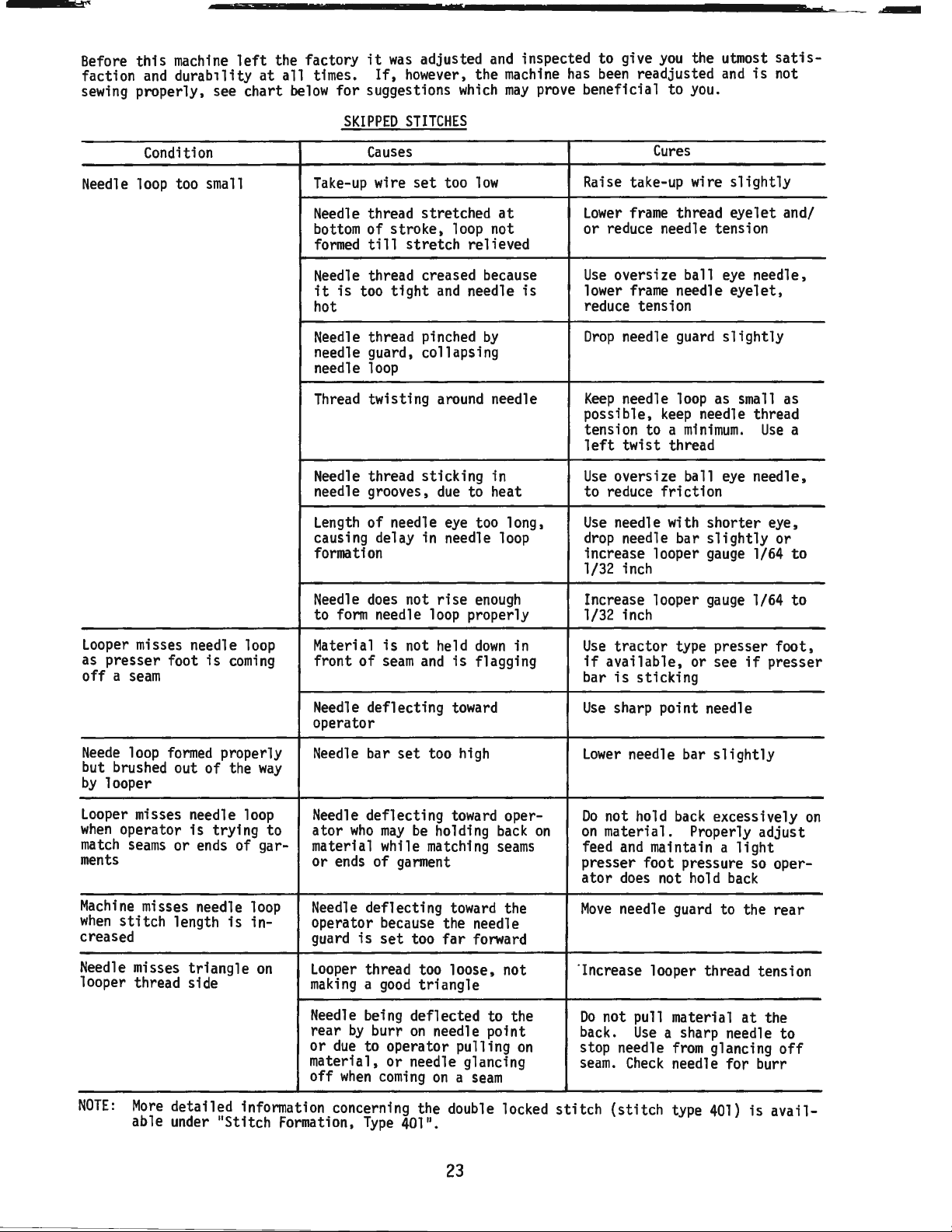
Before
faction
sewing
this
machine
and
durability
properly, see chart
left
at
the factory
all
times.
below
for suggestions
it
If,
was
adjusted
however,
and
the
which
inspected to give
machine
may
has
prove
been
beneficial to
you
the utmost
readjusted
you.
and
is
satisnot
Needle
Condition
loop
too
small
SKIPPED
Take-up
Needle
bottom
formed
Needle
it
is
hot
Needle
needle guard, collapsing
needle
Thread
Needle
needle grooves,
Length
causing delay in needle
formation
STITCHES
Causes
wire
set
thread stretched
of
stroke, loop not
till
stretch
thread creased because
too
tight
thread pinched
loop
twisting
thread sticking in
of needle
too
relieved
and
needle
around
due
to heat
eye
low
by
too long,
at
is
needle
loop
Cures
Raise
Lower
or reduce needle tension
Use
possible,
Use
to reduce
Use
drop
1/32 inch
take-up wire
frame
thread eyelet and/
oversize ball
lower
frame
reduce tension
Drop
needle
Keep
needle
tension to a
left
twist thread
oversize ball
needle with shorter eye,
needle bar
increase looper
needle eyelet,
guard
loop
keep
minimum.
friction
slightly
eye
needle,
slightly
as
small
needle thread
eye
needle,
slightly
gauge
1/64
Use
or
as
a
to
Looper
as
off a seam
Neede
but brushed out of the
by
Looper
when
match
ments
Machine
when
creased
Needle
looper thread
misses needle
presser foot
loop
formed
looper
misses needle
operator
seams
or
misses needle
stitch
length
misses
is
coming
properly
is
trying to
ends
of gar-
is
triangle
side
loop
way
loop
loop
in-
on
Needle
to
Material
front
Needle
operator
Needle
Needle
ator
material while
or
Needle
operator because the needle
guard
Looper
making a good
Needle
rear
or
material,
off
does
not
form
needle
is
of
seam
deflecting
bar
deflecting
who
may
ends
of
deflecting
is
set
thread too loose, not
being deflected to the
by
burr
due
to operator pulling
or
when
coming
rise
loop
not held
and
is
toward
set
too
high
toward
be
holding
matching
garment
toward
too
far
triangle
on
needle point
needle glancing
on a seam
enough
properly
down
flagging
operback
seams
the
forward
in
on
Increase looper
1/32 inch
Use
tractor
if
available, or see
bar
is
sticking
Use
sharp point needle
Lower
needle bar
Do
not
on
on
feed
presser foot pressure
ator
Move
"Increase looper thread tension
Do
back.
stop needle
seam.
hold
material.
and
maintain a
does
not
needle
not pull material
Use
Check
gauge
type presser
slightly
back
excessively
Properly adjust
hold
guard
a sharp needle to
from
glancing
needle for burr
1/64 to
foot,
if
presser
light
so
oper-
back
to the rear
at
the
off
on
NOTE:
More
detailed information concerning the
able
under
"Stitch Formation,
Type
401".
double
locked
stitch
23
(stitch
type
401)
is
avail-
Page 24

50
i
56
Page 25

Ref.
-1!9..:.
1
2
3
4
4A
5
6
6A
7
7A
8
9
9A
10
11
12
13
14
15
16
17
18
19
20
21
22
23
24
25
26
27
28
29
30
31
32
33
34
35
36
*37
*38
39
40
41
41A
42
43
44
45
46
47
48
49
50
51
52
53
54
55
56
57
58
59
60
61
62
63
64
65
66
67
68
69
*See
U,
X,
Page
AH
35
and
Part
...!i!!..:..
22829
21375
98
52
158
56391
52958
52958
21396
21396
22569
56782
22733
21396
11638
660-74
660-75
21396
660-73
21396
22569
56382
56382
22585
56393
7947
56393
51294
22513
660-342
35731
56958
605
22836
660-617
57
15438
57
43296
95
22889
539
51758
22848
20
56470
56370
51270
59493
666-214
56382
56382
22829
56480
51280
22839
56380
51280
660-313
87
22585
22524
56382
56382
22548
56382
56382
56382
87
56382
56382
22894
56382
22848
for
thumbscrew
AL.
AV
A
A
A
8
G
BP
AG
8
C
BR
M
AL
BK
C
N
D
C
R
A
8
A
WD
C
WB
A
8
A
K
J
J
J
A
G
H
D
E
AA
AB
Y
E
L
MAIN
FRAME,
THROAT
PLATE
SUPPORTS,
Screw
- - - - - - - - - - - - - - - - - - - - - - - - - - - - - - - - - - - - - - - - - 2
Guard
Belt
Screw
Looper
Looper
Looper
Looper
Looper
Needle
Felt
Screw,
Head
Plug
Needle
Nut
Connection
Coupling- - - - - - - - - - - - - - - - - - - - - - - - - - - - - - - - - - - - - - 1
Adapter - - - - - - - - - - - - - - - - - - - - - - - - - - - - - - - - - - - - - - 1
Oil
Needle
Screw,
Head
Gasket
Screw
Head
Nut
- - - - - - - - - - - - - - - - - - - - - - - - - - - - - - - - - - - - - - - - - - 1
Head
Screw
Screw
Lockwasher
Presser
Frame
Screw,
Screw
Needle
Nipper
Nipper
Nipper
Nipper
Plug
Adapter
Frame
56700
Frame
Screw
Washer ·-- - - - - - - - - - - - - - - - - - - - - - - - - - - - - - - - - - - - - - - 1
Needle
and
Needle
Needle
Base
Gasket- - - - - - - - - - - - - - - - - - - - - - - - - - - - - - - - - - - - - - - - - l
Looper
Screw
Throat Plate Support, for Styles
56500, 56700,
Screw,
Throat Plate Support, for Styles
AL
- - - - - - - - - - - - - - - - - - - - - - - - - - - - - - - - - - - - - - - - - - 1
Well
Screw,
Styles
Throat Plate
Screw
Screw
Oil
Reservoir
Gasket- - - - - - - - - - - - - - - - - - - - - - - - - - - - - - - - - - - - - - - - - 1
Screw
Crank
Gasket- - - - - - - - - - - - - - - - - - - - - - - - - - - - - - - - - - - - - - - - - 1
Oil
Reservoir
Screw
Oil
Drip
Oil
Drip
Screw
Gasket- - - - - - - - - - - - - - - - - - - - - - - - - - - - - - - - - - - - - - - - - l
Screw
adjustable
- - - - - - - - - - - - - - - - - - - - - - - - - - - - - - - - - - - - - - 1
- - - - - - - - - - - - - - - - - - - - - - - - - - - - - - - - - - - - - - - - - 3
Thread
Eyelet, for
Thread
Eyelet, for Class
Thread
Guard
Thread
Thread
Thread
Pad
for
Class
Cover,
for Styles
Screw
Thread
- - - - - - - - - - - - - - - - - - - - - - - - - - - - - - - - - - - - - - - - 1
Cup
- - - - - - - - - - - - - - - - - - - - - - - - - - - - - - - - - - - - - - 1
Thread
for
head
Cover,
for
- - - - - - - - - - - - - - - - - - - - - - - - - - - - - - - - - - - - - - - - 1
- - - - - - - - - - - - - - - - - - - - - - - - - - - - - - - - - - - - - - - - - 1
Oil
Tube
Oil
Tube
- - - - - - - - - - - - - - - - - - - - - - - - - - - - - - - - - - - - - - - - - 1
- - - - - - - - - - - - - - - - - - - - - - - - - - - - - - - - - - - - - - - - - 3
- - - - - - - - - - - - - - - - - - - - - - - - - - - - - - - - - - - - - - 1
Bar
Connection
Needle
for Styles
for
56958
Lever
Spring
Spring,
Spring
Spring Base, for Styles
Screw
and
Plug
Needle
J - - - - - - - - - - - - - - - - - - - - - - - - - - - - - - - - - - - - - - - 1
Needle
- - - - - - - - - - - - - - - - - - - - - - - - - - - Thread
56200
except Style
Thread
Thread
Oil
Pump
Felt-
Intake
Drive
- - - - - - - - - - - - - - - - - - - - - - - - - - - - - - - - - - 1
Eyelet, for single needle
Eyelet,
for
Lubricator, for Class
- - - - - - - - - - - - - - - - - - - - - - - - - - - - - - - - - - - - - 2
56900
- - - - - - - - - - - - - - - - - - - - - - - - - - - - - - - - 2
56400
- - - - - - - - - - - - - - - - - - - - - - - - - - - - - - - - - - - - 1
Lubricator
Oil
Sleeve - - - - - - - - - - - - - - - - - - - - - - - - - - - - - - - - - 1
Lubricator
cover - - - - - - - - - - - - - - - - - - - - - - - - - - - - - - - - - 2,3
all
Clamp
Mounting
Thread
8,
Eyelet Gasket - - - - - - - - - - - - - - - - - - - - - - - - - - - - - - 1
Screw,
for
Plate,
Screw
Screw
Thread
Thread
Take-up
Take-up
Take-up
Assembly-
Oil
Styles except
- - - - - - - - - - - - - - - - - - - - - - - - - - - - - - - - - - 1
Block
Guide
Eyelet, for Style
56200
s,
for Style
for Styles
Styles
for Styles
for take-up wire - - - - - - - - - - - - - - - - - - - - - - - - - 2
- - - - - - - - - - - - - - - - - - - - - - - - - - - - - - - - - - 1
Eyelet, for
Eyelet, for Style
Wire,
56200
Wire, for Styles
Wire,
- - - - - - - - - - - - - - - - - - - - - - - - - - - - - - - - l
- - - - - - - - - - - - - - - - - - - - - - - - - - - - - - - - - - - l
Shaft Reservoir
- - - - - - - - - - - - - - - - - - - - - - - - - - - - - - - - - - - - - - - - - 2
56900-
Dowel
Pin- - - - - - - - - - - - - - - - - - - - - - - - - - - - - - - - - - - - - 2
for
throat plate support - - - - - - - - - - - - - - - - - - - - - - - - - - - - 3
Dowel
Pin- - - - - - - - - - - - - - - - - - - - - - - - - - - - - - - - - - - - - 2
Nut-
- - - - - - - - - - - - - - - - - - - - - - - - - - - - - - - - - - - - - - - 3
for
throat
56300
H,
(See
- - - - - - - - - - - - - - - - - - - - - - - - - - - - - - - - - - - - - - - - - 3
- - - - - - - - - - - - - - - - - - - - - - - - - - - - - - - - - - - - - - - - - 8
- - - - - - - - - - - - - - - - - - - - - - - - - - - - - - - - - - - - - - - - - 4
Chamber
- - - - - - - - - - - - - - - - - - - - - - - - - - - - - - - - - - - - - - - - - 2
Top
Cover, lower- - - - - - - - - - - - - - - - - - - - - - - - - - - - - - - 1
Back
Plate- - - - - - - - - - - - - - - - - - - - - - - - - - - - - - - - - - - - - 1
Plate
- - - - - - - - - - - - - - - - - - - - - - - - - - - - - - - - - l
plate,
M,
AL-
- - - - - - - - - - - - - - - - - - - - - - - - - - - - - - - - 2
Pages
47, 49, 51, 55, 57, 59, 61, 63,
Cover
- - - - - - - - - - - - - - - - - - - - - - - - - - - - - - - - 1
Cover-
Clamping
Block
- - - - - - - - - - - - - - - - - - - - - - - - - - - - - - - - - - - - - - - - - 2
- - - - - - - - - - - - - - - - - - - - - - - - - - - - - - - - - - - - - - - - - 9
frame
needle thread eyelet
MISCELLANEOUS
~~~~
all
Classes except
56900
- - - - - - - - - - - - - - - - - - - - - - - - - 1
two
and
three needle
56900
R,
56700
J,
Reservoir, for Class
Reservoir Bracket, for Class
56400
COVERS
AND
OILING
PARTS
56900
- - - - - - - - - - - - - - - - - - 1
machines
- - - - - - - - - - - - - - - - - - - - - - - 1
56900
R,
- - - - - - - - - - - - - - - - - - - 1
machines
H,
56700
- - - - - - - - - - - - - - - - 1
J,
P,
R - - - - - - - - - - - - - - - 1
56900
- - - - - - - - - - - - - - - - 1
56900
- - - - - - - - - - - - 1
J,
56900
H,
J,
P, R-- - - - - - - - - 1
- - - - - - - - - - - - - - - - - - - - - - - - - - - - - 1
Plate - - - - - - - - - - - - - - - - - - - - - - - - - - 2
W;
56300
56900
56200
for
W - - - - - - - - - - - - - - - - - - - - - - - - - - - - 1
for Styles
Cover-
countersunk head, for Styles
56900
W,
J - - - - - - - - - - - - - - - - - - - - - - - - - 1
56200
s,
W;
56200
56200
all
Styles except
Style
J - - - - - - - - - - - - - - - - - - - - - 1
AL
- - - - - - - - - - - - - - - - - - - - - - - l
S,
W;
56300
W,
AL
56300
W,
S,
S,
56700
56300
56300
56200
AL
W;
56300
W;
56300
J - - - - - - - - - - - - - - - - - - - - - 1
M,
Classes
E,
F,
W;
56300
- - - - - - - - - - - - - - - - 1
- - - - - - - - - - - - - - - - - - - 1
W,
AL
- - - - - - -~ - - - - - - - - 1
W,
AL
- - - - - - - - - - - - - - - - 1
56300
E,
F,
G,
N,
R,
U,
X,
AH,
-·-
- - - - - - - - - - - 1
56400, 56500,
G,
N,
R,
U,
H,
W - - - - - - - - - - - - - - l
X,
AH,
56700,
56900
AL-
- - - - - - - l
AL
- - - - - - - - - - - - - - - - - - - - - - - - - - l
56200
H,
K,
L,
W,
56300
H,
M,
AL
and
56200
R,
Sand Class
Classes
56300
except Styles
56200
R,
Sand Class
65)
- - - .- - - - - - - - - - - l
56400
56300
56300
H,
except
and
M,
- - - - - - - - - - - - - - - - - - - - - - - - - - - - - - - l
- - - - - - - - - - - - - - - - - - - - - - - - - - - - - 1
assembly
No.
29476
MY
for Styles
56300
E,
F,
G,
N,
R,
Amt
~
.
25
Page 26

24
18~201
G
\
\
,8
\
\
26
Page 27

MAIN
FRAME,
BUSHINGS,
OIL
GAUGE
AND
MISCELLANEOUS
OILING
PARTS
Ref.
No.
l
2
3
4
5
6
7
8
9
10
ll
12
13
14
15
16
17
18
19
20
21
22
23
24
25
26
27
28
29
30
31
32
33
34
35
36
37
38
39
40
41
42
43
44
45
Part
No.
22793
22539
56342
56394
11635
61256
660-221
56394
56394
63494
660-455
63494
63494
56390
57890
22569
21657
56390
56390
660-665
56382
90
56382
56382
22541
22733
56382
51154
56393
57836
666-259
56390
50-895
56393
52942
52942
35897
56393
56390
56393
56393
56354
57954
51257
57842
56190
R
D
A
B
G
C
B
K
G
F
E
B
B
X
H
J
AC
C
B
C
E
M
E
W
B
P
W
AC
BV
Q
G
T
L
C
AA
B
Blk.
Amt.
Description
Screw
Plug
Nut
Oil
Nut
WasherOil
Oil
Oil
Oil
Bushing
Crankshaft
Screw
Tension Release
Thrust
Pilot
Needle
Needle
Screw
- - - - - - - - - - - - - - - - - - - - - - - - - l
Screw-
- - - - - - - - - - - - - - - - - - - - - - - - - - l
Gauge
- - - - - - - - - - - - - - - - - - - - - - - - - - l
- - - - - - - - - - - - - - - - - - - - - - l
Adjusting Shaft - - - - - - - - - - - - - - - l
- - - - - - - - - - - - - - - - - - - - - - - - 2
Retaining
Gauge
Gauge
Gauge
"0"
Ring
Spring
Nut-
Housing
RingFloat
Connecting
- - - - - - - - - - - - - - - - - - l
Lever
Assembly-
Rod-
- - - - - - - - - - - - - - - l
- - - - - - - - - - - - l
- - - - - - - - - - - - - - - - - - - - - - - l
- - - - - - - - - - - - - - - - - - - - - l
Washer-
- - - - - - - - - - - - - - - - - - - - - - - 1
- - - - - - - - - - - - - - - - - - 1
Gasket- - - - - - - - - - - - - - - - - 1
Bushing
Housing-
- - - - - - - - - - - - - - l
- - - - - - - - - - - - - -·- - - - - - - - - - - 3
Washer
Ring-
Lever
- - - - - - - - - - - - - - - - - - - - - 4
- - - - - - - - - - - - - - - - - - - - - - 2
Shaft
Bushing
- - - - - - - - - - 1
Thrust Bearing - - - - - - - - - - - - - - - - - 2
Lever
Bearing Oiler
and
Baffle Plate
Assembly-
- - - - - - - - - - - - - - - - - - - - - - - - - 2
~
- 1
Gasket- - - - - - - - - - - - - - - - - - - - - - - - - 1
Upper
Screw
Oil
Crank
Chamber
Cover
- - - - - - - - - - - - - - - 1
- - - - - - - - - - - - - - - - - - - - - - - - - 4
Filler
Plug
Screw
- - - - - - - - - - - - - - - - - 1
Gasket- - - - - - - - - - - - - - - - - - - - - - - - - 1
Needle
Oil
Feed
Felt- - - - - - - - - - - - - - - - - - - - - - - - - - 1
Main
Looper
Base
Looper
Thrust Adjusting
011
Base
Main
Head
Bar
Bushing, upper - - - - - - - - - - - - - - - 1
Attraction Felt - - - - - - - - - - - - - - - - - - 1
Rocker
Shaft Bushing,
Felt,
Intake
Felt,
Shaft Bushing,
Oil
Shaft
Rocker
front-
Drive
Filter
Bushing
Shaft
leftBushing
- - - - - - - - - - - - - - - 2
- - - - - - - - - - - - - - - l
- - - - - - - - - - - - - - 2
- - - - - - - - - - - - - - - - - - - 1
Lever
Shaft Bushing, front - - - - - - - - l
Screw-
- - - - - - - - - - - - - - - - 1
- - - - - - - - - - - - - - - - - - - 1
rear - - - - - - - - - - - - - - - - - - - - 1
Pump
right
Assembly-
- - - - - - - - - - - - - - - l
- - - - - - - - - - - - - - - - 1
Intake Felt- - - - - - - - - - - - - - - - - 1
Needle
56900
Needle
Presser
Looper
Main
Bar
Bushing, lower, for
J,
P,
R-
- - - - - - - - - - - - - - - - - - - - 1
Bar
Bushing, lower, for Styles
Bar
Bushing, lower- - - - - - - - - - - - - - - 1
Drive
Lever
Shaft Bushing,
all
Styles except
56900
rear-
J,
P,
R - - 1
- - - - - - - - 1
Shaft Bushing, intermediate- - - - - - - - - - - - l
27
Page 28

50
TORQUE
19-21
in
~(2"'-2
-..:;;;.2..:...;4
TO
lbs
c:::.:;https://manualmachine.com/.,:!Jkg~)
TORQUE
24-26
(28-30cm/kg)
in.
TO
lbs.
TORQUE
19-21
in.
(22-24
cm/kg)
TO
lbs.
28
Page 29

Ref.
No.
1
2
3
4
5
6
7
8
9
10
11
12
13
14
15
16
17
18
19
20
21
22
23
24
25
26
27
28
29
30
31
32
33
34
35
36
37
38
39
40
41
42
43
44
45
46
47
48
49
50
51
52
53
54
55
56
57
58
59
60
61
62
63
64
65
66
67
Part
Ji!!.:_
56390
56390
660-665
56342
52942
CL21
52942
660-202
29105
29105
22559
56343
56343
22587
56343
22653
22894
22894
12934
56316
29476
29476
29476
51216
51247
22894
57847
95
22574
61321
56321
56321
22894
56316
51216
51216
29066
22559
56350
660-614
56350
660-625
51250
51250
22586
56458
56958
22768
56358
27-435
56
29348
22564
51254
22562
52336
W0-3
660-215
56354
77
56315
56350
56350
56458
56958
22768
56358
H
J
E
AC
AA
AK
AL
A
E
C
K
F
L-8
C
D
A
C
LL
LM
LN
M
J
L
D
N
AB
P
N
R
G
F
E
D
F
R
A
A
AF
K
A
D
A
G
D
A
81k.
CRANKSHAFT,
NEEDLE
LEVER
AND
LOOPER
DRIVING
PARTS
Description
Thrust
Washer-
Pilot
Ring
Needle
Thrust Bearing- - - - - - - - - - - - - - - - - - - - - - - - - - - - - 2
Looper
Drive
Thrust Adjusting
Wick
Oil
Looper
Drive
"O"
Ring,
Looper
Drive
56500,
Looper
Drive
56400,
Searing
Oil
Ball Joint
Bearing
Looper
Drive
Screw
Screw-
Set
Screw
Spot
Base
Oil
Head
Oil
Nut-
- - - - - - - - - - - - - - - - - - - - - - - - - - - - - - - - - - - - - 1
Connecting
Crankshaft
except Styles
Crankshaft
56400,
Crankshaft
56500,
Needle
Counterweight- - - - - - - - - - - - - - - - - - - - - - - - - - - - - - - 1
Screw
Thrust Collar- - - - - - - - - - - - - - - - - - - - - - - - - - - - - - - - - 1
Screw
Screw-
- - - - - - - - - - - - - - - - - - - - - - - - - - - - - - - - - - - - 3
Retaining Plate- - - - - - - - - - - - - - - - - - - - - - - - - - - - - - - - 1
HandwheelPulley - - - - - - - - - - - - - - - - - - - - - - - - - - - - - - - - - - - - 1
Screw
Needle
Lever
Nut-
- - - - - - - - - - - - - - - - - - - - - - - - - - - - - - - - - - - - - 1
Washer
- - - - - - - - - - - - - - - - - - - - - - - - - - - - - - - - - - - - 1
Needle
Lever
Screw
Compression
Temper
Load
Needle
Lever
Oil
Seal
Washer
- - - - - - - - - - - - - - - - - - - - - - - - - - - - - - - - - - - - 1
Gasket - - - - - - - - - - - - - - - - - - - - - - - - - - - - - - - - - - - - 1
Screw-
- - - - - - - - - - - - - - - - - - - - - - - - - - - - - - - - - - - - 1
Needle
Sar
Needle
Bar
Styles
Screw-
- - - - - - - - - - - - - - - - - - - - - - - - - - - - - - - - - - - - 1
Needle
Bar
Needle
Bar
Needle
Bar
Needle
Clamp
Needle
Lever
Screw
Needle
Link
Retaining
Needle
Screw
Needle
Needle
Needle
Lever
Needle
Lever
Styles
Screw-
- - - - - - - - - - - - - - - - - - - - - - - - - - - - - - - - - - - - 1
Needle
L~ver
- - - - - - - - - - - - - - - - - - - - - - - - - 4
- - - - - - - - - - - - - - - - - - - - - - - - - - - - - - - - - - 2
Lever,
marked
"D"
Screw
- - - - - - - - - - - - - - - - - - - - - - - - - - - - - - - - - - - 1
Lever
for pulley
Lever
56900-
- - - - - - - - - - - - - - - - - - - - - - - - - - - - - - - - 1
Lever
56700-
- - - - - - - - - - - - - - - - - - - - - - - - - - - - - - - - 1
Cap
Splasher- - - - - - - - - - - - - - - - - - - - - - - - - - - - - - - 1
Cap
Lever
- - - - - - - - - - - - - - - - - - - - - - - - - - - - - - - - - - 2
- - - - - - - - - - - - - - - - - - - - - - - - - - - - - - - - - - 2
- - - - - - - - - - - - - - - - - - - - - - - - - - - - - - - - - - 2
Pump,
(See
Pump,
(See
Rod
Guide
Assembly,
56300
Assembly,
56700-
- - - - - - - - - - - - - - - - - - - - - - - - - - - - - - - - 1
Assembly,
56900-
- - - - - - - - - - - - - - - - - - - - - - - - - - - - - - - - 1
Bearing- - - - - - - - - - - - - - - - - - - - - - - - - - - - - -
- - - - - - - - - - - - - - - - - - - - - - - - - - - - 1
Rocker
and
Crank
Crank
Screw,
Guide
Fork
Screw,
Coupling- - - - - - - - - - - - - - - - - - - - - - - - - - 2
Ref.
Ref.
- - - - - - - - - - - - - - - - - - - - - - - - - - - - - 1
.910 inch throw, for Styles
H, M-- - - - - - - - - - - - - - - - - - - - - - - - - - 1
.770 inch throw, for Styles
.990 inch throw, for Styles
- - - - - - - - - - - - - - - - - - - - - - - - 1
Shaft- - - - - - - - - - - - - - - - - - - - - - - - 1
looper drive lever rocker shaft - - - - - - - - - - - 2
Assembly,
Assembly,
for
Styles
for Styles
56200
56200
L,
H,
Wand
K,
R,
Classes
56300,
Sand Classes
lower- - - - - - - - - - - - - - - - - - - - - - - - - 2
- - - - - - - - - - - - - - - - - - - - - 1
upper- - - - - - - - - - - - - - - - - - - - - - - - - 2
No.
No.
43 -Page
40 -Page
25}
- - - - - - - - - - - - - - - - - - 1
27)
- - - - - - - - - - - - - - - - - - 1
56200
L,
Wand
Class
56300
56200
H,
K,
R,
Sand Classes
56300
H,
Mand
Classes
- - - - - - - - - - - - - - - - - - - - - - - - - - - - - - - - - - 2
- - - - - - - - - - - - - - - - - - - - - - - - - - - - - - - - - - 2
- - - - - - - - - - - - - - - - - - - - - - - - - - - - - - - - - - 1
- - - - - - - - - - - - - - - - - - - - - - - - - - - - - - - - - - 2
Connecting
Connecting
- - - - - - - - - - - - - - - - - - - - - - - - - - - - - - - - - - 2
CupRing
Thrust Collar - - - - - - - - - - - - - - - - - - - - - - - 1
Ring-
- - - - - - - - - - - - - - - - - - - - - - - - - - - - - - - - 2
Thread
Thread
56300
H,
Thread
Eyelet
(See
Page
Nut,
Assembly-
- - - - - - - - - - - - - - - - - - - - - - - - - - - - - - - - - - 1
Bar
Connection
Screw-
Pin- - - - - - - - - - - - - - - - - - - - - - - - - - - - - - - - - 2
Columbia
Ring-
Bar
Link
- - - - - - - - - - - - - - - - - - - - - - - - - - - - - - - - - - 1
Lever- - - - - - - - - - - - - - - - - - - - - - - - - - - - - - - 1
Bushing-
Lever
Thread
Thread
56300
H,
Thread
Rod-
- - - - - - - - - - - - - - - - - - - - - - - - - 2
Rod
Upper
Sall Joint
- - - - - - - - - - - - - - - - - - - - - - - - - - - - - - - 2
- - - - - - - - - - - - - - - - - - - - - - - - - - - - - - - 1
Eyelet, for
Eyelet, for three needle
two
needle machines- - - - - - - - - - - - - - - 1
Assembly-
machines
- - - - - - - - - - - - 1
and
Class
56300
except
M, W-- - - - - - - - - - - - - - - - - - - - - - - - - - - - 1
Eyelet, for Class
Washer
- - - - - - - - - - - - - - - - - - - - - - - - - - - 1
43)
- - - - - - - - - - - - - - - - - - - - - - - - - - - 1
for Classes
56200,
56200
and
Styles
56300
H,
M,
W - - - - - - 1
56300
- - - - - - - - - - - - - - - - - - 1
- - - - - - - - - - - - - - - - - - - - - - - - - - - - 1
- - - - - - - - - - - - - - - - - - - - - - - - - - - - - - - 1
Yarn
- - - - - - - - - - - - - - - - - - - - - - - - - - - - - - 1
Stud - - - - - - - - - - - - - - - - - - - - - - - - - - - - 1
- - - - - - - - - - - - - - - - - - - - - - - - - - 1
(6
strands)- - - - - - - - - - - - - - - - - - - - - -
- - - - - - - - - - - - - - - - - - - - - - - - - - - - - 4
- - - - - - - - - - - - - - - - - - - - - - - - - - - - - 1
Eyelet,
Eyelet, for three needle
for
two
needle machines- - - - - - - - - - - - - - 1
machines
and
Class
56300
except
M, W-- - - - - - - - - - - - - - - - - - - - - - - - - - - - 1
Eyelet, for Class
56200
and
Styles
56300
H,
M,
W - - - - - 1
Amt.
~
28
29
Page 30

TORQUE TO
19-21
in.
(22-24
lbs.
cm/kg)
2
40B
TORQUE
30
TO
Page 31

Ref.
-1!!!.:..
l
2
3
4
5
6
7
8
9
10
11
12
13
14
15
16
17
18
19
20
21
22
23
24
25
26
27
28
29
30
31
32
33
34
35
36
37
38
39
40
41
42
43
44
45
46
47
48
49
50
51
52
53
54
55
56
57
58
59
60
61
62
63
64
Part
-1!!!.:..
18
51216
N
51244
L
51244
N
55244
G
W03
56344
C067
E
56344
B
51236
A
56344
C
719
98
51246
96
22874
18
73
57841
22729
C
269
51240
D
57840
18
56342
E
22882
C
51242
M
52942
R
20
18
56341
M
56341
F
660-310
56341
E
56341
G
50-458
87
U
56393
J
51745
15465
F
88
258
A
22829
56744
A
56744
719
98
96
1280
56751
51170
D
56772-56
56772-64
14077
51770-56
51770-64
51771
22835
57841
A
22729
C
41047
29476
LV
56341
F
Blk.
LOOPER
ROCKER
AND
CONNECTING
Description
Nut,
for
all
Washer,
Thrust
Looper
Looper
Columbia
Looper
Cork
Plug
Looper
Looper
Looper
Stop
Screw
Looper
Screw
Looper
Nut,
for
Looper
Looper
Screw
Looper
Screw
Nut,
left
Looper
Looper
Nut,
right
Looper
Screw
Washer
Looper
Washer
Nut
- - - - - - - - - - - - - - - - - - - - - - - - - - - - - - - - - - - - - - - - - - - l
Looper
Ferrule - - - - - - - - - - - - - - - - - - - - - - - - - - - - - - - - - - - - - - - l
Truarc
Hinge
Spring - - - - - - - - - - - - - - - - - - - - - - - - - - - - - - - - - - - - - - - l
Spring
Screw
- - - - - - - - - - - - - - - - - - - - - - - - - - - - - - - - - - - - - - - - - - l
Looper
Looper
Looper
Looper
Looper
Lock
Lock
Looper
Looper
Stop
Set
Spot
Screw
Looper
Looper
Nut,
for Style
Looper
Looper
Nut,
for Style
Looper
Looper
Looper
Screw,
Looper
Screw
Looper
Looper
Ferrule - - - - - - - - - - - - - - - - - - - - - - - - - - - - - - - - - - - - - - - l
Styles except
for
all
Washer
Rocker
Rocker
Rocker
Rocker
Avoid
Rocker
Rocker
- - - - - - - - - - - - - - - - - - - - - - - - - - - - - - - - - - - - - - - - - - l
Rocker
(See
Collar
- - - - - - - - - - - - - - - - - - - - - - - - - - - - - - - - - - - - - - - - 1,2,3
Connecting
Connecting
Connecting
Drive
Lever
- - - - - - - - - - - - - - - - - - - - - - - - - - - - - - - - - - - - - - - - - l
Connecting
Connecting
Rocker
Screw
Rocker
Rocker
Screw
Rocker
Rocker
Rocker
Rocker
Rocker
Rocker
Rocker
for Style
Connecting
Connecting
Connecting
Styles except
- - - - - - - - - - - - - - - - - - - - - - - - - - - - - - - - - - - - - - 2
Shaft
Shaft Collar Stud, for
Wool
Yarn
(4
Shaft, for
- - - - - - - - - - - - - - - - - - - - - - - - - - - - - - - - - - - - - - - - l
Shaft
Link
Pin
Frame,
Screw
- - - - - - - - - - - - - - - - - - - - - - - - - - - - - - - - - - l
- - - - - - - - - - - - - - - - - - - - - - - - - - - - - - - - - - - - - l
Stud
Nut,
Frame
all
Styles except
Pa~e
45)
(See
Page
- - - - - - - - - - - - - - - - - - - - - - - - - - - - - - - - - - - - - - - - 2
hand
- - - - - - - - - - - - - - - - - - - - - - - - - - - - - - - - - - - - - - - - l
Pin
Nut
Nut
Screw
- - - - - - - - - - - - - - - - - - - - - - - - - - - - - - - - - - - - - - - - 2
Rod
thread - - - - - - - - - - - - - - - - - - - - - - - - - - - - - - - - - - l
Rod,
Rod,
hand
thread - - - - - - - - - - - - - - - - - - - - - - - - - - - - - - - - - l
Lever,
marked
- - - - - - - - - - - - - - - - - - - - - - - - - - - - - - - - - - - - - - - l
Stud
- - - - - - - - - - - - - - - - - - - - - - - - - - - - - - - - - - - - l
Rod
Ring
- - - - - - - - - - - - - - - - - - - - - - - - - - - - - - - - - - - - - 2
- - - - - - - - - - - - - - - - - - - - - - - - - - - - - - - - - - - - - - l
Pin
- - - - - - - - - - - - - - - - - - - - - - - - - - - - - - - - - - - - - l
Rod
Assembly
Rocker
Cone
Rocker
(See
Rocker
Cone
- - - - - - - - - - - - - - - - - - - - - - - - - - - - - - - - - - - - - - 2
- - - - - - - - - - - - - - - - - - - - - - - - - - - - - - - - - - - - - - l
Screw
- - - - - - - - - - - - - - - - - - - - - - - - - - - - - - - - - - - l
Shaft, for Style
Frame,
- - - - - - - - - - - - - - - - - - - - - - - - - - - - - - - - - - - - - l
- - - - - - - - - - - - - - - - - - - - - - - - - - - - - - - - - - - - - - l
- - - - - - - - - - - - - - - - - - - - - - - - - - - - - - - - - - - - - - - l
Stud
Nut,
Shaft Thrust
56700
Spacing
Spacing
56700
Link, for
Link,
for
Link
Ferrule, for Style
56700
Rod
Rod,
Rod
56700
J - - - - - - - - - - - - - - - - - - - - - - - - - - - l
56700
J - - - - - - - - - - - - - - - - - - - - - - - - - - l
Clamp,
for
all
Styles except
strands - 8 inches long) - - - - - - - - - - - - - - - - - - - - - -
all
Styles except
Arm
- - - - - - - - - - - - - - - - - - - - - - - - - - - - - - - - - l
- - - - - - - - - - - - - - - - - - - - - - - - - - - - - - - - - - l
for
all
Styles except
for
all
Lock
Screw
56700
- - - - - - - - - - - - - - - - - - - - - - - - - - - - - - - - l
45)
- - - - - - - - - - - - - - - - - - - - - - - - - - - - - - - l
Ball
Joint,
for
all
for Class
"D"-
Jointed Section
Ball Joint Oiler,
(See
Chart
Stud
- - - - - - - - - - - - - - - - - - - - - - - - - - - - - - - l
Chart
Below)
- - - - - - - - - - - - - - - - - - - - - - - - - - - - - - - - - l
for Style
for Style
Washer,
J - - - - - - - - - - - - - - - - - - - - - - - - - - - - - - - - - 2
Plate, for
Plate, for
J - - - - - - - - - - - - - - - - - - - - - - - - - - - - - - - - - 2
No.
56
No.
64
J - - - - - - - - - - - - - - - - - - - - - - - - - - - - - - - - l
Ball
Joint,
for Style
Assembly,
all
Styles except
- - - - - - - - - - - - - - - - - - - - - - - - - - - - - l
J - - - - - - - - - - - - - - - - - - - - - - - - - - - l
left,
Styles except
56400
- - - - - - - - - - - - - - - - - - - - - - - - - - - - - l
Assembly,
Below)
- - - - - - - - - - - - - - - - - - - - - - - - - - - l
56700
J - - - - - - - - - - - - - - - - - - - - - - - - - l
56700
J - - - - - - - - - - - - - - - - - - - - - - - - - l
56700
left,
No.
56
No.
64
gauge, Style
gauge, Style
56700
left,
56700
right,
ROD
PARTS
56700
Styles except
56700
56700
56700
for
all
56700 J and
- - - - - - - - - - - - - - - - - - - - - - - - - l
left
- - - - - - - - - - - - - - - - - - - - - - l
- - - - - - - - - - - - - - - - - - - - - - - - -
J - - - - - - - - - - - - - - - - - - - - - - - - 2
for Style
gauge, Style
gauge, Style
56700
56700
J - - - - - - - - - - - - - - - - - - - - - - 2
for Style
J - - - - - - - - - - - - - - - - - - - - - - - - 1
for Style
J - - - - - - - - - - - - - - - - l
56700
J - - - - - - - - - - - - - l
J - - - - - - - - - - - - - - - - - - - l
J - - - - - - - - - - - - - - - - - - - l
J - - - - - - - - - - - - - - - - l
Styles except
right,
56700 J-- - - - - - - - - - - - - - - l
56700
56700
J - - - - - - - - - - - - - - - - - - - l
J - - - - - - - - - - - - - - - - - - - l
56700
56700
J - - - - - - - - - - - - - - - - l
56700
J - - - - - - - - - - l
Class
56400
- - - - - - - - - - l
for
all
Styles except
J - - - - - - - - - - - - - - l
J - - - - - - - - - - - - - - l
J - - - - - - - - - - - - - - - - l
56700 J-- - l
Amt.
~
Ref.
No.
40A
40B
40C
40D
40E
-
Ref.
No.
Assembly
29192
29192
29192
29192
29192
-
V
X
W
AA
Y
40
Ref.
Rocker
56313
56713
56413
56513
56913
56913
No.
A
42
I.
D.
Mark
s
V
u
X Class
z
AB
Classes
Class
Class
Styles
Styles
31
For
Machines
56200,
56700
56400
56500
56900
H,
56900
J,
56300
p
R
Amt.
Req.
1
2
1
1
l
l
Page 32

~-
RIGHT
HEAD
(1.14
_.:..;;.
~mu.,m)
'
'
'
SIDE
T
0
'
OF
BE
FROM
MAIN
SET
B • 045
EDCA'3TING
SHAFT
INCH
TORQUE
19-21
·
(22-24
i;~/lkbs.
--=
38
---
-
37
.~
29
T
..
,
g)
< • .
' / /
l't--=-----
5i---~~~,taL
s---
sRr~-·'
,--
1
~~
_...-
!J
TORQUE
55
in.
lbs
(63cm/kgi
1'
11
TO
///
/
- ()
14
_()_.J-nCS
~~
15
//'-.
/
~1~~6';;,
!J
'
32
Page 33

MAIN
SHAFT,
TAKE-UPS
AND
FEED
DRIVING
PARTS
Ref.
No.
1
2
3
4
5
6
7
8
9
10
11
12
13
14
15
16
17
18
19
20
21
22
23
24
25
26
27
28
29
29
29
30
31
32
32
33
34
35
36
37
38
39
40
41
42
43
44
45
46
47
48
49
50
51
52
53
54
55
A
B
A
Part
No.
29476
55235
6042
55235
77
56336
56336
51054
666-149
269
21657
22525
56322
22798
56336
660-269
56336
22543
56122
56722
56322
22891
29476
29476
29476
22894
77
39543
29476
29476
29476
29476
22894
77
56323
56423
56723
22764
22580
56334
56334
56334
22863
6042
258
22637
22651
56335
56335
98
56334
56335
22651
660-438
41391
61341
22834
22801
22875
61434
22528
51236
MJ
E
A
D
B
C
E
A
C
C
B
D
A
A
E
B
B
NM-062
NM-080
NM-096
AA
N
NM-054
NM-072
NM-062
NM-080
AA
C
D
N
P
L
C
A
A
P-24
CB-4
L
D
B
G
CD-4
J
A
H
G
A
Feed
Rocker
Nut-
Washer
Locking
Screw,
Feed
Feed
Nut,
left
Washer
Screw
Main
Shaft
Screw
Feed
Crank
Quad
Ring
Feed
Crank
Stitch
Main
Shaft, for
Main
Shaft, for Style
Gasket
Oil
Feed
Lift
56700 J and
Feed
Lift
U,
56900
Feed
Lift
56900
Spot
Screw,
Thrust
Looper
Looper
Classes
Looper
Ann
and
- - - - - - - - - - - - - - - - - - - - - - - - - - - - - - 1
- - - - - - - - - - - - - - - - - - - - - - - - - - - - - 1
Stud
- - - - - - - - - - - - - - - - - - - - - - - - - - 1
for link pin - - - - - - - - - - - - - - - - - - - - - - 1
Crank
Crank
Wick
Link
Crank
Link
- - - - - - - - - - - - - - - - - - - - - - - - - - 1
Feed
Oil
thread - - - - - - - - - - - - - - - - - - - - - - - - - - 1
- - - - - - - - - - - - - - - - - - - - - - - - - - - - - - - 1
- - - - - - - - - - - - - - - - - - - - - - - - - - - - - - - 4
Head
Plate - - - - - - - - - - - - - - - - - - - - - - - 1
- - - - - - - - - - - - - - - - - - - - - - - - - - - - - - - 1
Stud,
marked
- - - - - - - - - - - - - - - - - - - - - - - - - - - - - 1
Stud
Insert
Regulating
all
- - - - - - - - - - - - - - - - - - - - - - - - - - - - - 1
Flow
Regulating
Eccentric
Class
Eccentric
H,J,P
and
Eccentric
R - - - - - - - - - - - - - - - - - - - - - - - - - - - - - - 1
Screw
- - - - - - - - - - - - - - - - - - - - - - - - - - - 1
for link pin - - - - - - - - - - - - - - - - - - - - - - 1
Washer,
Avoid
Avoid
Avoid
for feed bar - - - - - - - - - - - - - - - - - - - - 2
Eccentric
Eccentric
56500
and
Eccentric
E,F,G,N,R,U,X,AH,AL;
Looper
Looper
Looper
Looper
Feed
Feed
Feed
Feed
Feed
Feed
Retaining
Washer
Feed
Needle
Needle
Screw,
Washer
Screw,
Feed
Link
Avoid
Spot
Screw,
56500
Spot
Set
Bar, for
Eccentric
Screw
- - - - - - - - - - - - - - - - - - - - - - - - - - - 1
for link pin - - - - - - - - - - - - - - - - - - - - - - 1
Thread
and
Thread
Thread
Take-up, for Styles
56900
- - - - - - - - - - - - - - - - - - - - - - - - - - 1
Take-up, for Styles
Take-up,
Screw
Screw
- - - - - - - - - - - - - - - - - - - - - - - - - - - 1
- - - - - - - - - - - - - - - - - - - - - - - - - - - 1
all
Bar, for Styles
feed
Dog
Feed
Feed
Nut
Feed
Screw
Rocker
Rocker
Screw
Bar
Rocker
Screw
Holder - - - - - - - - - - - - - - - - - - - - - - - - 1
Dog
Holder
Dog
Holder
- - - - - - - - - - - - - - - - - - - - - - - - - - - - - - 1
Dog
Height Adjusting
- - - - - - - - - - - - - - - - - - - - - - - - - - - - - 1
Shaft - - - - - - - - - - - - - - - - - - - - - - - - - 1
Shaft Collar - - - - - - - - - - - - - - - - - - - - - - 1
- - - - - - - - - - - - - - - - - - - - - - - - - - - - - 2
Shaft - - - - - - - - - - - - - - - - - - - - - - - - - - - 1
- - - - - - - - - - - - - - - - - - - - - - - - - - - - 1
- - - - - - - - - - - - - - - - - - - - - - - - - - - - - 2
Ring
- - - - - - - - - - - - - - - - - - - - - - - - - - - 1
- - - - - - - - - - - - - - - - - - - - - - - - - - - - - - - 1
Bar
Washer
Guard
Guard
Screw
- - - - - - - - - - - - - - - - - - - - - - - - - - 2
Adjusting
(See
Page
- - - - - - - - - - - - - - - - - - - - - - - - - - - - - 1
for needle guard - - - - - - - - - - - - - - - - - - - - - - 1
- - - - - - - - - - - - - - - - - - - - - - - - - - - - - - - 1
for feed
Dog
{See
Pin
- - - - - - - - - - - - - - - - - - - - - - - - - - - - - - 1
dog
Pages
Description
Feed
Crank
Link
Sub-Assembly
- - - - - - - - - - 1
- - - - - - - - - - - - - - - - - - - - - - - - 1
Link
Ferrule - - - - - - - - - - - - - - - - - - 1
Pin
- - - - - - - - - - - - - - - - - - - - - - 1
"A"
- - - - - - - - - - - - - - - - - - - - 1
- - - - - - - - - - - - - - - - - - - - - - - 1
Screw
Styles except
- - - - - - - - - - - - - - - - - - - - - - 1
Styles except
56700
Screw
Assembly,
56400
- - - - - - - - - - - - - - - - - - - - - - 1
Assembly,
56300
except Styles
Assembly,
Assembly~
Assembly,
56900
- - - - - - - - - - - - - - - - - - - - - - 1
Assembly,
56700
Assembly,
for
Style
56300
N,U,X,AH
Adjusting
Washer
- - - - - - - - - - - - - - - - - - - - - 1
Screw
43)
- - - - - - - - - - - - - - - - - - - - - 1
56700
J - - - - - - - - - - - - - 1
J - - - - - - - - - - - - - - - - - - - 1
- - - - - - - - - - - - - - - - - - - 1
for Styles
for Styles
for Styles
for Class
for Styles
for Styles
56200
56200
56300
56300
56400
56200
56200
H,K,R,S;
L,W;
H,M,U,X
H,M;
56300
56500
- - - - - - - 1
56500
- - - - - - - - - - 1
L,
56300
H,K,R,S:
J - - - - - - - - - - - - - - - - - - - 1
for Styles
56200
56200
56700
56300
56200
W;
56300
L,W
and
H,K,R,S
Classes
and
56300,
Class
J - - - - - - - - - - - - - - 1
N,U,X,AH
- - - - - - - - - - - 1
- - - - - - - - - - - - - - - - 1
Screw
Screw
- - - - - - - - - - - - - - - - 1
- - - - - - - - - - - - - - - - 1
- - - - - - - - - - - - - - - - - - - - 1
U,X;
A,B,C,J,
R;
W,
56300
H,M
- - - 1
56400
- - 1
- - - - - - - - - - - - - - - - - - - - - - - - 1
47,49,51,55,57,59,61,63,65)- - - - - - - - - - - 1
Amt.
~
33
Page 34

34
Page 35

LOOPER
THREAD
TAKE-UP
FRAME
NEEDLE
PARTS
THREAD
AND
EYELET
THUMBSCREW
ADJUSTABLE
ASSEMBLY
Ref.
No.
l
2
3
4
5
6
7
8
9
10
11
12
13
14
15
16
17
18
19
20
21
22
23
24
25
26
27
28
Part
No.
22528
21657
51959
51959
51959
50-216
52804
28
28
22768
56358
51557
51492
51459
51959
52804
51457
51704
51757
29476
56304
56358
56358
158
98
56358
22837
20
22848
E
D
K
B
A
E
A
J
A
A
B
MY
B
C
B
A
D
Blk.
Description
Screw
Washer
Tension
Tension
Tension
Dowel
Cast-off Plate, for
Screw,
Screw,
Screw,
Looper
Take-up
Tension
Looper
Looper
Cast-off Plate, for
Take-up
Cast-off Plate, for Style
Take-up
Thumbscrew
Assembly,
AL
- - - - - - - - - - - - - - - -~ - - - - l
- - - - - - - - - - - - - - - - - - - - l
Nut
- - - - - - - - - - - - - - - - - - l
Spring - - - - - - - - - - - - - - - - l
Disc
Pin
for
U,X,AH,AL
for Styles
for Styles
Thread
56300
E,F,G,N,R,U,X,AH,AL
Shield, for Classes 56200,
- - - - - - - - - - - - - - - - - 2
- - - - - - - - - - - - - - - - - - - 2
all
all
Styles, except
Styles, except
56300
56700
E,F,G,N,R,
- - - - - - - - - - - - - - - - - - 2
56300
56300
Guide
E,F,G,N,R,U,X,AH,AL
E,F,G,N,R,U,X,AH,AL
Eyelet, for Styles
- - - - - - - - - - l
56300
Post, for Classes 56400, 56500, 56700,
56900
56700
- - - - - - - - - - - - - - - - - - - - l
Thread
- - - - - - - - - - - - - - - - - - - - l
Thread
Guide,
Guide,
for Classes 56400, 56500,
for Class
all
Styles, except
56900
- - - - - l
56700
Shield, for Classes 56400, 56500,
56900
- - - - - - - - - - - - - - - - - - - - l
Shield, for Style
Adjustable
for Styles
Frame
56300
56700
56700
J - - - - - - - l
J - - - - - - - l
Needle
Thread
E,F,G,N,R,U,X,AH,
- - - - - - - - - - - - - - - - - - - - - - l
Adjusting Plate - - - - - - - - - - - - - - l
Guide
Guide
Block
Washer
- - - - - - - - - - - - - - - - 1
- - - - - - - - - - - - - - - l
Eyelet - - - - - - - - - - - - - - - - - - l
Screw
Washer
Screw
Washer
Screw
- - - - - - - - - - - - - - - - - - - l
- - - - - - - - - - - - - - - - - - l
- - - - - - - - - - - - - - - - - - - 1
- - - - - - - - - - - - - - - - - - - - l
- - - - - - - - - - - - - - - - - - - - - l
Amt.
~
J-
- - l
- - l
- - - l
J-
Eyelet
l
l
35
Page 36

r-
Qm_/
2r
'I
J.
19
L_
36
Page 37

DISC
THREAD
TENSION
PARTS
Ref.
No.
1
2
3
4
5
6
7
8
9
10
11
12
13
Ref.
No.
14
15
16
17
18
19
20
Part
No.
43266
51491
51292
51292
56392
109
56392
-
39592
39592
-
22598
80557
Part
No.
21657-4
51992
56382
21657-3
52892
59292
59292
C
D
A
E
F
AK
Z
C
A
X
A
Nut
Lead-in
Tension
Ferrule
Tension
Tens
ion
Tension
Needle
Tension
Tension
Looper
Screw
Washer
Tension
Tension
Tension
Tension
Tension
Felt
Auxiliary
F,
G,
F,
G,
K,
L,
L,
R,
Washer,
56300
Thread
Thread
N,
N,
R,
S,
E,
One
Description
Guide
Thread
Post
Disc
Spring Shield
Spring Ferrule 2
Nut
Disc
Post Support, for
Post Support, for Single needle
Disc
Post Support, for Single needle
Eyelet
Tension
Tension
Separator,
R,
U,
R,
U,
Separator, for Single needle
S,
W,
W,
56300
for auxiliary tension post support- - - - - -
Tension
F,
G,
Spring
Spring
Description
for
X,
AH;
X,
AH
56300
H,
Post Support, for Single needle
N,
R,
Two
and
H,
M,
U,
and
Three
Two
M,
W,
X,
Single needle
Three
needle
needle
W,
AL
AL
- - - - - - - - - - - - - - - - - - 1
AH;
Two
Needle
Machine
1 2
2
2
2 4
2
4
2
2
1
2
machine
needle
machines
- - - - - - - - - - - - - - - -
and
machines
machines
machine
machine
machine
Three
needle machines- - - l
AMOUNT
(See
REQUIRED
Two
Needle
Machine
4
4
4
8
4
Chart
Below)
I : I
(See
Chart
Below)
-
-
I
Styles
- - - - - - -
- - - - - - - - -
Styles
- - - - - - - - - -
Styles
56300
Styles
56200
machine
56300
E,
56200
H,
as
Styles
I
E,
H,
K,
required
Three
Needle
Machine
5
6
6
6
6
12
6
6
6
1
2
Amt.
Req.
Ref.
No.
8
8
8
11
11
Part
No.
51292
51292
51292
51292
51292
F-5
F-8
F-14
F-1
F-2
Description
Needle
Needle
Needle
Looper
Looper
Thread
Thread
Thread
Thread
Thread
TENSION
Tension
Tension
Tension
Tension
Tension
SPRING
Spring
Spring
Spring
Spring
Spring
CHART
56200
56400
56200
U,
W,
56500
56900
56200
56200
56400
56700
56200
N,
R,
56500
56900
Machine
H,
D,P,R,S,T,W,X;
L;
X,
A,
H,
W,
H,
D,
J 2
L,
U,
A,
H,
K,
R,
56300
AH,
B,
C,
J,
P.
56300
R,
K,
R,
P,
56300
W,
W,
X,
C,
B,
J,
P,
Style
S
E,
AL
J,
R
H
s
S,
AH,
J,
R
F,
R,
T,
E,
R,
AL
56700
G,
M,
u,
W,
X;
F,
G,
U
J 2
N,
H,
Amt.
Req.
R,
2
3
1
M,
1
2
3
1
1
l
37
Page 38

I
24
I
L_
5
t\
31
30
28
29~
~
38
Page 39

TENSION
AND
LIFTER
LEVER
PARTS
Ref. Part
No.
l
2
3
4
5
6
7
8
9
10
11
12
13
14
15
16
17
18
19
20
21
22
No.
21657
21657
22596
402
51283
660-207
39552
53783
22537
56357
22840
51430
402
531
51257
402
22758
22557
56383
56383
56383
56356
52889
23
24
25
26
27
28
51256
56383
531
51957
53787
51257
29
30
31
51957
C067
W
Y
H
C
N
A
C
F
M
C
G
D
AA
AB
A
C
A
E
K
D
D
Description
Tension Release
Tension Release
Screw
Screw
Lifter
Oil
Washer
Lifter
Lever
Seal
Ring
- - - - - - - - - - - - - - - - - - - - - - - 1
Lever
Screw
Presser
Bar
Screw
Nut
- - - - - - - - - - - - - - - - - - - - - - - - - l
Screw
Screw
Presser
56300
ScrewScrewScrewLifter
Lifter
Lifter
Bar
F,
R-
- - - - - - - - - - - - - - - - - - - - - - - - - - 1
- - - - - - - - - - - - - - - - - - - - - - - - - - 1
- - - - - - - - - - - - - - - - - - - - - - - - - - 1
Lever
Lever
Lever
Presser Spring Regulator, for
Presser Spring Regulator, for Style
Presser Spring, for Styles
Lifter
Screw-
Lever
- - - - - - - - - - - - - - - - - - - - - - - - - - 1
Presser Bar, for Styles
Presser Spring, for Styles
M,
N,
R,
W,
56900
- - - - - - - - - - - - - - - - - - - - - - - - - - l
Presser Bar,
P,
R - - - - - - - - - - - - - - - - - - - - - - - - - - l
Presser
63,
Foot
65)
- - - - - - - - - - - - - - - - - - - - - - - - - 1
Presser Bar, for Style
Cork-
- - - - - - - - - - - - - - - - - - - - - - - - 1
and
and
Lifter
Lifter
Lever
Lever
Shaft - - - - - - - - - - l
Shaft Connection - - - - l
- - - - - - - - - - - - - - - - - - - - - 1
- - - - - - - - - - - - - - - - - - - - - 1
- - - - - - - - - - - - - - - - - - - - - 1
- - - - - - - - - - - - - - - - - - - 1
Connection
- - - - - - - - - - - - - - - - - 1
- - - - - - - - - - - - - - - - - - - - - - - - 1
Connection
and
Guide, for Styles
56300
F,
- - - - - - - - - - - - - - - - - - - - - - - - l
- - - - - - - - - - - - - - - - - - - - - - - - l
- - - - - - - - - - - - - - - - - - - - - - - - l
Connection
and
Guide,
for
all
Styles except
- - - - - - - - - - - - - - - - - - - - - - - 1
Bell
Bell
Connecting
Crank
Crank
Spring - - - - - - - - - - - - - - l
- - - - - - - - - - - - - - - - - 1
Rod-
- - - - - - - - - - - - - - - 1
all
styles
except
56900 R-- l
56900 R-- - - - - - - l
56200
H,
K,
R,
S,
56300
U, X-- l
Link- - - - - - - - - - - - - - - - - - - - - 1
AH,
AL
and
marked 11A
(See
Pages
56900
Classes
11
, for
47, 49, 51, 53, 55, 57, 59, 61,
56900
J,
P - - - - - - - - - - - - 1
56200
L,
W,
56300
E,
F,
G,
56400, 56500, 56700,
all
Styles except
56900
J,
R - - - - - - - - - - - - - - l
R-
H,
Amt.
~
- l
39
Page 40

· 1 ~-
Ii
,--
.1
3B
lr1
'
li"--2e
l
~I
,!,
'
_,
'·
29
40
Page 41

CLOTH
PLATES,
CLOTH
PLATE
COVERS,
EDGE
GUIDES
ANO
BINDERS
Ref.
~
1
2
3
3A
3B
3C
30
4
5
6
7
8
9
10
lOA
lOB
lOC
11
12
13
14
15
16
17
18
19
20
21
22
23
24
25
26
27
28
29
30
31
32
Part
No.
25
24
56381-212
56381-222
56381-207
56381
C-207
56381
E-207
56381-187
51281
AC
22845
B
35772
H
22760
A
22839
C
22526
C
56301
56301
A
56401
56701
23438
B
23437
Y
90
23437
B
23425
T
22585
12957
E
22735
23215
BG-5/8
23215
BG-3/4
23215
BG-7/8
90
23425
T
23322
AC
90
23322
AB-3/4
23322
AB-7/8
23322
AB-1
23322
AB-1
23322
AB-1
25
C
23425
V
23438
A
90
23439
A
25
TB
·
21657
E
24
S
1/8
1/4
56300
X,
S,
AL,
and
K,
L,
S-48,
Classes
M - - 1
Amt.
~
Description
Screw,
Edge
Cloth Plate Cover, 3 5/16 inches wide, for Styles
Cloth Plate Cover, 3 15/32 inches wide, for Styles
Cloth Plate Cover, 3 15/64 inches wide,
Cloth Plate Cover, 3 15/64 inches wide, for Styles
Cloth Plate Cover, 3 15/64 inches wide,
Cloth Plate
Screw, for cloth
Screw,
Cloth
Cloth
Cloth
Cloth
Body
Binder
Screw,
Binder
Clamping
Screw,
Spring
for
edge
Guide,
except
AH
56300
Classes
56300
56700
56300
- - - - - - - - - - - - - - - - - - - - - - - - - - - - - - - - 1
E,
56400, 56500,
M - - - - - - - - - - - - - - - - - - - - - - - - - - - - - 1
J - - - - - - - - - - - - - - - - - - - - - - - - - - - - - 1
Cloth Plate
Screw
Spring
Screw
for
Plate,
Plate,
Plate,
56400, 56500,
Plate,
Fabric Lead-in Platfonn, for Styles
Swinging
for
Swinging
Plate,
guide - - - - - - - - - - - - - - - - - - - - - - - 2
for
G,
Cover,
H,
N,
Styles
U,
Cover
56200
H,
S,
56500
A,
B,
C, U and
Class
M - - - - - - - - - - - - - - - - - - - - - - - - 1
56300
F,
R,
56200
R,
W - - - - - - - - - - - - - - - - - - - - - - - 1
56900
except
56400
2 59/64 inches wide,
for
for
Styles
R,
Style
Styles
56300
56200
56400
H,
H,
I~
R,
S-48
- - - - - - - - - 1
56200
- - - - - 1
for
Spring - - - - - - - - - - - - - - - - - - - 1
- - - - - - - - - - - - - - - - - - - - - - - - - - - - - 1
Washer
- - - - - - - - - - - - - - - - - - - - - - - - - 3
- - - - - - - - - - - - - - - - - - - - - - - - - - - - - 3
plate
cloth
plate
for Styles
for
Styles
for Styles
56900
for
Styles
Bracket,
- - - - - - - - - - - - - - - - - - - - - - 2
- - - - - - - - - - - - - - - - - - - - - - 3
56200
R,S,
56300
E,
F,
G,
R,
56300
56200
except
56400
for
N,
H,
56400
R,
Styles
U,
X,
K,
L,
R,
S-48,
56200
AH
- - - - - - - - - - - - - 1
W,
56300
S-48
- - - - - - - - - - - - - 1
56700
J - - - - - - - - - - 1
56200
Land
W - - - - - - 1
H,
M,
AL
Land
56300
56300
M - - - - - - 1
and
M - - - 1
binder - - - - - - - - - - - - - - - - - - - - - - - - - 2
Bracket Support, for Styles
for
Styles
56200
Land
56200
Land
56300
M - - - - - - - - - - 1
56300
for binder swinging bracket support - - - - - - - - - - - - 2
Washer,
for binder swinging bracket - - - - - - - - - - - - 1
Screw, for binder swinging bracket - - - - - - - - - - - - - - - - 1
English Binder, uses selvage
body
inches capacity for
Styles
English Binder,
56200
56200
Land
Land
use
56300
M - - - - - - - - - - - - - - - - - - - - - - - 1
fabric,
56300
M - - - - - - - - - - - - - - - - - - - - 1
3/4 inch
English Binder, uses 7/8 inch
Styles
56200
Land
56300
M - - - - - - - - - - - - - - - - - - - - 1
binding
finsihes 5/16 inch wide, for
strip
and
strip
strip
5/8 inch wide, 5/32
finishes 3/8 inch, for Styles
and
finishes 7/16 inch, for
edge
Screw, for binder support - - - - - - - - - - - - - - - - - - - - - 2
Clamping
Binder Support, for Style
Plate,
for Style
56200
K - - - - - - - - - - - - - - - - - 2
56200
K - - - - - - - - - - - - - - - - - 1
Screw, for binder - - - - - - - - - - - - - - - - - - - - - - - - - 2
Cut
Edge
wide,
for
Cut
Edge
Style
Binder, uses
wide, for Style
Binder, uses
Cut
Edge
Binder, uses
wide, for Style
Cut
Edge
Binder, uses
inch wide, for Style
Cut
Edge
Binder, uses
inch wide, for Style
Screw, for
Washer
Body
Screw,
Pin
Tension, for binding
Screw,
Washer,
Edge
body
Plate,
for Style
Fabric Lead-in Platfonn, for Style
for pin tension - - - - - - - - - - - - - - - - - - - - - - 1
for
edge
for
Guide,
edge
for
strip
56200
cut 3/4 inch wide, finishes
K - - - - - - - - - - - - - - - - - - - - - 1
strip
56200
56200
cut 7/8 inch wide, finishes 1/4 inch
K - - - - - - - - - - - - - - - - - - - - - 1
strip
cut l inch wide, finishes
K - - - - - - - - - - - - - - - - - - - - - 1
strip
cut 1 1/8 inch wide, finishes 11/32
56200
K - - - - - - - - - - - - - - - - - - - 1
strip
cut 1 1/4 inch wide, finishes 13/32
56200
K - - - - - - - - - - - - - - - - - - - 1
7/32
9/32
inch
inch
fabric lead-in platfonn - - - - - - - - - - - - - - 2
56200
K - - - - - - - - - - - - - - - - - - 1
on
Styles
56200
56200
K - - - - - - - - - - 1
K,
56200
Land
56300
M - - 1
guide - - - - - - - - - - - - - - - - - - - - - - - 1
guide - - - - - - - - - - - - - - - - - - - 1
Style
56200
W - - - - - - - - - - - - - - - - - - - 1
41
Page 42

11
2&
25
~24
~
~
42
40
Page 43

NEEDLE
BARS,
NEEDLE
HOLDERS
AND
NEEDLE
GUARDS
Ref.
No.
l
2
3
4
5
6
7
8
9
10
11
12
13
14
15
16
17
18
19
20
21
22
22A
23
24
25
26
27
28
29
30
31
32
33
34
35
36
37
38
39
40
41
42
43
44
45
46
47
48
49
50
51
52
53
54
55
Part
No.
51217 C
56
56325
22801
51417 C-6
51417 C-8
51417 C-10
51417 C-12
51417 C-16
51417 C-18
J-16
50
98
51418-16
89
56425
51417 D
50
J-40
51418
K-24
51418
K-26
51418 B-32
51418 D-48
56517 B-16
50
J-16
51418-16
56517 B-18
50
J-16
7018 E-5
7040-6
187 B
56525
M-1
29202
29202
N-1
56517
D-1
56517 E-1
50
J-16
51518
G-1
51518
C-1
89
B
88
22729
56525 B
56525 C
29202 L-1
56517
C-1
50
J-16
56518 C-1
89
22743
22729
56525 A
51717
51718 A-56
51718 A-64
22894 P
98
51718 B-64
51718 B-56
22513 B
605 A
56725
56917
50
J-26
35818 N-8
35818 N-9
22752
22580
56925
51917 A
50
J-26
51918-7
Description
Needle
Needle
Needle Guard,
Bar,
marked "CU",
Clamp
Nut,
for
for
Classes
Classes
for
Classes
56200, 56300 -
56200, 56300 - - - -
56200, 56300 - - - - - -
Screw - - - - - - - - - - - - - - - - _ _
Bar,
Needle
Needle
Needle
Needle
Needle
Needle
Stop
Screw,
Needle
gauge,
Spot
Screw - - - - - - - - - - - - - - -
Needle Guard,
Needle
Stop
Needle
Needle
Needle
Needle
Needle
Stop
Needle
Style
Needle
Stop
Needle
marked "CV-6",
Bar,
marked "CV-8",
Bar,
marked "CV-10",
Bar,
marked "CV-12",
Bar,
marked "CV-16",
Bar,
marked "CV-18",
Pin
for
Holder,
- - - - - - - - - - - - - -
needle
marked
Style
56500 J - - - - - - - - -
for
Bar,
marked "DE",
Pin
Holder,
Holder,
Holder,
Holder,
Bar,
Holder,
56400
Bar,
Holder,
- - - - - - - - - - - marked
marked
marked
marked "AC-48",
marked "ET",
Pin
- - - - - - - - - - - - - - - - marked
D,
marked "EU",
Pin
- - - - - - - - - - - - - - - - - - - - - - - - - 1
marked
- - - - - - - - - - - - - - - -
Class
P,
T, W - - - - - - - - - - - - - - - -
for
for
"D-16",
56400,
for
"L-24",
"L-26",
"D-32",
for
"D-16",
for
"G-5",
No. 6 gauge,
No. 8 gauge,
for
No.
for
No.
for
No.
for
No.
for
all
all
gauges
Nos.
24, 26,
for
No,
for
No.
for
No.
for
No.
No.
16
for
No.
No.
18
for
No.
10
gauge,
12
gauge,
16
gauge,
18
gauge,
gauges
24
26
32
48
gauge,
16
gauge,
18
gauge,
Style
Styles
Styles
32,
gauge,
gauge,
gauge,
gauge,
Style
gauge,
Style
56400 P -
Styles
Styles
Styles
Style
48
gauges,
Style
Style
Style
Styles
56500 J - - - - -
Style
56500
Styles
Thread Guide - - - - - - - - - - - - - - Screw - - - - - - - - - - -
Needle Guard,
for
Styles
Needle Bar Assembly,
Needle Bar Assembly,
Needle
Needle
Needle
Needle
Stop
Bar,
marked "EK",
Bar,
marked "EL",
Pin
Holder,
Holder,
- - - - - - - - - - - - - - - marked
marked
for
for
56500
7 S.
10
- - - - - - - -
J,
P.I.,
S.P.I.,
for
for
"P-1",
"Q-1",
Rall
gauges
Styles
Style
7 S. P.
I.,
10
S.P.
I.,
for 7 S.P.
for
10
S.P.I.,
56500
B,
56500 C
Styles
Style
I.,
Styles
Style
56500
56500 C - -
Spot Screw - - - - - - - - - - - - - - Screw,
Needle Guard,
Screw,
Needle Guard,
for
for 7 S.P.I.,
for
10
Needle Bar Assembly,
Bar,
Needle
Stop
Needle
marked "ES",
Pin
Holder,
- - - - - - - - - - - - - - - -
needle
needle
marked "AS",
- - - - - - -
- - - - - - Styles
S.P.I.,
Style
for 5 S.P.I.,
for
56500
B,
56500 C - -
Style
5 S. P.
56500 A - -
I. , Style
for 5 S.P.I.,
U - - -
56500 A
Style
for
Spot Screw - - - - - - -
for
Screw,
Needle Guard,
Screw,
Needle
Needle
Needle
Bar,
Holder,
Holder,
Spot
Screw,
for
for 5 S.P.I.,
marked "AU",
marked "AB-56",
marked "AB-64",
Screw - - - - - - - - - - - - - - - - - - -
for
needle
Needle Stop and Thread
Needle Stop and Thread
Screw,
Screw,
Needle Guard,
Needle
Stop
Needle
Needle
Screw,
Screw,
Needle Guard,
Needle
Stop
Needle
for
for
Bar,
marked
Pin
Holder,
Holder,
for
center
for
needle
Bar,
marked "DC",
Pin
Holder,
No.
No.
for
- - - - - - - - - - - - - - - - - - - - - - - - - - - - - - - marked
marked
for
- - - - - - - - - - - - - marked
needle
needle
64
56
Style
"EP-9",
needle
- - - - - - - - - - - Class
-
- - - - - -
Style
Style
for
for
56500 A -
56700 J
No.
56
64
gauge,
all
gauges - - - -
gauge,
Style
Style
for
- - - - - - - - - - - - - - - Eyelet,
Eyelet,
for
for
No.
64
No.
56 gauge -
gauge
gauge - - - - - - - - - - - - - - gauge - - - - - - - - - - - - - -
56700 J
"C-8",
"C-9",
for
Nos.
for
for
all
gauges - - - -
8,
9
gauges,
No. 8 gauge,
No. 9 gauge,
Styles
Style
Styles
- - - - - -
56900
all
for
"E-7",
gauges
No, 7 gauge,
for
No. 7 gauge,
Style
56900 H - -
Style
__
_
56400
P,
56400
56400
56400
T, W
P,
D,
D,
T,
P,
P,
W,
T, W T, W - -
56400 P -
56400
D,
P,
T, Wand
- - - - - Styles
56400
R,
56400 X - -
56400 X - -
56400 S - -
56400
R,
S
-----1
56500 J and
J,
R -
56500
U-
B,
U
56500 B, U
56500 C -
56500 A -
56700 J
56700 J - - - - -
56900
56900 H - - - - - -
56900
H,
56900 H - - - - -
J,
H,
J,
R
J,
P,
all
gauges
P,
R-
R - - - -
- - - - - 2
- - - - 1
- - - 1
No.
16
S,
X
- - 1
Amt.
~
l
l
1
1
1
1
l
1
1
- 2
l
1
1
l
1
l
1
1
l
1
1
1
1
1
1
1
1
1
1
1
1
1
1
1
1
1
1
1
1
1
1
1
1
1
1
1
1
1
1
1
2
2
1
2
1
1
1
1
1
2
1
1
1
1
43
Page 44

A
©....~
~2
44
23
Page 45

LOOPER,
LOOPER
COLLARS
AND
LOOPER
NEEDLE
GUARDS
Ref.
No.
l
2
3
4
5
6
7
8
9
10
11
12
13
14
15
16
17
18
19
20
21
22
23
24
25
26
27
28
29
Part
No.
51409
51409
51409
51408-6
51408-8
51408-10
51408-12
51408-16
51408-18
*51408-24
*51408-26
*51408-32
*51408-48
51509
51508
51508
51508
51909
51909
51508
51508
51709
51708
51909
51909
51909
51909
51908
51908
51908
21210
21210
51208
51208
51409
51208
51210
73
73
C
C
G-1
C-1
H-1
C
C
M-16
M-18
D-9
D-8
D-7
C
B-9
B-8
B-7
A
D
B
W
A
Amt.
Description
Looper,
56300
Looper,
Looper, back,
S-
Looper,
Looper,
Looper,
Looper,
Looper,
Looper,
Looper,
Looper,
Looper,
Looper,
Looper, back,
Looper,
Looper,
Looper,
Looper,
Looper, back, for Styles
Looper,
Looper,
Looper,
Looper,
Looper, back, for
Looper, back,
Looper, back, for
Looper, for Style
and
Looper,
Looper,
Looper,
Looper
except Styles
Looper
Screw, for looper - - - - - - - - - - - - - 1,2,3
Looper,
Looper, for Styles
Looper, back, for Styles
Looper, for Styles
Looper
Screw,
for
H,
for
Style
M,
AL
Styles
56200
- - - - - - - - - - - - - - - - - - - - l
for
Class
56200
Land Class
K,
R - - - - - - - - - - - - - - - l
56400
all
56300
gauges, Styles
except Styles
56400
- - - - - - - - - - - - - - - - - - - - - - - - - - - - l
front,
front,
front,
front,
front,
front,
front,
front,
front,
front,
front,
front,
front,
for
front,
front,
left,
right,
back
front,
front,
front,
Collar, for Styles
Collar,
for
Needle
for
for
No.
6 gauge, Style
for
No.
8 gauge, Styles
for
No.
10
gauge, Styles
for
No.
12
gauge, Styles
for
No.
16
gauge, Styles
for
No.
18
gauge, Style
for
No.
24
gauge, Style
for
No.
26
gauge, Style
for
No.
32
gauge, Style
for
No.
48
gauge, Styles
for
Styles
for 7 S.P.I.,
for
10
for 5 S.P.I.,
Style
looper for Styles
Style
looper needle guard- - - - - l
56300
for
No.
for
No.
for
Style
for Style
No.
for
No.
No.
56300
for
No.
for
No.
for
No.
56300
for
Styles
56300
56200
56200
Guard,
56500
S.P.I.,
M - - - - - - - - - - - - - - - - - l
56500
16
gauge, Style
18
gauge, Styles
56700 J all
56700 J all
9 gauge, Styles
8 gauge, Style
7 gauge, Style
M,
9 gauge, Styles
8 gauge, Style
7 gauge, Style
56200
G,
H,
56200
H - - - - - - - - - - - - - - - - - l
H,
56400
W,
for
Style
A,
Styles
Style
Style
J,
middle looper for Class
56500
H,
M-
- - - - - - - - - - - - - - - l
L,
S - - - - - - - - - - - - l
R,
56300
56200
56400
56400
56400
B,
C,
56500
56500
56500
R - - - - - - - - - - - - l
gauges- - - - - - - - - l
gauges
56900
56900 H-- - - - - - - l
56900 H-- - - - - - - l
J,
R-
56900
56900
K,
R,
W,
56300
S - - - - - - - l
AL-
- l
W-
P - - - - - - - l
P,
T,
W-
- - - l
56400
56400
56400
56400 P-- - - - - - l
56400
56400 S-- - - l
56400
U - - - - - - - l
A-
56500 J-- - l
56500
P,
T,
W - - - l
D,
P,
T,
D,
P,
T,
X-
- - - - - - l
X-
- - - l
R,
S-
- l
B,
U-
- - - l
C - - - - - - - - l
- - - - - l
J,
R-
- l
- - - - - - - - l
H,
J,
P,
R-
56900
- - - - - - - - - - l
56900
H,
J,
P,
R - - l
H - - - - - - - l
H - - - - - - - l
Sand
H,
Class
M,
56700
56300
- l
R,
W-
- l
W-
- l
- - l
J -1,2
~
*Not
shown
on
picture
plate.
45
Page 46

46
Page 47

FEED
DOGS,
THROAT
PLATES,
PRESSER
FEET
AND
TOP
GRIP-FEED
DRIVING
PARTS
Ref.
No.
1
2
3
4
5
6
7
8
9
10
11
12
13
14
15
16
17
18
19
20
21
22
23
24
25
26
27
28
29
30
31
32
33
34
35
36
37
38
39
40
41
42
43
44
45
46
47
48
49
50
51
52
Part
No.
9205
9224
56305
56324
51205
56224
51320
51330
91
187
1741
51330
51330
51330
51334
51334
22758
22875
28
51334
22561
51330
56305
51324
56320
51330
91
1096
22561
604
19146
51330
56330
56330
56330
51330
51330
22738
9205
51324
56320
51330
91
1096
22738
1594
51330
56330
51330
61430
56330
51330
*
87
*51330
*56334
E
E
AL
AL
R
H
M
AJ
B
B
AH
W
AG
A
D
G
J
C
S
K
Z
A
AB
F
G
AD
AE
E
F
U
M
A
R
E
N
BT
F
P
U
S
F
Description
Feed
Dog,
16
teeth per inch,
Throat Plate, for Styles
Feed
Dog,
12
teeth per inch, for Style
Throat
Feed
Dog,
Throat
Plate,
Plate,
for Style
16
teeth per inch, for Style
for
Style
Presser Foot, for Styles
Presser
Screw
Chain
Foot
Screw
Shank
- - - - - - - - - - - - - - 1
- - - - - - - - - - - - - - - - - 1
- - - - - - - - - - - - - - - - - - - - - - 1
Cutting
Knife
for
56300
56300
56200
56200
Styles
G,
W - - - - - - - - - - - 1
AL
- - - - - - - - - - - - - - - - 1
H - - - - - - - - - - - - - - - - 1
H,
56300
56300
56300
56200
G,
AL
G,
U - - - - - - - 1
AL
- - - - - - - - 1
H - - - - - - - - - 1
- - - - - - - - - 1
- - - - - - - - - - - - - - - 1
Yielding Section - - - - - - - - - - - - - - - - - - - 1
Spring - - - - - - - - - - - - - - - - - - - - - - - - - - - 1
Presser
Top
Grip
U,
X,
Presser
Screw
Screw,
Screw
Connecting
Screw
Chain
Feed
Cutting Knife, for Styles
Dog,
Throat
Presser Foot,
Presser
ScrewScrew-
Foot
Bottom
Feed
Presser
AH
- - - - - - - - - - - - - - - - - - - - - - - - - - - 1
Foot
Connecting
- - - - - - - - - - - - - - - - - - - - 1
Foot
Driving
Rod,
for Styles
Arm,
for
Styles
56300
N,
56300
U,
X,
N,
AH
- - - - - - - - - - - - - - - - - - - - - - - - - - - - - 1
for
top grip feed presser foot driving
arm
- - - - - - - 2
- - - - - - - - - - - - - - - - - - - - - - - - - - - - - 3
Rod
Flat Spring, for Styles
56300
N,
U,
X,
AH
- - - - 1
- - - - - - - - - - - - - - - - - - - - - - - - - - - 1
16
Plate,
Foot
Screw
Screw
56300
teeth per inch,
for Style
for
Style
Shank
- - - - - - - - - - - - - - - - - - - - - 1
56300
56300
for
X - - - - - - - - - - - - 1
X - - - - - - - - - - - - - - - - 1
- - - - - - - - - - - - - - - - - - - - - - - - - 1
- - - - - - - - - - - - - - - - - - - - - - - - - 1
Style
N,
U,
56300
X,
AH
- - - - - - - 1
X - - - - - - - - - 1
- - - - - - - - - - - - - - - - - - - - - - 1
- - - - - - - - - - - - - - - - - - - 1
Spring - - - - - - - - - - - - - - - - - - - - - - - - - - - 1
Presser
Foot
Yielding Section - - - - - - - - - - - - - - - 1
Yielding Section - - - - - - - - - - - - - - - - - - - - - - 1
Spring - - - - - - - - - - - - - - - - - - - - - - - - - - - 1
Presser
Presser
Feed
Screw
Feed
Dog,
Throat Plate, for Styles
Presser Foot, for Style
Presser
Screw
Screw
Hinge
Feed
Presser
Presser
Foot
Foot
Section
Bottom,
Feeding
Guide
marked 11AG
Section,
- - - - - - - - - - - - - - - - - - - - - 1
- - - - - - - - - - - - - - - - - - - - - - - - - - - 2
16
teeth per inch, for Styles
56300
56300
Foot
Screw-
Shank
- - - - - - - - - - - - - - - - - - - - - - - - - 1
- - - - - - - - - - - - - - - - - - - - - 1
- - - - - - - - - - - - - - - - - - - - - - - - - - - 1
- - - - - - - - - - - - - - - - - - - - - - - - - - - 4
Pin
- - - - - - - - - - - - - - - - - - - - - - - 1
Section Guide,
Foot
Bottom
Foot
Feeding
right-
- - - - - - - - - - - - - - - - - - - - 1
Section,
11
- - - - - - - - - - - - - - 1
16
teeth per inch- - - - - - - 1
56300
G,
U - - - - - - - 1
N, U-- - - - - - - - - - - - - - 1
U - - - - - - - - - - - - - - - - 1
- - - - - - - - - - - - - - - - - 1
16
teeth per inch - - - - - - 1
Spring - - - - - - - - - - - - - - - - - - - - - - - - 1
Yielding Section - - - - - - - - - - - - - - - - - - - - - - 1
Feed
Section Guide,
Screw,
Chain
for
Cutting
Connecting
connecting
Knife
Rod
Hinge
left
- - - - - - - - - - - - - - - - - - 1
rod
hinge - - - - - - - - - - - 2
- - - - - - - - - - - - - - - - - - - - 1
- - - - - - - - - - - - - - - - - - - - 1
Amt.
~
- - - 1
Not
*
and
Shown
41
on
picture
respectively.
plate,
but are
components
47
of
part
Nos.
56320
and
56320
U,
Ref.
No.
25
Page 48

12
48
Page 49

FEED
DOGS,
THROAT
PLATES,
PRESSER
FEET
Ref.
No.
l
2
3
4
5
6
7
8
9
10
11
12
13
14
15
16
17
18
19
20
21
22
23
24
25
26
27
28
29
30
31
32
33
34
35
36
37
38
39
40
41
42
43
Part
No.
6405
51224
6420
6430
91
51430
22840
6430
22799
51205
51224
51220
91
51305
51324
51320
51330
91
1096
604
19146
56330
56330
51330
56330
51330
22738
51330
22561
51326
51324
51327
51330
91
22738
51330
1594
56330
1096
51330
61430
56330
51330
M
B
W
F
A
A
E
A
A
A
W
W
W
Z
A
F
AB
G
AE
BB
A
F
A
M
P
A
E
R
BT
F
AX
Description
Feed
Throat
Presser Foot, for Styles
Feed
Throat
Presser Foot, for Style
Feed
Throat
Presser Foot, for Style
Dog,
12
teeth per inch,
56300
M - - - - - - - - - - - - - - - - - - - - - - - - l
Plate,
Presser
Clamp
Adjusting
Adjusting
Presser
Hinge
Dog,
Plate,
for
Styles
Foot
Shank
Screw
Nut
- - - - - - - - - - - - - - - - - - - l
Screw
Foot
Screw
16
Bottom
- - - - - - - - - - - - - - - - - - - - l
teeth per inch,
for Style
- - - - - - - - - - - - - - - - - l
- - - - - - - - - - - - - - - - l
- - - - - - - - - - - - - - - - - - l
56200
56200
Clamp
Dog,
Plate,
Screw
22
- - - - - - - - - - - - - - - - - - - - l
teeth per inch,
for Style
56300
56300
Presser
Screw
Foot
Screw
Screw
Shank
- - - - - - - - - - - - - - - - - - - - - l
- - - - - - - - - - - - - - - - - - - - - l
- - - - - - - - - - - - - - - l
- - - - - - - - - - - - - - - - - - - - - - - l
Spring - - - - - - - - - - - - - - - - - - - - - - - l
Foot
Presser
Bottom,
for
56200
56200
Styles
Land
Land
56200
56300
56300
Land
M - - - - - - l
M - - - - - - l
- - - - - - - - - - - - - - - - l
for
Style
56200
K - - - - - l
K - - - - - - - - - - - - l
K - - - - - - - - - - - - l
for
Style
AH
- - - - - - - - - l
AH
- - - - - - - - - - - - l
marked 11AG
56300
11
- - - - - - - - - - l
AH
- - - - l
Yielding Section - - - - - - - - - - - - - - - - - - l
Foot
Presser
Yielding Section - - - - - - - - - - - l
Spring - - - - - - - - - - - - - - - - - - - - - - - l
Feeding Section
Screw
Presser Foot
Screw
Feed
Dog,
Throat
Plate,
- - - - - - - - - - - - - - - - - - - - - - - 2
- - - - - - - - - - - - - - - - - - - - - - - 1
22
teeth per inch,
for Styles
Guide
Feeding
Presser Foot, for Style
Presser Foot
Screw
Screw
Feed
Hinge
- - - - - - - - - - - - - - - - - - - - - - - 4
Section Guide,
Pin
Presser
Screw
Feed
- - - - - - - - - - - - - - - - - - - - - - - 1
Section Guide,
Shank
- - - - - - - - - - - - - - - - - - - - - l
- - - - - - - - - - - - - - - - - - - - - 1
Foot
Bottom
- - - - - - - - - - - - - - - l
Section,
for
56300
56300
22
teeth per inch- - - l
Style
N,
56300
U-
- - - - - - - - - - l
N - - - - - 1
N - - - - - - - - - - - - 1
- - - - - - - - - - - - - - - - - l
left
- - - - - - - - - - - - - - l
- - - - - - - - - - - - - - - - l
right
- - - - - - - - - - - - - 1
Spring - - - - - - - - - - - - - - - - - - - - - - - l
Yielding Section - - - - - - - - - - - - - - - - - - 1
Presser Foot
Feeding
Section,
22
teeth per inch - - l
Amt.
~
49
Page 50

34
50
Page 51

FEED
DOGS,
THROAT
PLATES,
PRESSER
FEET
Ref.
No.
1
2
3
4
5
6
7
8
9
10
11
12
13
14
15
16
17
18
19
20
21
22
23
24
25
26
27
28
29
30
31
32
33
34
35
36
37
38
39
40
41
42
43
44
45
46
47
48
49
50
Part
No.
56205
56224
51320
N
187 B
1741 B
51330
AK
91
51330
AL
51330 W
51330
AM
51305 W
51324 W
56320 F
56330
AB
22799 B
73
A
56330
56330
56330
AX
AJ
AG
604
52930
56330
AC
AF
51430 F
56330
41071 G
56330
56330
56330
AU
AD
AH
AK
22785
22560
B
88
56330
56330
AE
AP
51305 U
9224
E
51320 J
1741 A
187 A
1741 B
22799 B
51330 X
51330 Y
91
51305 B
51324 B
51320 B
86 X
88
65
XD
51330 B
Description
Feed Dog,
Throat
Presser
Screw,
Chain
16
Plate,
Foot,
for
Cutting
teeth
for
bottom
chain
per
inch,
Style
56200
marked "51330
cutting
Knife
Shank - - - - - - - - - - - - -
Clamp Screw - -
Presser
Spring
Yielding
Feed Dog,
Throat
Presser
Presser
Foot
Bottom
- - - - - - - - - - - -
22
Plate,
Foot,
Section
teeth
for
for
Foot
- - - - - - - - - - - -
per
inch,
Styles
Style
56300
56300
Bottom, marked "BS" -
Hinge Screw - - - - - - - - Screw,
Tilting
Hinge
Connecting
Screw,
Chain
for
tilting
Spring
Pin
- - - Screw - - - - - -
for
chain
Cutting
spring
- - - - - -
cutting
Knife,
marked "D" - - - - - - - - Hinge Screw - - - Nut-
- - - - Washer - - - Locking
Compression
Pressure
Nut
Spring
Regulating
Nut
Yoke - - - - - - -
Screw
Screw
Screw
Pr,esser
Foot
Link,
marked "A" - - - -
Bushing - - - - - - - - - - - - Feed Dog,
Throat
Presser
Pin,
Screw,
Chain
12
Plate,
Foot,
for
for
Cutting
teeth
for
for
chain
chain
per
Styles
Style
cutting
cutting
Knife
inch,
56300 G and 56300 W -
56300 W - - - - - - - - -
Hinge Screw - - - - Presser
Presser
Foot
Foot
Bottom
Shank
Clamp Screw - Feed Dog,
Throat
Plate,
Presser
teeth
Foot,
for
for
per
Style
Style
inch,
56300 H
56300 H - - - -
12
Hinge Screw
Set
Screw - - - - - - - - - Presser
Presser
Foot
Foot
Shank - -
Bottom
for
S-
knife
for
F-
knife
for
knife
knife
- - - -
for
Style
56200 S - - - - -
AL"
for
Styles
F,
R,
Style
56300
AH
- - - - - - 1
56200 S
F,
R,
- - - - - - -
Style
56300 W - -
-
Style
56300 H -
AH
-
Arnt.
Req.
- - - - 1
1
1
1
1
1
1
1
1
l
1
1
1
1
1
1
1
1
1
1
1
- - - - 1
1
1
1
1
1
1
1
1
1
1
1
1
1
1
1
1
1
1
1
1
1
1
1
1
2
1
1
51
Page 52

52
Page 53

PRESSER
FEET
Ref.
No.
* l
2
3
4
5
6
7
8
9
*10
11
12
13
14
15
16
17
18
19
*20
21
22
23
24
25
26
27
28
29
*30
31
32
33
34
35
36
37
38
39
Part
No.
56320
56330
91
187
1741
56330
22799
56330
56330
56320
56330
91
61430
604
19146
56330
56330
56330
22799
56320
56330
91
61430
604
19146
56330
56330
56330
22799
56320
56330
91
61430
604
19146
56330
56330
56330
22799
G
P
A
B
T
B
S
R
B
U
BT
A
Y
AA
W
G
C
U
BT
A
Y
AA
X
G
D
U
BT
A
V
AA
W
G
Description
Presser Foot,
Presser
Clamp
Screw
Chain
- - - - - - - - - - - - - - - - - - - - 1
Cutting
bottom
Foot
Screw
marked 11BM
Shank
- - - - - - - - - - - - - - l
- - - - - - - - - - - - - - - 1
Knife
- - - - - - - - 1
11
- - - - - - - - - 1
Spring - - - - - - - - - - - - - - - - - - - - 2
Hinge
Yielding Section - - - - - - - - - - - - - - - 1
Presser
Presser
Presser
Screw
Foot
Foot
Foot
Clamp
- - - - - - - - - - - 7 - - - - - 1
Bottom,
marked 11Bfv1
11
- - - - - - - 1
- - - - - - - - - - - - - - - - - - - 1
Shank
Screw
- - - - - - - 1
- - - - - - - - - - - - - - - 1
Spring - - - - - - - - - - - - - - - - - - - - 1
Screw
- - - - - - - - - - - - - - - - - l
Spring - - - - - - - - - - - - - - - - - - - - 2
Yelding Section - - - - - - - - - - - - - - - 1
Yielding Section - - - - - - - - - - - - - - - 1
Presser
Hinge
Presser
Presser
Foot
Screw
Foot
Foot
Clamp
Bottom
- - - - - - - - - - - - - 1
- - - - - - - - - - - - - - 1
- - - - - - - 1
Shank
Screw
- - 1
- - - - - - - - - - - - 1
Spring - - - - - - - - - - - - - - - - - - - - 2
Screw
- - - - - - - - - - - - - - - - - - - - 1
Spring - - - - - - - - - - - - - - - - - - - - 1
Yielding Section - - - - - - - - - - - - - - - 1
Yielding Section - - - - - - - - - - - - - - - 1
Presser
Hinge
Presser
Presser Foot
Foot
Screw
Foot
Clamp
Bottom
- - - - - - - - - - - - - 1
- - - - - - - - - - - - - - 1
- - - - - - - - - - - - - - - - 1
Shank
Screw
- - - - - - - - - - - - - - 1
- - - - - - - - - - - - - - - 1
Spring - - - - - - - - - - - - - - - - - - - - 2
Screw
- - - - - - - - - - - - - - - - - - - - 1
Spring - - - - - - - - - - - - - - - - - - - - 1
Yielding Section - - - - - - - - - - - - - - - 1
Yielding Section - - - - - - - - - - - - - - - 1
Presser Foot
Hinge
Screw
Bottom
- - - - - - - - - - - - - - - - - 1
- - - - - - - l
Amt.
~
* Available
as
an
extra send
and
charge item.
53
Page 54

18
54
Page 55

AUTOMATIC
CHAIN
CUTTER
AND
PRESSURE
RELEASE
ATTACHMENT
FOR
STYLE
56300
E
Ref.
No.
l
2
3
4
5
6
7
8
9
10
11
12
13
14
15
16
17
18
19
20
21
22
23
24
25
26
27
28
Part
No.
51305
51324
56320
56330
88
HA73
56330
56330
61430
73
56330
56330
22799
HA73
61430
56330
51330
660-406
51330
NU-12
SC-180
660-437
51330
SC-2
SC-178
22848
51330
12934
V
V
A
H
B
N
J
AJ
A
M
L
R
B
AN
K
BC
BO
BF
A
BE
A
Description
Feed
Dog,
marked 11BN
11
,
22
teeth per inch
Throat Plate - - - - - - - - - - - - -
Presser Foot,
Presser
Screw,
Screw,
Spring Adjusting
Chain
Screw,
Yielding Section,
Presser
Hinge
Screw,
Chain
bottom
Foot
for presser foot
for
marked
Shank
- - - - - - - - - - - - -
"AU"
- - - - - - - - - -
shank
spring adjusting pin
Pin
- - - - - -
Cutter Spring - - - - - - -
for
presser foot
for
spring - - - - - - - - -
Foot
Screw
for
chain
Cutter,
marked
Bottom,
- - - - - - - - - - cutter
marked 11G
bottom
"AS"
marked 11AU
11
-
11
Adjusting Slide - - - Chain
Stationary
Chain
Nut
Screw
Presser
Stationary
Screw
Pedal
Nut,
Cutter Release
Cable
Cutter Release
Cable
Clamp
Cable
- - - - - - -
- - - - - - Casing
- - - - - - - - - - - - - - - - - - - - -
- - - - - - - - - - - - - - - - - - Bar
Screw
Screw
Bushing
Cable
- - - - - - - - - - - - -
- - - - - - - - -
Clamp
Clamp
- - - - - - - - - - -
- - - - - - - - - -
- - - - - - - - - - - - - - - - - - - - - - -
Connection - - - - - - - - - -
for cable adjusting screw - - - - -
- - - - - l
- - - - - - -
- - - - l
Amt.
~
l
l
l
l
l
l
l
l Spring,
l
l
- 2
l
l
l
l
2
l
l
l
l
l
l
l
l
l
l
NOTE:
Automatic
Ref.
Nos.
Chain
17
thru
Cutting Release Attachment Kit
28
inclusive.
No.
29480
GJ,
consists of
55
Page 56

56
Page 57

FEED
DOGS,
THROAT
PLATES,
PRESSER
FEET
Ref.
No.
1
2
3
4
5
6
7
8
9
10
11
12
13
14
15
16
17
18
19
20
21
22
23
24
25
26
27
28
29
30
31
32
33
34
35
36
37
38
39
40
41
42
43
44
45
46
47
48
49
50
51
Part
No.
51305
51324
56320
56330
56330
41071
56330
51430
52930
604
56330
56330
56330
56330
56330
56330
73
56330
604
56330
22799
56330
56330
22785
22560
88
9705
9724
9720
91
9634
57
9634
605
9735
51205
56224
51220
51230
91
187
1741
51230
51405
51405
51424
51424
51420
7420
51430
91
51430
22840
22799
W
W
H
AH
AD
G
AU
F
AC
AF
AG
AN
AP
AJ
AX
A
AR
AL
G
AM
AK
B
WD
A
W
A
W
F
B
B
G
AD-12
AD-16
AD-12
AD-16
AD-12
AG-4½
D
F
A
E
Description
Feed
Dog,
22
teeth per inch, for Styles
Throat
Plate,
Presser Foot,
Pressure Regulating
Compression
Locking
Washer
Nut
Chain
Screw,
Hinge
Nut
- - - - - - - - - - - - - - - - - - - - - - - - - 1
- - - - - - - - - - - - - - - - - - - - - - - - - - 1
Cutting Knife,
for chain cutting knife - - - - - - - - - 1
Screw
Connecting
Presser
Foot
Bushing
Hinge
Tilting
Screw,
Pin
Spring - - - - - - - - - - - - - - - - - 1
for
for Styles
for
Style
56300
56300
Nut
F,
R,
R - - - - - - - - - - - - - - 1
- - - - - - - - - - - - - - - - 1
Spring - - - - - - - - - - - - - - - - - - - 1
- - - - - - - - - - - - - - - - - - - - - - 1
marked
"D"
- - - - - - - - - - - - - - - - - - - - - - 1
Screw
- - - - - - - - - - - - - - - - - - - - 1
Link,
marked
"B"
- - - - - - - - - - - - - - - - - - - - - - 1
- - - - - - - - - - - - - - - - - - - - - - - 1
tilting
spring - - - - - - - - - - - - - - - 1
56300
AH
F,
R,
AH
- - - - - - - - - - 1
- - - - - - - - - 1
- - - - - - - - - - - - - 1
Spring, for yielding section - - - - - - - - - - - - - 1
Screw,
Presser
Hinge
for yielding section spring - - - - - - - - - - 1
Foot
Screw
Bottom,
- - - - - - - - - - - - - - - - - - - - - - 1
marked
"BR"
- - - - - - - - - - - 1
Yielding Section - - - - - - - - - - - - - - - - - - - - 1
Yoke
- - - - - - - - - - - - - - - - - - - - - - - - - - 1
Screw
Screw
Screw
Feed
Dog,
Throat
Plate,
Presser Foot, for Style
Clamp
- - - - - - - - - - - - - - - - - - - - - - - 1
- - - - - - - - - - - - - - - - - - - - - - - 1
- - - - - - - -
16
teeth per inch, for Style
for Style
56200
56200
Screw
- - - - - - - - - - - - - - - - - - - - - - 1
~
- - - - - - - - - - - - - - 1
56200
R - - - - - - - 1
R - - - - - - - - - - - - - - 1
R - - - - - - - - - - - - - - 1
Yielding Section Spring - - - - - - - - - - - - - - - - 1
Screw,
Spring
Screw,
Detachable
Feed
Dog,
Throat
Presser Foot, for Style
Presser
Screw,
Chain
Presser
Feed
Dog,
56400
Feed
Dog,
56400
Throat
Throat
Presser Foot, for
Presser Foot, for
Presser
Nut
Adjusting
Hinge
for yielding section spring - - - - - - - - - - - 1
Pin
- - - - - - - - - - - - - - - - - - - - - - - 1
for detachable toe - - - - - - - - - - - - - - - 2
Toe
- - - - - - - - - - - - - - - - - - - - - 1
12
Plate,
Clamp
for
teeth per inch, for Style
for Style
Foot
Shank
Screw
56200
56200
W - - - - - - - - - - - - - - 1
W - - - - - - - - - - - - - - 1
- - - - - - - - - - - - - - - - - - - 1
- - - - - - - - - - - - - - - - - - - - 1
chain cutting knife - - - - - - - - - - - - - 1
56200
W - - - - - - - 1
Cutting Knife- - - - - - - - - - - - - - - - - - - 1
Foot
Bottom
16
teeth per inch, for
- - - - - - - - - - - - - - - - - - 1
No.
12
gauge, Style
D - - - - - - - - - - - - - - - - - - - - - - - - - - 1
16
teeth per inch, for
No.
16
gauge, Style
D - - - - - - - - - - - - - - - - - - - - - - - - - - 1
Plate,
Plate,
Clamp
for
No.
12
gauge, Style
for
No.
16
gauge, Style
No.
12
gauge, Style
No.
16
gauge, Style
Foot
Shank
Screw
- - - - - - - - - - - - - - - - - - - - - - - 1
Screw
Screw
- - - - - - - - - - - - - - - - - 1
- - - - - - - - - - - - - - - - - - - 1
- - - - - - - - - - - - - - - - - - - - 1
- - - - - - - - - - - - - - 1
56400
56400
56400
56400
D - - - - - 1
D - - - - - 1
D - - - - - 1
D - - - - - 1
Amt.
~
- - - 1
57
Page 58

,,-:+J
---
58
Page 59

FEED
DOGS,
THROAT
PLATES,
PRESSER
FEET
Ref.
No.
2
3
4
5
6
7
8
9
10
11
12
13
14
15
16
17
18
19
20
21
22
23
24
25
26
27
28
29
30
31
32
33
34
35
36
37
38
39
40
41
Part
No.
51405
51405
51424
51424
51424
51424
51420-6
51420-10
51420-12
51430
91
22799
51430
51430
51430
51430
22840
51430
51405-16
51424-16
51424-18
51420-16
51420-18
51430
91
22799
51430
51430
22840
51430
51505-18
51524-16
51524-18
51520-16
51520-18
35830
91
51930
22799
C
51530-16
51530-18
56505
56505
56524
56524
56528
B
A-1
B-1
C-1
56528
56520
51530
D
91
22799
51530
51530
56530
52930
91
E
G
.F
A
A
AC
56530
1740
A-8
A-10
A-6
A-8
A-10
A-12
D
B
A-16
A-8
A-10
A-12
A
F
D
B
A-16
A-18
A
F
Description
Feed
Dog,
16
teeth per inch, for
56400
Feed
56400
Throat
P - - - - - - - - - - - - - - - - - - - - - - - - - - - - l
Dog,
16
teeth per inch, for
P - - - - - - - - - - - - - - - - - - - - - - - - - l
Plate,
for
Throat Plate, for
Throat
Throat
Plate,
Plate,
for
for
Presser Foot, for
Presser Foot, for
Presser Foot, for
Presser
Hinge
Presser
Presser
Presser
Presser
Adjusting
Adjusting
Feed
56400
Throat
Throat
Dog,
Foot
Screw
- - - - - - - - - - - - - - - - - - - - - - - - - l
Screw
Foot
Foot
Foot
Foot
Screw
Nut
16
teeth per inch, for
P - - - - - - - - - - - - - - - - - - - - l
Plate,
Plate,
for
for
Presser Foot, for
Presser Foot, for
Presser
Hinge
Presser
Presser
Adjusting
Adjusting
Feed
56500
Throat
Throat
Dog,
Foot
Screw
- - - - - - - - - - - - - - - - - - - - - - - - - - l
Screw
Foot
Foot
Screw
Nut-
12
teeth per inch, for
J - - - - - - - - - - - - - - - - - - - - - - - - - l
Plate,
Plate,
for
for
Presser Foot, for
Presser Foot, for
Presser
Foot
Screw
- - - - - - - - - - - - - - - - - - - - - - - - - l
No.
6 gauge, Style
No.
8 gauge, Style
No.
10
gauge, Style
No.
12
gauge, Style
No.
6 gauge, Style
No.
8 gauge, Style
No.
12
gauge, Style
Shank
- - - - - - - - - - - - - - - - - - - - - l
- - - - - - - - - - - - - - - - - - - - - - - - l
Bottom,
Bottom,
Bottom,
Bottom,
for
for
for
for
- - - - - - - - - - - - - - - - - - - - - - l
- - - - - - - - - - - - - - - - - - - - - - - l
No.
16
gauge, Style
No.
18
gauge, Style
No.
16
gauge, Style
No.
18
gauge, Style
Shank
- - - - - - - - - - - - - - - - - - - - - l
- - - - - - - - - - - - - - - - - - - - - - - - l
Bottom,
Bottom,
for
for
- - - - - - - - - - - - - - - - - - - - - - l
- - - - - - - - - - - - - - - - - - - - - - - l
No.
16
gauge, Style
No.
18
gauge, Style
No.
16
gauge, Style
No.
18
gauge, Style
Shank
- - - - - - - - - - - - - - - - - - - l
Nos. 6 and
Nos.
No.
51420-6
No.
51420-8
No.
51420-10
No.
51420-12
Nos.
No.
51420-16
No.
51420-18
Nos.
8 gauges, Style
10
and
12
gauges, Style
56400
56400
56400
56400
56400
56400
56400
P - - - - - - - - - l
P - - - - - - - l
P - - - - - - - l
P - - - - - - - l
P - - - - l
P - - - - - - - l
P - - - - - - - - - l
presser foot - - - - - l
presser foot - - - - - l
presser foot - - - - - l
presser foot - - - - - l
16
and
18
gauges, Style
56400
56400
56400
56400
P - - - - - - - - - l
P - - - - - - - - - l
P - - - - - - - - - l
P - - - - - - - - - l
presser foot - - - - - l
presser foot - - - - - l
16
and
18
gauges, Style
56500
56500
J - - - - - - l
J - - - - - - - - - l
56500 J-- - - - - - - - - l
56500
J-
- - - - - - - - - l
Spring - - - - - - - - - - - - - - - - - - - - - - - - - - - l
Hinge
Presser
Presser
Feed
Styles
Feed
Throat Plate, for 5
Throat Plate, for 7
Throat
Dog,
56500
Dog,
Plate,
Pin
- - - - - - - - - - - - - - - - - - - - - - - - - l
Foot
Bottom,
Foot
10
10
Bottom,
teeth per inch, for 7
B,
C - - - - - - - - - - - - - - - - - - - - - - - l
teeth per inch, for 5
for
10
for
for
S.P.I.,
S.P.I.,
S.P.I.,
No.
No.
Style
Style
Style
51520-16
51520-18
and
S.P.I.,
presser foot - - - - - l
presser foot - - - - - l
10
S.P.I.,
Style
56500
56500 A-- - - - - - - - - - - 1
56500 B-- - - - - - - - - - - 1
56500
C - - - - - - - - - - - 1
A - - - - l
Insert - - - - - - - - - - - - - - - - - - - - - - - - - - - l
Presser Foot,
Presser
Screw
Hinge
all
Foot
stitches
Shank
per inch, Styles
56500
A,
B,
- - - - - - - - - - - - - - - - - - - - - l
- - - - - - - - - - - - - - - - - - - - - - l
Screw
- - - - - - - - - - - - - - - - - - - - - - - - l
C,
Spring - - - - - - - - - - - - - - - - - - - - - - - - - - - l
Plunger- - - - - - - - - - - - - - - - - - - - - - - - - - - l
Yielding Section - - - - - - - - - - - - - - - - - - - - - - l
Screw
Chain
Presser
Pin
- - - - - - - - - - - - - - - - - - - - - - - -
Cutting Knife,
Foot
Bottom
Marked
"D" -.-
- - - - - - - - - - - - l
- - - - - - - - - - - - l
- - - - - - - - - - - - - - - - - - - - - - - - - - - - l
Amt.
~
U - - 1
-.-
- l
59
Page 60

60
Page 61

FEED
DOGS,
THROAT
PLATES,
PRESSER
FEET
Ref.
No.
1
2
3
4
5
6
7
8
9
10
11
12
13
14
15
16
17
18
19
20
21
22
23
24
25
26
27
28
29
30
31
32
33
34
35
36
37
38
39
40
41
42
43
44
45
46
Part
No.
51405
51405
51424
51424
51420
51420
51430
51430
22799
22752
77
51430
91
51405
51424
51405
51424
51424
51420
51420
51430
51430
51430
91
187
53530
22799
51505
51524
51520
51530
22799
35730
22799
51530
35730
91
73
35730
56505
56528
56528
56520
51530
91
22799
51530
51530
56530
91
52930
56530
1740
B-32
B-48
B-32
B-48
C-32
C-48
C-32
C-48
D
B
C-48
C-48
K-26
K-24
K-26
K-24
K-26
K-24
K-26
B
A
E
B
BR-18
BR-18
BR-18
BR-18
C
AC
G
J
AD
A
AE
A
B-1
D
E
G
F
A
A
AC
Description
Feed
Dog,
16
56400
Feed
Throat
Throat
S - - - - - - - - - - - - - - - - - - - - - - - - 1
Dog,
16
56400
S - - - - - - - - - - - - - - - - - - - - - - - - 1
Plate,
Plate,
Presser Foot,
Presser Foot,
Presser Foot
teeth per inch,
teeth per inch,
for
No.
No.
Mo.
No.
32
48
32
48
for
for
for
Bottom,
for
No.
32
for
No.
48
gauge, Style
gauge, Style
gauge, Style
gauge, Styles
for
tlo.
51420
gauge, Style
gauge, Style
56400 S-- - - - - 1
56400 S-- - - - - 1
56400 S-- - - - - 1
56400
R,
S - - - 1
C-32
presser
foot - - - - - - - - - - - - - - - - - - - - - - - 1
Presser Foot
Bottom,
for
No.
51420
C-48
presser
foot - - - - - - - - - - - - - - - - - - - 1
Hinge
Adjusting
Feed
56400
Throat
Feed
Style
Throat Plate,
Throat
Presser Foot,
Presser Foot,
Screw
Clamp
Screw,
Presser
Clamp
Dog,
16
- - - - - - - - - - - - - - - - - - - - 1
Screw
- - - - - - - - - - - - - - - - - - 1
lower - - - - - - - - - - - - - - - - - 1
Foot
Shank
Screw,
teeth per inch,
- - - - - - - - - - - - - - - - - 1
upper - - - - - - - - - - - - - - - 1
for
No.
48
gauge, Style
R - - - - - - - - - - - - - - - - - - - - - - - - 1
Plate,
Dog,
56400
Plate,
Presser
for
No.
48
gauge, Style
16
teeth per inch,
X - - - - - - - - - - - - - - - - - - - - - 1
for
tlo.
24
for
tic.
26
for
No.
24
for
Mo.
26
Foot
Bottom,
for
gauge, Style
gauge, Style
gauge, .Style
gauge, Style
for
Mo.
56400 R-- - - - - 1
Nos.
24
and
26
56400
X-
56400
X- - - - - - 1
56400
X-
56400
51420
K-24
X-
presser
gauge,
- - 1
- - - - - 1
- - - - - 1
foot - - - - - - - - - - - - - - - - - - - - - - - 1
Presser Foot
Bottom,
for
No.
51420
K-26
presser
foot- - - - - - - - - - - - - - - - - - - - - - - - 1
Presser Foot
Clamp
Screw,
Guide
Hinge
Feed
56500
Throat
Dog,
for
- - - - - - - - - - - - - - - - - - - - - - - 1
Screw
12
R - - - - - - - - - - - - - - - - - - - - - - - - 1
Plate,
Presser Foot,
Presser Foot
Hinge
Hinged
Hinge
Screw
Section - - - - - - - - - - - - - - - - - 1
Screw
Presser
Presser Foot
Clamp
Screw,
for spring - - - - - - - - - - - - - - - - - 1
Shank
Screw
guide - - - - - - - - - - - - - - - - - - 1
- - - - - - - - - - - - - - - - - - - - 1
teeth per inch,
for
for
Bottom,
- - - - - - - - - - - - - - - - - 1
- - - - - - - - - - - - - - - - - - - - 2
Foot Bottom,
Shank
Screw
- - - - - - - - - - - - - - - 1
- - - - - - - - - - - - - - - 1
for
No.
18
gauge, Style
No.
18
No.
gauge, Style
18
gauge, Style
56500 R-- - - - - 1
56500 R-- - - - - 1
front section - - - - - - - - - 1
rear
section - - - - - - - - - 1
- - - - - - - - - - - - - - - - - 1
- - - - - - - - - - - - - - - - - - 1
Spring - - - - - - - - - - - - - - - - - - - - - - - 1
Feed
Dog,
22
56500
U - - - - - - - - - - - - - - - - - - - - - - - - 1
Throat
Plate,
Insert
- - - - - - - - - - - - - - - - - - - - - - - 1
Presser Foot,
teeth per inch,
for
No.
1 gauge, Style
for No. 1 gauge, Styles
for
No.
1 gauge, Style
56500
56500
U - - - - - - 1
A,
B, C,
U - - - - - - - - - - - - - - - - - - - - - - - - 1
Shank
Presser Foot
Clamp
Screw
Hinge
Screw
- - - - - - - - - - - - - - - - - 1
- - - - - - - - - - - - - - - - - - 1
- - - - - - - - - - - - - - - - - - - - 1
Spring - - - - - - - - - - - - - - - - - - - - - - - 1
Plunger - - - - - - - - - - - - - - - - - - - - - - 1
Yielding Section - - - - - - - - - - - - - - - - - - 1
Screw,
Chain
Presser Foot
Pin
for
chain cutting knife - - - - - - - - - - - 1
Cutting Knife,
Bottom
marked "D" - - - - - - - - - - 1
- - - - - - - - 1
- - - - - - - - - - - - - - - - - - - - - - - - 1
Amt.
~
61
Page 62

62
Page 63

FEED
DOGS.
THROAT
PLATES.
PRESSER
FEET
Ref.
No.
2
3
4
5
6
7
8
9
10
11
12
13
14
15
16
17
18
19
20
21
22
23
24
25
26
27
28
29
30
31
32
33
34
35
36
37
Part
No.
51405
51405
51424
51424
51424
51424
51420
51420
51420
51420
35730
91
35730
22799
35730
22799
51430
51430
51430
51430
35730
73
51405
51405
51424
51424
51424
51424
51420
51420
51420
51420
51430
91
22799
51430
51430
51430
51430
22840
51430
51905
51924
51920-7
51930
91
12935
51930
22799
51905
51924
51924
35820
35820
35830
91
51930
22799
35830
35830
R-8
R-12
R-8
R-10
R-12
R-16
R-8
R-10
R-12
R-16
AD
AB
G
AC
E
R-8
R-10
R-12
R-16
AE
A
G-8
G-16
E-8
E-10
E-12
E-16
E-8
E-10
E-12
E-16
D
B
E-8
E-10
E-12
E-16
A
F
A-7
A-7
A
A
8-7
B
8-9
8-8
8-9
P-8
P-9
C
P-8
P-9
Description
Feed
Dog.
16
teeth per inch. for
56400
Feed
W - - - - - - - - - - - - - - - - - - - - - - - - - - - 1
Dog.
16
teeth per inch. for
56400
W - - - - - - - - - - - - - - - - - - - - - - - - - - - l
Throat Plate. for
Throat
Throat
Throat
Plate.
Plate,
Plate,
for
for
for
Presser Foot. for
Presser Foot, for
Presser Foot, for
Presser Foot, for
Shank
Bottom,
Hinge
Hinged
Hinge
Bottom,
Bottom,
Bottom,
Bottom,
- - - - - - - - - - - - - - - - - - - - - - - - - 1
Clamp
Screw
rear
Screw,
Section - - - - - - - - - - - - - - - - - - - - - - 1
Screw,
front
front
front section, for
front section, for
No.
8 gauge. for Style
No.
10
No.
No.
No.
No.
No.
No.
gauge, for Style
12
gauge. for Style
16
gauge, for Style
8 gauge, for Style
10
gauge, for Style
12
gauge, for Style
16
gauge, for Style
- - - - - - - - - - - - - - - - - 1
section - - - - - - - - - - - - - - - - - - - l
for bottom,
for bottom, front section - - - - - - - - - - 1
section, for
section, for
Nos. 8 and
Nos.
rear
section - - - - - - - - - - 2
No.
51420
No.
51420
No.
51420
No.
51420
12
10
gauges, Style
and
16
gauges, Style
56400
W - 1
56400
W - - - - - - 1
56400
W - - - - - - 1
56400
W - - - - - - l
56400
W - - - - - - l
56400
W - - - - - - 1
56400
W - - - - - - l
56400
W - - - - - - l
R-8
presser foot - - l
R-10
presser foot - - l
R-12
presser foot - - 1
R-16
presser foot - - l
Spring - - - - - - - - - - - - - - - - - - - - - - - - - - l
Screw
Feed
Dog,
Style
Feed
dog,
Throat
Throat
Throat
Throat
Presser Foot, for
Presser Foot, for
Presser Foot, for
Presser Foot, for
Shank
Hinge
Presser
Presser
Presser
Presser
Screw,
Nut
Feed
Dog,
Throat
Presser Foot, for
Presser
Adjusting
Presser
Hinge
Feed
Dog.
56900
Throat
Throat
Presser Foot, for
Presser Foot, for
Presser
- - - - - - - - - - - - - - - - - - - - - - - - - - l
22
teeth per .inch, for
56400
T - - - - - - - - - - - - - - - - - - - - - - - - l
22
teeth per inch for
Plate,
Plate,
Plate,
Plate,
for
for
for
for
No.
8 gauge, for Style
No.
10
No.
No.
No.
No.
No.
No.
gauge, for Style
12
gauge, for Style
16
gauge, for Style
8 gauge, for Style
10
gauge, for Style
12
gauge, for Style
16
gauge. for Style
Nos.
No.
8,
10
and
16
gauge. Style
56400
56400
56400
56400
56400
56400
56400
56400
12
gauges,
56400 T-- l
T - - - - - - l
T - - - - - - 1
T - - - - - - 1
T - - - - - - 1
T - - - - - - l
T - - - - - - l
T - - - - - - l
T 1
- - - - - - - - - - - - - - - - - - - - - - - - - - l
Clamp
Screw
Screw
- - - - - - - - - - - - - - - - - - - - - - - 1
Foot
Bottom,
Foot
Bottom,
Foot
Bottom,
Foot
Bottom,
for adjusting
- - - - - - - - - - - - - - - - - - - - - 1
for
No.
51420
for
No.
51420
for
No.
51420
for
No.
51420
tilt
of presser foot - - - - - - - - 1
E-8
presser foot - - - 1
E-10
presser foot - - - l
E-12
presser foot - - - 1
E-16
presser foot - - - 1
- - - - - - - - - - - - - - - - - - - - - - - - - - - 1
16
Plate,
Clamp
Screw
10
teeth per inch, for
for
No.
7 gauge, for Style
No.
7 gauge, for Style
Foot
Screw
Screw
Foot
Shank
Bottom
- - - - - - - - - - - - - - - - - - - - l
- - - - - - - - - - - - - - - - - - - - - 1
- - - - - - - - - - - - - - - - - - - - - l
- - - - - - - - - - - - - - - - - - - 1
- - - - - - - - - - - - - - - - - - - - - - - l
teeth per inch, for
No.
7 gauge, Style
56900
56900
Nos. 8 and
56900
H - - - - - - - l
H - - - - - - - 1
9 gauges, Style
H - - - - - - - - - - - - - - - - - - - - - - - - - - - 1
Plate,
Plate,
Clamp
for
for
Foot
Screw
No.
8 gauge, for Style
No.
9 gauge. for Style
No.
8 gauge, for Style
No.
9 gauge, for Style
Shank
- - - - - - - - - - - - - - - - - - l
56900
H - - - - - - - 1
56900
H - - - - - - - 1
56900
H - - - - - - - 1
56900
H - - - - - - - 1
- - - - - - - - - - - - - - - - - - - - - l
Spring - - - - - - - - - - - - - - - - - - - - - - - - - - 1
Hinge
Screw
Presser
Presser
- - - - - - - - - - - - - - - - - - - - - - - 1
Foot
Foot
Bottom,
Bottom,
for
for
No.
No.
35820
35820
P-8
presser foot l
P-9
presser foot - - - 1
Amt.
~
H - 1
63
Page 64

64
Page 65

FEED
DOGS,
THROAT
PLATES,
PRESSER
FEET
Ref.
No.
1
2
3
4
5
6
7
8
9
10
11
12
13
14
15
16
17
18
19
20
21
22
23
24
25
26
27
28
29
30
31
32
33
34
35
36
37
38
39
40
41
42
Part
No.
51705-64
51705-56
51724-64
51724-56
51720-64
51720-56
51430
91
77
22752
22799
51730
51730
91
B
D
A-64
A-56
A
51730-64
51730-56
51905
51924
35820
22799
35830
22561
35830
35830
35830
22845
91
73
E-9
E-9
S-9
L
F
D
D
B
D
A
H
A
22599
35830
35830
35830
35830
35830
56905
56924
56920
35830
35830
·
22845
91
73
K
C
S-9
AE
J
A-9
A-9
A-9
B
D
A
H
A
22599
35830
35830
35830
K
C
R-9
56930
Description
Feed
Feed
Throat
Throat
Presser Foot, for
Dog,
16
Style
Style
56700
Dog,
56700
16
Plate,
Plate,
Presser Foot,
Presser Foot
Screw
Clamp
Screw, lower - - - - - - - - - - - - - - l
Adjusting
Hinge
Screw
Flexible
Flexible
Screw
Presser
- - - - - - - - - - - - - - - - - - - - 2
Foot
teeth per inch, for
J - - - - - - - - - - - - - - - - - - l
teeth
J - - - - - - - - - - - - - - - - - - l
for
for
for
per inch,
No.
64
No.
56
No.
64
No.
56
Shank
- - - - - - - - - - - - - - 1
gauge, Style
gauge, Style
gauge, Style
gauge, Style
for
No.
64
gauge,
No.
56
gauge,
56700 J-- - l
56700 J-- - l
56700
56700 J-- - l
- - - - - - - - - - - - - - - - - - 1
Screw
- - - - - - - - - - - - - - - l
- - - - - - - - - - - - - - - - - l
Toe,
for
No.
Toe,
for
No.
Bottom,
51720-64
51720-56
for
No.
presser foot - l
presser foot - l
51720-64
presser foot - - - - - - - - - - - - - - - - l
Presser
Foot
Bottom,
for
No.
51720-56
presser foot - - - - - - - - - - - - - - - - l
Feed
Throat
Presser Foot,
Dog,
Style
Hinge
Adjusting
Screw-
10
56900
Plate,
Screw-
teeth per inch, for
R - - - - - - - - - - - - - - - - - - l
for
No.
9 gauge, Style
for
No.
9 gauge, Style
- - - - - - - - - - - - - - - - - l
Nut-
- - - - - - - - - - - - - - - - l
No.
9 gauge,
56900
56900
- - - - - - - - - - - - - - - - - - - - l
Spring - - - - - - - - - - - - - - - - - - - - l
Presser
Screw
Screw-
Shank
- - - - - - - - - - - - - - - - - - l
- - - - - - - - - - - - - - - - - - - - l
- - - - - - - - - - - - - - l
Foot
Spring - - - - - - - - - - - - - - - - - - - - l
ScrewScrew-
- - - - - - - - - - - - - - - - - - - - 6
- - - - - - - - - - - - - - - - - - - - l
Spring - - - - - - - - - - - - - - - - - - - - l
Yoke
- - - - - - - - - - - - - - - - - - - - - l
Foot
Presser
Bottom,
front
section - - - - - - l
Yielding Section - - - - - - - - - - - - - - - l
Presser
Feed
Dog,
Styles
Throat
Plate,
Presser Foot, for
Presser
Screw-
Foot
10
56900
Foot
Screw-
Bottom,
teeth per inch,
J,
P - - - - - - - - - - - - - - - - l
for
No.
No.
Shank
- - - - - - - - - - - - - - - - - - l
rear
section- - - - - - - 1
for
No.
9 gauge,
9 gauge, Styles
9 gauge, Styles
56900
56900
- - - - - - - - - - - - - - l
- - - - - - - - - - - - - - - - - - - - l
Spring - - - - - - - - - - - - - - - - - - - - l
Screw-
Screw-
- - - - - - - - - - - - - - - - - - - - 6
- - - - - - - - - - - - - - - - - - - - l
Spring - - - - - - - - - - - - - - - - - - - - l
Yoke
- - - - - - - - - - - - - - - - - - - - - l
Foot
Presser
Presser
Foot
Bottom,
Bottom,
front
rear
section - - - - - - l
section- - - - - - - l
Amt.
~
J-
- - l
R - - - l
R - - - l
J,
P - l
J,
P - l
65
Page 66

I
I
'
66
Page 67

ATTACHMENTS,
BRACKETS
AND
STRIP
TENSION
Ref.
No.
1
2
3
4
5
6
7
8
9
10
11
12
13
14
15
16
17
18
19
Part
No.
23100
23425
23425
23405
22548
23435-32
23435-48
23436
21182
21182
11261
56392
21182
21182
39592
39592
25
9255
136
110-3
V
C
V
J
N
P
B
E
L
K
AK
Z
Description
Double
overlap, for Styles
Washer
Edge
Folder
and
Guide, 3/64 inch capacity, 3/16 inch
56200
R - - - - - - - - - -
Plate - - - - - - - - - - - - - - - - - - - - -
Screw, for attachment - - - - - - - - - - - - - - - -
Washer
Body
capacity,
Screw,
Washer
Facing
capacity, uses
No.
Facing
capacity, uses
No.
Folder Bracket, for Style
Screw,
Strip
Plate - - - - - - - - - - - - - - - - - - - -
Folder, for turning
5/16 inch
for facing
strip
body
fold,
of garment
for Style
downwardly,
56400
S - - - - - - 1
1/32 inch
folder - - - - - - - - - - - - - - - - 1
- - - - - - - - - - - - - - - - - - - - - - - - - - - - 3
Strip
32
gauge, Style
Strip
48
gauge, Style
Folder, for
strip
1 inch wide, finishes 5/8 inch, for
56400
Folder, for
strip
1 1/4 inch wide, finishes 7/8 inch, for
56400
shirt
front operations, 1/32 inch
S - - - - - - - - - - - - - - -
shirt
front
operations, 1/32 inch
S - - - - - - -
56400
S - - - -
for folder bracket - - - - - - - - - -
Tension, for Style
Strip
Tension
Base
56400
S - - - - - - -
- - - - - - - - - - - - - - - Tension Post Ferrule - - - - - - - Tension Post - - - - - - - - - - - - - - - - - - - - - 2
Strip
Strip
Tension
Tension
Plate,
Plate,
inner - - - - - outer - - - - - - - - - -
Tension Spring - - - - - - - - - - - - - -
Nut
Nut-
Ferrule
- - - - -
Tension
Tension
Amt.
~
1
- 1
- 2
1
1
1
- 1
- 2
1
- - - - 1
- 2
1
- 1
- - - 2
- 2
- 2
67
Page 68

3
68
Page 69

Ref.
.J:!Q..,_
23401
23401
23401-K-48
Assembly
Ref.
23420
23420
23420
23420
23420
23420
23420
23420
+23420
23420
23420
23420
23420
23420
K58337
22528
23229
23229
22572
22773
23229
23229
22863
23403-64
23403-56
23403-48
23405
23425
23425
23425
23151
21385
21178
21201
21388
51295
51295
SC303
21169
21169
U-6-1/32
U-8-1/32
U-10-1/32
U-12-1/16
U-16-1/16
U-16-3/32
U-18-1/16
U-18-3/32
U-18-1
U-26-1/16
V-8-1/32
V-10-1/32
V-12-1/32
V-16-1/32
+ -
* 2
* 3
* 4
* 6
* 7
* 8
* 9
*10
*11
*12
13
14
15
16
17
18
19
20
21
22
23
24
25
26
27
28
29
30
31
32
33
34
35
36
37
38
39
40
41
5
-
-
+ Available
* Available complete
Part
No.
K-64
K-56
P
N
A
Y
25
T
Q
A
25
cc
25
S
25
8
25
C
L
V
28
V
28
V
A
8
110-3
201
C
201
A
660-240
116
660-264
421
D-34
A
8
F
161
88
E
No.
No.
18
/8
as
Center
Plait
cut 2 1/2 inches wide, finishes l 1/2 inches;
64
gauge, for Styles
Plait
Center
cut 2 3/8 inches wide, finishes 1 3/8 inches;
56
gauge, for Style
Center
Plait
cut 2 1/4 inches wide, finishes 1 1/4 inches;
48
gauge, for Style
Center
Plait
cut 2 1/2 inches wide, finishes 1 1/2 inches;
64
gauge, for Style
Screw
- - - - - - - - - - - - - - - - - - - - - - - - - - - - - - - - - - - - - - - - - - - - - - - 2
Folder Bracket, for Styles
Folder
Swinging
Screw
- - - - - - - - - - - - - - - - - - - - - - - - - - - - - - - - - - - - - - - - - - - - - - - 2
Screw
- - - - - - - - - - - - - - - - - - - - - - - - - - - - - - - - - - - - - - - - - - - - - - - 1
Swinging
Folder
Screw
- - - - - - - - - - - - - - - - - - - - - - - - - - - - - - - - - - - - - - - - - - - - 1
Folder
Clamp,
Adjusting
Screw
- - - - - - - - - - - - - - - - - - - - - - - - - - - - - - - - - - - - - - - - - - - - - - - 2
Screw
- - - - - - - - - - - - - - - - - - - - - - - - - - - - - - - - - - - - - - - - - - - - - - - 1
Screw
- - - - - - - - - - - - - - - - - - - - - - - - - - - - - - - - - - - - - - - - - - - - - - - 2
Angular
Angular
Angular
Screw,
Body
Double
Screw,
Washer
Plate Folder
Tape
Tape
Tape
Tape
Tape
Screwdriver, 9/64 inch
Thread
Wrench,
Wrench,
"S"
Treadle Chain,
Isolator
Isolator
Wood
Binding
Binding
Binding
Lower
Ref.
23422
23422
23422
23422
23422 U-1 /16
23422
23422 u-1 /16
23422
23422
23422 u-1 /16
23422
23422
23422
23422
23422
23422
an
extra
as
Interlining Guide,
Interlining Guide,
Interlining Guide,
for Styles
Folder, for turning
56400
R,
Washer
Lap
Lower
Upper
Screw
Washer
for
Plate,
lower ply
Reel
Reel
Reel
Reel
Reel
56900-
- - - - - - - - - - - - - - - - - - - - - - - - - - - - - - - - - - - - - - - - - - - - - - 1
Tweezers, for
9/32 inch
3/8 inch
Hook,
Screw,
Holder
Holder
Screw
Holder
Scroll
No.
19
U-1/32
U-1/32
U-1
/32
U-1/16
U-3/32
U-3/32
U-1/8
V-1/32
V-1/32
V-1/32
V-1/32
BZ-3/32
BZ-1/8
send
and
part
No.
ATTACHMENTS,
Folder, 1/32 inch capacity1 plait
Folder, 1/32 inch capacity,
Folder, 1/32 inch capacity,
Folder, 1/16 inch capacity,
Screw
56700
Plate - - - - - - - - - - - - - - - - - - - - - - - - - - - - - - - - - - - - - - - - -
Seam
Scroll
Scroll
- - - - - - - - - - - - - - - - - - - -
Plate - - - - - - - - - - - - - - - - - - - - - - - - - - - - - - - - - - - - - - - - -
Ref.
for Styles
and
flat,
Axle, for Styles
Disc, for Styles
Spring, for Styles
Axle
Frame,
for
all
- - - - - - - - - - - - - - - - - - - - - - - - - - - - - - - - - - - - - - - - - - - - - 1
- - - - - - - - - - - - - - - - - - - - - - - - - - - - - - - - - - - - - - - - - - - - - 3
P12,
- - - - - - - - - - - - - - - - - - - - - - - - - - - - - - - - - - - - - - - - - - - - - 1
charge item or
29481 D (Suspended
56700
56700
56400
56700
Ann,
for Styles
Ann
Support,
for Styles
- - - - - - - - - - - - - - - - - - - - - - - - - - - - - - - - - - - - - - - - - - 1
56200
J - - - - - - - - - - - - - - - - - - - - - - - - - - - - - - - - - - - - - - - - Feller
and
Base
(See
Chart
No.
20
Guide, for
1/2 inch overlap, for Style
Screw,
for
for Styles
all
open
open
end, for
Styles - - - - - - - - - - - - - - - - - - - - - - - - - - - - - - - - - - - - - 2
34
inches long, for
1 inch long,
Base, for Styles
Stop
Collar, for Styles
Disc, for Styles
Upper
Ref.
23421
23421
23421
23421
23421
23421
23421
23421
23421
23421
23421
23421
23421
23421
23421
23421
TAPE
REEL
AND
MISCELLANEOUS
Description
extends 1/4 inch
J - - - - - - - - - - - - - - - - - - - - - - - - - - - - - - - - - - -
J - - - - - - - - - - - - - - - - - - - - - - - - - - - - - - - - - - -
R - - - - - - - - - - - - - - - - - - - - - - - - - - - - - - - - - - -
J - - - - - - - - - - - - - - - - - - - - - - - - - - - - - - - - - - - 1
56400
R,
56700
56400
R,
for
Styles
56400
R,
56700
reversible,
reversible,
reversible,
K,
R,
56500
body
of gannent upwardly, 1/32 inch capacity, 5/16 inch fold, for Styl
Assembly
(See
Chart
Below)
on
Styles
56900
P-9,
heavy
56400
56400
56400
Styles
56400
round
blade, length overall 7 11/16 inches, for Classes
Styles - - - - - - - - - - - - - - - - - - - - - - - - - - - - - - - - - - 1
end, for Classes
No.
all
for
DOUBLE
Scro
11
20
U-6-1/32
U-8-1/32 8 1/32"
U-10-1/32
U-12-1/16
U-16-1/16
U-16-3/32
U-18-1/16
U-18-3/32
U-18-1/8
U-26-1/16
V-8-1/32
V-10-1/32
V-12-1/32
V-16-1/32
U-18-3/32 9
U-18-1/8 9
on
special machines.
Folder
for
for
for
J,
R,
(See
Chart
Below)
- - - - - - - - - - - - - - - - - - - - - - - - - - - - - - - -
56900
P-9,
R-9
materials, 1/4 inch capacity for both
R,
56700
R,
56700
R,
56700
56400
R,
R,
56700
Styles - - - - - - - - - - - - - - - - - - - - - - - - - - - - - 1
all
Styles - - - - - - - - - - - - - - - - - - - - - - - - - - - 1
Styles
56200
K,
56200
56200
K,
LAP
SEAM
Gauge
6 1/32"
10
12
16
16
18
18
18
26
8 1/32"
10
12
16
Ann
interlining
plait
extends 1/4 inch
interlining
plait
extends 1/4 inch
interlining
plait
extends 1/4 inch
interlining
J - - - - - - - - - - - - - - - - - - - - - - - - - - - - 1
56700
J - - - - - - - - - - - - - - - - - - - - - - - - - 1
56400
R,
56700
J - - - - - - - - - - - - - - - - - - - - - - - - - - - - - 1
No.
64
gauge, Style
No.
56
gauge, Style
No.
48
56700
(not
J - - - - - - - - - - - - - - - - - - - - - - - - - - - - 1
J - - - - - - - - - - - - - - - - - - - - - - - - - - - - 2
56700
56200,
56200
L,
L,
Assembly).
gauge, Style
J,
Below)
- - - - - - - - - - - - - - - - - - - - - - - - -
- - - - - - - - - - - - - - - - - - - - - - - - - - - ________________________
R-9
(not
shown)
56900 J-- - - - - - - - - - - - - - - - - - - - - - - 1
J - - - - - - - - - - - - - - - - - - - - - - - - - - - 1
J - - - - - - - - - - - - - - - - - - - - - - - - - 1
J - - - - - - - - - - - - - - - - - - - - - - - - - - - 1
56300
K,
L,
56300
M - - - - - - - - - - - - - - - - - - - - - - - - 1
K,
L,
56300
M - - - - - - - - - - - - - - - - - - - - - - - - 1
FELLER
Capacity
1/32"
1/16"
1/16"
3/32"
l/16"
3/32"
1/8"
1/16"
1/32"
1/32"
1/32"
3/32"
1/8"
ACCESSORIES
beyond
rows
of
strip
cut 1 15/32 inches wide, for
beyond
strip
cut 1 11/32 inches wide, for
beyond
strip
cut 1 7/32 inches wide, for
beyond
strip
cut 1 7/16 inches wide, for
J - - - - - - - - - - - - - - - - - - - - - 1
56700
J - - - - - - - - - - - - - - 1
56700
J - - - - - - - - - - - - - - 1
56400
Class
56400
shown)
- - - - - - - - - - - - - - - - - - - - - - - -
56300
- - - - - - - - - - - - - - - - - - - -
- - - - - - - - - - - - - - - - - - - - - - - 1
56300
M - - - - - - - - - - - - - - - - - - - 2
M - - - - - - - - - - - - - - - - - - - - 1
R - - - - - - - - - - - - - - 1
and
56900
For.Machine
56400
P-6
56400
P-8,
56400
P-10,
56400
P-12,
56400
P-16,
56500
J-16,
5640D
P-18
56500
J-18,
56400
X-26
56400
T-8
56400
T-10
56400
T-12
56400
T-16
56900
P-9
56900
R-9
stitches,
rows
of
stitches,
rows
of
stitches,
rows
of
stitches,
- - - - - - - - - - - - - 2
plies,
top ply folded,
5640D,
Style
W-8
W-10
W-12
W-16
56900
R-18,
-
H-7,
56900
uses
uses
uses
uses
56500,
H-8
H-9
plait
No.
plait
No.
plait
No.
plait
No.
56700,
es
Amt.
~
_
69
Page 70

20
8
70
Page 71

THREAD
STAND
PARTS
Ref. Part
No.
l
2
3
4
5
6
7
8
9
10
11
12
13
14
15
16
17
18
19
20
21
22
23
24
25
26
27
28
No.
21101
21101
21101
21104
21104
652-16
21114
21114
22651
22810
21114
22651
21104
21114
258
21114
652-16
21114
21114
21114
22651
21114
21114
21114
22651
21114
21114
21114
H-2
H-4
H-6
B-2L!
H
U
A
CD-4
T
CD-4
V
W
A
H-2
H-4
H-6
CD-4
D-2
D-4
D-6
CD-5
S-2
S-4
S-6
Amount
One
Description
Thread
Classes
Thread
Classes
Thread
Class
-
Stand, complete, for
56200,
Stand, complete, for
56400,
Stand, complete,
56900
Thread
Nut
- - - - - - - - - - -
Washer
Lead
Eyelet Ball
Socket - - - - - - - - -
Thread
Screw
Screw
Lead
Pad,
Spool
Nut
Spool
Washer-
Eyelet Support
Eyelet Support
Eyelet Support
Spool
Spool
Spool
Lead
Lead
Lead
- - - - - - - - - -
Eyelet Socket Ball -
Screw
for
Pin
- - - - - - - - - - -
Seat
Screw
Seat Support- - - Seat Support- - - Seat Support- - - -
Screw
Eyelet - - - - - - -
Eyelet - - - - - - -
Eyelet - - - - - - -
56300
56500,
- - - 56700-
for
- - - - - - - -
Stand
Rod
- - - -
- - - - - - - - -
Split
Stand
- - - - - - - - -
Base
- - - -
- - - - - - - -
- - - - - - - -
thread cone- - -
- - - - - - - Disc
- - - - -
- - - - -
- - - - -
- - - - -
- - - - - - - -
- - - - - - - -
Needle
l
l
l l l
l l
2
l
l
l
l
l l
2
2
4
2 4 6
2
l
2 2 2
l
2
l
Required
Two
Needle
l
l l
2 2
l l
l
l l
l
4 6
4
8
4
l
1
2 2
l
Three
Needle
l
l
l
l
l
6
12
6
l
l
1
71
Page 72

Part
No.
SC2
••••..•.•.......••.•
W03
.•......••...•....••
NU12
•••.•.••.•....•.•.•.
18
..•••.•••••...••....
20
••••..•..•••..•••...
CL21
.•.•••....•....••••.
24
•...••..•••.••..•.•.
24 s
..................
25
...••••.••..•..•...•
25 8
..................
c
..................
25
25 s
..................
25
T
..................
25
cc
.................
25
TB
•••••••••••••••••
27-435 Blk
28
•.•...••••...•..••••
50-216 Blk
50-458 Blk
50-895 Blk
50 J
52 A ..................
56
•.•.....•..•......••
57
WB •................
57
WD
65
XD
C067 D ..•.•.••..........
C067 E .•••.......•...•..
73
.••.••••••..••....•.
73 A ..................
HA73 B .••...••..•••.•.•.
77
.••••••..••.......•.
86
x .•••..•••.•••...••
87
.••.•••.••.••.••....
u
87
88
..••....•........••.
88 8
89
..•.•.•••.•..••.•••.
90
•••.•..•.••...•.....
91.
91 A .••......•..•...•.
91 D
95
.•••••..•......•....
96
•..••.••............
98
•.•••.•.•....•.•....
98 A
109
..•.................
110-3
116
••.....•..........•.
136
.••..•..•.•..•.•.•••
158 A
158 8
.•.••...•.....•.....
161
SC178
••••..•.••..........
SC180
..••...•....•..••••.
187 A
187 B
201 A
NOTE:
............
•••.......•.
............
•.••....••..
..................
••.•••••..•..•..•
...•.••••........
..................
..................
••.•••••••.•.......
••••••••••••••••••
.•..•.•••...•.•...
•••••..•.•.•••..•.
..................
..................
.•..•••.••.•.•.••.
•••
...............
•.....•.....•.....
Only
the basic
the
listings
on
55
29,31
55
31
25,31,35
29
41
41
41
69
41,67,69
69
69
69
41
29
35,47
35
31
27
43
25
29,43
25
25,57
51
39
31
31,45
45,51,55,
57,61,63,
65
55
29
65
51
25
31,47
31,51,55,
57,69
43
43
27
47
53,57,59,
61,63,65
59,61,65
65
25,29
31
31,33,43
25,35
37
67,69
69
67
25
35
69
55
55
51,53,61
43,47,51,
57
69
part
pages
Page
~
,69
,33
,61,
,41
,49,51,
numbers
indicated.
are
Part
No.
201 c
258 A
269
SC303
402
421 D-34
531.
539
604
605
605 A
652-16
660-73
660-74
660-75
660-202
660-207
660-215
660-221
660-240
660-264
660-269
660-310
660-313
660-342
660-406
660-437
660-438
660-455
660-614
660-617
660-625
660-665
666-149
666-214
666-259
719
1096
1280
1594 A
1740
1741 A
1741 8
6042 A
6405 M
6420
6430
6430 A
7018 E-5
7040-6
7420
7947
9205 E
9224 E
9255
9634
9634 A
9705
9720
9724
9735
11261 8
11635
shown
NUMERICAL
INDEX
..................
•.•...••••.•...•.•
.••.•••...•••.••..•.
•••.•••...•.•.......
....•••••..••.......
.•.•.•••..••.•.
••...•••••.••.••••.
........••.•.••••.•.
....................
.•..•.•••.•••••••.•.
..................
.....•....•......
..••••...•.•.•••.
.....•••..••....•
•...••....•......
.•...•.•..•....•
....•...........
.••..•••..••.•.•
•....•.•••......
•.•.•••...•..••.
..••..••.••..•.•
8
..............
.........•...•..
................
...............•
..•....••••.••••
..•....••.....•.
.•.•••..•••.••••
.••••..••.•.••.•
••••....••••••..
.•••..•.•..•....
••••..••.•.•...•
..••..••..•••...
..•...•.••••...•
................
••..•••.•••..•••
••.•.•••.•.••...•...
.....••••..••..•....
..•.•..•...•....•.•.
.•••••.•......•...
....................
.••...••••.••..•.•
••••••••••••••••••
..................
..................
w
..................
.....•••...••...•...
..................
................
.•...•••......•..•
AG-4
1/2
.•••..•........••...
..•••..••.•.••....
.......•••.••....•
..•....••........••.
.••..•••......•.•...
•••.....•...••...•
...••...••....•..•••
......•••.•••...••.•
••..••....•••.......
.•..•••..•.•....•.•.
..................
8
.......
in the index.
...........
...........
OF
PARTS
Page
~
69
31,33,71
31,33
69
39
69
39
25
47
,49,51,
53,57
57
25,43
71
25
25
25
29
39
29
27
69
69
33
31
25
25
55
55
33
27
29
25
29
27
,29
33
25
27
31
47 ,49
31
47
,49
59,61
51
47,51,53,
57
33
49
49
49
49
43
43
57
25
47
47,49
67
57
57
57
57
57
57
67
27
For
various gauges, capacities,
Part
~
11638 M
12934 A
12935 A
12957 E
14077
15438 c
15465 F
19146 A
21101 H
21104 B-24
21104 H
21104 v
21114
21114 A
21114 D
21114 H
21114 s
21114 T
21114 u
21114
21169 E
21169 F
21178
21182 K
21182
21182 N
21182 P
21201.
21210
21210 A
21375
21385 8
21388
21396
21396
21396
21396
21396
21657-3
21657-4
21657 E
21657 w
21657 x
21657 v .•••......•.•..••.
22513
22513 8
22524
22525 A
22526 c
22528
22537
22539 R
22541 c
22543 A
22548
22557 G
22559 A
22559 G
22560 B
22561.
22561 D
22562 A
22564
22569 8
22569 c
..................
••••.•...••..•.•..
..................
....••.••.•....••.
..•.....••..•.•.••••
..................
••••••••••••••••••
...•.......•.•••..
•.•••.••..•..•..•.
•••....•...•.••
..................
..•.•.•......••.•.
......••..•••••..•..
.••..•...••.•..•..
•.•............•.•
..................
..................
..................
..................
~,
..................
..........•.....•.
•••••••••••••••••.
.......•..•••..•..••
••••••••••••••••••
L.
.•.••......•..•..
••...•...••..•.•.
.....•...•..•..•..
......•......••....
..............•.•.•.
••...••...•.......
AV
....•....•..••.•.
..........
.......•...••..••.•.
AG
.................
AL
...•....••.••..•.
BK
...............
BP
.......•••.•.••..
BR
..••......••.•..•
•....•..•.......•.
..••....•...••.•..
•.•...•.....•..•..
........
..................
.....•.•...•...•.•
•...••...••...•..•..
..................
..•.........•....•..
•....•..••....•.•.
..................
............••..•..•
•......•...••.•.•.•.
.........•........
..................
..•...•.•..•......
.........•...•.•.••.
....••..•..•....••
..................
..................
......•...••......
...•....•...•...•..
..................
...•..•.•..••••..•
...•....•........•.•
..................
..................
etc.
available,
25
29,55
63
41
31
25
31
47,49,53
71
71
71
71
71
71
71
71
71
71
71
71
69
69
69
67
67
.
67
67
69
45
45
25
69
69
25
25
..
25
25
25
37
37
33,35,41
39
27
39
25
43
25
33
41
33,35,69
39
27
27
33
25,67
39
29
29
51,57
47
,49
65
29
29
25,27
25
refer
Page
.J!Q.:_
to
72
Page 73

Part
No.
22570
•••••...•...•..•.•••
••..••••••......•.
22572 A
22574
•..•••••.••••.••...•
22580
••.••......••.••..••
22580
D
••••••••••••••••••
•.•••..•.•...•......
22585
22585 A
...•••••...•.••..•
22586 R
22587 K
22596
22598
22599
22637 P-24
22651
22651
22653 L-8
22729
22729 C
22733
22733 E
22735
22738
22743
22752
22752
22758 c
22758 G
22760 A
22764 C
22768
22773
22785
22793
22798 c
22799
22799 C
22799 0
22799
22799 G
22799
22799 R
22801
22810
22829
22834 A
22835
22836
22837
22839
22839 C
22840 A
22840 C
22845 A
22845
22848
22848 A
22863 A
22863 C
22874
22875 H
22875 J
NOTE:
...•.••..•.•••••••
..••.•.•••..•..•••
..•..••...•••..•.•.•
c
..................
.••..••••.•••••••.••
CB-4
CD
..•....•••..•.•.•
•.•.•••...•••.•••.••
..•..•..•••.••.•.•
c
..................
...••.•.••••••...•
...•••.••••.••.•••.•
•..•...•••.••••••..•
••.•••...•.•.••••••.
...•••.•••.•.•...•••
8
..................
..................
..••.•....•••..•••
.•..•.•••..•••.•••
.•..•••...•....••.
•••......••...•...••
••.•.•.•..•.••••••••
•••..•..•••••.••..•.
.•••••.•..•...•.•..•
..................
8
..........
••••.•.•••••..•...
•••.•..•.••..•.••.
E.
•••••••••••••••••
..••..•••••.•••...
L.
.••.....•..•••.••
••••...•.•.••.•...
••..•••••.••..•••...
••••..••..•••......•
•.•.•...••••.••.•.••
••••••••...•.••.•.
••.•••••...••••.....
•..•.•.••..•••••.••.
••.•.•••••.•••.•.•••
•.••.••••..••••..•..
.•..••••••.•••..•.
....••••••...•.•••
.••.••••..•.••••••
•..•.•••..•••••.••
8
.................
•••••..••..••.••••••
•.••••.•••..••••..
••..•••••••.••.•••
••.••••••..•••••.•
•••..••.•••...••...•
••..•••.•..•...•.•
•••••••••.•..•..••
Only
the listings
•.••...•••••.••
•.•••.•..•••.•.
••.•...••.•.•••.
........
the basic part
on
25
69
29
43
33
25,41
25
29
29
39
37
65
33
33
33,71
29
43
31
25
27
41
47,
49
43
43
61,65
39
47
41
33
29,35
69
51,57
27
33
51,53,59,
61,63
59,61,63
61,65
49,57
61,63
53
,57
63
65
55
33
,43
71
25,31
33
31
25
35
25
41
49,57,59,
63
39
65
.
41
25,35
55
69
33
31
33
47
numbers
pages
Page
.J!Q.:_
,59,
,61,
are
indicated.
NUMERICAL
INDEX
OF
Part
.J!Q.:_
22882 C
22889 A
22891
22894 C
22894
22894
22894 J
22894 P
22894
22894
23100
23151 A
23215
23229 N
23229 P
23229 Q
23229
23322
23322
23401 K
23403
23405 J
23405
23420 u
23420 V
23421 u
23421 V
23422 u
23422 V
23422
23425 T
23425 V
23435
23436
23437 8
23437 V
23438 A
23438 8
23439 A
29066 R
29105
29105
29192 v ....••.•..•••..•.• 31
29192
29192
29192
29192
29202 L-1.
29202 M-1.
29202
29348
29476
29476
29476
29476
29476
29476
29476
35730
35730
35730
35730
35731 A
35772 H
35818 N
shown
.••.••.•••.•..••.•
.•••••••••••••••.•
8
.................
•••••••••••....•..
D
••••••••••••••••••
E.
.•••.••••••••••••
•••.•••..••••.....
.•••••••..••.....•
AA
•••••••••••••••••
AB
.••.•••..•.••.•.•
•••••••.••••..•..•••
.••••.......••••••
BG
•••....•••.•••.••
••.••.•..•.••...•.
....••..•••••.•..•
••••••••••••••••••
V
••••••••••••••••••
AB
•••••••...•.•.•.•
AC
.•..••.•...••••••
•.•••.••...•••••..
••••.•...••.••••••..
...•...••..••••...
L.
••..•.....•.•.•.•
..................
.••••....•......•.
..................
••••••••.•..•.••.•
..................
•••••.••...••..•••
BZ
..•......•.•...•.
••••••••••••••••••
•.•..•.•.••••....•
•.••••.•..••••••••.•
..•••..•..•...•..••.
••••••••••••••••••
••••••••••••••••••
•.••...•.••••.••••
...•••••.•••...•••
.•••.•.•.••.••..•.
•.••.•..•..••.•.••
AK
..••.•..••••..•..
AL
•.•.•••••••••....
w •••••••••••••••••• 31
X
••••••••••••••••••
v .•.•••..••....••.• 31
AA
•••••••••••••••••
..••.•...••...•
•..•••.••••.•..
N-1
..•.•••.••••....
AF
••..•••.•••••...•
LL.
.•••••••..•...••
LM
.•••.•........•••
LN
.•••••.•..•..••••
LV
•••••..•..•••••.•
MJ
•••••.•..••••.••.
MY
.••••.••.••••....
NM
.•.•.••••••.•.•••
AB
•.•••..•••...••••
AC
..••••••••.••••••
A0
...••.•.•.••••••.
AE
...•.•••..•••••.•
..••••..•.•••...•.
•..••••••.•••••.•.
.•..•••.••.•••.•.•
in the index.
For
PARTS
31
25
. 33
29
29
25
29
43
33
29
67
69
41
69
69
69
69
41
41
69
69
67
69
69
69
69
69
69
69
69
41
41,67,69
67
67
41
41
41
41
41
29
29
29
31
31
43
43
43
29
29
29
29
31
33
35
33
63
61,63
61,63
61,63
25
41
43
Page
.J!Q.:_
Part
.J!Q.:_
35820 P
35820
35830
35830 8
35830 c
35830 o
35830 F
35830 H
35830 J
35830 K
35830 P
35830 R-9
35830
35830
35897
39543 N
39552
39592
39592
41047
41071 G
41391
43266
43296
••.•.....•••••..•.•
S-9
•••..•.•••.••••••
•••.•.....•..••.•.••.
.....••.••.•••...••
...................
•.•.•...•••....••••
.••..••....••••••••
•••••••••••••••••••
••.••.••...•••.••••
•••....•••.•.•.•.•.
..••...•.•..••...•.
...•..••.•..•••.•
S-9
•.•••••.•.•••...•
AE
..••.•..•.•..•.••.
BV
.•...••.•....••••.
•.•..•..••....••.••
c
...................
z
........•..........
AK
•...••.....••••••.
•••••...••...•••.••.•
.••.•.•.......•.•••
••.•...•.•••.•••..•••
..••.....••.•.••••.•.
..•••••.•••....•..•.•
51054
....•••..••••.••...••
51154 E
••••..•.•.•.•••...•
51170 o
..••••.••.•.••••...
51205 A
•.••..•.•••.•••.•.•
51205 R
...••...••..••.•...
51205 w •••••••••••••••••••
51208
•....••...••••..••...
51208 o
•.•••...•••...••.••
w ••••••••••••••••••• 45
51208
51210
•.•..•.•....••.•..•.•
•.•••...•.•..•..•.•
51216 M
51216 N
•••..•...•••...••.•
51216 P
•.•..•.•••.•.••••.•
51217 C
.••••••.••..••••.••
51220 A
....••••••.•••.•.••
51220
w ...................
51224 A
.........•••.••••••
51224
8
•••••••••••••••••••
•...••....••••.•..•
51230 F
51230 G
51236 A
51240 o ..•••.••••..•.••••• 31
51242 M
51244
51244 N
51246
51247
51250 o •••.••.•.••..••••••
51250 F
51254 K
51256 c
51257 K
51257 M
51257
51270 8
51280 J
51281
51283 H
51292 A
51292 D
51292 F
.•....•.••••.••.•••
..••..••.•....•••••
••.•..•••••••..•..•
L.
••••.••••..••.••••
•.•.....••..•.•••.•
..•••...••....•..••.•
.•••..•••....••.•••••
••..•••.••...•••.••
••.••....••...••..•
...................
•..•...••.•.••••.••
..•••.••••.••....••
AA
•••••••••••••••••
...................
.••..••....••...•••
AC
•...•••.•.••...•••
•.•.••..••.•..•.•••
•..••.••••.••.•••••
•••.••....•.••..••.
.•.••.•..••••..••.•
63
65
59,63
65
65
65
65
65
65
65
63
65
65
65
27
33
39
37
37
31
51,57
33
37
25
33
27
31
49
47
57
45
45
45
29
29,31
29
43
49
57
49
49
57
57
31,33
31
31
31
31
29
29
29
29
39
39
39
•
27
25
25
41
39
37
37
37
Page
.J!Q.:_
,67
,67
various gauges, capacities, etc. available, refer to
73
Page 74

Part
~
51294 R
51295 A
51295 B
51305 8
51305 u
51305 v ...••.•••..•••...•
51305 w
51320 B
51320 J
51320 M
51320 N
51320 w ••••••••••••••••••
51324 8
51324 F
51324 K
51324 v
51324 w
51326 A
51327 A
51330 8
51330 M
51330
51330 P
51330 R
51330 s
51330 w ••••••••••••••••••
51330 x ••••••••••••••••••
51330 Y
51330 z •.•.•••••••.•••.••
51330
51330
51330
51330
51330
51330
51330
51330
51330
51330
51330
51330
51330
51330
51330
51334 A
51334 C
51334 o •••.•••.••.•••••••
51405-16
51405 A
51405 B
51405 C-48
51405 G
51405
51405 R
51405
51408
51409
51409 B
51409 C
51417 c
51417 D
51418-16
51418 8-32
51418
51418 K
NOTE:
.•••••.•••.•••••..
..................
••••••••••
•••••.•••••••.••.•
••••••••
........•.........
.•••...••.••..••.
.••••••••••••••••
••..•..•••.•.•.•••
•...•••••••..•••••
••••••••••••••••••
..•••••••••..•.••.
••••••••••.••••••••
.•.•.••.•••••••..•
...•.••..•••••..••
..................
•••..•...•••.•••••
•.•.•••..•••••••••
•••..••....••.•.••
••••••••••••••••••
N
••••••••••••••••••
••••••••••••••••••
.••••.••••••.•
..................
..•.•.••.••.••••••
AB
••••.••.•.•••.•••
AD
.••••.••.••••••••
AE
.................
AG
••.•.••••••.•••••
AH
.................
AJ
•..•..•••.••••...
AK
.......•..•.••.••
AL.
•.•..•.••..•••••
AM
•••..•.•••.•••.••
AX
.................
BB
••••••••••••••••
BC
...•.•.••.•••••••
BO
.................
BE.
....•••••...•..
BF
..•.......•.....
•••.•.••..•••••.••
.••••••••••.••.•••
.•.••.•••••••••••
•.••••.••.•••••.••
••••...••.••.••••
•.••.••••••••••
•••.•••.••.••••••.
K-26
••••..•••••.•••
..••••.•••••••••••
AD
••••.••••••..••••
•...••••.•.•••••••••
•••••..••..•..•••••.
••.•..•••••••••••
••••••••••••••••••
..................
.••••••.••.••••••.
••••••.•••••.
•.•••.•••..•.••
0-48
•••.••••••.••••
••••••••••••••••••
Only
the basic part
to the listings
•
•.•
••
.•
on
25
69
69
51
51
55
.
49,51,57
•
51
51
47
51
49
51
47
,49
47
55
49,51,57
49
49
51
47
,49
47
47,49
47,49
47
47
,51
51
51
47
,49
47
,49
47
47
,49
47
47
47
51
51
51
49
•
49
55
55
•
55
.
55
47
47
47
59
59
•
61
61
63
61
63
57
45
45
• 45
45
43
43
43
43
43
43
numbers
pages
Page
~
are
indicated.
NUMERICAL
Part
No.
51420
••••.••••.••••••.•.•
51420 c
51420
51420 K
51420 R
51420 A0-12
51424
..•.•.••......
51424 A
51424 8
51424 C-48
51424 E
51424 K
51424 R
51424
51430
•.•••.•.•.•.•..•••..
51430 A
51430 B
51430 c
51430 D
51430
51430 F
51430 K
51430 R •
51457 A
51459 A
51491
•••••••..•••.•.....•
51492
51505-18
51505
51508 C-1.
51508
51508 H-1.
51508 M
51509 C
51518 C-1.
51518 G-1.
•..•••.••.•.....••••
51520
51520
51524
•••••...••.•.•••••.•
51524
51530
•••••.•••••.••.••.••
51530 D
51530 F
51530 G
51530 J
51530
51557
••••.
•••.•.•.•..••.••.•.•
51704
51705
•••...•••.••••.•..••
....................
51708
•••••.••••.•..•.•...
51709
51717
•..•••.•••••.••••.••
51718 A
51718 8
51720
.••.•••••.••.••••••.
51724
.•...•...•••.•••••••
••.•...••••.••..••.•
51730
51730 A
••••••.•.•••••••••••
51745
51757 8
51758
•.•••.•••••••..•...•
51770
•••••.••.•••••••••.•
51771.
51905
shown
in the index.
INDEX
..................
E.
................
.•.••.••••.•.•.•..
..••....•.•.....••
•..•.•...•...•
..•••..••.....•.•.
..•••.••.••.••••..
.••..•........•
.••.....•.....••..
..................
•.•....••..•......
A0
.•............•..
.••...•••..••••••.
..................
•
...•.
..................
...•..•.••...•••.•
E.
.................
••••••••••••••••••
....
.....
••.••.•••••.....•
•..••.....•.••.•..
.•••••..•..•.•.•.•
c
..................
•••.•••••••....••
BR-18
G-1
................
..•..•••••.••••...
.••.••••.••••....•
BR-18
BR-18
.•.•.•.•..••...••.
..................
.••...••••.•.•••.•
.••••.••••.••.••••
BR-18
••••••••.•••••••.•
•.••••••.••.•••..•
..••...•••.•••.•••
•••.••••..•••••••.
••.•••.•••..••••••.
A-7
•••.•••.••••••••
.........
..••.•••.•
...............
...•••.•••••••.
...............
...............
..•••.••••.•••
••••..•••••..•
•••••...•••••.
•.•
••..•••.••..
For
OF
PARTS
Part
~
51905
8-9 ......
51905 E-9
51908
51909
51909 D
51917 A
51918-7
51920-7
51924 A-7
51924 B
51924 E-9
51930
51930 A
51930
51957
51957
51959
51959 0
51959 J
51959 K
51992 A
52336
52804 A
52889 A
52892
52930
52942 R
52942
52942
52942
52958 B
52958 G
53530
53783 N
53787
55235 o
55235 E
55244 G
56122 A
56190
56205
56224
56224 A
56224 H
56301.
56301 A
56304
56305
56305
56313
56315 A
56316
56316 C
56320
56320 A
56320
56320 C
56320 D
56320 F
56320 G
56320 H
56320
56321
56321 N
..•••••..•.•.••.•
B
••..••••••••••••.•
c
...................
..................
...
..........•.•.•..••
.•..•.•.••.•.
....•••••..•.....
...................
.....•..••.....•.
......•..•...••.•••••
..................
8-7
.•......•..•....•
o
.....•..•.•.•.••.•.
E.
..................
B
..................
•....•••.••.•.•.•..
.....••.......••.••
.•.•......••.••.•.•
.....•..•....•.••••
A
•••.•.•••..•.•••••
•..•..•....•..•.•.•
•.•..•.••••.•.•.•••
•..••.•.••.•..••.••..
AC
•....•..•..•..••••
..........•..•••.••
w
.....
AA
...•••...•...•.•••
AC
..•....••••.•..•••
....••••.•..••.•..•
.•...••.•.•.•.••...
E.
•••.••••••••••••.•
...................
......•.....••......•
...••...•.••..••..•
......•..••.•...••
...................
•..•......•••.•.•.•
......•.•....•.••••••
.••.•.•...••......•.•
••.••••....••.••.••••
......
...................
•.••..•.•....•.•••••
...••.•...••...••.•
•.....•.••••.••.•••.
•.•...•.••••.....•.••
AL.
.•......••.••..
•..••••..•••...•....•
•...••......•.•••..
•.....•••....•.••.•.•
•••••
•••.•...•.•..•••••..•
•.•.•......••••.•••
B
•.•..••••••••.•••••
•.•.•••...•..•..•.•
.•...••...•••••••.•
•..•••...••..••.••.
•••...•••••.••.••.•
.•.•.••.••.••.•..••
u
...................
o
•...•••.....•..••.•
...................
•...••.•
.....
.............
•..
.........
.•.••••.
........
••.••••••••
. 63
..
..
Page
No.
59
61
61
63
57
59
59
61
61
63
61
63
57
61,65
59
61
61
57,59,63
63
39,49,51,
57,59,63
61
63
35
35
37
35
59
61
45
45
45
45
45
43
43
59
61
59
61
59
59,61
59,61
59,61
61
61
35
35
65
45
45
43
43
43
65
65
65
65
31
35
25
31
31
63
various gauges, capacities, etc. available,
.
....•
. . 63
65
• 45
45
. 45
43
43
63
63
63
65
59,63
• 63
63
39
39
• 35
35
35
35
37
•
29
35
39
37
51,57,59,
61
31
•
27
29
27,29
25
25
61
39
39
33
• 33
31
33
27
51
51
57
47
41
41
• 35
47
. • 47
31
29
29
29
47
55
53
53
53
51
53
57
47
29
29
refer
Page
No.
74
Page 75

Part
No.
56322 B •
56322 C
56323
56324
56325
56330
56330
56330 F
56330 G
56330 H
56330 J •
56330
56330 L •
56330 M
56330
56330 P
56330 R
56330 s ...
56330 T
56330 u
56330 V
56330 w
56330 x • •
56330 v
56330
56330
56330
56330
56330
56330
56330
56330 AJ
56330
56330
56330
56330
56330
56330
56330
56330
56334 B
56334 F
56334 L.
56334 N
56334 P
56335 D
56335 G • • •
56335 L
56336
56336 B
56336 C
56336 D
56341 E .
56341 F
56341 G
56341 M
56342 D
56342 E ..............
56343 c ....
56343 E
56343 F
56344
56344 B
56344 C
56350 D •
56350
NO
•.••...
••.
..••.••••.•
AL •••. ••••••
••••...••••..•••.•.•
.•••.•...•
E.
•................
........
........ .
•••••.•.•.••••.•.. 55
•.
K •
••
N •
.•.•.•••••
..............
. ••
•.••
.•...•.••••.
•...
•••
•..•
.....
. ....•
•.•.••••.
.....•.•
.•.•.•.•.•
.
.•..•..••
•• . . •• .••. 55
..............
•••
. ••
•••.••••••.•
.•..•.•••••..•.•..
••.•••••
•..••••...•..•.•
.••...•.
•••••••••
AA
••.•••...
AB
.........
AD
........
AE
•..•.•...
AF
•..•.
AG
AH
AK
AL
AM
AN
AP •.•. •.
AR
AU ••...•••.
AX
••••..•..••••
•••••.•.
E.
TE:
•..•
••...
.........•.• 51,
••.•.•••.•...•• . .
.•...••
••••••••••.••.•.
•..•.•.••••
.................
•.••••
••.••.•••••
.......
•.•
.. ...•
••....••
•••.•.•.•
••.•.
.•.
••.•.••
.......
••...
•••..•..••..
••....••••..••
•••...•
.••••.•..
••
•••.•.•••.....•
••..•••.
...........
.•.••...•.••••.
••.
•••••.••••
••.••
•••.••
••.•
............
Only
to
. . . .
...
. •. . . .
..
. • . .•.. •. ••.. 33
.......
. ••. .
.....
..
.............
•• ••
.....
. . .
•••.•.••••
• .
•.••
. •• . •• ..•••.
•• . • •
•.•
••••
the basic
the
listings
. .... .
• .
.........
.......
..••... •
••. •. •
. . .
••• • •• ••••
. . . . . .
...
. ..•.. . . 53
. ....
.. .. .
.. •. •
. •.
.•.
••.
••.•.•..
••. •.....
•• •.•.•.. 33
. .
••...•
........
. . . ••.. . • 33
. .... . . . . 29
•..•
•. 33
..
33
•..••
. . 33
•.•••
••
47
43
47
47
47
. .
47,49
. . . 55
• 55
55
..
55
•.•.. 53
...•
53
.
53
53
53
53
..
53
..
53
. . .... 53
...
51
....
51,57
•..
51
..•
..
51,
51,
•. .
..•.
51,
.
51,5
.•.
• .• 57
57
57
.••.
51,
.. .. .
57
5
51,
..
47
••.
. . • 33
33
....
. . . 33
. . •••• 33
. •. . 33
. ...•.•
33
. . . • 33
•• . • . . 33
. . 31
. •.
31
••••..
31
. . . .... 31
. •.
27
. .
..
29,31
. . 29
. . . . 29
. •. • . . 31
. 31
•...••. 31
•. . • . .
29
.....
29
part
on
Page
~
,49
,49
,49
57
57
57
57
7
57
1,
57
57
numbers
pages
are
shown
indicated .
NUMERICAL
INDEX
Part
~
56350 F .
56350 G
56354 c
56354 o . .
56356
56357 A .
56358
56358 A
56358
56358 C
56358 D • .
56358 E .
56370
56380 •
56381.
56381 C-207 ......
56381 E-207 . . . . ....•..
56382
56382 B
56382 c ......
56382 D
56382
56382 G
56382 H . . . .
56382 J
56382 K
56382
56382 M
56382 N . . . . . .
56382 X . . •.
56382 Y
56382
56382
56382
56383 A
56383 D ....
56383
56383
56390 . •
56390 E
56390 G .
56390 H
56390 J •. ••••
56391
56392
56392 F .
56393 c
56393 D
56393 J
56393 L.
56393 P . .
56393
56393 T . . .
56393 w ••••••
56394 A . .
56394 B ....
56394 C
56401.
56413
56423
56425 • . •• . .
56458 •.•••.•.....
56458 A
56470 .
56480 •
56505
....•......•.. . • 29
.•.....•...
...... . . . . .
.............
.•...
. •. . . . . . . •..•.
..
.............
.••.•...... . •. . .. . . 29
...
. .
B . .
....... . . .
.•... . . .....
......
..•.•..
••
. .
••..
..•...
••
. •. .
.•..•
. . .
.....
.. ..
E.
...... ..
..
....
..
. .
•.•... . .
L. . .. .....
...
. ....
.....
AA
....
AB .•. ....
AC ... .....•.••.
•.•••.•.••.•...
AA
....
AB ..............
......
..
...........
..
........... .
.............
•..•....••....•..
E.
••••••.••.
•.
. . . . . . . . . .. .
..........
•....
........
......
.•......
Q ...
....
....•....
. .
....
.. ..
........ 29
. . .... . . . 35
. . . • . . • . . 35
. •.••...... 25
. .•.. . . • .... 25
...
....
....
....
. . . .•.• 25
...
......
......
. . . ....... . . . 25
...
. . .........
..
. .......
...
. .
....
.......•• 25
. .. . ..
....
........
......
. ...•••
. . .
....
. .
..........
...
• .... .
......
....... 39
......
...
......•••..
.••••..•.
••• ••• 37
. . . .... 25
. .... ..•.•.. 25
.........
..........
....•.. 27
. . . .......
•••••••••••
.••
. . .
....... . .
. .
.......
.••.
. •. •. •.
•.•........
•••
•. . . .
•••...
............
•.••
. •. . ••.. . . .. . . 25
•••••..•••...
••.•••
in the
•..... 27
..•..•
...
. •. . .... 31
. .•.•......
•..
•....
.•.••
•• •... . . • •
index
. For various gauges, c
OF
PARTS
....
29
. . 27
..
29
39
. 39
...
. • 35
....
• 35
...•. 41
...
41
..
41
. . .
27
. . .
..
27
....
. 25
25
...
25
. .
..
25
..
25
. .
...
27
. . . 25
37
.....
25
25
25
. . .
27
..
39
.. • 39
..
39
27
....
27
..
27
. .
..
27
..
27
. •
25
..
37
31
27
27
. . . . .
27
27
27
. . . .
27
• 41
• . 33
. . . . .
43
. . 29
...
..
29
. . .
..
25
...
59
,29
,29
,6
7
Page
No.
Par
t
~
56505 A .....
56505 B . ....
56513 . . . ....
56517 B . . . . . . . .... . .... . . •
56517 c-1 .......•....•...•
56517 0-1 . . . . . . . . . •
56517
56518 C56520 . . .
56524 A- 1
56524 B-1. ...
56525 ••.
56525 A ............
56525 8
56525 C . •
56528 . . . .... .... .... . .....
56528 B-1 .......•..
56528
56530 . .... .
56530 A ... ............. .
56701 . . . .
56713
56722
56723 ... .
56725
56744 .......
56744 A . . . .
56751. . . ......•
56772 .•..... .
56782 .•.... . . .... ....
56905 A- 9 ................ .
56913 . . . . ....
56913 A .....
56917 .
56920 A
56924 A
56925 . . . . .......
56930 . . .....
56958 . .
56958 A .
56958 8 .
57835 8 .
57840 . . ......
57841. .......... ...
57841 A
57842 B
57847 . .
57890 B
57954 .
K58337
. . .........
59292 .....
59292 A
59493 A . ..................
61256 G
61321
61341
61430
61430
61430 BT
61434 G
63494 F • . .
63494 G
63494 K . . .
80557 . . .. .
apa
citie
....
.....
....
...
E-1 ...
. . .
1. ... . .... . . ....
....
. . . . . ..•..•... 59
.. ..
. . . •. . .•...
....
....... . . . .... . .
....
. .
....... .... . .
.....
C-1
...
. .....•..
....
.........
......
. .........
E.
.. .............
...... .
........•.... ........ 43
. . •. •......... 31
...
........
........
. .... ....
............ .
-9
......
-9 .................
. . •
.. ........ .. ..
..
...
. .
..
........
..
. . .
.....
. .
...
. .... .... .... . . .
..
. .........
....
. . . .
........... .. ..•.. •
....... . . ...•
. ..........
.....
. . . .
.........
L. ...... ..... ......
J .
......
AJ ..............
AN ....
......
.....•
.....
............
.................
..........
....
. . .•.. ....•. 27
. . . •
.......
..
. .... •
s,
etc. available, refer
. ....
. ....
.....
. ......•..•
.....
......
....•
... ......
• .
..... 43
•. .
....
. •.
. . . . .
. . . . •
. . . .
..•...
....•...
. .
.......
............
.......
. . . . .
..... 25
. . .
..... 31
.......
....
...
. . . . •...
.......
. . .. . 29
........ . . .
. .. .
. .
......
....•.
...
....... 31
. . .
...... •. .
.•....• 27
. . . . •. ••. •
. . .
......
. .. .
. •..•..•. • 27
. .
...
....
••.
. .•.•• 27
. . ...•.
.......
61
59
31
43
43
. •
43
43
.•
43
. .
59
59
.•
43
43
..
43
59,61
.•
61
59
. 5
..
59
41
...
31
.. .
33
. . .
33
31
. . . .
31
31
65
..
31
43
. . . .
65
65
..
43
...• 65
29
...
.
25
27
..
31
31
...
•
27
..
29
27
69
..
37
37
25
. 29
..
33
55
..
55
. 47 ,49,53
.
..
33
. . 27
. 37
Page
~
,61
9,61
,61
75
Page 76

WORLDWIDE SALES AND SERVICE
Union
se
offices
s
Union
servicemen
s
Whatever
Corporation
rvice
ewing
erve
Special
facilities
will aid
equipment
Special
are
your
needs
your
representative
with him toq_ay.
It
is
important
COLUMBIA®
Special
most
complete
machines
Corporation,
machines.
Union Special
Union
Special ,
Corporation
throughout
you
in
the
for
your
Corporation
factory
trained
promptly
location,
to
remember
there
are
thus
offering
line
of
the
Corporat
Gmb
ion, 400 N Franklin Street. Chic
H, Schwabstr asse 33 0 -7000 St
maintains
the
selection
particular
sales
world.
of
operation
representatives
and
are
and
efficiently
is a Union
to
also
serve
that
products
you. Check
LEWIS®
the
industry
Finest Quality
and
These
the
right
and
able
Special
and
of
Union
the
sewing
Norcross.
Chicago. IL
Dalla
.
to
.
ago, IL 606 10, U S A
utl
gart 1 W
Commerce. CA
New
Philadelphia,
Woburn,
Opa-locka
Montreal, Quebec
Toronto. Ontario
Catano, Puerto Rico
Brussels, Belgium
Leicester, England
Paris, France
Stuttgart,
Hong
Oth
all
e-;
I G rma y
s,
TX
York,
Kong
er Repre
part
s of the world
GA
NY
PA
MA
, FL
W.
Germany
sentat
ives throughout
Pnnred
in
U S A
 Loading...