

Page 1
CATALOG NO.
PT0701-GR
INSTRUCTIONS AND
First Edition
STYLES
56100Z28B
56100Z30B
56100Z31B
ILLUSTRATED PARTS LIST
03-31-09
CLASS 56100 - ADVANCED SERIES,
BAG SEAMING MACHINES
Page 2

CATALOG NO. PT0701-GR
ADJUSTNG INSTRUCTIONS AND
ILLUSTRATED PARTS LIST FOR
CLASS 56100
ADVANCED SERIES
BAG SEAMING MACHINE
STYLE
56100Z28
56100Z30
56100Z31
First Edition
© 2007
PRINTED 2007 IN USA
INFORMATION SUBJECT TO
CHANGE WITHOUT NOTICE
© Union Special Corporation
ALL Rights Reserved in All
Countries
2
Page 3

IDENTIFICATION OF MACHINES
Each UNION SPECIAL machine carries a Style number, which on this Class machine is stamped into the
style plate affixed to the right front of machine.
The serial number is stamped in the casting at the right rear base of machine.
Reference to directions, such as right, left, front or rear, are given relative to the operator’s position while
seated at the machine.Operating direction of the handwheel is counterclockwise, as viewed from the
right end of machine.
CLASS DESCRIPTION
Advanced upper and lower feed, single needle, flat bed machine with needle bearing assembly for left
mainshaft bushing. High throw, needle bearing needle bar drive, light weight presser bar and needle bar
driving mechanism, enclosed automatic lubricating system, filtered oil return pumps for head and base,
lateral looper travel.
MACHINE STYLE
56100Z28B Short looper travel with short looper. For seaming heavy poly and multi-wall paper bags.
Single needle two threads. Seam specification 401SSa-1. Stitch range 3 ½ to 6. Sewing
capacity up to 15/64” (6mm). Presser foot has filler cord guide. Maximum recommended
speed 3800R.P.M. Recommended speed for machines operating on a duty cycle of 50% or
more is at least 10% less than maximum.
56100Z30B Long looper travel with long looper and spreader. For seaming heavy poly and multi-wall
paper bags. Single needle, one or two threads. Machine comes with spreader for one
thread and looper for two thread operations. Seam specification 101 SSa-1 & 401SSa-1. .
Stitch range 3 ½ to 6. Sewing capacity up to 15/64” (6mm). Presser foot has filter cord
guide and tape slot. Maximum recommended speed 3800R.P.M. Recommended speed
for machines operating on a duty cycle of 50% or more is 10% less than maximum.
56100Z31B Same as 56100Z30B except with small cloth plate cover and no thread stand. For use
in automatic bag seaming systems.
NEEDLES
Each needle has both a type and size number.The type number denotes the kind of shank, point, length,
groove, finish and other details. The size number, stamped on the needle shank, denotes largest diameter
of blade, measured midway between shank and eye. Collectively, type and size number represent the
complete symbol, which is given on the label of all needles packaged and sold by UNION SPECIAL.
Recommended needle is Type 947GA. It has a round shank, round point, No. 2 bag length, double
groove, spotted, short point, chromium plated, and is available in sizes - 200/080.
Selection of proper needle size is determined by size of thread used. Thread should pass freely through
needle eye in order to produce a good stitch formation.
To have needle orders promptly arid accurately filled, an empty package,a sample needle, or the type
and size number should be forwarded. Use description on label. A complete order would read: “1000
Needles, Type 947GA, Size 200/080”.
3
Page 4
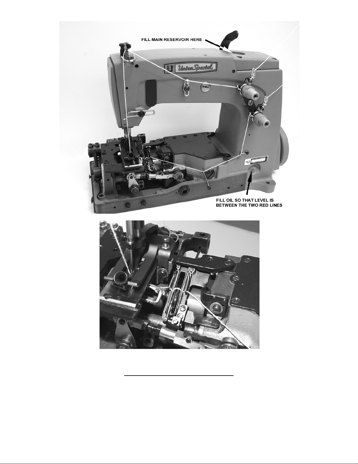
Fig 1
THREADING AND OILING DIAGRAM
For 401 stitch, thread machine as indicated above. The looper threading has been enlarged for clarity.
For 101 stitch, thread machine using needle thread only.
The oil has been drained from the machine before shipping and the reservoir must be filled before starting
to operate. Maintain oil level between the two red lines and add oil when oil level drops below the
bottom red line. The machine is automatically lubricated and no oiling other than keeping the main
reservoir filled is necessary. For further lubricating instructions refer to paragraph on “LUBRICATION”.
4
Page 5
SAFETY RULES
CAUTION
THIS SAFETY SYMBOL INDICATES YOUR PERSONAL SAFETY IS INVOLVED.
TO PREVENT PERSONAL INJURY:
- All power sources to the machine MUST be TURNED OFF before threading, oiling, adjusting or replacing
parts.
- Wear safety glasses.
- All shields and guards MUST be in position before operating machine.
- DO NOT tamper with safety shields, guards, etc., while machine is in operation.
LUBRICATION
Use a straight mineral oil with a Saybolt viscosity of 90 to 125 seconds at 100 degrees F. This is equivalent
to UNION SPECIAL Specification No. 175.
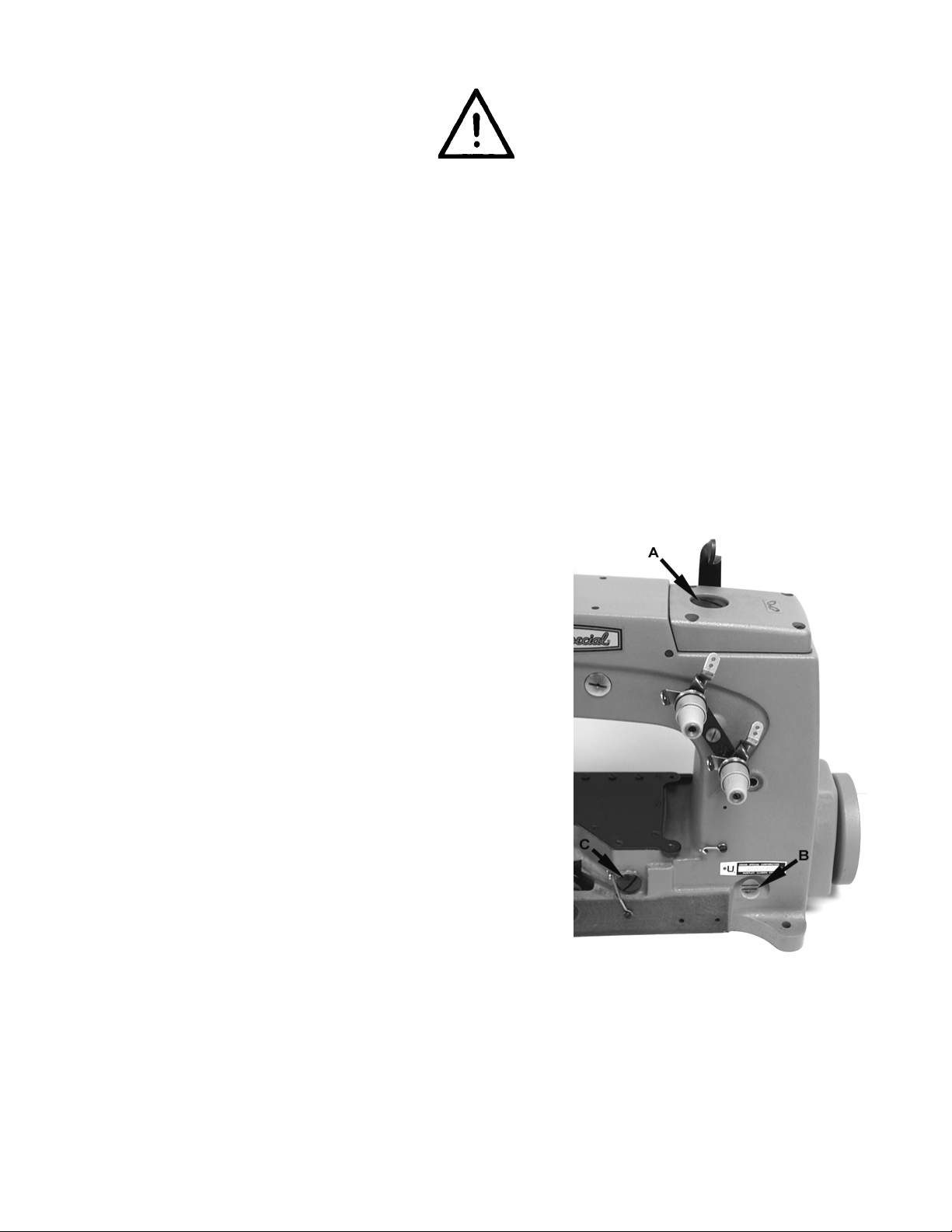
Before operating, fill machine with oil at plug screw (A, Fig. 2).
While filling machine with oil, check gauge (B). When proper
oil level is reached, the oil level should appear in the center
between the two red lines on gauge (B). It is recommended to
always check oil level before operating to be sure machine is
filled between the lines. CAUTION: DO NOT over fill machine.
To drain oil, remove plug screw, at right, in front, below
handwheel or lower crank chamber cover on back of machine. Oil must be changed every 2000 operating hours to
minimize wear.
On new machines, or a machine out of service for an extended period of time; lubricate machine as follows:
Remove head cover, clean out lint, then directly oil needle bar
link and needle bar. Replace head cover and fill machine with
oil to proper level. Run machine at low RPM to ensure proper
lubrication of components preventing any damage which may
occur from lack of oil distribution.
Fig 2
5
Page 6
SYNCHRONIZING LOOPER AND NEEDLE MOTIONS
Synchronization is the most important adjustment
involving the needle and looper motion relation,
because it maintains the needle-looper relation at
both the needle loop taking time, as well as when
the needle enters the looper triangle. This adjustment is best made using synchronization gauge set
TT34.
Remove the throat plate, feed dog, looper and
needle thread take-up wire, (also called strike-off
wire). Fig 3 Using gauge set TT34, re-attach the
throat plate (A) to the throat plate support with the
throat plate screws. Insert the pin (B) into the hole
for the looper and tighten with its screw. Turn the
handwheel in operating direction, (towards the
operator), until the pin lightly touches the right
edge of the throat plate. Insert the indicator (C)
into the hole for the needle thread take-up wire,
and move it up or down until the pointer (D) on the
indicator reads at "0", and then tighten the screw.
Now turn the handwheel in opposite of operating
direction (away from the operator), until the pin
again lightly touches the right edge of the plate. If
the machine is synchronized the pointer on the
indicator should again read "0". If the pointer is
above or below the "0", the machine is out of
synchronization. A variation of one line is allowable.
To synchronize the machine the following procedure should be followed. Thread screw (F) (99271),
from gauge kit TT34, into the looper drive lever
rocker shaft through the center of the thrust adjust-
Fig 3
"0" (Fig. 3A). Loosen screw (E) in the looper drive lever and pull screw (F), (99271), slightly toward the
operator. Retighten screw (E) in the looper drive lever and recheck the synchronization as outlined
above. Repeat as necessary to obtain proper synchronization.
If pointer on the indicator reads below the "0", (Fig. 3B). Loosen screw (E) in the looper drive lever and tap
screw (F), (99271), slightly away from the operator. Retighten screw (E) in the looper drive lever and
recheck the synchronization as outlined above. Repeat as necessary to obtain proper synchronization.
If synchronization gauge set TT34 is not available, the following procedure can be used.
ing screw.
If the pointer (D) on the indicator reads above the
Fig 3A
6
Page 7
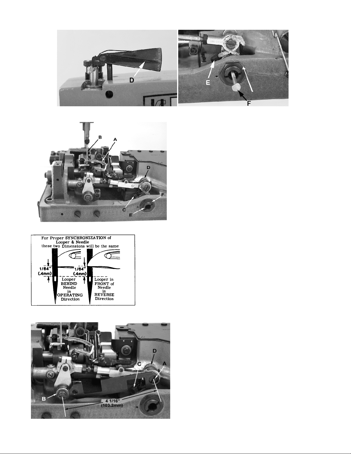
SYNCHRONIZING LOOPER AND NEEDLE MOTIONS (CONTINUED)
Fig 3B
Turn handwheel in the operating direction until the
point of the looper (A, Fig. 4) moving to the left, is
even with the left side of needle (B). Note the height
of the eye of the needle with respect to the looper
point (See Fig. 4A). Turn the handwheel in the reverse direction until the point of the looper again
moving to the left, is even with the left side of needle
(See Fig. 4A). If the height of the eye of the needle
with respect to the looper point are the same,
looper and needle motions are synchronized - a
variation of .005 inch (.127mm) is allowable. If the
distance from the eye of the needle to the point of
the looper is greater when the handwheel is turned
in the operating direction, the looper drive lever
rocker shaft will have to be moved slightly towards
the rear. Moving the shaft towards the front acts the
Fig 4
NOTE: The 1/64 inch (.4mm) dimension shown in Fig. 4A is
reverse.
for final setting of needle bar height.
Fig 4A
Fig 5
Adjust looper drive rocker lever shaft as follows:
Loosen screw (C, Fig. 4) in looper drive lever (D). A rod of .14640 thd. or Union Special Screw No. 99271 can be threaded into
the looper drive lever rocker shaft through the center of thrust
adjusting screw (E). Tap or pull slightly as required to position
shaft for proper synchronization. Tighten screw (C) securely and
remove rod or screw used to position shaft.
Loosen lock nut (F) and TORQUE thrust adjjusting
screw (E) to 6 in. lbs. (7cm/kg); re-tighten lock nut
(F) securely.
With the looper at extreme right end of travel,
check location of the right looper connecting rod
bearing using gauge No. TT35. Place large hole of
gauge over threaded stud (A, Fig. 5). The left end
of gauge should locate against the RIGHT side of
looper rocker cone (B). If adjustment is necessary,
loosen clamp screw (C) and reposition looper drive
lever (D) as required, then tighten screw (C).
If gauge is not available, check setting with a
scale. Distance between the centerline of rocker
cone and centerline of looper drive lever stud
should be 4 1/16 inch (103.2mm) as shown in Fig. 5
when looper is at its extreme right end of travel.
7
Page 8
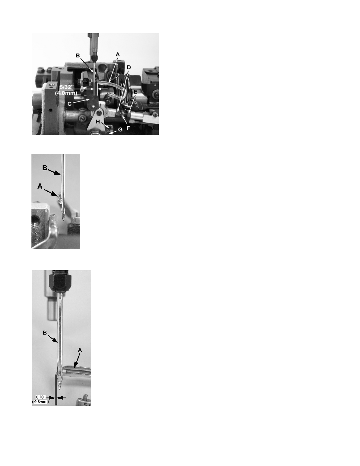
LOOPER AND LOOPER NEEDLE GUARD SETTINGS
Insert a new needle, type and size specified. Looper
gauge is 5/32 inch (4.Omm) which is the distance from
point of looper (A, Fig. 6) to centerline of needle (B)
when looper is at extreme right end of its travel. Looper
gauge No. 21225-5/32 (C) is available for this setting.
Adjustment can be made by loosening nut (D),(it has a
left hand thread) and nut (E); turn connecting rod (F) as
required to attain specified dimension. Hold connecting
rod in position and tighten nut (E), then nut (D). NOTE: Be
sure that the left ball joint is in a vertical position and
does not bind after adjustment.
Fig 6
While turning handwheel in operating direction and the looper (A, Fig. 7) moves to the
left, its point should be set to pass the rear of the needle (B) with .003" to .005" (.08 to
.13mm) clearance. Adjustment can be made by loosening screw (G, Fig. 6), turn stop
screw (H) clockwise to move looper towards the rear, counterclockwise acts the
reverse. It is suggested to hold looper towards the front while making this adjustment.
Tighten screw (G) after adjustment has been made and recheck movement of
looper.
Fig 7
Looper needle guard (attached to looper), 56100Z28B only, should be set with the
looper point set to the centerline of the needle, set front guard 0.005" to 0.010" (0.13
to 0.25 mm) away from looper.
NEEDLE BAR HEIGHT
Turn handwheel to position point of looper (A, Fig. 8) 0.20" (0.5mm) past the left
side of needle (B). At this time the top of the eye of the needle (B) should be
even with the under side of the looper (A). To make adjustment, loosen screw (C
Fig. 15) and move needle bar (A) up or down as required.
SETTING 101 STITCH RETAINER
56100Z30B & 56100Z31B
The 101 stitch retainer is used to hold open the needle loop as the looper moves
to the right so that the needle can enter the loop to form the 101 stitch. To set
the retainer.
Remove the throat plate and set the retainer (A, Fig 9) so that the tip is
approximately 3/32” (2.4mm) from the front of the needle hole in the throat plate
and tighten screw (B). The retainer may need to be move in or out slightly if
skipping or malformed stitches occur while sewing.
Fig 8
Attach the throat plate and looper/spreader to the machine. Turn the
handwheel in operating direction until the looper moving to the right is directly
under the tip of the retainer (Fig. 9A). Adjust the retainer tip up or down with
screw (C, Fig 9B) so that there is .003” to .005” (0.10mm to 0.13mm) clearance
between the top of the looper/spreader and the bottom tip of the retainer and
then tighten screw (C).
8
Page 9
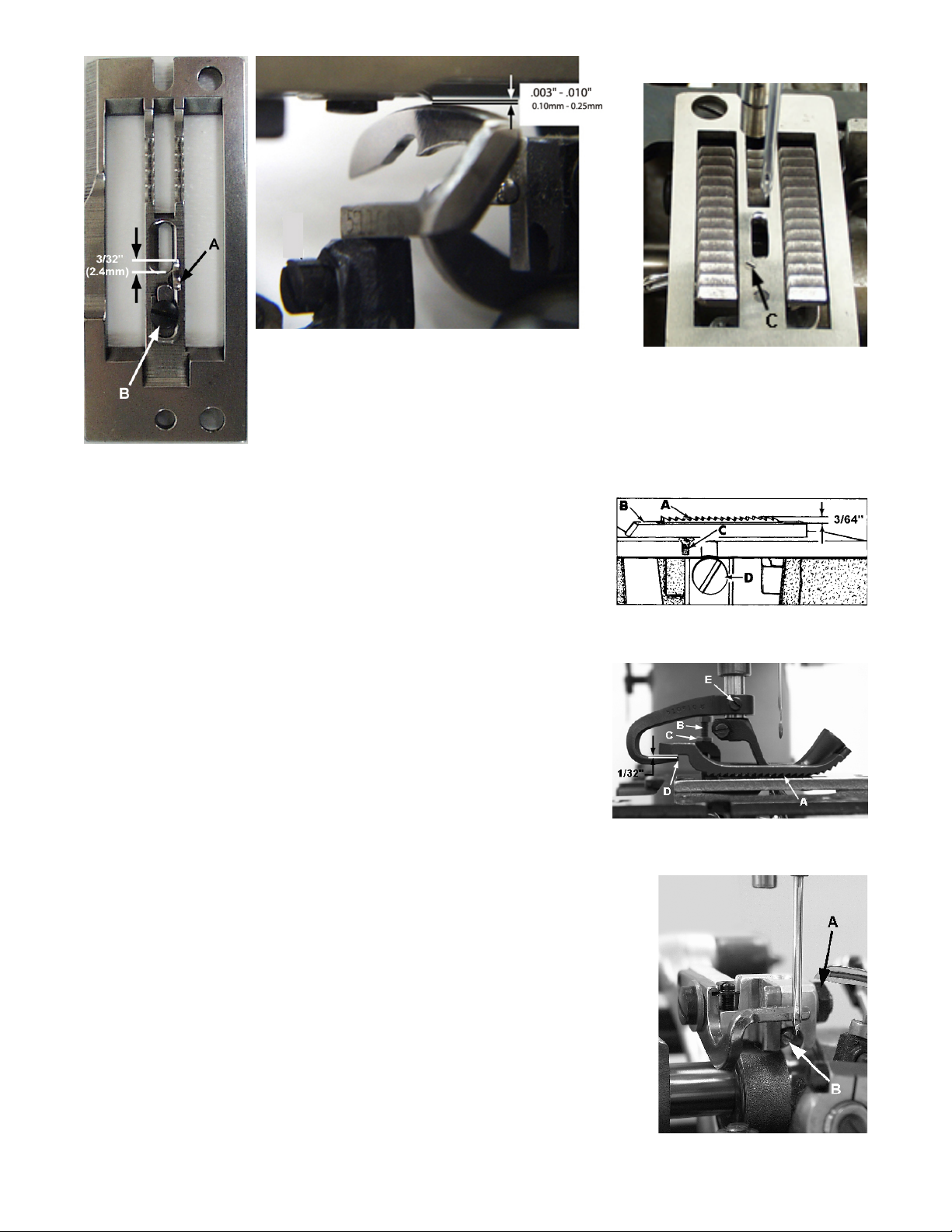
Fig 9A
Fig 9B
Fig 9
Feed dog (A, Fig. 10) should be centered in throat plate (B)with
equal clearance on all sides and ends with feed travel set to
desired stitch length. At highest point of travel, tips of feed dog
teeth should extend the depth of 3/64" above throat plate and
parallel to same. Screw (C) should be set to support feed dog
after screw (D) has been loosened which secures feed dog in
position.
Parallel adjustment can be made by loosening nut (A, Fig. 11) and
turn screw (B) clockwise to lower front of feed dog, counterclockwise acts the reverse. When properly set, retighten nut (A).
Right to left adjustment can be made by loosening screws (G, Fig.
12) and slightly move feed rocker (H) on feed rocker shaft (J) as
required, then retighten screws. Check to ensure that feed rocker
arm (K) does not bind after adjustment.
Forward or rearward centering of feed dog can be accomplished
by loosening nuts (L, Fig. 12), move feed rocker (H) as required and
retighten nut.
FEED DOG SETTINGS
SETTING THE UPPER FEED DOG
Set the up upper feed dog so at it lowest position the teeth will just contact the lower feed dog teeth (A, Fig 10A). To make this adjustment,
loosen nut (C) and turn screw (B) up or down as required. Lock nut (C)
after adjustment has been made.
Note: It may be necessary to raise the upper feed dog for thick materials
or if tearing of the tape occurs.
Fig 10
Fig 10A
SETTING THE UPPER FEED DOG LIFT LEVER
With the upper feed dog at its lowest position, set the lift lever so the there
is approximately 1/32” clearance between the top of the lift lever and the
bottom of the feed dog heel. (D, Fig 10A) To make this adjustment loosen
screw (E) and move the lift lever up or down as required.
9
Fig 11
Page 10
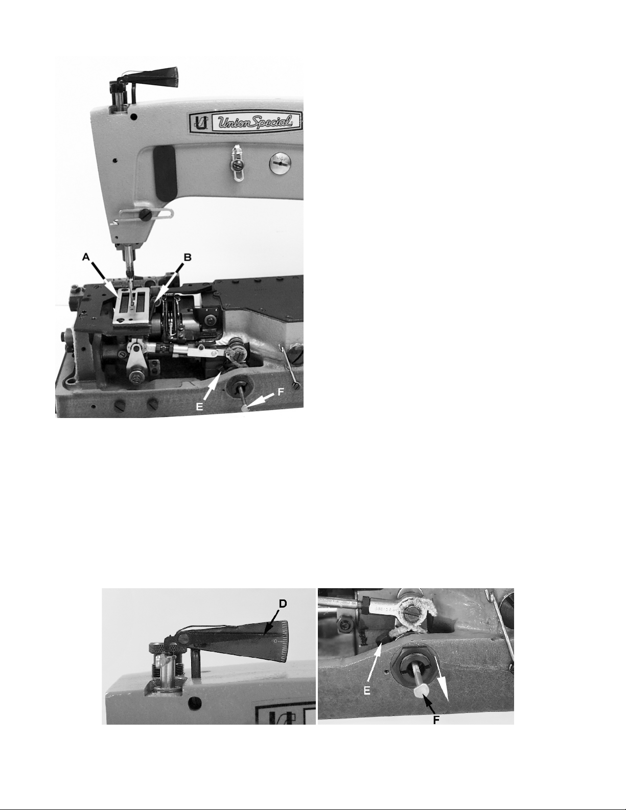
CHANGING STITCH LENGTH
Set the stitch to required length.This is
accomplished by loosening lock nut
(A, Fig.12) 1/2 turn, (it has a left hand
thread) on the end of the stitch
regulating stud and turning stitch
adjusting screw (B) located under the
left end of the cloth plate in the head
of the mainshaft (C), which is marked
with “L” and “S”. Turning the screw in
a clockwise direction shortens the
stitch (moves stitch regulating stud
toward the “S”) and turning it in a
counterclockwise direction lengthens
the stitch (moves stitch regulator stud
toward the “L”). Retighten the lock
nut securely. To prevent destructive
damage to the feed drive bearing,
key screw (D) must engage the “U”
shaped key slot in ferrule (E).
LUBRICATING FEED BAR SHAFT
Fig 12
Grease fittings have been added to
both ends of feed bar shaft (F, Fig 12).
It is advisable to add #2 bearing
grease at these points every month
using grease gun AS60-187. A can of
grease can be ordered under part
number GR18.
REAR NEEDLE GUARD
Rotate handwheel in operating direction to position
looper point to just enter the scarf of needle. At this time
the needle guard (A, Fig 13) should be at its extreme end
of forward travel. Set the guard front to back as close as
possible without touching the needle. Guard should be
set as low as possible, yet have its vertical face approach above the needle point 1/32" +1/64" (0.8mm
+0.4mm). To move the needle guard forward or backward, loosen the screw (B), move needle guard as
required, and retighten screw. To raise or lower needle
guard, loosen screw (B), and turn screw (C) clockwise to
lower needle guard or counterclockwise to raise it.
Retighten screw (B) after guard is properly set.
NOTE: Any change in stitch length will require a
change in rear needle guard setting.
Fig 13
10
Page 11
THREADING
Draw looper and needle threads into the machine and start
operating on a piece of fabric. Refer to threading diagram
(Fig. 1) for manner of threading this machine.
LOOPER THREAD CAST-OFF WIRE
Looper thread cast-off wire (A, Fig. 14) located on the take-up
shield (B) controls the amount of slack thread in the system
and can be moved to any position. It should be set laterally so
that it is midway between the two discs of take-up (C) and the
tip parallel with the discs.
It is usually set toward the take-up to almost the limit of its slot
so that it barely clears the highest point of the take-up. The
height and lateral adjustment of the retainer affects the
control of looper thread as looper moves to the left. Ordinarily it will be set in approximately a horizontal position. More
looper thread is given to the stitch when the retainer is raised
and set towards the take-up. However, if the retainer is raised
too high, the looper thread triangle may be wiped under the
blade of the looper, causing traingle skips or pulled down
stitches. This can be checked by observing the action of the
looper thread as the looper moves to the left.
THREAD TENSIONS
Fig 14
Tension on the needle thread should be only sufficient to produce
uniform stitches on the under surface of the fabric. Tension on the
looper thread should be just sufficient to steady the thread.
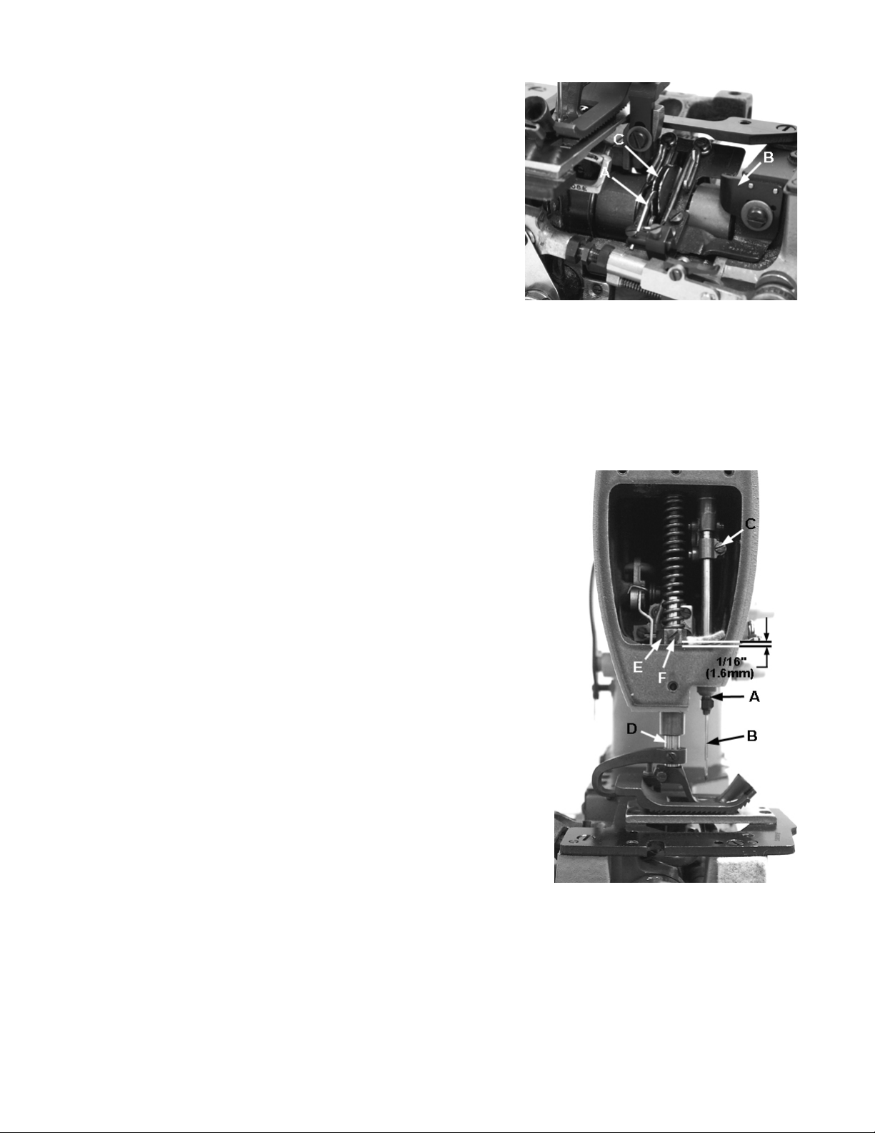
PRESSER BAR HEIGHT
Height of presser bar (D, Fig. 15) is set correctly if it is possible to
remove the presser foot when the foot lifter lever, located at the
back of the machine and extending above the upper crank
chamber cover is fully actuated (pulled to the right). There should
be approximately 1/16 inch (1.6mm) clearance between lower
surface of the presser bar connection and guide (E) and bottom
surface of head opening in the bed when foot lifter lever is released and presser foot lying flat on the throat plate with feed dog
below throat plate.
Adjustment can be made by turning handwheel to position needle
bar at bottom of stroke. Loosen screw (F) and while holding
presser foot down on throat plate, position presser bar connection
and guide as required to attain specified clearance and retighten
screw.
PRESSER FOOT PRESSURE
Regulate the presser spring regulating screw (A, Fig. 16) so that it
exerts only enough pressure on the presser foot to feed the work
uniformly when a slight tension is placed on the fabric. Turning it
clockwise increases the pressure, counterclockwise acts the
reverse.
Fig 15
11
Page 12

SETTING NEEDLE THREAD GUIDE AND FRAME EYELET
For 56100Z28B Turn handwheel in operating direction until the needle bar
reaches its lowest position. Set needle thread take-up wire (B, Fig. 16 so
that its thread contact surface is even with the center of the needle bar
thread eyelet (C). Lower this setting for a smaller needle thread loop, raise
for a larger loop. Set needle thread frame eyelet (D) so that it is approximately 3/4 inch (19.1mm) above centerline of its attaching screw (Fig. 16).
For 56100Z30B & Z31B Set the needle thread take-up wire (E, Fig 16A) to
the lowest position. Set needle thread frame eyelet, (F) so that the screw
is centered in the eyelet slot. Set the needle thread frame eyelet, lower,
(G) so that the screw is just left of the center of the eyelet slot.
Fig 16
Fig 16A
TORQUE REQUIREMENTS
Torque specifications given in this catalog are measured in inch-pounds or
centimeter/kilograms. All straps and eccentrics must be tightened to 1921 in. lbs. (22-24cm/kg) unless otherwise noted.
All nuts, bolts, screws, etc., without torque specifications must be secured
as tightly as possible, unless otherwise noted. Special torque specifications
of connecting rods, links, screws, etc., are shown on part illustrations.
SPECIAL INSTRUCTIONS
NEEDLE LEVER
When adjusting needle lever or replacing related parts, follow
instructions in sequence as listed:
1. Install “O” rings (A, Fig. 17) onto needle lever stud (B) and
thrust collar (C).
2. With needle lever (D) in machine and positioned properly;
insert stud (B) through hole in needle lever until its shoulder
contacts the needle lever and the word “UP” on stud is in
the upright position. While making sure no binding exists in
the needle bar link, secure stud (B) with the front set screw
in top of machine bed.
3. Install temper load ring (E) and compression cups (F) onto
stud (B), then push ring and cups through opening in
Fig 17
4. Install thrust collar (C) onto stud (B) being careful not to damage “O” ring. Compress components together
by tighening screw (G) until washer (H) bottoms against stud (B). Secure stud (B) in position using the rear set
screw in top of bed.
5. To check temper load ring for proper compression, remove
6. With indented “UP” on stud (B) in upright position, install
Fig 18
machine bed.
screw (G) from stud (B) and loosen rear set screw in top of
bed. Thrust collar (C) should spring out .003 - .007 inch (.08
.18mm). Compress load ring in reverse order, then tighten
rear set screw.
bearing oiler (J) so its hook sets in oil supply hole (K) of stud.
When hook and stud are secured in their proper positions,
the proper amount of oil will be channeled to stud for
lubricating needle lever (D).
12
Page 13

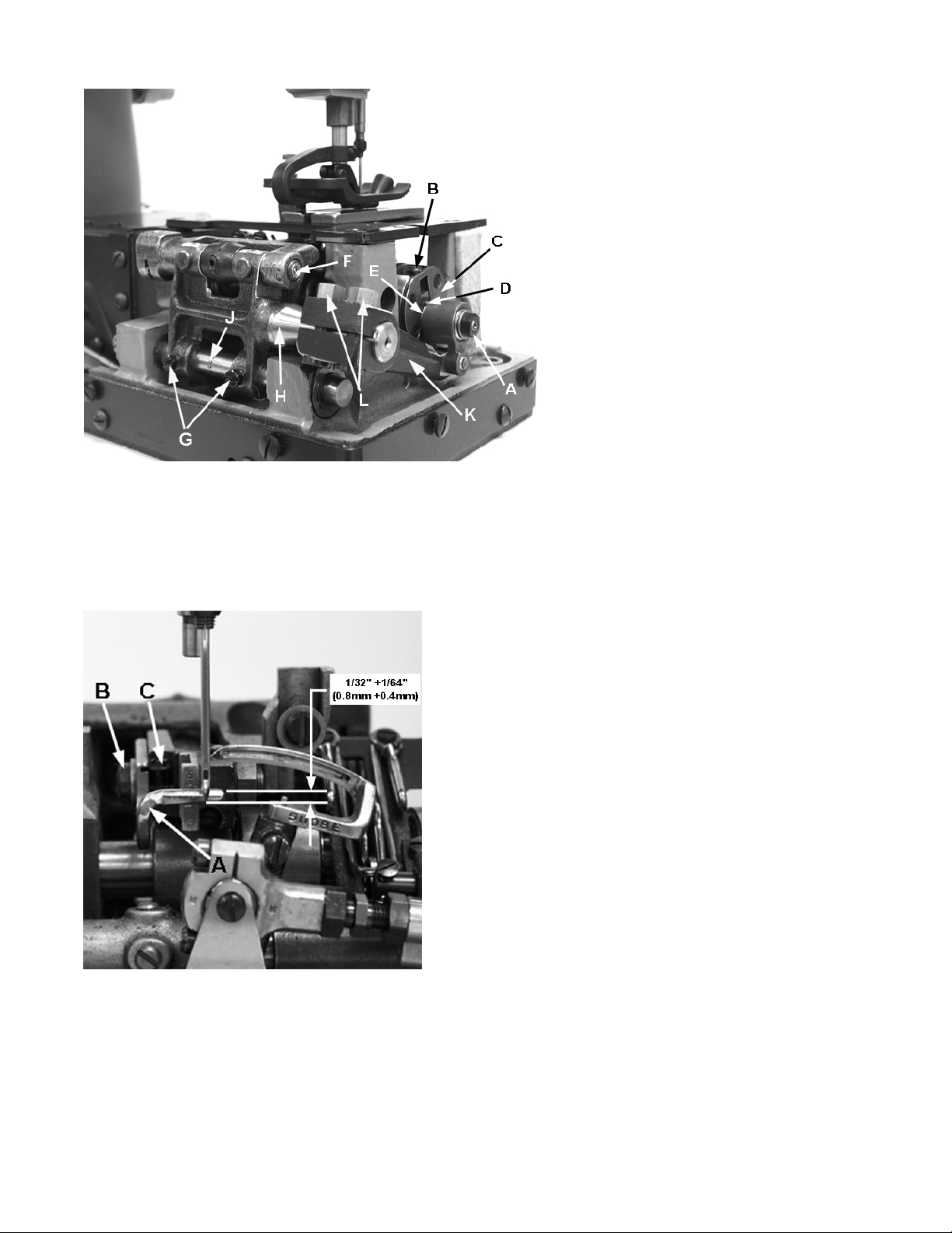
ALIGNING MAINSHAFT TO CRANKSHAFT
As viewed looking down from rear of machine, spot
screws (A. Fig. 18) in the couplings must align with
the spots in the looper drive crank (B) and set screws
(C) must align with the flats on crankshaft (D) and
mainshaft (E).
Mainshaft must be positioned laterally with .045 inch
(1.14mm) clearance between the right side of its
head and the bed .060" (1.5mm) casting as shown in
Fig. 19.
Looper drive crank (B, Fig. 18) must be positioned
laterally with 1/32 inch (.8mm) clearance between it
and mainshaft (E) as shown in Fig. 18. Once these
settings are made, it is very important that the
coplings are tightened in the following sequence for
best performance.
Tighten spot screws (A) temporarily, to the looper
drive crank. Tighten set screws (C) temporarily, to the
crankshaft and mainshaft. Torque screws (F) to 19 - 21
in. lbs. (22 - 24 cm/kg). Loosen spot screws (A) and
set screws (C). Re-torque screws (F) to 19 - 21 in. lbs.
(22 - 24 cm/kg), then torque screws (A and C) to 19 21 in. lbs. (22 - 24cm/kg).
Fig 19
The oil drip plate (A, Fig. 20) located in the oil reservoir
should be positioned with its tip in the recessed cut
out in the bed casting, as far to the left as possible
without touching. It has elongated mounting holes
and can be adjusted by loosening (2) screws (B) in top
of the oil reservoir back cover to position as required,
retighten screws.
Fig 20
13
Page 14

Before this machine left the factory it was adjusted and inspected to give you the utmost satisfaction and
durability at all times. If, however, the machine has been readjusted and is not sewing properly, see the chart
below for suggestions which may prove beneficial to you.
SKIPPED STITCHES
noitidnoCsesuaCseruC
llamsootpooleldeeNediugdaerhteldeenemarF
daerhteldeenemarfesiaR
woloottes
tonpool,ekortsfomottob
g
tadehctertsdaerhteldeeN
.ylthgilsediu
teleyedaerhtemarfrewoL
ldeenecuderro/dna
noisnete
deveilerhctertsllitdemrof
desaercdaerhteldeeN
dnathgitootsitiesuaceb
tohsieldeen
ybdehcnipdaerhteldeeN
porD
eldeenemarfrewol
noisnetecuder
,eldeeneyellabezisrevoesU
,teleye
ylthgilsdraugeldeen
gnispalloc,draugeldeen
pooleldeen
dnuoragnitsiwtdaerhT
eldeen
llamssapooleldeenpeeK
eldeenpeek,elbissopsa
.muminimaotnoisnetdaerht
ttsiwttfelaesU
daerh
nignikcitsdaerhteldeeN
daerhtnotnacirbulesU
taehoteud,sevoorgeldeen
N
hguoneesirtonseodeldee
ylreporppooleldeenmrofot
hcni23/1ot
46/1eguagrepoolesaercnI
pooleldeensessimrepooL
psa
maesa
ffognimocsitoofresser
eN
ninwoddlehtonsilairetaM
gniggalfsidnamaesfotnorf
sdrawotgnitcelfedelde
gnikcitssirabresserpfieeS
eldeentniopprahsesU
rotarepo
ylreporpdemrofpooleldeeN
hgihoottesrabeldeeNylthgilsrabeldeenrewoL
yb.yawehtfotuodehsurbtub
repool
pooleldeensessimrepooL
otgniyrtsirotareponehw
sdnerosmaeshctam
eeN
drawotgnitcelfedeld
gnidlohebyamohwrotarepo
elihwlairetamnokcab
fosdnerosmaesgnihctam
tnemrag
ssimeldeeN
noelgnairtse
edisdaerhtrepool
ton,esoolootdaerhtrepooL
elgnairtdoogagnikam
detcelfedgniebeldeeN
ehtot
noisnet
daerhtrepoolesaercnI
tniopeldeennorrubybraer
nognilluprotarepooteudro
gnicnalgeldeenro,lairetam
imocnehwffo
maesanogn
es
ylevissecxekcabdlohtonoD
daylreporP.lairetamno
tsuj
reporpaniatniamdnadeef
ostoofnoerusserpgnideef
kcabdlohtonseodrotarepo
ehttalairetamlluptonoD
oteldeenprahsaesU.kcab
ffognicnalgmorfeldeenpots
rrubrofeldeenkcehC.ma
NOTE: More detailed information concerning the double locked stitch (stitch type 401) is available
under “Stitch Formation, Type 401”.
14
Page 15

ORDERING REPAIR PARTS
ILLUSTRATIONS
This catalog has been arranged to simplify ordering repair parts. Exploded views of various sections of
the mechanism are shown so that the parts may be seen in their actual position in the machine. On the
page opposite the illustration will be found a listing of the parts with their part numbers, descriptions and
the number of pieces required in the particular view being shown.
Numbers in the first column are reference numbers only, and merely indicate the position of that part in
the illustration. Reference numbers should never be used in ordering parts. Always use the part number
listed in the second column.
Component parts of sub-assemblies which can be furnished for repairs are indicated by indenting their
descriptions under the description of the main sub-assembly. Example:
48 2910 5AK Crank Assembly, looper driving lever ........................................................... 1
49 22587K Screw, bearing cap ,(upper) ............................................................ 2
50 56343C Guide, ball joint ................................................................................
1
51 56343E Splasher, oil ....................................................................................... 1
52 22559A Screw, bearingcap (lower) ............................................................... 2
It will be noted in the above example that the eccentric, ball stud, and bearing are not listed. The reason
is that replacement of these parts individually is not recommended, so the complete sub-assembly should
be ordered.
At the back of the book will be found a numerical index of all the parts shown in this book. This will facilitate locating the illustration and description when only the part number is known.
IDENTIFYING PARTS
Where the construction permits, each part is stamped with its part number. On some of the smaller parts,
and on those where construction does not permit, an identification letter is stamped in to distinguish the
part from simil’ar ones.
Part numbers represent the same part, regardless of catalog in which they appear.
IMPORTANT! ON ALL ORDERS, PLEASE INCLUDE PART NAME AND STYLE OF MACHINE FOR WHICH PART IS
ORDERED.
USE GENUINE REPAIR PARTS
Success in the operation of these machines can be secured only with genuine UNION SPECIAL repair
parts as furnished by the Union Special Corporation, its subsidiaries and authorized distributors. They are
designed according to the most approved scientific principles, and are made with utmost precision.
Maximum efficiency and durability are assured.
15
Page 16

16
Page 17

MAIN FRAME, CAST-OFF PLATE, MISCELLANEOUS COVERS
Ref.
No.
Part No.
1.
22829
2.
21375CE
3.
98A
4.
52A
5.
22593
6.
51158D
7.
51104L
8.
50-216BLK
9.
51157J
10.
21657E
11.
22528
12.
J87J
13.
77
14.
51204C
15.
51104J
-
K74642
16.
51204A
17.
22798A
18.
51204
19.
52958B
20.
22569C
21.
56382
22.
56382A
23.
56382AT
24.
22585
25.
56393D
26.
7947
27.
56393C
28.
35731A
29.
51294R
30.
660-342
31.
22513
32.
539
33.
20
34.
22548
35.
660-694
36.
22889A
37.
40003956
-
539
38.
20
39.
22848
40.
22894E
41.
56382AX
42.
22548
43.
29480BFD
44.
56193D
45.
56382DB
46.
56193N
47.
11638M
48.
56382AZ
49.
TA0750404RO
50.
56382AW
51.
56382G
52.
22524
53.
22585A
54.
22839
55.
51124E
51124M
56.
22570
57.
51180H
58.
51280J
59.
22570A
60.
56382J
61.
56382AV
62.
22848
63.
56382AA
64.
56382AU
65.
56382Y
66.
56382AB
67.
22524
Description
Screw ......................................................................................................................
Guard, belt .............................................................................................................
Screw ......................................................................................................................
Eyelet, frame looper thread .................................................................................
Screw ......................................................................................................................
Eyelet, take-up .......................................................................................................
Wire, cast-off .........................................................................................................
Pin, dowel ...............................................................................................................
Support, cast-off wire ...........................................................................................
Washer ...................................................................................................................
Screw ......................................................................................................................
Screw ......................................................................................................................
Screw, for 56100Z28B......................................................................................
Support, auxiliary cast-off, for 56100Z28B.....................................................
Cast-off, auxiliary .............................................................................................
Cast-off, auxiliary, for 56100Z30B, Z31B ...............................................................
Support, cast-off wire, for 56100Z28B.............................................................
Screw, for 56100Z28B.......................................................................................
Wire, cast-off, for 56100Z28B..........................................................................
Eyelet, frame looper thread .................................................................................
Screw ......................................................................................................................
Cover, head ..........................................................................................................
Felt ....................................................................................................................
Gasket ....................................................................................................................
Screw ......................................................................................................................
Clamp, head oil tube .............................................................................................
Nut ..........................................................................................................................
Block, head oil tube mounying .............................................................................
Plate, presser bar connection guide ..................................................................
Screw ......................................................................................................................
Lockwasher ...........................................................................................................
Screw ......................................................................................................................
Eyelet, frame needle thread ................................................................................
Washer ...................................................................................................................
Screw ......................................................................................................................
Gasket, needle lever eyelet .................................................................................
Screw, adapter .....................................................................................................
Eyelet, frame needle thread, for 56100Z30B, Z31B ............................................
Eyelet, frame needle thread, for 56100Z28B ......................................................
Washer ...................................................................................................................
Screw ......................................................................................................................
Screw, needle lever thrust collar and stud ..........................................................
Gasket ....................................................................................................................
Screw.................................. ..............................................................................
Oil Return Pump Kit...........................................................................................
Pump Assembly.........................................................................................
Cover, lower crank chanmber.................................................................
Oil return tube assembly.............................................................................
Nut................................................................................................................
Felt................................................................................................................
Plug...............................................................................................................
Gasket...............................................................................................................
Cover, top oil reservoir ..........................................................................................
Screw ......................................................................................................................
Screw ......................................................................................................................
Screw, throat plate support ..................................................................................
Throat Plate, for style 56100Z28B ..........................................................................
Throat Plate, for style 56100Z30B, Z31B ................................................................
Screw ......................................................................................................................
Support, throat plate ............................................................................................
Pin, dowel .........................................................................................................
Screw ......................................................................................................................
Cover, looper drive shaft .....................................................................................
Gasket ....................................................................................................................
Screw ......................................................................................................................
Cover, back, oil reservoir .....................................................................................
Gasket ....................................................................................................................
Block, clamping .....................................................................................................
Plate, oil drip ...........................................................................................................
Screw ......................................................................................................................
Amt.
Req.
2
1
2
1
2
2
1
2
1
1
1
2
1
1
1
1
1
1
1
1
2
1
1
1
1
1
1
1
2
1
1
3
1
1
1
1
1
1
1
1
1
2
1
4
1
1
1
1
1
1
1
1
1
8
3
3
1
1
2
1
2
2
1
1
9
1
1
1
1
2
17
Page 18

18
Page 19

MAIN FRAME, BUSHINGS, OIL GAUGE AND MISCELLANEOUS OILING PARTS
Ref.
No.
1.
2.
3.
4.
5.
6.
7.
8.
9.
10.
11.
12.
13.
14.
15.
16.
16A.
17.
18.
19.
20.
21.
22.
23.
24.
25.
26.
27.
28.
29.
30.
31.
32.
33.
34.
35.
36.
37.
38.
39.
40.
41.
42.
43.
44.
45.
46.
47.
48.
49.
50.
51.
52.
Part No.
22539R
51-902BLK
56390E
57890B
22569B
56390H
660-665
56390J
56382AC
90
56382AY
K74592
22541C
22733E
56382M
K74335
B51101A
22839C
24X
25
K74334
51281AC
35772H
22760A
22845B
80
G51382BA
22848
99295
56170
-
K74922
51154E
95
56393W
GR-56393T
56393L
56154
51257AA
57836B
56344G
666-259
50-895BLK
56193A
52942W
56190
57842B
35897BV
56390G
21657X
G51381BA
G51381BD
52978Z
51282AJ
25S
-
21227HR
Description
Screw, plug ............................................................................................................
Gauge, oil sight ......................................................................................................
Gasket ....................................................................................................................
Housing, crankshaft bushing, includes bushing ...................................................
Screw ......................................................................................................................
Washer, thrust ........................................................................................................
Bearing, needle, thrust .........................................................................................
Ring, pilot ................................................................................................................
Plate, oil and baffle ................................................................................................
Screw ......................................................................................................................
Gasket ....................................................................................................................
Cover, upper crank chamber ..............................................................................
Screw ......................................................................................................................
Plug, oil filter ...........................................................................................................
Gasket ....................................................................................................................
Cloth Plate, for styles 56100Z28B, Z30B ...............................................................
Cloth Plate, for styles 56100Z31B .........................................................................
Screw ......................................................................................................................
Guide, edge(Extra send and charge) ............................................................
Screw, for 24X (Extra send and charge)........................................................
Cover, cloth plate, for styles 56100Z28B, Z30B ....................................................
Spring ...............................................................................................................
Washer, spring ................................................................................................
Screw ...............................................................................................................
Screw ...............................................................................................................
Screw ......................................................................................................................
Bracket, for shields ................................................................................................
Screw ......................................................................................................................
Screw ......................................................................................................................
Wire, needle thread take-up, for styles 56100Z28B ............................................
Wire, needle thread take-up, for styles 56100Z30B, Z31B ...................................
Bushing, needle bar (upper) .................................................................................
Screw ......................................................................................................................
Pad, felt ..................................................................................................................
Pump Assembly, oil, head ......................................................................................
Felt ....................................................................................................................
Bushing, needle bar (lower) ..................................................................................
Bushing, presser bar (lower) .................................................................................
Bushing, feed rocker shaft ....................................................................................
Bearing Assembly .................................................................................................
Felt ..........................................................................................................................
Bushing, looper rocker shaft .................................................................................
Felt, machine base (front) ....................................................................................
Bushing, looper drive lever shaft (front) ...............................................................
Bushing, mainshaft (intermediate) .......................................................................
Bushing, looper drive lever shaft (rear) ................................................................
Filter, oil intake .......................................................................................................
Bushing, mainshaft (inner right) .............................................................................
Bushing, tension release lever shaft .....................................................................
Oil Shield, left .........................................................................................................
Oil Shield, rear ........................................................................................................
Shim stop ................................................................................................................
Hinged oil shield ......................................................................................................
Screw ......................................................................................................................
Aligning Tool, for replacing 56344G bearing assembly (not shown) .................
Amt.
Req.
1
1
1
1
3
4
2
2
1
2
1
1
4
2
1
1
1
2
1
2
1
1
3
3
1
2/3
1
3
3
1
1
1
1
1
1
1
1
1
2
1
1
2
1
1
1
1
1
1
1
1
1
1
1
2
1
19
Page 20

20
Page 21

CRANKSHAFT, NEEDLE LEVER AND LOOPER DRIVING PARTS
Ref.
No.
1.
2.
3.
4.
4A.
5.
5A.
6.
7.
8.
8A
9.
10.
11.
12.
13.
14.
15.
16.
17.
18.
19.
20.
21.
22.
23.
24.
25.
26.
27.
28.
29.
30.
31.
32.
33.
34.
35.
36.
37.
38.
39.
-
-
40.
41.
42.
43.
44.
45.
46.
47.
48.
-
49.
50.
51.
52.
53.
54.
55.
56.
57.
58.
59.
60.
61.
Part No.
56
51217C
27-435BLK
K74914
K74921
J87J
22585
22586R
GR51250V
51250D
56382AK
660-625
56350E
56350F
660-614
29348AF
77
56354D
51254K
22562A
22564
52336A
WO3
660-215
56350D
29066R
22559G
51216N
51216P
56316
22574
61321L
57821
56321R
22894AB
660-202
57847
95
51247
22894J
29476PB
51216M625
51216M626
51216M627
56316C
12934A
22894C
22894D
56343F
22653L8
29105AK
29105AM
22587K
56343C
56343E
22559A
52942AA
660-202
56390H
660-665
56390J
56342K
CL21
52942AC
56342D
Description
Nut .........................................................................................................................
Needle Bar .............................................................................................................
Washer, needle bar eyelet ..................................................................................
Eyelet, needle bar thread, for style 56100Z28B ..................................................
Eyelet, needle bar thread, for style 56100Z30B, Z31B ........................................
Screw, for K74914 ..................................................................................................
Screw, for K74921 ..................................................................................................
Screw .....................................................................................................................
Gasket ...................................................................................................................
Washer .................................................................................................................
Gasket...............................................................................................................
"O" Ring ..................................................................................................................
Colar, needle lever thrust ....................................................................................
Cup, compression ................................................................................................
Ring, temper load ..................................................................................................
Lever Assembly, needle .......................................................................................
Screw ..............................................................................................................
Link, connecting ............................................................................................
Connection, needle bar ...............................................................................
Screw .......................................................................................................
Screw ..............................................................................................................
Pin, link .............................................................................................................
Yarn ..........................................................................................................
Ring, retaining .................................................................................................
Stud, needle lever ..........................................................................................
Ball Joint, needle lever (upper) .............................................................................
Screw ..............................................................................................................
Washer ..................................................................................................................
Nut .........................................................................................................................
Connecting Rod, needle lever ............................................................................
Screw, for 56100Z28B, Z30B .................................................................................
Plate, retaining, for 56100Z28B, Z30B ..................................................................
Handwheel, for 56100Z28B, Z30B ........................................................................
Pulley ......................................................................................................................
Screw ..............................................................................................................
"O" Ring ..................................................................................................................
Collar, thrust ..........................................................................................................
Screw ..............................................................................................................
Counterweight .....................................................................................................
Screw ..............................................................................................................
Crankshaft Sub-Assembly ....................................................................................
Bearing, needle, .0625 inch (1.588mm) diameter .......................................
Bearing, needle, .0626 inch (1.590mm) diameter .......................................
Bearing, needle, .0627 inch (1.593mm) diameter .......................................
Guide, connecting rod .........................................................................................
Nut .........................................................................................................................
Pump, oil, head (See Ref. No. 32 Page 19) ...........................................................
Pump, oil, base (See Ref. No. 56 Page 17) ............................................................
Screw, set ..............................................................................................................
Screw, spot ............................................................................................................
Coupling ................................................................................................................
Screw ..............................................................................................................
Crank Assembly, looper driving lever, for 56100Z28B .......................................
Crank Assembly, looper driving lever, for 56100Z30B, Z31B ..............................
Screw, bearing cap (upper) .........................................................................
Guide, ball joint ...............................................................................................
Splasher, oil ....................................................................................................
Screw, bearing cap (lower) ..........................................................................
Shaft, looper drive rocker ....................................................................................
"O" Ring ..................................................................................................................
Washer, thrust .......................................................................................................
Bearing, needle thrust ..........................................................................................
Ring, pilot ................................................................................................................
Lever, looper drive, marked "D" ..........................................................................
Wick, oil ..................................................................................................................
Screw, thrust synchronizing adjusting ..................................................................
Nut .........................................................................................................................
21
Amt.
Req.
1
1
1
1
1
1
1
1
1
1
1
2
1
2
1
1
1
1
1
1
1
2
2
4
1
1
2
1
1
2
3
1
1
1
2
1
1
2
1
2
1
28
28
28
1
1
1
1
2
2
2
2
1
1
2
1
1
2
1
1
4
2
2
1
1
1
1
Page 22

22
Page 23

LOOPER ROCKER AND CONNECTING ROD PARTS
Ref.
No.
10.
11.
12.
13.
14.
15.
16.
17.
18.
19.
20.
21.
22.
23.
24.
25.
26.
27.
28.
29.
30.
31.
32.
33.
34.
35.
36.
37.
38.
38A.
39.
40.
41.
42.
43.
44.
45.
46.
47.
48.
49.
1.
-
2.
3.
4.
5.
6.
7.
8.
9.
-
Part No.
K74938
K74292
22764C
51236J
54244L
77
51244B
22519H
WO3
K74290
CO67E
K74295
22894W
56344C
719
98
51246
51244L
96
51110D
73A
51108DA
51108E
51108KA
21210
73
18
29192V
51745
56313
15465F
22894W
258A
22829
56393J
87U
57841
22729C
269
51240D
35741A
18
56341N
20
627
56342K
22882C
20
29476LV
56341F
33795D
22585A
Amt.
Description
Looper avoid eccentric assembly, for 56100Z30B, Z31B ..................................
Looper avoid eccentric assembly, for 56100Z28B ............................................
Screw ..............................................................................................................
Pin, link ....................................................................................................................
Washer, thrust .......................................................................................................
Screw .....................................................................................................................
Arm, looper rocker shaft .......................................................................................
Screw ..............................................................................................................
Yarn .................................................................................................... as required
Shaft, looper rocker .............................................................................................
Cork ........................................................................................................................
Collar, spacing .....................................................................................................
Screw .....................................................................................................................
Frame, looper rocker ...........................................................................................
Screw, stop .....................................................................................................
Screw, set .......................................................................................................
Nut .........................................................................................................................
Washer, thrust .......................................................................................................
Screw, spot ............................................................................................................
Guard, looper needle ..........................................................................................
Screw .....................................................................................................................
Looper, for styles 56100Z28B ...............................................................................
Looper, for styles 56100Z30B, Z31B .....................................................................
Spreader, for styles 56100Z30B, Z31B .................................................................
Collar, Looper, (Extra send and charge)...........................................................
Screw, looper ........................................................................................................
Nut .........................................................................................................................
Rocker Assembly, looper ....................................................................................
Stud, rocker cone ..........................................................................................
Rocker, looper, marked "S" ...........................................................................
Cone, looper rocker ......................................................................................
Screw .......................................................................................................
Nut, check .......................................................................................................
Screw ..............................................................................................................
Oiler, looper connecting rod ball joint (left) ........................................................
Screw .....................................................................................................................
Ball Joint, looper connecting rod (left) ................................................................
Screw ..............................................................................................................
Nut, left hand thread ............................................................................................
Connecting Rod, looper, for styles 56100Z30B, Z31B .........................................
Connecting Rod, looper, for styles 56100Z28B ...................................................
Nut, right hand thread ...........................................................................................
Looper connecting rod jointed section assembly, right, for styles 56100Z30B, Z31B
Washer ..................................................................................................................
Looper lever stud ..................................................................................................
Looper drive lever ................................................................................................
Screw ..............................................................................................................
Washer ...........................................................................................................
Bearing Assembly, looper connecting rod (right), for styles 56100Z28B .......
Ferrule .............................................................................................................
Needle bar guard......................................................................................
Screw.......................................................................................................... 1
Req.
1
1
1
1
1
1
1
1
1
1
1
1
1
1
1
1
1
1
1
1
1
1
1
1
1
1
1
1
1
1
1
2
1
1
1
1
1
2
1
1
1
1
1
1
1
1
1
1
1
1
23
Page 24

CE27
CE27
CE27
CE27
CE27
Union Special
CE27
Loctite
Union Special
CE27
58
57
56
CE27
24
Page 25

MAINSHAFT AND FEED DRIVING PARTS
Ref.
No.
1.
2.
3.
4.
5.
6.
7.
8.
9.
10.
11.
12.
13.
14.
15.
16.
17.
18.
19.
20.
21.
22.
23.
24.
25.
26.
27.
28.
29.
30.
31.
32.
33.
34.
35.
36.
37.
38.
39.
40.
41.
42.
43.
44.
45.
46.
47.
48.
49.
50.
51.
52.
53.
54.
55.
56.
57.
58.
Part No.
K74899
K74879
55235E
6042A
55235D
56336N
56336C
77
51236J
WO3
K74880
22852G
K74877
51134N
51134V
666-170
HA95
51134L
51134M
90
K74297
22764C
22834
51134X
22894C
538
258
6042A
22863
56334E
660-438
41391
56335D
98
56335L
56125
22801
51225W
K74881
51105N
-
C51105N
20
93
K74872
22891B
56322B
51-173BLK
56336D
660-269B
22543C
56336
22798C
K74591
22525A
21657E
269
51123H
22764C
22580D
Description
Feed Mechanism Assembly .................................................................................
Feed Rocker Arm Assembly ..........................................................................
Nut ...........................................................................................................
Washer ....................................................................................................
Stud, locking ............................................................................................
Link, feed crank ..............................................................................................
Ferrule ......................................................................................................
Screw ..............................................................................................................
Pin, link .............................................................................................................
Yarn ..........................................................................................................
Feed Rocker ...................................................................................................
Screw ..............................................................................................................
Feed Bar Shaft ................................................................................................
Feed Bar Spring ..............................................................................................
Pin ...................................................................................................................
Wick .................................................................................................................
Screw ..............................................................................................................
Feed Bar, Upper .............................................................................................
Feed Bar Arm ..................................................................................................
Screw ..............................................................................................................
Feed Lift Eccentric ........................................................................................
Screw .......................................................................................................
Screw, Needle Guard Height Adjusting .......................................................
Feed Bar, Lower .............................................................................................
Screw .......................................................................................................
Screw, Height Adjusting .........................................................................
Nut ...........................................................................................................
Washer ....................................................................................................
Screw, Holder Adjusting .........................................................................
Feed Dog Holder .....................................................................................
Ring, Retaining ......................................................................................................
Washer ..................................................................................................................
Collar, Feed Rocker Shaft ....................................................................................
Screw ..............................................................................................................
Shaft, Feed Rocker ...............................................................................................
Guard, Rear Needle .............................................................................................
Screw ..............................................................................................................
Washer ..................................................................................................................
Screw ....................................................................................................................
Feed Dog
Plated Feed Dog (Extra Send & Charge Item)....................................................
Washer ..................................................................................................................
Screw, Feed Dog ..................................................................................................
Mainshaft ..............................................................................................................
Screw ..............................................................................................................
Gasket ............................................................................................................
Plug, Oil ...........................................................................................................
Insert, Feed Crank Stud ........................................................................................
Ring, Quad .............................................................................................................
Screw, Stitch Regulating ......................................................................................
Stud, Feed Crank, Marked "A" ..............................................................................
Screw ....................................................................................................................
Plate, Mainshaft Head .........................................................................................
Screw ....................................................................................................................
Washer, .................................................................................................................
Nut .........................................................................................................................
Cam, Take-up ........................................................................................................
Screw ....................................................................................................................
Screw ....................................................................................................................
Amt.
Req.
1
1
1
1
1
1
1
3
3
1
1
2
1
1
1
1
1
1
1
1
2
1
1
1
1
1
1
1
1
1
1
1
1
2
1
1
1
1
1
1
1
1
1
1
1
1
1
1
1
1
1
1
1
4
1
1
1
1
1
25
Page 26

26
Page 27

PRESSER FOOT, LIFTER LEVER AND THREAD TENSION PARTS
Ref.
No.
1.
2.
3.
4.
5.
6.
7.
8.
9.
10.
11.
12.
13.
14.
15.
16.
17.
18.
19.
20.
21.
22.
23.
24.
25.
26.
27.
28.
29.
30.
31.
32.
Part No.
51257K
22596F
51257M
402
56383A
53787
56356
22758C
22557G
56383D
56383AA
56383AB
51183B
22758C
51183C
50-703BLK
660-207
53783N
22537
43266
K74923
51491C
80557
52892
22872
51192G
51192B
56392E
109
56392F
51292F14
51292F2
39592AK
39592Z
Description
Bar, presser ............................................................................................................
Screw .....................................................................................................................
Connection and Guide, presser bar ...................................................................
Screw .....................................................................................................................
Link, lifter lever .......................................................................................................
Spring, presser .......................................................................................................
Regulator, presser spring .....................................................................................
Screw .....................................................................................................................
Screw .....................................................................................................................
Spring .....................................................................................................................
Bell Crank, presser foot lifter lever ........................................................................
Connecting Rod, presser foot lifter lever ...........................................................
Lever, presser foot lifter .......................................................................................
Screw .....................................................................................................................
Latch, lever ...........................................................................................................
Pin, stop ..................................................................................................................
"O" Ring ..................................................................................................................
Lever, internal, presser foot lifter ........................................................................
Screw ..............................................................................................................
Nut .........................................................................................................................
Guide, lead-in, for styles 56100Z30B, Z31B ..........................................................
Guide, lead-in, for style 56100Z28B .....................................................................
Washer, spacer ....................................................................................................
Support, tension post ...........................................................................................
Screw .....................................................................................................................
Eyelet, tension post ...............................................................................................
Ferrule, tension post .............................................................................................
Post, tension ..........................................................................................................
Disc, tension ..........................................................................................................
Shield, thread tension spring ................................................................................
Spring, needle thread tension .............................................................................
Spring, looper thread tension ..............................................................................
Ferrule, tension spring ..........................................................................................
Nut, tension ............................................................................................................
Amt.
Req.
1
1
1
1
1
1
1
1
1
1
1
1
1
1
1
1
1
1
1
1
2
2
1
1
1
2
2
2
4
2
1
1
2
2
27
Page 28

Loctite
Union Special
CE27
Loctite
Union Special
CE27
28
Page 29

SEWING PARTS
Ref.
No.
1.
2.
3.
3A.
4.
5.
6.
7.
8.
9.
10.
11.
11A.
12.
13.
14.
15.
16.
17.
18.
Part No.
51051G
95
K74655
51120N
97
906A
907
51126N
C51126N
20
93
22570
51124M
51124E
1096B
27X
50-75BLK
87U
51105N
C51105N
20
93
Description
Top Feed Lifter Lever ............................................................................................
Screw .....................................................................................................................
Presser Foot, for styles 56100Z30B, Z31B ..............................................................
Presser Foot, for style 56100Z28B .........................................................................
Screw ..............................................................................................................
Screw .....................................................................................................................
Nut .........................................................................................................................
Feed Dog
Plated Feed Dog (Extra Send & Charge Item)..................................................
Washer ..................................................................................................................
Screw .....................................................................................................................
Screw .....................................................................................................................
Throat Plate, for styles 56100Z30B, Z31B ..............................................................
Throat Plate, for style 56100Z28B .........................................................................
Screw, for throat plate 51124M .....................................................................
Retainer, for throat plate 51124M ................................................................
Pin, for throat plate 51124M ..........................................................................
Screw, for throat plate 51124M .....................................................................
Feed Dog
Plated Feed Dog (Extra Send & Charge Item)...........................................
Item)..............................................................................................
Washer ..................................................................................................................
Screw .....................................................................................................................
Amt.
Req.
1
1
1
1
1
1
1
1
1
1
1
2
1
1
1
1
1
1
1
1
1
1
29
Page 30

30
Page 31

THREAD STAND AND ACCESSORIES
Ref.
No.
Part No.
1.
93065B2
2.
93065BA
3.
93065BC
4.
93065BE
5.
93065BG
6.
93065BJ
7.
93065BL
8.
93065BD
9.
531
10.
G41041B
11.
90805K
12.
95003
13.
95068A
14.
96201
15.
90561Q
16.
21388
17.
116
18.
51295B
19.
51295A
-
660-457
-
28604R
NOTE: 56100Z31B no threadstand
Description
Thread Stand, (2 cones), for 56100Z28B, Z30B ....................................................
Base .................................................................................................................
Thread Stand Rod ..........................................................................................
Thread Guide .................................................................................................
Clamp Washer, for 16mm .............................................................................
Clamp Washer, for 12mm .............................................................................
Washer ...........................................................................................................
Spool Pin .........................................................................................................
Set Screw .......................................................................................................
Collar ..............................................................................................................
Spool Seat Disc ...............................................................................................
Hex. Head Cap Screw ...................................................................................
Hex. Head Cap Screw ...................................................................................
Locking Ring ...................................................................................................
Wood Screw ..........................................................................................................
Wrench, 3/8 inch (9.5mm) open end ..................................................................
Wrench, 9/32 inch (7.1mm) open end .................................................................
Isolator ...................................................................................................................
Isolator ...................................................................................................................
Cover, dust (not shown) ......................................................................................
Oil, 16 fl. oz. Spec. 175, (not shown) ......................................................................
Amt.
Req.
1
1
1
2
4
4
4
2
4
2
2
2
4
4
3
1
1
3
1
1
1
31
Page 32

32
Page 33

GAUGES
(EXTRA SEND AND CHARGE)
Ref.
No.
Part No.
1.
TT34
2.
21227S
3.
21227T
4.
21227U
5.
99271
6.
21227AB
7.
TT35
*8.
21225-5/32
*May also be purchased as TT33
Which is a full set of looper gauges.
Description
Syncronization Gauge Set ...................................................................................
Indicator ........................................................................................................
Plate ................................................................................................................
Pin ...................................................................................................................
Screw ..............................................................................................................
Leather Case .................................................................................................
Gauge ...................................................................................................................
Looper Gauge ......................................................................................................
Amt.
Req.
1
1
1
1
1
1
1
1
33
Page 34

NUMERICAL INDEX OF PARTS
Part No. Page No. Part No. Page No. Part No. Page No. Part No. Page No.
109 .............. 27
1096B ........... 29
116 ............ 31
11638M...............17
12934A ......... 21
15465F ......... 23
18 .............. 23
20 ... 17, 23, 25, 29
21210 ........... 23
21225-5/32 ..... 33
21227AB ....... 33
21227HR ....... 19
21227S ......... 33
21227T ......... 33
21227U ......... 33
21375CE ....... 17
21388 ........... 31
21657E ..... 17, 25
21657X .......... 19
22513 ............ 17
22519H .......... 23
22524 ............ 17
22525A .......... 25
22528 ............ 17
22537 ............ 27
22539R .......... 19
22541C .......... 19
22543C .......... 25
22548 ............ 17
22557G .......... 27
22559A .......... 21
22559G .......... 21
22562A .......... 21
22564 ............ 21
22569B .......... 19
22569C .......... 17
22570 ....... 17, 29
22570A ........... 17
22574 ............. 21
22580D ........... 25
22585 .......... 17, 21
22585A ....... 17, 23
22586R ........... 21
22587K ........... 21
22593 ............. 17
22596F ........... 27
22653L8 ......... 21
22729C ........... 23
22733E............19
22758C ........... 27
22760A ........... 19
22764C ....... 23, 25
22798A ........... 17
22798C ........... 25
22801 ............. 25
22829 ........ 17, 23
22834 ........... 25
22839 ........... 17
22839C ......... 19
22845B ......... 19
22848 ....... 17, 19
22852G ........... 25
22863 ............. 25
22872 ............. 27
22882C ........... 23
22889A ........... 17
22891B ........... 25
22894AB ......... 21
22894C ....... 21, 25
22894D ........... 21
22894E ........... 17
22894J ........... 21
22894W ........... 23
24X ............... 19
25 ................. 19
258 ............. 25
258A ........... 23
25S ............. 19
269 ......... 23, 25
27-435BLK ..... 21
27X ............. 29
28604R ........... 31
29066R ........... 21
29105AK ......... 21
29105AM ......... 21
29192V ........... 23
29348AF ......... 21
29476LV ......... 23
29476PB ......... 21
28480BFD..............17
33795D ........... 23
35731A ........... 17
35741A ........... 23
35772H ........... 19
35897BV ......... 19
39592AK ......... 27
39592Z ........... 27
40003956 ....... 17
402 ............... 27
41391 ............. 25
43266 ............. 27
50-216BLK ....... 17
50-703BLK ....... 27
50-75BLK ........ 29
50-895BLK ......... 19
51-173BLK ......... 25
51-902BLK ......... 19
51051G ........... 29
51104J ........... 17
51104L ........... 17
51105N ...... 25, 29
51108DA ......... 23
51108E ........... 23
51108KA ......... 23
51110D ........... 23
51120N ........... 29
51123H ........... 25
51124E ....... 17, 29
51124M ....... 17, 29
51126N ........... 29
51134L ........... 25
51134M ........... 25
51134N ........... 25
51134V ........... 25
51134X ........... 25
51154E ........... 19
51157J ........... 17
51158D ........... 17
51180H ........... 17
51183B ........... 27
51183C ........... 27
51192B ........... 27
51192G ........... 27
51204 ............. 17
51204A ........... 17
51204C ........... 17
51216M625 ....... 21
51216M626 ....... 21
51216M627 ....... 21
51216N ........... 21
51216P ........... 21
51217C ........... 21
51225W ........... 25
51236J ..... 23, 25
51240D ........... 23
51244B ........... 23
51244L ........... 23
51246 ............. 23
51247 ............. 21
51250D ........... 21
51254K ........... 21
51257AA ......... 19
51257K ........... 27
51257M ........... 27
51280J ........... 17
51281AC ......... 19
51282AJ ......... 19
51292F14 ......... 27
51292F2 .......... 27
51294R ........... 17
51295A ........... 31
51295B ........... 31
51491C ........... 27
51745 ............. 23
52336A ........... 21
52892 ............. 27
52942AA ......... 21
52942AC ......... 21
52942W ........... 19
52958B ........... 17
52978Z ........... 19
52A ............... 17
531 ............... 31
53783N ........... 27
53787 ............. 27
538 ............... 25
539 .............. 17
54244L ........... 23
55235D ........... 25
55235E ........... 25
56 .................. 21
56125 ............. 25
56154 ............. 19
56170 ............. 19
56190 ............. 19
56193A ........... 19
56193D.............17
56193N.............17
56313 ............. 23
56316 ............. 21
56316C ........... 21
56321R ........... 21
56322B ........... 25
56334E ........... 25
56335D ........... 25
56335L ........... 25
56336 ............. 25
56336C ........... 25
56336D ........... 25
56336N ........... 25
34
Page 35

NUMERICAL INDEX OF PARTS
Part No. Page No.
56341F ........... 23
56341N ........... 23
56342D ........... 21
56342K ...... 21, 23
56343C ........... 21
56343E ........... 21
56343F ........... 21
56344C ........... 23
56344G ........... 19
56350D ........... 21
56350E ........... 21
56350F ........... 21
56354D ........... 21
56356 ............. 27
56382 ............. 17
56382A ........... 17
56382AA ......... 17
56382AB ......... 17
56382AC ......... 19
56382AK..........21
56382AT ......... 17
56382AU ......... 17
56382AV ......... 17
56382AW ......... 17
56382AX ......... 17
56382AY ......... 19
56382AZ............17
56382DB ........... 17
56382G ........... 17
56382J ........... 17
56382M ........... 19
56382Y ........... 17
56383A ........... 27
56383AA ......... 27
56383AB ......... 27
56383D ........... 27
56390E ........... 19
56390G ........... 19
56390H ...... 19, 21
56390J ...... 19, 21
56392E ........... 27
56392F ........... 27
56393C ........... 17
56393D ........... 17
56393J ........... 23
56393L ........... 19
56393W ........... 19
57821 ............. 21
57836B ........... 19
57841 ............. 23
Part No. Page No. Part No. Page No.
57842B ........... 19
57847 ............. 21
57890B ........... 19
6042A ............. 25
61321L ........... 21
627 ............... 23
660-202 ........... 21
660-207 ........... 27
660-215 ........... 21
660-269B ......... 25
660-342 ........... 17
660-438 ........... 25
660-457 ........... 31
660-614 ........... 21
660-625 ........... 21
660-665 ...... 19, 21
660-694 ........... 17
666-170 ........... 25
666-259 ........... 19
719 ............... 23
73 ................. 23
73A ............... 23
77 ... 17, 21, 23, 25
7947 ............... 17
80 ................. 19
80557 ............. 27
87U ........... 23, 29
90 ............. 19, 25
90561Q ........... 31
906A ............... 29
907 ................. 29
90805K ........... 31
93 ............. 25, 29
93065B2 ......... 31
93065BA ......... 31
93065BC ......... 31
93065BD ......... 31
93065BE ......... 31
93065BG ......... 31
99295 ............. 19
B51101A ......... 19
CL21 ................ 21
CO67E ............. 23
C51105N.......25, 29
C51126N...........29
G41041B ......... 31
GR-51250V............21
G51381BA ......... 19
G51381BD ......... 19
G51382BA ......... 19
GR-56393T ....... 19
HA95 .............. 25
J87J .......... 17, 21
K74290 ........... 23
K74292 ........... 23
K74295 ........... 23
K74297 ........... 25
K74334 ........... 19
K74335 ........... 19
K74591 ........... 25
K74592 ........... 19
K74642 ........... 17
K74655 ........... 29
K74872 ........... 25
K74877 ........... 25
K74879 ........... 25
K74880 ........... 25
K74881 ........... 25
K74899 ........... 25
K74914 ........... 21
K74921 ........... 21
K74922 ........... 19
K74923 ........... 27
K74938 ........... 23
TA0750404RO.....17
TT34 ............. 33
TT35 ............. 33
WO3 ... 21, 23, 25
93065BJ ......... 31
93065BL ......... 31
95 ...... 19, 21, 29
95003 ............. 31
95068A ........... 31
96 ................. 23
96201 ........... 31
97 ................ 29
98 ........... 23, 25
98A ................. 17
99271...............33
35
Page 36

 Loading...