

Page 1
CATALOG NO.
Adjusting instructio s and
130M
Fourth
STY
58100
illustrated parts list
Edition
LE
M
Class
bag
56100
seaming
-
Advanced
machines
\
I
®
Finest Quality
Series,
Page 2
CATALOG
NO.
130M
ADJUSTING
ILLUSTRATED
INSTRUCTIONS
PARTS
CL.ASS
ADVANCED
BAG
SEAMING
STYLE
Fourth
© 1965'
56100
Edition
By
Union
Special Corporation
LIST
56100
SERIES
MACHINE
M
1981
AND
FOR
Rights
Reserved
December.
2
in
All
1981
Countries
Page 3
IDENTIFICATION
OF
MACHINES
Each
stamped into the
The
Reference to
the
wheel
Advanced
needle bar drive,
ed
al looper
56100
UNION
serial
SPECIAL
style
number
is
directions,
machine
plate
stamped
such
carries
operator•s position while seated
is
counterclockwise,
as
high speed, single needle,
automatic
travel.
light
lubricating
Maximum
weight presser bar
system,
work
M Typical application medium
specification
to 5
machines
weight burlap bags.
401-SSa-1.
S.P.I.
and
6500
operating
on
R.P.M.
a duty cycle of
a Style
affixed to the
in the casting
as
right,
viewed
CLASS
left,
at
the machine.Operating direction of the hand-
from
DESCRIPTION
flat
bed
filtered
space to
right
MACHINE
For
seaming
Stitch
Maximum
sewing
range 3 1/2 to 7;
recommended
at
number,
right
at
front
the
front
the
right
which
right
or
end
machine.
and
needle bar driving
oil
return
of
pumps
needle bar, 8
STYLE
medium
and
large
speed
more
50%
than 5
or
more
on
this
of machine.
rear
rear,
of
High
base of
are given
machine.
throw, needle bearing
for
head
l/4
size
set
at 3 l/2
6000
S.P.I.
is
R.P.M.
Recommended
10%
less than
Class
machine
machine.
relative
mechanism,
and
base,
inches
cotton,
light
S.P.I.
sewing
maximum.
is
to
enclos-
later-
(209.6mm).
and
Seam
at 3 l/2
speed
for
NEEDLES
Each
needle
shank, point, length, groove,
the needle shank, denotes
and
eye. Collectively, type
given
on
the label
Recommended
point,
is
No.
2
available in sizes - 054, 200/080, 230/090, 250/100.
Selection of proper needle
should pass freely through needle
To
have
needle, or the type
complete order
has
both a type
and
finish
largest
and
size
of
all
needles
needle for Style
bag
length, double groove, spotted, short point,
size
eye
needle orders promptly
and
would
size
read: 111000
number
Needles,
size
number.The
and
other
details.
diameter of blade,
number
packaged
56100 M is
is
represent the complete symbol,
and
sold
Type
determined
in order to produce a
and
accurately
should
be
forwarded.
Type
144
type
measured
by
UNION
144
G.
by
size
filled,
G,
Size 200/080
number
The
denotes the kind
size
number,
midway
SPECIAL.
It
has a round
chromium
of thread used.
good
an
Use
stitch
empty
description
package,a sample
11
•
stamped
between
shank,
plated,
formation.
on
shank
which
round
and
Thread
label.
of
on
is
A
3
Page 4
•
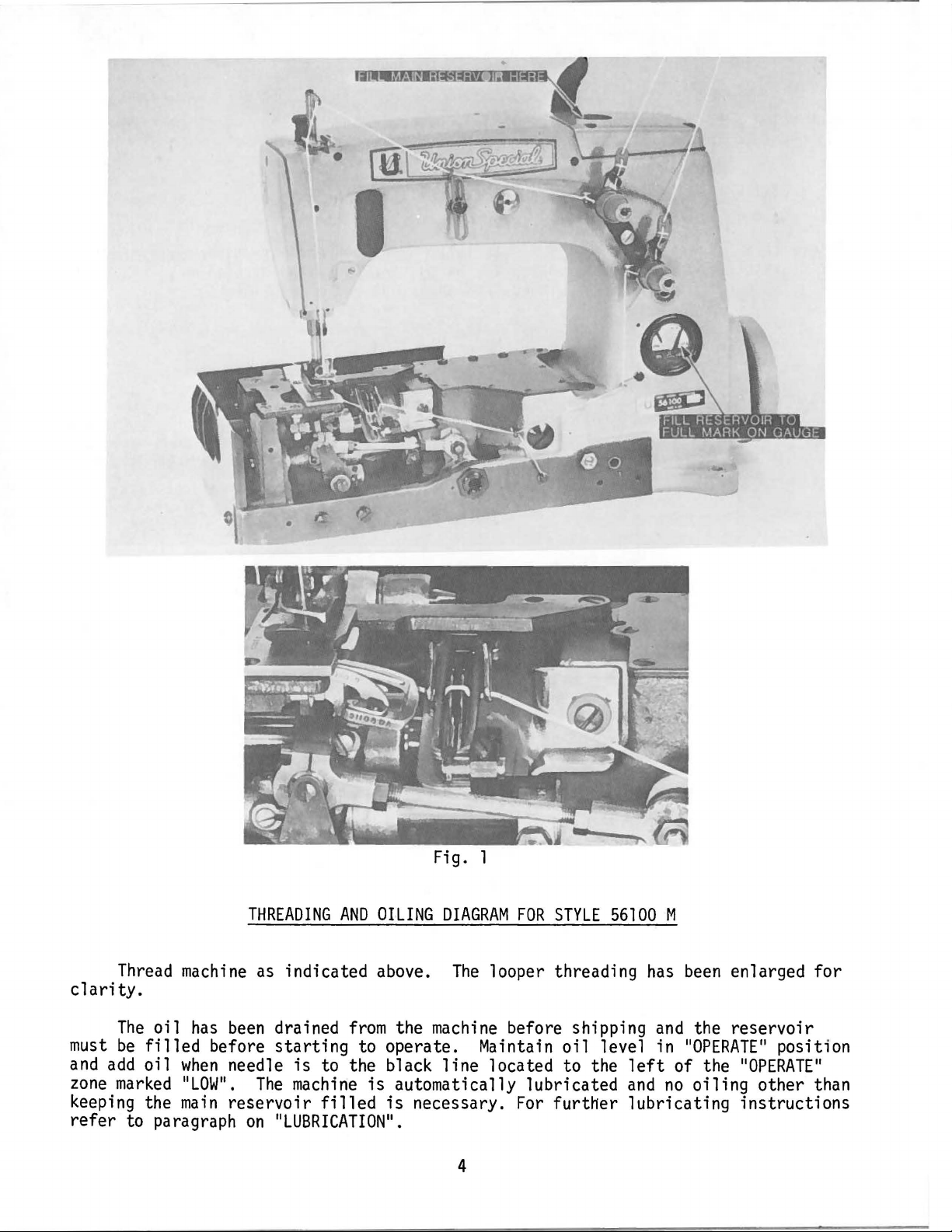
Fig. 1
Thread
machine
THREADING
as
indicated above.
AND
OILING
DIAGRAM
The
FOR
looper threading
STYLE
clarity.
The
oil
has
been
must
and
zone
be
filled
add
oil
marked
keeping the
refer
to paragraph
before
when
''LOW
main
drained
starting
needle
11
•
The
is
machine
reservoir
on 11LUBRICATION
from
the
machine
to operate. Maintain
to the black
is
automatically lubricated
filled
is
11
line
necessary.
•
4
before shipping
oil
located to the
For
further
56100
level in 110PERATE
M
has
been
and
the reservoir
left
of the 110PERATE
and
no
oiling
lubricating
enlarged for
11
other than
instructions
position
11
Page 5
TO
PREVENT
-
All
justing
-
Wear
-
All
THIS
SAFETY
PERSONAL
power
sources to the
or replacing
safety glasses.
shields
and
guards
SYMBOL
INJURY:
machine
parts.
MUST
SAFETY
RULES
A
CAUTION
INDICATES
be
in position before operating machine.
YOUR
MUST
PERSONAL
be
TURNED
SAFETY
OFF
before threading,
IS
INVOLVED.
oiling,
ad-
-DO
NOT
tamper
Use a straight
degrees
F.
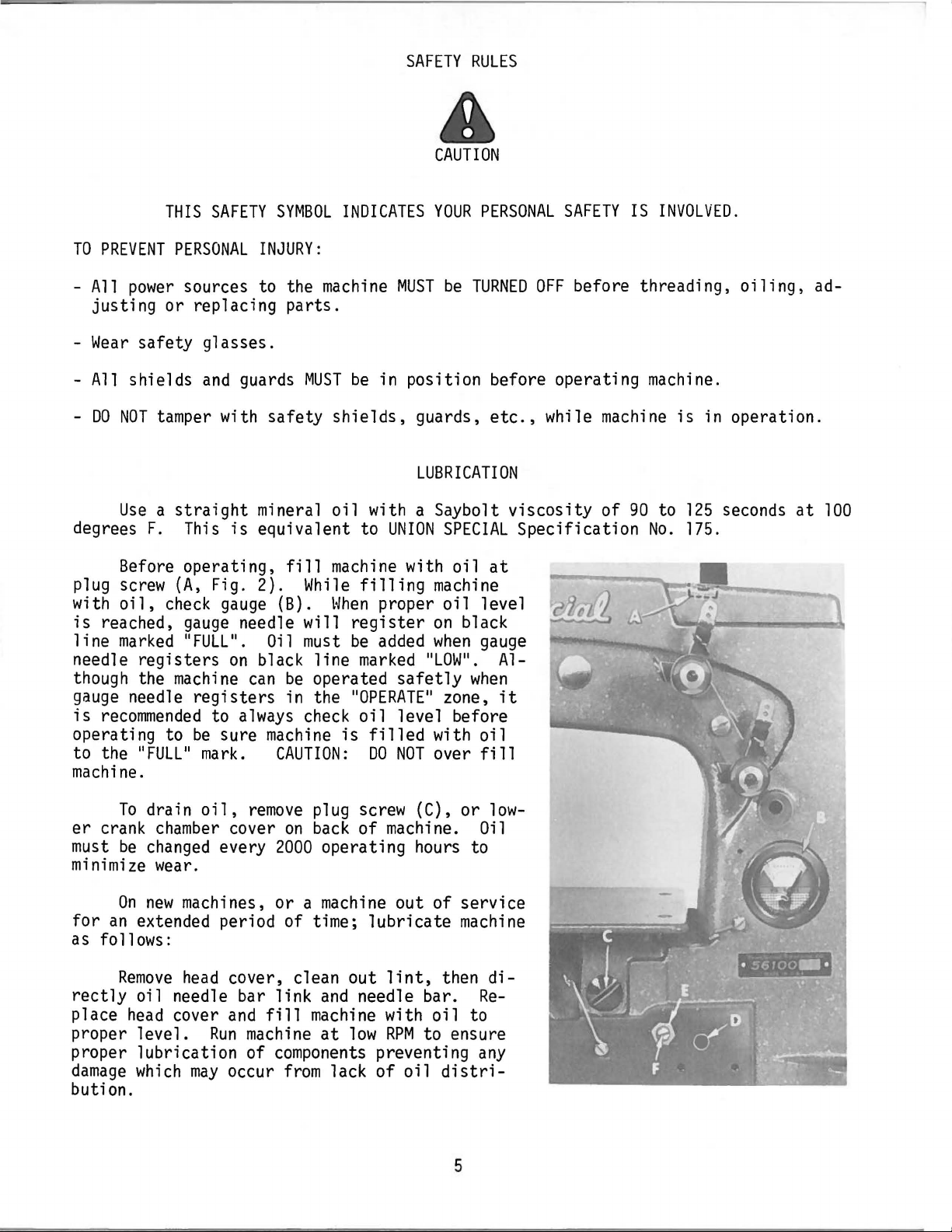
Before operating,
plug
screw
with
oil,
is
reached,
line
marked 11FULL
needle
though
gauge
is
needle
recommended
(A,
check
registers
the
machine
operating to
to the 11FULL
machine.
To
drain
er
crank
must
minimize
be
changed
chamber
wear.
with safety
This
is
Fig. 2).
gauge
gauge
needle will
11
•
on
registers
to
always
be
sure
11
mark.
oil,
cover
every
shields,
mineral
oil
equivalent to
fill
machine
While
(B).
When
register
Oil
black
can
must
be
be
line
operated
in the 110PERATE
check
machine
is
CAUTION:
remove
plug screw (C), or
on
back
2000
operating hours to
guards,
LUBRICATION
with a Saybolt
UNION
filling
proper
added
marked 11LOW
oil
filled
DO
SPECIAL
with
oil
machine
oil
on
black
when
11
safetly
11
when
zone,
level before
with
NOT
over
of machine.
etc.,
viscosity
Specification
at
level
gauge
•
Al-
it
oil
fill
low-
Oil
while
machine
of
90
to
No.
is
in operation.
125
seconds
175.
at
100
On
new
for
machines, or a
an
extended period of time;
machine
lubricate
out of service
machine
as follows:
Remove
rectly
place
head
proper level.
proper lubrication of
damage
which
head
cover, clean out
oil needle bar link
cover
and
Run
fill
machine
components
may
occur
from
and
needle bar.
machine
at
low
lack
lint,
with
RPM
then
oil
to ensure
preventing
of
oil
distri-
di-
Re-
to
any
bution.
5
Page 6
To
recalibrate
oil
gauge, follow
OIL
GAUGE
CALIBRATION
instructions
in sequence
as
listed:
- Place
-
Remove
machine
plug
screw
upright
(C,
on
a level surface.
Fig.
2)
and
tip
machine
voir.
Remove
Fill
-
-
Loosen
registers
lower crank
chamber
reservoir until
locknut
on
(E)
and
the black
oil
rotate
line
cover
is
even
on
with
back
calibrating
marked 11LOWU.
of machine.
bottom
screw
- Tighten locknut (E), then replace plug screw
-
Fill
machine
with
oil
until
gauge
SYNCHRONIZING
needle
LOOPER
registers
AND
rection
(A,
with the
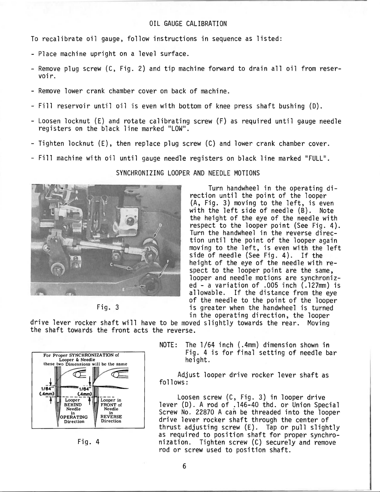
the height
respect to the looper point
Turn
tion
moving
side of needle
height of the
spect to the looper point are the
looper
edallowable.
of the needle to the point
Fig.
3
is
in the operating
drive lever rocker
the
shaft
towards the front acts the reverse.
shaft
will
have
to
be
moved
forward to drain
of
knee
press
(F)
as
required
(C)
and
lower crank
on
black
NEEDLE
Turn
Fig.
the
until
to the
MOTIONS
handwheel
until
3)
left
the point of the looper
moving
side of needle (B).
of
the
handwheel
the point of the looper again
left,
(See
eye
and
needle motions are synchroniz-
all
shaft
until
line
in the operating
to the
eye
of the needle with
in the reverse direc-
is
even
Fig.
of the needle with
a variation of .005 inch
If
the distance
greater
when
the
handwheel
direction,
slightly
towards the
oil
from
bushing
gauge
chamber
reser-
(D).
needle
cover.
marked 11FULL
left,
is
even
Note
(See
Fig. 4).
with the
4).
If
the
same,
(.127mm)
from
of
the
the looper
is
turned
the looper
rear.
Moving
11
•
di-
left
re-
eye
is
For
Prop
Looper
these
two Dimensions
er SYNCHRONIZATION of
& Needle
will be the
NOTE:
same
The
1/64 inch
Fig. 4
height.
is
for final
Adjust looper drive rocker
J
1/84"
(.4mm)
-r
~
-f~~~-l
Needle Needle
OPERATING
Di
1/84"
(.4mm)
in
rection
Fig. 4
J
~
~
----
Looper
in
FRONT of
in
REVERSE
Direction
follows:
Loosen
lever (D). A
Screw
No.
screw
rod
of .146-40 thd. or
22870 A can
drive lever rocker
thrust
as
adjusting screw (E).
required to position
nization. Tighten screw
rod
or
screw
6
used
(.4mm)
dimension
setting
(C,
Fig.
3)
be
threaded into the looper
shaft
through the center of
shaft
{C)
to position
shown
of
needle bar
lever
shaft
in looper drive
Union
Tap
or pull
for
proper synchro-
securely
slightly
and
shaft.
in
as
Special
remove
Page 7
SYNCHRONIZING
LOOPER
AND
NEEDLE
MOTIONS
(Continued)
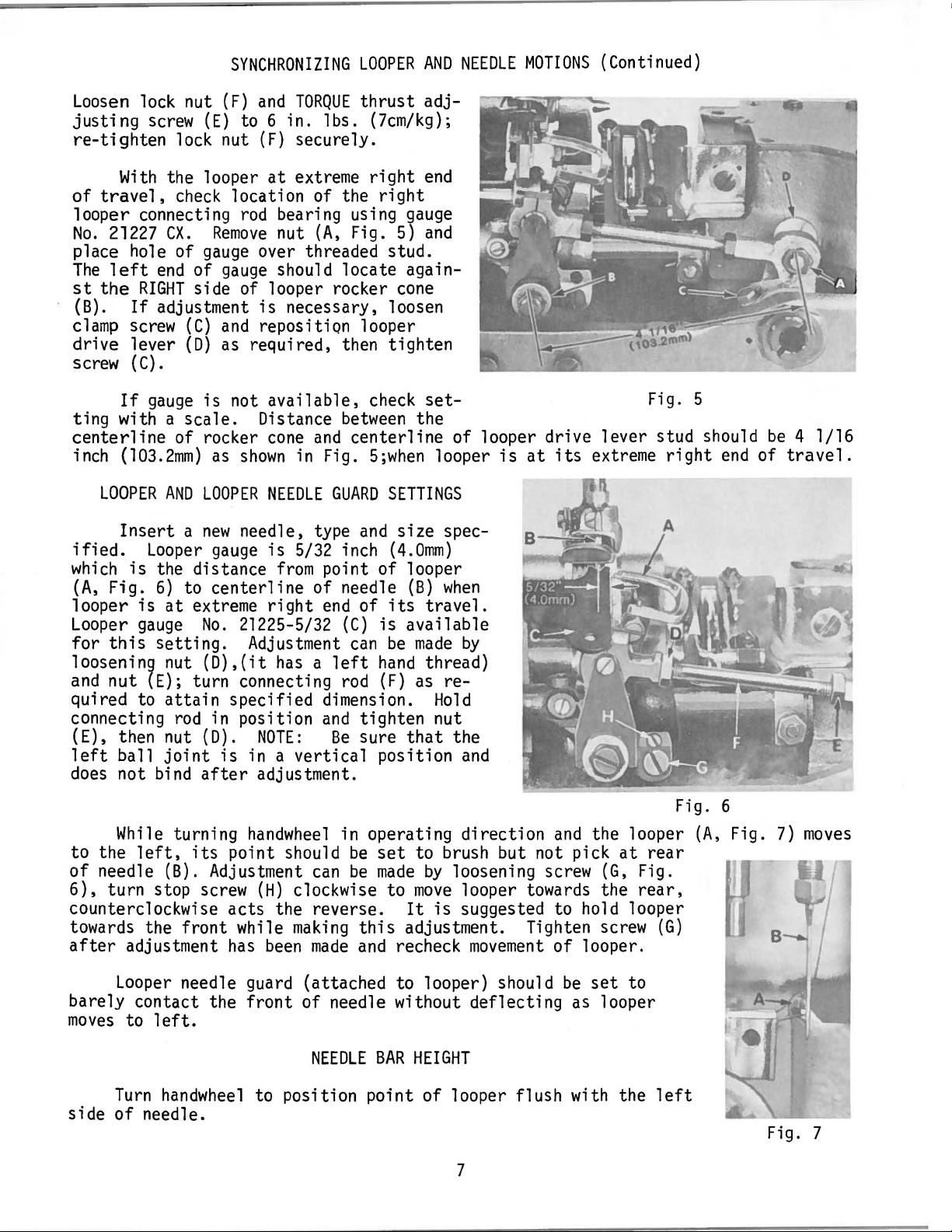
Loosen
justing
re-tighten
of
looper connecting
No.
place hole of
The
st
(B).
clamp
drive lever
screw
ting with a
centerline
inch
ified.
which
(A,
looper
Looper
for
loosening nut
and
quired to
connecting
(E), then nut (D).
left
does
lock nut
screw
With
travel,
21227
left
the
If
LOOPER
Insert a new
Fig.
this
nut (E); turn connecting
ball
not bind
the looper
check
ex.
end
RIGHT
If
adjustment
screw
(C).
gauge
of rocker
(103.2mm)
AND
Looper
is
the distance
6)
is
at
gauge
setting.
attain
rod
joint
(F)
(E)
to 6 in. lbs. (7cm/kg);
lock nut
location of the
rod
Remove
gauge
of
gauge
side of looper rocker
(C)
and
(D)
as required, then tighten
is
not
scale.
as
shown
LOOPER
needle, type
gauge
to
centerline
extreme
No.
21225-5/32
(D),(it
specified dimension.
in position
is
after
and
TORQUE
(F)
securely.
at
extreme
bearing using
nut
over threaded stud.
should locate again-
is
necessary, loosen
reposition looper
available,
Distance
cone
in
NEEDLE
is
5/32 inch
from
of needle
right
Adjustment
has a left
NOTE:
in a
vertical
adjustment.
thrust
right
right
(A,
Fig.
5)
cone
check
between
and
centerline
Fig.
5;when
GUARD
point of looper
end
rod
and
Be
SETTINGS
and
size
(4.0mm)
of
its
(C)
is
can
be
hand
(F)
tighten nut
sure
position
adj-
end
gauge
and
set-
the
of looper drive lever stud should
looper
spec-
(B)
when
travel.
available
made
as
that
by
thread)
re-
Hold
the
and
is
at
its
extreme
Fig. 5
right
end
be
of
4 1/16
travel.
While
to the
of
needle (B). Adjustment
6),
turn stop screw
counterclockwise acts the reverse.
towards the front while
after
barely contact the
moves
side
adjustment
Looper
to
Turn
of
turning
left,
needle.
its
needle guard (attached to looper) should
left.
handwheel
handwheel
point should
(H)
clockwise to
making
has
been
front
to position point
in operating direction
be
can
be
made
of needle without deflecting as looper
NEEDLE
set
made
this
and
BAR
to brush but not pick
by
loosening screw
move
It
is
adjustment. Tighten screw
recheck
HEIGHT
of
looper flush with the
and
looper towards the
suggested to hold looper
movement
7
of
the looper
(G,
looper.
be
set
at
to
Fig. 6
rear
Fig.
rear,
(G)
left
(A,
Fig.
7)
moves
Fig. 7
Page 8
NEEDLE
BAR
(Continued)
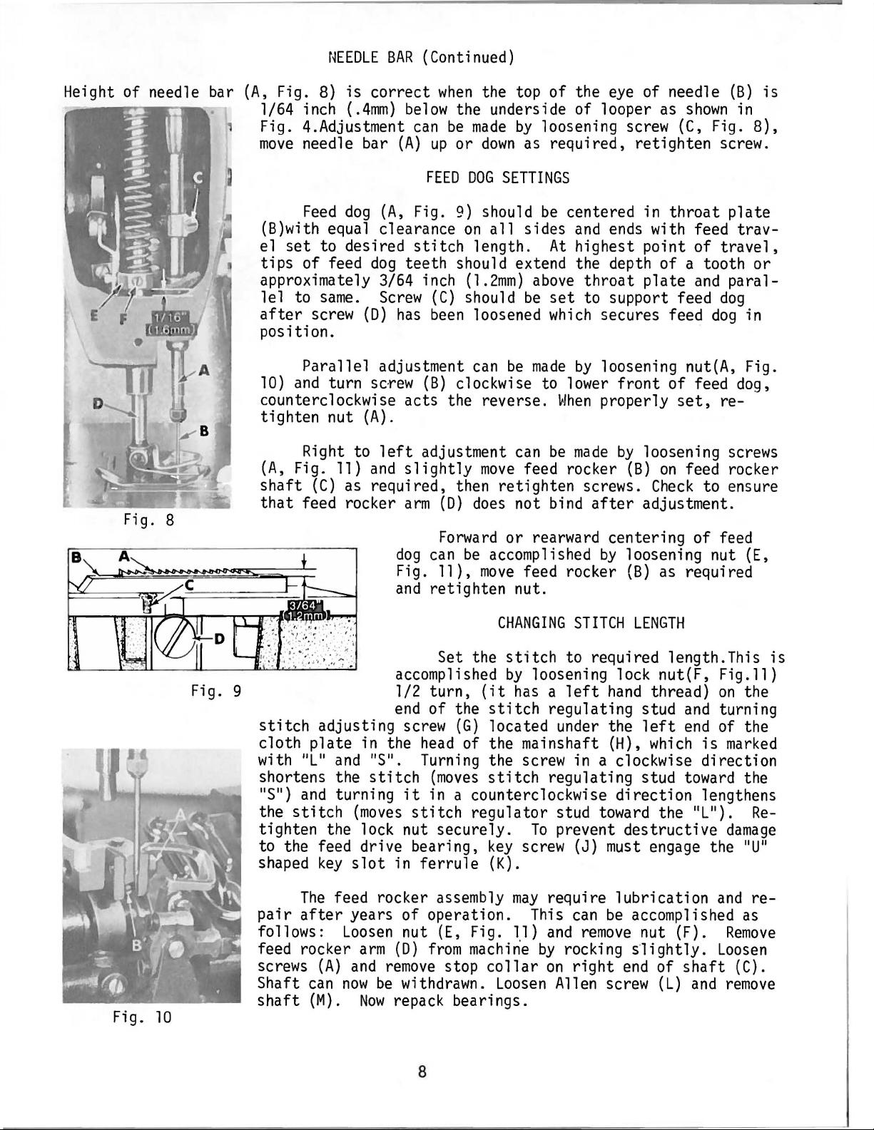
Height of needle bar
Fig. 8
(A,
Fig.
8)
is
correct
1/64 inch
(.4mm)
Fig. 4.Adjustment
move
needle bar
Feed
dog
(A,
(B)with equal clearance
el
set
to desired
tips
of feed
dog
approximately 3/64 inch
lel
to
after
same.
screw
Screw
(D)
below
can
(A)
Fig.
stitch
when
up
FEED
the top of the
the underside of looper
be
made
or
down
DOG
SETTINGS
9)
should
on
all
length.
teeth should extend the depth of a tooth
(1.2mm)
(C)
should
has
been
loosened
position.
Parallel adjustment
10)
and
turn sc·
rew
(B)
can
be
clockwise to lower
counterclockwise acts the reverse.
tighten nut
Right to
(A,
Fig.
shaft
that
(C)
feed rocker
(A).
left
adjustment
11)
and
slightly
as
required, then retighten screws.
arm
dog
can
Fig. 11),
and
retighten nut.
move
(D)
does
Forward
be
accomplished
move
or rearward centering of feed
eye
by
loosening screw
of needle
as
shown
(C,
(B)
in
Fig.
as required, retighten screw.
be
centered in
sides
be
and
At
highest point of
above
throat
set
to support feed
which
made
by
When
can
be
made
feed rocker
not bind
after
feed rocker
ends
secures feed
loosening nut(A, Fig.
front
properly
by
(B)
by
loosening nut
(B)
throat
with feed
plate
trav-
travel,
plate
and
paral-
dog
dog
of feed dog,
set,
re-
loosening screws
on
feed rocker
Check
to ensure
adjustment.
as
required
is
8),
or
in
(E,
Fig.
Fig. 9 1/2 turn,
stitch
cloth plate in the
with 11L
shortens the
11
S
the
adjusting screw
11
and 11S
11
)
and
turning
stitch
11
stitch
(moves
tighten the lock nut securely.
to the feed drive bearing,
shaped
pair
follows:
feed rocker
screws
Shaft
shaft
key
slot
The
feed rocker assembly
after
years of operation. This
Loosen
arm
(A)
and
remove
can
now
be
(M).
Now
10
CHANGING
Set the
accomplished
end
of the
(G)
head
of the mainshaft (H),
• Turning the screw in a clockwise direction
(moves
it
in a counterclockwise direction lengthens
stitch
in
ferrule
stitch
by
(it
has a left
stitch
located under the
stitch
regulator stud
key
screw
(K).
may
nut
(E,
Fig.
11)
(D)
from
machine
stop
collar
withdrawn.
Loosen
STITCH
LENGTH
to required length.This
loosening lock nut(F,
hand
thread)
regulating stud
left
and
end
which
regulating stud
toward
To
prevent destructive
(J)
must
require
can
and
by
rocking s·
on
right
lubrication
be
accomplished
remove
end
nut (F).
lightly.
Allen screw
toward
the 11L
engage the 11U
of
shaft
(L)
and
Fig.ll)
on
turning
of the
is
marked
11
).
damage
and
Remove
Loosen
(C).
remove
the
the
Re-
11
re-
as
repack bearings.
is
8
Page 9
CHANGING
STITCH
LENGTH
(Continued)
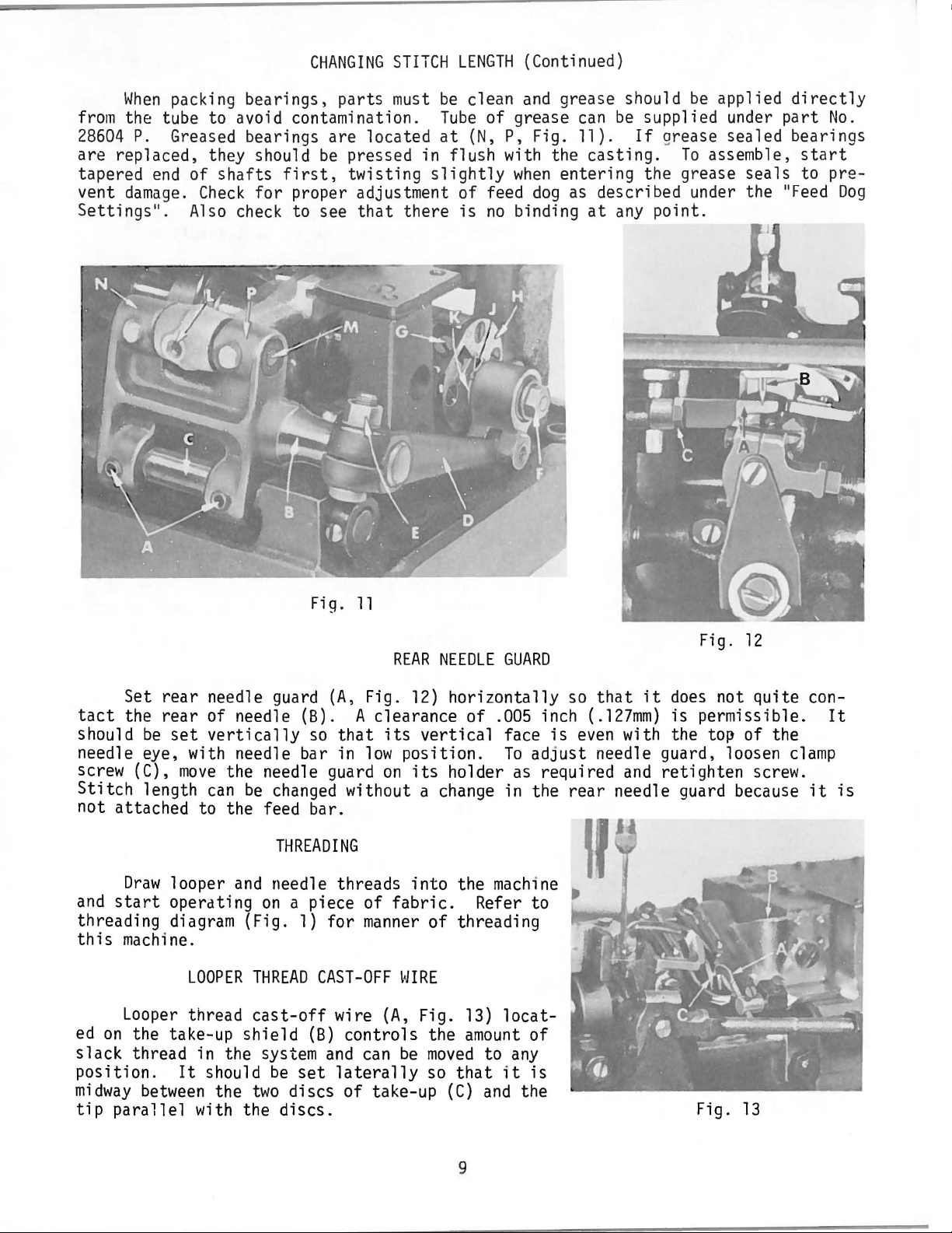
When
from
the tube to avoid contamination.
28604
are
replaced, they should
tapered
vent
damage.
Settings
packing bearings,
P.
Greased bearings are located
end
of
shafts
•
Check
Also
11
parts
be
first,
for
proper adjustment
check to see
must
be
clean
Tube
at
(N,
and
grease should
of grease
P, Fig. 11).
pressed in flush with the
twisting
that
slightly
there
of
is
when
feed
no
binding
entering the grease
dog
be
applied
can
be
supplied under
If
grease sealed bearings
casting.
To
assemble,
seals
as
described under the 11Feed
at
any
point.
directly
part
No.
start
to pre-
Dog
Fig.
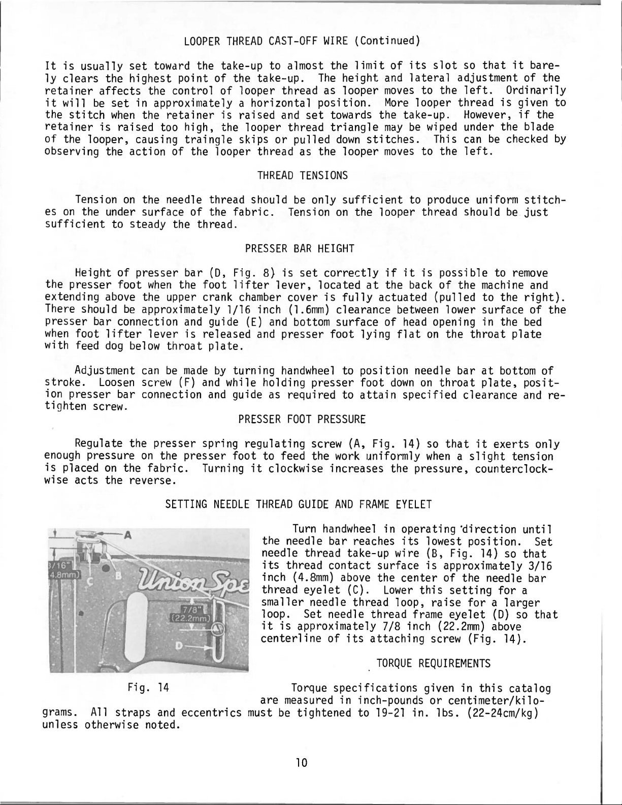
Set
rear
tact
the
should
be
needle guard
rear
of needle (B). A clearance of .005 inch
set
vertically
so
(A,
that
needle eye, with needle bar in
screw (C),
Stitch
move
length
the needle guard
can
be
changed without a change in the
not attached to the feed bar.
THREADING
Draw
and
start
threading diagram (Fig.
this
machine.
Looper
ed
on
slack
position.
midway
tip
parallel
looper
operating
and
needle threads
on
a piece of
1)
LOOPER
thread
the take-up
THREAD
cast-off
shield
thread in the system
It
between
should
the
with the
be
two
set
discs
discs.
for
CAST-OFF
wire
(B)
and
laterally
11
REAR
Fig.
its
low
position.
on
fabric.
manner
WIRE
(A,
controls
can
be
of
take-up
NEEDLE
12)
horizontally
vertical
its
holder
into
the
Refer to
of
threading
Fig. 13)
the
amount
moved
so
that
(C)
GUARD
face
To
as
machine
locat-
of
to
any
it
and
the
so
is
even
adjust
required
rear
is
that
it
(.127mm)
Fig.
does
is
permissible.
not
12
quite
with the top of the
needle guard, loosen
and
retighten
screw.
needle guard because
Fig.
13
con-
clamp
it
It
is
9
Page 10
It
is
usually
ly
clears
retainer
it
will
the
stitch
retainer
be
set
towdrd
the highest point of the take-up.
affects
set
when
is
raised too high, the looper thread
the control of looper thread as looper
in approximately a horizontal position.
the
retainer
of the looper, causing
LOOPER
traingle
THREAD
CAST-OFF
WIRE
the take-up to almost the
The
height
is
raised
and
set
towards the take-up.
triangle
skips or pulled
down
(Continued)
limit
stitches.
observing the action of the looper thread as the looper
of
its
and
lateral
moves
More
may
be
moves
slot
so
that
adjustment of the
to the
left.
looper thread
However,
wiped
This
to the
under the blade
can
be
left.
it
bare-
Ordinarily
is
given to
if
the
checked
by
THREAD
Tension
es
on
the under surface of the
sufficient
on
the needle thread should
to steady the thread.
fabric.
PRESSER
Height of presser bar
the presser foot
extending
above
There should
when
the foot
the upper crank
be
approximately l/16 inch
presser bar connection
when
with feed
stroke.
foot
lifter
dog
Adjustment
Loosen
lever
below
can
screw
throat
be
(F)
ion presser bar connection
and
is
released
made
and
(D,
Fig. 8)
lifter
chamber
guide
(E)
and
and
plate.
by
turning
while holding presser foot
and
guide
as
tighten screw.
PRESSER
Regulate the presser spring regulating screw
enough
is
pressure
placed
on
the
on
the presser foot to feed the
fabric.
Turning
it
clockwise increases the pressure, counterclock-
wise acts the reverse.
TENSIONS
be
Tension
BAR
is
set
lever,
cover
(l.6mm)
only
sufficient
on
the looper thread should
HEIGHT
correctly
located
is
fully
clearance
at
bottom surface of
presser foot lying
handwheel
required to
FOOT
to position needle bar
attain
PRESSURE
(A,
Fig.
work
uniformly
to produce uniform
be
if
it
is
the
possible to
back
of
the
remove
machine
actuated (pulled to the
between
head
flat
down
lower surface of the
opening in the
on
the
throat
at
bottom
on
throat
plate,
plate
specified clearance
14)
so
that
it
exerts only
when a slight
tension
stitchjust
and
right).
bed
of
positand
re-
SETTING
NEEDLE
THREAD
GUIDE
Turn
AND
FRAME
handwheel
the needle bar reaches
needle thread take-up wire (8, Fig.
its
thread contact surface
inch
thread
(4.8mm)
eyelet
above
(C).
smaller needle thread loop,
loop. Set needle thread
it
is
approximately 7/8 inch
grams.
All
Fig.
straps
14
and
eccentrics
centerline
are
measured
must
be
Torque
tightened to
of
its
specifications
in inch-pounds or centimeter/kilo-
unless otherwise noted.
10
EYELET
in operating
its
lowest position. Set
is
~irection
14)
so
until
that
approximately 3/16
the center of the needle bar
Lower
this
raise
frame
setting
for a larger
eyelet
(22.2mm)
for a
(D)
above
so
attaching screw (Fig. 14).
TORQUE
19-21
REQUIREMENTS
given in
in.
lbs.
this
(22-24cm/kg)
catalog
that
Page 11

All
nuts,
tightly
bolts,
as
possible, unless otherwise noted. Special torque specifications
necting rods,
screws,
links,
etc.,
screws,
TORQUE
REQUIREMENTS
without torque
etc.,
are
shown
(Continued)
specifications
on
part
illustrations.
must
be
secured
of
as
con-
When
adjusting needle lever or replacing related
sequence as
l.
Install
needle lever stud
(C).
2.
With
positioned properly;
through hole
parts,
follow
listed:
"0"
rings
needle lever
in
needle lever until
instructions
(A,
Fig.
(B)
and
(D)
in
machine
insert
shoulder contacts the needle lever
the
3.
word
position.
exists
stud
top of
Install
ring
"UP"
on
stud
While
making
in the needle bar
{B) with the
machine
front
bed.
temper load ring
and
cups
through opening in
is
sure
set
SPECIAL
INSTRUCTIONS
NEEDLE
in
15)
onto
thrust
collar
and
stud (B)
its
and
in the upright
no
binding
link,
secure
screw in
(E)
and
compression
machine
LEVER
cups
bed.
(F)
onto stud
Fig.
15
(B),
then
push
4.
Install
Compress
thrust
collar
components
against stud (B). Secure stud
bed.
5.
To
check
compression,
stud
top of
spring out
.
18mm).
temper
(B)
and
bed.
Compress
remove
loosen
Thrust
.003-
load ring
.007 inch
load ring in reverse
order, then tighten
6.
With
oiler
supply hole
and
positions,
will
indented
upright
(J)
position,
so
"UP"
its
(K)
stud are secured in
the proper
be
channeled to stud
on
install
hook
of stud.
cating needle lever
As
couplings
must
align with the
viewed
must
looking
down
align with the spots in the looper drive crank (B)
flats
(C)
onto stud (B) being careful not to
together
for
screw
rear
collar
rear
{G)
set
(C)
set
stud (B) in
bearing
sets
in
When
their
amount
for
(D).
ALIGNING
from
on
crankshaft
by
tighening screw
(B)
in position using the rear
(G)
until washer
proper
from
screw in
should
(.08-
screw.
oil
hook
proper
of
oil
lubri-
MAINSHAFT
TO
CRANKSHAFT
rear of machine, spot screws
(D)
and
mainshaft (E).
Fig.
(A.
damage
(H)
set
screw
16
Fig.
16)
and
set
"0"
ring.
bottoms
in
in
screws
top of
the
(C)
ll
Page 12

ALIGNING
MAINSHAFT
TO
CRANKSHAFT
(Continued)
Fig.
.045"
17
( 1. 14mm)
•
Mainshaft
with
the
right
casting
be
positioned
(.8mm)
(E)
as
tings are
the couplings are tightened
ing sequence
must
.045
inch
side
as
Looper
be
positioned
(1.14mm)
of
its
head
shown
in Fig. 17.
drive crank (8, Fig.
laterally
clearance
shown
made,
between
in Fig. 16.
it
is
very important
for
best performance.
Tighten spot screws
laterally
clearance
and
the
16)
with l/32 inch
it
and
mainshaft
Once
(A)
these
in
the follow-
temporarily,
to the looper drive crank. Tighten
screws
and
21
screws
screws
em/kg), then, torque screws
19-21
(C)
mainshaft.
in.
lbs.
(A)
and
(F)
to
in.
temporarily, to the crankshaft
Torque
(22 -24
set
19 -21
lbs.
(22-
screws
em/kg).
(F)
Loosen
screws (C). Re-torque
in.
lbs.
24cm/kg)
(22 -24
(A
and
.
between
bed
must
setthat
set
to
19
spot
C)
to
-
Fig.
18
CD
•
ed
·
in the
tioned with
out in the
as
possible without touching.
elongated
usted
of the
tion
The
oil
drip plate
oil
reservoir should
its
tip
bed
casting,
mounting
by
loosening (2) screws
oil
reservoir
as
required, retighten screws.
holes
{A,
in the recessed cut
as
far
and
back
cover to posi-
Fig.l8)
be
posi-
to the
It
has
can
be
(B)
in top
locat-
left
adj-
12
Page 13

Before
this
satisfaction
and
is
not
to you.
machine
and
sewing
left
the factory
durability
at
all
it
times.
properly, see the chart
was
below
adjusted
If,
however,
for
and
inspected to give
the
machine
suggestions
which
has
been
may
you
the utmost
readjusted
prove
beneficial
Needle
Condition
loop
too
small
SKIPPED
Frame
set
Needle
bottom
formed
The
because
needle
Needle
needle thread guide
too
low
thread stretched
of
till
needle thread creased
it
is
thread pinched
STITCHES
Causes
stroke,
stretch
is
too
Raise
guide
at
Lower
loop not and/or reduce needle tension
relieved
Use
tight
and
lower
Cures
frame
slightly.
frame
oversize ball
frame
hot reduce tension
by
Drop
needle
needle guard, collapsing
needle loop
Thread
twisting a
round
Keep
needle
needle possible,
tension to a
left
twist thread
Needle
needle grooves,
thread
sticking
due
to heat
in
Use
lubricant
I
needle thread
thread eyelet
eye
needle
guard
loop
keep
eyelet,
slightly
as
small
needle thread
minimum.
on
thread
needle,
as
Use
a
Looper
misses needle loop
as presser foot
off a seam
Needle
but brushed
·
by
Looper
when
match
Needle
loop
formed
out of the
looper
misses needle loop
operator
seams
or
misses
looper thread
is
coming
properly
is
trying to
ends
triangle
side
way
on
Needle
to
Material
front
Needle
does
not
form
needle loop properly
is
not held
of
seam
deflecting
operator
Needle
Needle
erator
back
matching
bar
set
deflecting
who
may
on
material while feed
seams
garment
Looper
thread too loose, not Increase looper thread
making a good
Needle
the rear
point or
pulling
being deflected to
by
burr
due
to operator
on
material,
needle glancing
coming
on a seam
rise
and
is
towards
too high
toward
be
holding
or
ends
triangle
on
needle back.
off
when
enough
Increase looper
to 1/32 inch
down
in
See
if
presser bar
flagging ing
Use
sharp point needle
op-
Lower
Do
on
needle bar
not hold
material. Properly adjust
and
maintain a proper
of feeding pressure
operator
does
tension
Do
not pull material
Use
stop needle
or
off
seam.
burr
gauge
is
l/64
stick-
slightly
back
excessively
on
foot
so
not hold
at
back
the
a sharp needle to
from
glancing
Check
needle
for
NOTE:
More
detailed information concerning the double locked
available under "Stitch Formation,
Type
401".
13
stitch
(stitch
type
401)
is
Page 14

ILLUSTRATIONS
ORDERING
REPAIR
PARTS
This catalog
views
in
be
of various sections of the
their
actual
found a listing
has
been
position
of the
of pieces required in the
Numbers
position
ordering
Component
cated
ly.
48
49
50
51
52
by
Example:
29105
22587
56343
56343
22559
It
will
ing are not
not
recommended,
At
in
this
book.
only the
in the
of
that
parts.
parts
indenting
AK
K
c
E
A
be
listed.
the
back
This will
part
number
first
part
in the
Always
of sub-assemblies
their
Crank
noted in the
The
so
the complete sub-assembly should
of
the
is
arranged to simplify ordering
mechanism
in the machine.
parts
with
particular
column
are reference
illustration.
use
the
part
descriptions
their
view
number
are
shown
On
the
page
part
numbers,
being
shown.
numbers
Reference
listed
which
can
be
under the description
Assembly, looper driving
Screw,
beari~g
Guide, ball
Splasher,
Screw, bearing
reason
book
above
will
example
is
be
facilitate
cap
(upper)
joint--------------------------------------
oil
-----------------------------------------cap
(lower)
that
that
replacement
found
a numerical index of
locating the
the
illustration
known.
repair
so
that
opposite the
descriptions
only,
numbers
in the second
furnished
parts.
the
parts
illustration
and
and
merely
should never
column.
for
repairs
of
the
main
Exploded
may
the
indicate
be
are
sub-assemb-
lever------------------------
-----------------------------
-----------------------------
eccentric,
of
these
be
ordered.
ball
parts
all
and
description
stud,
and
individually
the
parts
be
used
seen
will
number
the
in
indi-
1
2
1
1
2
bear-
is
shown
when
some
Where
of the smaller
the construction permits, each
identification
Part
numbers
pear.
IMPORTANT!
WHICH
PART
IS
Success in the operation of these machines
UNION
sidiaries
proved
cy
SPECIAL
scientific
and
durability
and
Prices are net cash
forwarded
wise
directed.
f.o.b.
parts,
letter
is
represent the
ON
ALL
and
on
stamped
ORDERS,
IDENTIFYING
those
in to
same
PLEASE
where
distinguish
part,
INCLUDE
PARTS
part
is
stamped with
construction
regardless
PART
the
part
of
NAME
its
does
not permit,
from
similar
catalog in
AND
STYLE
part
OF
ORDERED.
USE
repair
parts
authorized
principles,
GENUINE
as
furnished
distributors.
and
are
REPAIR
by
They
made
with utmost
PARTS
can
be
secured only with genuine
the
Union
Special Corporation,
are designed according to the
precision.
Maximum
are assured.
TERMS
and
subject to change without
notice.
All
shipping point. Parcel Post shipments are insured unless
A charge
is
made
to cover postage
and
insurance.
number.
an
ones.
which
they ap-
MACHINE
its
FOR
sub-
most
ap-
efficien-
shipments are
other-
On
14
Page 15

EXPLODED
VIEHS
AND
DESCRIPTION
OF
PARTS
15
Page 16

®~
54~
58
-
_,
21
16
Page 17

MAIN
FRAME,
CAST-OFF
PLATE
AND
MISCELLANEOUS
COVERS
Ref.
10
ll
12
13
14
15
16
17
18
19
20
21
22
23
24
25
26
27
28
29
30
31
32
33
34
35
36
37
38
39
40
41
42
43
44
45
46
47
*48
49
50
51
52
53
54
55
56
57
58
59
60
61
62
63
64
65
66
67
*
No.
l
2
3
4
5
6
7
8
9
For
old Style
Part
No.
22829
21375
98
52
22593
51158
51104
50-216 Blk.
51157
21657
22528
J87 J
77
51204
51104
51204
22798
51204
52958
25
51482
22569
56382
56382
56382
22585
56393
7947
56393
35731
51294
660-342
22513
95
660-694
22889
539
20
22848
22894
56382
56382
22548
56382
56382
22524
22585
22839
51124
87
56180
51280
22570
56168
51125
906
22829
56382
56382
59493
666-214
22848
56382
56382
56382
56382
22524
AV
A
A
D
F
H
E
c
H
A
A
B
s
A
c
A
N
D
c
A
R
A
E
E
D
H
G
A
D
B
J
A
E
J
A
AA
L
y
AB
56180
Screw
----------------------------------------------------------------------Guard,
Screw
Eyelet,
Screw
Eyelet, take-up
Wire,
Pin,
Support,
Washer
Screw
Screw
Screw
Support, auxiliary
Cast-off,
Support,
Screw
Wire,
Eyelet,
Screw
Guard
Screw
Cover,
Gasket
Screw
Clamp,
Nut
Block,
Plate,
Screw
Lockwasher
Screw
Screw, plug
belt
-----------------------------------------------------------------
----------------------------------------------------------------------frame
looper thread
-----------------------------------------------------------------------
-------------------------------------------------------------
cast-off
dowel
---------------------------------------------------~----------
------------------------------------------------------------------
cast-off
----------------------------------------------------------------------
-----------------------------------------------------------------------
-----------------------------------------------------------------------
-----------------------------------------------------------------------
auxiliary---------------------------------------------------------
cast-off
----------------------------------------------------------------------cast-off
frame
--------------------------------------------------------------
looper thread
-----------------------------------------------------------------------
-----------------------------------------------------------------------
----------------------------------------------------------------------head
Felt-------------------------------------------------------------------
-----------------------------------------------------------------
----------------------------------------------------------------------
-----------------------------------------------------------------------
head
oil
tube
------------------------------------------------------------------------head
oil
tube
presser bar connection guide
-----------------------------------------------------------------------
------------------------------------------------------------------
-----------------------------------------------------------------------
-----------------------------------------------------------------
Gasket, needle lever eyelet
Screw, adapter
Eyelet,
Washer
Screw
Screw, needle lever
Gasket
frame
----------------------------------------------------------------------
-----------------------------------------------------------------------
----------------------------------------------------------------------
--------------------------------------------------------------
needle thread
Cover, lower crank
Screw
----------------------------------------------------------------------Gasket
Cover, top
Screw
Screw
Screw,
Throat Plate
Screw
Support,
Screw
---------------------------------------------------------------------oil
reservoir
-----------------------------------------------------------------------
----------------------------------------------------------------------throat
plate
----------------------------------------------------------------
-----------------------------------------------------------------------
throat
Pin,
plate
dowel
-------------------------------------------------------------
-----------------------------------------------------------------------
Holder, needle guard
Guard, needle
Screw
Screw
----------------------------------------------------
---------------------------------------------------------------
------------------------------------------------------------------
Cover, looper drive
Gasket
Pump
Screw
Cover, back,
Gasket
Block, clamping
Plate,
Screw
A,
use
----------------------------------------------------------------------
Assembly,
Felt
oil,
-------------------------------------------------------------------
-----------------------------------------------------------------------
oil
reservoir
----------------------------------------------------------------------
-------------------------------------------------------------
oil
drip
-------------------------------------------------------------
-----------------------------------------------------------------------
countersunk
head
Description
-------------------------------------------------
wire
------------------------------------------------------
cast-off-------------------------------------------------
wire
------------------------------------------------------
-------------------------------------------------
--------------------------------------------------------
mounting
-----------------------------------------------
-----------------------------------------
----------------------------------·
·
--------------
-------------------------------------------------
thrust
chamber
collar
and
stud
----------------------------------
---------------------··----------------------------
----------------------------------------------------
support
-------------------------------------------------
-------------------------------------------------------
--------------------------------------------------------
·
shaft
---------------------------------------------------
-------------------
base----------------------------------------------------
--------------------------------------------------
screw
No.
80.
Amt.
~
2
l
2
l
2
2
l
2
l
1
l
2
l
l
1
1
l
l
l
2
1
2
l
l
1
l
l
l
l
2
l
l
3
l
l
l
l
l
l
2
l
l
4
l
l
8
3
3
l
2
l
2
l
l
l
l
2
l
l
l
l
9
l
l
l
l
2
17
Page 18

16
\
1~1\_
lp
l
~
-l
I
18
Page 19

MAIN
FRAME,
BUSHINGS,
OIL
GAUGE
AND
MISCELLANEOUS
OILING
PARTS
Ref.
No
1
2
3
4
5
6
7
8
9
10
11
12
13
14
15
16
17
18
19
20
\
21
22
23
24
25
26
27
28
29
30
31
32
33
34
35
36
37
38
39
40
41
42
43
44
45
46
47
48
49
50
51
52
53
54
55
56
57
.
22
22539
56394
11635
61256
56394
56394
63494
63494
63494
56390
57890
22569
56390
56390
56382
56382
56382
22541
22733
56382
56301
22839
56381-219
51281
35772
22760
22845
22848
51282
56170
51154
56393
56393
56393
56154
51257
57836
56390
56193
52942
56190
57842
35897
56390
21657
Part
No.
793
R
A
B
660-221
G
c
B
K
660-455
G
F
E
B
B
H
660-665
J
AC
90
c
B
c
E
M
c
24
X
25
AC
H
A
B
80
20
AH
E
95
w
T
.L
AA
B
666-259
50-895
A
w
B
BV
G
X
Blk.
Description
Screw
Screw, plug
Shaft,
Nut
"0"
Washer
Float
Rod,
Gauge
Gasket
Housing, crankshaft bushing, includes bushing
Screw
Washer,
Bearing, needle,
Ring,
Plate,
Screw
Gaske
Cover, upper crank
Screw
Screw, plug
Gasket
Cloth Plate
Screw
Guide,
Screw
Cover, cloth
Screw
Screw
Washer
Shield,
Wire, needle thread take-up
Bushing, needle bar (upper)
---------------------------------------------------
---------------------------------------------
oil
gauge
adjusting
------------------------------
----------------------------------------------------Ring
------------------------------------------------
--------------------------------------------------
Assembly,
oil
gauge
Assembly,
Ring,
Washer,
Nut
------------------------------------------------
oil
gauge
connecting
oil
-------------------------------------
oil
------------------------------------------
spring
-------------------------------------
-------------------------------
-------------------------------
--------------------------------------------------
-----------
--------------------------------------------------thrust
pilot
oil
-----------------------------------------thrust
---------------------------------
---------------------------------------------
and
baffle
-----------------------------------
---------------------------------------------------
t -
------------------------------------------------chamber
------------------------------
---------------------------------------------------
---------------------------------------------
------------------
-
-------------------------------
---------------------------------------------
--------------------------------------------------edge
---------------------------------------------
---------------------------------------------------
plate
Spring
Wa
Screw
Screw
---------------------------------------------
sher, spring
----------------------------------------------
----------------------------------------------
--------------------------------------
-------------------------------------
---------------------------------------------------
---------------------------------------------------
--------------------------------------------------
oil,
end
and
back-------------------------------
-----------------------------
-----------------------------
Screw -·--------------------------------------------------
Pad,
felt
Pump
Bushing, needle bar (lower)
Bushing, presser bar (lower)
Bushing, feed rocker
Bushing, mainshaft
Felt
Bushing, looper rocker
Felt,
Bushing, looper drive
Bushing, mainshaft (intermediate)
Bushing, looper drive lever
Filter,
Bushing, mainshaft (inner
Bushing, tension release
------------------------------------·-----------
Assembly,
Fe
l t
oil,
head--------------------------------
-----------------------------------------------
-----------------------------
----------------------------
shaft
(left)
------------------------------
-------------------------------
---------------------------------------------------machine
base
shaft
(front)
lever
----------------------------
-----------------------------shaft
(front)
---------------
-----------------------
oil
intake
shaft
-------------------------------------right)
lever
(rear)
----------------
------------------------
shaft
--------------------
Amt.
~
1
1
1
1
1
2
1
1
1
1
1
1
1
3
4
2
2
1
2
1
1
4
1
2
1
2
1
2
1
1
3
3
1
3
3
3
1
1
1
1
1
1
1
1
1
2
· 1
1
2
1
1
1
1
1
1
1
19
Page 20

~~
2
6
0 9
78
'
0
10
11
12
~11
TORQUE
19-21
in.
(22-24
em/kg)
TO
Ibs.
1
~
13
NOTE:
C
ut-out
and
aRse
43
mblin
to
in
Ref.
be
up
No.
when
9
42
20
Page 21

CRANKSHAFT,
NEEDLE
LEVER
AND
LOOPER
DRIVING
PARTS
Ref.
No.
1
2
3
4
5
6
7
8
9
10
11
12
13
14
15
16
17
18
19
20
21
22
23
24
25
26
27
28
29
30
31
32
33
34
35
36
37
38
39
40
41
42
43
44
45
46
47
48
49
50
51
52
53
54
55
56
57
58
59
60
61
Part
No.
56
51217
27-435
56358
22768
22586
51250
51250
660-625
56350
56350
660-614
29348
77
56354
51254
22562
22564
52336
W0-3
660-215
56350
29066
22599
51216
51216
56316
22574
61321
57821
56321
22894
660-202
57847
95
51247
22894
29476
51216
51216
51216
56316
12934
22894
22894
56343
22653
29105
22587
56343
56343
22559
52942
660-202
56390
660-665
56390
56342
CL-21
52942
56342
c
R
F
D
E
F
AF
D
K
A
A
D
R
G
N
p
L
N
AB
J
LN
M-625
M-626
M-627
c
A
c
D
F
L-8
AK
K
c
E
A
AA
H
J
E
AC
D
Blk.
Description
Nut
----------------------------------------------------------------Needle
Washer,
Eyelet, needle bar thread
Screw
Screw
Gasket
Washer
"0"
Collar, needle
Cup,
Ring, temper load
Lever Assembly, needle
Ball
Washer
Nut
Connecting
Screw
Plate,
Handwheel
Pulley
"0"
Collar,
Counterweight
Crankshaft Sub-Assembly, .990 inch
Guide, connecting rod
Nut
Pump,
Pump,
Screw,
Screw, spot
Coupling
Crank
Shaft, looper drive rocker
"0"
Washer,
Bearing, needle
Ring,
Lever, looper
Wick,
Screw,
Nut
Bar
----------------------------------------------------------
needle bar
---------------------------------------------------------------
---------------------------------------------------------------
--------------------------------------------------------------
--------------------··----------
Ring
-------------------------------------------------··----------
compression
Screw
Link, connecting
Connection, needle bar
Screw
Pin,
Ring,
Stud, needle
joint,
Screw
-----------------------------------------------------------------
Screw
Ring
Screw
Screw
Bearing, needle,
Bearing, needle, .0626 inch
Bearing, needle,
-----------------------------------------------------------------
Screw
Screw, bearing
Guide, ball
Splasher,
Screw, bearing
Ring
-----------------------------------------------------------------
----------------------------------------------------------
Screw
----------------------------------------------------------
link
Yarn
retaining
needle
----------------------------------------------------------
-------------------------------------------------------------Rod,
--------------------------------------------------------------retaining
-----------------------------------------------------------
--------------------------------------------------------------
----------------------------------------------------------
------------------------------------------------------------
thrust
----------------------------------------------------------
----------------------------------------------------------
oil,
head
oil,
base
set
----------------------------------------------------------
---------------------------------------------------------
------------------------------------------------------------
----------------------------------------------------------
Assembly, looper driving
------------------------------------------------------------
thrust
pilot
oil
---------------------------------------------------------
-----------------------------------------------------------
thrust
eyelet
lever
----------------------------------------------------
---------------------------------------------------
-----------------------------------------------------
------------------------------------------------------
-----------------------------------------------------lever
lever
needle
----------------------------------------------------
------------------------------------------------------
-------------------------------------------------------
(See
(See
cap
joint
oil
-------------------------------------------------cap
-----------------------------------------------------thrust
drive,
synchronizing adjusting
-------------------------------------------
-------------------------------------------
-------------------------------
thrust-----------------------------------------
----------------------------------------------
-----------------------------------------------
-----------------------------------------
------------------------------------------------
--------------------------------------------(upper)
lever
.0625 inch
.0627
-----------------------------------------------
Ref.
No.
Ref.
No.
(upper)
---------------------------------------------(lower)
------------------------------------------
----------------------------------------------
marked "D''
------------------------------------
----------------------------------------
(25.15mm)
(1.588mm)
(1.590mm)
inch
(1.593mm)
43
Page
19)
60
Page
17)
lever
--------------------------------
-------------------------------------
-------------------------------------
-------------------------------------
-------------------------------
throw-----------------diameter----------------diameter----------------diameter-----------------
---------------------------
---------------------------
Amt.
~
1
1
1
1
1
1
1
1
2
1
2
1
1
1
1
1
1
1
2
2
4
1
1
2
1
1
2
3
1
1
1
2
1
1
2
1
2
1
28
28
28
1
1
1
1
2
2
2
2
1
2
1
1
2
1
1
4
2
2
1
1
1
1
21
Page 22

22
Page 23

LOOPER
ROCKER
AND
CONNECTING ROD
PARTS
Ref.
No.
1
2
3
4
5
6
7
8
9
10
11
12
13
14
15
16
17
18
19
20
21
22
23
24
25
26
27
28
29
30
31
32
33
34
35
36
37
38
39
40
41
42
43
Part
No.
51244
51216
18
51244
55244
W0-3
57744
C067
56344
51236
56344
719
98
51246
96
22874
29192
51745
56313
15465
88
258
22829
56393
87
57841
22729
269
35741
18
20
18
29476
56341
52942
56342
22882
51242
73
51108
73
51110
18
N
N
L
G
E
B
A
c
v
F
A
J
u
c
A
LV
F
R
E
c
M
DA
A
D
Descri p
Collar, looper rocker
Washer
Nut
Washer,
Stud
Yarn
----------------------------------------------------
----------------------------------·--------------------thrust
----------------------------------~---------
------------------------------------------------------
----------------------------------------------Shaft, looper rocker
Cork
Arm,
Pin, link
Nut
Screw, spot
Screw, lock
Rocker
-----------------------------------------------------looper rocker
-------------------------------------------------
Frame,
looper rocker
Screw, stop
Screw,
set
------------------------------------------
-------------------------------------------
-------------------------------------------------------
-----------------------------------------------
-----------------------------------------------
Assembly, looper
Stud, rocker
cone
Rocker, looper,
Cone,
Nut,
Screw
Oiler,
Screw
Ball
-----------------------------------------------------
Joint,
Screw
Nut,
left
ConneGting
Nut,
right
Washer
Nut
-------------------------------------------------------
looper rocker
Screw
check
-------------------------------------------
-------------------------------------------
------------------------------------------------
looper connecting rod ball
looper connecting rod
------------------------------------------------
hand
thread
Rod,
looper
hand
thread
----------------------------------------------------
Bearing Assembly, looper connecting rod
Ferrule
----------------------------------------------
Stud, looper lever
Lever, looper
Screw
Washer
Screw, looper
Looper
Screw
----------------------------------------------------
-----------------------------------------------------
drive,
------------------------------------------------
-----------------------------------------------
---------------------------------------------
Guard, looper needle
Nut
-------------------------------------------------------
tion
shaft-
--------
----------------
--------------------------------------
shaft
----------------------------------
--------------------------------------
-----------------------------------
------------------------------------
marked 11S
11
---------------------------
----------------------------------
joint
(left)
(left)
------------------
-------------------------------------
------------------------------------
------------------------------------
(right)
---------------------------------------marked 110
11
---------------------------
--------------------------------------
Amt.
~
--
----
1
1
1
2
1
as required
1
1
1
1
1
1
1
1
1
1
1
1
1
1
2
1
1
------------
1
1
1
2
1
1
1
1
1
--------~--
1
1
1
1
1
1
1
1
1
1
1
23
Page 24

24
Page 25

MAINSHAFT
AND
FEED
DRIVING
PARTS
Ref.
No.
1
2
3
4
5
6
7
8
9
10
11
12
13
14
15
16
17
18
19
20
21
22
23
24
25
26
27
28
29
30
31
32
33
34
35
36
37
38
39
40
41
42
43
44
45
46
47
48
49
50
51
52
Part
No.
29476
55235
6042
55235
77
56336
56336
51054
660-149
21657
269
22525
56322
22798
56336
660-269
56336
22543
56122
51-173
56322
22891
29476
22894
77
39543
29476
22894
77
56123
22764
22580
56334
22651
56334
22637
22863
6042
258
56335
98
56335
56334
56335
660-359
22651
660-438
41391
61341
22528
51105
51236
MJ
E
A
D
B
c
E
A
c
c
B
D
B
A
Blk.
B
B
NM-140
AA
N
NM-096
AA
c
D
N
CB-4
L
P-24
c
A
A
D
L
B
G
CD-4
J
G
A
Descri ption
Feed
Rocker
Nut
Washer
Stud, locking
Screw
Arm
and
Feed
---------------------------------------------
------------------------------------------
-----------------------------------
-------------------------------------------
Link, feed crank
Ferrule, feed crank link
Pin, link
Washer
Nut,
Screw
Plate,
Screw
-----------------------------------------------
left
-----------------------------------------------mainshaft
------------------------------------------------
Stud, feed crank,
Ring,
Insert,
Screw,
quad
feed crank stud
stitch
Mainshaft
Plug,
Gasket
Screw
Eccentric
Screw
Screw
Washer,
feed bar
Eccentric
Screw
Screw
---------------------------------------
Wick,
thread
oil
----------------------------------
------------------------------------head
marked 11A
--------------
regulating
-------------------------------------------oil
---------------------------------------
------------------------------------------
-------------------------------------------
Assembly,
feed
-------------------------------------------
------------------------------------------thrust
Assembly,
looper avoid
-------------------------------------------
-------------------------------------------
Take-up, looper thread
Screw, spot
Screw,
Feed
Bar
Screw
Holder, feed d
set
---------------------------------------------
-------------------------------------------
-------------------------------------
--------------------------------------
og
Screw, height adjusting
Screw, holder adjusting
Washer
Nut
------------------------------------------
---------------------------------------------
Collar, feed rocker
Screw
Shaft, feed rocker
Shaft, feed bar
Rocker, feed
-------------------------------------------
-----------------------------------
--------------------------------------
-----------------------------------------
Bearing, needle, with seal
Screw
Ring, retaining
Washer
Washer,
Screw, feed
Feed
Dog,
Pin,
link
-------------------------------------------
--------------------------------------
----------------------------------------------feed bar
marked 11RD
-------------------------------------
dog
--------------------------------------
11
--------------------------------------------
Amt.
~
Crank
Link
Sub-Assembly
1
1
1
1
1
--------------------------------
-------------------
1
1
1
1
1
1
4
-------------------
11
-------------------------
~
----------------------------
------------------------------
-----------------------------
~
------------
1
1
1
1
1
1
1
1
1
1
lift------------------------
1
1
1
------------------------------
---------------------
2
1
1
1
-------------------------------
1
1
1
1
1
--------------------------------
-------------------------
-------------------------
1
1
1
1
1
shaft-----------------------
1
2
1
1
1
----------------------
2
2
1
1
2
1
--------------------------------
1
1
25
Page 26

26
Page 27

PRESSER
FOOT,
LIFTER
LEVER
AND
THREAD
TENSION
PARTS
Ref.
No.
1
2
3
4
5
6
7
8
9
10
11
12
13
14
15
16
17
18
19
20
21
22
23
24
25
26
27
28
29
30
31
32
33
34
35
36
37
38
39
40
41
42
43
Part
No.
43120
43130
22897
57
15480
88
43130
22561
43130
187
51257
531
51257
402
56383
53787
56356
22758
22557
56383
56383
56383
51183
22758
51183
50-703
660-207
39552
53783
22537
43266
51491
80557
52892
22872
51192
51192
56392
109
56392
51292
51292
39592
39592
WD
c
A
B
A
K
M
A
c
G
D
AA
AB
B
c
c
c
N
c
G
B
E
F
F-8
F-2
AK
z
Blk.
Description
Presser
Bar, presser
Screw
Connection
Screw
Link,
Spring, presser
Regulator, presser spring
Screw
Screw
Spring
Bell
Connecting
Lever, presser foot
Screw
Latch, lever
Pin, stop
"o••
Washer
Lever,
Nut
Guide, lead-in
Washer,
Support, tension post
Screw
Eyelet, tension post
Ferrule, tension post
Post, tension
Disc, tension
Shield, thread tension spring
Spring, needle thread tension
Spring, looper thread tension
Ferrule, tension spring
Nut,
Foot
-----------------------------------------
Bottom,
Screw
Screw
Spring
Screw
Shank
Screw
Guard,
Screw
------------------------------------------------
-----------------------------------------------lifter
------------------------------------------------
------------------------------------------------
-----------------------------------------------
Crank, presser foot
------------------------------------------------
Ring
----------------------------------------------internal,
Screw
-------------------------------------------------spacer
------------------------------------------------
tension
presser foot
-------------------------------------------
-------------------------------------------
------------------------------------------
-------------------------------------------
-------------------------------------------
------------------------------------------finger
-------------------------------------------
-----------------------------------------
and
lever-----------------------------------
Rod,
-----------------------------------------
--------------------------------------------
---------------------------------------------
-------------------------------------------
----------------------------------------
----------------------------------------
-----------------------------------------
-----------------------------------
Guide, presser bar
--------------------------------------
presser foot
lifter
presser foot
---------------------------------------
---------------------------------------
---------------------------------
----------------------------
--------------------
----------------------------
lifter
---------------------------
--------------------------------
--------------------------------
------------------------------
lever----------------
lifter
lifter-----------------
------------------------
------------------------
------------------------
lever
------------
Amt.
~
1
1
1
1
1
2
1
1
1
1
1
1
1
1
1
1
1
1
1
1
1
1
1
1
1
1
1
1
1
1
1
2
1
1
1
2
2
2
4
2
1
1
2
2
27
Page 28

6
. .
I
...........
:
..........
I
I -
I
I
I
I
;;
Page 29

THREAD
STAND
AND
ACCESSORIES
Ref.
No. No.
1
2
3
4
5
6
7
8
9
10
11
12
13
14
15
16
Part
821114
22651
21104
21104
21104
21113
21130
22650
21104
21104
21104
22650
21388
116
51295
51295
660-457
28604
A
CD-5
B-9
B-11
E
c
s
CD-4
G
H
c
CE-6
B
A
R
Description
Base, thread stand
Screw
Rod,
Rod,
Connection, spool support
Wire, thread guide
Support,
Pin, spool
Nut,
Connection,
Wrench,
Wrench,
Isolator
Isolator
Cover,
Oil,
thread stand
thread stand
Screw
spool pin
Screw
16
-------------------------------------------
cone
----------------------------------------
-------------------------------------------
------------------------------------------rod
-------------------------------------------
3/8 inch
9/32 inch
---------------------------------------------
---------------------------------------------
dust,
fl.
(not
oz.,
-----------------------------------
------------------------------------
------------------------------------
-----------------------------------
---------------------------------------
-------------------------------------(9.5mm)
(7.lmm)
shown)
Spec. 175, (not
----------------------------
open
end
--------------------
open
end
-------------------
----------------------------shown)--------------
Amt.
~
1
1
1
1
2
2
2
1
2
2
1
2
1
1
3
1
1
1
29
Page 30

N U M E R I C A L I N D E X 0 F P A R T S
Part
No.
W0-3
.........
18
...........
20
...........
CL21.
C067 E .........
..........
24 X .........
25
...........
25
s
.........
27-435
50-216
50-703
50-895
51-173
52
56
57
73
73
77
80
87
87
J87 J .........
88
90
95
96
98
98
109
116
187 A .........
258 A .........
269
402
531
539
719
660-149
660-202
660-207
660-215
660-221
660-269 8
660-342
660-359
660-438
660-455
660-457
660-614
660-625
660-655
B1k
B1k
B1k
B1k
B1k
A
•••••••••
...........
WD
........
...........
A
.........
...........
...........
...........
u
.........
...........
...........
...........
...........
...........
A
•••••••••
...........
...........
...........
...........
...........
...........
...........
.......
.......
.......
.......
.......
.......
.......
.......
.......
.......
.......
.......
.......
...
...
...
...
...
.....
Page
No.
21,23
23
17,19,23
21
19
19
17
21
17
27
19
25
17
21
27
23
23
23
17,21,25
19
17
23
17
23,27
19
17,19,21
23
23,25
17
27
29
27
23,25
23,25
27
27
17
23
25
21
27
21
19
25
17
25
25
19
29
21
21
19,21
Part
No.
660-694
666-214
666-259
906
6042 A ............
7947
11635 B ............
12934 A ............
15465 F ............
15480
21104
21104
21104
21104
21104
21104
21113
821114 A ............
21130
21375
21388
21657 E ............
21657
22513
22524
22525 A ....... : ....
22528
22537
22539
22541
22543
22548
22557
22559 A ............
22561
22562 A ............
22564
22569
22569
22570 A ............
22574
22580
22585
22585 A ............
22586
22587 K ............
22593
22599
22637
22650
22650
22651
..........
..........
..........
..............
..............
c
............
B-9
..........
B-11
.........
c
............
E.
...........
G
••••• · •••••••
H
............
c
............
s
............
AV
...........
..............
X
••••••••••••
..............
..............
..............
..............
R
............
c
............
8
............
..............
G
•••••• : •••••
..............
..............
8
............
c
............
..............
0
............
..............
R
............
..............
G
............
P-24
.........
CD-4
.........
CE-6
.........
CB-4
.........
Page
No.
17
17
19
17
25
17
19
21
23
27
29
29
29
29
29
29
29
29
29
17
29
17,25
19
17
17
25
17,25
27
19
19
25
17
27
21
27
21
21
19
17
17
21
25
17
17
21
21
17
21
25
29
29
25
Part
No.
22651
22651
22653
22729
22733 E ............
22758
22760 A ............
22764
22768
22793
22798 A ............
22798
22829
22839
22839
22845
22848
22863
22872
22874
22882
22889 A ............
22891 B ............
22894
22894 D ............
22894 E ............
22894 J ............
22894
22894
22897
28604
29066
29105
29192
29348
29476
29476
29476
29476
29476
35731 A ............
35741 A ............
35772
35897
39543 N ............
39552
39592
39592
41391.
43120
43130
43130
CD-4
.........
CD-5
.........
L-8
..........
c
............
c
............
c
............
..............
..............
c
............
..............
..............
c
............
8
............
..............
c
............
..............
..............
c
............
c
............
AA
...........
AB
...........
..............
R
............
R
••••••••••••
AK
........•..
v
............
AF
...........
LN
...........
LV
...........
MJ
...........
NM-096
NM-140
H
............
BV
c
............
z
............
AK
.............
..............
..............
. A
............
.......
.......
...........
...........
Page
No.
25
29
21
23
19
27
19
25
21
19
17
25
17,23
17
19
19
1 7 '19
25
27
23
23
17
25
21
21
17
21
25
21
27
29
21
21
23
21
21
23
25
25
25
17
23
19
19
25
27
21
27
25
27
27
27
30
Page 31

N U M E R I C A L I N D E X 0 F P A R T S
Part
No.
43130
43266
51054
B
............
..............
..............
51104 F ............
51104
51105
51108
51110
51124
51125
51154
51157
51158
51183
51183
51192
51192
51204
51204
51204
51216
51216
51216
51216
51216
51217
51236
H
............
G
••••••••••••
DA
•••••••••••
D
............
D
••••••••••••
E
••••••••••••
E
............
H
............
D
............
B
............
c
............
B
............
G
............
..............
A
............
c
............
M-625
M-626
M-627
N
P
c
A
........
........
........
............
••••••••••••
............
•••••.••••••
51242 M ............
51244
51244
51246
51247
51250
L.
...........
N
••••••••••••
..............
..............
0
............
51250 F ....... · .....
51254
51257
K
..•.........
K
......•.....
51257 M ............
51257
51280
51281
51282
51292
51292
51294
51295
51295
51482
51491'
51745
52336
52892 ...
52942
AA
•••••••••••
J
............
AC
•••••••••••
AH
...........
F-2
..........
F-8
..........
R
............
A
••••••••••••
B
............
A
............
c
............
..............
A
............
...........
R
............
Page
No.
27
27
25
17
17
25
23
23
17
17
19
17
17
27
27
27
27
17
17
17
21
21
21
21
,23
21
21
23,25
23
23
23
23
21
21
21
21
27
27
19
17
19
19
27
27
17
29
29
17
27
23
21
27
23
Part
No.
52942
52942
52942
52958
53783
53787
55235
55235
55244
56122
56123
56154
56168
56170
56180
56190
56193
56301
56313
56316
56316
56321
56322
56322
56334
56334
56334
56335
56335
56335
56336
56336
56336
56336
w •••••..•••••
AA
...........
AC
•••••••••••
B
............
N
............
..............
D
............
E
............
G
••••••••••••
A
............
..............
..............
..............
..............
B
............
..............
A
............
..............
..............
..............
c
............
N
............
B
............
c
............
B
............
L
.•••.•.••...
N
............
0
.•...•......
G
••••••••••••
L
............
..............
B
............
c
............
D
............
56341 F ............
56342
56342
56343
56343
56343
56344
56344
56350
56350
0
............
E
............
c
............
E
............
F
••••••.••...
B
••••••••••••
c
............
0
............
E
............
56350 F ............
56354
56356
56358
56381-219
56382
56382
56382
0
............
..............
..............
..........
..............
A
............
B
............
Page
19
21
21
17
27
27
25
25
23
25
25
19
17
19
17
19
19
19
23
21
21
21
25
25
25
25
25
25
25
25
25
25
25
25
23
21
21
21
21
21
23
23
21
21
21
21
27
21
19
17
17
19
No.
,23
Part
No.
56382
56382
56382
c
............
0
............
E
............
56382 G ............
56382
56382
56382
H
............
J
............
L
•....••..•..
56382 M ............
56382
56382
56382
56382
56382
56383
56383
56383
56383
56390
56390
56390
56390
56390
56392
56392
56393
56393
56393
56393
56393
56393
56394
56394
56394
57744
57821
57836
57841.
57842
57847
57890
59493
61256
61321
61341
N
••••••••••
y
............
AA
...........
AB
...........
AC
...••••••.•
A
............
0
............
AA
•.•••••••••
AB
•••••••••••
..............
E
............
G
••••••••••••
H
............
J
............
E
•.••••.•••••
F
............
c
............
0
............
J
............
L.
...........
T
............
w
............
A
............
B
............
c
............
..............
..............
B
............
.............
B
••••••.•••••
..............
B
............
A
............
G
...... · ......
L
••.••.••••••
J
............
63494 F ............
63494
63494
80557
G
............
K
............
..............
19
17
17
17
17
17
17
19
••
17
17
17
17
19
27
27
27
27
19
19
19
19,21
19,21
27
27
17
17
23
19
19
19
19
19
19
23
21
19
23
19
21
19
17
19
21
25
19
19
19
27
Page
No.
31
Page 32

/
WORLDWIDE SALES AND SERVICE
UNION SPECIAL maintains sales and service facilities throughout the world. These offices will aid you
in
the selection of the right sewing equipment for
your particular operation.
sentatives and servicemen are factory trained and
are
able to serve your needs promptly and efficiently.
Whatever your location, there
representative to serve you. Check wi
It
is
important
to
COLUMBIA machines are also products of UNION
SPECIAL,
thus offering the Industry the most com-
plete line of the Finest Quality sewing machines.
Unoon Specoal
Unoon Spec:oal.
Corpora
GmbH.
UNION SPECIAL repre-
is
a UNION SPECIAL
th
remember
liOn , 400 N Franklon
Schwab<tra<,<;e 33 0 -7000
that
LEW IS
him today.
AND
Street
Chocaqo. IL
Slutlq<HI 1 We
Norcross,
Chicago, IL
Dallas,
Commerce, CA
New
Ph
iladelphia,
Woburn,
Opa-Locka, FL
Montreal, Quebec
Toronto, Ontario
Catano. Puerto Rico
Brussels,
Leicester, England
Paris, France
Stuttgart.
Hong Kong
Other Representatives throughout
all parts of the world
60610. US
<;l
Germany
GA
TX
York, NY
MA
Belgium
W.
Germany
A
PA
Pn
nted
on
U S A
 Loading...