

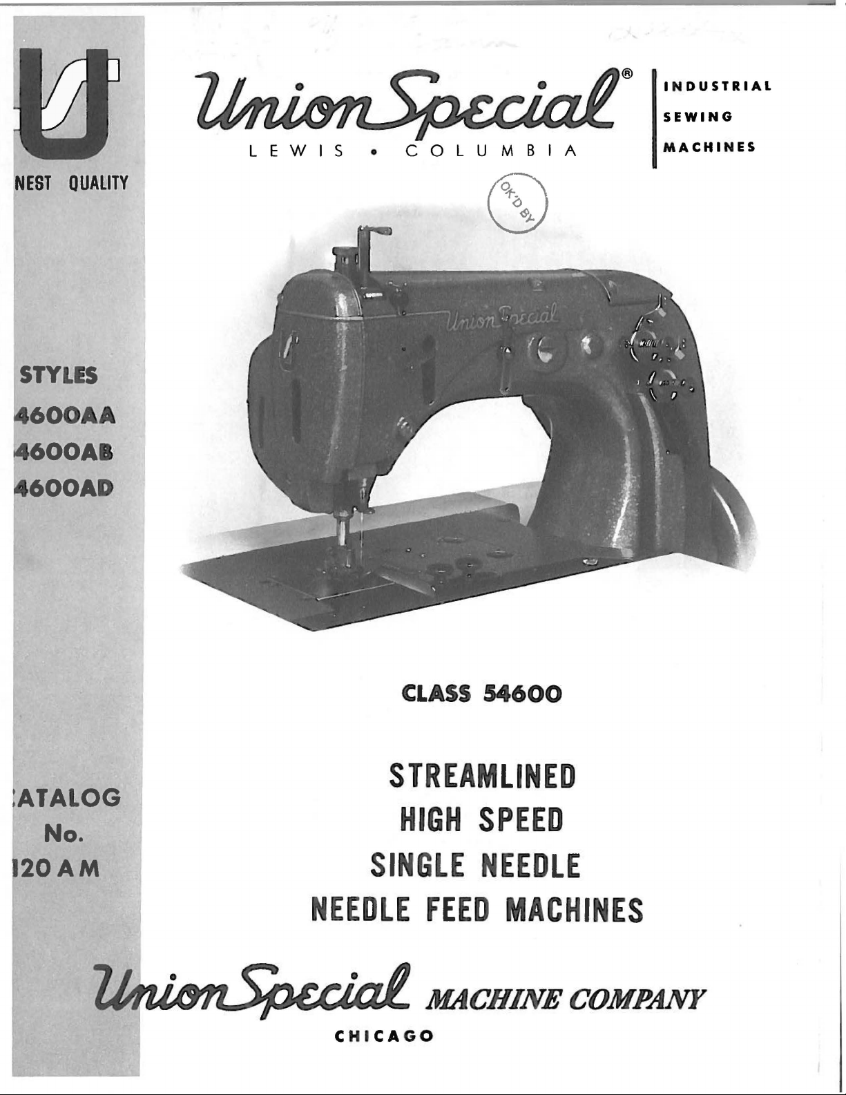
Page 1
®
I N
DUSTRIAL
SEWING
NEST
OUAMTY
STYLES
600AA
600AB
600AD
LEWIS
•
COLUMBIA
MACHINES
CLASS
54600
STREAMLINED
ATALOG
No.
20AM
NEEDLE
C
HI
HIGH
SINGLE
FEED
CA
G O
SPEED
NEEDLE
MACHINES
Page 2
Catalog
INSTRUCTIONS
No.
FOR
120
AM
ADJUSTING
LIST
54600
AA
CLASS
Styles
54600
First
AND
AND
OF
FOR
Edition
OPERATING
PARTS
54600
54600
AD
AB
Union
Rights
Copyright
by
Special
Reserved
19
Machine
in
All
7 2
MACHINE COMPANY
INDUSTRIAL
Printed
SEWING
CH
ICAGO
in
2
MACHINES
U.S.
Co.
Countries
A.
May.
1972
Page 3
IDENTIFICATION
OF
MACHINES
Each
lhe
name
Standard
letter
"Z".
to
which
"Class
herein.
this
from
handwheel
Streamlined
Double
Needle
System,
With
to
When
the
standard
Styles
This
Class.
the
Feed
Right
"Z".
differs
54600''.
It
Disc
Bar
Filter
of
Union
plate
Style
catalog
can
operator's
is
and
Special
on
numbers
Example:
only
Style
of
machines
from
also
Reference
toward
Flat
Take-up,
Driving
Type
Looper
Needle
machine
the
machine.
"Style
minor
applies
Bed,
changes
number.
the
be
applied
to
position
the
Single
Needle
Mechanism,
Oil
Throw-out
Bar 7 3/4
is
identified
Style
have
similar
style
direction,
operator.
one
54600
are
Example:
in
number,
APPLICATION
specifically
with
while
STYLES
Needle,
Bearing
Single
Return
Pump
for
Inches.
numbers
or
more
AB".
made
construction
discretion
such
seated
Special
in a standard
"Style
in
OF
to
the
as
OF
MACHINES
Independent
Crankshaft,
Reservoir
and
Simplified
by a Style
are
classified
letters
54600
that
CATALOG
Standard
to
right,
at
the
Oil
suffixed,
Style
are
it
contains
some
left,
machine.
Row,
Enclosed
Siphon
Threading,
number
numbers
machine,
ABZ".
grouped
Styles
Special
front,
Needle
Light
Assembly,
which
as
standard
but
never
contain
a
under a class
no
letters.
of
machines
Styles
back,
Operating
Feed,
Weight
Automatic
Maximum
Presser
Loopers
is
stamped
and
contain
the
"Z"
is
Example:
as
of
machines
etc. , are
direction
High
Lubricating
Work
into
special.
the
letter
suffixed
number
listed
in
given
of
Throw,
Bar
and
in
Line
Space
54600
54600
54600
number
The
blade
Collectively,
It
standard,
double
plated
AA
medium
401-BSa-1.
inch
wide
recommended
AB
Edge
a
"U"
401-SSa-1.
AD
Edge
a
box
mum
Each
denotes
size
number,
measured
The
standard
has a round
groove,
and
For
For
guide,
type
For
guide,
type
recommended
Union
ball
is
binding
weight
Type
and
produces
speed
miscellaneous
hinged
feed
dog
Type
miscellaneous
hinged
feed
dog.
Special
the
kind
stamped
in
thousandths
the
type
recommended
shank,
eye,
available
width
struck
on
work.
130
GHS
5000
presser
with
130
GHS
presser
Seam
speed
needle
of
number
round
of
groove,
in
sizes
mattresses
Machine
needle.
5/16,
seaming
no
seaming
shank,
on
eye
3/8
R.
P.M.
foot
feed
directly
needle.
foot
specification
5000
and
point,
R.
has
both a type
point,
the
needle
of
an
the
needle
and
spotted,
032,
and
general
has
and
operations
with a yielding
Maximum
operations
with a yielding
P.M.
NEEDLES
inch,
size
for
short
groove
036,
Uses
7/16
in
401-SSa
length,
shank,
number
machines
length,
ball
040,
throw-out
selvage
front
number
midway
undersize
point,
044,
purpose
binder.
edge
inch
finish
on
light
recommended
on
light
groove,
denotes
is
to
section
of
the
needle.
to
section
-1.
Type
and
between
the
complete
in
Class
short
with a one
government
049, 054.
seaming
Seam
binding
respectively.
medium
behind
Seam
speed
medium
behind
130
GHS
size
number.
finish
the
54600
blade
largest
the
1/ 8 inch
and
shank
specification
5/8,
weight
the
specification
5000
weight
the
needle.
other
diameter
and
symbol.
is
Type
step
point,
on
light
3/4
and
Maximum
materials.
needle
R.
P.M.
materials.
needle
Maxi-
The
details.
the
130
GHS.
less
reduction,
chromium
to
7/8
and
and
type
of
eye.
than
3
Page 4
To
sample
on
label.
have
needle,
A
complete
needle
or
orders
the
type
order
NEEDLES
promptly
and
size
would
and
number
read:
(Continued)
accurately
should
"1000
Needles,
filled,
be
forwarded.
Type
an
130
empty
Use
GHS,
package,
description
Size
036
a
11
•
Selection
Thread
formation.
Success
Union
Special
Company,
to
the
most
Maximum
Genuine
repair
your
parts
guarantee
Prices
are
forwarded
insured
insurance.
of
should
in
its
subsidiaries
approved
efficiency
needles
are
are
at
unless
the
proper
pass
USE
the
operation
Needles
and
are
stamped
of
the
strictly
the
buyer's
otherwise
needle
freely
GENUINE
and
and
scientific
durability
packaged
with
highest
net
cashand
directed.
size
through
NEEDLES
of
these
Repair
authorized
principles
the
quality
risk
f. o.
should
needle
Parts
are
assured.
with
Union
in
TERMS
subject
b.
A
be
eye
AND
machines
as
furnished
distributors.
and
the
labels
Special
materials
to
shipping
charge
determined
in
order
REPAIR
can
are
made
marked
trade
and
change
point.
is
made
by
size
to
produce
PARTS
be
secured
by
Union
They
with
~
mark.
are
the
Each
workmanship.
without
Parcel
to
notice.
Post
cover
of
thread
a
only
with
Special
designed
utmost
trade
All
shipments
the
postage
used.
good
stitch
genuine
Machine
according
precision.
.
Genuine
mark
shipments
are
and
is
The
must
be
filled
viscosity
Oil
is
sight
the
gauge
red
lines
The
than
an
occasional
throw
is
Oil,
-out
required.
A
daily
which
reservoir,
reservoir
handwheel.
The
threaded.
a
plane
at
left.
oil
has
been
before
of
90
to
125
filled
machine
on
on
at
the
the
the
front
is
drop
pin
and
looper
check
has
before
gone
making
may
be
drained
accompanying
Please
right
note
angles
drained
beginning
seconds
spring
of
gauge.
almost
of
holder
the
through
too
frequent
drawing
that
to
the
OILING
from
at
cap
the
machine.
The
entirely
oil
morning
the
at
the
the
needle
direction
the
to
operate.
100°
in
the
capacity
at
both
frame
machine,
oilings
plug
shows
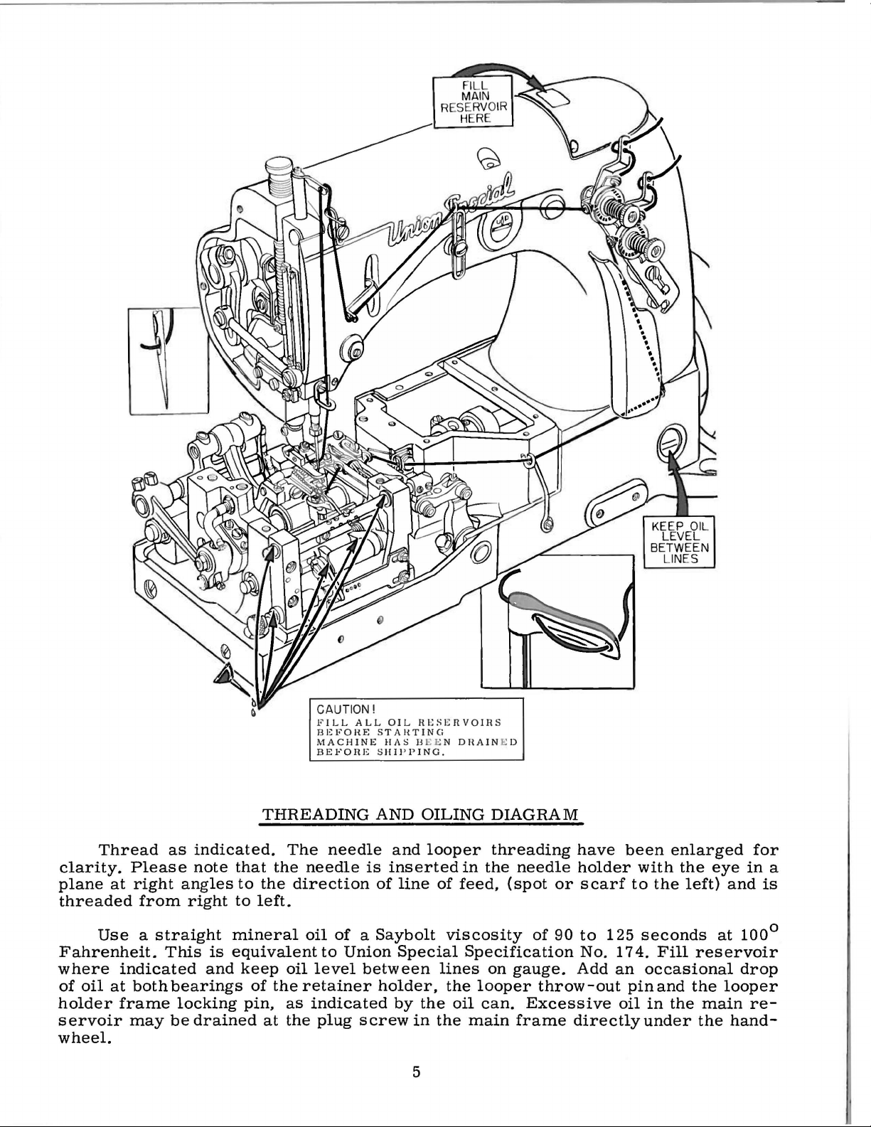
AND
THREADING
machine
Use a straight
Fahrenheit.
top
cover
The
oil
of
the
oil
automatically
bearings
locking
start
is
pin,
should
filtered
unnecessary.
screw
is
inserted
of
the
line
in
manner
of
before
and
level
reservoir
lubricated,
of
the
as
be
made
and
the
main
in
in
the
feed
shipping
mineral
the
oil
should
retainer
indicated
and
pumped
Excessive
frame
which
needle
and
is
and
oil
level
be
is
is
maintained
12
ounces.
and
holder,
in
oil
added
back
directly
these
holder
threaded
the
reservoir
with a Saybolt
checked
between
no
oiling,
the
looper
oiling
oil
if
into
in
diagram,
required.
the
the
under
machines
with
the
eye
from
right
at
the
other
main
main
the
are
in
to
4
Page 5
CAUTION!
FILL
ALL
BEFORE
MACHINE
BEFORE
OIL
RESERVOIRS
STAHTING
HAS BEEN DHAIN
SHII'PING.
E D
Thread
clarity.
plane
Please
at
right
threaded
Use a straight
Fahrenheit.
where
of
holder
servoir
oil
indicated
at
both
frame
may
from
This
as
indicated.
note
angles
right
is
and
bearings
locking
be
drained
THREADING
The
that
the
to
the
direction
to
left.
mineral
equivalent
keep
of
pin,
at
oil
the
as
the
retainer
needle
needle
oil
to
level
indicated
plug
AND
OILING
and
is
inserted
of
line
of a Saybolt
Union
Special
between
holder,
by
the
screw
in
looper
in
of
feed,
viscosity
Specification
lines
the
looper
oil
the
main
DIAGRAM
threading
the
(spot
on
gauge.
can.
wheel.
5
needle
or
of
90
throw
Excessive
frame
have
holder
scarf
to
125
No.
174.
Add
an
-out
oil
directly
been
enlarged
with
to
the
seconds
Fill
occasional
pin
and
in
the
under
the
eye
left)
at
reservoir
the
main
the
for
in
and
is
100°
drop
looper
re-
hand-
a
Page 6
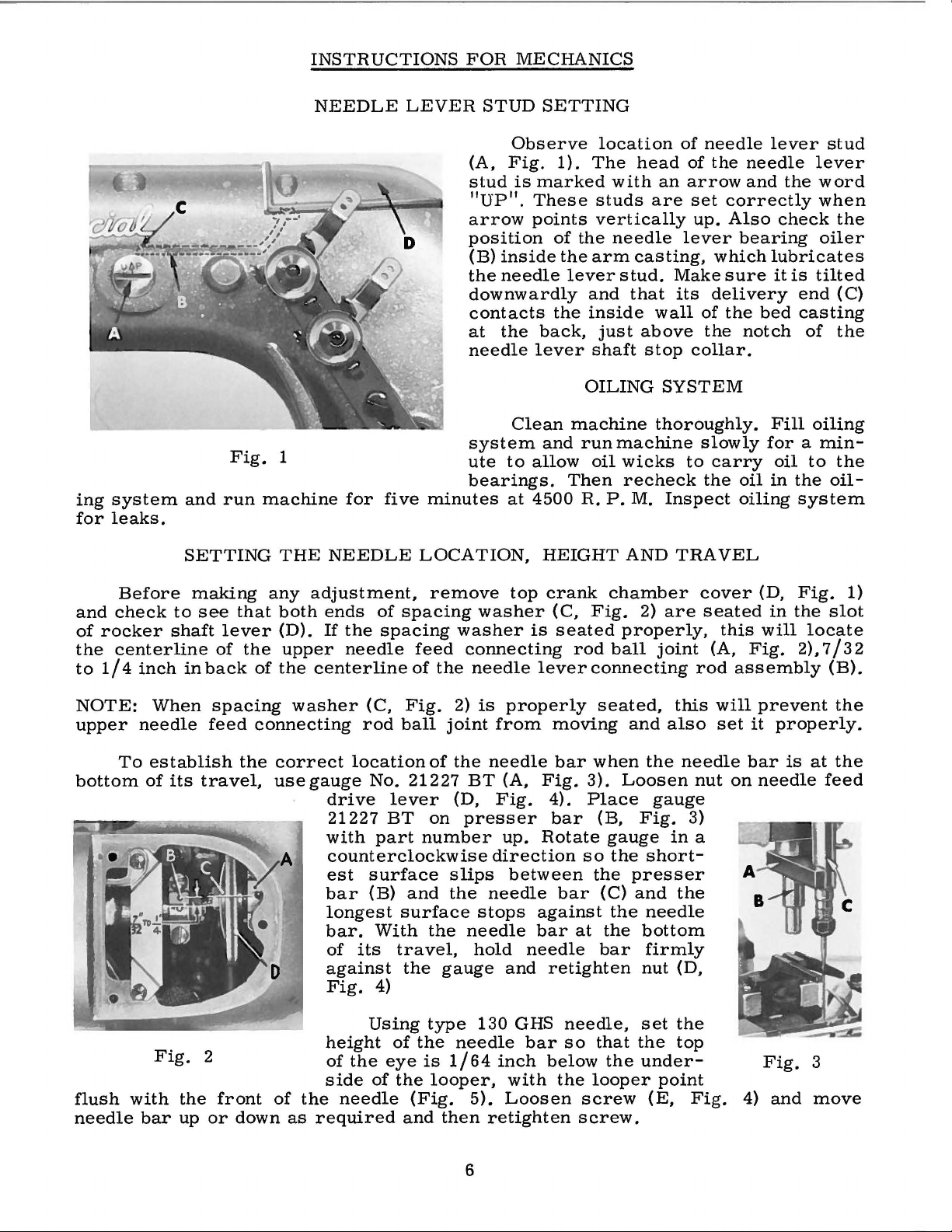
INSTRUCTIONS
FOR
MECHANICS
ing
for
system
leaks.
Fig.
and
run
SETTING
NEEDLE
1
machine
THE
five
for
NEEDLE
LEVER
minutes
LOCATION,
STUD
(A,
stud
"UP".
arrow
position
(B)
the
downwardly
contacts
at
needle
system
ute
bearings.
SETTING
Observe
Fig.
is
marked
These
points
inside
needle
the
back,
lever
Clean
and
to
allow
at
4500
HEIGHT
location
1).
The
with
studs
vertically
of
the
needle
the
arm
lever
and
the
inside
just
shaft
OILING
machine
runmachine
oil
Then
R.
P.M.
head
an
are
casting,
stud.
that
wall
above
stop
SYSTEM
thoroughly.
wicks
recheck
Inspect
AND
of
needle
of
the
arrow
set
correctly
up.
Also
lever
Make
its
collar.
to
TRAVEL
bearing
which
sure
delivery
of
the
the
slowly
carry
the
oil
oiling
lever
needle
and
the
check
lubricates
it
is
end
bed
casting
notch
Fill
for a min-
oil
in
the
system
stud
lever
word
when
the
oiler
tilted
(C)
of
the
oiling
to
the
oil-
Before
and
check
of
rocker
the
centerline
to
1/4
NOTE:
upper
To
bottom
flush
needle
to
shaft
inch
When
needle
establish
of
its
Fig.
with
bar
making
see
of
in
back
spacing
feed
travel,
2
the
front
up
or
any
that
lever
the
of
connecting
the
down
adjustment,
both
(D).
upper
the
centerline
washer
correct
use
gauge
of
the
as
required
remove
ends
If
drive
21227
with
counterclockwise
est
bar
longest
bar.
of
against
Fig.
height
of
side
of
the
spacing
needle
(C,
rod
location
No.
part
surface
(B)
With
its
4)
Using
the
eye
of
needle
spacing
feed
of
Fig.
ball
21227
lever
BT
number
and
surface
travel,
the
type
of
the
is
the
(Fig.
and
the
2)
joint
of
the
(D,
on
slips
the
the
gauge
needle
1/64
looper,
then
top
washer
washer
connecting
needle
is
properly
from
needle
BT
(A,
Fig.
presser
up.
direction
between
needle
stops
needle
hold
130
5).
needle
and
GHS
bar
inch
with
Loosen
retighten
crank
(C,
is
seated
rod
lever
moving
bar
Fig.
4).
bar
Rotate
bar
against
bar
at
retighten
needle,
so
below
the
screw.
chamber
Fig.
connecting
when
3).
Place
so
the
looper
screw
2)
properly,
ball
seated,
and
Loosen
(B,
Fig.
gauge
the
presser
(C)
and
the
the
bottom
bar
nut
set
that
the
the
under-
the
gauge
short-
needle
firmly
(E,
are
joint
this
also
needle
3)
in
the
(D,
the
top
point
Fig.
cover
seated
this
(A,
rod
will
set
nut
a
(D,
in
will
Fig.
assembly
prevent
it
properly.
bar
is
on
needle
Fig.
4)
and
Fig.
the
locate
2),
7/32
at
feed
3
move
1)
slot
(B).
the
the
6
Page 7
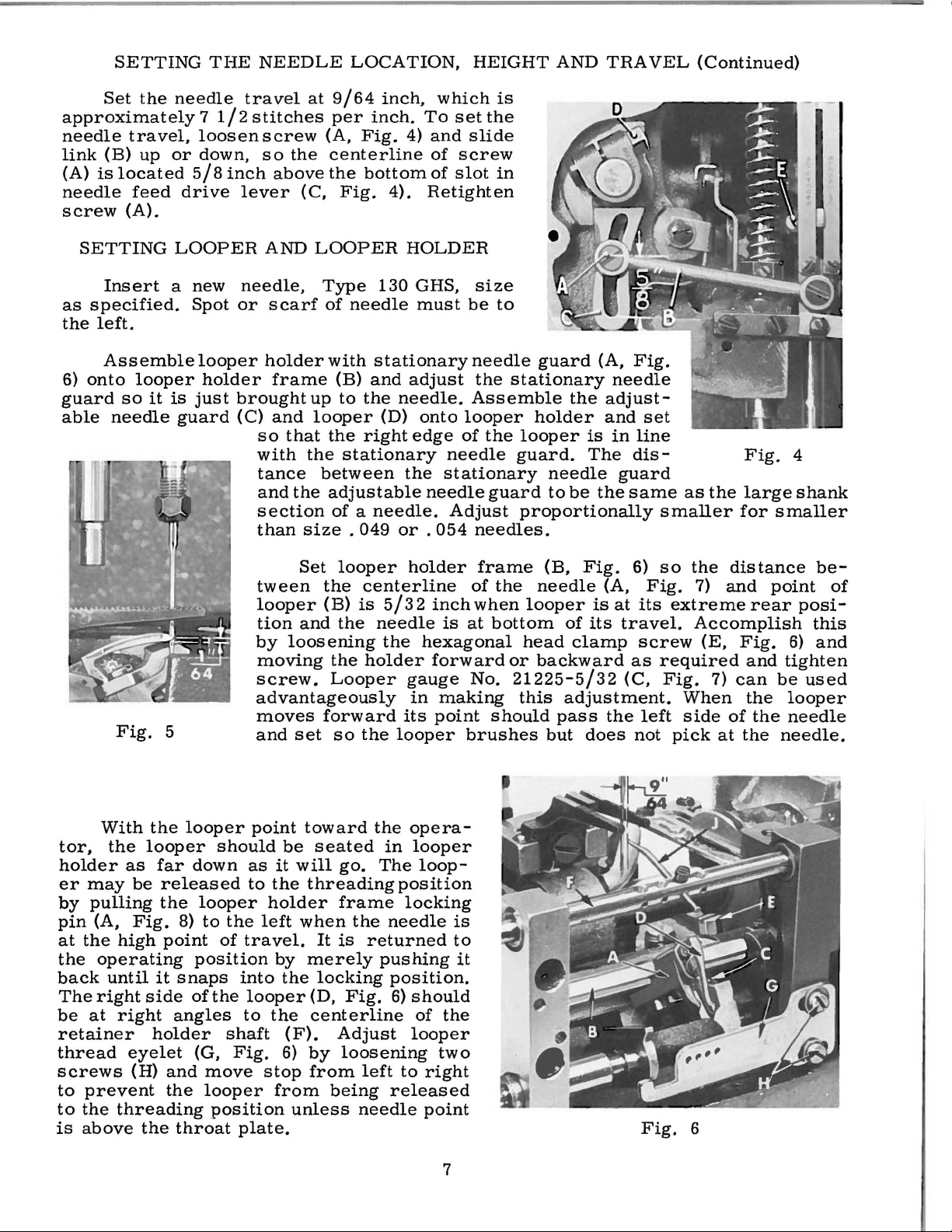
SETTING
Set
the
approximately
needle
link
(A)
needle
screw
travel,
(B)
is
located
(A).
up
feed
or
THE
needle
7
1/2
loosenscrew
down,
5/8
inch
drive
lever
NEEDLE
travel
stitches
so
the
above
at
9/64
per
(A,
centerline
the
(C,
Fig.
LOCATION,
inch,
inch.
Fig.
bottom
4).
which
To
4)
and
of
of
Retighten
HEIGHT
is
set
the
slide
screw
slot
in
AND
TRAVEL
(Continued)
SETTING
Insert
as
specified.
the
left.
Assemble
6)
onto
guard
able
needle
Fig.
looper
so
it
LOOPER
a new
Spot
looper
holder
is
just
guard
5
AND
needle,
or
scarf
holder
brought
(C)
so
with
tance
and
section
than
tween
looper
tion
by
moving
screw.
advantageously
moves
and
LOOPER
Type
of
with
frame
up
and
looper
that
the
between
the
adjustable
size . 049
Set
the
(B)
and
loosening
forward
set
the
of a needle.
the
Looper
so
130
needle
stationary
(B)
and
to
the
needle.
(D)
right
stationary
or . 054
looper
centerline
is
5/32
the
needle
the
holder
its
the
looper
HOLDER
GHS,
must
adjust
onto
edge
the
needle
holder
hexagonal
gauge
in
size
be
needle
the
Assemble
looper
of
needle
stationary
Adjust
needles.
frame
of
inch
when
is
at
forward
No.
making
point
brushes
to
guard
stationary
holder
the
looper
guard.
needle
guard
the
bottom
should
to
proportionally
(B,
needle
looper
head
or
backward
21225-5/32
this
pass
but
(A,
Fig.
needle
the
adjust-
and
set
is
in
line
The
dis-
guard
be
the
same
Fig.
of
clamp
adjustment.
does
is
its
(A,
at
travel.
as
(C,
the
6)
Fig.
its
screw
left
not
as
the
smaller
so
the
7)
extreme
Accomplish
(E,
required
Fig.
When
side
pick
7)
at
Fig.
large
for
smaller
distance
and
point
rear
Fig.
and
can
be
the
of
the
the
needle.
4
shank
be-
of
posi-
this
6)
and
tighten
used
looper
needle
With
tor,
holder
er
may
by
pulling
pin
(A,
at
the
the
operating
back
The
right
be
at
retainer
thread
screws
to
prevent
to
the
is
above
the
the
looper
as
far
be
released
the
Fig.
high
point
until
it
side
right
holder
eyelet
(H)
the
threading
the
looper
down
looper
8)
to
position
snaps
of
angles
(G,
and
move
looper
throat
point
should
as
to
holder
the
left
of
travel.
into
the
looper
to
shaft
Fig.
stop
position
plate.
be
it
will
the
by
the
the
(F).
6)
from
unless
when
toward
seated
go.
threading
frame
the
It
is
returned
merely
locking
(D,
Fig.
centerline
Adjust
by
loosening
from
left
being
needle
the
opera-
in
looper
The
loop-
position
locking
needle
pushing
position.
6)
should
of
looper
to
right
released
point
is
to
it
the
two
7
Fig.
6
Page 8
The
under
Looper
Fig.
Holder".
mechanical
"Setting
Holder",
7
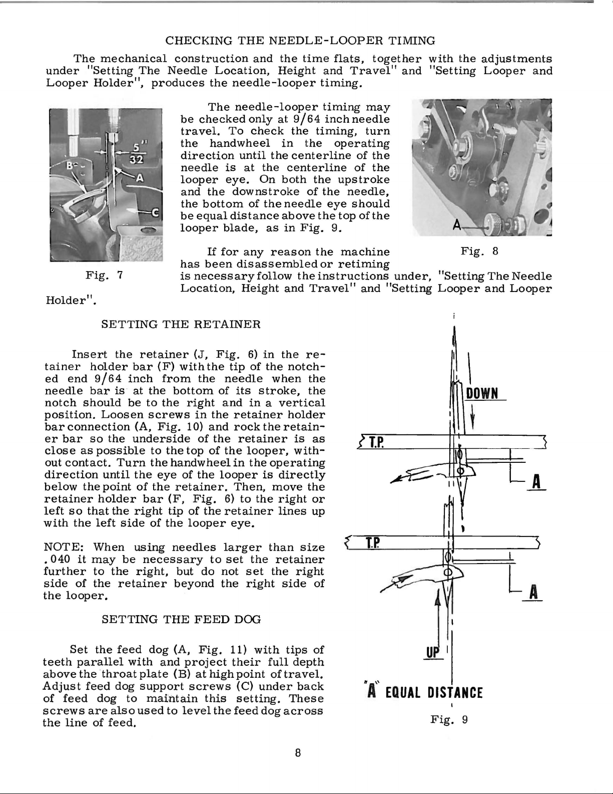
CHECKING
The
Needle
produces
construction
Location,
the
needle-looper
The
be
checked
travel.
the
direction
needle
looper
and
the
be
equal
looper
has
is
necessary
Location,
To
handwheel
is
eye.
the
downstroke
bottom
distance
blade,
If
for
been
THE
needle-looper
disassembled
and
only
check
until
at
the
On
of
the
as
any
follow
Height
NEEDLE-
the
Height
at
9/64
the
in
the
centerline
centerline
both
needle
above
in
Fig.
reason
the
and
LOOPER
time
flats,
and
timing.
timing
inch
timing,
the
operating
the
upstroke
of
the
eye
the
top
9.
the
machine
or
retiming
instructions
Travel"
together
Travel"
may
needle
turn
of
the
of
the
needle,
should
of
the
and
TIMING
and
under,
"Setting
with
the
"Setting
Fig.
"Setting
Looper
adjustments
Looper
8
The
and
and
Needle
Looper
Insert
tainer
ed
end
needle
notch
position.
bar
er
close
out
direction
below
retainer
left
with
NOTE:
.
040
further
side
the
should
connection
bar
as
contact.
the
so
the
it
of
looper.
SETTING
the
holder
9/64
bar
is
Loosen
so
the
possible
Turn
until
point
holder
that
the
left
side
When
may
to
the
the
retainer
retainer
bar
(F)
inch
at
the
be
to
screws
(A,
Fig.
underside
to
the
the
eye
of
the
bar
right
of
using
be
necessary
right,
THE
from
the
RETAINER
(J,
with
the
bottom
right
in
10)
of
the
top
handwheel
of
the
retainer.
(F,
Fig.
tip
of
the
the
looper
needles
but
do
beyond
Fig.
the
of
and
the
and
the
of
looper
retainer
larger
to
not
the
6)
in
tip
of
the
needle
its
stroke,
in a vertical
retainer
rock
the
retainer
the
looper,
in
the
is
Then,
6)
to
the
eye.
set
the
set
right
the
re-
notch-
when
operating
directly
move
right
lines
than
retainer
the
holder
retain-
is
with-
the
size
right
side
the
the
as
or
up
of
~
I
DOWN
t
Set
teeth
above
Adjust
of
feed
screws
the
line
SETTING
the
parallel
the
throat
feed
dog
are
also
of
feed.
feed
with
dog
to
THE
dog
and
plate
support
maintain
used
to
FEED
(A,
project
(B)
screws
level
Fig.
at
high
this
the
DOG
11)
with
their
point
(C)
setting.
feed
full
of
under
dog
across
tips
of
depth
travel.
back
These
8
.A,,
EQUAL
DISTANCE
Fig.
9
Page 9
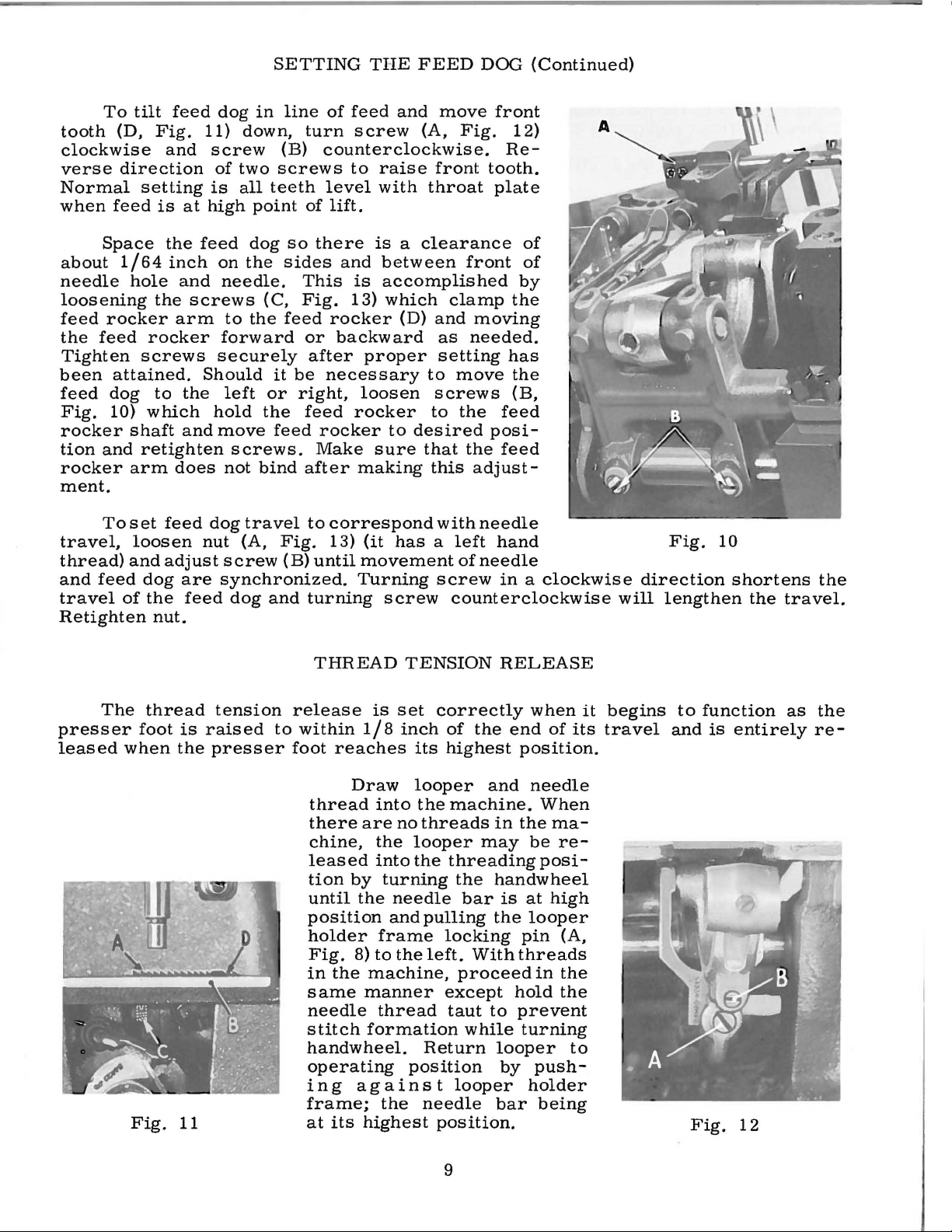
To
tooth
(D,
clockwise
verse
direction
Normal
when
feed
tilt
feed
Fig.
and
setting
is
at
dog
11)
screw
of
two
is
all
high
SETTING
in
line
down,
(B)
screws
teeth
point
of
turn
THE
feed
screw
FEED
and
(A,
counterclockwise.
to
raise
of
level
lift.
with
move
Fig.
front
throat
DOO
front
12)
Re-
tooth.
plate
(Continued)
Space
about
1/64
needle
loosening
feed
rocker
the
feed
Tighten
been
feed
Fig.
attained.
dog
10)
rocker
tion
and
rocker
ment.
To
travel,
thread)
and
feed
travel
of
Retighten
the
inch
hole
and
the
arm
rocker
screws
to
the
which
shaft
and
retighten
arm
does
set
feed
loosen
and
adjust
dog
are
the
feed
nut.
feed
on
dog
the
needle.
screws
to
(C,
the
forward
securely
Should
left
hold
the
move
screws.
not
bind
dog
travel
nut
(A,
screw
synchronized.
dog
so
sides
feed
it
or
feed
Fig.
(B)
and
there
and
This
Fig.
rocker
or
backward
after
be
necessary
right,
feed
rocker
Make
after
to
correspond
13)
until
turning
THREAD
is a clearance
between
is
accomplished
13)
which
(D)
and
as
proper
setting
to
loosen
rocker
sure
making
to
desired
screws
to
that
this
with
(it
has a left
movement
Turning
screw
screw
TENSION
of
front
of
by
clamp
the
moving
needed.
has
move
the
(B,
the
feed
posi-
the
feed
adjust-
needle
hand
of
needle
in a clockwise
counterclockwise
RELEASE
direction
will
Fig.
10
lengthen
shortens
the
travel.
the
The
presser
leased
thread
foot
when
Fig.
is
the
11
tension
raised
presser
release
to
within
foot
thread
there
chine,
leased
tion
until
position
holder
Fig.
in
same
needle
stitch
handwheel.
operating
in
frame;
at
is
1/8
reaches
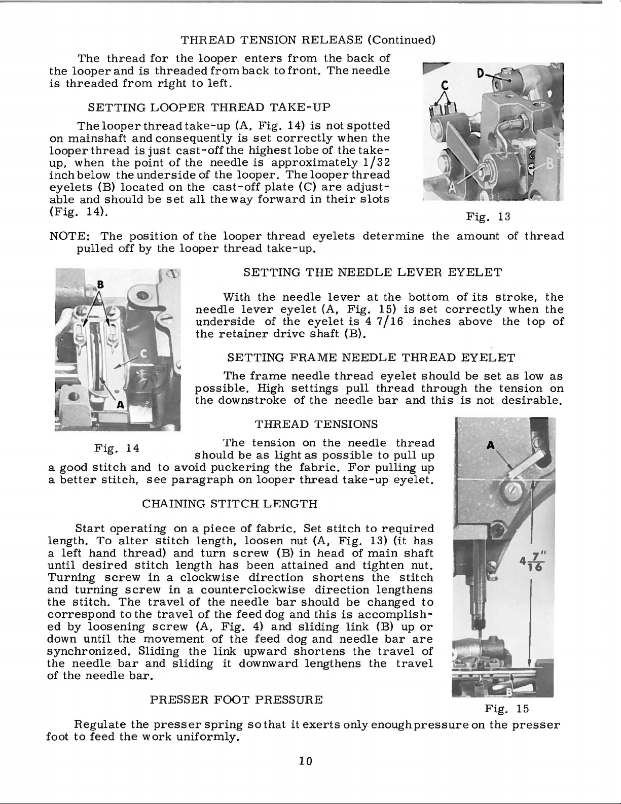
Draw
into
are
the
into
by
turning
the
frame
8)
to
the
machine,
manner
thread
formation
g a g a
the
its
highest
set
correctly
inch
of
the
its
highest
looper
the
machine.
no
threads
looper
the
may
threading
the
needle
and
bar
pulling
locking
the
left.
With
proceed
except
taut
while
Return
position
ins t looper
needle
position.
when
end
of
position.
and
needle
When
in
the
rna-
be
re-
posi-
handwheel
is
at
high
the
looper
pin
(A,
threads
in
the
hold
the
to
prevent
turning
looper
by
push-
holder
bar
being
its
to
it
travel
begins
to
and
Fig.
function
is
entirely
12
as
the
re-
9
Page 10
the
looper
is
threaded
The
thread
and
from
for
is
threaded
right
THREAD
the
looper
from
to
left.
TENSION
enters
back
to
from
front.
RELEASE
the
back
The
needle
(Continued)
of
The
on
mainshaft
looper
up,
when
inch
below
eyelets
able
(Fig.
NOTE:
pulled
SETTING
looper
thread
the
the
(B)
located
and
should
14).
The
off
LOOPER
thread
and
consequently
is
just
point
underside
be
set
position
by
the
take-up
cast-off
of
the
on
the
all
of
looper
needle
underside
the
possible.
the
THREAD
the
needle
of
the
cast-off
the
way
the
looper
thread
With
retainer
SETTING
The
downstroke
TAKE-
(A,
Fig.
is
set
highest
is
approximately
looper.
plate
forward
thread
take-up.
SETTING
the
lever
of
drive
frame
High
UP
14)
is
correctly
lobe
The
looper
(C)
in
eyelets
THE
needle
eyelet
the
eyelet
shaft
FRAME
needle
settings
of
the
not
spotted
when
of
the
are
adjust-
their
NEEDLE
lever
(A,
Fig.
(B).
NEEDLE
thread
pull
needle
the
take-
1/32
thread
slots
determine
at
the
15)
is 4 7/16
eyelet
thread
bar
the
LEVER
bottom
is
set
inches
THREAD
should
through
and
this
Fig.
amount
EYELET
of
its
correctly
above
EYELET
be
set
the
is
not
13
of
thread
stroke,
when
the
top
as
low
tension
desirable.
the
the
of
as
on
Fig.
a
good
a
better
length.
a
left
until
Turning
and
the
correspond
ed
down
synchronized.
the
of
foot
stitch
stitch,
Start
turning
stitch.
by
needle. bar
the
Regulate
to
operating
To
hand
desired
screw
loosening
until
needle
feed
14
and
see
CHAINING
alter
thread)
stitch
in a clockwise
screw
The
travel
to
the
the
movement
Sliding
and
bar.
PRESSER
the
the
work
The
tension
should
to
avoid
paragraph
on a piece
stitch
travel
screw
presser
length,
and
turn
length
in a counterclockwise
of
of
(A,
the
sliding
spring
uniformly.
be
puckering
on
STITCH
of
loosen
screw
has
been
direction
the
needle
the
feed
Fig.
of
the
link
it
downward
FOOT
upward
so
4)
THREAD
on
as
light
looper
LENGTH
fabric.
dog
and
feed
PRESSURE
that
the
fabric.
thread
Set
nut
(B)
in
attained
bar
should
and
sliding
dog
shortens
it
exerts
as
lengthens
TENSIONS
the
needle
possible
For
take-up
stitch
(A,
head
shortens
direction
this
and
to
Fig.
of
and
tighten
be
is
accomplish-
link
needle
the
only
thread
to
pull
pulling
eyelet.
required
13)
(it
main
the
changed
the
enough
shaft
stitch
lengthens
(B)
up
bar
travel
travel
up
up
has
nut.
to
or
are
of
pressure
on
Fig.
the
15
presser
10
Page 11

IDENTIFYING
PARTS
Where
some
identification
appear.
OF
ILLUSTRATIONS
of
actual
listing
required
of
Part
IMPORTANT!
MACHINE
This
various
the
the
smaller
numbers
catalog
sections
position
of
the
in
the
construction
letter
FOR WI-
in
parts
parts
is
stamped
represent
ON
ITCH
has
been
of
the
the
machine.
with
particular
permits,
and
the
ALL
ORDERS,
PART
ORDERING
arranged
mechanism
their
part
view
on
those
in
to
same
IS
On
numbers,
being
each
distinguish
ORDERED.
to
are
the
shown.
part
where
part,
PLEASE
REPAIR
simplify
shown
page
is
stamped
the
construction
the
part
regardless
INCLUDE
PARTS
ordering
so
that
opposite
descriptions
from
PART
repair
the
parts
the
illustration
with
of
and
its
does
similar
catalog
NAME
parts.
may
the
number
part
number.
not
permit,
ones.
in
which
AND
Exploded
be
seen
will
in
be
of
On
an
they
STYLE
views
their
found
pieces
a
Numbers
position
ordering
indicated
assembly.
46
47
48
49
are
recommended,
catalog,
parts
in
the
of
parts.
Component
by
29105
22559
22894
22559
It
will
be
not
listed.
In
those
no
for
the
description,
in
the
the
part
Always
parts
indenting
Example:
AD
B
c
A
noted
The
so
the
cases
specific
various
first
in
in
reason
where a part
usage
and
column
the
illustration.
use
the
of
sub-assemblies,
their
Retainer
Bearing
Set
Bearing
the
above
is
complete
will
machines
if
necessary,
are
reference
Reference
part
number
descriptions
Drive
Screw----------------------------------------
that
sub-assembly
be
are
Eccentric
Screw,
Screw,
example,
replacement
is
common
mentioned
not
the
the
difference
same,
numbers
numbers
listed
which
under
upper----------------------------lower-----------------------------
that
can
the
Assembly---------------------
the
of
these
should
to
all
in
the
the
will
only
should
in
the
second
be
furnished
description
eccentric,
parts,
be
ordered.
of
the
machines
description,
specific
be
usage
shown
and
merely
never
column.
for
of
the
ball
stud
individually,
covered
however,
will
be
in
the
indicate
be
used
repairs
main
and
when
mentioned
illustration.
are
sub-
bearing
is
not
by
this
the
the
in
1
2
5
2
At
the
this
part
book.
number
back
This
is
known.
of
will
the
book
facilitate
will
locating
be
found a numerical
the
illustration
11
index
and
description
of
all
the
parts
when
shown
only
in
the
Page 12

12
Page 13

I~
c
r.
N
o.
~
;)
'I
5
6
7
u
9
10
11
12
Li
14
15
16
17
18
19
20
21
22
2:)
24
25
26
27
2B
29
30
31
32
33
34
35
:)6
:n
38
39
40
41
42
43
44
45
46
47
48
49
50
51
52
53
54
55
56
57
58
59
60
61
62 95
63
64
65
66
67
68
69
70
1-'nrt
No.
54601
22H:W
54681
5
4681
:
1577~
n560
22845
80
22574
22562
22562
22U39
54680
22U48
22n:)
41:)94
22585
22524
22541
53782
52882
39582
52882
50-789
52882
90
51382
22548
52882
52882
51282
52882
90
52882
93
B21375
98
52 A
51291
52958
54282
20
22848
294
22572
54682
54682
54682
52882
52882
35731
2
251:1
22569
12934
54682
54637
22528
54658
98
22517
53137
22848
20
539
22889
22784
22891 A
54670
719
c
A
II
A
Fl
A
1:1
A
A
13
B
AD
L
AC
AA
A
AE
u
AE
p
y
AI-I
A
A
B
A
B
A
L
iVI
A
c
A
c
B
c
A
A
F
A
A
F
Blk.
!\'lAIN
FHA
ME,
MISCELLANEOUS
Cloth
Plate----------------------------------------------------------
Screw,
Cloth
Screw,
Screw,
Throat
Screw,
Screw,
Screw,
Throat
Screw,
Plug
Gasket,
Screw,
Screw,
Screw,
Oil
Crank
Gasket,
Screw,
Crank
Gasket,
Needle
Gasket,
Screw,
Baffle
Screw,
Belt
Screw,
Looper
Looper
Frame
Oil
Washer,
Screw,
Screw,
Screw,
Head
Head
Oil
Gasket,
Presser
Screw,
Screw,
Nut,
Needle
Guide
Needle
Needle
Screw,
Screw,
Pin,
Plug
Screw,
Washer,
Frame
Adaptor
Screw,
Screw,
Needle
Screw,
for
cloth
Plate
Spring
\Vasher
Screw-----------------------------------------------------------
Screw-----------------------------------------------------------
for
for
Plate
for
for
for
Plate
for
Screw----------------------------------------------------------
for
for
for
for
.Reservoir
Chamber
Oil
Cap
Oil
Cap
Oil
Cap
Oil
Drip
Screw-----------------------------------------------------------
for
lower
Chamber
for
Lever
for
for
Plate
for
Guard
for
Thread
Thread
Looper
Shield
.Reservoir
-----------------------------------------------------------
for
for
for
for
Cover
Felt
Liner
Cover
for
Bar
for
guide
for
stud
Bar
Stud
Bar
Thread
for
for
for
needle
Screw,
for
for
Needle
Screw,
for
for
Thread
for
plate------------------------------------------------
Cover
----------------------------------------------------------
cloth
cloth
throat
throat
throat
oil
oil
oil
upper
baffle
belt
----------------------------------------------------------
thread
oil
head
head
presser
Frame
Support
Frame
lower
needle
frame
needle
needle
needle
Assembly-------------------------------------------
---------------------------------------------------------
plate-----------------------------------------------plate------------------------------------------------
(See
Page
25)
plate,
plate,
plate
Support-------------------------------------------------
reservoir
plug
screw
reservoir
reservoir
crank
Top
Cover,
--------------------------------------------------------Torsion
Hinge
Plate---------------------------------------------------
oil
reservoir
crank
Cover,
lower
Bearing
upper
plate
--------------------------------------------------------guard-------------------------------------------------
Eyelet
Guard
Thread
oil
shield------------------------------------------------
shield-------------------------------------------------
cover------------------------------------------------
cover
---------------------------------------------------------
------------------------------------------------------
Gasket---------------------------------------------------
Back
oil
reservoir
Connection
stud
No.
22528
Eyelet,
needle
bar
for
bed--------------------------------------------------
needle
frame
Thread
for
Take-up
lever
Styles
Style
support----------------------------------------
back
----------------------------------------------top
top
chamber
Cover
Pin------------------------------------------------
crank
crank
eyelet
support---------------------------------------------
Guard
---------------------------------------------------
Guide
bar
thread
bar
---------------------------------------------
upper-----------------------------------------
Spring-------------------------------------------
top
chamber
lower-----------------------------------------
chamber
Oiler-------------------------------------------
chamber
-----------------------------------------------
and
------------------------------------------------
-----------------------------------------------Eyelet------------------------------------------
-----------------------------------------------
Cover
back
Guide
bar
connection
C---------------------------------------------
---------------------------------------------
Stud
lower------------------------------------------
thread
frame
frame
thread
needle
Eyelet------------------------------------------
frame
take-up
frame
Wire------------------------------------------
stud
COVEHS
Description
-------------------------------------------54600
54600
cover
cover------------------------------------cover-------------------------------------
cover-----------------------------------cover------------------------------------
looper
--------------------------------------------
-----------------------------------------
pin---------------------------------------
--------------------------------------------
thread
needle
pivot
------------------------------------------
AB,
AA
-----------------------------------
cover---------------------------------
cover-------------------------------cover--------------------------------
thread
cover----------------------------------Plate-----------------------------------
guide
eyelet----------------------------------
eyelet----------------------------------
eyelet
thread
wire----------------------------------
pin----------------------------------
AND
PLATES
AD---------------------------
--------------------------------
guard------------------------
plate---------------------------
-------------------------------eyelet--------------------------
A
mt.
Heq.
1
2
1
1
3
3
1
3
1
1
4
4
:)
1
9
1
2
2
7
3
1
1
1
1
1
1
2
1
4
1
1
1
1
2
1
2
1
3
1
1
1
1
3
3
2
1
1
1
1
1
1
2
4
2
1
1
1
1
1
1
1
1
1
1
1
1
1
1
1
1
2
13
Page 14

A B
c
D
F G
~
~~
54
55
_;or
56
58
~51
~55
€il55
59
lso
~55
160
.
s2 sJ
61
1
~
14
Page 15

Bel'.
Nu.
1
2
:~
4
5
6
7
8
!)
10
11
12
1:3
14
15
16
17
18
19
20
21
22
23
24
25
26
27
28
29
30
31
32
33
34
35
36
37
38
39
40
41
42
43
44
45
46
47
48
49
50
51
52
53
54
55
56
57
58
59
60
61
62
63
I-'
art
N
o.
5149:~
BQ
5~H
643-127
5149:~
AG
5149:3 D
5149:3 E
51493
Ail
50-294
22569
5149:3
51493
22645
51493
B
1311
B.J
H-64
BG
2282:3 A
51295
22823
5149:3
52944
5149:3
51242
51242
A
B
AY
T
BK
z
H
52936
52890
51290
51242
22571
54293
c
T
s
B
A
90
52894
AB
51257
AA
660-136
258
A
666-217
54694
666-218
22569
c
20
54694
A
666-99
22706
51294
A
N
21212
52883
H
666-201
666-209
22729
51294
22729
51294
21657
52891
A
u
B
K
X
B
50-648
56:390 E
225:39
22571
H
A
666-111
666-179
666-118
666-65
35178
D
666-114
22889
22889
D
c
MAIN
Blk.
FHk.
Blk.
FHAME,
Oil
Gasket,
Oil
Oil
Oil
Oil
Screw,
ilter
F
Screw, oil
Base
Screw,
ounting
M
Screw,
Oil
Looper
Lint
Looper
Looper
Feed
middle
Main
upper
!\lain
Looper
Plug
Feed
Screw,
Oil
Presser
Oil
Head
Horizontal
Screw,
Washer,
Oil
Oil
Wick,
Plug
Oil
Presser
Felt
Felt
Screw,
Oil
Siphon
Tension
Crankshaft
Lucile
Crankshaft
Plug
Plug
Oil Wick,
Wedge
Oil Wick,
Oil
Wick,
Spring,
Oil
Wick,
Adaptor
Adaptor
BUSIJINGS
AND
MISCELLANEOUS
OILING
PAWl'S
Description
Pump
Pump
Pump
Driving Shaft
Pump
Driven
Screw -----------------------------------------------------
for
oil
Gear---
pump
---
-------------------------------------
housing------------------------------------1-Iousing----------------------------------------------Driving
Housing
Pin
-------------------------------------------------------
for
oil
Cap
Assembly--------------------------------------------
\Vasher,
pan
Plate
Felt:-------------------------------------------------
oil
pan
Shaft------------------------------------------
Gear-------
Cover
pump
housing
-
-----------------------------------
---------------------------------------cover
-------------------------------
rubber--------------------------------------------
assembly
assembly
----------------------------------------
----------------------------------------
Isolator-----------------------------------------------
oil
pan
Pan Assembly----
Hocker
Filter
Drive
Drive
Hocker
and
Shaft
left
Shaft
Drive
Screw,
Lift
for
Tube
Bar
Tube,
assembly-----------------------------------------
-
------------------------------------------
Shaft
Bushing,
left--------------------------------
Screen----------------------------------------------
Lever
Lever
Shaft
right
Bushing,
and
Bushing,
Lever
for
Eccentric
oil
Holder
Bushing,
for
feed
Shaft
Shaft
Bushing
Bushing,
Bush
and
front--------------------------
ing,
middle
Looper
------------------------
Hocker
---------------------------------------------left,
inner
right
and
Hocker
right--------------------------------------------
middle-------------------------------------Shaft
Bushing,
rear
--------------------------
bed--------------------------------------------
Oil
Tube-------------------------------------
tube----------------------------------------------
-----------------------------------------------lower-------------------------------------
crank
link
assembly
---------------------------
Shaft
Shaft
Nut--------------------------------------------------------
Oil
Attraction
Siphon
Siphon
Tube
Priming
for
oil
for
oil
Clamp-------------------------------------------------
for
upper
Felt
Oil
tube
tube
-----------------------------------------
Tube---------------------------------------
Block, felt
----------------------------------
clamp----------------------------------------
clamp
rocker
--------------------------------------
shaft
bushin
g,
left
---------------------
Screw-----------------------------------------------------
Tube
Connection---------------------------------------------
Locking
Plug
Disc
Sere~
Clamp,
Oil
Screw,
Screw,
Hing
Foot Lif
-----------------------------------------------
ter
Lever
Bushing-------------------------------
------------------------------------------------------
------------------------------------------------------
for oil
Helease
siphon
Assembly
·
----------------------------------------------------upper
Bushing Housing,
Gau
ge
Bearing
for
assembly-----------------------------------
--------------------------------------------
----------------------------------------------
Lever
Bushing ----------------------------------
including bus hi
----------------------------------------------Housing
Gasket-------------------------------
bed---------------------------------------------
for bed---------------------------------------------13
for
feed
rocker
shaft-----------------------------------
ng---------------------
Pin-----------------------------------------------------
for main s
for
looper
for
oil
for main s h
Plug
Screw
Plug
Screw---------------------------------------------
haft
bush
ing
left
and
rocker shaft
bushing
middle
-------------------------
-------------------
wick---------------------------------------------
aft
bush
ing
right
and
inner
right---------------
---------------------------------------------
Bushing,
Bushing,
A
Hc
2
2
4
2
1
2
1
1
1
1
1
1
1
1
1
1
1
1
1
1
1
1
1
1
1
1
1
1
1
1
1
2
2
mt.
q.
1
2
1
1
1
2
1
1
3
1
1
1
1
1
4
1
1
1
1
1
1
4
4
1
1
1
1
1
1
15
Page 16

/
/
/
/
/
/
.,......
I
I
I
I
I
~.-.-----
~~~ /~//1
I
I
I
I
/
16
Page 17

l~ef.
No.
2
:i
4
5
G
7
H
9
10
11
12
l:i
14
15
16
17
l!l
19
20
21
22
2:i
24
25
26
27
28
29
30
31
32
33
34
35
36
37
38
39
40
41
42
43
44
45
46
47
48
49
50
51
52
53
54
55
56
57
58
59
60
61
62
63
64
65
66
67
68
69
70
71
72
Part
No.
56
54617
27- 4!H
56351:!
2276B
CL21
225!!6 B
51250
51250
660- 2
51150
29066
22559
51216N
51216
51216
lB
54652
52952
22559
52916
52951
29126
660-246
52951
52951
546:~8
95
294 76
51216
54647
88 F
52921
22894
G
22569
660-202
52891
B
51236
A
51493
BP
22560
B
29133
N
22894
c
22768
22729
51243
c
29105
AD
22559
B
22!l94 c
22559
A
12982
51242
p
51242
L
52841
G
51242
1\11
52841
J
51242
y
51242
L
A
22883
51242
M
81
22852
A
29348
X
54654
97
H7A
54654
c
28
22839
A
54615
51250
E
54658
22768
F
I)
12
H
G
p
G
B
G
c
Dll
B
A
l\1 z
1\11
B
B
13Lk.
CHANI<SHAFT,
Needle
Needle
Washer,
Needle
Screw
Oil
Plug
Gasket,
Washer,
Oil
Needle
Needle
Washer,
Nut,
Needle
Nut,
Spacer
Needle
Needle
Thrust
Needle
Crankshaft
Counterweight-------------------------------------------------------------
Screw--------------------------------------------------------------------
Pulley--------------------------------------------------------------------
Screw,
Oil
Cr
Link
Oil
Looper
Screw,
Ball
Retainer
Lock
Looper
Thrust
Locking
Washer
Nul,
Looper
Thrust Was
Plug
Washer,
Spot Scr
Clamp
Needle
Needle
Screw,
CLamp
Bar,
for
Bar
for
Wlck,
Seal
Seal
ankshaft
Pump
Screw---------------------------------------------------------------Needle
Needle
for
Sc1·ew,
for
for
Hing,
Lever
Lever
Screw--------------------------
for
for
needle
Lever
for
ball
Washer,
Feed
Screw-----------------------------------
Feed
\Vasher,
Feed
Tru-Arc
Retaining
Connecting
Eccentric, . 100
Screw----------------------------------------------------------------
Needle
Screw----------------------------------------------------------------
Screw---------------------------------------------------------------Screw----------------------------------------------------------------
Screw----------------------------------------------------------------
Bearing
Set
Bearing
Ball
Assembly, . 990
for
crankshaft
Ring,
Bushing
Pin,
for
Driving
Drive
for
ball
Stud
Guide
Drive
Screw-------------------------------------------------------------
Nut,
for
Drive
Washer------------------------------------------------------------
Stud--------------------------------------------------------------
------------------------------------------------------------------
for
locking stud-------------------------------------------------------
Drive
her------------------------------------------------------------
Screw
---------------------------------------------------------------
for
ew,
Screw,
Lever
Joint
Screw-----------------------------------------------------------Screw------------------------------------------------------------
Guide
Screw------------------------------------------------------------
Lever,
Lever
Lever
for
needle
NEEDLE
Nut---------------------------------------------------------
marked
needle
Eyelet------------------------
needle
ball
for
needle
needle
Stop
Connecting
needle
Connecting
joint
Connecting
Drive
Drive
Ring---------------------------------------------------------
Washer------------------------------------------------------
Bearing--------------------------------------------------------28
looper
Eccentric
Screw,
Screw,
screw
Lever
Lever
looper dri
for
for
Assembly----------------------------------------------------
Assembly---------------------------------------------------
Washer-----------------------------------------------------
Thread
"EE"
bar
bar
joint
needle
lever
lever
for
needle
Collar
lever
lever----------------
assembly------------
for
ball
Connecting
for
crankshafi
Eccentric
Hod
Bearing------------------------------------------------
inch
for
pulley---------------------------------------------------
Housing,
drive
Gear
stud
guide
Fork-------------------------------------------------------
Eccentric
upper--------------------------------------------------
lower--------------------------------------------------
No.
Shaft
Hocker------------------------------------------------
looper
looper dri
including bushing----------------------------------------
Stud----------------------------------------------------lever
LEVER
-------------------------------------------------
eyelet----------------------------------------------
eyelet------------
'assembly
lever
stud-------------
stud--------------
lever
-----------------------------
Hod
-----------------------
Hod-------------
joint
Rod
Ball
throw---------------------------------------------
inch
bushing
eccentric
---------------------------------------------------Assembly, . 312
fork----------------------------------------------
Assembly-----------------------------------------
81-------------------------------------------------
--------------------------------------------------
ve
lever
drive
lever rocker------------------------------------
ve
Eyelet------------------------------------------------
thread
AND
LOOPEH
Description
- -
-------
stud-------
stud------
Assembly---
assembly--------
Joint,
Rod------------------------------------------
---------------------------------------------
Assembly--------------------------------------
throw---------------------------------------
housing---------------------------------------
including
assembly--------------------------------
rocker---------------------------------------
lever
rocker----------------------------------
eyelet----------------------------------------
----------
--
------ - -
--
-------
---
- - - -
--
-
-------------------------------------
- -
--------------
--
-
-----
upper------
bushing-------------------------------
inch
DRIVING
- ------------
-------------
--
----------------
-
---
--------
---
- -
-- --
----------
-
--------------------------
------
--
- - -
---------
-
-----------------------------
-
-
----------------------------
throw---------------------------
PARTS
-
--------------
------------------------
---------
- -
---
- - - - -
-
--------------------
---
- -------------------
----
------------------------
----------
-------------
--
- -
------
--
-------------
------------------
--------
-----
---
- -
--------
------------------
- - -
------------
--
------
- -
----
---
A
mi.
Hcq.
1
1
1
1
1
1
1
1
1
2
1
1
2
2
1
1
1
2
2
1
1
1
1
1
1
2
1
2
1
2
3
1
1
1
1
2
1
2
1
1
1
1
2
5
2
1
1
1
1
1
1
1
1
1
1
1
1
1
1
1
4
1
1
1
1
1
1
1
17
Page 18

18
Page 19

NEEDLE
FEED
PARTS,
CAST-OFF
PLATE,
NEEDLE
BAR
AND
NEEDLE
HEAD
Ref.
No.
1
2
3
4
5
6
7
8
9
10
11
12
13
14
15
16
17
18
19
20
21
22
23
24
25
26
27
28
29
30
31
32
33
34
35
36
Part
No.
52849
51147
95
52951
54637
55235
6042
55235
51771
22758
54637
43139
61985
54654
22593
54637
61341
52849
22539
52952
55235
6042
55235
54617
22528
21657 E
54657
54604
52958
52904
c
D
E
A
D
H
c
A
A
D
F
c
95
660-202
D
c
D
A
E
56
50-216
28
A
73
D
G
Blk.
Description
Needle
Rocker
Thrust
Needle
Ferrule,
Screw,
Link
Nut,
Needle
Ball
Screw,
Needle
Washer,
Rocker
Oil
Plug
Needle
Needle
Needle
Screw,
Washer,
Dowel
Cast-off
Cast-off
Screw,
Screw,
Looper
Cast-off
Feed
Shaft
Screw----------------------------------------
Washer,
Feed
Nut
Washer
Locking
for
---------------------------------------------
for
Bar
Stud
for
Bar
Shaft
Screw----------------------------------------
Seal
Screw,
Feed
Locking
Washer
Nut
Bar,
Clamp
for
Pin,
for
for
Thread
Rocker
Collar
Drive
------------------------------------------
--------------------------------------
Stud----------------------------------
for
link----------------------------------
link
link--------------------------------------
Frame
Guide-----------------------------------
ball
Frame---------------------------------
for
needle
Oil
Ring,
------------------------------------------
for
Support
Plate-------------------------------------
Wire-------------------------------------
for
for
Rocker
Stud----------------------------------
-------------------------------------marked
Nut---------------------------------
cast-off
cast-off
for
cast-off
cast-off
eyelet
Take-up
Shaft
-------------------------------
for
needle
Lever,
-----------------------------------
Pivot
stud
guide--------------------------
bar
Seal
rocker
bed-------------------------------
Shaft
"EE"--------------------------
support
support
Plate
plate---------------------------
and
--------------------------
feed
left----------------------
Pin------------------------
frame
Collar------------------------
shaft----------------------
Lever,
plate
support
-----------------------------
cast-off
Eyelet
rocker
----------------------
right
-------------------
plate
plate----------------
wire------------------
---------------------
shaft
--------------
------------------
---------
Amt.
Req.
1
1
2
1
1
1
1
1
2
2
1
1
1
2
4
1
1
1
2
1
1
1
1
1
1
1
1
1
1
2
1
1
2
3
2
1
19
Page 20

20
Page 21

Hd.
10
11
12
13
14
15
16
17
18
19
20
21
22
23
24
25
26
27
28
29
30
31
32
33
34
35
36
37
38
39
40
41
42
43
44
45
46
47
48
48
50
51
52
53
54
55
56
57
58
59
60
61
62
63
64
65
66
67
68
69
70
71
72
73
74
No.
1
2
:i
4
5
6
7
8
8
Part
No.
54608
54625
.TB7
,J
22559
I)
54685
54244
lVI
22542
A
54244
I)
51242
L
5421:!5
c
6042
A
54244
H
:39173 A
660-215
22768
54244
13
22519
c
54244
H
54244
E
54244
F
54244
c
51244
K
54644
22884
\V
43245
I)
51244
L
54644
18
20
55244
G
51223
A
22580
D
29476 KH-072
54245
c
51306
22894
D
54622
22768
82
51236
B
51236
G
51236
E
51236
F
51236
D
660-169
20
269
51054
666-149
77
482
98
51235
A
51235
G
22519
c
51235
98
51134
c
51134
p
51134
H
8
54134
N
22560
B
54234
c
HA61 D
77
51236
A
667
B-20
54234
B
22733
22560
B
1:!8
F
531
TAKE-UP,
Looper,
Looper
Screw,
Screw,
Looper
Looper
Screw,
Looper
Thrust
Nut,
Washer,
Throw-out
Looper
Hetaining
Screw,
Looper
Looper
Looper
Looper
Thrust
Screw,
T
T
Looper
Double
Feed
Main
Screw,
Stitch
Feed
Feed
Feed
Washer
Nut,
Feed
Screw-------------------------------------------------------------------Feed
Feed
Feed
Feed
Lubricating
Lubricating
Rocker
Pin,
Screw,
Feed
Feed
Screw,
Screw,
Link
Dowel
Feed
Screw,
Screw,
MAIN
SHAFT,
marked
Holder
for
looper---------------------------------------------------------
for
looper
Holder
Holder
for
locking
Holder
Washer,
for
looper
for
looper
Fork
Holder
Ring------------------------------------------------------------
for
needle
Holder
Screw----------------------------------------------------------------
Holder
Bushing,
Bushing,
Throw-out
Hocker
Collar,
for
hrust
hrust
Nut
Washer
Locking
Screw----------------------------------------------------------------
Eccentric
Eccentric, . 072
Feed
Feed
Needle
Lubricating
Screw---------------------------------------------------------------\Vasher---------------------------------------------------------------
Screw---------------------------------------------------------------Screw----------------------------------------------------------------
Screw---------------------------------------------------------------Screw----------------------------------------------------------------
thrust
Collar,
Washer,
Holder
------------------------------------------------------------------
-------------------------------------------------------------Stud----------------------------------------------------------
Disc
Take-up-------------------------------------------------------
Lift
Eccentric
Screw------------------------------------------------------------
Shaft----------------------------------------------------------------
for
feed
Regulating
Crank
Stud
Crank
Stud-----------------------------------------------------------
Crank
left
Crank
Hocker
Hocker
Rocker--------------------------------------------------------------
Bar
for
Bar
Dog
Pin,
Bar-----------------------------------------------------------------
Link
Crank
Crank
Bearing
-----------------------------------------------------------------thread
Link
Arm---------------------------------------------------------
Shaft------------------------------------------------------------
Felt----------------------------------------------------------Felt
Shaft--------------------------------------------------------------
feed
for
feed
Tilting
(See
for
feed
for
link
for
Pin,
for
for
feed
for
feed
FEED
DHIVING AND
Description
"C\V"----------------------------------------
Needle
and
Frame
Frame
Frame
Frame
Frame
left----------------------------------------------------------
right
Shaft------------------------------------------------------left--------------------------------------------------------
right-------------------------------------------------------
Frame
Bearing-----------------------------------------------------
Shaft
bar
bar
Page
dog--------------------------------------------------------
pin
feed
feed
bar
bar--------------------------------------------------------
Guard
holder---------------------------------------------------
Needle
Thread
pin-----------------------------------------------------
for
looper
holder-----------------------------------------------------
holder
Pressure
guard----------------------------------------------------
Driving
--------------------------------------------------------
Spring---------------------------------------------------
collars---------------------------------------------------
right,
Hocker
Assembly----------------------------------------------
inch
crank
stud
Screw
Cap-------------------------------------------------------
Assembly-------------------------------------------------
Link
Ferrule-----------------------------------------------
Link------------------------------------------------------
-------------------------------------------------------
----------------------------------------------------------Pin-------------------------------------------------------
Felt-------------------------------------------------------
Collar
Guard-----------------------------------------------------
tilting
tilting
Extension-------------------------------------------------
25)
--------------------------------------------------------
bar-----------------------------------------------------
bar----------------------------------------------------
tilting
-----------------------------------------------
Guard--------------------------------------------
Shield
Locking
Locking
-----------------------------------------------------
for
----------------------------------------------------
extension-------------------------------------------
----------------------------------------------------
F'in
holder
frame--------------------------------------------
Spring--------------------------------------------
looper
throw---------------------------------------------
cap----------------------------------------------
--------------------------------------------------
extension-----------------------------------------
extension-----------------------------------------
frame-------------------------------------
Pin
1\rm------------------------------------------
rocker
Shaft
LOOPEH
----------------------------------------
------------------------------------------
Spring------------------------------------
shaft--------------------------------
Connection-------------------------------
DRIVING PAWl'S
-
------------
A
mt.
Hc
q.
1
1
1
1
1
1
1
1
1
1
3
1
1
1
1
1
1
1
1
1
1
1
1
4
1
1
1
1
1
1
1
2
1
1
1
1
1
2
1
1
1
1
1
1
1
1
1
1
1
1
2
1
1
2
2
1
2
1
1
1
1
1
2
1
1
1
1
1
1
1
1
1
1
1
21
Page 22

22
Page 23

PHESSEH
FOOT,
AND
PHESSER
HETAINER
FOOT
DRIVING
Lil< TEH,
PARTS
THREAD
TENSION
He
10
11
12
13
14
15
16
17
18
19
20
21
22
23
24
25
26
27
28
29
30
31
32
33
34
35
36
37
38
39
40
41
42
43
44
45
46
47
48
49
50
51
52
53
54
55
56
57
58
59
60
61
62
63
f.
No.
2
:3
4
5
6
7
8
9
Part
N"
o.
51257
51257
5:n
402
5:37
8:3
5:378:3
5:3787
56356
22758
52883
22557
53783
53783
22537
660-207
5128:3 H
21657
402
22596
21657
21657-3
52892
43266
51491
51292
51292
51292
109
51292
51292
51292
80557
22598
22564
HA54
51134
78
54242
22845
54611
667
54242
61354A
51254
54244
15489
22652
660-215
54244
22542
667
22652
54259
J87
41358
54242
667
61354
54242
22811
9650
88
K
1\'1
i\
L
c
s
B
]\IJ
N
y
\V
c
D
A
G
F-2
F-5
c
c
A
v
B-4-16
B
A
B-12
c
A
J
B
B-8
G
A
B-12
B-8
J
D
B-12
A
E
B
Description
Presser
Presser
Presser
Screw,
Stop
Lifter
Presser
Presser
Presser
Screw,
Presser
Screw,
Presser
Presser
Oil
Presser
Tension
Tension
Tension
Tension
Tension
Thread
Tension
Tension
Tension
Tension
Tension
Tension
Tension
Washer,
Screw,
Screw,
Retainer
Taper
Screw,
Retainer
Screw,
Retainer,
Dowel
Hetainer
Looper
Screw,
Screw,
Retaining
Looper
Screw,
Dowel
Screw,
Looper
Screw,
Washer,
Hetainer
Retainer
Retainer
Foot
(See
Page
Bar,
marked
Bar
Connection
for
Screw,
Screw----------------------------------------------------
Seal
Stop
Clamp
Bushing, upper-------------------------------------------Bushing,
Dowel
Bushing
Screw---------------------------------------------------Screw----------------------------------------------------
presser
for
lifter
Lever
Lead-in
for
for
Link
for
for
Pin,
Throw-out
for
for
Holder
for
Pin,
for
Thread
for
Link
Foot
Bar
Spring
for
lifter
Foot
for
lifter
Foot
Foot
Ring,
Foot
Helease
Screw------------------------------------------------
Screw----------------------------------------------
Release
Disc
Post
Post Nut----------------------------------------------
Thread
Post
Post-------------------------------------------------Disc-------------------------------------------------Spring,
Spring,
Post
for
tension
tension
taper
Drive
Pin
taper
Ilolder
retainer
marked
for
Holder
actuating plunger-----------------------------------retainer
Ring,
looper
for retainer
retainer
looper
for
looper
Bearing
Pin
--------------------------------------------------
Drive
Holder
---------------------------------------------
Lifter
Spring--------------------------------------------
Hegulator
lever
Lifter
lever
Lifter
Lifter
for
presser
Lifter
and
Lever
Separator
Support------------------------------------------
Guide------------------------------------------
Eyelet-----------------------------------------
Ferrule------------------------------------------
looper----------------------------------------needle-----------------------------------------
Nut----------------------------------------------
link pin---------------------------------------
Lever
----------------------------------------------link
----------------------------------------------"BX"
retainer
Bearin
lower--------------------------------------------
Actuating
for
Frame
throw-out
Eyelet------------------------------------------
thread
Holder,
-----------------------------------------------Lever------------------------------------------
Connection-------------------------------------
25)-------------------------------------
"A"--------------------------------------
and
Guide
bar
connection
lever
Lever
Lever
Lever
Lever,
Lever
Foot
disc
disc
Link
pin---------------------------------------
-------------------------------------------
holder
actuating
Throw-out Fork---------------------------
holder
thread
link---------------------------------
Bell
--------------------------------------
link-------------------------------------
Bell
bell
crank
Connecting
internal-----------------------------
foot
-------------------------------------
Lifter
Shaft------------------------------------
----------------------------------------
separator------------------------------
separator-------------------------------
-------------------------------------
---------------------------------------holder
g,
len-----------------------------------
Plunger
bearing------------------------------
plunger----------------------------
fork--------------------------------
holder bea
bearing------------------------------
eyelet---------------------------------
eyelet--------------------------------
right
-----------------------------and
Crank---------------------------
Crank
lifter
bearing
---------------------------------
Spring---------------------
spring-------------------------
Hod-----------------------
lever-----------------------
Lever
----------------------------
ring--------------------------
guide
--------------------------
---------------------
Connection----------------
Amt.
Rcq.
1
1
1
1
1
1
1
1
1
1
1
1
1
1
1
1
1
1
1
1
1
1
1
1
2
2
2
2
4
1
1
2
2
1
1
1
2
1
1
1
1
2
1
1
1
1
1
2
1
1
1
2
2
1
2
2
1
1
1
1
1
1
2
23
Page 24

18
~
24
Page 25

FEED
DOGS,
THROAT
PLATES
AND
PRESSER
FEET
Ref.
No.
1
2
3
4
5
6
7
8
9
10
11
12
13
14
15
16
17
18
19
20
21
22
23
24
Part
No.
54605
54624
54620
51530
91
51530
1740
54630
54630
54630
52930
91 A
22799
54605
54624
54605
54624
54620
54620
54620
54630
54630
54630
22840
51430
6430
91
22799
L
L
p
D
G
u
T
v
AC
E
M
M
N
N
N-5/8
N-3/4
N-7/8
S-5/8
S-3/4
S-7
I 8
A
F
E
Description
Feed
Throat
Presser
Feed
Throat
Feed
Throat
Presser
Presser
Presser
Dog,
Shank-----------------------------------------Spring-----------------------------------------
Pin-------------------------------------------Yielding
Yielding
Presser
Chain
Screw,
Hinge
Dog,
Dog,
Presser
presser
Presser
presser
Presser
presser
Adjusting
Adjusting
Shank------------------------------------------
Hinge
marked
Plate,
Foot,
Clamp
Section
Section--------------------------------
Foot
Cutting
for
Screw------------------------------------
marked
Plate,
Plate,
Foot,
Foot,
Foot,
Clamp
for
marked
for
Foot
foot
Foot
foot
Foot
foot
Screw--------------------------------Nut-----------------------------------
Screw------------------------------------
"CC",
for
Style
for
Styles
Screw-------------------------------
Plunger-------------------------
Bottom
Knife,
chain
"CD",
St~le
'CG",
Style
for
Style
for
Style
for
Style
Bottom,
No.
Bottom,
No.
Bottom,
No.
Screw-------------------------------
for
54600
54600
---------------------------
marked
cutting
54600
54600
54620
54620
54620
knife-------------------for
for
54600
54600
54600
marked
N-5/8-------------------
marked
N-3/4-----------
marked
N-7/8-------------------
Style
AB
Style
AD---------------------
Style
AA
AA-5/8
AA-3/4
AA-7/8
54600
---------------------
AB,
AD---------------
"D"
54600
54600
---------------------
"AP-5/8",
"AP-3/4",
"AP-7
AB
-----------------
AD
AA
----------------
----------------
----------------
/8",
----------
----------
----------
for
for
--------
for
Amt.
Req.
1
1
1
1
1
1
1
1
1
1
1
1
1
1
1
1
1
1
1
1
1
1
1
1
1
1
1
1
25
Page 26

2
13~
!
tl,.
23
nl~l
26
Page 27

ATTACHMENTS
AND
TAPE
REEL
Ref.
No.
1
2
3
4
5
6
7
8
9
10
11
12
13
14
15
16
17
18
19
20
21
22
23
Part
No.
25 c
23215
23215
23215
90
22735
12957
23437
23437
6042
51430
22840
25
24
22585
23439
54464
54264
12986
54264
660-237
21169
161
88
21169
BJ-518
BJ-314
BJ-718
E
y
M
A
F
A
c
A
c
B
B
F
E
Description
Screw,
Binder,
5116
Binder,
318
Binder,
7116
Screw,
Screw,
Spring
Binder
Folder
Washer,
Lock
Stop
Screw,
Edge
Screw,
Tape
Folder
Spring,
Screw,
Spring---------------------------------------------
Spring
Binding
Binding
Binding
for
uses
inch
uses
inch
uses
inch
for
for
Washer,
Bracket,
Mounting
for
Nut,
Screw,
for
Guide,
for
Tension,
Mounting
with
for
Lock
Holder
Holder
Screw
Holder
folder
wide,
wide,
wide,
binder----------------------------------binder
folder
for
for
edge
for
tape
finger
springs----------------------------------
Fastener
-----------------------------------------
mounting
5 I 8
inch
selvage
for
Style
314
inch
selvage
for
Style
718
inch
selvage
for
Style
bracket
for
binder
for
Style
Base,
mounting
binder
binder
tension
for
Base,
Stop
Disc,
stop
guide------------------------------Styles
Style
Swinging
projection------------------------
-------------------------------
for
Collar,
for
base----------------------
edge
54600
edge
54600
edge
54600
--------------------------bracket--------------------
54600
for
Style
base
screw----------------------
-----------------------------54600
----------------------------54600
AB,
AA
Bracket--------------------
Style
for
Style
binding
AA-518
binding
AA-314
binding
AA
AA-------------------
54600
--------------------
AD-----------------
--------------------
54600
Style
54600
and
finishes
-------------and
finishes
--------------and
finishes
-7
I 8
--------------
AA-------------
AA
--------------
54600
AA---------------
AA---------
Amt.
Req.
2
1
1
1
2
1
1
1
1
2
1
1
2
1
1
1
1
1
2
1
1
1
1
1
1
27
Page 28

13
~
(
4
~~----
1
27
28
Page 29

THREAD
STAND
AND
ACCESSORIES
~ef.
No. No.
1
2
3
4
5
6
7
8
9
10
11
12
13
14
15
16
17
18
19
20
21
22
23
24
25
26
27
Part
21101
21114A
22651
22810
21114
22651
21114
652-16
21104
21104
21114
22651
21114
22651
21104
21114
258
21114
652-16
21114
660-264
421
660-240
21388
51493
116
21227
H-2
CD-4
T
CD-4
u
H
B-24
D-2
CD-5
H-2
CD-4
v
w
A
S-2
D-28
BC
BT
Description
Thread
''S''
Treadle
Thread
Wrench,
Lifter
Wrench,
Needle
Stand,
Thread
Screw
Screw
Lead
Screw
Lead
Washer---------------------------------------Nut--------------------------------------------
Thread
Spool
Screw
Eyelet
Screw
Pad-------------------------------------------Spool
Nut-------------------------------------------Spool
Washer---------------------------------------Lead
Hook
Chain,
Tweezers-----------------------------------
single
Link-----------------------------------------
single
Gauge
complete
Stand
-----------------------------------------
Eyelet
Eyelet
Stand
Seat
Support----------------------------------
Pin
Seat
Eyelet------------------------------------
------------------------------------------
Base------------------------------
------------------------------------Socket
------------------------------------Ball
Rod-------------------------------
Support
-------------------------------------
-------------------------------------
-------------------------------------Disc---------------------------------
28
inches
end,
end,
--------------------------------------
-----------------------------
Ball--------------------------
Split
3/8
9/32
Socket---------------------
------------------------------
long------------------------
inch
inch
opening-----------------
opening----------------
Amt.
Req.
1
1
1
1
1
1
2
1
1
1
1
2
1
1
2
2
4
2
2
1
2
1
1
1
1
1
1
29
Page 30

Pa
r l
No
.
B
••••••••••••••
1
11
..............
:w
..............
Cl.21
•.............
24
•.............
2
...............
25
c
............
27-484
28
..............
5
0-216
5
0-294
5
0-648
5
0-789
52 A
llA
HA61 D ....•.......
421
539
643-127
660-136
660-169
660-202
660-207
660-212
660-215
660-237
660-240
660-246
660-264
666-65
666-99
666-111
666-114
666-118
666-149
666-179
••••••••••••
54 A
............
56
..•...........
73
A
•••.•.•.•••.
77
........•.....
78
..............
80
•.............
81
.........•....
82
.•............
J87 J .•..........
88
......•.......
88 F ............
90
..............
91
..............
A
••••..••••••
91
93
..............
95
••.•..•.......
97
.•............
97 A .••.........
98
..•...•.......
98
A
109
116
161
258 A ............
269
294
402
482
531
652-16
•••••••••••
.•.••.•.......
.•............
............•.
••.•..........
.•.........•..
..•••.•••.....
D-28 •.•••...•
.••..•...•.••.
•.•...•..••..•
•....•.•......
Blk
••.•.•...•.
.•..•.....
•••
•...•....•
.....•....
..•...••..
.•..•.....
•••...••••
.••.......
•••.......
•••..•....
•.••...•.•.
.•..•.••..•
••••••.••.
.........•
...•..••..
..........
••.•••••••
Blk
Blk
Blk
Blk
Blk
......
......
....••
......
...•..
.•.•.•
.•.••..
Page
No
21
1
7,2
1:3, 15
17
27
27
27
17
17,19
19
1
15
1:3
13
23
17,19
21
19
21
23
13
17
21
21,
23
23,
27
17,
21
13,
15,
25
25
13
13,17,19
17
17
21
13
23
29
27
15,
29
21
13
23
29
21
15,
21,
13
15
29
15
21
17,
19
23
17
21,
23
27
29
17
29
15
15
15
15
15
21
15
NUMERICAL
.
1
,21
27
23
21114W
21169 E .............
21169 F •.•.•••.....•
21212
21227
B21375
21388
21657-3
21657 E .............
21657
21657 X •............
21657
22513
22517F
22519
22524
22528
22528
22537
22539 D .............
22539 H •..•.......••
22541 B .............
22542 A .•..•••..•.••
22548
22557 B •.••••••....•
22559 A •....•.•..••.
22559 B •.•.•..•.•.••
22559 D .•.....••.•.•
22559 G .•.••..••.•..
22560 A ••...•.•....•
22560 B .............
22562
22562 A .•••••••..•.•
22564
22569 B .•.••.•••••••
22569
22571 A .............
22571 B .•..••...•.•.
INDEX
Pa
rl
No.
666-201
666-209
666-217
666-218
667
667
719
1740
6042 A .....•.......
64:30
96
0
12934
12957 E .............
12982
12986 B .............
1
54
89 B .............
21101
21104
21104
21104
21114
21114 A .•..•...•...•
21114
21114
21114
21114 T .............
21114
...........
...........
...........
...........
B-12
..........
B - 20
..........
...............
.........•.....
...............
•••••.•..••.•..
.............
...............
H-2
...........
B-24
.•........
II
......•.•..•.
v
.............
..........•....
D-2
...........
II-2
...........
S-2
...........
u
.............
.......•.....
...............
BT
..........••
AH
•.•....•....
...............
.............
w
.............
y
.....•.......
...............
.•.•...•.....
c
.............
....•....•.....
...............
c
.............
...•.•.•..•••••
....••...•.....
....•••••••...•
•.•..•.•.••.•.•
c
.............
OF
15
15
15
15
23
21
1:~
25
19,
25
23
13
27
17
27
23
29
29
29
29
29
29
29
29
29
29
29
29
27
27
15
29
13
29
23
19
23
15
23
13
13
21
13
19
13
23
19
15
13
21,
13
23
17
17
21
17
13
17,
13
13
23
15,17
13,
15
15
PARTS
Pa
ge
No.
21,
23
21
15
Part
No.
22572 A ...............
22574
22580 D .•.............
22585 A ...............
22585
22586 R ...............
22593
27
22596
22598
22645
22651
22651
22652
22706A
22729
22729 A ...............
22729 B .•..........•..
22733
22733 B ...............
22735
22758
22758
22768
22784 F ..•.•.....••.••
22799
22810
22811 B •....•.........
22823
22823 B ...............
22839
22839
22839
22840 A ..•..•........
22845 B ...............
22848
22852 A ...............
22883 A ............•..
22889 A ........•......
22889
22889 D ...............
22891 A ...............
22894
22894 D ...............
22894 G .....•.•.......
22894
23215
23437 M ..•.....•.....
234:37 y
234
29066 R ....••..•......
29105
29126Dl{
29133N
29348
29476
29476
35178 D ...............
35731 A ......•........
35772
39173 A .....•..•......
39582 L •.....•..
41358
41394 A .........
43139 A ••.............
43245 D ...............
.................
c
...............
.................
.................
c
...............
H-64
CD-4
CD-5
B-8
...............
........•........
.................
.•....•••........
c
...............
H
.•.............
....•............
E
••............•
.................
A
.•.••••.....•..
........••.......
A
••••••.••••••••
c
...............
........
c
...............
c
...............
w
...............
BJ
.•............
...............
39 A
..............•
n
..............
.....•.•......
••••.••.....•..
x
...............
KR-072
MZ
.....•••.....
II
••........••...
.........•...•...
.........•..
..••....•..
...........
.............
.
........
..•.•.•..•
.
.
....•
.•.•.
13
13
21
13
27
17
19
23
23
15
29
29
23
15
17
15
15
21
13
27
23
19
17,21
13
25
29
23
15
15
13
17
13
.
25,
13,
13
17
17
13
15
15
13
17
21
17
21
27
27
27
27
17
11
17
17
17
21
17
15
13
13
21
13
23
13
19
21
Pa
g
No.
27
23
NOTE:
Only
able,
the
refer
basic
lo
part
the
numbers
listi
ngs
on
are
pages
shown
indicated.
in
the
index.
For various gauges,
30
capacities,
etc. avail-
Page 31

NUMEHICAL
INDEX
OF
PARTS
l'arl
I'\o.
.Jnlil.i
..........
~10~4
...............
~
ll
:i•.l
c
511:-14
511 :H B
~1l:H
~11<17
~
11
~1
fl1211i
~1216
~1211.i
5122:-1
512:-1~
~12:-1~
512:i5
~12:-16
512:-ll.i B
~12:-16
.............
p
.............
.........
\'
.............
. .
......
~0
...............
21
(i G
.....•...•..•
i\1
• •
N •••.
P
.............
1\
• ............
.
.........
A
.....•...•...
G
•............
1\ .•.
...•......•.•
J)
••...•..•..•.
.••••.••
.
......
..•..••..
...•.....•
.
...
...•
.
512:i6 E .............
51~:16
51236 G .........
F
........
..
.. ..
51242 L ...........
512421VI ...
51242
p
.........
..........
.
51242 R •..........
51242S
51242 y .........
512422
51243 c .......
51244
.............
.............
1\:
•••••••••••••
.
.
.....
51244 L .............
51250 D .............
51250 E .............
51250 F .............
51254 A ..........
51257 K •..•.........
51257M
51257
51282AE
51283
51290 T ......•..
.............
AA
...........•
....•.......
II
.....•.......
.
...
51291 A .............
51292A
...••..•.
.
.•.
51292 c •............
51292 D .............
51292
51292
F-2
F-5
...........
•......
.
...
51292 G .............
51294 K .•...........
51294 N .•......•.•..
51294 u •............
51295 A .............
51306
..............•
51382 A •.....•......
51430 F .............
51491 c ..•..•....
.
51493 D .............
51493 E •.........
51493
51493
51493
51493
51493
51493
AG
AH
AY
BC
BG
BII
...........•
•••..•••...•
.....•......
............
••..........
............
.
...
•
••
..
...
..
...
• . 15
...
.
.•
.•
..
~:i
21
21
21
~1
2:-1
1!1
17
17
17
17
17
21
21
21
21
17,
21
21
21
21
21
17,
17
17
15
17
15
17
21
21
17
17
17
23
23
2:i
15
13
23
15
13
23
23
23
23
23
23
15
15
15
15
21
13
25,
23
15
15
15
15
15
29
15
15
Page
No.
21
21
27
Pari
No.
5149:-1
5149:i
514!J:i
5149:i
515::!0
51~:-10
13.T
•••••••••
13K
•.•..••••.••
BP
............
BQ
............
I)
•.•..•.••••••
G
...•..
.
•.••..
51771 .............
52841 G ........•....
5 2841
.T
•••••••••••••
52114fl ...............
52849
52882
52B8~
52882
52882
52882/\E
c
L
i\1
52882
p
52882
u
52B82 Y
52B8~
/\A
/\C
/\0
H
5288:i
52BB:i fi
.............
.......•.....
•••••••••••
.............
.............
••..••••••.•
..•..•...••.
............
............
.........
•••.•••..••••
..••....•....
52890 c .............
52891 B .............
528!12
...............
52894
/\B
............
52904 G .............
52916
. .
.............
52021 B .............
529:io
AC ..........
52936
...............
52944 T .....
52951
1\
: . .
••••••••••••.
.....
52951 B .............
52951 c .............
52952 B ...
......•...
52952 c .............
52958 B .............
52958 D .....
..
......
53137 A .............
53782 B .............
53783 A ....
.•
.......
53783 L .............
53783 M ...........
53783 N .•...•.•.....
53787
. .
.............
54134 N .....•.....
54234 B .........•..
54234
54242
c ••...
• .......
B-4-16 ........
54242 c ..........
54242 D .............
54242 E .............
54244 B ...........
54244 c ......
54244 D .•.......
.......
. . . .
54244 E ..•........
54244 F ...........
54244 G .•.......•.•.
54244
II
54244
54244 M .•.
.•.........
J
.......
....
.
......
. • • . . .
54244 R ....•........
54245 c .............
54259
...............
•
••
. .
• •
..
. . 25
. .
. .
.
..
• .
. .
• .
. .
15
15
17
15
25
25
1!1
17
17
1
!I
1fJ
1:-1
1:-1
1:i
1:~
• 1:i
1:i
1:i
1:i
. 1:i
15
2:i
15
15,
2:i
15
1fl
17
17
15
15
17
17
17, 19
17
19
13
19
13
1::1
23
23
23
23
23
21
.
21
21
23
23
23
23
21
21
21
21
21
23
21
23
21
21
21
23
Page
No.
17
Part
No.
54264
54264
54282
54285
54293
54464
54601/\
54604
54605
54605
54605
54608
54611/\
54615 ...
54617
54620
54620
54622
13
. .
......
c ...
............
.....
. . . . .
c .
..............
1\ • •
••••.•.••••••
..........
.....
. . ·
.........
L
...............
lVI
••••••••••••••
N
...............
.................
......
.....
...
•..
..•......
N •
............
p
...............
..............
54624 L ...............
54624
!VI
• •••• • •
54624 N .......
54625
.....•...........
546J0
s .
546:i0
54630
54630
54637
54637
546::!7 c
54637 D ..
54638
54644
............
T . .
.............
L' ...
........•...
v . .
....
.........
B .......
.....
0 • 0 •
.............
.................
..........
..
54644 A .........
54647
.........
54652
.........
54654
.........
54654 c ...............
54654
D . .
54657
54658
...........
.........
...............
54658 A .............
54670
......
54680 ...
54681
......•........
.
....
.............•
54681 A ...............
54682
......•........
54682 A •......
54682 B ...............
54682 c ......
54685
.•...............
54694
.................
.
54694 A ..•...•....
55235 D •..............
55235 E ...............
55244 G ..
56356
56:i58
. . •
..........
...............
..........
56390 E ...............
61341 F ...............
61354 A ...............
61985 A .........
B0557
...........
.
....
. .
.....
. . 1:i
.
....
. . 27
···· ...
.
.......
. .... . 23
......
.
.......
. . 25
... 21
•••••••
.
.......
. . 25
.......
.
.......
........
••• 0 ••
17
..
. . .
..
.
.......
.
.......
....
..
21
21
17
17
. . .... . . 17
17
. . 19
..... .
..
19
. . 17
. . 13
..
....
13
13
. . 13
13
. . 13
.
.....
. . 1:i
13
........
13
21
15
.
...
15
19
19
21
.
......
. .
2:i
17
15
19
2:i
.
.....
...
19
23
. . .
Page
No.
27
27
21
15
l:i
19
25
25
25
21
17
17,1n
25
25
25
25
21
25
25
25
19
13
19
19
NOTE:
Only
the
basic
able, refer
to
part
the
numbers
listings
on
arc
pages
shown
indicated.
in
the
index.
For
various
31
gauges,
capacities, etc.
avail
-
Page 32

,..o
""
...
'
Q
WORLD'S
....
lf
FINEST
QUALITY
*
INDUSTRIAL
SEWING
MACHINES
UNION
SPECIAL
maintains sales
and
facilities throughout the world. These offices
aid
you
in
the selection of the right sewing
equipment for your particular operation. Union
and
Special representatives
tory trained
promptly
tion, there
and
and
is
a Union Special Representative
serve you. Check with
ATLANTA,
BOSTON, MASS.
CHI(:AGO,
DALLAS, TEXAS
LOS ANGELES, CAL.
NEW
PHILADELPHIA,
GA.
YORK,
ILL.
N.
Y.
PA.
are
efficiently. Whatever your loca-
service men
able
to serve your needs
him
today.
MONTREAL, CANADA
TORONTO,
BRUSSELS, BELGIUM
LEICESTER,
LONDON,
PARIS, FRANCE
STUnG
ART, GERMANY
service
will
are
fac-
to
CANADA
ENGLAND
ENGLAND
400
Representatives
MACHINE
N.
FRANKLIN
industrial
and
cities
distributors
throughout
COMPANY
ST.,
CHICAGO,
In
the
all
Important
world.
ILL.
60610
 Loading...