

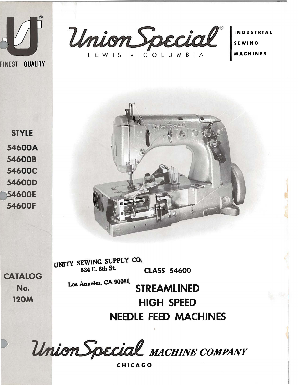
Page 1
®
INDUSTRIAL
SEWING
FINEST QUALITY
ST
YLE
54600A
00
00
8
C
546
546
546000
LEWIS
•
COLUMBIA
MACHINES
4600E
54600F
CATALOG
No.
120M
UNITY SEWING SUPPLY CO.
824
E.
8th St.
.__
'
CA
9001l
Loa
ngge,e•,
STREAMLINED
HIGH
NEEDLE
CLASS
FEED
54600
SPEED
MACHINES
MACHINE
CHICAGO
COMPANY
Page 2
Catalog
No.
120
M
The
furnished
54600
54600
54600
parts
at
LIST
CLASS
A
B
listed
list
First
c
OF
Styles
in
prices
Edition
PARTS
54600
54600
this
for
54600
54600
catalog
repairs
D
E
F
are
only.
Union
Rights
Copyright
by
Special
Reserved
1962
Machine
in
All
MACHINE COMPANY
INDUSTRIAL
Printed
SEWING
CHICAGO
in
MACHINES
U.S.A.
Co.
Countries
Page 3
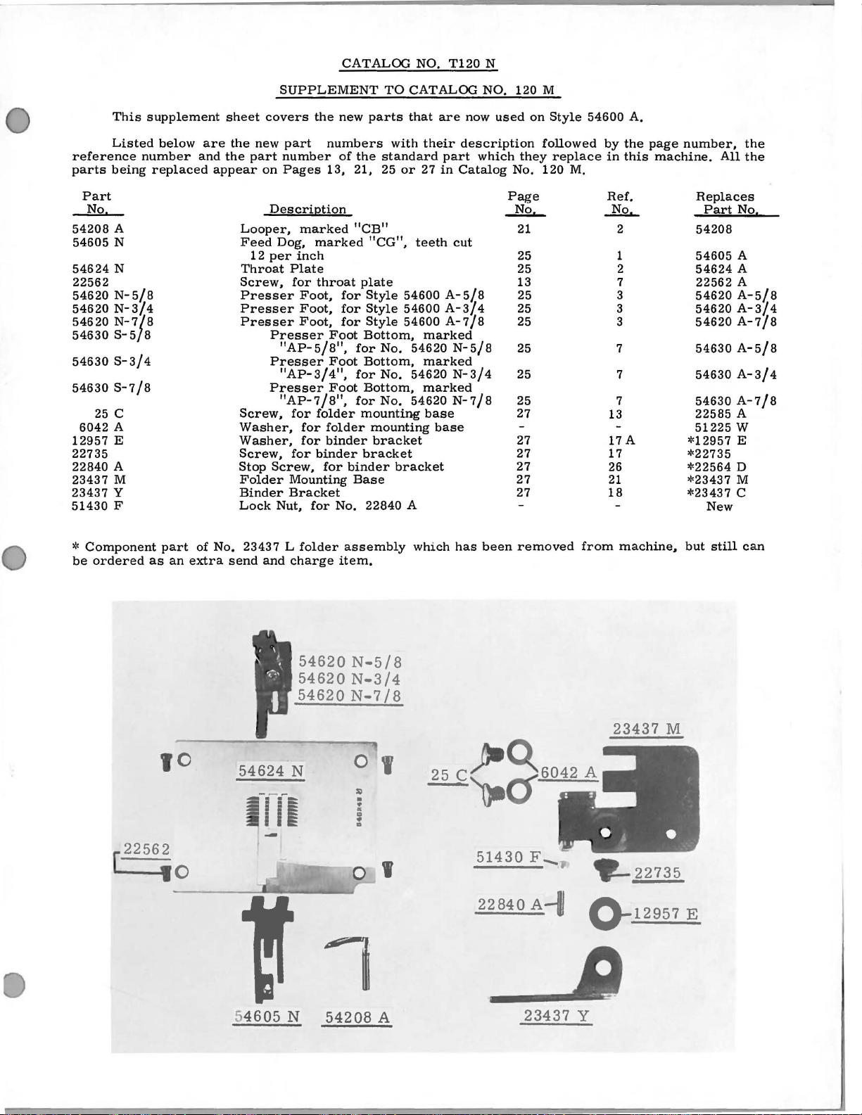
CATALOO
NO.
T120
N
This
Listed
reference
parts
Part
No
54208
54605
54624
22562
54620 N-5/8
54620
54620
54630
54630
54630
25 c
6042
12957
22735
22840
23437
23437
51430
number
being
A
N
N
N-3/4
N-7/8
S-5/8
S-3/4
S-7/8
A
E
A
M
y
F
supplement
below
replaced
are
and
sheet
the
the
appear
Looper,
Feed
Throat
Screw,
Presser
Presser
Presser
Screw,
Washer,
Washer,
Screw,
Stop
Folder
Binder
Lock
SUPPLEMENT
covers
new
part
part
number
on
Pages
Description
marked
Dog,
12
per
inch
Plate
for
Foot,
Foot,
Foot,
Presser
"AP-5/8",
Presser
"AP-3/4",
Presser
"AP-7/8",
for
for
for
for
Screw,
Mounting
Bracket
Nut,
the
new
numbers
of
13, 21, 25
"CB"
marked
throat
for
for
for
Foot
Foot
Foot
folder
folder
binder
binder
for
binder
Base
for
No.
TO
parts
with
the
standard
"CG",
plate
Style
Style
Style
Bottom,
for
No.
Bottom,
for
No.
Bottom,
for
No.
mounting
mounting
bracket
bracket
bracket
22840
CATALOO
that
are
now
their
description
or
part
27
in
Catalog
teeth
cut
54600 A-5/8
54600
A-3/4
54600
A-7/8
marked
54620
N-5/8
marked
54620
N-3/4
marked
54620
N-7/8
base
base
A
NO.
used
which
120M
they
No.
Page
~
21
25
25
13
25
25
25
25
25
25
27
27
27
27
27
27
on
Style
followed
replace
120
M.
54600
by
in
Ref.
_liQ...
13
17 A
17
26
21
18
2
1
2
7
3
3
3
7
7
7
A.
the
this
page
number,
machine.
All
Replaces
Part
54208
54605
54624
22562
54620
54620
54620
54630
54630
54630
22585
51225
*12957
*22735
*22564
*23437
*23437
New
the
the
No,
A
A
A
A-5/8
A-3/4
A-7/8
A-5/8
A-3/4
A-7/8
A
w
E
D
M
c
*
Component
be
ordered
[
part
as
10
2256;0
an
of
extra
No.
23437 L folder
send
and
54624
--rr1
--
charge
54620
54620
54620
N
assembly
item.
N-5/8
N-3/4
N-7
0
SOl
•
•
•
..
•
D
/8
I
I
which
has
been
removed
machine.
23437
M
but
still
can
from
~<:~6042A
51430
22840
F-
A-1/
~12957
E
I
5
4605
N
54208
A
23437
y
Page 4

0
0
Page 5
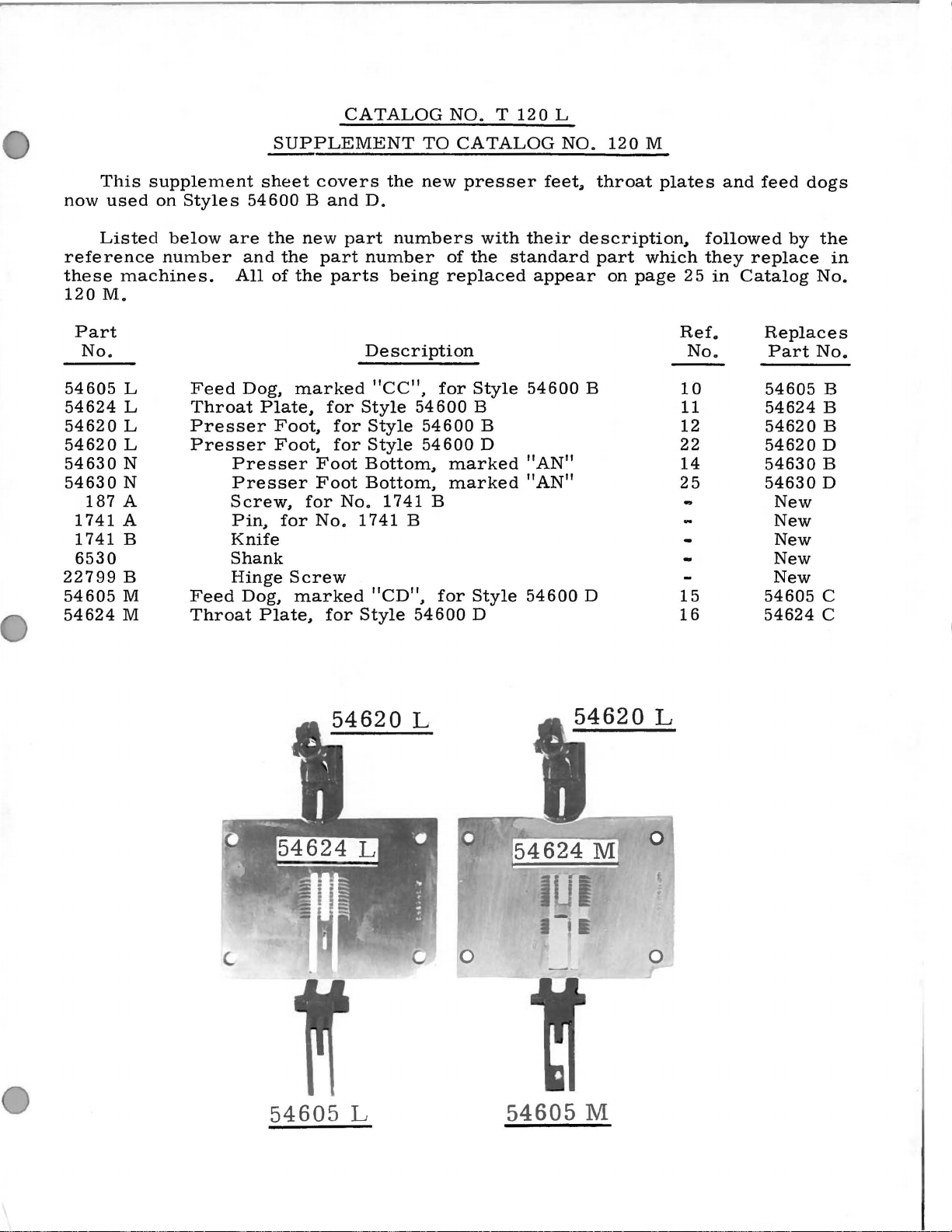
CATALOG
NO. T 120
L
This
now
used
Listed
reference
these
120M.
54605
54624
54620
54620
54630
54630
22799
54605
54624
Part
No.
187
1741
1741
6530
machines.
L
L
L
L
N
N
A
A
B
B
M
M
supplement
on
Styles
below
number
are
Feed
Throat
Presser
Presser
Presser
Presser
Screw.
Pin.
Knife
Shank
Hinge
Feed
Throat
SUPPLEMENT
sheet
54600 B and
the
and
All
Dog.
Plate.
Dog.
Plate.
new
the
of
the
marked
Foot.
Foot.
for
Screw
marked
covers
part
Foot
Foot
for
No.
D.
part
number
parts
Description
for
Style
for
Style
for
Style
Bottom.
Bottom.
No.
1741
for
Style
the
numbers
being
"CC".
1741
B
"CD".
TO
new
of
replaced
for
54600
54600
54600
marked
marked
B
for
54600
CATALOG
presser
with
their
the
standard
appear
Style
B
Style
D
54600
B
D
"AN"
"AN"
54600
NO.
feet~
120
M
throat
description~
part
on
B
D
plates
which
page
followed
they
25
in
Ref.
No.
10
11
12
22
14
25
15
16
and
replace
Catalog
feed
dogs
by
the
No.
Replaces
Part
54605
54624
54620
54620
54630
54630
54605
54624
No.
New
New
New
New
New
in
B
B
B
D
B
D
c
c
54605
L
54605
M
Page 6

Page 7
INSTRUCTIONS
FOR
FOR
MECHANICS
CATALOG
INSTRUCTIONS
TO
NO.
REPLACE
ON
PAGES
120
8,
M
9,
10,
11
Page 8
INSTRUCTIONS
FOR
MECHANICS
the
oil
oiling
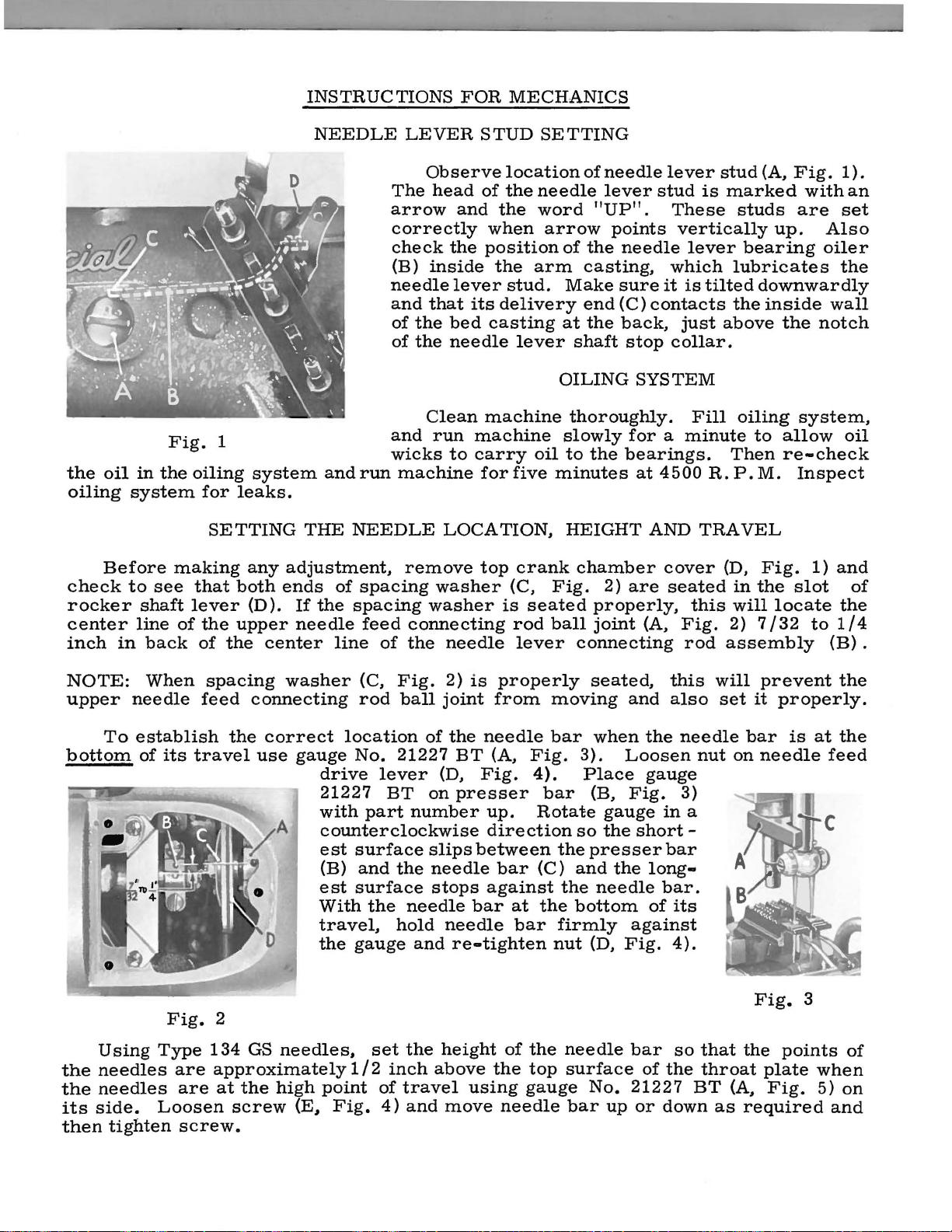
Before
check
rocker
center
inch
in
system
to
see
shaft
line
in
back
Fig.
the
oiling
making
that
lever
of
of
1
system
for
leaks.
SETTING
any
both
(D).
the
upper
the
center
NEEDLE
andrun
THE
adjustment.
ends
If
needle
of
the
line
NEEDLE
spacing
spacing
feed
LEVER
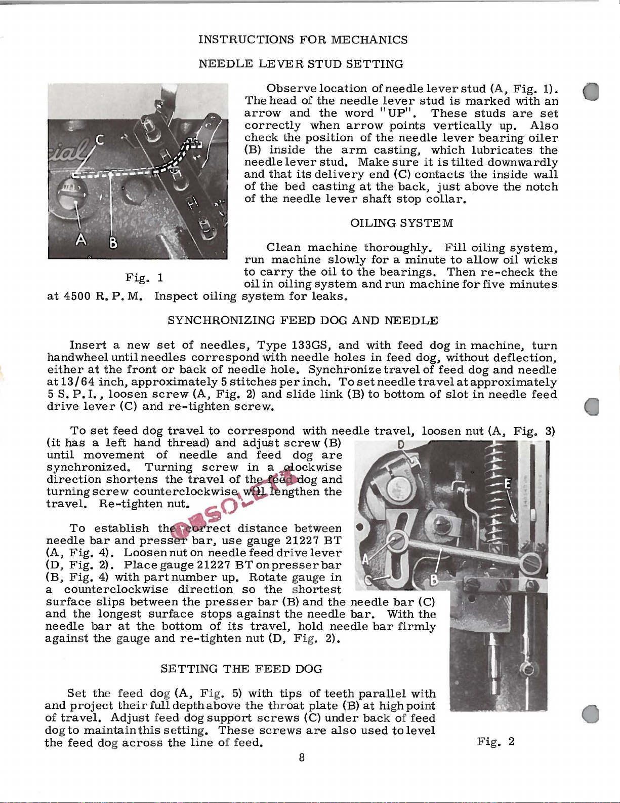
Observe
The
head
arrow
correctly
check
(B)
inside
needle
and
that
of
the
of
the
Clean
and
run
wicks
machine
remove
washer
connecting
of
the
STUD
location
of
the
and
the
when
the
position
the
lever
bed
needle
to
LOCATION,
washer
needle
stud.
its
delivery
casting
lever
machine
machine
carry
for
five
top
crank
(C,
is
seated
rod
lever
SETTING
of
needle
word
arrow
arm
oil
"UP".
of
the
casting.
Make
end
at
the
shaft
OILING
thoroughly.
slowly
to
the
minutes
HEIGHT
chamber
Fig.
properly,
ball
joint
connecting
needle
lever
points
sure
(C)
2)
lever
stud
These
vertically
needle
which
it
is
contacts
back.
stop
for a minute
bearings.
are
just
collar.
SYSTEM
at
4500
AND
cover
seated
(A.
Fig.
rod
stud
is
marked
studs
lever
Fill
this
bearing
lubricates
tilted
the
above
oiling
Then
R.P.M.
TRAVEL
(D.
in
will
2)
assembly
(A.
Fig.
up.
downwardly
inside
the
to
allow
re-check
Fig.
the
slot
locate
7/32
1).
with
are
set
Also
oiler
the
wall
notch
system.
oil
Inspect
1)
and
the
to
1/4
(B)
an
of
.
NOTE:
upper
To
bottom
Using
the
needles
the
needles
its
side.
then
When
needle
establish
of
Type
Loosen
tighten
its
travel
Fig.
are
are
screw.
spacing
feed
the
washer
connecting
correct
use
gauge
A
2
134
GS
needles,
approximately
at
the
high
screw
(E,
(C,
Fig.
rod
location
No.
21227
drive
21227
with
counterclockwise
est
(B)
est
With
travel,
the
point
Fig.
lever
BT
part
surface
and
the
surface
the
hold
gauge
set
1 I 2
inch
of
4)
ball
joint
of
(D,
on
number
slips
needle
stops
needle
and
the
height
above
travel
and
2)
the
needle
move
is
properly
from
needle
BT
(A.
Fig.
presser
up.
direction
between
bar
against
bar
at
bar
re-tighten
of
the
using
needle
moving
bar
Fig.
4).
bar
Rotate
the
(C)
the
the
firmly
nut
the
needle
top
surface
gauge
bar
seated,
when
3).
Loosen
Place
(B,
gauge
so
the
presser
and
the
needle
bottom
(D,
Fig.
No.
up
this
and
also
the
gauge
Fig.
in
short-
bar
long-
bar.
of
its
against
4).
bar
so
of
the
21227
or
down
will
set
needle
nut
3)
a
that
throat
BT
as
prevent
it
properly.
bar
on
needle
Fig.
the
plate
(A,
Fig.
required
is
at
3
points
when
5)
the
the
feed
of
on
and
Page 9
SETTING
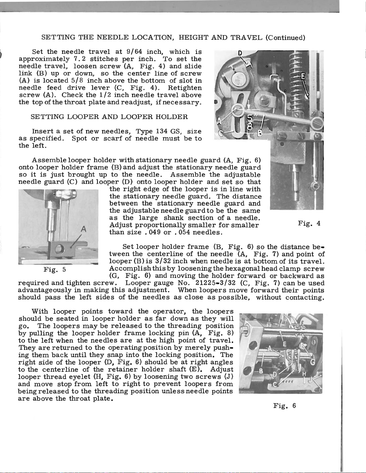
Set
the
approximately
needle
link
(A)
needle
screw
the
(B)
is
top
travel,
up
located
feed
(A).
of
the
THE
needle
7. 2 stitches
loosen
or
down,
5/8
drive
Check
the
throat
NEEDLE
travel
screw
so
inch
lever
1/2
plate
at
the
above
(C,
inch
and
LOCATION,
9/64
per
(A,
inch,
inch.
Fig.
center
the
bottom
Fig.
needle
readjust,
To
4)
line
4).
Retighten
travel
if
necessary.
HEIGHT
which
set
and
slide
of
screw
of
slot
above
is
the
in
AND
TRAVEL
(Continued)
SETTING
Insert a set
as
specified.
the
left.
Assemble
onto
looper
so
it
is
needle
required
Fig.
holder
just
guard
5
and
advantageously
should
pass
LOOPER
of
new
Spot
looper
frame
brought
(C)
and
tighten
in
making
the
left
AND
needles,
or
scarf
holder
up
looper
screw.
sides
LOOPER
Type
of
needle
with
stationary
(B)
and
adjust
to
the
needle.
(D)
onto
the
right
the
stationary
between
the
adjustable
as
the
Adjust
than
Set
tween
looper
edge
the
large
proportionally
size . 049
looper
the
(B)
Accomplish
(G,
Fig.
Looper
this
adjustment.
of
the
needles
HOLDER
134
GS,
must
the
Assemble
looper
of
needle
stationary
needle
shank
or
holder
centerline
is
3/32
this
by
6)
and
moving
gauge
size
be
to
needle
stationary
holder
the
looper
guard.
guard
section
smaller
. 054
needles.
frame
of
inch
when
loosening
No.
21225-3/32
When
as
close
guard
the
and
is
needle
to
(B,
the
needle
needle
the
the
holder
loopers
as
(A,
Fig.
needle
guard
adjustable
set
so
that
in
line
with
The
distance
be
guard
the
and
same
of a needle.
for
smaller
Fig.
is
6)
(A,
at
hexagonal
forward
(C,
move
possible,
6)
so
the
Fig.
7)
bottom
head
or
Fig.
forward
without
distance
and
of
its
clamp
backward
7)
can
their
contacting.
Fig.
point
travel.
screw
be
used
points
4
be-
of
as
With
should
go.
by
pulling
to
the
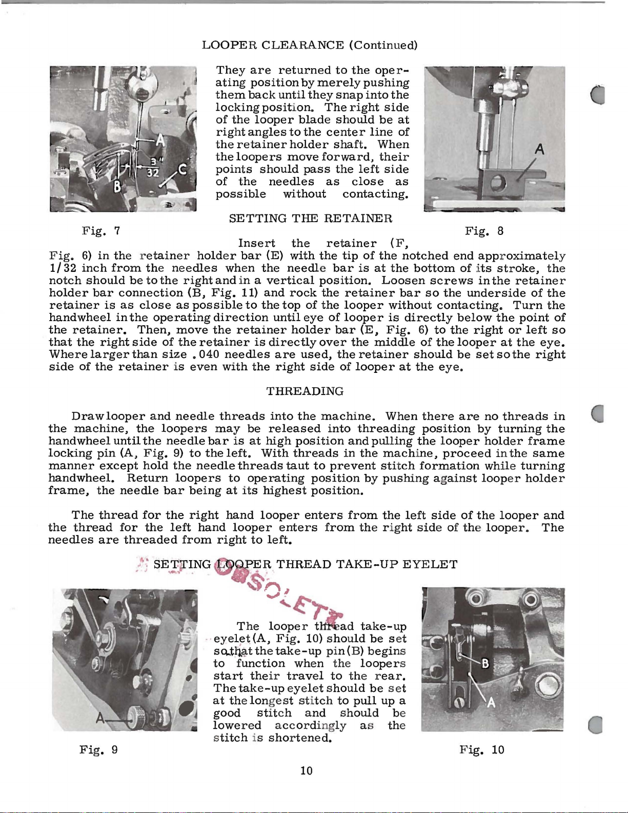
They
ing
them
right
to
the
looper
and
move
being
are
above
looper
be
seated
The
loopers
the
left
when
are
returned
back
side
of
centerline
thread
stop
released
the
looper
until
the
eyelet
from
to
throat
points
in
looper
may
the
needles
to
they
looper
of
the
(H,
the
plate.
toward
holder
be
released
holder
are
the
operating
snap
(D~
Fig.
retainer
Fig.
left
to
threading
frame
at
into
6)
6)
by
right
position
the
operator~
as
far
to
the
locking
the
high
position
the
locking
should
holder
loosening
to
prevent
unless
the
down
as
threading
pin
(A~
point
by
merely
position.
be
at
right
shaft
(E).
two
loopers
needle
loopers
they
position
Fig.
of
travel.
push-
angles
Adjust
screws
points
from
will
8)
The
(J)
Fig.
6
Page 10
The
right
looper
are
threaded
THREAD
thread
side
of
enters
TENSION
for
the
looper
from
from
the
the
right
right
and
left
to
RELEASE
hand
the
side
of
the
left.
looper
thread
looper.
(Continued)
enters
for
the
left
The
from
hand
needles
the
SETTING
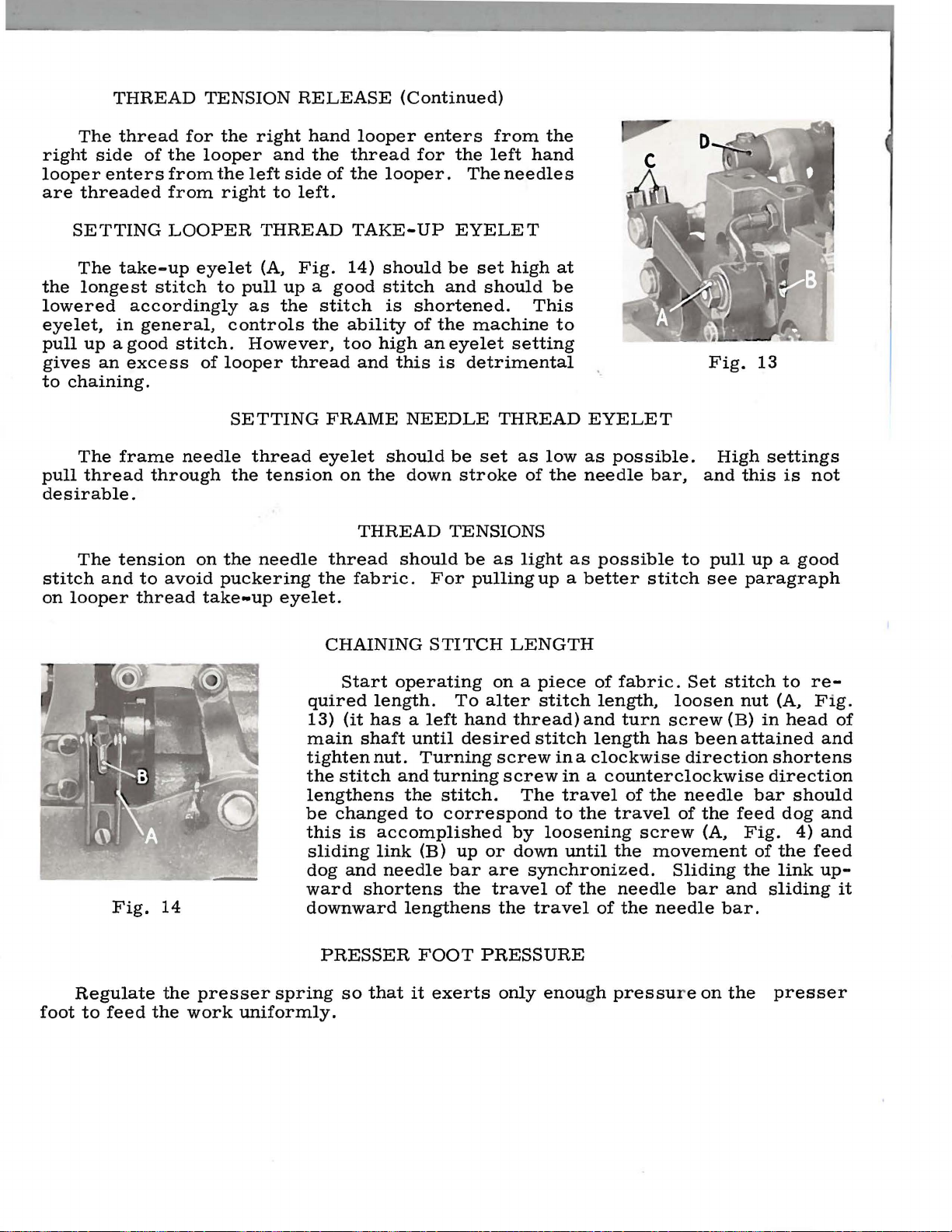
The
the
longest
lowered
eyelet,
pull
up a good
gives
to
pull
desirable.
stitch
on
an
chaining.
The
thread
The
and
looper
LOOPER
take-up
stitch
accordingly
in
general,
stitch.
excess
frame
tension
through
to
avoid
thread
needle
eyelet
to
pull
controls
of
looper
SETTING
the
on
the
puckering
take-up
THREAD
(A,
Fig.
up a good
as
the
the
However,
thread
thread
tension
needle
the
eyelet.
TAKE-UP
14)
should
stitch
stitch
FRAME
eyelet
thread
CHAINING
is
ability
too
high
and
should
on
the
THREAD
fabric.
this
should
EYELET
be
and
shortened.
of
the
machine
an
eyelet
is
detrimental
NEEDLE
be
down
stroke
TENSIONS
be
For
pulling
STITCH
set
high
should
setting
THREAD
set
as
of
as
light
LENGTH
at
be
This
to
EYELET
low
as
the
needle
as
possible
up a better
possible.
bar,
stitch
to
Fig.
High
and
pull
see
13
settings
this
is
not
up a good
paragraph
foot
Fig.
Regulate
to
feed
14
the
the
presser
work
quired
13)
main
tighten
the
lengthens
be
this
sliding
dog
ward
downward
spring
uniformly.
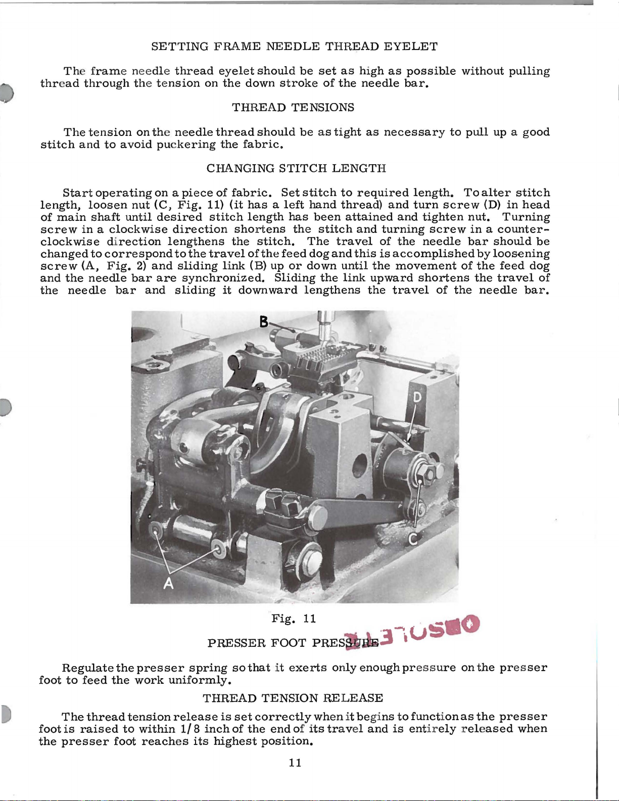
Start
(it
stitch
changed
and
PRESSER
so
operating
length.
has a left
shaft
nut.
is
accomplished
link
needle
shortens
that
To
until
and
the
lengthens
it
desired
Turning
turning
stitch.
to
correspond
(B)
up
bar
the
FOOT
exerts
on a piece
alter
hand
thread)
stitch
screw
screw
The
by
or
down
are
synchronized.
travel
the
travel
PRESSURE
only
of
fabric.
stitch
loosening
enou
length,
and
turn
length
ina
clockwise
in a counterclockwise
travel
to
until
of
the
the
of
gh
of
travel
screw
the
needle
the
pressu
Set
loosen
screw
has
direction
the
needle
of
movement
Sliding
bar
needle
r e
stitch
been
the
(A,
bar.
on
nut
(B)
in
attained
direction
bar
feed
Fig.
of
the
and
sliding
the
to
re-
(A,
Fig.
head
and
shortens
should
dog
and
4)
and
the
feed
link
up-
presser
of
it
Page 11
The
under
Looper
If
for
follow
"Setting
mechanical
"Setting
Holder",
Fig.
the
Looper
7
any
instructions
The
produces
reason
and
CHECKING
construction
Needle
the
under,
Looper
Location,
the
be
checked
travel.
the
direction
the
the
stroke
needle,
eye
the
Fig.
machine
Holder".
THE
and
the
Height
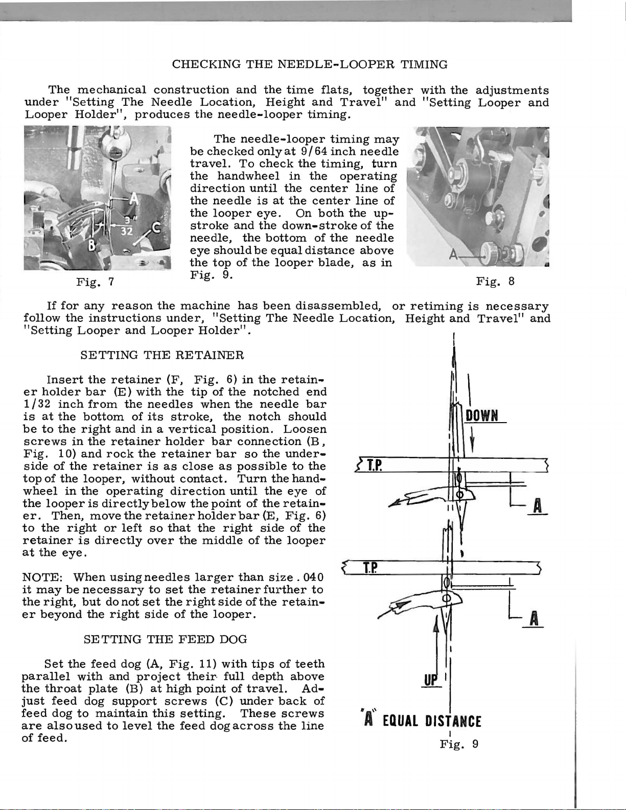
needle-looper
The
needle-looper
only
To
check
handwheel
until
needle
looper
should
top
9.
"Setting
and
the
of
has
is
eye.
the
bottom
be
equal
the
been
The
at
looper
NEEDLE-LOOPER
time
at
in
the
the
down-stroke
flats,
and
Travel"
timing.
timing
9/64
inch
needle
the
timing,
the
operating
center
center
On
both
of
distance
blade,
disassembled,
Needle
line
line
the
of
the
needle
above
Location,
together
may
turn
up-
the
as
TIMING
and
of
of
in
or
with
"Setting
retiming
Height
the
adjustments
Looper
Fig.
is
and
Travel"
1
and
8
necessary
and
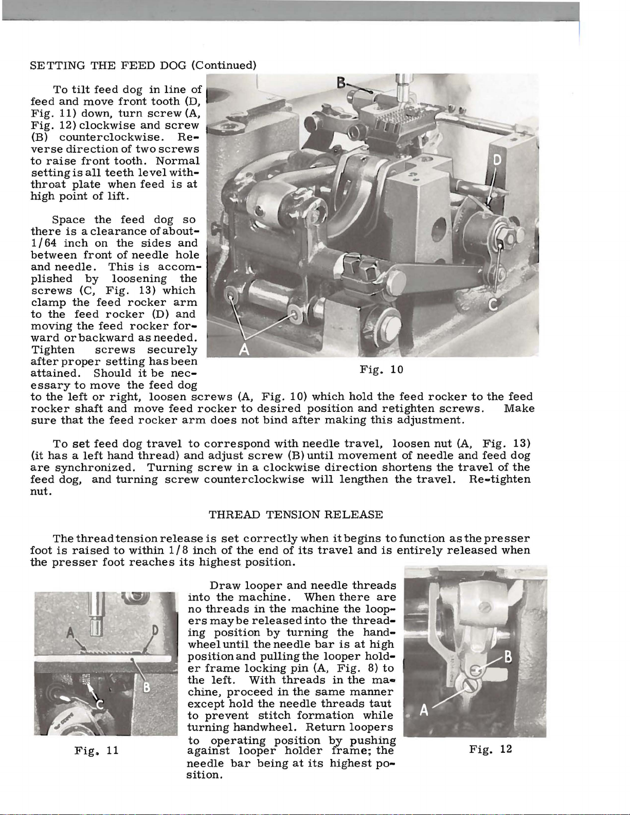
Insert
er
holder
1 I 32
is
be
screws
Fig.
side
top
wheel
the
er.
to
retainer
at
NOTE:
it
the
er
inch
at
the
to
the
1 0)
of
of
looper
Then,
the
the
may
right,
beyond
SETTING
the
bar
from
bottom
right
in
the
and
the
the
looper,
in
the
is
right
is
eye.
When
be
necessary
but
the
SETTING
retainer
(E)
and
retainer
rock
retainer
operating
directly
move
the
or
left
directly
using
do
not
right
THE
(F,
with
the
of
without
the
needles
its
stroke,
in a vertical
holder
the
retainer
is
as
direction
below
retainer
so
that
over
needles
to
set
set
the
side
THE
RETAINER
Fig.
tip
close
contact.
the
the
larger
the
right
of
the
FEED
of
when
the
position.
bar
bar
as
point
holder
the
right
middle
retainer
side
looper.
DOG
6)
the
until
in
the
retain-
notched
the
needle
notch
Loosen
connection
so
the
under-
possible
Turn
bar
than
of
of
of
the
the
the
the
retain-
(E,
Fig.
side
the
size.
further
retain-
end
bar
should
(B,
to
the
hand-
eye
of
6)
of
the
looper
040
to
\ I
DOWN
t
Set
the
feed
dog
(A,
parallel
the
throat
just
feed
are
of
feed
dog
also
feed.
with
plate
dog
to
used
and
project
(B)
support
maintain
to
level
at
high
screws
this
the
Fig.
11)
their
point
setting.
feed
dog
with
full
(C)
tips
depth
of
travel.
under
These
across
of
teeth
above
Ad-
back
screws
the
line
of
"A''
EQUAL
DISTANCE
I
Fig.
9
Page 12
SETTING
To
tilt
feed
and
move
Fig.
11)
down,
Fig.
12)
clockwise
{B)
counterclockwise.
verse
to
setting
throat
high
direction
raise
point
front
is
all
plate
THE
feed
teeth
when
of
lift.
FEED
dog
front
turn
of
two
tooth.
level
in
tooth
screw
and
Normal
feed
DOG
line
{D,
{A,
screw
Re-
screws
with-
is
at
{Continued)
of
Space
there
1 I 64
is a clearance
inch
between
and
needle.
plished
screws
clamp
to
the
the
moving
ward
or
Tighten
after
proper
attained.
essary
to
the
left
rocker
sure
that
To
set
{it
has a left
are
synchronized.
feed
dog,
nut.
the
on
front
This
by
loosening
{C,
Fig.
feed
feed
rocker
the
feed
backward
screws
setting
Should
to
move
or
right,
shaft
the
and
feed
feed
hand
and
feed
the
sides
of
needle
is
13)
rocker
rocker
as
securely
it
the
move
rocker
dog
travel
thread)
Turning
turning
dog
of
about-
hole
accom-
which
arm
{D)
and
for-
needed.
has
been
be
nee-
feed
loosen
feed
screw
so
and
the
dog
screws
rocker
arm
does
to
correspond
and
adjust
screw
counterclockwise
THREAD
(A,
Fig.
1 0)
to
desired
not
screw
bind
with
after
needle
{B)
position
until
in a clockwise
TENSION
which
making
travel,
movement
direction
will
lengthen
RELEASE
Fig.
hold
and
10
the
feed
retighten
this
adjustment.
loosen
of
shortens
the
rocker
screws.
nut
needle
the
travel.
to
the
(A,
Fig.
and
feed
travel
Re-tighten
feed
Make
13)
dog
of
the
The
foot
the
thread
is
raised
presser
Fig~
tension
to
foot
11
release
within
reaches
1 I 8
its
is
set
inch
of
highest
Draw
into
the
no
threads
ers
maybe
ing
position
wheel
position
er
frame
the
left.
chine,
except
to
prevent
turning
to
operating
against
needle
correctly
the
end
position.
looper
machine.
in
released
until
the
and
pulling
locking
With
proceed
hold
the
stitch
handwheel.
looper
bar
being
of
and
the
machine
by
turning
needle
pin
threads
in
the
needle
position
holder
at
when
its
it
travel
needle
When
into
there
the
the
bar
is
the
looper
{A,
Fig.
in
same
threads
formation
Return
by
frame;
its
highest
begins
and
threads
the
loop-
thread-
hand-
at
high
hold-
8)
the
rna•
manner
taut
while
loopers
pushing
sition.
to
is
are
to
the
po-
function
entirely
as
the
released
Fig.
presser
when
12
Page 13
The
50000
series
streamlined
FOREWORD
needle
feed
machines
covered
by
this
catalog
represent
bars
speed
lighter
reduces
machines
operations.
with
reservoir,
enable
Specials.
machines
and
and
running
pressure
Automatic
isolated
It
is
our
Union
the
latest
needle
production.
provide
our
The
covered
Special
bar
and
lubrication
mounting
has
made
constant
customers
following
design
driving
The
smoother
required
uniform
maintenance
in
this
representatives
of
mechanisms
new
to
lift
feeding
and a new
oil
pan
aim
to
to
secure
pages
catalog.
Union
light
operating.
base
furnish
illustrate
Special's
weight
the
presser foot.
and
filter
plate,
simple.
all
possible
will
be
make
parts
The
flatter
type
for
carefully
and
found
flat
bed
it
possible
and
light
oil
describe
in
weight
The
s-eams
return
returning
prepared
advantages
all
manufacturing
line.
needle
presser
needle
on
medium
pump,
filtered
the
to
Light
attain
bearings
feed
information
from
parts
feature
to
used
oil
the
used
weight
the
bar
in
centers,
presser
utmost
make
mechanism
of
heavy
to
use
in
weight
conjunction
the
which
of
Union
all
of
ready
in
them
these
main
will
the
to
cooperate
with
you
to
plan
and
estimate
requirements.
~MACHINE
3
Engineering
COMPANY
Department
Page 14

IDENTIFICATION
OF
MACHINES
the
Each
name
Union
plate
Standard
letter"
"Z".
to
the
Z".
When
standard
Styles
which
herein.
this
from
differs
This
class.
the
catalog
It
handwheel
Streamlined
Needle
and
System,
Feed
of
Needle
Feed,
Needle
Filter
and
Looper
Special
on
the
Style
numbers
Example:
only
minor
Style
of
machines
from
applies
can
also
Reference
operator's
is
toward
Flat
High
Bar
Driving
Type
Throw-out
Bar 7 3/4
machine.
number.
the
style
be
applied
to
position
the
Bed,
Throw,
Mechanism,
Oil
Inches.
machine
is
Style
have
"Style
changes
one
54600
are
Example:
similar
in
number,
APPLICATION
specifically
with
direction,
while
operator.
STYLES
One
or
Two
Needle
Return
Pump
for
Simplified
identified
numbers
or
more
A".
Special
made
"Style
construction
in
that
it
OF
to
the
discretion
such
as
seated
OF
MACHINES
Needle,
Bearing
Single
Reservoir
and
Oil
Threading,
by a Style
are
classified
letters
suffixed,
Style
in a standard
54600
are
grouped
contains
no
CATALOG
Standard
to
some
right,
at
the
left,
machine.
Needles
Crankshaft,
Enclosed
Siphon
Assembly,
Maximum
number
as
numbers
machine,
AZ".
letters.
Styles
Special
front,
Abreast,
Light
which
standard
but
is
never
stamped
and
contain
a
"Z"
under a class
Example:
of
machines
Styles
back,
Operating
of
machines
etc.,
direction
Independent
Weight
Automatic
Loopers
Work
Presser
Lubricating
in
Space
special.
contain
the
letter
is
suffixed
number
"54600
as
listed
are
given
Row,
Line
to
Right
into
the
11
in
of
Bar
With
•
54600 A Single
Machine
cation
standard
has
401-BSa-1/
widths
54600 B Single
medium
cation
weight
401-SSa-1.
54600 C Single
Hingedpresserfoot
to
the
left
(modified).
54600 D Single
heavy
weight
401-SSa-1.
54600 E Two
sleeves
of
light
401-LSc-2.
needle
throw-out
5
needle
materials.
needle
of
needle
needle
materials.
needle
to
Standard
machine
EFb-1
8,
7/8
machine
machine
with
for
machine
machine
medi
urn
binder,
(inverted)
or
Hinged
for
splitturned
guiding
for
Hinged
for
weight
gauges
for
binding,
1/4
inch
3/4
inch.
for
miscellaneous
presser
seaming
uptoeand
cord.
miscellaneous
presser
piecing
shirts
Nos.
16
hemming
hemmer
or
SSa-1.
couch
Seam
foot
sleeves,
and
similar
and
18.
and
and
Uses
seaming
foot
and
covers
a
5/32
specification
seaming
and
edge
joining
garments.
seaming
edge
guide.
selvage
operations
edge
with
inch
guide.
or
cord
operations
guide.
shoulders,
on
mattresses.
Seam
edge
Seam
without
groove
401-SSa-1
on
Seam
specification
and
Seam
specification
specifi-
binding,
on
light
specifi-
rope
in
bottom
or
welt.
SSk-1
medium
setting
to
to
54600 F Two
weltto
welt
guide
left
hand
needle
auto
seat
attachment.
needle.
machine
covers.
Seam
for
seaming,
Machine
Hinged
presser
specification
binding
has
combination
foot
401-BSd-2.
4
and
with
attaching a 1/8
3/4
inch
binder
1/8
inch
cord
inch
and
groove
diameter
1/8
inch
to
left
of
Page 15
NEEDLES
Each
number
The
size
measured
ively,
Standard
shank,
groove,
To
sample
on
label.
Selection
Thread
Union
denotes
number,
in
thousandths
the
type
round
chromium
have
needle,
A
should
Special
number
needle
point,
needle
complete
ofthe
formation.
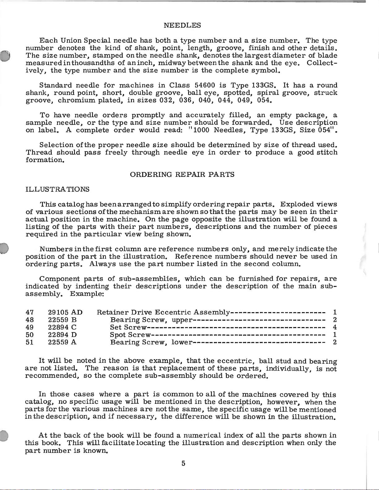
ILLUSTRATIONS
This
catalog
of
various
actual
listing
required
sections
position
of
the
in
the
in
parts
the
kind
stamped
for
short,
plated,
orders
or
the
type
proper
pass
has
been
of
the
freely
the
machine.
with
particular
needle
of
and
of
on
an
the
has
shank,
the
inch,
machines
double
in
sizes
promptly
and
order
would
needle
through
ORDERING
arranged
mechanism
their
part
view
both a type
point,
needle
midway
size
number
in
groove,
032, 036,
size
number
read: 111000
size
needle
to
simplify
are
On
the
numbers,
being
shank,
Class
and
accurately
should
REPAIR
shown
page
shown.
number
length,
denotes
between
is
the
54600
ball
eye,
040,
should
Needles,
be
determined
eye
in
PARTS
ordering
so
that
opposite
descriptions
and a size
groove,
the
the
shank
complete
is
Type
spotted,
044, 049,
filled,
be
forwarded.
order
repair
the
parts
the
illustration
finish
largest
and
symbol.
133GS.
spiral
054.
an
Type
by
to
produce
parts.
may
and
the
number.
and
diameter
the
groove,
empty
Use
133GS,
size
of
Exploded
be
number
The
other
details.
of
eye.
It
Collect-
has a round
package,
description
Size
thread
a
good
seen
will
be
in
found
of
type
blade
struck
11
054
used.
stitch
views
their
pieces
a
•
a
Numbers
position
ordering
of
the
parts.
Component
indicated
by
assembly.
It
not
29105
22559
22894
22894
22559
will
be
listed.
47
48
49
50
51
are
recommended,
In
those
catalog,
parts
in
the
no
for
the
description,
in
the
first
part
Always
parts
indenting
Example:
AD
B
c
D
A
noted
The
so
the
cases
specific
various
and
column
in
the
use
of
sub-assemblies,
their
Retainer
Bearing
illustration.
are
reference
the
part
descriptions
Drive
Eccentric
Screw,
numbers
Reference
number
which
under
listed
can
the
numbers
in
be
description
Assembly-----------------------
upper--------------------------------
SetScrew-------------------------------------------
SpotScrew------------------------------------------
Bearing
in
the
reason
complete
where
usage
machines
if
necessary,
above
is
a
part
will
Screw,
lower--------------------------------
example,
that
replacement
sub-assembly
is
common
be
mentioned
are
not
the
the
difference
that
to
in
same,
the
eccentric,
of
these
should
all
the
description,
the
will
be
of
the
specific
only,
should
the
second
furnished
parts,
ordered.
machines
usage
be
shown
and
merely
never
column.
for
of
ball
stud
individually,
however,
will
in
the
indicate
be
repairs,
the
main
and
covered
be
mentioned
illustration.
used
sub-
bearing
is
by
when
the
in
are
1
2
4
1
2
not
this
the
At
the
this
part
back
book.
number
This
is
of
the
will
facilitate
known.
book
will
locating
be
found a numerical
the
illustration
index
5
and
description
of
all
the
parts
when
shown
only
in
the
Page 16
IDENTIFYING
PARTS
Where
some
identification
Part
appear.
IMPORTANT!
OF
MACHINE
Success
Union
Company.
to
the
Maximum
Genuine
repair
your
guarantee
the
of
the
numbers
Special
its
most
efficiency
parts
construction
smaller
letter
represent
ON
FOR
in
subsidiaries
approved
needles
are
WHICH
USE
the
operation
Needles
stamped
of
the
parts,
is
stamped
ALL
GENUINE
and
and
scientific
and
durability
are
packaged
highest
permits,
and
on
the
same
ORDERS,
PART
Repair
with
IS
NEEDLES
of
these
authorized
principles,
with
the
quality
each
those
in
Parts
are
Union
part
where
to
distinguish
part,
PLEASE
ORDERED.
machines
distributors.
assured.
the
in
materials
TERMS
is
the
regardless
INCLUDE
AND
as
furnished
and
are
labels
Special
stamped
construction
the
REPAIR
can
be
They
made
marked
trade
and
mark.
workmanship.
with
part
of
catalog
PART
PARTS
secured
by
Union
are
with
~
its
part
does
from
NAME
only
Special
designed
the
utmost
Each
number.
not
permit,
similar
in
which
AND
with
according
precision.
.
trade
On
an
ones.
they
STYLE
genuine
Machine
Genuine
mark
is
Prices
are
forwarded
insured
insurance.
The
must
Saybolt
sight
the
than
throw-out
is
on.
reservoir,
reservoir
hand
be
viscosity
Oil
is
gauge
red
The
an
occasional
required.
A
daily
which
wheel.
are
at
unless
oil
has
filled
filled
on
lines
machine
pin,
check
has
making
may
strictly
the
buyer's
otherwise
been
before
at
the
on
and
gone
be
drained
of
200
the
front
the
is
almost
drop
looper
before
through
too
drained
net
cash
directed.
beginning
to
250
spring
of
the
gauge.
entirely
of
oil
holder
the
morning
frequent
at
and
risk
f.
OILING
from
to
seconds
cap
in
machine.
The
at
frame
the
machine,
oilings
the
subject
o.
b.
shipping
A
charge
AND
the
operate.
the
automatically
both
start
plug
THREADING
machine
at
100°
top
cover,
The
capacity
bearings
locking
should
is
unnecessary.
screw
to
change
point.
is
made
before
Use a straight
Fahrenheit.
and
oil
level
of
the
lubricated,
of
the
pin,
as
be
made
filtered
in
the
and
main
without
Parcel
to
shipping,
the
oil
should
oil
reservoir
retainer
indicated
and
pumped
Excessive
frame
notice.
Post
cover
and
mineral
.
level
be
maintained
and
holder,
in
oil
added
back
directly
All
shipments
the
postage
the
is
checked
is
no
oiling,
oiling
if
into
oil
in
shipments
reservoir
oil
with
at
between
12
ounces.
other
the
looper
diagram.
required.
the
main
the
main
under
are
and
a
the
the
The
machine
manner.
a
plane
left.
accompanying
is
threaded.
Please
at
right
notethat
angles
drawing
Two
the
to
the
also
needle
needle
direction
shows
machines
is
inserted
of
line
6
the
are
of
manner
threaded
in
the
feed,
in
in
needle
and
is
which a single
substantially
holder
threaded
with
the
the
from
needle
same
eye
right
in
to
Page 17
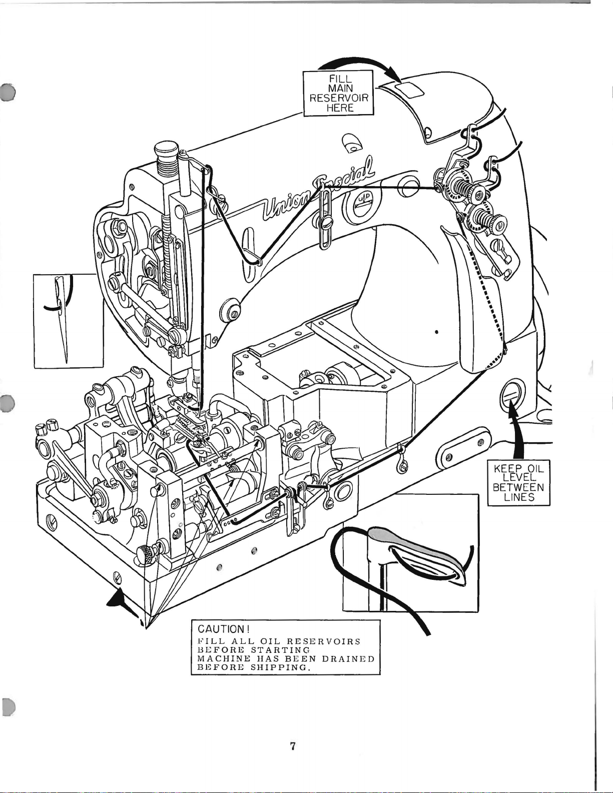
FILL
MAIN
RESERVOIR
HERE
CAUTION!
FILL
BEFORE
MACHINE
BEFORE
ALL
OIL
STARTING
HAS
SHIPPING.
RESERVOIRS
B E
EN
DRAINED
7
Page 18
INSTRUCTIONS
FOR
MECHANICS
at
4500
Insert
hand
either
at
13/64
5
S.
P.
drive
R.
wheel
at
the
inch,
I. , loosen
lever
NEEDLE
Fig.
P.M.
a
new
until
front
(C)
1
Inspect
SYNCHRONIZING
set
needles
or
approximately 5 stitches
screw
and
re-tighten
oiling
of
needles,
correspond
back
(A,
of
Fig.
The
arrow
correctly
check
(B)
needle
and
of
of
run
to
oil
system
Type
needle
2)
screw.
LEVER
Observe
head
and
the
inside
lever
that
the
bed
the
needle
Clean
machine
carry
in
oiling
for
FEED
133GS,
with
needle
hole.
per
and
slide
STUD
location
of
the
needle
the
word
when
position
the
arm
stud.
its
delivery
casting
lever
machine
slowly
the
oil
to
system
leaks.
DOG
and
holes
Synchronize
inch.
To
link
SETTING
of
needle
lever
"UP".
arrow
Make
OILING
the
AND
set
(B)
points
of
the
casting,
sure
end
(C)
at
the
shaft
thoroughly.
for a minute
bearings.
and
run
NEEDLE
with
in
feed
travel
needle
to
bottom
lever
stud
These
vertically
needle
which
it
is
contacts
back,
stop
SYSTEM
feed
just
collar.
machine
dog
dog,
of
feed
travel
of
stud
is
marked
studs
lever
Fill
Then
without
slot
bearing
lubricates
tilted
the
above
oiling
to
allow
re-check
for
five
in
machine,
dog
at
approximately
in
(A,
Fig.
1).
with
an
are
set
up.
downwardly
inside
deflection,
and
needle
Also
oiler
the
notch
system,
oil
wicks
minutes
turn
needle
feed
the
wall
the
To
set
(it
has a left
until
synchronized.
direction
turning
travel.
needle
(A,
(D,
(B,
a
surface
and
needle
again
and
of
dogto
the
movement
shortens
screw
Re-tighten
To
establish
bar
Fig.
4).
Fig.
2).
Fig.
4)
counterclockwise
slips
the
longest
bar
st
the
Set the
project
travel.
feed dog
Adjust feed
maintain
feed
dog
travel
hand
counterclockwis
and
Loosennuton
Placegauge21227
with
between
at
the
gauge
feed dog
their
across
thread)
of
Turning
the
nut.
th
press
part
surface
bottom
and
SETTING
full
this
setting.
the
needle
travel
bar,
number
direction
the
re-tighten
(A, Fig. 5)
depth
dog
line
to
correspond
and
adjust
and
feed
screw
~Q
rect
needlefeeddrivelever
presser
stops
of
above
support
in
a
of
th
~
.._..
distance
use
gauge
BTonpresserbar
up.
Rotate
so
the shortest
bar
against
its
travel,
nut
(D,
THE
These
of
FEED
with
the thr
screws
screws
feed.
with
screw
dog
ockwise
og
ngthen
between
21227
gauge
(B)
and
the
needle
hold
F ig. 2).
DOG
tips
oat
(C)
are
8
of
plate
needle
(B) 0
are
and
the
BT
in
the
needle
teeth
(B)
under
also
travel,
needle
bar.
bar
parall
at high
bac
used
bar
With
k of f
tolevel
loosen
(C)
the
firmly
el with
poi
nt
eed
nut
(A,
Fig.
Fig.
2
3)
Page 19

SETTING
THE
FEED
DOG
(Continued)
Space
clearance
teeth
the
of
pass
accomplished
clamp
and
Spot
the
moving
Fig.
or
scarf
feed
4
Assemble
holder
needle.
and
The
be
for
frame
set
so
distance
the
same
smaller
Assemble
that
feed
at
least
beyond
by
rocker
the
feed
of
needle
looper
(B)
and
the
between
as
the
than
size • 049
dog
in
1/64
the
rear
loosening
arm
rocker
Tighten
setting
necessary
or
right,
hold
the
shaft
and
position
sure
bind
that
after
Insert
must
holder
adjust
the
adjustable
right
edge
the
stationary
large
the
throat
inch a tall
of
the
the
screws
to
the
forward
screws
has
been
to
move
loosen
feed
screws
rocker
move
and
re-tighten
the
feed
making
SETTING
a
set
be
to
and
the
stationary
needle
of
the
shank
section
or • 054
plate
points
presser
(C,
feed
or
rocker
backward
securely
attained.
the
feed
(A,
onto
feed
rocker
rocker
this
LOOPER
of
new
the
left.
stationary
needle
guard
looper
is
needle
of a needle.
needles.
so
there
and
so
foot.
Fig.
(D,
as
after
Should
dog
to
Fig.
the
feed
to
screws.
arm
adjustment.
AND
needles,
needle
guard
(C)
in
line
guard
the
rear
This
3)
which
Fig.
needed.
proper
it
the
11)
which
rocker
desired
Make
does
Type
guard
and
with
and
the
Adjust
is
a
is
3)
be
left
not
LOOPER
133GS,
(A,
so
it
is
looper
the
(D)
stationary
adjustable
proportionally
Fig.
HOLDER
size
Fig.
just
brought
onto
needle
3
as
6)
onto
looper
needle
specified.
looper
up
to
the
holder
guard.
guard
to
smaller
Set
looper
centerline
3/32
inch
Accomplish
screw
ward
(G,
as
required
21225-3/32
making
Set
this
the
Fig.
holder
of
needle
when
Fig.
this
(C,
needle
by
6)
and
Fig.
adjustment.
SETTING
height
of
6
frame
(A,
loosening
moving
and
tighten
7)
HEIGHT
the
needle
(B,
Fig.
Fig.
is
at
7)
the
the
the
and
bottom
hexagonal
holder
screw.
can
be
used
OF
NEEDLE
bar
so
needles
are
inchabovethetop
throat
using
screw
required
should
go.
the
plate
gauge
(E,
and
With
looper
be
Check
retainer
threading
threading
locking
the
high
pin
point
6)
so
distance
point
of
point
forward
Looper
advantageously
BAR
that
the
approxi
su
when
No.
Fig.
21227
then
the
2)
tighten
LOOPER
points
seated
to
see
in
that
holder
position.
position
(A,
Fig.
of
travel.
between
looper
head
of
or
(B)
travel.
clamp
back-
gauge
points
.J;I;l
~
of
a
W~J..Ii\
needles
BT
(A,
and
move
screw.
CLEARANCE
toward
looper
bar
The
by
9)
holder
the
loopers
(E.
loopers
pulling
to
the
is
No.
in
the
are
Fig.
needle
Fig.
left
L£T
at
8)
the
as
6)
may
the
when
.--~
---·
~
the
high
on
its
bar
operator.
far
down
clear
the
when
be
looper
the
5
·
point
side.
up
or
the
as
they
underside
released
released
holder
needles
of
travel
Loosen
down
loopers
will
to
to
frame
are
as
of
the
the
at
9
Page 20
LOOPER
CLEARANCE
(Continued)
Fig.
Fig.
1/32
notch
holder
retainer
hand
the
that
Where
side
6)
inch
wheel
retainer.
the
of
7
in
the retainer
from
should
bar
connection
is
as
in
right
larger
the
retainer
the
be
to
close
the
Then,
side
than
holder
needles
the
right
(B,
as
possible
operating
move
of
the
size • 040
is
even
They
ating
them
locking
of
the
right
the
the
loopers
points
of
possible
SETTING
when
and
Fig.
direction
the
retainer
needles
with
are
position
back
position.
looper
angles
retainer
should
the
needles
Insert
bar
(E)
the
in a
vertical
11)
and
to
the
until
retainer
is
directly
the
returned
by
merely
until
they
blade
to
the
holder
move
pass
without
THE
the
with
the
needle bar
position.
rock
top
of
eye
holder
over
are
used,
right
side
to
the
ope
pushing
snap
into
The
right
should
center
shaft.
forward,
the
as
RETAINER
retainer
the
the
of
bar
the
line
When
left
close
contacting.
tip
of
is
at
retainer
looper
looper
(E,
the
middle
retainer
of
looper
r-
the
side
be
at
of
their
side
as
(F,
the
notched
the
Loosen
bar
without
is
directly
Fig.
at
bottom
screws
so
the
contacting.
6)
to
of
the
should
the
eye.
Fig.
end
of its
below
the
looper
be
8
approximately
stroke,
in
the
underside
the
right
set
so
retainer
Turn
point
or
at
the
the
A
of
left
right
the
the
the
of
so
eye.
Drawlooper
the
machine,
hand
wheel
locking
manner
handwheel.
frame,
the
needles
pin
the
The
thread
Fi
g. 9
except
thread
are
the
until
the
(A,
Fig.
hold
Return
needle
for
for
the
threaded
and
needle
loopers
needle
9)
to
the
loopers
bar
being
the
right
left
from
~
SET.- ING
THREADING
threads
may
bar
the
left.
needle
at
hand
hand
right
(
.&;j
\,11
is
threads
to
looper
~
\l:o
into
be
released
at
high
With
operating
its
highest
looper
to
left.
·
;u:
ER
THREAD
the
position
threads
taut
enters
enters
~~~
--"
i...
e-'r.
The
··
eyel~HA,
so..th
to function
start
The
at the
good
lowered a ccor dingly
titch
s
loope
~
t
the take-up pin (B )
the
ir
take-up
longest stitch
st
itch a
is
sho
r t
Fi
g. 10) shou
wh
trav
eyelet s
rt ene
machine.
into
threading
and
in
the
to
prevent
position
position.
from
en
el
to
nd should
d.
by
from
the
TAKE-UP
ad
take-up
ld
begin
the
looper
the r
hould
to
pull
a s
When
pulling
machine,
stitch
pushing against
the
r i
be
s et
ear.
be set
up
th
there
position
the
formation
left
ght
side
EYELET
s
s
a
be
e
looper
side
are
by
proceed
of
the
of the
F
ig.
no
threads
turning
holder
in the
while turning
loop
er
looper
looper
10
the
frame
same
holder
and
.
The
in
10
Page 21
SETTING
FRAME
NEEDLE
THREAD
EYELET
The fram
thread
through the t e
The
stitch
and
Start
length,
of
main
screw
in a clockwise
clockwise
changed
screw
and
the
(A,
the
needle
e needle thread
tension
to
avoid puc
operating
loosen
shaft
to
until
di
rection
correspond
Fig.
needle
bar
on the
on a piece
nut
(C,
desired
2)
and
bar
are
and
eyelet
nsion
on
needle
kering
thread
the
CHANGING
of
Fig.
11)
stitch
direction
lengthens
to
the
travel
sliding
synchronized.
sliding
should
the
down
THREAD
should
fabric.
fabric.
(it
has a left
length
shortens
the
stitch.
of
link
(B)
it
downward
stroke
STITCH
Set
the
feed
up
Sliding
be
set
as
of
the
TENSIONS
be
as
tight
LENGTH
has
the
or
stitch
hand
The
dog
down
to
thread)
been
stitch
travel
and
until
the
lengthens
high
needle
as
required
attained
and
this
the
link
upward
the
as
possible
bar.
necessary
length.
and
turn
and
tighten
turning
of
the
is
accomplished
screw
needle
movement
shortens
travel
to
screw
of
the
without
pull
To
nut.
up a
alter
(D)
pulling
in
Turning
in a counter-
bar
should
by
loosening
of
the
feed
the
travel
needle
good
stitch
head
be
dog
of
bar.
Regulatethepresser
foot
to
feed
The
thread
foot
is
raised
the
presser
the
tension
to
foot
work
within
reaches
spring
uniformly.
THREAD
release
1/8
inch
its
highest
sothat
is
set
of
it
TENSION
correctly
the
end
position.
exerts
when
of
its
onlyenoughpr
RELEASE
it begi
trav
el
11
ns
and
ess
ure
onthe pres
to
function
is
entirely released
as
the
ser
presser
when
Page 22

3
12
Page 23

MAIN
FRAME,
MISCELLANEOUS
COVERS
AND
PLATES
Ref.
No.
1
2
3
4
5
6
7
8
9
10
11
12
13
14
15
16
17
18
19
20
21
22
23
24
25
26
27
28
29
30
31
32
33
34
35
36
37
38
39
40
41
42
43
44
45
.
45A
46
47
48
49
50
51
51A
52
53
54
55
56
57
58
59
60
61
62
63
64
65
54401
54601
22839 c
80
22574
22562
22839
54280
52882
52882
22848
22733
41394
22585
22524
53782
52882
22548
52882
52882
22541 B
52882
39582
52882
50-789
52882
90
52882
51282
90
52882
93
B21375
98
52
51291
158
22585
39267
668-28
668-29
54282
20
22848
294
54682
54682
54682
22569
12934
54637
54682
22528
22513
35731
22517
53137
95
22848
20
539
22889 A
22784
54670
22891
719
Part
No.
A
M
L
B
A
A
B
K
AE
u
AD
L
AC
AA
p
AE
y
AH
A
A
A
B
c
B
A
c
A
B
c
c
A
F
A
F
A
Blk.
Description
Cloth
Plate,
Cloth
Plate,
Screw
Screw
Screw
Throat
Screw
Screw
Throat
Gasket--------------------------------------------------------
Oil
Reservoir
Screw
PlugScrew----------------------------------------------------
Gasket,
Screw
Screw
Oil
Gasket-------------------------------------------------------Screw
Crank
Gasket--------------------------------------------------------
Screw
Crank
Gasket-------------------------------------------------------Needle
Screw
Baffle
Screw
Belt
Screw
Thread
Looper
Thread
Screw
Looper
Oil
VVasher-------------------------------------------------------
Screw
Screw
Head
Head
Screw
Nut----------------------------------------------------------Guide
Needle
Needle
Screw
Press-er
Screw
Pin,
PlugScrew----------------------------------------------------
Screw
VVasher------------------------------------------------------Frame
Adaptor
Screw
Needle
Screw,
Screw
--------------------------------------------------------
Reservoir
--------------------------------------------------------
Chamber
--------------------------------------------------------
Chamber
OilCap---------------------------------------------------Oil
Oil
Oil
Screw-----------------------------------------------------
--------------------------------------------------------
Plate
--------------------------------------------------------
Guard---------------------------------------------------
--------------------------------------------------------
--------------------------------------------------------
Eyelet
Eyelet-----------------------------------------------------
Shield-----------------------------------------------------
--------------------------------------------------------
--------------------------------------------------------
Cover---------------------------------------------------
Felt
Cover
--------------------------------------------------------
Stud
--------------------------------------------------------
--------------------------------------------------------
for
--------------------------------------------------------
--------------------------------------------------------
--------------------------------------------------------
for
Styles
for
Style
--------------------------------------------------------
--------------------------------------------------------
-------------------------------------------------------Plate
(See
--------------------------------------------------------
-------------------------------------------------------Plate
Support-------------------------------------------
Back
--------------------------------------------------------
for
plug
screw-----------------------------------------
--------------------------------------------------------
Cap
Cap
Drip
Lever
Eyelet,
Thread
Eyelet,
Thread
Liner-------------------------------------------------
Bar
Bar
Eyelet
Screw-------------------------------------------------
Thread
for
Top
Cover,
Cover,
Torsion
Hinge
Plate----------------------------------------------
Bearing
---------------------------------------------------
for
Guard------------------------------------------
for
Pull-off
Locking
Gasket---------------------------------------------
Support---------------------------------------------
Frame
Frame
Bar
Connection
needle
bar
-------------------------------------------------
Take-up
61985 A --------------------------------------------
54600
54600
Page
Cover
Cover
Spring--------------------------------------
Pin
------------------------------------------
Oiler-------------------------------------
Styles
Styles
Ring
Guard--------------------------------------Guide
frame
B, C,
A-----------------------------------
21)
--------------------------------------
--------------------------------------
---------------------------------------
lower-----------------------------------
upper-----------------------------------
54600
54600
Eyelet
----------------------------------------
Stud-----------------------------------
Guide
--------------------------------------
VVire------------------------------------
D,
E,
F----------------------
A,
B, C, D ----------------------
E, F ----------------------------
----------------------------------
Plate-----------------------------
Amt.
Req.
1
1
2
3
1
1
4
3
1
1
1
9
1
2
2
7
1
1
4
1
1
3
1
1
1
1
1
2
1
1
2
1
2
1
4
3
1
3
1
1
2
2
1
3
3
3
1
1
1
2
1
1
1
1
4
2
1
1
1
1
1
1
1
1
1
1
2
13
Page 24

A
"
F..
:·
.,.-
.
.....
A B
~~
51
52
C D
~53
E
~$
55
I
~~
~52
~52
~52
5
8 7
14
Page 25

MAIN
FRAME,
BUSHINGS
AND
MISCELLANEOUS
OILING
PARTS
Ref.
No.
1
2
3
4
5
6
7
8
9
10
11
12
13
14
14A
15
16
17
18
19
20
21
22
23
24
25
26
27
28
29
30
31
32
33
34
35
36
37
37A
37B
38
39
40
41
42
43
44
45
46
47
48
49
50
51
52
53
54
55
56
57
58
59
60
Part
No.
51493 K
531
643-127
51493 AG
51493 D
51493
E
51493
AH
50-294
22569 B
51493
BE
51493 AN
22645
H-64
22823
A
51295
A
22823 B
51493
AY
51493 BG
52836 R
51493
BK
51242
z
51242
52836
52890
51290
51242
54293
54293 A
52894
51257
54694
22569 c
54694
22706 A
51294
21212
52883
51294
22729 B
51294
22729 A
21657
52891
22539 H
22571 A
35178
22889
22889
R
p
c
T
s
90
AB
AA
660-136
258 A
666-217
666-218
20
A
666-99
N
R
u
666-201
666-209
643-263
K
X
B
50-648
666-111
666-179
666-118
666-65
D
666-114
D
c
Blk.
Blk.
Blk.
Blk.
Description
Pump
Driven
Screw-----------------------------------------------------
Gasket--------------------------------------------------------
Pump
Oil
Driving
Oil
Screw
Filter
Screw
Screw
Mounting
Screw
Oil
Base Plate
Looper
Lint
Looper
Looper
Feed
Main
Main
Looper
Feed
Take-up
Screw
Oil
Presser
Oil
Oil
Horizontal
Screw
VVasher-------------------------------------------------------
Oil
Oil
PlugScrew---------------------------------------------------Oil
Locking
Presser
Oil
Screw
Release
Crankshaft
Lucite
Plug
PlugScrew----------------------------------------------------
Oil
VVedge
Oil
Oil
Spring,
Oil
Adaptor
Adaptor
Housing-------------------------------------------------
Pump
Pump
Pin
--------------------------------------------------------
Cap
VVasher,
--------------------------------------------------------
--------------------------------------------------------
--------------------------------------------------------
Pan
Filter
Rocker
Shaft
Bushing,
Shaft
Bushing,
Shaft
Lift
--------------------------------------------------------
Tube
Tube,
Nut
Attraction
Siphon
--------------------------------------------------------
Tube
VVick,
Tube
Siphon
Felt
Felt
Siphon----------------------------------------------------Screw----------------------------------------------------Clamp,
--------------------------------------------------------
Oil
Screw----------------------------------------------------
VVick,
Pin
Wick,
VVick,
VVick,
Gear---------------------------------------------
Driving
Shaft
Housing
------------------------------------------------------Assembly-------------------------------------------
Isolator----------------------------------------------
Assembly----------------------------------------------
Felt------------------------------------------------
Rocker
Screen
Drive
Drive
Bushing,
upper
Bushing,
Drive
Eccentric
Drive
Holder
Bar
for
------------------------------------------------------Siphon
Priming
Clamp------------------------------------------------
for
Connection--------------------------------------------
Ring,
Foot
Assembly
Plug-------------------------------------------------Plug--------------------------------------------------
upper----------------------------------------------
Lever
Bushing
Gauge-----------------------------------------------
for
----------------------------------------------------
for
for
for
oil
for
Plug
Plug
Shaft----------·-------------------------------
Gear---------------------------------------------
Cover----------------------------------------
rubber--------------------------------------------
Shaft
Bushing,
---------------------------------------------
Lever
Lever
Shaft
Lever
Bushing,
feed
Felt---------------------------------------------
upper
Lifter
feed
left
looper
right
Screw-------------------------------------------Screw--------------------------------------------
Shaft
Shaft
Bushing
middle,
left,
left,
right------------------------------------middle------------------------------------Shaft
Oil
Tube------------------------------------
Eccentric
----------------------------------------------lower------------------------------------
crank
Oil
Tube--------------------------------------
Block,
rocker
for
oil
siphon
Lever
-------------------------------------------
Bushing-----------------------------------------
Housing,
rocker
main
shaft
rocker
wick--------------------------------------------
main
left-------------------------------
Bushing,
Bushing,
and
right-----------------------------------
inner
Bushing,
Oil
Tube
link------------------------------------
felt
shaft
connection
Bushing------------------------------
including
shaft
bearing-----------------------------
shaft
shaft
front-------------------------
middle
Looper
right
rear
-------------------------------
----------------------------------
--------------------------------
bearing
bearing
bearing
-----------------------
Rocker
and
Rocker
-------------------------
--------------------------
bushing--------------------
--------------------------
------------------------
---------------------------
Shaft
Amt.
Req.
1
2
1
1
1
2
1
1
3
1
1
1
1
4
1
1
1
1
1
1
1
4
4
1
1
1
1
2
2
1
1
1
1
1
1
1
1
1
1
1
1
1
1
1
1
1
1
1
1
1
1
1
1
1
13
2
2
2
2
4
2
1
2
15
Page 26
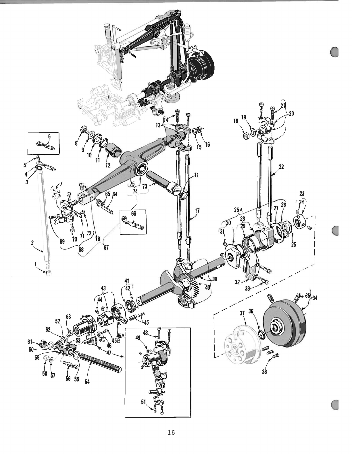
16
Page 27
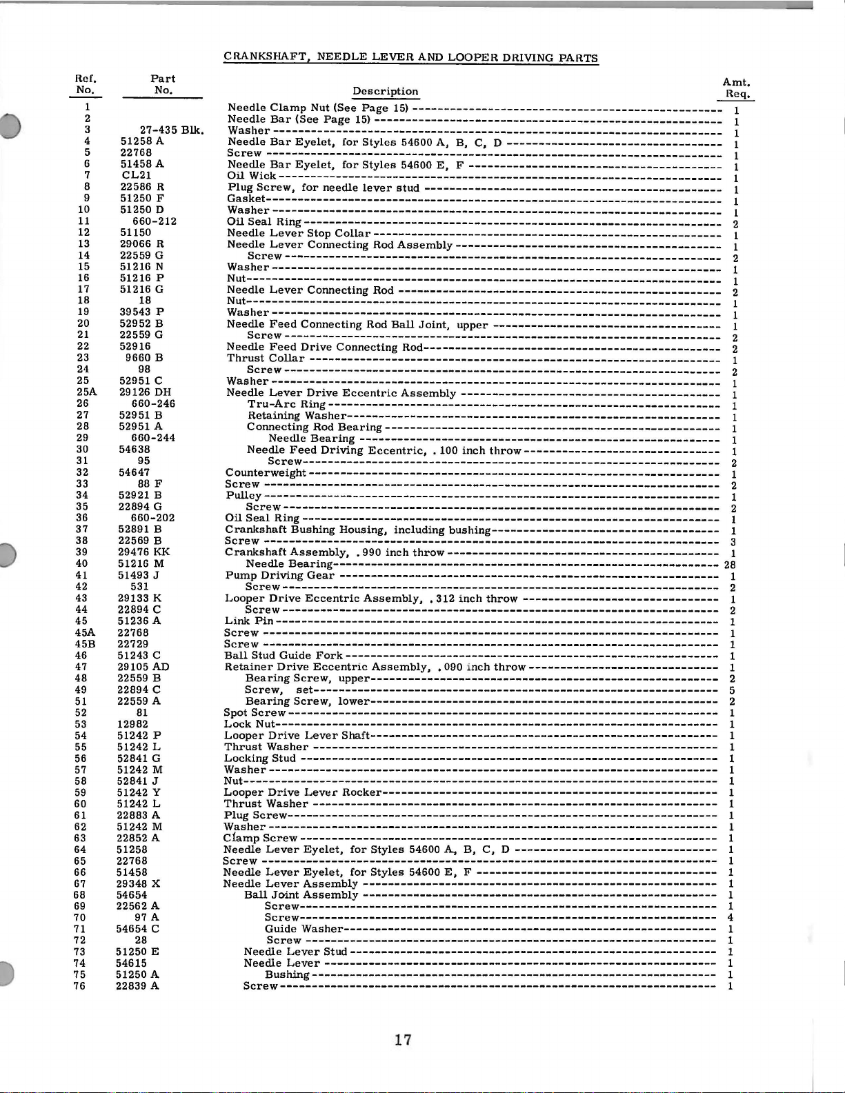
Ref.
No.
4
6
8
9
10
11
12
13
14
15
16
17
18
19
20
21
22
23
24
25
25A
26
27
28
29
30
31
32
33
34
35
36
37
38
39
40
41
42
43
44
45
45A
45B
46
47
48
49
51
52
53
54
55
56
57
58
59
60
61
62
63
64
65
66
67
68
69
70
71
72
73
74
75
76
1
2
3
5
7
Part
No.
27-435
51258 A
22768
A
51458
CL21
R
22586
51250 F
51250 D
660-212
51150
R
29066
22559 G
N
51216
51216 p
51216 G
18
39543 p
52952 B
22559 G
52916
9660 B
98
52951 c
29126
DH
660-246
B
52951
52951 A
660-244
54638
95
54647
88
F
52921 B
22894 G
660-202
52891 B
22569 B
29476
KK
51216 M
51493 J
531
K
29133
22894 c
51236 A
22768
22729
c
51243
29105 AD
22559 B
22894 c
22559 A
81
12982
p
51242
51242 L
52841 G
51242 M
52841 J
51242 y
51242 L
22883 A
51242 M
22852 A
51258
22768
51458
X
29348
54654
A
22562
97
A
54654 c
28
51250 E
54615
A
51250
22839 A
Blk.
CRANKSHAFT, NEEDLE LEVER
AND
LOOPER DIUVING PARTS
Description
Needle
Needle
VVasher----------------------------------------------------------------------Needle
Screw
Needle
Oil
Plug
Gasket------------------------------------------------------------------------
Clamp
Nut (See
Bar
(See
Bar
Eyelet,
-----------------------------------------------------------------------Bar
Eyelet,
Page
for
for
Page
15)
15)
Styles
Styles
-------------------------------------------------
------------------------------------------------------54600 A, B, C, D
54600
E, F ----------------------------------------
----------------------------------
VVick----------------------------------------------------------------------
Screw,
for
needle
lever
stud
-----------------------------------------------
VVasher-----------------------------------------------------------------------
Oil
Seal
Needle
Needle
Ring------------------------------------------------------------------
Lever
Stop
Lever
Collar-------------------------------------------------------
Connecting Rod
Assembly------------------------------------------
Screw---------------------------------------------------------------------
VVasher----------------------------------------------------------------------Nut--------------------------------------------------------------------------Needle
Nut---------------------------------------------------------------------------
Lever
Connecting Rod
---------------------------------------------------
VVasher----------------------------------------------------------------------Needle
Needle
Thrust
Feed
Screw---------------------------------------------------------------------
Connecting Rod
Feed
Drive
Connecting
Collar
Screw---------------------------------------------------------------------
-----------------------------------------------------------------
Ball
Joint,
upper
------------------------------------
Rod-----------------------------------------------
VVasher----------------------------------------------------------------------Needle
Counterweight----------------------------------------------------------------Screw
Pulley------------------------------------------------------------------------
Lever
Drive
Tru-Arc
Retaining
Ring--------------------------------------------------------------
VVasher-----------------------------------------------------------
Connecting Rod
Needle
Needle
Feed
Bearing
Driving
Eccentric
Bearing-----------------------------------------------------
Assembly
--------------------------------------------------------Eccentric,
-----------------------------------------
. 100
inch
throw-------------------------------
Screw------------------------------------------------------------------
------------------------------------------------------------------------
Screw---------------------------------------------------------------------
Oil
Seal
Crankshaft
Screw
Crankshaft
Pump
Looper
Link
Screw
Screw
Ball
Retainer
Spot
Lock
Looper
Thrust
Locking
Ring------------------------------------------------------------------
Bushing Housing, including
------------------------------------------------------------------------
Needle
Screw---------------------------------------------------------------------
Screw---------------------------------------------------------------------
Bearing-------------------------------------------------------------
Driving
Drive
Gear
Eccentric
Assembly,
• 990
inch
-----------------------------------------------------------Assembly,
bushing------------------------------------
throw-------------------------------------------
• 312
inch
throw
-------------------------------
Pin----------------------------------------------------------------------
------------------------------------------------------------------------
------------------------------------------------------------------------
Stud Guide
Bearing
Screw,
Bearing
Fork-----------------------------------------------------------
Drive
Eccentric
Screw,
set----------------------------------------------------------------
Screw,
Assembly,
• 090 inch
throw------------------------------
upper-------------------------------------------------------
lower-------------------------------------------------------
Screw--------------------------------------------------------------------
Nut----------------------------------------------------------------------
Drive
Lever
Shaft-------------------------------------------------------
VVasher
Stud------------------------------------------------------------------
----------------------------------------------------------------
VVasher----------------------------------------------------------------------Nut---------------------------------------------------------------------------
Looper
Thrust
Plug
Drive
Lever
VVasher
Screw--------------------------------------------------------------------
Rocker-----------------------------------------------------
----------------------------------------------------------------
VVasher----------------------------------------------------------------------CiampScrew------------------------------------------------------------------
Lever
Needle
Screw
Needle
Needle
Ball
Eyelet,
-----------------------------------------------------------------------Lever
Eyelet,
Lever
Assembly--------------------------------------------------------
Joint
Assembly
Screw------------------------------------------------------------------
for
Styles 54600 A. B, C, D
for
Styles
54600
E, F --------------------------------------
--------------------------------
--------------------------------------------------------
Screw------------------------------------------------------------------
VVasher-----------------------------------------------------------
Guide
Screw
Needle
Needle
-----------------------------------------------------------------
Lever
Stud----------------------------------------------------------
Lever
Bushing----------------------------------------------------------------
--------------------------------------------------------------
Screw---------------------------------------------------------------------
Amt.
Req.
1
1
1
1
1
1
1
1
1
1
2
1
1
2
1
1
2
1
1
1
2
2
1
2
1
1
1
1
1
1
1
2
1
2
1
2
1
1
3
1
28
1
2
1
2
1
1
1
1
1
2
5
2
1
1
1
1
1
1
1
1
1
1
1
1
1
1
1
1
1
1
4
1
1
1
1
1
1
17
Page 28

33
'tr
18
Page 29

NEEDLE
FEED
PARTS,
NEEDLE
BARS
AND
HEADS
Ref.
No.
1
2
3
4
5
6
7
8
9
10
11
12
13
14
15
16
16A
17
18
19
20
21
22
23
24
25
26
27
28
29
30
31
32
33
Part
No.
52849
51147
95
52951
54637
55235
6042
55235
51771
22758
54637
61985
43139
22593
54654
54637
61341
54617
51418-16
54617
54617
52849
52952
55235
6042
55235
22539
c
D
E
A
D
H
c
A
A
D
F
56
98
89
E-3-9
50
J-26
E-2-16
50 J
c
95
660-202
c
D
A
E
D
-16
Description
Needle
Rocker
VVasher-----------------------------------------
Needle
Feed
Shaft
Screw---------------------------------------
Feed
Rocker
Collar------------------------------
Drive
Shaft
Lever-------------------------
------------------------
Nut---·------------------------------------- 1
VVasher-Locking
Ferrule
Screw------------------------------------------
Link
Needle
Nut
Screw-----------------------------------------Ball
Needle
VVasher----------------------------------------Needle
Needle
Needle
Screw
Screw
Needle
Needle
Rocker
Screw---------------------------------------
Oil
Seal
Rocker
----------------------------------------
------------------------------------------Bar
---
----------------------------------------
Stud
Bar
Bar
Clamp
Holder
for
for
Bar
Needle
Bar
Needle
Shaft
Ring------------------------------------
Shaft
-------------------------~---------
Stud---------------------------------
Frame
Guide----------------------------------
Frame-------------------------------
for
Nut
Styles
Styles
for
Stop
for
Stop
Oil
Lever,
Pivot
Styles
for
for
Styles
54600
54600
No.
18
Pin------------------------------
No.
16
Pin------------------------------
Seal
Pin----------------------
54600
Styles
A,
A,
gauge
gauge
Collar----------------------
right------------------------
A,
54600
54600
B,
B,
Style
Styles
B,
C,
A,
E,
F--------------- 1
C,
D
----------------
C,
D
----------------
54600 E ---------
54600
D
-----------
B,
C,
E, F -----
D
-----
Screw--------------------------------------- 1
VVasher
-------------------------------------
Nut----------------------------------------- 1
Plug
Screw
-------------------------------------
Amt.
Req.
1
1
2
1
1
1
1
2
2
1
1
1
4
2
1
1
1
1
2
1
1
1
1
1
1
2
1
1
1
1
19
Page 30
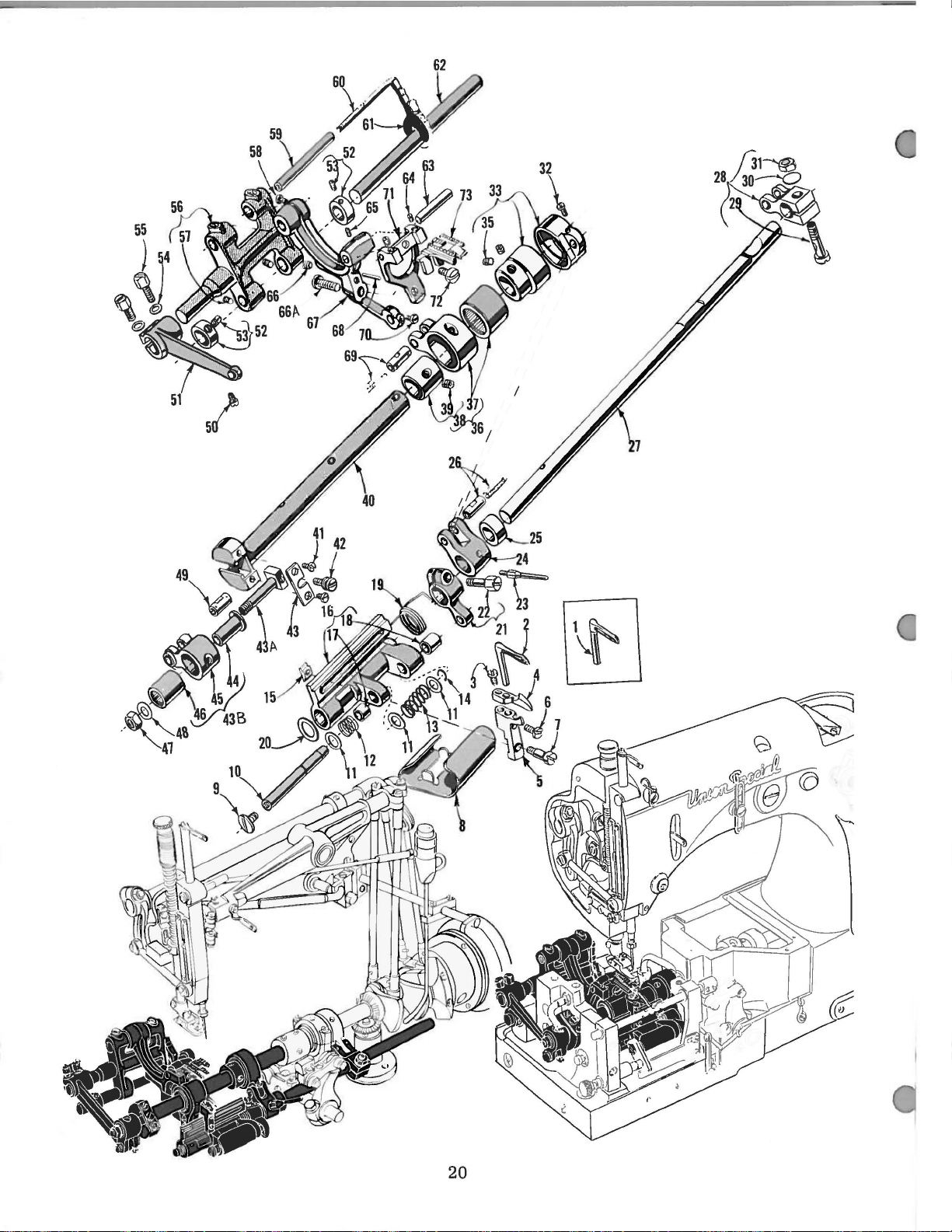
20
Page 31

He
f.
No.
1
2
3 22768
4 54625
5 54685
6
7
8 54244 M
9 22542
10
11
12
13
14
15
16
17
18
19
20
21
22
23
24
25
26
27
28
29
30
31
32
33 29133
35
36
37
38
39
40
41
42
43
43A 51236 G
43B
44 51236 F
45
46
47
48
49
50
51
52
53
54
55
56
57
58
59
60
61
62
63
64
65
66
66A
67
68
69
70
71
72
73
Part
No.
54208 A
54208
54208
22768
54625
54685
J87
J87
2255!!
2255!!
54244 D
6042 A
54244 H
39173 A
660-215
54285 c
54285 c
54244 p
54244 E
54244 F
54244 c
51242 L
54244 B
22519 c
54223 A
54245 A
54244 K
51236 A
51244 K
54244 A
55244 G
20
18
22768
22894 c
29476
54245
51406
22894 D
54622
22768
22795
51236 B
51236 E
51236 D
660-169
269
20
51054
77
51235 A
482
98
51235 G
22519 c
51235
98
22560 B
51134 c
51134 p
51134 R
8
54134 N
22560 B
22733
531
88
54234 B
667 B-20
51236 A
77
54234 c
HA61
J
J
D
D
J
KH
c
F
D
MAIN
SHAFT,
Looper,
Loopct·, for
Looper,
Screw,
Screw,
Looper
Looper
Looper
Looper
Screw,
Screw,
Screw,
Screw,
Looper
Screw---------------------------------------------------------------------------------
Looper
VVasher
Throw-out
Looper
Hetaining
Nut,
Nut,
Looper
Looper
Thrust
Looper
Looper
Looper
Spacing
Link
Looper
Looper
Screw--------------------------------------------------------------------------------Take-up
Feed
MainShaft----------------------------------------------------------------------------Screw--------------------------------------------------------------------------------Stitch
Feed
Feed
Feed
Nut,
VVasher
Feed
Screw--------------------------------------------------------------------------------Feed
Feed
VVasher
Screw---------------------------------------------------------------------------------
Feed
Screw---------------------------------------------------------------------------------
Feed
Lubricating
Lubricating
Feed
Pin----------------------------------------------------------------------------------Screw--------------------------------------------------------------------------------Screw--------------------------------------------------------------------------------Screw--------------------------------------------------------------------------------Screw,
Feed
Dowel
Link
Screw---------------------------------------------------------------------------------
Feed
Screw---------------------------------------------------------------------------------
Feed
for
Style 54600
Styles
for
Styles
for
Styles
for
Styles
Holder
Holder
Holder,
Holder,
for
for
for
for
Holder
Holder
Frame
for
for
Holder
Bush1ng,
Bushing,
Throw-out
VVasher-------------------------------------------------------------------------
Holder
Screw
Thread
Thread
Collar-------------------------------------------------------------------------
Pin
Rocker
Travel
Locking
\Nasher---------------------------------------------------------------------------Nut,
Screw,
Lift
Eccentric
Eccentric,
Screw--------------------------------------------------------------------------
Regulating
Crank
Crank
Crank
Feed
Feed
Needle
left
-------------------------------------------------------------------------------
Crank
Rocker
Rocker
Screw
-------------------------------------------------------------------------------
Rocker---------------------------------------------------------------------------
Screw
Bar
Rocker
for
Bar------------------------------------------------------------------------------
Pin,
Pin
Bar
Dog(See
Needle
Needle
Styles
Styles
Styles
Styles
Frame
Frame
------------------------------------------------------------------------------Fork
Locking
Ring-------------------------------------------------------------------------
Styles
54600 A,
Styles
54600
Frame
left-----------------------------------------------------------------------
right----------------------------------------------------------------------
Frame
----------------------------------------------------------------------------Take-up-----------------------------------------------------------------
Take-up
-----------------------------------------------------------------------------Shaft--------------------------------------------------------------------
Drive
Stud-----------------------------------------------------------------------
for
locking
Drive
Eccentric
set-------------------------------------------------------------------------
Eccentric
Bearing------------------------------------------------------------------
• 062 inch
Stud
Stud-----------------------------------------------------------------------
LinkAssemb1y--------------------------------------------------------------
Crank
Link
Crank
Link--------------------------------------------------------------------
Bearing---------------------------------------------------------------------
thread------------------------------------------------------------------------
Link
Arm---------------------------------------------------------------------Shaft
-----------------------------------------------------------------------------
-----------------------------------------------------------------------------
Shaft-------------------------------------------------------------------------
Felt
Felt
Shaft----------------------------------------------------------------------
feed
bar
for
feed
-----------------------------------------------------------------------------Tilting
Page
FEED
DRIVING
Description
B--------------------------------------------------------------54600 A,
54600
54600 A, B, C,
54600
for
Styles
for
Styles
54600 A, B,
54600
54600 A, B,
54600
Pressure
Spring
Link---------------------------------------------------------------
stud----------------------------------------------------------------
Assembly-----------------------------------------------------------
Stud-------------------------------------------------------------------
Cap-------------------------------------------------------------------
Ferrule------------------------------------------------------------
Pin-------------------------------------------------------------------
Collar
----------------------------------------------------------------------Guard
-------------------------------------------------------------------bar-----------------------------------------------------------------
Extension--------------------------------------------------------------
21)
C,
D--------------------------------------------------------
E,
F-----------------------------------------------------------
E,
F-----------------------------------------------------------Guard,
Guard,
Thread
Locking
E, F --------------------------------------------------------------
------------------------------------------------------------------
Driving
for
for
54600 A, B, C, D
54600
C,
E,
F------------------------------------------------------------
C,
E,
F------------------------------------------------------------
Shield
Pin-------------------------------------------------------
Spring
Pin
Spring
B, C, D --------------------------------------------------------
--------------------------------------------------------------Arm
Driving
Assembly,
throw
----------------------------------------------------------
---------------------------------------------------------------
-----------------------------------------------------------------
-----------------------------------------------------------------
AND
LOOPER DRIVING PAHTS
D------------------------------------------------------
Styles
54600 A, B, C, D
Styles
54600
E, F ---------------------------------------
E, F ----------------------------------------------------
D-----------------------------------------------------D------------------------------------------------------
-----------------------------------------------------
--------------------------------------------------------
-------------------------------------------------------
------------------------------------------------------
Link-----------------------------------------------------
• 312 inch
----------------------------------------------
throw---------------------------------------
---------------------------------
21
Amt.
Req.
1
1
2
1
2
1
2
1
2
1
2
1
2
1
1
1
3
1
1
1
1
2
1
1
1
1
1
1
1
1
1
1
1
1
1
1
1
1
1
1
2
1
1
1
1
1
2
1
1
1
1
1
1
1
1
1
1
1
1
2
1
2
2
1
2
1
1
1
1
1
1
2
1
1
1
1
1
1
1
1
1
1
Page 32
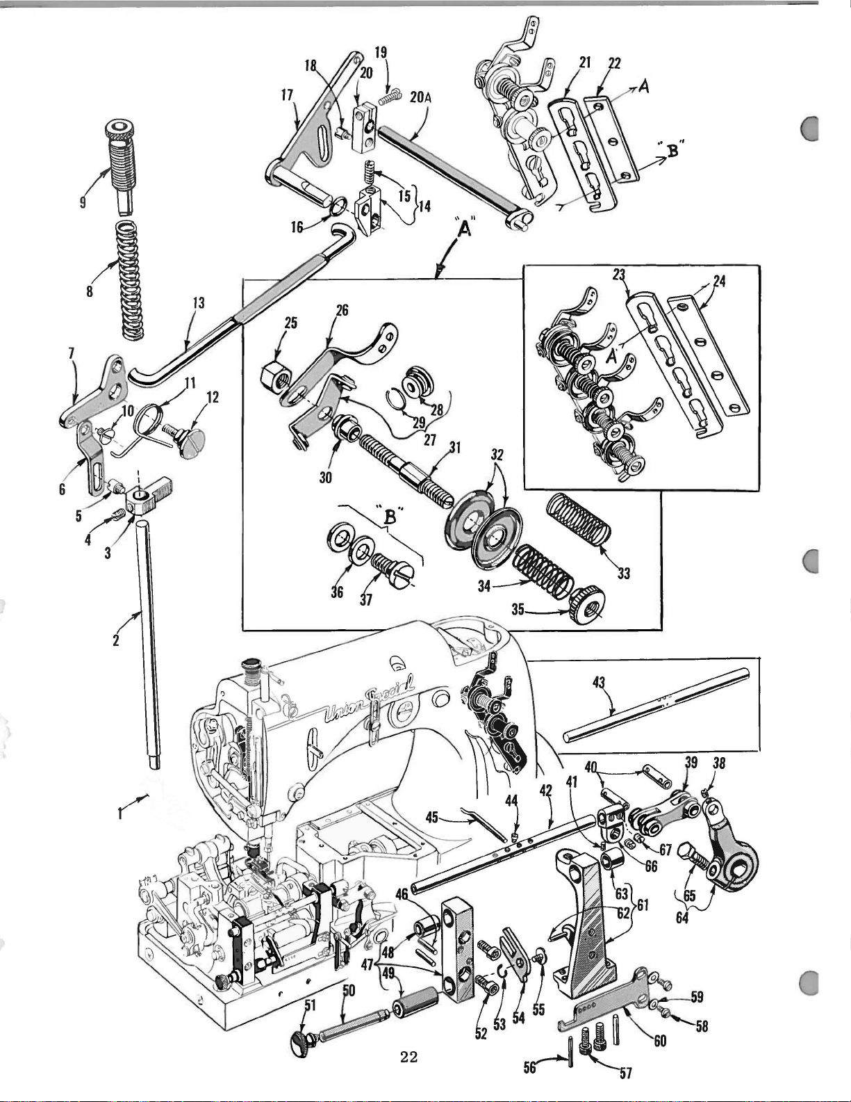
Page 33
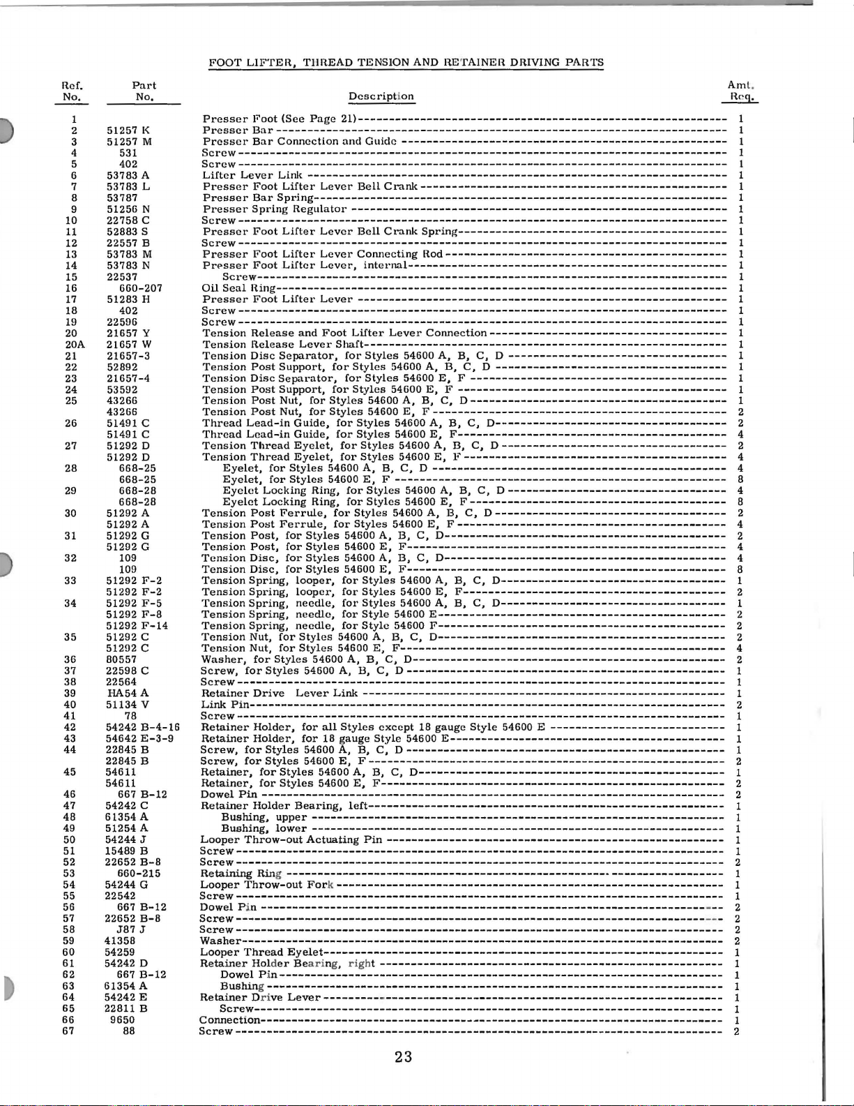
Ref.
No. No.
1
2
3
4 531
5
6
7
8
9
10
11
12
13
14
15
16
17
18
19
20
20A
21
22
23
24
25
26
27
28
29
30
31
32
33
34
35
36
37
38
39
40
41
42
43
44
45
46
47
48
49
50
51
52
53
54
55
56
57
58
59
60
61
62
63
64
65
66
67
Part
51257
51257
402
53783
53783
53787
51256
22758
52883
22557
53783
53783
22537
660-207
51283
402
22596
21657
21657
21657-3
52892
21657-4
53592
43266
43266
51491
51491
51292
51292
668-25
668-25
668-28
668-28
51292
51292
51292
51292
109
109
51292
51292
51292
51292
51292
51292
51292
80557
22598
22564
HA54A
51134
78
54242
54642
22845
22845
54611
54611
667
54242
61354
51254
54244
15489
22652
660-215
54244
22542
667
22652
J87
41358
54259
54242
667
61354
54242
22811
9650
88
K
M
A
L
N
c
s
B
M
N
H
y
w
c
c
D
D
A
A
G
G
F-2
F-2
F-5
F-8
F-14
c
c
c
v
B-4-16
E-3-9
B
B
B-12
c
A
A
J
B
B-8
G
B-12
B-8
J
D
B-12
A
E
B
FOOT
LIFTER,
Presser
PresscrBar------------------------------------------------------------------------
Press
Screw-----------------------------------------------------------------------------Screw------------------------------------------------------------------------------
Lifter
Presser
Presser
Presser
Screw------------------------------------------------------------------------------
Presser
Screw------------------------------------------------------------------------------
Presser
Prt>sser
Oil
Presser
Screw------------------------------------------------------------------------------
Screw------------------------------------------------------------------------------
Tension
Tension
Tension
Tension
Tension
Tension
Tension
Tension
Thread
Thread
Tension
Tension
Tension
Tension
Tension
Tension
Tension
Tension
Tension
Tension
Tension
Tension
Tension
Tension
Tension
Washer,
Screw,
Screw------------------------------------------------------------------------------
Retainer
Link
Screw------------------------------------------------------------------------------
Retainer
Retainer
Screw,
Screw,
Retainer,
Retainer,
Dowel
Retainer
Looper
Screw------------------------------------------------------------------------------
Screw------------------------------------------------------------------------------
Retaining
Looper
Screw------------------------------------------------------------------------------
Dowel
Screw--------------------------------------------------------------------------Screw------------------------------------------------------------------------------
Washer----------------------------------------------------------------------------Looper
Retainer
Retainer Dri
Connection------------------------------------Screw---------------------------
Foot
e r
Bar
Lever
Foot
Bar
Spring
Foot
Foot
Foot
Screw--------------------------------------------------------------------------Seal
lling------------------------------------------------------------------------
Foot
Release
Release
Disc
Post
Disc
Post
Post
Post
Lead-in
Lead-in
Thread
Thread
Eyelet,
Eyelet,
Eyelet
Eyelet
Post
Post
Post,
Post,
Disc,
Disc,
Spring,
Spring,
Spring,
Spring,
Spring,
Nut,
Nut,
for
for
Drive
Pin----------------------------------------------------------------------------
Holder,
Holder,
for
for
for
for
Pin
Holder
Bushing,
Bushing,
Throw-out
Ring----------------------------------------------------------------------
Throw-out
P in
Thread
Holder Beari
Dowel
P i
Bushing------------------------------------------------------------------------Screw---------------------------------------------------------------------------
TIIREAD
(See
Page
Connection
Link
-------------------------------------------------------------------
Lifter
Spring--------------------------------------------------------
Regulator
Lifter
Lifter
Lifter
Liftet·
and
Lever
Separator,
Support,
Separator,
Support,
Nut,
for
Nut,
for
Guide,
Guide,
Eyelet,
Eyelet,
for
Styles
for
Styles
Locking
Locking
Styles
Styles
Styles
--------------------------------------------------------------------------
-----------------------------------------------------------------------
Ring,
Ring,
Ferrule,
Ferrule,
for
Styles
for
Styles
for
Styles
for
Styles
looper,
looper,
needle,
needle,
needle,
for
Styles
for
Styles
Styles
54600
54600
Lever
for
for
54600
54600
Styles
Styles
Bearing,
upper
------------------------------------------------------------------
lower
------------------------------------------------------------------
Actuating
Fork--------------------------------------------------------------
Eyelet---------------------------------------------------------------n----------------------------------------------------------------------ve
Lever---------
TENSION
Description
21)----------------------------------------------------------and
Guide
Lever
Bell
---------------------------------------------
Lever
Bell
Lever
Connecting
Lever,
Lever
Foot
all
54600
54600
internal---------------------------------------------------
-----------------------------------------------------------
Lifter
Shaft----------------------------------------------------------
for
Styles
for
Styles
for
Styles
for
Styles
Styles
54600
Styles
54600
for
Styles
for
Styles
for
Styles
for
Styles
54600
A,
54600
E, F -----------------------------------------------------
for
Styles
for
Styles
for
Styl
for
Styles
54600
54600
54600
54600
for
Styles
for
Styles
for
Styles
for
Style
for
Style
54600
54600
A,
B,
A,
B,
Link----------------------------------------------------------
Styles
18
gauge
A,
B, C, D ---------------------------------------------------
E, F ---------------------------------------------------------
A,
E,
left---------------------------------------------------------
Pin
ng,
right -------------------------------------------------------
AND
RETAINER
----------------------------------------------------
Crank-------------------------------------------------
Crank
Spring-------------------------------------------
Rod---------------------------------------------
Lever
Connection--------------------------------------
54600
A,
54600
54600
54600
A,
E, F ----------------------------------------------54600
54600
54600
54600
B,
C, D -----------------------------------------------
54600
54600
es
54600
54600
A,
B,
E,
F---------------------------------------------------
A,
B,
E,
F---------------------------------------------------
54600
54600
54600
54600
54600
A,
B,
C,
E,
F----------------------------------------------------
C,
D--------------------------------------------------
C, D ---------------------------------------------------
except
Style
54600
B, C,
D-------------------------------------------------
F-------------------------------------------------------
------------------------------------------------------
-
------------------------------------------------------
-
--------------------------------------------------
B,
A,
B, C, D -------------------------------------
E, F -----------------------------------------
E, F -------------------------------------------
B, C, D -----------------------------------------
A,
B, C,
E,
F-------------------------------------------
A,
B,
E, F ------------------------------------------
A,
B,
E, F -----------------------------------------
A,
B,
C, D -------------------------------------
E,
F
-------------------------------------------
C,
D---------------------------------------------
C,
D---------------------------------------------
A,
B,
E,
F------------------------------------------
A,
B, C,
E----------------------------------------------
F---------------------------------------------D----------------------------------------------
18
gauge
E--------------------------------------------
DRIVING
C, D -----------
D-------------------------------------
C, D ------------------------------------
C, D -----------------------------------
C,
D-----------------------------------D------------------------------------
Style
54600 E ----------------------------
-
------------------------------------
PARTS
-
-----------------------
-
---------
-
--------------
Aml
.
~
1
1
1
1
1
1
1
1
1
1
1
1
1
1
1
1
1
1
1
1
1
1
1
1
1
1
2
2
4
2
4
4
8
4
8
2
4
2
4
4
8
1
2
1
2
2
2
4
2
1
1
1
2
1
1
1
1
2
1
2
2
1
1
1
1
1
2
1
1
1
2
-
--
--
-
2
2
2
1
1
1
1
1
1
1
2
23
Page 34
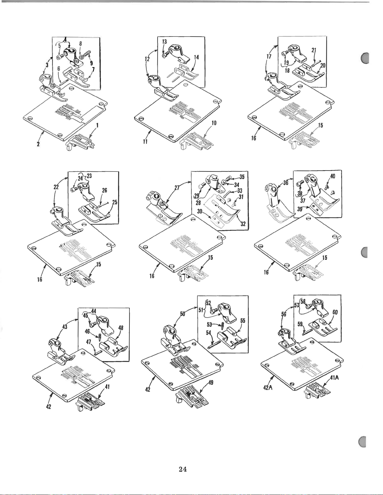
24
Page 35
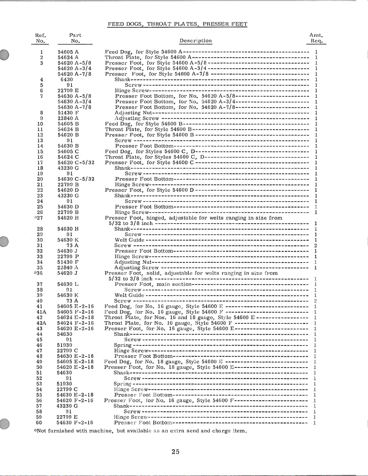
FEED
DOGS,
THROAT
PLATES,
PRESSER
FEET
Ref.
No.
54605
1
54624
2
54620
3
54620
54620
4
5
6
7
8
9
10
11
12
13
14
15
16
17
18
19 91
20
21
22
23
24
25
26 227!J9 B
>:
•27
28
2!J
30
31
32
33
34
35
::•36
37
38
39
40
41
41A
42
42A
43
44
45
46
47
48
49
50
51
52 91
53
54
55
56
57
58
59
60
::•Not
6430
91
227!J9 E
54630
54630
54630
51430
22840
54605
54624
54620
91
54630
54605
54624
54620
43230
54630
2279!J B
54620
43230
91
54630
54620
54630
91
54630
73 A
54630
22799
51430
22840
54620
54630
fl1
54630
73 A
54605
54605
54624
54624
54620
54630
!J1
51930
22799
54630
54605
54620
54630
51930
22799
54630
54620
43230
91
22799
54630
furnished
Part
No.
A
A
A-518
A-31
A-7
A-518
A-31
A-7
F
A
B
B
B
B
c
c
C-5132
G
C-5132
D
G
D
H
H
K
J
p
F
A
J
L
K
E-2-16
F-2-16
E-2-18
F-2-16
E-2-16
c
E-2-16
E-2-18
E-2-18
c
E-2-18
F-2-16
G
E
F-2-16
with
4
I B
4
I 8
machine,
Description
Feed
Dog,
for
Style
54600
Throat
Presser
Presser
Presser
Feed
Throat
Presse
Feed
Throat
Presser
Presser
Presser
Presser
Feed
F
Throat
Throat
Presser
F
Presser
P ress er Foot, f
Plate,
Shank----------------------------------------------------------
Screw------------------------------------------------------
Hinge
Presser
Presser
Presser
Adjusting
A
djusting Screw------------------------------------------------
Dog,
Plate,
Screw
Presser
Dog,
Plate,
Shank----------------------------------------------------------
Screw------------------------------------------------------
Presser
Hinge
Shank----------------------------------------------------------
Screw-----------------------------------------------------Presser
Hinge
5132
to
Shank----------------------------------------------------------
Screw-----------------------------------------------------\Velt
Screw
Presser
Hinge
Adjusting
Adjusting
5132
to
Presser
Screw-----------------------------------------------------Welt
Screw
Dog, for
eed
Dog, for
Plate,
Plate,
Shank----------------------------------------------------------
Screw------------------------------------------------------
Spring---------------------------------------------------------
Hi
nge
Presser
eed
Dog,
Shank----------------------------------------------------------
Screw-----------------------------------------------------Spring
Hi
ng e Scre
Pres
Shank----------------------------------------------------------
Screw-----------------------------------------------------Hinge Scr ew
Pre
s s
but
available as
for
Foot,
Foot,
F'
oot,
Screw----------------------------------------------------
for
Foot,
--------------------------------------------------------for
Foot,
Screw----------------------------------------------------
Foot,
Screw----------------------------------------------------
Foot,
318
Guide-----------------------------------------------------
---------------------------------------------------------
Screw----------------------------------------------------
Foot,
318 inch
Guide-----------------------------------------------------
---------------------------------------------------------
Foot,
Sere w----------------------------------------------------
for
Foot,
---------------------------------------------------------
se r Foot Bottoln--------------------------------------------
er Foot Bottom--------------------------------------------
Style
for
Style
for
Style
for
Style
l•
oot
Bottom,
Foot
Bottom,
Foot
Bottom,
Nut---------------------------------------------------
Style
for
Style
for
Style
Foot
Botton1--------------------------------------------
Styles
for
Styles
for
Style
Foot
Bottom--------------------------------------------
for
Style
Foot
Bottom--------------------------------------------
hinged,
inch--------------------------------------------------
Foot
Bottom--------------------------------------------
Nut---------------------------------------------------
Screw------------------------------------------------
solid,
--------------------------------------------------
Foot,
main
No.
16
No.
16
for
Nos.
for
No.
for
No.
Foot
Bottom--------------------------------------------
No.
18
for
No.
w----------------------------------------------------
or
No.
----------------------------------------------------
A-----------------------------------------
54600
A--------------------------------------
54600
A-51 8 ---------------------------------
54600
A-31
54600
for
for
for
54600
B-----------------------------------------
54600
54600 B -------------------------------------
54600
C,
54600
54600 C -------------------------------------
54600 D -------------------------------------
adjustable
adJustable
section--------------------------------------
gauge,
gauge,
16
and
16
gauge,
16
gauge,
gauge,
18
gauge,
16 g
auge,
an ext
ra
4---------------------------------
A-718
No.
No.
B--------------------------------------
D------------------------------------C,
Style
Style
18
Style
send
--------------------------------
54620
o. 54620
D----------------------------------
for
for
gauge, Sty
Style
Style
Style
Style
A-518------------------------
A-31
54620
A-718------------------------
welts
welts
ranging
54600 E ---------------------------
54600 F ---------------------------
54600 F ------------------------
54600
54600 E ---------------------------
54600 E------------------------
54600
and
charge item
4------------------------
ranging
le
E------------------------
F------------------------
in
size
from
in size from
54600 E -----------------
.
Amt.
Req.
1
1
1
1
1
1
1
1
1
1
1
1
1
1
1
1
1
1
1
1
1
1
1
1
1
1
1
1
1
1
1
1
1
1
2
1
1
1
1
1
1
1
1
2
1
1
1
1
1
1
1
1
1
1
1
1
1
1
1
1
1
1
1
1
1
1
25
Page 36

16
15
1
4
33
41
42
I
I
I
I
I
26
Page 37

ATTACHMENTS
AND
TAPE
REEL
Ref.
No.
1
2
3
4
5
6
7
8
9
10
11
12
13
14
15
16
17
17A
18
19
20
21
22
23
24
25
26
27
28
29
30
31
32
33
34
35
36
37
38
39
40
41
42
43
44
45
23322
23322
23437
23437
357
54603
12957 E
22726
90
25 c
25
24
22585
23215
23215
23215
90
23437
22735
12957
23437
23437
22798
23437
23437
25
23405
22565
22564
22711
54603
23437
23422
23422
23422
23421
23421
23421
23421
23421
28
23439
22585
25 c
23425
660-237
54464
54264
54264
12986
21169
161
88
21169
Part
No.
AK
AJ
s
T
A
A
BJ-5/8
BJ-3/4
BJ
-7/8
L
E
c
R
M
N
c
s
c
D
p
V-1/32
U-1/16
U-3/32
V-16-1/32
U-16-1/16
U-16-3/32
U-18-1/16
U-18-3/32
A
c
v
B
c
B
E
F
Description
Binder
Screw,
Screw,
Edge
Screw,
Binder,
Binder,
Binder,
Screw,
Folder
Lower
Lower
Nos.
Lower
Nos.
Upper
Style
Upper
Style
Upper
Style
Upper
Style
Upper
Style
Screw
Tape
Screw
Screw
Washer
Spring
Folder
Spring-----------------------------------------------Spring,
Screw
Binding
Binding
Binding
and
Welt
Guide
Binder,
Base
Adaptor
Screw--------------------------------------------Welt
Washer-------------------------------------------Screw-------------------------------Screw,
Guide,
5/16
3/8
inch
7/16
Screw--------------------------------------------Washer-------------------------------------------Binder
Edge
Screw---------------------------------------------
Folder
Hemmer
Screw---------------------------------------------
Folder,
capacity,
Stop
Stop
Screw---------------------------------------------
Edge
Edge
gauge
Guide,
Screw---------------------------------------------
uses
Block
Guide-----------------------------------------
for
for
for
uses
inch
uses
uses
inch
for
Assembly,
Guide
Screw----------------------------------------Screw-----------------------------------------
Guide
Guide
Scroll
on
Scroll
16
Scroll
16
Scroll,
54600 E ----------------------------------------
Scroll,
54600 E ----------------------------------------
Scroll,
54600 E ----------------------------------------
Scroll,
54600 E ----------------------------------------
Scroll,
54600 E ----------------------------------------
------------------------------------------------
------------------------------------------------
------------------------------------------------
Plate------------------------------------------
Lock
Mounting
with
------------------------------------------------
Holder
Holder
Holder
----------------------------------------
Block--------------------------------------
for
No. 23322
No.
23322
No.
24
for
Styles
No.
23437 L --------------------------------
5/8
wide,
3/4
wide,
Style
and
and
for
7/8
wide,
No.
23215
Bracket-------------------------------------
Spring----------------------------------
Mounting
Swing-out
for
turning
1/4
---------------------------------------Swing-out
and
54600 E
and
18
and
18
gauge
1/32
1/16
3/32
1/16
3/32
for
Style
Fastener
Swinging
finger
Disc,
Stop
Base,
Assembly,
3/4
inch
strip
AJ
AK
-------------------------------
------------------------------------54600
inch
selvage
for
Style
inch
Style
inch
for
for
Base-------------------------------
inch
Base,
Base,
gauge
Base,
inch
inch
inch
inch
inch
projection---------------------------
Collar,
54600 A ----------------------
selvage
54600 A -----------------------
selvage
Style
54600 A ----------------------
BJ
-------------------------------
Style
54600 A ---------------------
Lever
material
fold-----------------------------
Lever-------------------------
1/32
-------------------------------1/16
on
Style
3/32
on
Style
capacity,
capacity,
capacity,
capacity,
capacity,
54600
A---------------------------
---------------------------------Bracket-----------------------
for
Style
for
for
Style
for
and
finishes
----------------------------
B,
D-----------------------
edge
binding
edge
binding
edge
binding
--------------------------downward,
inch
capacity,
inch
capacity,
54600 E ------------------
inch
capacity,
54600 E ------------------
for
for
for
for
for
54600
A-------------------
Style
54600 A
Style
No. 16
No.
No.
No.
No.
54600
------------------
54600
and
and
16
16
18
18
A-------------
3/8
inch
..
------------
finishes
and
finishes
finishes
1/16
for
No. 16
for
for
gauge
gauge
gauge
gauge
gauge
F--------
inch
wide--
on
on
on
on
on
Amt.
Req.
1
1
1
1
2
1
1
1
2
2
2
1
2
1
1
1
2
1
3
3
1
1
1
1
1
2
1
1
1
1
1
1
1
1
1
1
1
1
1
1
1
1
1
2
1
1
1
1
1
2
1
1
1
1
27
Page 38

~
31
~
3{~
A
28
Page 39

THREAD
STAND
AND
ACCESSORIES
Ref.
No
1
2
3
4
5
6
7
8
9
10
11
12
13
14
15
16
17
18
19
20
21
22
23
24
25
26
27
28
29
30
31
32
33
34
35
36
Part
.
No.
21101
21101
21114
22651
22810
21114
22651
21114
652-16
21104
21104
21114
21114
22651
21114
21114
22651
21114
21114
21114
21114
21104
21104
21114
21114
258
258
21114
21114
652-16
652-16
21114
21114
21114
21114
21114
21114
421
116
21227
21201
51493
660-264
21388
118B
H-2
H-4
A
CD-3
T
CD-4
u
H
B-24
D-2
D-4
CD-5
H-2
H-4
CD-4
L
L
M
M
v
v
w
w
A
A
S-2
S-4
M
M
L
L
D-28
BT
BC
Thread
Thread
Stand.
Stand,
Thread
Screw-------------------------------------
Screw
Lead
Eyelet
complete.
complete.
Stand
----------------------------------------
Screw-------------------------------------
Lead
Washer---------------------------------------
Nut-------------------------------------------
Thread
Spool
Spool
Eyelet
Eyelet
Eyelet
Stand
Seat
Support,
Seat
Support,
Screw-------------------------------------
Support.
Support.
Screw-------------------------------------
Felt
Felt
Spool
Spool
Nut,
Nut,
Spool
Spool
Washer,
Washer,
Lead
Lead
Treadle
Wrench,
Needle
Screw
over-all
Lifter
Hook
Wrench,
Thread
Eyelet,
Eyelet,
Eyelet
Eyelet
Pad,
Pad,
Pin,
Pin,
for
for
Seat
Seat
Eyelet,
Eyelet.
Eyelet
Eyelet
Eyelet.
Eyelet.
Chain,
for
Gauge-------------------------------------
Driver,
7
Link--------------------------------------- 1
-----------------------------------------
single
Tweezers
for
for
Locking
Locking
for
for
for
for
No.
No.
Disc,
Disc,
for
for
Locking
Locking
for
for
28
Styles
9/64
5/8
inches,
end,
Description
for
Styles
for
Styles
Base-----------------------------
Socket
Ball
Rod------------------------------
No.
No.
No.
No.
21101 H ...
21101
No.
No.
for
for
---------------------------------
Ball
------------------------
Split
for
for
No.
No.
for
for
21101
21101
No.
No.
21114
21114
inches
54600
inch
3/8
Socket--------------------
for
No.
for
No.
No.
21101
No.
21101
21114
21114
Ring,
Ring.
21101
21101
21101
21101
H-4-------------------------
No.
No.
Ring,
Ring,
for
inch
H-2-------------------
H-4------------------for
for
H-2
H-4
H-2
H-4
2-------------------------
21101
21101
H-2
H-4
21101
21101
for
for
S-2
-----------------------
S-4
-----------------------
long----------------------
A,
B,
round
Styles
opening
54600
54600
21101
21101
No.
No.
--------------------
--------------------
---------------------
--------------------H-2
H-4
No.
No.
c. D
blade,
H-2
H-4
H-2--------------H-4---------------
21114
21114
-------------------
-------------------
H-2
--------------
H-4
-----------------
----------------21114
21114
--------------length
54600
---------------
A,
B,
c.
E,
F-------
-----------
-----------
H-2
------
H-4
------
--------------
S-2------S-4-------
E,
F--------
D---
Amt.
Req.
1
1
1
1
1
1
2
2
1
1
1
1
1
2
1
1
2
2
4
2
4
2
4
2
4
4
8
2
4
2
4
1
1
2
4
2
4
1
1
1
1
1
1
1
29
Page 40
NUMERICAL
INDEX
OF
PARTS
Part
No.
8
•.•••••••••••
18
•••••••••••••
20
•••••••••••••
CL21
•••••••••••••
24
•••••••••••••
25
•••••••••••••
25
c
...........
27-435
28
50-294
50-648
50-789
50 J
52 A •••••••.•••
HA54 A •••••••••••
56
HA61 D •••••••••••
73
77
78
80
81
J87J
88
88F
89
90
91
93
95
97
98
98
109
116
118B
158B
161
258A
269
294
357
402
421 D •••••••••••
482
531
539
643-127
643-263
652-16
660-136
660-169
660-202
660-207
660-212
660-215
660-237
660-244
660-246
660-264
666-65
666-99
Blk
•••••••••••••
•••••.•.•..•
•••••••••••••
A
•••••••••••••
•••••••••••••
•••••••••••••
•••••••••••••
••••••••••••
•••••••••••••
•••••••••••••
•••••••••••••
•••••••••••••
•••••••••••••
•••••••••••••
A
•••••••••••••
A
•••••••••••••
•••••••••••••
•••••••••••••
••..•••.•.•••
•.••••••...•.
•••.••..•••.•
.............
•••••••••••••
•••••••••••••
•••••••••••••
••••••
Blk
••••••
Blk
••••••
Blk
••••••
•••••••••••
•••••••••••
•••••••••••
•••••••••••
•••••••••••
•••••••••••
•••••••••••
Blk
••••••
Blk
••••••
••••••••••
.........
•••••••••
•••••••••
•••••••••
•••••••••
•••••••••
•••••••••
•••••••••
•••••••••
•••••••••
••••••••••
••••••••••
Page
No.
21
17,21
13,
17
27
27
27
17
17,27
15
15
13
19
13
23
19
21
25
21
23
13
17
21,23
23,
17,21
19
13, 15,
25
13
13,
17
17,19,21
13
23
29
29
13
27
15,29
21
13
27
23
29
21
15,17,21,
23
13
15
15
29
15
21
17'
23
17
21,
27
17
17
29
15
15
15,21
27
17,19
19
23
27
Part
No.
666-111.
666-114
666-118
666-179
666-201.
666-209
666-217
666-218
667 B •••••••
668-25
668-28
668-29
719
•••••••••
6042 A •••••••
6430
•••••••••
9650
•••••••••
9660 B •••••••
12934 A •••••••
12957
E
12982
12986 B .......
15489 B .......
21101 H •••••••
21104 B •••••••
21104 H •••••••
21104
21114
21114 A •••••••
21114 D •••••••
21114 H .......
21114 L •••••••
21114 M ......
21114
21114 T .......
21114
21114
21169
21169 F .......
21201.
21212
21227
B21375
21388
21657
21657
21657
21657
22513
22517 F •••••••
22519
22524
22528
22537
22539 D •••••••
22539 H •••••••
22541 B •••••••
22542
22548
22557 B •••••••
22559 A •••••••
22559 B •••••••
22559 D •••••••
22559 G •••••••
•••••••
•••••••••
v
.......
•••••••••
s
.......
u
.......
w
......
E
......
••••••••
•••••••••
BT
AH
•••••••••
•••••••••
w
......
x
.......
Y
.......
•••••••••
c
.......
•••••••••
c
.......
•••••••••
•••••••••
•••••••••
••••
•••••
•••••
•••••
••••
•••••
•••••
•••••
••••••
••••••
••••••
•••••
•••••
Page
No.
15
15
15
15
15
15
15
15
21,
23
13,23
13
13
19,21
25
23
17
13
27
17
27
23
29
29
29
29
29
29
29
29
29
29
29
29
29
29
27
27
29
15
29
13
29
23
23
15
23
13
13
21
13
13
23
19
15
13
21,
13
23
17
17
21
17
23
23
Part
No.
22560 B ••••••
22562A
22564
22564 D ••••••
22565
22569 B ••••••
22569
22571 A ......
22574
22585 A ••••••
22585
22586
22593
22596
22598
22645 H ••••••
22651
22652 B ••••••
22706 A ••••••
22711.
22726
22729
22729 A ......
22729 B ......
22733
22733 B ••••••
22735
22758
22758 H ••••••
22768
22784 F ......
22795
22798
22799 B ••••••
22799
22799
22799
22810
22811 B ••••••
22823 A ••••••
22823 B ••••••
22839
22839 A ••••••
22839
22840 A ••••••
22845 B ••••••
22848
22852 A ••••••
22883 A ••••••
22889 A ••••••
22889
22889 D ••••••
22891 A ••••••
22894
22894 D ••••••
22894 G ••••••
23215
23322
23322
23405
23421
23421
23422
••••••
••••••••
c
......
c
......
••••••••
c
......
R
••••••
••••••••
••••••••
c
......
CD
•••••
.......
••••••••
••••••••
••••••••
••••••••
c
......
........
••••••••
••••••••
c
......
E
••••••
p
•.••••
••••••••
••••••••
c
......
••••••••
c
......
c
......
BJ
•••••
AJ
•••••
AK
•••••
s
......
u
......
v
......
u
......
Page
No.
21
13,17
23
27
27
15,
13,
15
13
13,
13,
17
19
23
23
15
29
23
15
27
27
17
15
15
21
13
27
23
19
17,
13
21
27
25
25
25
25
29
23
15
15
13
17
13
25
23
13
17
17
13
15
15
13
17,21
21
17
27
27
27
27
27
27
27
17
15
27
27
21
Part
No.
23422
v
23425
23437
23437 L ••••••
23437 M ••••••
23437
23437
23437
23437
23437 T ••••••
23439 A ••••••
29066
29105
29126
29133 J ......
29133K
29348X
29476
29476
35178 D ••••••
35731 A ••••••
39173 A ••••••
39267
39543
39582 L ••••••
41358
41394 A ••••••
43139 A ••••••
43230 G ••••••
43266
51054
51134
51134
51134 R ••••••
51134
51147
51150
51216G
51216 M ••••••
51216
51216P
51235
51235 A ••••••
51235 G ••••••
51236 A ••••••
51236 B ••••••
51236 D ••••••
51236 E ••••••
51236 F ••••••
51236 G ••••••
51242 L ••••••
51242M
51242
51242 R ••••••
51242
51242
51242
51243
51244 K ••••••
51250 A ••••••
51250D
51250 E ••••••
51250 F ••••••
......
v
......
c
......
N
••••••
p
••••••
R
••••••
s
......
R
••••••
AD
•••••
DH
•••••
......
••••••
KK
•••••
KR
•••••
••••••••
p
.•••••
••••••••
••••••••
••••••••
c
......
p
••••..
v
......
••••••••
••••••••
••••••
N
••••••
••••••
••••••••
••••••
p
••••••
s
......
y
.••••.
z
......
c
......
••••••
Page
No.
27
27
27
27
27
27
27
27
27
27
27
17
17
17
21
17
17
17
21
15
13
21
13
17
13
23
13
19
25
23
21
21
21
21
23
19
17
17
17
17
17
21
21
21
17,
21
21
21
21
21
17,
17
17
15
15
17
15
17
21
17
17
17
17
21
21
NOTE:
Only
the
available,
basic
refer
part
to
nwnbers
the
listings
are
on
shown
pages
in
the
indicated.
index.
For
30
various
gauges,
capacities,
etc.
Page 41
NUMERICAL
INDEX
O F
PARTS
Part
No.
51254 A •••••.
51256 N ••••••
51257 K •.•.••
51257 M ••••••
51257
AA
51258
51258 A ••••••
51282
51283 H ••••••
51290 T ••••••
51291 A ••••.•
51292 A ••••••
51292
51292 D ......
51292 F •••••.
51292 G ......
51294K
51294 N ••••••
51294
51295 A ••••••
51406
51418
51430 F ••••••
51458
51458 A ••••••
51491
51493 D ......
51493 E ......
51493
51493 K •••••
51493
51493 H •••••
51493
51493
51493
51493
51493
51493
51771
51930
52836
52836 R ......
52841 G ••••••
•••••
••••••••
AE
•••••
c
......
•.••••
u
......
••••••••
••••••••
••••••••
c
......
J
••••••
AG
•••••
AN
••••.
AY
•••••
BC
•••••
BE
•• , ••
BG
•••••
BK
•••••
........
••••••••
p
••••••
Pa
No.
ge
23
23
23
23
15
17
17
13
23
15
13
23
23
23
23
23
15
15
15
15
21
19
25
17
17
23
15
15
17
, 15
15
15
15
15
29
15
15
15
19
25
15
15
17
Part
No.
528
41 J
52849
52849
52882 K ••••••
52882 L ••••••
52882 M ......
52882
52882
52882
52882
52882
52882
52882
52883 R ••••••
52883
52890
52891B
52892
52894
52916
52921B
52951 A ......
52951 B ••••••
52951
52952 B ••••••
52952
53137 A ••••••
53592
53782 B ••••••
53783 A ••••••
53783 L ......
53783
53783 N ••••••
53787
54134 N ••••••
54208
54208 A ••••••
54223 A ••••••
54234 B ••••••
54234
54242 B ••••••
54242
54242 D ••••••
.•....•
••.•••••
c
......
p
....••
u
......
y
••••••
AA
•••••
AC
••••.
AD
•••••
AE
•.•••
s
......
c
......
......
•••••.••
AB
•••••
••••••••
......
c
......
c
......
••••••••
M
......
••••••••
••••••••
c
......
c
......
Pag
No.
e
17
19
19
13
13
13
13
13
13
13
13
13
13
15
23
15
15,17
23
15
17
17
17
17
17,1
17
19
13
23
13
23
23
23
23
23
21
21
21
21
21
21
23
23
23
Part
No.
54242 E •••••
4244A
54244 B •.•
54244
54244 D •••••
4244 E •••••
5
54244
54244 G •••••
54244
54244
54244 K ••••.
54244 M .••••
54244
54245 A ••••.
54245
54259
54264 B •••••
54264
54280
54282
54285
54293
54293 A .••••
9
54401
54464
54601.
54603
54603 A •••
54605 A •••••
54605 B •••••
54605
,
54605 E •••••
''54611
54615
54617
54617 E •••••
54620 A •••••
54620 B •••••
54620
54620 D •••••
54620 E •••••
54620 F .....
54620 H •••••
*
54605 F •••••
•••••
c
.....
l'
•••••
II
•••••
J
.•••.
p
.....
c
.....
•••••••
c
.....
•••••••
•••••••
c
.....
.......
•••••••
•••••••
......
.......
c
.....
•••••••
•••••••
•••••••
c
.....
Pa
No.
,.
,.
ge
23
21
21
21
21
21
21
23
21
23
21
21
21
21
21
23
27
27
13
13
21
15
15
13
27
13
27
27
25
25
25
25
23
17
19
19
25
25
25
25
25
25
25
25
Part
No.
54620
J
54622
54624 A •••••
54624 B •.•••
54624
,;,
54624 E •••••
54625
54630
54630 A .••••
54630 B •••••
54630
54
54630 E .....
54630
54630 H •••.•
54630
54630 K •••••
54630 L •••••
54637
54637 B •••••
54637
54637 D •• , ••
54638
54642 E •••••
54647
54654
54654
54654 D •••••
54670
54682
54682 A •••••
54682 B •••••
54682
54685
54694
54694 A •••••
55235 D •••••
55235 E •••••
55244 G •••••
61341 F .....
61354 A •••••
61985 A •••••
80557
~
·54624
.•.•.
•••••••
c
.....
•.•••••
•••••••
c
.....
630 D •••••
F
.....
J
.....
•••••••
c
.....
.......
.......
•••••••
c
.....
•••••••
•••••••
c
.....
.......
•••••••
.......
F
••.••
Pa
No.
ge
25
21
25
25
25
25
21
25
25
25
25
25
25
25
25
25
25
25
19
13
19
19
17
23
17
17
17
19
13
13
13
13
13
21
15
15
19
19
21
19
23
19
23
25
NOTE:
Only
the
available,
bas
refer
ic
part
numbers
to
the listings
are
on pag
shown
es
in
the
indicated.
index.
For
various
31
ga u
ges,
capacities,
etc.
Page 42
WORLD'S
FINEST
QUALITY
*
INDUSTRIAL
SEWING
MACHINES
UNION
SPECIAL
maintains sales
facilities throughout the world. These offices
aid
you
in
the selection of the right sewing
equipment for your
Special representatives
tory trained
promptly
tion, there
and
and
is
a Union Special Representative
serve you. Check with
ATLANTA,
BOSTON,
CHICAGO,
DALLAS, TEXAS
LOS ANGELES, CAL.
NEW
PHILADELPHIA, PA.
MASS.
YORK,
GA.
ILL.
N.
Y.
particular operation. Union
and
service men
are
able
to serve your needs
efficiently. Whatever your loca-
him
today.
MONTREAL,
BRUSSELS, BELGIUM
LEICESTER,
LONDON,
PARIS, FRANCE
STUnGART,
and
service
are
QUEBEC
ENGLAND
ENGLAND
GERMANY
will
fac-
to
404
Representatives
MACHINE
N.
FRANKLIN
industrial
and
cities
distributors
throughout
COMPANY
ST.,
CHICAGO
In
the
all
Important
world.
10,
ILL.
 Loading...