

Page 1
®
INDUSTRIAL
5
EWING
FINEST QUALI
CLA
5
44
00
TY
SS
LEWIS
•
COLUMBIA
MACHINES
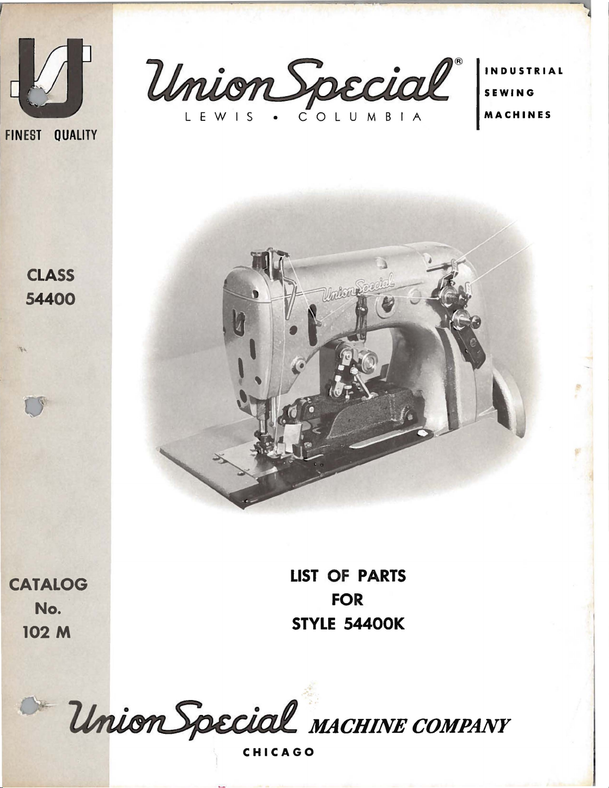
LIST
OF
PARTS
CATALOG
FOR
No.
102M
STYLE
54400K
MACHINE
CHICAGO
COMPANY
Page 2
Aid
Plant Layout!
Boost Production!
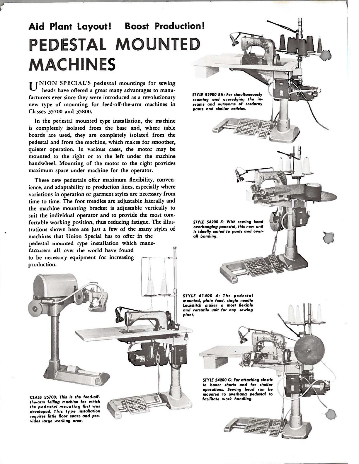
PEDESTAL
MACHINE
UNION
SPECIAL'S
pedestal
MOUNTED
S
mountings for sewing
heads have offered a great many advantages to manu-
facturers ever since they were introduced
of
new type
Classes
mounting for feed-off-the-arm machines in
35700 and 35800.
as
a revolutionary
In the pedestal mounted type installation, the machine
is
completely isolated from the base and, where table
boards are used, they are completely isolated from the
pedestal and from the machine, which makes for smoother,
quieter operation. In various cases, the motor may be
mounted to the right
handwheel. Mounting
or
to the left under the machine
of
the motor to the right providE's
maximum space under machine for the operator.
These new pedestals offer maximum flexibility,
convenience, and adaptability to production lines, especially where
variations in operation
time to time.
The
the machine mounting bracket
suit the individual operator
fortable working position, thus reducing fatigue.
trations shown here are just a few
or
garment styles are necessary from
foot treadles are adjustable laterally and
is
adjustable vertically to
and
to provide the most com-
The
illus-
of
the many styles
of
machines that Union Special has to offer in the
pedestal mounted type installation which
manufacturers all over the world have found
to be necessary equipment for increasing
production.
STYLE
52900
seaming
seams
and
pants
and
STYLE
54200 K: With
overhanging
ideally suited
is
all
banding.
BH:
For simultaneously
and
overedging
outseams
similar articles.
pedestal,
to
pants
of
corduroy
sewing
this
new
and
the
in·
..
head
unit
over·
CLASS
35700: This is
the-arm
the
developed.
requires little floor
vides
felling machine for which
pedestal
large
mounting
This
working
type
space
the
ino
area.
feed-off-
first was
tallation
and
pro·
STYLE 6 J
mounted, plain feed, single
Lockstitch
and
plant.
---
-
400
mak
versatile unit for any
STYLE
boxer
to
operations.
mounted
facilitate work handling.
A:
The
pedestal
G:
For
shorts
Sewing
overhang
needle
sewing
attaching
and
head
es a most flexible
54200
to
elastic
for similar
can
pedestal
be
to
Page 3
Catalog
(Supplement
to
Catalog
No.
102
No.
M
102
L)
The
furnished
parts
at
LIST
CLASS
listed
list
First
OF
Style
54400
in
prices
Edition
PARTS
54400
K
this
fo
catalog
r
repair
are
s
only.
October,
1963
Union
Rights
Copyright
Special
Re
s e r
by
ved
Mach
in
1961
All
MACHINE COMPANY
INDUSTRIAL
Pr
SEWING
CHICAGO
i nted
in
MACHINES
U.S.A.
3
i n e
Countr
Co.
ie
s
Page 4
IDENTIFICATION
OF
MACHINE
Each
the
name
Standard
letter
When
II
Z
only
standard
Styles
which
differs
This
catalog
therewith.
other
styles
common
locate
the
number,
reference
This
catalog
It
can
also
References
operator's
is
toward
Union
plate
Style
11
Style
Special
on
the
numbers
•
Example: 11Style
minor
changes
number.
of
machines
from the
is a supplement
Only
to
listed
all
parts
in
machines
54400 K parts.
description
numbers.
applies
be
applied
to
direction,
position
the
operator.
while
machine
machine.
have
is
Style
one
54400
are
made
Example: 11Style
similar
style
in
number,
APPLICATION
to
found
Catalog
are
on
No.
Style
listed
Opposite
and
amount
specifically
with
discretion,
such
as
seated
identified
numbers
or
more
11
K
•
Special
in a standard
construction
in
that
Catalog
No.
54400
102
L,
and
the
illustrated
required,
to
the
to
right,
at
the
left,
machine.
by a Style
are
letters
Style
54400
KZ
are
it
contains
OF
CATALOG
102
K,
but
are
illustrated.
other
parts
which
Standard
some
front,
number
classified
suffixed,
numbers
machine,
11
•
grouped
no
letter.
Land
not
should
on
Style
are
page
are
have
style
of
Special
back,
Operating
which
as
standard
but
never
contain
11 Z11
a
is
under a class
Example: 1154400
be
used
54400 A or
For
clarity,
shown
listed
been
in
each
itemized
machine
machines
etc.,
are
direction
is
stamped
and
contain
the
letter
suffixed
in
conjunction
some
phantom
part
as
listed
in
this
given
of
handwheel
special.
number
any
to
by
by
herein.
Class.
from
into
th
11
II
Z
to
the
11
of
the
parts
help
part
detail
the
•
•
Streamlined
in
Line
Light
With
Weight
Mechanism,
Lubricating
Assembly,
54400
K-3/16
uniform
made
specification
54400
54400
54400
and
and
and
K-1/4
with
K-3/8
with
K-5/8
with
Flat
Feed,
Needle
System,
Light
dresses,
of
light
Same
parts
Same
parts
Same
parts
Bed,
Low
STYLE
Throw,
OF
Single
PreparedWithPinkingAttachment,
Presser
Bearing
Weight
For
seaming
to
40
1-SSa-1.
as
furnished
as
furnished
as
furnished
Bar,
Filter
Pulley
slips,
medium
Style
Style
Style
Light
Needle
Type
and
and
half
weight
54400
for
54400
for
54400
for
Weight
Bar
Oil
Return
Prepared
simultaneously
slips,
blouses,
material.
K-3/16exceptpreparedfor
5/16
inch
K-3/16
1/2
inch
K-3/16exceptpreparedfor
3/4
inch
MACHINE
Needle
Drive,
Pump,
width
except
width
width
Machine,
Needle
Single
Oil
for
Oil
pinking
slacks,
Width
of
prepared
of
pink.
of
pink.
With
Looper
FrontDisposalofTrimmin
Bar
Reservoir
Pan
and
Base
Needle
Enclosed
Plate
Shield.
on
women's
robes
of
and
pink
1/4
similar
3/16
inch
pink.
for
3/8
inch
5/8
inch
Bar
and
street
inch.
width
width
width
Traveling
g
Driving
Automatic
Oil
Siphon
dresses,
garments
Seam
of
pink
of
pink
of
pink
s,
NOTE:
Fraction
point
of
denotes
pinking
the
knife.
width
of
pink,
measured
4
from
centerline
of
needle
to
Page 5
NEEDLES
Each
number
The
lade
Collectively,
Standard
shank,
eye,
To
sample
on
label.
Size
Selection
Thread
formation.
This
views
seen
will
be
number
Union
denotes
size
036".
number,
measured
round
spotted,
have
needle,
should
catalog
of
the
in
their
found
of
the
needle
point,
chromium
needle
A
complete
of
various
actual
the
pieces
Special
the
stamped
in
thousandths
type
or
the
the
proper
pass
has
been
listing
required
needle
kind
for
extra
orders
freely
sections
position
of
number
Style
short,
plated -sizes
type
and
order
needle
through
ORDERING
arranged
of
the
in
has
both a type
shank,
on
the
of
an
and
the
54400 K is
double
promptly
size
would
size
to
of
the
in
the
parts
the
particular
point,
needle
number
read
the
simplify
mechanism
machine.
with
length,
shank,
inch,
size
number
Type
groove,
029, 032,
and
accurately
as
should
needle
REPAIR
their
number
midway
113 GS
struck
should
follows:
be
determined
eye
PARTS
the
ordering
are
On
part
view
being
and a size
groove,
denotes
between
is
the
036,
040, 044,
filled,
be
forwarded.
"1000
in
order
shown
the
page
numbers,
shown.
finish
the
the
complete
in
size
groove,
Needles,
by
to
of
repair
so
opposite
number.
and
largest
shank
symbol.
036.
spiral
an
size
produce a good
that
descriptions,
It
049,
empty
Use
of
parts.
the
the
The
other
diameter
and
the
has a round
groove.
054.
package,
description
Type
thread
Exploded
parts
illustration
type
details.
of
eye.
ball
113
GS,
used.
stitch
may
be
and
the
a
&i
ndicate
•
never
column.
catalog,
parts
in
number.
symbol
appears.
OF
Union
Company,
'
to
Maximum
The
In
the
Where
Each
IMPORTANT!
MACHINE
Success
the
numbers
the
position
be
used
those
for
description,
which
Special
most
cases
no
specific
the
various
construction
A
part
distinguishes
part
in
the
Needles
its
subsidiaries
approved
efficiency
in
in
ordering
and,
too
number
ON
FOR
USE
operation
the
of
that
parts.
where
usage
machines
if
necessary,
permits,
small
represents
ALL
WHICH
GENUINE
and
and
scientific
and
durability
first
a
will
for
PART
of
Repair
column
part
in
Always
part
it
ORDERS,
these
is
be
mentioned
are
not
IDENTIFYING
each
its
complete
from
the
IS
NEEDLES
machines
Parts,
authorized
principles
are
are
reference
the
illustration.
use
the
common
the
same,
the
difference
UnionSpecialpart
another
same
PLEASE
ORDERED.
as
distributors.
assured.
to
in
the
PARTS
catalog
part
part
INCLUDE
AND
can
furnished
and
part
all
of
the
description.
specific
will
stamping
similar
regardless
REPAIR
be
secured
made
numbers
The
reference
number
the
be
is
in
PART
PARTS
by
the
They
with
only,
listed
machines
However,
usage
shown
stamped
is
appearance.
only
Union
are
will
in
identified
of
catalog
NAME
by
the
Special
designed
the
utmost
the
and
number
in
the
covered
be
mentioned
illustration.
with
its
by a letter
in
AND
use
of
according
precision.
merely
should
second
by
this
when
Machine
the
catalog
which
STYLE
genuine
it
5
Page 6

USE
GENUINE
NEEDLES
AND
REPAIR
PARTS
(Continued)
Genuine
parts
your
shipments
unless
must
viscosity
gauge
red
than
throw-out
are
guarantee
Prices
otherwise
The
be
Oil
is
on
lines
The
an
occasional
needles
stamped
are
are
oil
has
filled
machine
of
200
filled
the
front
on
the
pin,
before
are
wi
th
of
the
highest
strictly
forwarded
directed.
been
to
at
and
drained
beginning
250
the
spring
of
gauge.
is
almost
drop
the
the
packaged
the
familiar
quality
net
cash
f.
o.
b.
A
THREADING
from
seconds
cap
machine.
The
capacity
entirely
of
oil
looper
holder
with
and
shipping
charge
the
to
operate.
at
100°
in
the
at
both
labels
Union
in
TERMS
top
The
of
automatically
frame
marked
Special
materials
are
subject
point.
is
made
AND
machine
Use a straight
Fahrenheit.
cover
oil
level
the
oil
bearings
locking
~
trade
and
workmanship.
to
Parcel
to
cover
OILING
before
and
the
should
reservoir
lubricated,
of
the
pin,
mark.
change
Post
shipments
postage
shipping,
mineral
level
is
be
maintained
is
12
retainer
are
required.
•
Genuine
Each
without
and
and
oil
checked
ounces.
and
no
holder,
repair
trade
mark
is
no~ll
are insured
insurance.
the
reservoir
with a Saybolt
at
the
sight
between
oiling,
the
the
othe
loope
r
r
NOTE:
knife
lever
on
the
time,
which
reservoir,
reservoir
handwheel.
threaded.
a
and
back
lever
the
A
oil
On
plane
is
to
bearings
daily
it
threaded
attachment.
in
may
has
the
at
front.
All
shaft
check
the
gone
making
may
next
Please
right
moving
and
main
be
well
be
page
angles
from
front
knife
before
reservoir
to
through
too
drained
is a diagram
note,
right
parts
and
rear,
holder
the
is
manually
the
frequent
at
that
the
to
the
to
left.
of
the
also
shaft.
morning
kept
between
oil
machine,
oilings
the
plug
needle
direction
Also
pinking
oil
two
Major
start
the
pinker
is
filtered
unnecessary.
screw
showing
is
inserted
of
line
please
attachment
oil
holes
pinker
should
the
the
two
and
in
the
manner
of
feed,
note,
be
the
and
in
to
be
for
lubricating
oiling
red
main
that
points
made,
lines
other
pumped back
Excessive
frame
in
the
needle
the
spot
the
looper
oiled
to
on
suggested
which
once
are
see
that
the
oil
directly
the
bar
or scarf
is
daily.
both
marked
the
gauge.
points.
into
the
in
the
under
machine
with
the
to
threaded
side
in
level
At
main
eye
the
from
Oi
s of
red
of
this
Oil
main
the
is
in
left,
l
6
Page 7

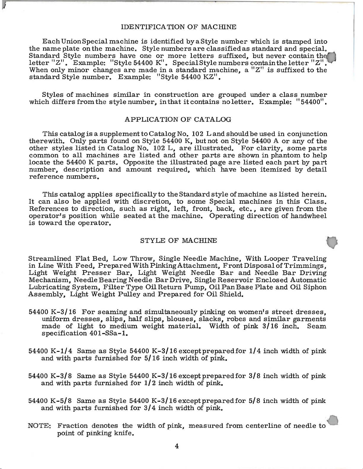
THREADING
AND
OILING
DIAGRAM
FILL
MAIN
RESERVOIR
HERE
FOR
STYLE
54400
K
CAUTION!
FILL
ALL
OIL
BEFORE
MACHINE HAS
BEFORE
STARTING.
SHIPPING.
7
RESERVOIRS
BEEN
DRAINED
Page 8

8
Page 9

SEWING
PARTS
COMBINATIONS
AND
MISCELLANEOUS
PARTS
Ref.
No.
1
2
3
4
5
6
7
8
9
10
11
12
13
14
15
16
16A
17
18
19
20
21
21A
21B
22
23
24
25
26
27
27A
27B
27C
27D
27E
27F
27G
27H
28
29
30
31
32
33
34
35
36
37
38
39
40
41
~
44
45
46
47
A8
49
50
51
52
-
Part
No.
54420
K-5/16
54420
K-3/4
54430 A
91
35730 Y
54430D
54430
B
K-5/16
54430
54430
K-3/4
54430 C
22734
AC
52930
604
22799 A
8-66
408-75
408-79
22798
87
54424
K-3/4
54424
K-3/16
22839
54480
51280 J
HA61 D
54405
K-5/16
54405
K-3/4
54405
K-3/16
54484
N-5/8
54484
N-3/4
12986
B
54264
C
22542
54478
23441 M
475-68
99-143
99-329
21210 A
810 L
18-422
18-353
40-86
54480
A
54484
J
660-237
98A
52 A
54484
P
605
54401 B
22574
80
51493 A Y
51493
BG
51493
BK
54417
A
22819
~
27-484
51258
A
22768
51254
D
51254
C
51270 B
95
539
51493
BH
51493
BJ
Presser
Presser
Presser
Presser
Presser
Screw----------------------------------------------------------Screw
Throat
Throat
Screw
Throat
Screw,
Feed Dog,
Feed Dog, f
Feed Dog,
Knife
Knife
Screw
Sprin
Screw
Chip
Edge
Throat
Swinging
Screw-----------------------------------------------------------
Looper
Knife
Screw
Cloth
Screw
Screw
Oil
Base
Lint
Needle
B-11~:··~---Ey
Needle
Screw
Needle
Needle
Needle
Screw----------------------
Frame
Filter
Description
Foot,
Foot,
Presser
Screw----------------------------------------------------Plunger
Pin---------------------------------------------------------Yield
ing
Presser
Presser
Spacer----------------------------------------------------
Screw----------------------------------------------------Chain
Screw--------------------------------------------------------
Hin
ge
Foot
Foot
Foot
----------------------------------------------------------Plate,
Plate,
----------------------------------------------------------Plate
Dowel
for feed dog
Spacer, for
Space
-----------------------------------------------------------
g, wi
-----------------------
Chute-------------------------------------------------------
Guide
Edge
Guide ----------
Edge Gui
Holder
Washer------------------------------------------------------Screw-------------------------------------------------------Screw-------------------------------------------------------Screw--------------------------------------------------------
Washer-------------------------------------------------------
Plate
Brack
Spring
Thread
Support
----------------------
Plate-------------------------------------------------------
-----------------------------------------------------------
-----------------------------------------------------------
Pan
Base
Plate
Filter
Bar-------------------------------------------------------
Screw--------------------------------------------------------
elet
Lock
Bar
----------------------------------------------------------Bar
Bar
Thread
Needle
Cap
Washer, spo
for
Styles
for
Styles
Foot
Shank--------------------------------------------
Spring------------------------------------------------
Section-----------------------
Foot
Bottom,
Foot
Bottom,
Cutter--------------------------------------------------
Screw
Pin
th fin
Lock---------------------------------------------------
Assembly----------------------------------------------
-------------------------------------------------Guard,
Guard,
Guard,
for
Styles
for
Style
Support----------------------------------------------
----------------------------------------------------
for
Style
or Sty
for Style
------------------------------
Oil
Screen
Eyelet
Bushin
les 54400
Style
r , for
Assembly
Bushin
Styl
ge r
de
Holder---------------------------------------------
Support
et
-------------------------------------------------
Eyelet---------------------------------------------
Block-----------------------------------------------
Plate--------------------------------------
Pad,
----------------------------------------------
Washer-----------------------------------------------
------------------------------------------------
g, lower
g,
Take-u
Thre
ad
nge rubb
54400
54400
for Sty
for
Style
for
Style
54400
54400
----------------------------------------------54400
54400 K-3/16
54400
e 54400 K-5
projection--------------------------------------
---------------------------------------------
Spac
er
felt-------------------------------------------
upp
er
p Wire---------------------------------------
Eyel e
er
K-3/16,
K-3/8,
for
presser
for pre
K-1/4
-
----------------------------------------
----------------------------------------
----------------------------------------
sser
les
54400
54400
54400
K-1/4,
K-3/16
-----------------------------------
K-3/8,
----------------------------------------
t-------------
----------------------------------
K-5/8
/8
-
-----------------------------------
---------------------------------------
-
------------------------------------
-
------------------------------------
1/4
-------------------------
5/8
-------------------------
foot
foot No. 54420
K-3/16, 1/4,
K-5/8
K-5/8 ( 5/8
3/8,
-------------------------------
5/8
(5/8
(3/4
-
No.
(3/4
5/8
----------------------------inch
width
inch
width
-
------------------------
-
---------------------
----------------------54420
K-5/16---------K-3/4
3/8
inch
width
inch
width
----------------------
of
pink)-----------
of
pink)
----------
-------------of
of
-----------
- - -
pink)---pink)
----
-------
-
- - 1
---
Amt.
Req.
1
1
1
1
1
1
1
1
1
1
1
1
1
1
1
1
1
2
3
1
1
2
1
2
1
1
1
1
1
1
1
1
1
1
1
1
1
1
1
1
1
1
1
1
1
1
3
3
2
2
1
1
2
1
1
1
1
1
1
1
1
1
1
1
1
1
1
9
Page 10

10
Page 11

He f.
No.
Part
No.
1 18-558
2 119-24
119-34
3 21657 E
627
4
5
6
A
29482 A
14-171
7 3-46
8
119-25
9 99-134
10
11
12
13
14
34-26
14-172
18-178
18-544
21-309
15 18-547
16
17
18
19
20
21
22
23
24
25
26
27
28
29
30
31
32
33
34
35
:l6
37
38
39
40
41
42
43
44
45
46
47
48
49
50
51
52
53
54
55
56
57
58
59
60
61
62
1012 L
39536
AD
76-18
1003 L
54484
1160 L
18-844
J87 J
18-71
45-248
45-249
40-101
CS231
1776L
46-108
51236 A
53552 p
15037 A
92201
52882 K
22585 H
54484 H
22797
35895 L
531
18
62295 A
54484 K
95
54484 G
29480
DD
29476 LF
652
P-36
39153 G
54484 F
54484 B
54484 A
22733 B
41394 A
22791 G
18
22888 A
54484 E
53139 E
269
54484 D
98
63 54484 M
64 52841 A
65 22729 c
66
67
269
35741 A
68 18
69 22526
70
71
72
73
74
652
N-14
627
652 N-14
54484 H
53138 L
75 22894 X
PINKEH
DHIVING
PAHTS
AND
PINKEH ASSEMBLY
Description
Screw, for
Lower
Lower
Style 54400
(both
VVasher-------------------------------------
Screw,
Pi
nker
Shaft,
Pinker
Upper
Upper Knife
Upper Knife
Shaft, for
Screw, for
Screw,
Knife
Screw,
Nut
Spring
Handle,
Screw,
Pinker Drive
Nut
Kn
Screw, f
Screw,
Throw-o
Knife Throw-out
Tension
Nut
Screw-----------------------------------------------------------------Kn
Li
nk Pin--------------------Conne
N
ut----------------------------
Connecting
Gaske
Scr
ew
Pinke r Drive Lever-------------------------------------------------
Scr
lar------------------------------------------------------------------------
Col
Scr e
Nut
------------------------------------
VVa
sher
Pinker Base
S
Pinker Drive Lever
Pink
er
Housing
Pl
Gask
Pi
Nut
Scre
I
dlerGear
Eccentr ic Bushing
Nut
Pinker Dri
Pink
Lock
Scr ew
Lock
mGa
Shi
Main
Screw
lower
pinker
Pinker
Knife,
Pinker
Knife,
K-3/8
5/8
and
3/4
for
mounting pi
Assembly------------------------------
for
base-------------------------------
knife--------------------------------------------
for
Styles 54400
for
Styles 54400
(1/2
inch width of pink) and
inch width of
nker
assembly-----------------------------------
K-3/16,
K-1/4
1/4,
(5/16
3/8----------------------------
inch width of pink, for
for
Style 54400
pink)--------------------------------------------
-- - - -
-
-------------------------------
-
-----------------------------
-----------------------------
Base---------------------------------------------------------------
Pinker
Knife------------------------
-
----------------------------Holder--------------------------------------------------------Cam
upper
Throw-out----------------
knife
upper
for
upper
Tension
-------------------------------------VVasher
for
for
for
Spring,
leveling
knife
base
holder------------------------------------------knife holder
pinker
shaft-------------------------------------------
knif
e-----------------------------------------
flat--------------
base------------------
------------------------------------------------------------throw-out---------------
shaft-----------------------------------------------
-
---------------------------
---
----------------------------------
~.,.
--------------------------------
-
--------------------------------
--
---------------------------------
Lever---------------------------------------------------------
---------------------------------
ife Ten
sion Adjusting Scre
or
link
pin
for
throw-out
-----------------------------------------lever--------------------------------------------------
w-----------------------------------------------
-
-------------------------------------
ut Lever-----------------------------------------------------------
Lever------------------------------------------------------
VVashe
r,
for
upper knife cam
-----------------------------
throw-out
-
-------------------------------------
-------------------------------
ife Throw-out Link-------------------------------------------------------
-- --
ct
ing
Clevis--------------Stud---------------
----------------------------
--
---------------------------------
-
----------------------------------------------
-----------------------------------------
t------------------------------------------------------------------------
-----------------------------------------------------------------------ew--------------------
w--------------------------------------
-
------------------------------------------------
-
-
----------------------------
------------------
--------------------------------------------------Pla
te
crew-------------------------------------
Gear Drive Housi
, compl
VV
asher
Nut----------------------------------------------------Idler
Bu
shing----------------------------------------------------------------
Pink
ug S
crew----------------
et
-------------------------------------------------
n Screw
---------------------------Shaf
t--------------------------------------
ng Assem
ete
--------------------------------------
bly----------------------------------
-------------------------------------------
Gear Brac
er Drive Hous ing
ket
--------------------------------------
-----------------------------
-
-----------------------·-----------------
---------------------------------------------
-
-----------------------------
-
-------------
-
--------------------------------------------------w-----------------------------------------------
---------------
------
-----------------------------------------------------
S
Ba
Nut, left
Connec
Nu
Screw
VVasher
--------------------------
VV
asher---------------------------------------------
Shaft Gear - -- -- - -------------------------
ving Shaft Gear----------------------
crew----------------------------------
er
Connecting
ll Joint
Scr ew
ti
t, r ight thr
Hod Assembly--
---------------------------------------------
------------------------------------
th
read
---------
ng Hod--------------------------------
ead---------------------------------------
---------------------------
-------------------------------------------
sket- -
--------------------------------------------------
-----------------------
-
---------------------------
---
------------------
-- - - -
-----------------------------------
-- - -
--------------------------
-
-------------------------
-
---------------------------
- --
-------------------------
-
------------------------------
-
--------------------------
-
--------------------------
-
---------------
-
------------
-
-
-------------------------------
--
K-5/8
-
--------
-
-
-------
-
--------------
-
----------------
-
-----------
-----
-
--------
-
-----------
-
-
----------------
--------
------------------
-
----------------
-
-
-------------------
-
--------------------
-
---------
-
--------------
---------------
----------------------
-- -
----
---------------
--------------------
-- -----
-------------
---- ----------------
- - --------------------
-
-----------------
-
----------------
-
-
-----------------
-
----
---------------
-
-----------------
-
--------------
----
---------
-- -
---------
---
---------
--
---
---
-- -
--
-------------
--------------
-- -
Amt.
---
--
-
--
-
----
-
-----
------
-
---
-
--
---
-- 1
- 1
--
- 1
--
- 1
---
- - 1
- - 1
---- - 2
-- - 1
-----
----
---
Heq.
2
1
1
1
1
1
1
1
1
1
1
1
1
1
2
1
1
1
1
1
1
1
1
1
1
1
1
1
1
2
1
2
2
2
1
1
8
1
1
2
2
1
1
1
1
2
1
1
1
1
1
1
l
1
1
1
1
2
1
1
1
1
1
4
4
1
1
2
11
Page 12

12
Page 13

CRANKSHAFT,
NEEDLE
AND
LOOPER
LEVER,
HOLDER
OIL
SIPHON
PARTS
PARTS,
LOOPER
Ref.
-
No.
1
2
3
4
5
6
7
8
9
10
11
12
13
14
15
16
17
18
19
20
21
22
23
24
25
26
27
28
29
30
31
32
33
34
35
36
37
38
39
40
41
42
43
44
45
46
47
48
49
50
51
52
53
54
55
56
57
58
59
60
61
Part
No.
29476 HA
51216 M
53138
22894
52891 B
52921 B
22894 G
22729 A
51294
51294
22729 B
21212
51294
51294
51294
51294
22652
54242 DA
61354
51134
22845 B
54611
54242
54285
54285 B
54225
22768
54208
54244
54244
54244
54223 A
54245
51236 A
29348
51254
22562 A
51054
51215 J
51250 A
51250 E
51258
22768
29476
51406
22894 D
54245
L
X
660-202
u
K
643-263
666-209
666-201
N
M
666-214
7947
R
p
667
B-12
B-8
B-12
667
A
v
B-4-21
c
97 A
J87
J
A
p
E
F
A
p
H
54
78
666-149
77
KR
c
Description
Crankshaft
Needle
Main
Shaft
Screw------------------------------------------------
Main
Shaft
Oil
Seal
Pulley,
Screw------------------------------------------------
Screw
Oil
Siphon
Clamp,
Screw-----------------------------------------------Siphon------------------------------------------------
Felt
Felt
Locking
Oil
Tube
Oil
Siphon
Felt
Nut------------------------------------------------------
Screw
Oil
Tube
Dowel
Screw
Retainer
Dowel
Bushing
Taper
Screw
Retainer,
Retainer
Nut,
for
Screw
Screw
Looper
Needle
Screw
Looper,
Looper
Bushing,
Bushing,
Looper
Looper
Link
Pin-------------------------------------------------
Needle
Needle
Needle
Screw------------------------------------------------
Link
Screw------------------------------------------------
Needle
Needle
Needle
Screw
Feed
Lift
Feed
Eccentric
Assembly,
Bearing----------------------------------------
Gear
------------------------------------------
Housing----------------------------------------
Ring---------------------------------------------
for
No.
1 "V''
--------------------------------------------------Assembly
upper-----------------------------------------
Plug--------------------------------------------Plug--------------------------------------------Ring,
Lint
--------------------------------------------------Pin------------------------------------------------
---------------------------------------------------
Pin------------------------------------------------
---------------------------------------------------
looper
---------------------------------------------------
--------------------------------------------------Holder,
Guard---------------------------------------------
---------------------------------------------------
marked
Holder
Thread
Thread
Lever
Screw---------------------------------------------
Pin----------------------------------------------
Felt
Needle
Lever
--------------------------------------------------Lift
Spot
for
Connection---------------------------------------
Tube-------------------------------------------
Filter
Clamp-------------------------------------------
Holder
Pin
marked
Holder
Bar
Bar
Lever
Lever
Eccentric
Bearing, rig
--------------------------------------------
----------------------------------------------
------------------------------------------
holder-------------------------------------
marked"
"CB"
Frame-------------------------------------
left------------------------------------------
right
Take-up----------------------------------Take-up
Assembly
Connection--------------------------------Connection
Wick
Lever
Stud-------------------------------------
Eyelet
Eccentric, • 062
Screw
Bearing-------------------------------------
• 770 i
nch
throw----------------------
or
round
--------------------------------------
oil
siphon
---------------------------------------
"BS"
------------------------------------
M"
-------------------------------------
---------------------------------------Driving
-----------------------------------
-----------------------------------------
----------------------------------------Bushing ------------------------------
--------------------------------------
Assembly------------------------------
----------------------------------------
belt-------------------------
connection
ht-----------------------------
-------------------------------
Link
Link
----------------------------
inch
---------------------
-----------------------
throw--------------------
Amt.
Req.
1
28
1
2
1
1
1
2
1
1
1
1
1
1
1
1
1
1
1
1
1
1
2
2
1
1
1
2
1
1
1
1
1
1
1
1
1
1
1
1
1
1
1
1
1
1
1
1
1
2
1
1
1
1
1
1
1
1
1
1
1
13
Page 14

7
14
Page 15

THREAD
STAND, THREAD TENSION PARTS, KNEE PRESS
ASSEMBLY
AND
ACCESSORIES
Ref,
No.
1
2
3
4 21114
5
6
7 21114 A
8
9
10
11
12
13
14
15
16
17
18
19
20
21
22
23
24
25
26
27
28
29
30
31
32
33
34
35
36
37
38
39 22598 c
40
41
42
43 21664 F
44
45
46
47 21662 v
48 22650
49
50
51 21662
52
53 22557 A
54 43137 E
55
56 39536
57
58
59
60
61
62
63
64
65
66
67
Part
No,
21101 H-2
258 A
652-16
21114
21104 v
22651 CD-3
22810
21114 T
22651 CD-4
21114 u
652-16
21104 H
21114 D-2
22651 CD-5
21104
21114 H-2
22651
21114 M
21114 L
21114 S-2
21114 M
21114 L
21657-3
52892
43266
51491 c
51292 D
21114 M
21114 L
51292 A
51292 G
109
51292
51292
51292 c
80
557
51493 BC
21660 H
660-219 G
92201
12982
80
21662 R
21662 T
22894 z
21662 w
21664 c
21663 A
660-168
21664
69
21202
21388
116
118B
21388
35
780
258
w
B-24
CD-4
F-5
F-2
CE-
s
AD
FD
AU
B
Amt.
Descript
Thread
Tens
Tension
Nu~-------------------------------------------------------------
Lead-in
Tension
Tens
TensionPost-------------------------------------T
TensionSpring,
Tension
TensionPostNut--------------------------------------------Spacing
Screw---------------------------------
Lifter
Knee
6
S
cre
Socket Wren
W
Th
W
L
Nut, f
Stand,
Nut------------------------------------------------------------Washer
Spool
Spool
Felt
Thread
Screw
Screw----------------------------------------------------------Lead
Screw
Lead
Washer
Nut------------------------------------------------------------Spool
Screw
Thread
EyeletSupport--------------------------------------------------
Screw
Eyelet
Eyelet-------------------------------------------------------
Lead
Eyelet
Eyelet
ion
Eyelet
Eyelet
ion
ensionDisc--------------------------------------------------------
Sprin
Washer--------------------
Link
Press Ass
Roll Pin
Mounting
Screw---------------------------------------------------
Nut-----------------
Screw,
TorsionSpring-----------------
Screw----------------------------------------------------------Knee
Knee
Knee
re
w---------------------------------------------------------
Sc
re
w-----------------------
Sc
Washer
Knee
Spring Washer---------------
racket---------------
B
Wood
Knee
Knee
ee Press Pla
Kn
Screw
w Driver,
re
nch,
rea
d Tweeze
re
nch, _single end,
if
ter
Lever Exte nsion (not s
or 35780
complete----------------------------------------------
------------
Seat Disc
Pin--------------------------------------------------------
Pad
--------------------------------------------------------
Stand
Base
-------------------------------------------------------
Eyelet
Eyelet
Seat
Eyelet
Disc
Post
Thread
Thread
Post Ferrule------------------------------------------------
Press Lif
Press
Pre
Pre
Screw, flat head
Press
Pr ess
singl
Socket
-------------------------------------------------------
Ball
-----------------------------Support------------------------------------------------
-------------------------------------------------------
Stand
Rod------------------------------------------------
-------------------------------------------------------
Locking Rin
-----------------------------------------------------
Locking
----------------------------------------------------
Separator
Support
Gui
Eyelet--------------------------------------------
Locking Ring
----------------------------------------------~-----------
needle----------------
g, looper--------------------------------------------
------------------------
embly------------------------------------------------
------------------------------------
Brack
for
att
aching
Link-------------------------------------------------
ss
Link Connection-- -- -
------------------
ss
Lever---------------------------------------
Plate
Plate
--------------------------
3/1
6 inch round blad e, length over-a
ch, for
e end,
r----------------------------------------------
B (not shown)----
-
--------------------------------------------------
de------------------------------------------------
et
ter Arm
te
3/8
--------------------------------------------
-----------------------------------------------
Ball-------------------------------------------
Split
Socket--------------------------------------
g-------------------------------------------
Ring-------------------------------------------
-----------------------------
------------------------------------------------
---------------------------
-----------------------------------------------
-
-------------------------------------------
----------------------------------------------
--------------------------------
-
1 ·nch long- -
Lever
Cushi
----------------------------------------
9/3
3/8
---------------------------------
on---------------------------
inch hexagon
2 inch opening----------------------------
inch opening
ion
-
--------------------------
-
----------------
- -
-------------
-
-----------------
-
----------------------------
-
------------------------------
-
-----------------------
-
----------------------------
-
--------------------
-
--------------------------------
---------------------------------
-
-----------------------------------
-
-------------------------------
-
---------------
--------------------------------------
hown)--
-------------------------
-------------------
--
-----------
al
nut s
--------------
-----------------
- -----
-----------------------
-
---------------
----- -
ll
9 3
/8
-
--------------
-
----
-
-------
-
----------
-----
-------
---------
-------
----
---
---
-- - - - -- - 1
----
inches ------
-
---------
-
----
-- ----1
-
---
-- - -- - -- 2
Req.
- 1
-- 2
--
-
-- - 2
--
--
-- 1
-- - 1
--
-- 2
-----
-
---
- 1
- 1
- 1
-- 1
--
--
- ---2
-- - 1
---
- 2
--
---
- 1
-- 1
---
- 1
-
---
- 1
-- - 1
-- 1
----- 1
1
4
2
2
2
2
1
1
1
1
2
2
1
1
1
2
1
2
2
2
1
2
1
1
1
2
2
2
2
2
4
2
1
1
1
1
1
1
2
1
1
1
1
1
1
1
15
Page 16

WORLD'S
FINEST
QUALITY
*
INDUSTRIAL
SEWING
MACHINES
,,
UNION
facilities throughout the world. These offices
aid you
equipment for your particular operation. Union
Special representatives
tory trained
promptly
tion, there
serve you.
ATLANTA,
BOSTON,
CHICAGO,
DALLAS, TEXAS
LOS
ANGELES, CAL.
NEW
YORK,
PHILADELPHIA,
SPECIAL
in
and
GA.
MASS.
ILL.
N.
maintains sales
the selection of the right sewing
and
service men
and
are
able to serve your , eeds
efficiently. Whatever your loca-
is
a Union Special Representative to
Check with
Y.
PA.
him
today.
MONTREAL, QUEBEC
BRUSSELS, BELGIUM
LEICESTER
LONDON,
F
PARIS, FRANCE
---
STUTTGART, GERMANY
and
-------
Representatives
Industrial
and
cities
distributors
throughout
In
the
all
Important
world.
service
will
are
fac-
, ENGLAND
ENGLAND
•
400
N.
FRANKLIN
MACHINE
COMPANY
ST.,
CHICAGO,
ILL.
' I
60610
 Loading...