

Page 1
I N
DUSTRIAL
SEWING
FINE
ST QUALITY
STYLE
53700C
®
C 0 L U M B I A®
MACHINES
CLASS
53700
STREAMLINED
FLAT
CATALOG
No.
T100C
WITH
CLOSING
UNION SPECIAL
BED
MACHINES
UPPER
FOR
GLOVE
CORPORATION
CHICAGO
FEED
FINGERS
Page 2

Union Special
Wants
to Help\bu Cut Sewing Machine
Maintenance Costs
Union
help
maintenance costs: a record keeping system
spot machines requiring
and a parts
Machine
eat
spot these problems,
variations
system using cards provided
Record" card
plant. When a repair is required, the card is pulled
the file and the repair date, parts used, and
are entered
DAT
Special is
pinpoint
inventory
Maintenance
Repair-prone machines
up
your
maintenance dollars
of
The
first system utilizes a "Machine Maintenance
in
MAKt.,.
·a
NAM
C
I.
avwao
offering
and reduce
two
your
abnormally
system
to
practical systems
sewing machine
high maintenance,
speed routine repairs.
Records
or
inexperienced operators can
in
short order. To
Union
?pecial suggests
a simple maintenance record keeping
by
(Form
L
'""liT
237)
for
the spaces
MACHINE MAINTENANCE RECORD
I
uaco
provided
a
T"Y
La TY
I I I
eoaT
Union
each sewing machine
I'
I N
Cia
LC
DAT
I:
.I
Special.
and the card is refiled.
aC
III'IAI.NO
8YM
•Dt.
I'AAT U8C
2'31-
fO~~aintenance
1"\achll'\e
Recof
d caf
d
to
two
their
O
help
cost
DATI ~U
to
help
in
from
IIC
H
....
.
forelady
Request Card" and gives
the
their
transferred
kept
invaluable
Repair
machines require
little
a
repairs. To alleviate this situation,
recommends
parts
or
time
foreman fills
the repair
out
the
it
to
work
is started, the parts used and
cost, and the completion time.
to
the permanent "Machine Repair Record"
in the office.
Whichever system is used,
tool
to
reduce needless maintenance costs.
Part
Inventories
While record keeping tells
abnormally
to
help reduce the
that
inventory
system
downtime
manufacturers establish a
for
each type
top
of
a "Repair
a mechanic. He fills
This
data is then
management
management
high
maintenance,
caused by
Union
now has an
which
routine
Special
formal
of
sewing
in
it
does
machine they operate.
Excessive machine
downtime
mechanics can be eliminated with an orderly
inventory
no
is
spare parts.
machine
parts
of
the
most
longer a need
Long
waits
downtime
inventory
is small when the overall savings are
commonly
to
cannibalize
for
is
kept
and wasted hours
by
in-plant
needed parts. There
other
machines
for
deliveries are avoided and
to a minimum.
The cost
of
a
considered.
Style 39500 QB
The
detailed
- -
second system is
information
on repair costs is desired.
normally
- -
-•••
••
..,,
.. ---
used when
more
record cards are used: a "Repair Request Card"
(Form
(Form
234), and a "Machine Repair Record"
233). When a machine requires service, the
MACHINE
REPAIR
RECORD
CARD
NAKC'I
'8
NAM
.....
C
M~-
~" ~
:::w
~~L
·
m~
I
I
l'
,flfP;,"lo I
RE
•..
INVI.NfOIIT ...
MAIIP. NAil
MAt;H . GC
O"IIAf
OIIII
-
-
fO\tf"
-
- - \'\neReP
--
1"\ac'
- -
:~~;fd
cafd
fOltf"
Repaif
TIN C aT
TIMC
COM~CD
MC
CHANtC a NO
INW
.....
N•J=~~"'
PAIR REQUEST
..
III
AL
N o .
No
PART S U SED
..
UITN
- -
uest Cafd
Re<\
ARTC
D
--
··
--
...
. -
2'34-
H
.... __
......
Ul
..,,.,
Two
~~
I
CARD
-·
~-
--
..
••
• • a .
~ft.
..
..
Per Machine
1
2
1
2
1
1
1
2
2
2
4
1
4
1
1
1
2
1
1
2
1
1
00
of
the
Special
Spare
most
th
per Inch
Minimum
Parts
Union
Special.
Part Number
39520A
39530
39597
A
39524 B
3/32
or
39524 B
1/B
22524
39526 B
39505 B
39505
22528
93 A
22797 A
39570
14077
11-
1-
f--
-
-
39549
2258BA
39508 B
39508 A
646
225
39551
F
14077
22596 E
21225
1/8
154GA
S
For
free sample copies
and spare part
popular
Representative
Presser
Presser
Presser
Throat plate markPd "V-3
Throat plate marked "V-1/8"
Throat plate screw
Doffe
Main feed
Chaining
StrPv• '
Sl\
l s-pate
N . . upper knife clamp s
Lower
Screw
Lower looper
Upper looper marked
Screw
Needle clamp stud
Nut
for
Screw
Looper
Needles (speco
inventory
machines, contact
or
Description
loot
loot
hon
ge spring
loot
stitch to ngue marked "OS "
or
rential feed doi . 16 teeth per inch
dog marked
feed
~~~-
G
B,
/32"
I " •1e
fJ\\'L'-"
-pattS
\..\st
knif
e
lor
lower knife clamp
lor
upper looper
needle clamp
lor
needle driving arm
suage
ly
lists
write direct
tud
"CC"
~
tud
size)
of
the machine record cards
for
a variety
your
local
to
Union
Page 3
(Supplement
Catalog
to
Catalog
INSTRUCTIONS
FOR
No.
T100
No.
C
100
L)
ADJUSTING
LIST
First
AND
OF
CLASS
Style
53700
OPERATING
PARTS
53 7 00
c
Edition
March,
1979
Copyright
by
Union
Rights
Special
Reserved
UNION SPECIAL
INDUSTRIAL
Printed
SEWING
CHICAGO
in
3
1972
Corporation
in
All
Countries
CORPORATION
MACHINES
U.S.A.
Page 4
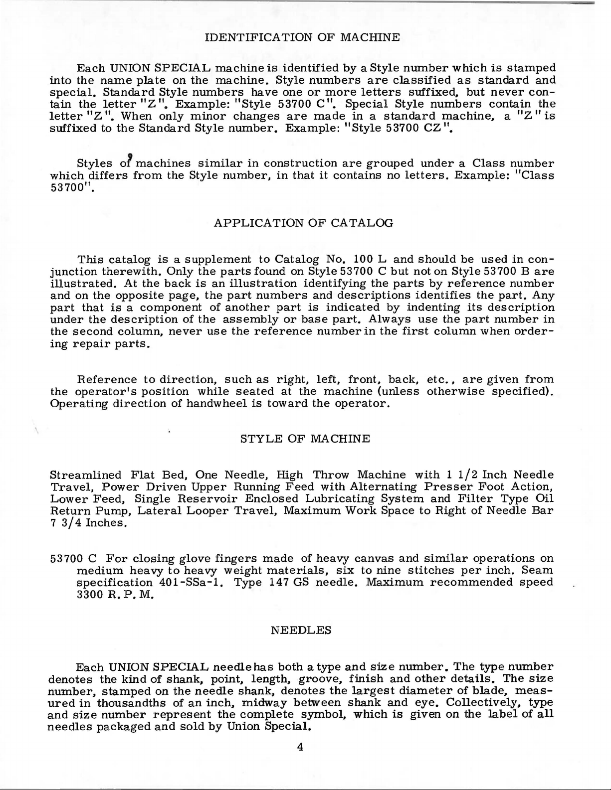
IDENTIFICATION
OF
MACHINE
Each
into
the
special.
tain
the
letter
11
Z
suffixed
Styles
which
differs
53700".
This
junction
illustrated.
and
on
the
part
under
the
ing
that
the
second
repair
UNION
name
Standard
letter
".
When
to
the
o1
catalog
therewith.
At
opposite
SPECIAL
plate
11 Z 11
on
Style
•
only
Standard
machines
from
the
is a supplement
Only
the
back
page,
is a component
description
column,
never
parts.
machine
the
machine.
numbers
Example:
minor
Style
similar
Style
APPLICATION
the
is
an
the
of
of
the
use
have
11
Style
changes
number.
in
construction
number,
to
parts
found
illustration
part
numbers
another
assembly
the
reference
is
identified
Style
one
53700
are
Example:
in
that
Catalog
on
part
or
by a Style
numbers
or
more
11
C
•
Special
made
"Style
are
it
contains
OF
CATALOG
No.
Style
53700 C but
identifying
and
descriptions
is
indicated
base
part.
number
number
are
classified
letters
suffixed,
Style
in a standard
53700
grouped
no
100 L and
under a Class
letters.
should
not
the
parts
identifies
by
indenting
Always
in
the
use
first
which
as
numbers
machine,
11
CZ
•
Example:
on
Style
by
reference
the
column
is
standard
but
never
contain
be
used
53700 B are
the
part.
its
description
part
number
when
stamped
and
con-
the
11 Z 11
a
number
"Class
in
con-
number
Any
order-
is
in
Reference
the
operator's
Operating
Streamlined
Travel,
Lower
Return
7
3/4
Power
Feed,
Pump,
Inches.
53 700 C
medium
specification
3300
Each
denotes
number,
ured
and
needles
the
stamped
in
thousandths
size
number
packaged
direction
Flat
Single
Lateral
For
closing
heavy
R.
P.M.
UNION
kind
to
direction,
position
of
Bed,
Driven
Reservoir
glove
to
40
1-SSa
SPECIAL
of
shank,
on
the
of
represent
and
such
while
handwheel
One
Needle,
Upper
Looper
fingers
heavy
weight
-1.
needle
point,
needle
an
inch,
the
sold
by
as
seated
is
STYLE
Running
Enclosed
Travel,
Type
has
length,
shank,
midway
complete
Union
right,
at
the
toward
OF
High
Feed
Lubricating
Maximum
made
of
materials,
14
7 GS
NEEDLES
both a type
groove,
denotes
between
symbol,
Special.
left,
front,
machine
the
operator.
MACHINE
Throw
with
Machine
Alternating
Work
heavy
six
canvas
to
needle.
and
finish
the
largest
shank
which
back,
(unless
System
Space
and
nine
stitches
Maximum
size
number.
and
diameter
and
is
given
etc
.•
are
otherwise
with 1 1/2
Presser
and
Filter
to
Right
similar
per
recommended
The
other
details.
of
eye.
Collectively,
on
the
given
specified).
Inch
Foot
Needle
Action,
Type
of
Needle
operations
inch.
type
number
The
blade,
meas-
label
from
Oil
Bar
on
Seam
speed
size
type
of
all
4
Page 5
NEEDLES
(Continu
ed)
Standard
shank,
point,
able
round
undersize
in
sizes
170/067.
To
have
sample
on
label. A complete
needle,
Selection
Thread
should
formation.
Success
use
of
needles
reputation
more
than
for
three-quarters
recommended
point,
eye
long,
and
double
grooves,
080/032, 090/036,
needle
of
pass
in
the
packaged
producing
or
the
the
proper
operation
orders
type
order
freely
under
would
needle
highest
of a century.
OILING
needle
one
promptly
and
size
read:
through
of
UNION
our
quality
AND
THREADING
for
Style
groove,
step
100/040,
and
number
"1000
size
should
needle
SPECIAL
brand
name,
needles
53700
struck
Cis
groove,
reduction,
110/044,
accurately
should
be
Needles,
be determin
eye
in
order
machines
~®,
in
material
INSTRUCTIONS
Type
147
ball
GS.
eye,
chromiumplated
125/049,
fill
ed,
140/054,
an
empty
forwarded.
Type
147
ed
by
to
produce
can
GS,
size of
be
which
and
workmanship
It
has a round
spotted,
and
package,
Use
description
Size
140/054
thread
a
good
secured
is
backed
short
is
avail-
150/060.
used.
stitch
only
by
by
for
a
11
•
a
CAUTION!
reservoir
oil
of a Saybolt
Oil
is
lucite
the
red
gauge
lines
The
manual
feed
gauge.
in
the
quired.
the
main
the
oiling.
The
drive
The
main
A
daily
Oil
main
reservoir
handw
main
Oil
has
must
filled
on
on
at
the
this
lubrication,
The
reservoir
eccentric
entire
frame
lower
by
check,
which
has
reservoir
may
heel.
been
be
filled
viscosity
the
spring
front
of
gauge.
which
oiling
and
mechanism
this
before
gone
making
be
drained
drained
before
of
90
cap
the
machine.
Capacity
is
almost
diagram
supplies
needle
reservoir.
the
morning
through
too
frequent
at
from
to
in
(Fig.
oil
lever
the
the
the
main
beginning
125
seconds
the
top
The
of
the
entirely
1)
is
to
the
crank
is
served
start,
machine
oilings
plug
screw
reservoir
to
operate.
at
100°
cover
oil
oil
reservoir
level
and
should
automatic,
self-explanatory.
looper
and
the
drive
supply
thru a system
should
is
filtered
be
unnecessary.
in
the
main
before
Use a straight
Fahrenheit.
the
level
be
maintained
is
twelve
requires
eccentric,
is
registered
of
channels
made
and
and
Excessive
frame,
shipment,
is
checked
ounces.
a
minimum
upper
oil
added
pumped
directly
so
mineral
at
between
running
at
and
wicks
if
back
oil
in
under
the
the
of
front
re-
into
the
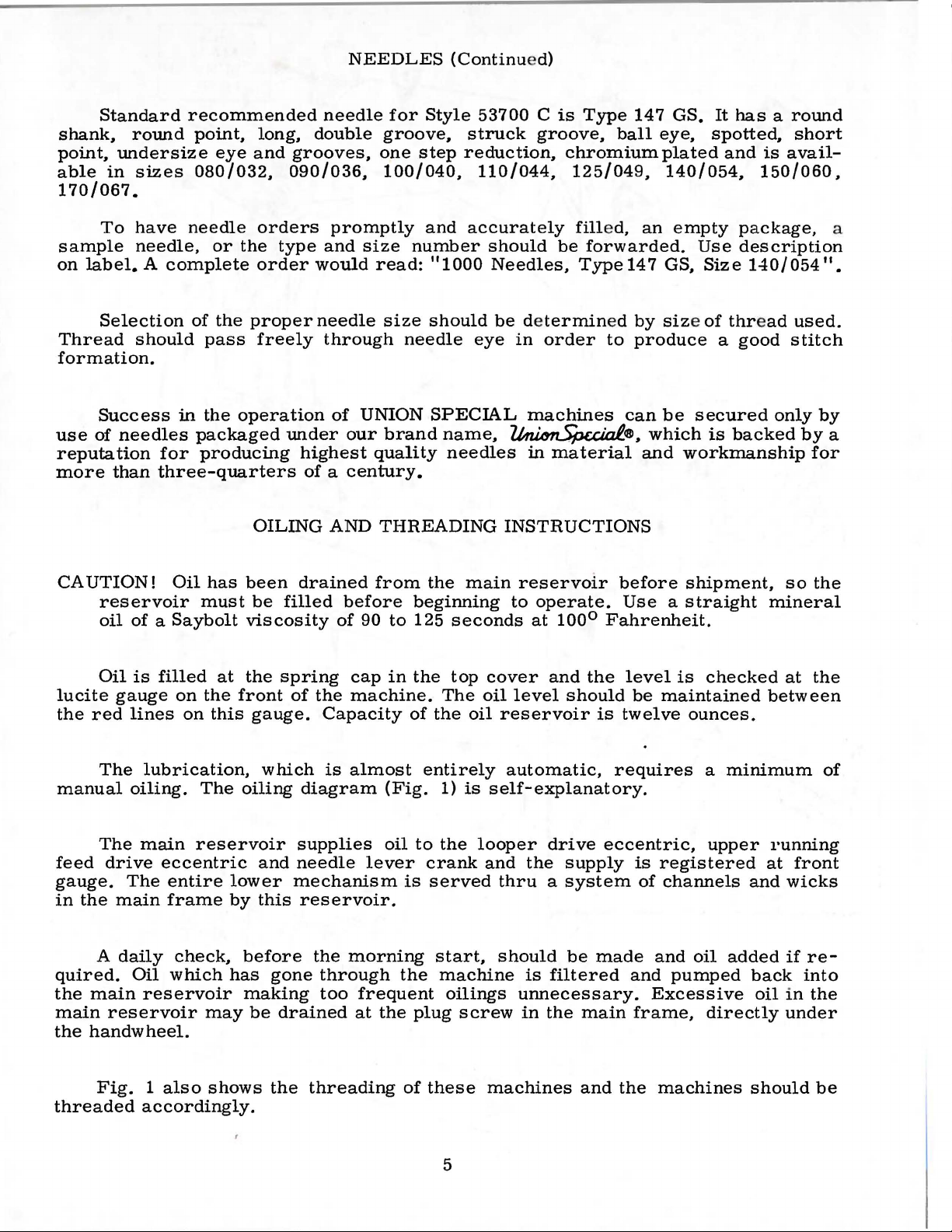
Fig. 1 also
threaded
accordingly.
shows
the
threading
of
these
machines
5
and
the
machines
should
be
Page 6

FILL
MAIN
RESERVOIR
HERE
KEEP
OIL
LEVEL
BETWEEN
LINES
CAUTION!
FILL
ALL
OIL
RESERVOIRS
BEFORE
MACHINE
BEFORE
STARTING.
HAS
BEEN
SHIPPING.
DRAINED
6
Fig.
1
Page 7

SYNCHRONIZING
LOOPER
AND
NEEDLE
MOTIONS
Check
21227
AC
Insert
gauge
the
plate
indicator
pointer
in
the
operating
gauge
top
plate
of
screw
the
pin
the
indicator
scale
in
rear.
is
the
operating
If
NOTE:
follows:
Insert
direction
of
the
needle.
then
turn
the
left
height
variation
point
move
acts
of
the
the
the
as
the
on
to
the
and
the
needle
and
note
again
allowable.
the
reading
If
gauge
the
until
handwheel
and
is
of
the
of . 005
the
looper
looper
reverse.
synchronization
follows:
pin,
which
the
throat
portion
right,
of
but
direction
set
the
indicator
bar
and
indicator
contacts
will
the
return
If
the
direction,
is
lower,
No.
21227
looper
the
Note
in
point
the
height
in
even
with
eye
of
the
needle
inch
is
is
greater
drive
lever
Moving
is
included
plate
the
do
gauge
not
seat
tighten
until
the
right
reading.
plate.
to
the
reading
the
looper
the
AC
the
looper
of
the
looper,
of
the
reverse
the
left
with
allowable.
when
rocker
of
the
looper
of
the
so
If
the
same
is
rocker
is
not
the
side
the
looper
with
using
in
the
the
pin
in
that
end
Turn
motions
reading.
higher
drive
available,
rocker
moving
eye
of
direction
of
respect
If
the
the
handwheel
to
the
drive
the
the
needle
set
the
the
of
the
the
handwheel
on
lever
will
and
the
the
needle.
distance
rear.
lever
and needle
gaug
e,
in
throat plate
thread
screw
looper
left
end
at
rocker
of
pointer
are
in
synchronization,
A
variation
the
scale
rocker
have
to
synchronization
turn
to
needle
until
to
the
the
the
with
the
If
looper
from
is
turned
Moving
rocker
motion
the
screws
take-up
this
time.
the
rests
in
the
when
will
be
moved
handwheel
left,
is
respect
looper
the
motions
point
the
in
it
is
s,
using
looper
rocker.
for
attaching.
wire
Turn
contacts
pointer
at 110
reverse
of
one
the
handwheel
have
to
the
rests
11
•
Tighten
direction
graduation
to
be
the
may
be
in
even
to
point
with
the
again
synchronize,
will
be
eye
of
the
the
operating
in
the
opposite
accomplished
gauge
Place the
hole
the
handwheel
edge
against
the
pointer
is
moved
front.
checked
the
operating
the
looper
moves
the
same.
needle
direction,
direction
as
No.
Plac
with
of
the
the
the
the
set
until
on
the
turned
to
the
as
left
side
point,
the
to
the
follows:
e
of
to
A
Remove
reservoir
drive
as
ing
as
eccentric
far
to
required.
remove
bushing
shoe
thick
shaped
between
bushing
ectly
ism
reposition
(per
ly.
Insert a new
with
Fig.
spot
2)
should
If
adjustment
hand
or
can
nut
not
thread)
backward
be
(C),
bind
top
to
the
the
front
the
before
when
spot
or
at
its
be
5/3 2 inch
used
then
after
the
cloth
cover
and
plate,
loosen
mechanism
right
CAUTION:
plug
metal
SETTING
as
or
screw
driving
the
looper
driving
the
screws)
it
will
the
middle
To
to
washer
the
looper
and
THE
needle,
scarf
farthest
to
the
position
from
is
required,
and
nut
(C)
to
obtain
the
advantageously
nut
(B).
Make
adjustment.
throat
the
and
go.
Drive
bushing
avoid
in
the
bed
the
front
approximately
drive
lever
bushing
drive
tighten
LOOPER
type
rear.
and
With
to
the
centerline
loosen
on
5/32
nut
connecting
inch
in
making
sure
plate
screws
move
in
the
the
to
distorting
behind
and
place a horse-
and
to
the
rear.
eccentric
all
screws
size
as
the
the
right,
of
(B)
(it
rod
dimension
this
the
left
support,
the
looper
eccentric
rear
bush-
the
rear,
the
parts,
the
1/16
adjacent
Corr-
mechan-
secure-
specified,
looper
its
point
the
needle.
has a left
(D)
and
(Fig.
adjustment.
ball
joint
oil
rear
inch
(A,
turn
2).
the
Looper gau
is
in
vertical
Fig. 2
connecting rod
ge No.
Retighten
both
position
forward
21225-5/32
nuts,
and
fir
doe
s t
s
7
Page 8

The
needle,
adjustment
reposition
when
looper
is
looper
is
set
its
point
necessary,
as
required
SETTING
correctly
passes
loosen
THE
in-line-of-feed,
as
close
screw
and
retighten
LOOPER
as
possible
(E,
Fig.
screw
(Continued)
as
it
moves
without
2)
in
looper
(E).
to
the
contacting
rock
left
the
shaft
behind
needle.
arm
the
If
(F),
needle.
(B)
all
above
Height
supporting
dog
ance
right
NOTE:
up
or
Set
sides.
the
can
holder
can
or
feed
If
the
left,
Whenever
Fig.
adjustment
down
throat
be
rocker
as
feed
See
that
be
set
screw
adjusting
set
as
3
is
required
dog
(A,
the
tips
plate
(C).
by
required.
arm
and
by
loosening
Parallelism
screw
loosening
the
feed
(G)
necessary,
and
retighten
SETTING
Fig.
does
4)
of
the
are
(A,
screws
rocker
not
in
parallel
feed
Fig.
loosen
the
teeth
dog
can
has
bind.
THE
throat
extend
with
attaching
be
5),
as
(E.
been
SETTING
The
when
the
er
screw
Fig.
the
underside
point
screw
FEED
plate
slightly
the
set
by
required
4)
moved,
HEIGHT
height
top
is
flush
(A,
(A).
DOG
so
throat
screw
loosening
and
and
moving
always
of
of
its
of
the
Fig.
there
less
plate
(B)
retighten
Fig.
OF
the
eye
looper.
with
3)
and
is
than
at
and
nut
feed
check
4
NEEDLE
needle
is
1/64
the
move
equal
the
high
adjusting
(D)
and
nut.
rocker
to
is
inch
when
left
side
needle
clearance
depth
point
rotating
Side
assure
BAR
correct
below
the
loop-
of
the
bar
on
of a tooth
of
travel.
feed
dog
feed
clear-
(F)
to
the
that
the
End
and
clearance
moving
feed
can
rocker
be
(F)
set
by
forward
loosening
or
backward
8
screws
as
(H)
required.
in
the
feed
rocker
arm
(G)
Page 9

The
first
the
needle
turned
top
screw
in
INITIAL
feed
in
the
bar
has
the
operating
SETTINGS
eccentric
eccentric
risen
direction.
assembly
will
1/4
inch
OF
UPPER
should
be
in a perpendicular
from
the
RUNNING
be
located
bottom
of
FEED
on
the
position
its
stroke,
MECHANISM
main
to
the
with
shaft
main
the
so
that the
shaft
handwheel
when
NOTE:
mechanism
centerline
of
the
upper
inch
(Fig.
The
should
(B).
if
be
This
required.
The
next
Fig.
5
of
the
feed
6).
Retighten
bell
crank
set
all
connecting
two
which
link
pin
drive
lever
the
rod
paragraphs
can
be
in
the
re
c t
needle
bottom
While
handwheel,
the
d r i
Fig.
ing
nut
tance
(C)
and
rock
nut
(B).
ball
way
to
the
can
also
refer
lowered
Turn
upper
vi
6)
shaft
joint
handwheel
operating
ion
u n t i 1
bar
of
its
holding
n g
lever
after
(B)
so
b e t w e e n
the
centerline
(D)
(A,
right
be
lengthened
to
the
later
is
at
stroke.
position
feed
loosenthe
dis-
is
Fig.
in
the
maximum
to
suit
dithe
the
the
lift
(A, ·
the
7/8
7)
slot
or
height
sewing
of
the
upper
shortened
setting
conditions.
Fig.
feed
bell
to
suit
sewing
6
of
the
crank
top
feed
lever
conditions
As
from
between
8)
be 1 3/32
made
ward
and
the
the
by
or
Fig.
the
needle
bottom
the
rear
front
inch
loosening
rearward
of
the
(Fig.
7
bar
of
its
of
upper
screw
as
just
stroke,
the
needle
8).
Adjustment
(C)
required
feed
begins
the
bar
bar
(B)
in
the
and
to
rise
distance
(A,
Fig.
should
can
be
upper
retighten
9
feed
screw
driving
(C).
lever
Fig.
(D)
and
8
moving
it
for-
Page 10

INITIAL SET
Synchronizing the upper
ing
nut
(A,
ever
l
(B).
Fig.
Retight
9)
TINGS
and
en
nut.
OF
UPPER
feed
moving
the
RUNNING
with
the
ball
lower
stud
in
FEED
feed
the
upper
MECHANISM
can
be
accomplished
feed
driving
(Continued)
by
loosen-
shaft
segmen
t
Set
contact
ward
missible.
its
needle,
left,
forward
needle
To
and
wise
erly
point
vertical
is
raise
turn
to
set.
Fig.
the
the
rear
of
It
face
until
even
or
backward,
guard
or
screw
raise.
9
rear
of
travel.
should
approach
the
point
with
as
lower
(E)
Retighten
needle
the
needle
A
clearance
be
set
of
the
needle.
merely
required
the
needle
clockwise
screw
complished
left
(B).
and
the
NOTE:
guard
(B)
as
low
within
the
looper
loosen
and
guard,
to
(D)
CHANGING
Set
the
stitch
by
hand
turning
stitch.
(A,
To
lower
thread)
Turning
Any
corresponding
setting
feed
SETTING
Fig.
when
of . 005
as
possible,
about
(C),
move
retighten
after
screw
it
in a counterclockwise
change
and
mechanism
11)
at
its
3/64
moving
needle
screw
loosen
or
counterclock-
guard
to
loosening
and
turning
(B)
in
change
also
synchronization
as
THE
inch
screw
REAR
horizontally
most
is
yet
inch
of
to
guard
(D),
move
screw
is
prop-
STITCH
the
required
locknut
clockwise
stitch
described
for-
per-
have
the
the
(D).
(D)
LENGTH
(A,
the
stitch
length
in
the
previously.
NEEDLE
so
that
length.
Fig.
adjusting
shortens
direction
will
necessitate
rear
of
the
upper
GUARD
it
does
Fig.
This
10)
the
lengthens
needle
not
10
is
(it
has
screw
stitch
guard
running
quite
ac-
a
a
foot
has
Fi
reached
g.
11
its
highest pos
ition.
SETTING
Set
the
that
it
barely
point
just
may
needle guard
meet
needle
needle guard
screws
required
lower
(J),
screws aft
ly
is
travel
of
past
brush,
this
guard
or
reposition
THREAD
The
when
raised
and
the
the
but
condition
(G) ,
and
rotate
er
thread
it
begins
to
is
FRONT
front
contacts
looper
left
side
not
should
or
looper
forward
rotate
retighten
needle guard,
as
guard
TENSION
tension
to
within
entirely
needle
(C),
of
pick
be
set
yet
needle
necessary
is
properly
function
1/8
rele
NEEDLE
guard
the
needle
moving
the
needle.
at
the
needle.
as
low
not
contact
at
any
or
rearward
guard
screws
RELEASE
r elea
as
inch
as ed
se
of
when
GUARD
(F,
Fi
(B)
to
the
as pos
time.
holder
(G).
loosen
and
set.
is
set
the pre
the
the
g. 11)
until
left,
The
looper
The
sible
the
To
move
,
loosen
(H)
To
raise,
screws
retighten
correct-
sser
end
of
presser
so
the
is
front
to
rear
as
foot
its
10
Page 11

If
at
the
screw.
adjustment
back
After
of
the
adjustment
THREAD
is
needed,
machine
loosen
and
there
TENSION
tension
move
should
tension
be
RELEASE
release
disc
no
binding
(Continued)
lever
screw
separator
at
any
as
point.
(A,
Fig.
required.
12),
located
Retighten
The
it
is
possible
(B,
Fig.
mately
the
lifter
feed
foot
bar
resting
throat
If
ion
until
Fig.
3),
surface,
driver
SETTING
height
to
12)
is
1/16
inch
link
(F)
when
on
plate.
adjustment
the
needle
then,
pry
to
obtain
while
up
of
the
remove
fully
clearance
(D,
Fig.
the
the
throat
is
bar
presser
the
HEIGHT
presser
the
presser
depressed.
3)
and
foot
lifter
plate,
necessary,
is
in
holding
bar
connection
1/16
inch
OF
bar
Also,
between
the
lever
with
turn
the
low
presser
setting
PRESSER
(C,
Fig.
foot
when
there
the
bottom
stud
(E)
is
released
the
feed
handw
heel
position.
foot
down
and
and
retighten
into
piece
(Fig.
machines.
BAR
3)
is
set
the
foot
should
end
located
and
dog
down
in
operating
Loosen
on
the
guide
(H)
Draw
the
machine
of
fabric.
1)
for
SETTING
WIRE
correctly
be
of
in
the
lifter
the
lever
approxi-
slot
the
upper
presser
below
direct-
screws
throat
plate
with a screw-
screws.
THREADING
the
looper
and
Refer
manner
NEEDLE
AND
FRAME
if
of
the
(G,
and
needle
start
to
operating
threading
of
threading
THREAD
EYELET
Fig.
12
threads
on
diagram
these
TAKE-UP
a
Set
to
the
needle
The
that
the
comes
quired
finger
Regulate
that
it
work
ing
uniformly
it
reverse.
the
needle
machine
thread
is
SETTING
looper
looper
up
out
of
byloosening
has
been
the
exerts
only
clockwise
Fig.
13
thread
base
and
midway
desired
in
LOOPER
thread
thread
the
retainer
is
material.
screws
properly
set,
PRESSER
presser
enough
when a slight
increases
frame
in
the
stitch
finger
cast-off
Co-ordinated
(Band
retighten
FOOT
spring
pressure
tension
the
pressure,
eyelet
its
(C,
mounting
or
raise
THREAD
(A,
just
after
C).
After
screws.
PRESSURE
regulating
on
the
is
placed
counterclockwise
Set
the
needle
(A,
Fig.
even
bar
thread
is
at
setting
or
raise
Fig.
with
the
13)
slot.
for
13)
so
the
top
eyelet
bottom
for
a
smaller
it
for a larger
perpendicular
Lower
less.
TAKE-UP
Fig.
14)
should
the
eye
of
the
positioning
can
looperthreadretainer
screw
presser
on
(D,
the
foot
fabric.
Fig.
to
that
of
if
be
feed
acts
thread
its
of
the
(B)
when
its
more
set
so
needle
be
ac-
13)
so
the
Turn-
the
upper
hole
the
stroke.
needle
loop.
take-up
surface
in
the
needle
Lower
thread
Fi
g.
wire
is
needle
bar
this
loop
14
11
Page 12

12
Page 13

The
that
parts
are
illustrated
used
on
Style
on
the
53700
preceding
C,
but
not
page
used
and
on
described
Style
53700
below
B.
represent
the
parts
Those
to
Use
this
Reference
indented
assembly.
Ref.
No.
1
2
3
4
5
6
7
8
9
10
11
12
13
14
15
16
17
18
19
20
21
22
23
24
25
26
27
28
29
30
parts
Styles
Catalog
catalog.
53754
53754
55235
55235
41336
53720
53726
53753
53726
53705
53724
53770
22799
51236
51236
51236
53722
29476
22559
51325
51242
51281
21657
22517
53701 A
shown
53700
numbers
descriptions,
Part
No.
77
6042
Band
No.
100 L (Style
K
J
D
A
E
c
B
78
E
J
D
B
376
A
B
21-335
E
F
G
A
DD
E
L
U-207
E
s
24
B
in
phantom
C.
that
indicate
Screw,
Upper
Upper
Link
PresserFoot--------------------------------------
Top
Lower
Screw,
Throat
Feed
Feed
nflain
Crank
Looper
Washer,
Cloth
Washer
Edge
Screw,
Cloth
views
53700
are
inside a bracket
for
Running
Running
Locking
Locking
Locking
Pin
Screw----------------------------------------Feed
Top
Feed
Top
Feed
Feed
for
Plate---------------------------------------
Chain
Spring
Screw-----------------------------------------
Crank
Ferrule---------------------------------------
Crank
Shaft-----------------------------------------
Shaft
Screw-----------------------------------------
Needle
Plate
-------------------------------------------
Guide----------------------------------------
for
Plate
and
bearing
B)
for
they
------------------------------------------
Dog
for
are
component
Description
link
pin
No.
Feed
Feed
Stud----------------------------------Stud
Stud
Assembly
Dog
Dog,
Dog,
feed
Cutting
---------------------------------------Link
Stud
Assembly, • 990
Guard-------------------------------
No.
Cover----------------------------------
edge
(not
Lift
Lift
Washer
Nut-------------------------------
Shank----------------------------
marked
14
dog
--------------------------------
Knife,
Assembly--------------------------
-----------------------------------
53754 F ---------------------------
guide
shown
no
reference
all
parts
or
box
41336 C ---------------------
Driving
Driving
---------------------------
---------------------------"FH"--------------------
teeth
per
marked
inch
-----------------------------on
picture
numbers
not
illustrated
on
the
picture
parts
inch-------------------
of a
Link---------------Lever---------------
"L"
----------------
throw---------------
plate)---------------
or
plate
complete
are
common
described
and
part
Amt.
in
have
or
Req.
1
1
1
1
1
1
1
1
2
1
1
1
1
1
1
1
1
1
1
1
1
1
1
2
1
2
1
2
1
1
1
13
Page 14

Here
are
Oil
for
Specifications
Union
Sewing
1.
For
Wt:ere
Specification
oil,
viscosity
for
all
Specification
oil,
viscosity
or
with a maximum
use
where freedom from
Specification
oil,
viscosity
Specification
quality
It
is
No.
grease
similar
3 grease
SPECIAL
roleum
mended
machines.
roleum
white
mount.
roleum
high
mitters.
3.
used.
UNION
SPECIFICATION
Viscosity S.S.U. at
Flash
(Min.)
Pour
(Max.)
Color
A.S.T.M.
Neutralization
Viscosity
(D
Compounding
Copper
*Anline
*Used
Index
& D
Min.)
Corrosion
No.
with
Buna N
174
100
oiling
175 specifies a high
87 specifies a high
300
100
for
to
commercial
is
NO.
100°F
(Max.)
No.
(Ma
(Max.)
Rubber
Special
Machines
specifies a high
seconds
applications
100
seconds at
A.S.T.M. color
oil
seconds
use
not
at
specifies a general purpose
in
ball bearings and trans-
N.L.G.I.,grease
obtainable,
174 175 87
90-125
350
20 20
3 1 3
0.10 0.10
x.)
85 85 85
None
1A
175-225
"0"
Retainers
at
100°F.
on
staining
100°F.
90-125
None
175-225
quality
Recom-
high speed
quality
100°F.,
number
is
quality
No. 2 may
300-350
350
1A
175-225
pet-
pet-
water
of
para-
pet-
No.
be
350
20
0.10
None
1A
•
"
NOTE
meeting
essential. These
These additives
and
separate.
NOTE
shall
1:
The
above classification is desirable
1.
Oxidation
2. Rust
3.
Lubricity
4.
Anti-oxidants
5.
Film
not
removable
2:
Oils
not
be
used
1.
Extreme
2.
Tackiness
3. Lead soap
4.
Detergent
FINE
ST QUAli
TY
use
of
non-corrosive
may
include:
inhibitors
inhibitors
additives
strength additives
must
be
completely
by
wick
feeding
containing
at
pressure a
U
NION
any
or
adhesive
additive
s
the
following
time:
dditives-corrosive
additives
s
SPECIAL
CORPORATION
additives
soluble in the
nor
type
in oil
but
shall
additives
s
not
oil
they
Page 15

Helpful,
cient
machine sewed
Sales
esting,
obligation
authoritative information
types
of
Promotion
illustrated
are the
equ i
pment
article
is
Department.
bulletins
following
ava
for
making
ilable
from
Among
that
are available
:
on
the
virtually
Union
the
many
most
Special
without
eff
any
inter-
i·
HERE
ARE
HELPFUL
No.
240,
No.
249,
No.
250,
No.
251,
No.
252,
No.
253,
No.
254,
No.
256,
No.
~
59,
No.
260,
No.
262,
No.
263,
No.
264,
No.
265,
No.
266,
No.
267,
No.
268,
No.
269,
No.
271,
No.
273,
No.
610,
No.
710,
No.
730,
No.
740,
No.
750,
No. 1100,
No.
1105,
"Columbia
i
ng
Machines"
No.
1500,
"Men's,
"Rainwear"
"Men's
"Service
"Men's
"Overalls,
"Men's
"Knit
"Men's
"Work
"Cotton,
Bags"
"Men's
"Men's
"Women's
"Women's
"Corsets, Girdles, Brassieres"
"Children's
"Mattresses,
Upholstery"
"Awnings,
"Curtains & Drapes"
"Kiipp-it"
"MCS
"MCS
Hemmer"
"MCS
"Fusing
"Lewis
stitch,
"Button
"Alteration
Women's,
Dress
Shirts
Shorts
Coveralls, and Dungarees"
Knit
Outerwear"
Sports
Gloves"
Burlap,
Clothing"
Women's,
Wear"
Wear
Canopies, Tents,
ForMation
Automatic
Automatic
Presses"
Blindstitch,
Mach i
Sewers-
Blindstitch,
Children's
Shirts"
and
Pants"
and Pajamas"
Underwear"
Shirts"
Jute,
Children's
And
Wear"
Slip
Covers,
Unit"
Dual
Rib-Knit
nes"
Ticket
Saddle
Department
and
High
Furniture
Underfront
Chainstitch,
Tackers"
Stitch,
Machines"
Footwear"
Multiwall
Jackets"
Fashion"
Tarps"
Shirt
Cuff
Machine"
Lock·
and T·ie Clos-
Paper
BULLETINS
TO
SEWING
HELP
PROBLEMS
YOU
and
CATALOGS
SOLVE
UNION SPECIAL
CORPORATION
Page 16

,..o
...
'
...
Q
WORLD'S
,..,lf
FINEST
QUALITY
*
INDUSTRIAL
SEWING
MACHINES
UNION
SPECIAL
maintains sales
and
facilities throughout the world. These offices
aid
you
in
the selection of the right sewing
equipment for your particular operation. Union
and
Special representatives
tory trained
promptly
tion, there
and
and
is
a Union Special Representative
serve you. Check with
ATLANTA,
BOSTON, MASS.
CHICAGO,
DALLAS,
LOS ANGELES, CAL.
NEW YORK,
PHILADELPHIA, PA.
GA.
ILL.
TEXAS
N.
Y.
are
efficiently. Whatever your loca-
service men
able
to
serve your needs
him
today.
MONTREAL, CANADA
TORONTO, CANADA
BRUSSELS, BELGIUM
LEICESTER,
LONDON,
PARIS, FRANCE
STUnGART,
service
will
are
fac-
to
ENGLAND
ENGLAND
GERMANY
Representatives
industrial
UNION SPECIAL
400
N.
FRANKLIN
and
cities
distributors
throughout
ST.,
In
all
Important
the
world.
CORPORATION
CHICAGO,
ILL.
60610
 Loading...