

Page 1

STYLES
53700B
53800B
ADJUSTING INSTRUCTIONS AND
ILLUSTRATED PARTS LIST
STREAMLINED
FIFTY THOUSAND SERIES
CATALOG NO.
100L-GR
FIRST EDITION
01/23/09
Page 2

MANUAL NO. 100L-GR ADJUSTING INSTRUCTIONS AND LLUSTRATED PARTS LIST FOR 53700 /53800
SERIES MACHINES
First Edition Copyright 2008
BY
Union Special Corporation Rights Reserved In All Countries
Printed in U.S.A. Jan 2008
FOREWORD
The new streamlined Class 53700 and 53800 machines bring to the automobile upholstery and seat cover industry new
styling, improved lubrication, and light running high speed performance. Enclosed type oiling system for looper drive
eccentric, upper feed driving eccentric, and needle lever crank have substantially increased the speed of these
machines. The almost entirely automatic lubrication system makes maintenance simple. All parts are made by precision
methods insuring complete interchangeability.
It is our constant aim to furnish carefully prepared information which will enable our customer to secure all possible
economies from the use of Union Special sewing machines. The following pages illustrate and describe the parts for the
styles in Classes 53700 and 53800.
Union Special representatives will be found in all manufacturing centers, ready to cooperate with you to plan and estimate
requirements.
2
Page 3

CONTENTS
IDENTIFICATION OF MACHINE .................................................................................................................................................................3
APPLICATION OF CATALOG ...................................................................................................................................................................3
STYLES OF MACHINE ................................................................................................................................................................................3
NEEDLES .................................................................................................................................................................................................... 4
ORDERING REPAIR PARTS ........................................................................................................................................................................4
ORDERING REPAIR PARTS (CONTINUED) ................................................................................................................................................ 5
IDENTIFYING PARTS ................................................................................................................................................................................... 5
USE GENUINE NEEDLES AND REPAIR PARTS ........................................................................................................................................... 5
TERMS ........................................................................................................................................................................................................ 5
OILING AND THREADING ......................................................................................................................................................................... 5
0ILING AND THREADING DIAGRAM ....................................................................................................................................................... 6
SELF-PRIMING HEAD OIL SIPHON ............................................................................................................................................................ 7
INSTALLING AND MAINTENANCE OF OIL SIPHON ................................................................................................................................. 7
INSTRUCTIONS FOR MECHANICS ............................................................................................................................................................ 8
NEEDLE LEVER STUD SETTING ...................................................................................................................................................................8
OILING SYSTEM ......................................................................................................................................................................................... 8
SETTING THE ZIG-ZAG MOTION ............................................................................................................................................................... 8
SPACING NEEDLE IN THROAT PLATE .......................................................................................................................................................8
SETTING THE LOOPER ...............................................................................................................................................................................8
SETTING THE LOOPER (CONTINUED) .......................................................................................................................................................9
SETTING HEIGHT OF NEEDLE BAR ............................................................................................................................................................. 9
SYNCHRONIZING LOOPER AND ............................................................................................................................................................. 9
NEEDLE MOTIONS ..................................................................................................................................................................................... 9
SYNCHRONIZING LOOPER AND ........................................................................................................................................................... 10
NEEDLE MOTIONS (CONTINUED) ..........................................................................................................................................................10
SETTING THE FEED DOG ......................................................................................................................................................................... 10
SETTING THE FEED DOG (CONTINUED) .................................................................................................................................................11
CHANGING STITCH LENGTH .................................................................................................................................................................. 11
SETTING THE NEEDLE GUARD ................................................................................................................................................................. 11
SYNCHRONIZATION OF THE UPPER ROLLER FEED ................................................................................................................................ 12
THREADING .............................................................................................................................................................................................12
SETTING THE LOOPER THREAD TAKE-UP ................................................................................................................................................13
THREAD TENSIONS .................................................................................................................................................................................. 13
PRESSER FOOT PRESSURE ....................................................................................................................................................................... 13
SETTING NEEDLE THREAD TAKE-UP ........................................................................................................................................................ 13
SETTING SPRING RETAINERS ON LOOPER .............................................................................................................................................14
THREAD TENSION RELEASE .....................................................................................................................................................................14
SETTING THE ATTACHMENTS ................................................................................................................................................................... 14
MAIN FRAME, CAST-OFF PLATE, MISCELLANEOUS COVERS AND PLATES ......................................................................................... 17
CLOTH PLATES, CLOTH PLATE COVERS, MISCELLANEOUS AND ATTACHMENTS .............................................................................. 19
MAIN FRAME, BUSHINGS AND MISCELLANEOUS OILING PARTS ........................................................................................................ 21
FOR STYLES 53100B AND C ONLY CLUTCH ASSEMBLY, CLUTCH DRIVE SHAFT GEAR AND HOUSING ASSEMBLY .......................... 23
FOR STYLES 53100B AND C ONLY CLUTCH ASSEMBLY, CLUTCH DRIVE SHAFT GEAR AND HOUSING ASSEMBLY .......................... 25
CRANKSHAFT, NEEDLE LEVER AND LOOPER DRIVING PARTS ............................................................................................................ 27
CRANKSHAFT, NEEDLE LEVER AND LOOPER DRIVING PARTS ............................................................................................................ 29
LOOPER ROCKER AND CONNECTING ROD PARTS ............................................................................................................................ 31
MAIN SHAFT AND FEED MECHANISM ................................................................................................................................................... 33
FOR STYLE 53100E ONLY MAIN SHAFT AND FEED MECHANISM ......................................................................................................... 35
THREAD TENSION AND FOOT LIFTER LEVER PARTS ............................................................................................................................... 37
FEED DOGS, THROAT PLATES AND PRESSER FEET ................................................................................................................................ 39
THREAD STAND, KNEE PRESS AND TAPE REEL PARTS ........................................................................................................................... 41
3
Page 4

IDENTIFICATION OF MACHINE
Each UNION SPECIAL machine is identified by a Style number which is stamped into the name plate on
the machine. Style numbers are classified as standard and special. Those which are standard have one
or more letters suffixed to the class number, but never contain the letter "Z". Example : "53700B". Style
numbers containing the letter "Z" are special. When only minor changes are made in a standard machine,
a "Z" is merely suffixed to the standard style number. Example: "53700BZ".
Styles of machines similar in construction are grouped under a class number which differs from the style
number, in that it contains no letters. Example: “53700”.
APPLICATION OF CATALOG
This catalog applies specifically to the standard Styles of machines as listed herein. It can also be
applied with discretion to some Special Styles of machines in this class.
STYLES OF MACHINE IN CLASSES 53700 AND 53800
Streamlined Enclosed Type Flat Bed, High Throw, Power Driven Upper Running Feed, with Alternating
Presser Foot Action, Lower Feed, Single Reservoir Enclosed Automatic Lubricating System and Filter
Type Oil Return Pump, Lateral Looper Travel, 1 1/2 Inch Needle Travel, Work Space to Right of
Needle, 7 3/4 Inches.
53700B For seaming operations on automobile upholstery and similar articles made from medium
heavy to heavy weight materials, one needle machine, four to seven stitches per inch, seam
specification 401-SSa-1. Maximum recomended speed 3300 R.P.M.
53800B For seaming operations on automobile upholstery, also on fiber, fabric, and plastic auto-
mobile seat covers and for similar operations on medium heavy to heavy weight materials
with or without corded leatherette or plastic piping, two needle machine, four to seven
stitches per inch, seam specification 401-SSa-2. Maximum recomended speed 3300 R.P.M.
NEEDLES
Each UNION SPECIAL needle has both a type number and a size number. The type number denotes the
kind of shank, point, length, groove, finish and other details. The size number, stamped on the needle
shank, denotes the largest diameter of blade measured in thousandths of an inch midway between the
shank and the eye. Collectively, type number and the size number is the complete symbol.
Standard needle for Styles 53700 B, and 53800B is Type 147 GS. It is a round shank, round point, long,
double groove, ball eye, spotted, short point, struck groove, undersize eye and grooves, one step reduction,
chromium plated needle and is available in sizes 080/032, 090/036, 100/040, 110/044, 125/049, 140/054,
150/060, 170/067.
Also available for styles 53700B and 53800B is Type 143GS. It is a round shank, round point, No. 2 bag,
double groove, spotted, chromium plated needle and is available in sizes 140/054, 150/060, 170/067.
To have needle orders promptly and accurately filled, an empty package,a sample needle, or the type and
size number should be forwarded. Use description on label. A complete order would read: "11000
Needles,Type 147 GS, Size 140/054".
Selection of the proper needle size should be determined by the size of thread used. Thread should pass
freely through needle eye in order to produce a good stitch formation.
4
Page 5

ORDERING REPAIR PARTS
ILLUSTRATIONS
This catalog has been arranged to simplify ordering repair parts. Exploded views of various sections of the
mechanism are shown so that the parts may be seen in their actual position in the machine. On the page
opposite the illustration will be found a listing of the parts with their part numbers, descriptions and the
number of pieces required in the partcular view being shown.
Numbers in the first column are reference numbers only and merely indicate the position. of that part in the
illustration. Reference numbers should never be used in ordering parts. Always use the part number listed
in the second column.
Component parts of sub-assemblies which can be furnished for repairs are indicated by indenting their
descriptions under the description of the main subassembly. Example:
23. 29105Q Looper Drive Eccentric Assembly ...................................................... 1
24. 22559B Bearing Cap Screw, upper ..................................................... 2
25. 22894D Eccentric Spot Screw ............................................................ 1
26. 22894C Eccentric Set Screw .............................................................. 1
27. 22559A Bearing Cap Screw, lower ...................................................... 2
It will be noted in the above example that the eccentric and bearing are not listed. The reason is that
replacement of these parts individually is not recommended, so the complete sub-assembly should be
ordered.
In those cases where a parts for the class 53700B and 53800B are not the same the difference will be
shown in the illustrations and descriptions. When a part is used in all machines covered in this catalog no
machine style is mentioned.
At the back of the book will be found a numerical index of all the parts shown in this book. This will facilitate
locating the illustration and description when only the part number is known.
IDENTIFYING PARTS
Where the construction permits, each part is stamped with its part number. On some of the smaller
parts, and on those where the construction does not permit, an identification letter is stamped in to
distinguish the part from similar ones.
Part numbers represent the same part, regardless of catalog in which they appear.
IMPORTANT! ON ALL ORDERS, PLEASE INCLUDE PART NAME AND STYLE OF MACHINE FOR
WHICH PART IS ORDERED.
5
Page 6

USE GENUINE NEEDLES AND REPAIR PARTS
Success in the operation of these machines can be secured only with genuine UNION SPECIAL
Needles and Repair Parts as furnished by the Union Special Corporation, its subsidiaries and
authorized distributors. They are designed according to the most approved scientific principles, and are
made with the utmost precision. Maximum efficiency and durability are assured.
Genuine needles are packaged with labels marked Union Special Genuine repair parts are stamped
with the Union Special trademark, U S Emblem. Each trademark is your guarantee of the highest
quality in materials and workmanship.
TERMS
Prices are strictly net cash and are subject to change without notice. All shipments are forwarded f.o.b.
shipping point. Parcel Post shipments are insured unless otherwise directed. A charge is made to
cover the postage and insurance.
OILING AND THREADING
The oil has been drained from the machine before shipping, and the reservoir must be filled before
beginning to operate. Use a straight mineral oil with a Saybolt viscosity of 90 to 125 seconds at 1000
Fahrenheit.
Oil is filled at the spring cap in the top cover, and the oil level is checked at the sight gauge on the
front of the machine. The oil level should be maintained between the red lines on the gauge. The
capacity of the oil reservoir is 12 ounces.
The lubrication, which is almost entirely automatic, requires a minimum of manual oiling. The oiling
diagram on the opposite page is self-explanatory.
The main reservoir supplies oil to the looper drive eccentric, upper running feed drive eccentric, needle
lever crank: and the supply is registered at the front gauge. The entire lower mechanism is served
through a system of channels and wicks in the main frame by this reservoir.
A daily check before the morning start should be made and oil added if required. Oil which has gone
through the machine is filtered and pumped back into the main reservoir, making too frequent oilings
unnecessary. Excessive oil in the main reservoir may be drained at the plug screw in the main frame
directly under the handwheel.
The accompanying diagram also shows the threading of the single needle Class 53700B machine.
Threading of the two needle Class 53800B machine is substantially the same.
6
Page 7
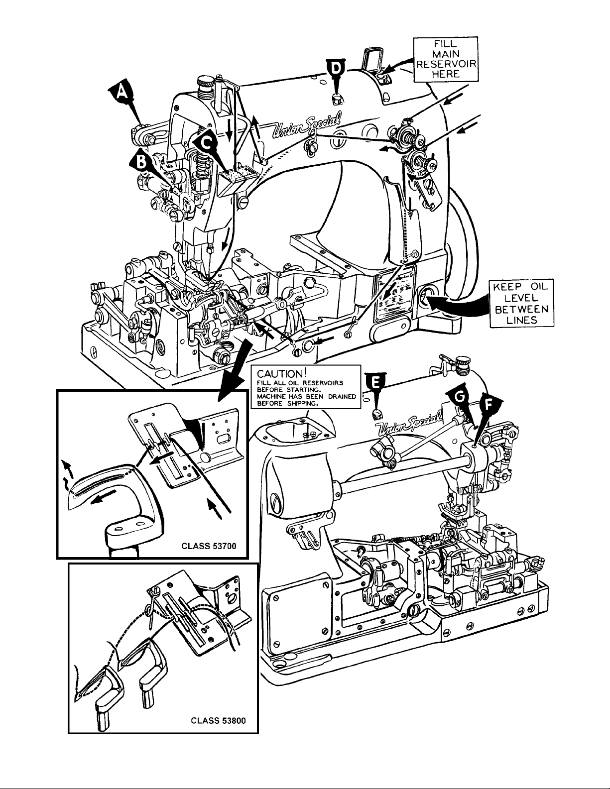
Fig. 1
7
Page 8
SYNCHRONIZING LOOPER AND NEEDLE MOTIONS
Check the synchronization of the looper and needle motions, using gauge No. T34 and plate No.
21227AD as follows:
Insert the pin, which is included with the gauge, in the looper rocker for 2 needle machine use right
looper. Place the gauge plate on the throat plate seat using the throatplate screws for attaching. Place
the indicator portion of the gauge in the needle thread take-up wire hole with the pointer to the right,
but do not tighten the set screw at this time. Turn the handwheel in the operating direction until the pin
in the looper rocker contacts the edge of the gauge plate and set the indicator so that the left end of
the pointer rests against the top of the needle bar and the right end of the pointer rests at “O”. Tighten
the set screw and note indicator reading. Turn the handwheel in the reverse direction until the pin again
contacts the plate. If the motions are in synchronization, the pointer of the indicator will return to the
same reading. A variation of one graduation on the scale is allowable. If the reading is higher on the
scale when the handwheel is turned in the operating direction, the looper drive lever rocker will have to
be moved to the rear. If the reading is lower, the rocker will have to be moved to the front.
NOTE: If gauge No. 21227AD is not available, synchronization may be checked as follows:
Insert the looper in the looper rocker and turn the handwheel in the operating direction until the point of
the looper, moving to the left, is even with the left side of the needle. Note the height of the eye of the
needle with respect to the looper point, then turn handwheel in the reverse direction until the looper
point again moves to the left and is even with the left side of the needle. If the motions synchronize, the
height of the eye of the needle with respect to the looper point will be the same. A variation of .005
inch is allowable. If the distance from the eye of the needle to the point of the looper is greater when
the handwheel is turned in the operating direction, move the looper drive lever rocker to the rear.
Moving it in the opposite direction acts the reverse. Moving of the looper drive lever rocker is accomplished as follows:
Remove the cloth plate, throat plate support, oil reservoir top
cover and loosen the screws in the looper drive eccentric mechanism and move the eccentric as far to the right as it will go. Drive
the rear bushing to the front or the middle bushing to the rear, as
required. CAUTION: To avoid distorting the parts, remove the plug
screw in the bed behind the rear bushing before driving to the
front and place a horse shoe shaped metal washer approximately
1/16 inch thick between the looper drive lever and adjacent
bushing when driving the bushing to the rear. Correctly reposition
the looper drive eccentric mechanism (per spot screws) and
tighten all screws securely.
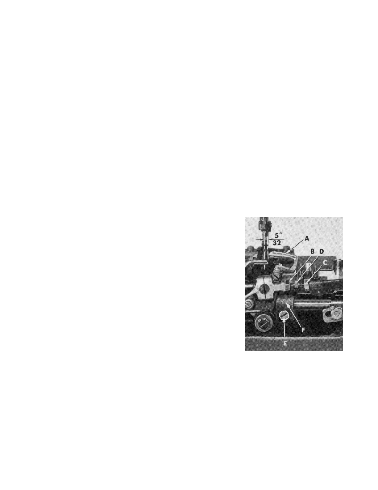
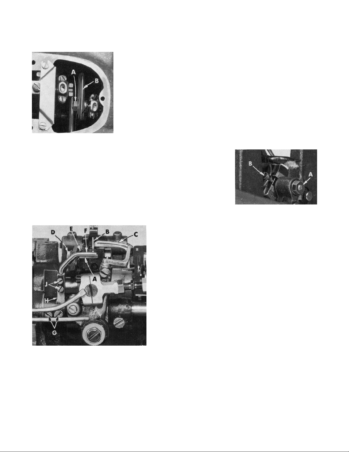
SETTING THE LOOPER
Insert a new needle, type and size as specified, with spot or scarf
to the rear. With the looper (A, Fig. 2) at its farthest position to the
right, its point should be 5/32 inch from the centerline of the
needle. If adjustment is required, loosen nut (B) (it has a left hand
thread) and nut (C) on connecting rod (D) and turn the connecting rod forward or backward to obtain the 5/32 inch dimension
(Fig. 2). Looper gauge No. 21225-5/32 can be used advantageously in making this adjustment. Retighten both nuts, first nut (C),
then nut (B). Make sure the left ball joint is in vertical position and
does not bind after adjustment.
NOTE: For 2 needle 53800, looper gauge should be set using the left needle and looper.
Fig. 2
8
Page 9
SETTING THE LOOPER (CONTINUED)
The looper is set correctly front to back, as it moves to the left behind the needle, when its point passes
as close as possible without contacting the needle (.001-.002). If adjustment is necessary, loosen screw
(E, Fig. 2) in looper rock shaft arm (F), reposition looper as required and retighten screw (E).
Fig. 4
SETTING HEIGHT OF NEEDLE BAR
The height of the needle is correct when the top of its eye is
1/64 inch below the underside of the looper, when the
Fig. 3
looper point is flush with the left side of the needle. If adjustment is necessary, loosen screw (A, Fig. 3) and move needle
bar (B) up or down as required and retighten screw (A).
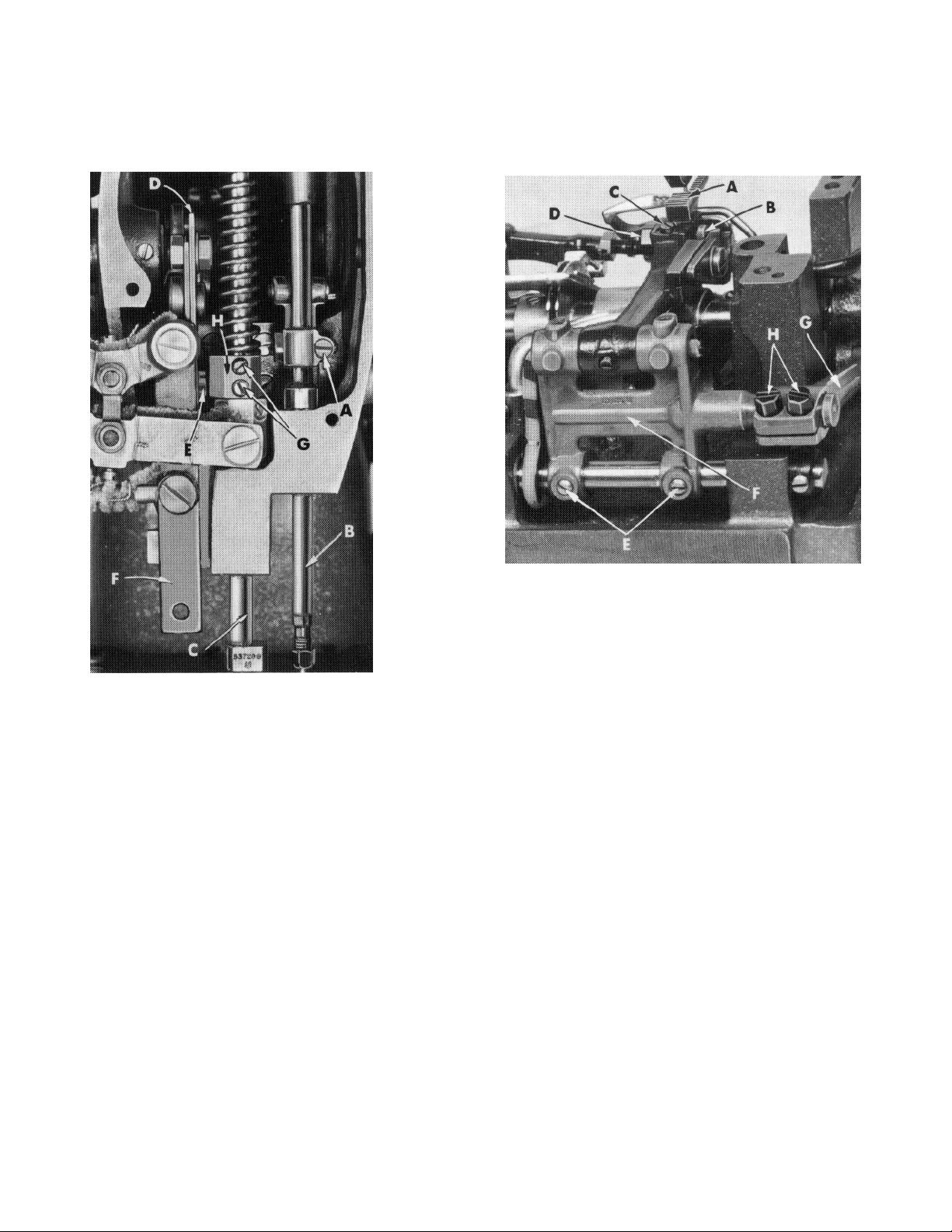
SETTING THE FEED DOG
Set the feed dog (A, Fig. 4) in the throat plate so there is equal clearance on all sides. See that the tips
of the teeth extend 1/2 to 1 full tooth above the throat plate and are parallel with the throat plate at
high point of travel. Height can be set by loosening feed dog attaching screw (B) and adjusting feed
dog supporting screw (C). Parallelism can be set by loosening nut (D) and rotating feed dog holder
adjusting screw (A, Fig. 5), as required and retighten nut. Side clearance can be set by loosening screws
(E, Fig. 4) and moving feed rocker (F) to the right or left, as required.
NOTE: Whenever the feed rocker has been moved, always check to assure that the feed rocker arm
(G) does not bind.
End clearance can be set by loosening screws (H) in the feed rocker arm (G) and moving feed rocker
(F) forward or backward as required.
9
Page 10
INITIAL SETTINGS OF UPPER RUNNING FEED MECHANISM
The top feed eccentric assembly should be located on the main shaft so that the first screw in the
eccentric will be in a perpendicular position to the mainshaft when the needle bar has risen 1/2"
(12.7 mm) from the bottom of its stroke, with the handwheel turned in the operating direction.
NOTE: Eccentric may need to be advanced or retarded to obtain proper feeding between top and
bottom feeds.
NOTE: The next two paragraphs refer to the maximum height setting of the top feed mechanism
which can be lowered later to suit sewing conditions.
Turn handwheel in the
operating direction until the
needle bar is at the bottom
of its stroke. Loosen nut (B,
Fig.6), and move upper feed
lift driving lever (A) so that
the teeth of the upper feed
dog is 5/32" (7.9mm) for style
53700B and 3/16" to 13/64"
Fig. 5
the throat plate. Then tighten nut (B) securely.
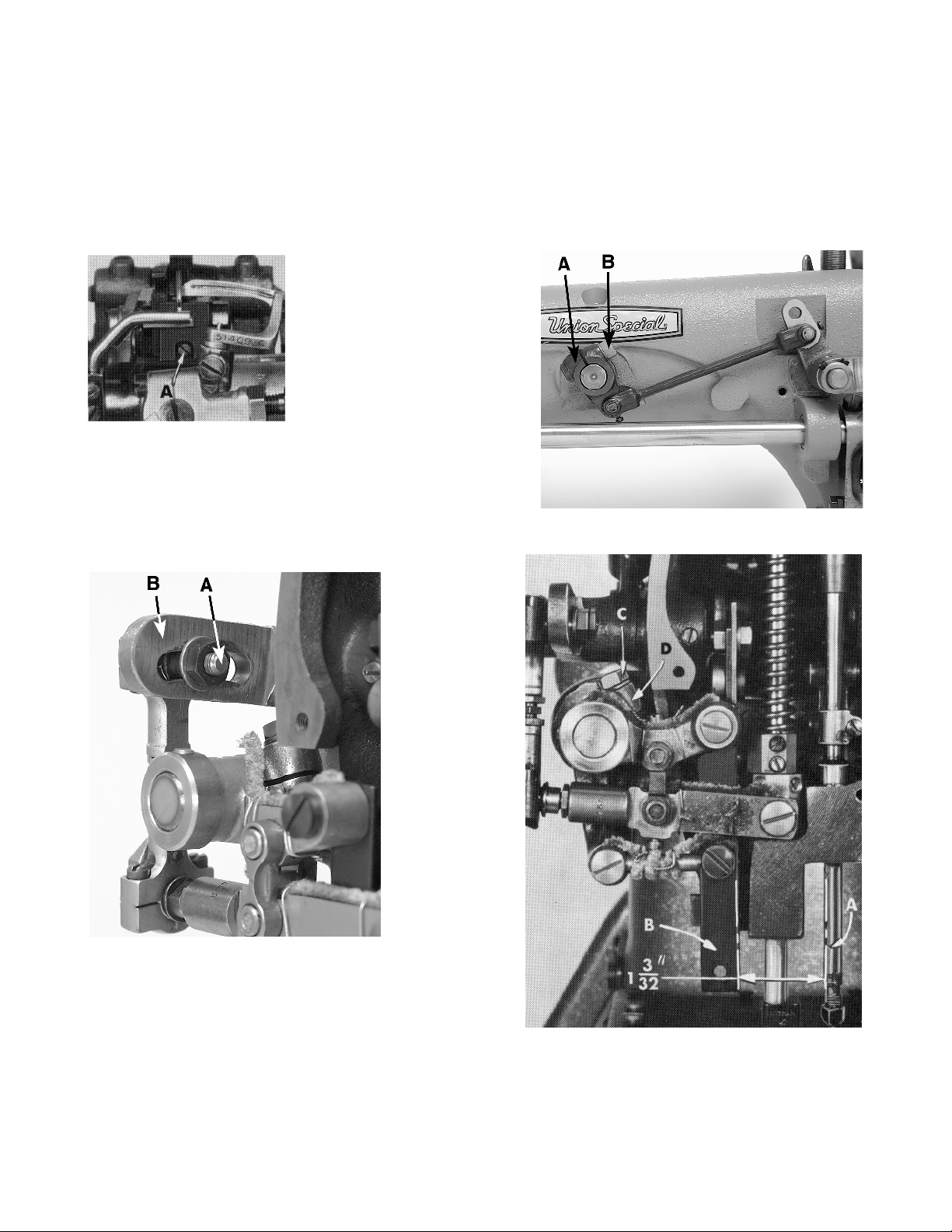
The bell crank lever ball joint (A, Fig. 7) should be in the
center of the upper feed bell crank lever (B). The ball joint
may need to be moved slightly to meet sewing conditions.
(4.8 to 5.2mm) for style
53800B, above the top of
Fig. 6
Fig. 7
As the needle bar just begins to rise from the bottom of
its stroke, the distance between the rear of the needle
bar (A, Fig.8) and the front of the upper feed bar (B)
should be 1 3/32 inch (Fig. 8). Adjustment can be
made by loosening screw (C) in the upper feed driving
lever (D) and moving it forward or rearward as required and retighten screw (C).
10
Fig. 8
Page 11
INITIAL SETTINGS OF UPPER RUNNING FEED MECHANISM (CONTINUED)
Synchronizing the upper feed with the lower feed can be accomplished by loosening nut (A, Fig. 9) and
moving the ball stud in the upper feed driving shaft segment lever (B). Retighten nut.
CHANGING STITCH LENGTH
Set the stitch to the required length. This is accomplished by loosening locknut (A, Fig. 10) (it has a left hand thread) and turning the
stitch adjusting screw (B). Turning screw (B) clockwise shortens the
stitch and turning it in a counterclockwise direction lengthens the
stitch.
NOTE: Any change in stitch length will necessitate a correspond-
ing change in the rear needle guard setting and also
synchronization of the upper running feed mechanism as
described previously.
Fig. 9
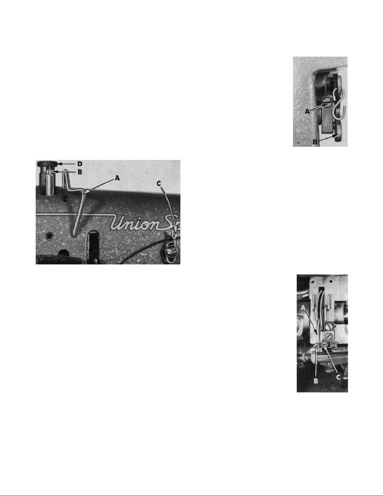
Set the rear needle guard (A, Fig. 11) horizontally so that it barely
contact the rear of the needle (B) when at its most forward point of
travel. It should be set as low as possible, yet have its guarding surface
in contact with the needle, until the point of the looper (C), moving to
the left, is even with the needle. To move needle guard forward or
backward, merely loosen screw (D), move needle guard as required
and retighten screw (D) To raise or lower the needle guard, loosen
screw (D; and turn screw (E) clockwise to lower or counterclockwise to
raise. Retighten screw (D) after guard is properly set.
SETTING THE REAR NEEDLE GUARD
SETTING FRONT NEEDLE GUARD
Set the front needle guard (F, Fig. 11) so that it barely
contacts the needle (B) until the point of the looper (C),
moving to the left, is just past the left side of the needle.
The looper may brush, but not pick at the needle. The front
needle guard should beset as low as possible to meet this
condition yet not contact the rear needle guard or looper
at any time. To move needle guard forward or rearward,
loosen screws (G), rotate needle guard holder (H) as
required and retighten screws (G). To raise, lower or rotate
needle guard, loosen screws (J), reposition as necessary
and retighten screws after guard is properly set.
Fig. 10
Fig. 11
THREAD TENSION RELEASE
The thread tension release is set correctly when it begins
to function as the presser foot is raised to within 1/8 inch of
the end of its travel and is entirely released when the
presser foot has reached its highest position.
11
Page 12
THREAD TENSION RELEASE (CONTINUED)
If adjustmentis needed, loosen tension release lever screw (A, Fig. 12), located at the back of the
machine and move tension disc separator as required. Retighten screw. After adjustment there should
be no binding at any point.
SETTING HEIGHT OF PRESSER BAR
The height of the presser bar (C, Fig. 3) is set correctly if it is possible to remove
the presser foot when the foot lifter lever (B, Fig. 12) is fully depressed.
If adjustment is necessary, turnhandwheel in operating direction until the needle
bar is in the low position. Loosen screws (G, Fig. 3), then, while holding presser foot
down on the throat plate surface, pry up presserbar connectionand guide(H) with
ascrewdriver to obtain the 1/16 inch setting and retighten screws.
Fig. 12
THREADING
Draw the looper and needle threads into the machine and start operating on a piece of fabric.
Refer to threading diagram (Fig. 1) for manner of
threading these machines.
SETTING NEEDLE THREAD TAKE-UP WIRE AND
FRAME EYELET
Set the needle thread take-up wire (A, Fig. 13) so
that its upper surface is even with the top of the
hole in the needle bar thread eyelet (B) when the
needle bar is at the bottom of its stroke. Lower this
setting for a smaller needle thread loop or raise it
for a larger loop.
Fig. 13
Set the needle thread frame eyelet (C, Fig. 13) perpendicular to the machine base
and 1/4" above the mounting screw. Lower if more needle thread is desired in the
stitch or raise for less.
SETTING LOOPER THREAD TAKE-UP
The looper thread retainer finger (A, Fig. 14) should be set so that the looper thread
is cast-off just after the eye of the needle comes up out of the material. Coordinated positioning can be acquired by loosening screws (B and C). After looper
thread retainer finger has been properly set, retighten screws.
PRESSER FOOT PRESSURE
Regulate the presser spring regulating screw (D, Fig. 13) so that it exerts only
enough pressure on the presser foot to feed the work uniformly when a slight
tension is placed on the fabric. Turning it clockwise increases the pressure, counterclockwise acts the reverse.
Fig. 14
12
Page 13

EXPLODED VIEWS
AND
DESCRIPTION OF PARTS
13
Page 14

14
Page 15

MAIN FRAME, MISCELLANEOUS COVERS AND PLATES
Ref.
No.
1.
2.
3.
4.
5.
6.
7.
8.
9.
10.
11.
12.
13.
14.
15.
16.
17.
18.
19.
20.
21.
22.
23.
24.
25.
26.
27.
28.
29.
30.
31.
32.
33.
34.
35.
36.
37.
38.
39.
40.
41.
42.
43.
44.
45.
46.
47.
48.
49.
*
*
Part No.
22585A
22524
53782B
51382B
22839C
51281P207
51281AC
22760A
35772H
22845B
80
53701
22570
22839
294
53782E
53780
51280J
51280K
51270B
95
GR-96122A
53724A
53824A18
21396BN
21396AG
22517B
22889A
53758
20
22848
95
35731A
22513D
22528
53753G
605A
53780A
12934A
22539H
22889D
158B
136
53780B
52A
98A
51291A
98A
50-648BLK
20
22848
Description
Screw ............................................................................................................
Screw ............................................................................................................
Oil Reservoir Top Cover .................................................................................
Gasket ..........................................................................................................
Screw ............................................................................................................
Cloth Plate Cover .........................................................................................
Cloth Plate Cover Spring ...............................................................................
Screw ............................................................................................................
Spring Washer ...............................................................................................
Screw ............................................................................................................
Screw ............................................................................................................
Cloth Plate ....................................................................................................
Screw ............................................................................................................
Screw ............................................................................................................
Screw ............................................................................................................
Head Cover ..................................................................................................
Throat Plate Support .....................................................................................
Dowel Pin, lower .....................................................................................
Dowel Pin, upper ....................................................................................
Needle Thread Pull-off Wire ..........................................................................
Screw ............................................................................................................
Lock Washer .................................................................................................
Throat Plate, for Style 53700B ........................................................................
Throat Plate, for Style 53800B ........................................................................
Needle Thread Lubricator ............................................................................
Lubricating Felt .......................................................................................
Screw ............................................................................................................
Adapter Screw ..............................................................................................
Frame Thread Eyelet .....................................................................................
Washer ..........................................................................................................
Screw ............................................................................................................
Set Screw, for upper feed bell crank lever shaft ............................................
Presser Bar Connection Guide Plate .............................................................
Screw ............................................................................................................
Screw ............................................................................................................
Thrust Bracket ...............................................................................................
Screw ............................................................................................................
Throat Plate Support Rod ..............................................................................
Nut ................................................................................................................
Plug Screw ....................................................................................................
Plug Screw ....................................................................................................
Frame Thread Eyelet for Style 53800B ............................................................
Screw ............................................................................................................
Throat Plate Support Rod Bracket .................................................................
Frame Thread Eyelet, for Style 53700B ...........................................................
Screw ............................................................................................................
Looper Thread Guard ...................................................................................
Screw, for looper thread guard ....................................................................
Lucite Oil Guage ...........................................................................................
Washer, for 22848 ..........................................................................................
Screw, for 51282AH .......................................................................................
Amt.
Req.
2
7
1
1
2
1
1
3
3
1
3
1
2
3
3
1
1
2
2
1
1
1
1
1
1
2
1
1
1
1
1
1
2
4
1
1
1
1
1
1
1
3
1
1
3
3
1
1
1
3
3
15
Page 16

16
Page 17

BUSHINGS, OIL TUBES, WICKS AND MISCELLANEOUS COVERS
Ref.
No.
1.
2.
3.
4.
5.
6.
7.
8.
9.
10.
11.
12.
13.
14.
15.
16.
17.
18.
19.
20.
21.
22.
23.
24.
25.
26.
27.
28.
29.
30.
31.
32.
33.
34.
35.
Part No.
22541B
52882AD
39582L
52882AC
50-789BLK
52882AA
90
90
52882P
52882Y
22539D
21375BQ
93
52891B
52890C
51242C
21657X
51242R
52944U
52883R
53790A
52894AB
52894AC
53750A
53750B
80689D
51254D
53788A
52890C
51254C
51290T
90
22560B
52894AK
52944T
Description
Screw ............................................................................................................
Crank Chamber Cover, upper ......................................................................
Oil Cap ...................................................................................................
Oil Cap Torsion Spring .............................................................................
Oil Cap Hinge Pin ....................................................................................
Drip Plate ................................................................................................
Screw .....................................................................................................
Screw ............................................................................................................
Gasket ..........................................................................................................
Baffle Plate ...................................................................................................
Plug Screw ....................................................................................................
Belt Guard ....................................................................................................
Screw ............................................................................................................
Main Shaft Bushing Housing, includes bushing ..............................................
Main Shaft Bushing, left and right ..................................................................
Looper Drive Lever Shaft Bushing, front .........................................................
Tension Release Lever Shaft Bushing .............................................................
Looper Drive Lever Shaft Bushing, middle .....................................................
Looper Rock Shaft Bushing, right ...................................................................
Presser Foot Lifter Lever Bushing ....................................................................
Upper Running Feed Drive Rock Shaft Bushing, right .....................................
Oil Tube Holder .............................................................................................
Oil Tube, for feed lift and looper avoid eccentric .........................................
Needle Lever Bushing, front ..........................................................................
Needle Lever Bushing, rear ...........................................................................
Oil Cup ..........................................................................................................
Needle Bar Bushing, lower ............................................................................
Presser Bar Bushing, lower .............................................................................
Upper Running Feed Drive Rock Shaft Bushing, left .......................................
Needle Bar Bushing, upper ...........................................................................
Main Shaft Bushing, middle ...........................................................................
Screw ............................................................................................................
Screw ............................................................................................................
Oil Tube, for looper rocker and left ball joint ..................................................
Looper Rock Shaft Bushing, left .....................................................................
Amt.
Req.
3
1
1
1
1
1
2
2
1
1
1
1
2
1
2
1
1
1
1
1
1
1
1
1
1
2
1
1
1
1
1
1
1
1
1
36. thru 71. See Following page
17
Page 18

18
Page 19

BUSHINGS, OIL TUBES, WICKS AND MISCELLANEOUS COVERS CONTINUED
Ref.
No.
Part No.
1. thru 35. See Previous page
660-136
36.
258A
37.
52936
38.
51242S
39.
52882L
40.
52882AT
41.
52882AE
42.
52882AS
43.
22548
44.
22848
45.
22733B
46.
41394A
47.
22883A
48.
643-127BLK
49.
51493BQ
50.
531
51.
51493AG
52.
51493D
53.
51493BR
54.
22569B
55.
51493AH
56.
51493BH
57.
51493BJ
58.
22823A
59.
22823B
60.
51493AY
61.
51295A
62.
22571A
63.
666-111
64.
666-179
65.
666-118
66.
666-65
67.
35178D
68.
666-114
69.
22889C
70.
51493BK
71.
22848
*
51282AH
*
20
*
Description
Feed Crank Link Oil Tube ..............................................................................
Nut .........................................................................................................
Feed Rocker Shaft Bushing ...........................................................................
Looper Drive Lever Shaft Bushing, rear .........................................................
Oil Reservoir Back Cover ..............................................................................
Gasket ..........................................................................................................
Crank Chamber Cover, lower ......................................................................
Gasket ..........................................................................................................
Screw ...........................................................................................................
Screw ...........................................................................................................
Screw ...........................................................................................................
Gasket ..........................................................................................................
Plug Screw ....................................................................................................
Gasket ..........................................................................................................
Oil Pump Driven Gear ...................................................................................
Screw .....................................................................................................
Oil Pump Housing .........................................................................................
Oil Pump Driving Shaft ..................................................................................
Oil Pump Driving Shaft Gear .........................................................................
Screw ...........................................................................................................
OIl Pump Housing Cover ...............................................................................
Filter Cap Assembly ......................................................................................
Washer, rubber ......................................................................................
Screw ...........................................................................................................
Screw ...........................................................................................................
Base Plate ....................................................................................................
Mounting Isolator .........................................................................................
Plug Screw ....................................................................................................
Oil Wick ........................................................................................................
Wedge Pin ....................................................................................................
Oil Wick ........................................................................................................
Oil Wick ........................................................................................................
Spring ...........................................................................................................
Oil Wick ........................................................................................................
Plug Screw ....................................................................................................
Lint Filter Screen ...........................................................................................
Screw, for 51282AH ......................................................................................
Oil Shield, end and back ..............................................................................
Washer .........................................................................................................
Amt.
Req.
1
1
2
1
1
1
1
1
4
9
1
2
1
1
1
2
1
1
2
3
1
1
1
2
1
1
4
15
2
2
2
2
4
2
2
1
2
1
2
19
Page 20

20
Page 21

CRANKSHAFT AND UPPER FEED DRIVING ROCK SHAFT PARTS
Ref.
No.
1.
2.
3.
4.
5.
6.
7.
8.
9.
10.
11.
12.
13.
14.
15.
16.
17.
18.
19.
20.
21.
22.
23.
24.
25.
26.
27.
28.
29.
30.
31.
32.
33.
34.
35.
36.
37.
38.
39.
40.
41.
42.
43.
44.
45.
46.
47.
48.
49.
50.
51.
52.
53.
54.
Part No.
51321G
22894H
22894E
22569B
56390E
660-202
9660B
98
666-53
29126BJ
22587
22894C
15430D
53716
29476DT
22559E
51216
51493BP
22560B
51242P
22729
51243U
29105Q
22559B
22894D
22894C
22559A
52841G
51242Y
51242L
52841J
51242M
51242M
22852A
81
12982
269
22747
41255B
52854
22729C
454A
258
53752
22811
80630C
660-202
52849C
95
52849
29066X
97A
51216N
15430D
Description
"V" Belt Handwheel .......................................................................................
Spot Screw, for round and "V" belt handwheel .......................................
Set Screw, for round and "V" belt handwheel .........................................
Screw, for housing ........................................................................................
Crankshaft Bearing Housing Gasket .............................................................
"O" Ring, for pulley ........................................................................................
Crankshaft Thrust Collar ...............................................................................
Set Screw ...............................................................................................
Lubricating Felt ............................................................................................
Upper Running Feed Drive Eccentric Assembly ...........................................
Bearing Cap Screw ................................................................................
Eccentric Set Screw ...............................................................................
Nut, right thread ...........................................................................................
Top Feed Driving Connecting Rod ...............................................................
Crankshaft Assembly ...................................................................................
Bearing Cap Screw ................................................................................
Needle Lever Connecting Rod ....................................................................
Pump Driving Gear .......................................................................................
Screw .....................................................................................................
Looper Drive Lever Shaft ..............................................................................
Screw ...........................................................................................................
Ball Stud Guide Fork ......................................................................................
Looper Drive Eccentric Assembly .................................................................
Bearing Cap Screw, upper .....................................................................
Eccentric Spot Screw .............................................................................
Eccentric Set Screw ...............................................................................
Bearing Cap Screw, lower ......................................................................
Locking Stud .................................................................................................
Looper Drive Lever Rocker ...........................................................................
Thrust Washer ...............................................................................................
Nut ...............................................................................................................
Washer .........................................................................................................
Washer .........................................................................................................
Clamp Screw ................................................................................................
Spot Screw ...................................................................................................
Lock Nut .......................................................................................................
Nut, left thread .............................................................................................
Screw ...........................................................................................................
Ball Stud Guide Fork ......................................................................................
Upper Running Feed Drive Connecting Rod Ball Joint Assembly ..................
Bearing Cap Screw ................................................................................
Washer .........................................................................................................
Nut ...............................................................................................................
Upper Feed Driving Shaft Segment Lever .....................................................
Clamp Screw .........................................................................................
Nut, left thread .............................................................................................
Oil Seal Ring ..................................................................................................
Upper Running Feed Drive Rock Shaft Thrust Collar ......................................
Set Screw ...............................................................................................
Upper Running Feed Drive Rock Shaft ..........................................................
Needle Lever Connecting Rod Ball Joint ......................................................
Bearing Cap Screw ................................................................................
Washer............................................................................................................
Nut...................................................................................................................
Amt.
Req.
1
1
1
3
1
1
1
2
1
1
2
2
2
1
1
2
1
1
2
1
2
2
1
2
2
3
2
1
1
2
1
1
1
1
1
1
1
1
1
1
2
1
1
1
1
1
1
1
2
1
1
2
1
1
21
Page 22

22
Page 23

FEED ROCKER SHAFT, MAIN SHAFT AND LOOPER ROCKER FRAME ROCKER SHAFT PARTS
Ref.
No.
1.
2.
3.
4.
5.
6.
7.
8.
9.
10.
11.
12.
13.
14.
15.
16.
17.
18.
19.
20.
21.
22.
23.
24.
25.
26.
27.
28.
29.
30.
31.
32.
33.
34.
35.
36.
37.
38.
39.
40.
41.
42.
43.
44.
45.
46.
47.
48.
49.
50.
51.
52.
53.
54.
55.
56.
57.
58.
Part No.
8
51134P
51134R
51134C
51235
98
482
98
29476RF
51235X
51235G
22519C
77
51054A
666-149
51236M
-269
20
53722
22768
51236B
82
51236G
29476BJ
22894D
51145
PI18
666-82
51236J
77
29476AR
22894D
51145
PI18
666-82
51236J
77
51423C
96
22580D
55244G
51244N
51216N
18
51244L
52470
51244B
22519H
51144
51244
96
98
52444B
52825D
33174B
77
51325
Description
Feed Rocker Shaft ........................................................................................
Lubricating Felt ............................................................................................
Lubricating Felt Guard .................................................................................
Feed Bar Shaft ..............................................................................................
Feed Rocker .................................................................................................
Screw .....................................................................................................
Feed Rocker Shaft Collar .............................................................................
Screw .....................................................................................................
Feed Rocker Arm and Link Assembly ............................................................
Feed Rocker Arm ...................................................................................
Washer ............................................................................................
Screw ..............................................................................................
Set Screw ...............................................................................................
Feed Crank Link Pin ................................................................................
Lubricating Felt ...............................................................................
Feed Crank Link Assembly .....................................................................
Ferrule (Not sold separately)...........................................................
Nut, left thread .............................................................................................
Washer .........................................................................................................
Mainshaft .....................................................................................................
Screw ...........................................................................................................
Feed Crank Stud Cap ...................................................................................
Stitch Regulating Screw ...............................................................................
Feed Crank Stud ..........................................................................................
Feed Lift Eccentric Assembly ...............................................................
Spot Screw .............................................................................................
Feed Lift and Looper Avoid Eccentric Link .............................................
Pin ..........................................................................................................
Lubricating Felt ......................................................................................
Link Pin ...................................................................................................
Screw .....................................................................................................
Looper Avoid Eccentric Assembly ...............................................................
Spot Screw .............................................................................................
Feed Lift and Looper Avoid Eccentric Link .............................................
Pin ..........................................................................................................
Lubricating Felt ......................................................................................
Link Pin ...................................................................................................
Screw .....................................................................................................
Take-up ........................................................................................................
Time Spot Screw .....................................................................................
Set Screw ...............................................................................................
Locking Stud ................................................................................................
Looper Rock Shaft Collar .............................................................................
Washer .........................................................................................................
Nut ...............................................................................................................
Thrust Washer ...............................................................................................
Stop, for looper connecting rod ...................................................................
Looper Rock Shaft Arm .................................................................................
Screw .....................................................................................................
Looper Rock Shaft ........................................................................................
Looper Rocker Frame, for Style 53800B ........................................................
Spot Screw ...................................................................................................
Set Screw .....................................................................................................
Looper Rocker Frame, for Stle 53700B ..........................................................
Looper Needle Guard Holder, for Style 53700B ............................................
Screw .....................................................................................................
Screw .....................................................................................................
Looper Needle Guard, for Style 53700B .......................................................
Amt.
Req.
1
1
1
1
1
2
2
2
1
1
2
2
2
1
1
1
1
1
1
1
2
1
1
1
1
1
1
1
1
1
1
1
1
1
1
1
1
1
1
1
1
1
1
1
1
2
1
1
1
1
1
1
1
1
1
2
2
1
23
Page 24

24
Page 25

FEED BAR, LOOPER ROCKER AND CONECTING ROD PARTS
Ref.
No.
1.
2.
3.
4.
5.
6.
7.
8.
9.
10.
11.
12.
13.
14.
15.
16.
17.
18.
19.
20.
21.
22.
23.
24.
25.
26.
27.
28.
29.
30.
31.
32.
33.
34.
35.
36.
37.
38.
39.
40.
41.
42.
43.
44.
45.
46.
47.
48.
49.
50.
51.
52.
53.
Part No.
51134X
22560B
56334E
538
22863
6042A
258
77
22834
53705A
22528
51225
53825
22801
51225W
22585B
53805A
53825
18
52841A
22729C
269
51240D
51241K
56341G
22729C
50-458BLK
12538
53710
73A
51409C
1740
21211
73
73
29192
51213
51745
15465F
22894W
258
22829
51246
51508M18
51909C
29192D
51513
51745
15465F
22894W
258
22829
51242W
22811B
22894H
Description
Feed Bar .......................................................................................................
Set Screw ...............................................................................................
Feed Dog Holder ....................................................................................
Feed Dog Height Adjusting Screw ..........................................................
Feed Dog Holder Adjusting Screw ..........................................................
Washer ...................................................................................................
Feed Dog Holder Nut .............................................................................
Screw ...........................................................................................................
Needle Guard Adjusting Screw ....................................................................
Lower Feed Dog, for Style 53700B .................................................................
Screw ...........................................................................................................
Needle Guard, for Style 53700B ....................................................................
Needle Guard, for Style 53800B ....................................................................
Needle Guard Guide Screw ..................................................................
Washer .........................................................................................................
Screw ...........................................................................................................
Lower Feed Dog, for Style 53800B .................................................................
Needle Guard, for Style 53800B ....................................................................
Nut ...............................................................................................................
Looper Connecting Rod Ball Joint, left .........................................................
Bearing Cap Screw ................................................................................
Nut, left thread .............................................................................................
Looper Connecting Rod, 1 11/32 inches long ..............................................
Looper Connecting Rod Ball Joint, right .......................................................
Spring .....................................................................................................
Bearing Cap Screw ................................................................................
Spring Pin ...............................................................................................
Nut ...............................................................................................................
Looper Needle Guard, for 53700B older models ..........................................
Screw ...........................................................................................................
Looper, for Style 53700B ...............................................................................
Looper Needle Guard Pin ......................................................................
Looper Collar, for Style 53700B .....................................................................
Screw, for Style 53700B .................................................................................
Screw, for Style 53800B .................................................................................
Looper Rocker Assembly, for Style 53700B ....................................................
Looper Rocker .......................................................................................
Looper Rocker Cone Stud ......................................................................
Looper Rocker Cone ..............................................................................
Set Screw .........................................................................................
Lock Nut .................................................................................................
Lock Nut Screw ......................................................................................
Nut ...............................................................................................................
Looper, front, for Style 53800B ......................................................................
Looper, rear, for Style 53800B .......................................................................
Looper Rocker Assembly, for Style 53800B ....................................................
Looper Rocker .......................................................................................
Looper Rocker Cone Stud ......................................................................
Looper Rocker Cone ..............................................................................
Set Screw .........................................................................................
Lock Nut .................................................................................................
Lock Nut Screw ......................................................................................
Looper Drive Lever .......................................................................................
Clamp Screw .........................................................................................
Spot Screw ...................................................................................................
Amt.
Req.
1
1
1
1
1
1
1
1
1
1
1
1
1
1
1
1
1
1
2
1
2
1
1
1
1
2
1
1
1
1
1
1
1
1
2
1
1
1
1
2
1
1
1
1
1
1
1
1
1
2
1
1
1
1
1
25
Page 26

26
Page 27

UPPER FEED DRIVE, NEEDLE BAR DRIVE AND PRESSER BAR PARTS
Ref.
No.
1.
2.
3.
4.
5.
6.
7.
8.
9.
10.
11.
12.
13.
14.
15.
16.
17.
18.
19.
20.
21.
22.
23.
24.
25.
26.
27.
28.
29.
30.
31.
32.
33.
34.
Part No.
53753H
22585S
9937
51770-88
51771
22773A
22773B
22764A
53783D
531
53755A
22787D
J87J
56354D
22598D
9660B
98
53752F
J87J
51054A
666-149
53752D
627A
80557
12934A
53788B
53783C
22560B
41071G
33174B
52889A
53787
22768
56358
Description
Upper Running Feed Bar ...............................................................................
Screw, for upper feed dog ...........................................................................
Nut ...............................................................................................................
Upper Running Feed Bar Spacing Link ..........................................................
Upper Running Feed Bar Link Bushing ...........................................................
Screw ...........................................................................................................
Screw ...........................................................................................................
Screw ...........................................................................................................
Presser Bar Connection Block .......................................................................
Screw ...........................................................................................................
Upper Running Feed Foot Lifter Link ..............................................................
Screw ...........................................................................................................
Screw ...........................................................................................................
Connection Link ...........................................................................................
Screw ...........................................................................................................
Upper Running Feed Drive Rock Shaft Collar ................................................
Screw .....................................................................................................
Upper Running Feed Lifter Drive Link ............................................................
Screw ...........................................................................................................
Link Pin ..........................................................................................................
Lubricating Felt ......................................................................................
Upper Running Feed Driving Lever ...............................................................
Clamp Screw .........................................................................................
Washer ...................................................................................................
Nut ...............................................................................................................
Presser Bar ....................................................................................................
Presser Bar Connection and Guide ..............................................................
Screw .....................................................................................................
Nut ...............................................................................................................
Screw ...........................................................................................................
Presser Bar Bushing, upper and presser spring regulator ..............................
Presser Spring ...............................................................................................
Scew ............................................................................................................
Needle Bar Thread Eyelet, for Style 53700B ...................................................
Amt.
Req.
1
1
3
1
2
1
1
1
1
1
1
1
1
1
1
1
2
1
1
2
1
1
1
1
1
1
1
2
1
1
1
1
1
1
35. thru 67. See Following page
27
Page 28

28
Page 29

UPPER FEED DRIVE, NEEDLE BAR DRIVE AND PRESSER BAR PARTS CONTINUED
Ref.
No.
Part No.
1. thru 34. See Previous page
35.
652C9
36.
29348AW
37.
52336A
38.
666-149
39.
77
40.
53715A
41.
56350B
42.
51216N
42A
43.
44.
45.
46.
47.
48.
49.
50.
51.
52.
53.
54.
55.
56.
57.
58.
59.
60.
61.
62.
63.
64.
65.
66.
67.
15430D
56354D
22564
51254K
22562A
22591A
HA81
22768
56358A
51217
56
53720
78
53726
56458
56458A
56517B18
50J16
98
7018E5
7040-6
187B
89
53820-18
88
53826
Description
Needle Bar Eyelet Lock Washer ....................................................................
Needle Lever Assembly ...............................................................................
Screw ...........................................................................................................
Screw ...........................................................................................................
Screw ...........................................................................................................
Needle Lever Thread Eyelet, for Style 53700B ...............................................
Needle Bar, for Style 53700B .........................................................................
Needle Clamp Nut, for Style 53700B .............................................................
Presser Foot, for Style 53700B ........................................................................
Upper Feed Dog, for Style 53700B ................................................................
Needle Lever Thread Eyelet, for Style 53800B ...............................................
Needle Bar Thread Eyelet, for Style 53800B ..................................................
Needle Bar, for Style 53800B .........................................................................
Set Screw, for needles for Style 53800B .........................................................
Needle Bar Head, for Style 53800B ...............................................................
Screw, for Style 53800B .................................................................................
Presser Foot, for Style 53800B ........................................................................
Upper Feed Dog, for Style 53800B ................................................................
Needle Bar Connection Link Pin ............................................................
Lubricating Felt ...............................................................................
Screw .....................................................................................................
Needle Lever .........................................................................................
Bushing ............................................................................................
Washer ...................................................................................................
Nut...........................................................................................................
Needle Bar Connection Link ..................................................................
Screw .....................................................................................................
Needle Bar Connection .........................................................................
Screw ..............................................................................................
Screw, for Style 53700B ..........................................................................
Needle Stop Pin .....................................................................................
Thread Guide ........................................................................................
Thread Guide Screw ..............................................................................
Screw .....................................................................................................
Amt.
Req.
1
1
2
1
1
1
1
1
1
1
1
1
1
1
1
1
1
1
1
1
2
1
1
1
1
1
2
1
1
1
1
1
2
1
29
Page 30

30
Page 31

UPPER FEED LIFT AND PRESSER FOOT LIFTER PARTS
Ref.
No.
1.
2.
3.
4.
5.
6.
7.
8.
9.
10.
11.
12.
13.
14.
15.
16.
17.
18.
19.
20.
21.
22.
23.
24.
25.
26.
27.
28.
29.
30.
31.
32.
33.
34.
35.
36.
37.
38.
39.
40.
41.
42.
43.
44.
45.
Part No.
53750
53754
55235D
6042A
55235E
77
51236J
53754A
53754F
51242L
53754D
482C
22894C
22768
18
15037A
21657E
53754G
22729C
15037A
43242N
43242P
43241D
22729C
41255B
22747
22882
53783R
53783P
20
18
240
9255
53783L
52883S
22557B
56383AB
53783N
22537
53783T
21657Y
402
22596
21657W
660-207
Description
Needle Lever and Upper Feed Lift Driving Lever Shaft .................................
Upper Running Feed Lift Driving Lever ..........................................................
Locking Stud ..........................................................................................
Locking Stud Washer ..............................................................................
Locking Stud Nut ....................................................................................
Screw ...........................................................................................................
Link Pin ..........................................................................................................
Upper Running Feed Driving Connecting Rod Ball Joint Assembly ...............
Upper Feed Bell Crank Lever Shaft ...............................................................
Washer .........................................................................................................
Upper Feed Bell Crank Lever ........................................................................
Collar ...........................................................................................................
Set Screw ...............................................................................................
Screw ...........................................................................................................
Ball Joint Locking Nut ...................................................................................
Ball Joint Regulating Nut ..............................................................................
Washer, for 53754G ......................................................................................
Bell Crank Lever Ball Joint, upper .................................................................
Bearing Cap Screw ................................................................................
Nut, right thread ...........................................................................................
Connecting Rod, one inch long ...................................................................
Nut, left thread .............................................................................................
Bell Crank Lever Ball Joint, lower ..................................................................
Bearing Cap Screw ................................................................................
Fork, for 43241D ............................................................................................
Screw, for 41255B .........................................................................................
Screw ...........................................................................................................
Presser Foot Lifter Lever Adjusting Plate ........................................................
Presser Foot Lifter Lever Link, adjustable .......................................................
Washer .........................................................................................................
Nut ...............................................................................................................
Screw .........................................................................................................
Washer...........................................................................................................
Presser Foot Lifter Lever Bell Crank ...............................................................
Presser Foot Lifter Lever Bell Crank Spring .....................................................
Screw ...........................................................................................................
Presser Foot Lifter Lever Connecting Rod .....................................................
Presser Foot Lifter Lever, internal ..................................................................
Screw .....................................................................................................
Presser Foot Lifter and Tension Disc Release Lever .......................................
Tension Release and Foot Lifter Lever Shaft Connection ..............................
Screw .....................................................................................................
Screw .....................................................................................................
Tension Release and Foot Lifter Lever Shaft ..................................................
Oil Seal Ring ..................................................................................................
Amt.
Req.
1
1
1
1
1
1
2
1
1
1
1
1
2
1
1
1
1
1
2
1
1
1
1
2
1
1
1
1
1
1
1
1
2
1
1
1
1
1
1
1
1
1
1
1
1
31
Page 32

32
Page 33

THREAD TENSION PARTS FOR SINGLE NEEDLE MACHINE
Ref.
No.
1.
2.
3.
4.
5.
6.
7.
8.
9.
10.
11.
12.
13.
14.
15.
16.
17.
18.
19.
20.
21.
22.
23.
Part No.
43266
80557
52892
51192G
21657-3
51292A
109
51292G
51292F14
51292C
51292F1
22598C
50-216BLK
51257P
51204B
51204
51204A
22798A
51204C
77
J87J
21657E
22528
Description
Tension Post Nut ...........................................................................................
Spacing Washer ..........................................................................................
Tension Post Support ....................................................................................
Tension Post Thread Eyelet ...........................................................................
Tension Disc Separator ................................................................................
Tension Post Ferrule ......................................................................................
Tension Disc .................................................................................................
Tension Post .................................................................................................
Tension Spring, needle thread .....................................................................
Tension Regulating Nut ................................................................................
Tension Spring, looper thread ......................................................................
Screw ...........................................................................................................
LOOPER THREAD TAKE-UP PARTS
Dowel Pin .....................................................................................................
Cast-off Support Plate .................................................................................
Auxiliary Cast-off .........................................................................................
Cast-off Wire ................................................................................................
Cast-off Wire Support ..................................................................................
Screw ...........................................................................................................
Cast-off Retaining Wire Support Bracket .....................................................
Screw ...........................................................................................................
Screw ...........................................................................................................
Washer ........................................................................................................
Screw ...........................................................................................................
Amt.
Req.
1
3
1
2
1
2
4
2
1
2
1
1
2
1
1
1
1
1
1
1
2
1
1
24.
25.
26.
27.
28.
29.
30.
31.
32.
33.
43266
56382X
51192G
21657-4
51292A
109
51292G
51292F1
51292F14
51292C
THREAD TENSION PARTS FOR TWO NEEDLE MACHINE
Tension Post Nut ...........................................................................................
Tension Post Support ....................................................................................
Tension Post Thread Eyelet ...........................................................................
Tension Disc Separator ................................................................................
Tension Post Ferrule ......................................................................................
Tension Disc .................................................................................................
Tension Post .................................................................................................
Tension Spring, looper thread ......................................................................
Tension Spring, needle thread .....................................................................
Tension Regulating Nut ................................................................................
33
2
1
4
1
4
8
4
2
2
4
Page 34

34
Page 35

ACCESSORIES
Ref.
No.
1.
2.
3.
4.
5.
6.
Part No.
21101W4
-
21101W2
12288403
21201
660-264
421D28
21388
Description
Thread Stand, complete, for Style 53800B ...................................................
Thread Stand, complete, for Style 53700B ...................................................
Tweezer .......................................................................................................
Screw Driver .................................................................................................
Hook ............................................................................................................
Treadle Chain ..............................................................................................
Wrench, single end, for 3/8 inch nut ............................................................
Amt.
Req.
1
1
1
1
1
1
1
35
Page 36

NOTES
36
Page 37

NOTES
37
Page 38

NUMERICAL INDEX OF PARTS
Part No. Page No. Part No. Page No. Part No. Page No. Part No. Page No.
109 ............... 33
12288403 ....... 35
12538 ............. 25
12934A ..... 15, 27
12982 ............. 21
136 ................ 15
15037A ........... 31
15430D ........... 21
15465F ........... 25
158B .............. 15
1740 .............. 25
18 ....... 23, 25, 31
187B ............ 29
20 ...... 15, 19, 23
21101W2 ....... 35
21101W4 ....... 35
21201 ............. 35
21211 ............. 25
21375BQ ......... 17
21388 ............. 35
21396AG ......... 15
21396BN ......... 15
21657-3 ......... 33
21657-4 ......... 33
21657E .... 31, 33
21657W ......... 31
21657X ......... 17
21657Y ......... 31
22513D ......... 15
22517B ......... 15
22519C ......... 23
22519H ......... 23
22524 ........... 15
22528 ....... 15, 25
22528 ....... 29, 33
22537 ............. 31
22539D ........... 17
22539H ........... 15
22541B ............ 17
22548 .............
22557B ........... 31
22559A ........... 21
22559B ........... 21
22559E ........... 21
22560B ...... 17, 21
22560B ...... 25, 27
22562A ........... 29
22564 ............. 29
22569B ...... 19, 21
22570 ............. 15
22571A ........... 19
22580D ........... 23
22585A ........... 15
22585B ........... 25
22585S ........... 27
19
22587 ............ 21
22591A ........... 29
22596 ............. 31
22598C ........... 33
22598D ........... 27
22729 ............. 21
22729C ... 21, 25, 31
22733B ........... 19
22747 ......... 21, 31
22760A ........... 15
22764A ........... 27
22768 ........ 23, 27
22768 ........ 29, 31
22773A ........... 27
22773B ........... 27
22787D ........... 27
22798A ........... 33
22801 ............. 25
22811 ............. 21
22811B ........... 25
22823A ........... 19
22823B ........... 19
22829 ............. 25
22834 ............. 25
22839 ............. 15
22839C ........... 15
22845B ........... 15
22848 ....... 15, 19
22852A ........... 21
22863 ............. 25
22882 ............. 31
22883A ........... 19
22889A ........... 15
22889C ........... 19
22889D ........... 15
22894C ...... 21, 31
22894D ...... 21, 23
22894E ........... 21
22894H ...... 21, 25
22894W ........... 25
240 ................ 31
258 .......... 21, 25
258A ............. 19
269 ...... 21, 23, 25
29066X ........... 21
29105Q ........... 21
29126BJ ......... 21
29192 ............. 25
29192D ........... 25
29348AW ......... 29
294 ............... 15
29476AR ......... 23
29476BJ ......... 23
29476DT ......... 21
29476RF ......... 23
33174B ...... 23, 27
35178D ........... 19
35731A ........... 15
35772H ........... 15
39582L ........... 17
402 ............... 31
41071G ........... 27
41255B ...... 21, 31
41394A ........... 19
421D28 ........... 35
43241D ........... 31
43242N ........... 31
43242P ........... 31
43266 ............. 33
454A ............... 21
482 ................ 23
482C ............... 31
50-216BLK ....... 33
50-458BLK ....... 25
50-648BLK ....... 15
50-789BLK ....... 17
50J16 ............. 29
51054A ...... 23, 27
51134C ........... 23
51134P ........... 23
51134R ........... 23
51134X ........... 25
51144 ............. 23
51145 ............. 23
51192G ........... 33
51204 ............. 33
51204A ........... 33
51204B ........... 33
51204C ........... 33
51213 ............. 25
51216 ............. 21
51216N ........... 23
51217 ............. 29
51225 ............. 25
51225W ........... 25
51235 ............. 23
51235G ........... 23
51235X ........... 23
51236B ........... 23
51236G ........... 23
51236J ...... 23, 31
51236L ........... 23
51236M ........... 23
51240D ........... 25
51241K ........... 25
51242C ........... 17
51242L ........... 21
51242M ........... 21
51242P ........... 21
51242R ........... 17
51242S ........... 19
51242W ........... 25
51242Y ........... 21
51243C ........... 21
51244 ............. 23
51244B ........... 23
51244L ........... 23
51244N ........... 23
51246 ............. 25
51254C ........... 17
51254D ........... 17
51254K ........... 29
51257P ........... 33
51270B ........... 15
51280J ........... 15
51280K ........... 15
51281AC ......... 15
51281P207 ...... 15
51282AH ......... 19
51290T ........... 17
51291A ........... 15
51292A ........... 33
51292C ........... 33
51292F1 ......... 33
51292F14 ....... 33
51292G ........... 33
51295A ........... 19
51321G ........... 21
51325 ............. 23
51382B ........... 15
51409C ........... 25
51423C ........... 23
51493AG ......... 19
51493AH ......... 19
51493AY ......... 19
51493BH ......... 19
51493BJ ......... 19
51493BK ......... 19
51493BP ......... 21
51493BQ ......... 19
51493BR ......... 19
51493D ........... 19
51508M18 ......... 25
51513 ............. 25
51745 ............. 25
51770-88 ......... 27
51771 ............. 27
51909C ........... 25
52336A ........... 29
52444B ........... 23
52470 ............. 23
52825D ........... 23
52841A ........... 25
52841G ........... 21
52841J ........... 21
38
Page 39

NUMERICAL INDEX OF PARTS
Part No. Page No.
52849 ............. 21
52849C ........... 21
52854 ............. 21
52882AA ......... 17
52882AC ......... 17
52882AD ......... 17
52882AE ......... 19
52882AS ......... 19
52882AT ......... 19
52882L ........... 19
52882P ........... 17
52882Y ........... 17
52883R ........... 17
52883S ........... 31
52889A ........... 27
52890C ........... 17
52891B ........... 17
52892 ............. 33
52894AB ......... 17
52894AC ......... 17
52894AK ......... 17
52936 ............. 19
52944T ........... 17
52944U ........... 17
52A ............... 15
531 ......... 19, 27
53701 ............. 15
53705A ........... 25
53710 ............. 25
53715A ........... 29
53716 ............. 21
53720 ............. 29
53722 ............. 23
53724A ........... 15
53726 ............. 29
53750 ............. 31
53750A ........... 17
53750B ........... 17
53752 ............. 21
53752D ........... 27
53752F ........... 27
53753G ........... 15
53753H ........... 27
53754 .............
31
53754A ........... 31
53754D ........... 31
53754F ........... 31
53754G ........... 31
53755A ........... 27
53758 ............. 15
53780 ............. 15
53780A ........... 15
53780B ........... 15
53782B ........... 15
53782E ........... 15
Part No. Page No. Part No. Page No. Part No. Page No.
53783C ........... 27
53783D ........... 27
53783L ........... 31
53783N ........... 31
53783P ........... 31
53783R ........... 31
53783T ........... 31
53787 ............. 27
53788A ........... 17
53788B ........... 27
53790A ........... 17
538 ................. 25
53805A ........... 25
53820-18 ......... 29
53824A18 ......... 15
53825 ............. 25
53826 ............. 29
55235D ........... 31
55235E ........... 31
55244G ........... 23
56 ................. 29
56334E ........... 25
56341G ........... 25
56350B ........... 29
56354D ...... 27, 29
56358 ............. 27
77 ........ 23, 25, 29
77 ............. 31, 33
78 ................. 29
8 .................. 23
80 ................. 15
80557 ....... 27, 33
80630C ........... 21
80689D ........... 17
81 ................. 21
82 ................. 23
88 ................. 29
89 ................. 29
90 ................. 17
9255 .............. 31
93 ................. 17
95 ........... 15, 21
96 ................. 23
GR-96122A ........ 15
9660B ....... 21, 27
97A ............... 21
98 ... 21, 23, 27, 29
98A ............. 15
9937 ............. 27
HA81 ............. 29
J87J ......... 27, 33
PI18 ............. 23
56358A ........... 29
56382X ........... 33
56383AB ......... 31
56390E ........... 21
56458 ............. 29
56458A ........... 29
56517B18 ........ 29
6042A ........ 25, 31
605A ............... 15
627A ............... 27
643-127BLK ...... 19
652C9 ............. 29
660-136 ........... 19
660-202 ........... 21
660-207 ........... 31
660-264 ........... 35
666-111 ........... 19
666-114 ........... 19
666-118 ........... 19
666-149 ...... 23, 27
666-149 ........... 29
666-179 ........... 19
666-53 ............. 21
666-65 ............. 19
666-82 ............. 23
7018E5 ........... 29
7040-6 ............. 29
73 ................. 25
73A ............... 25
39
Page 40

 Loading...