

Page 1
INSTRUCTIONS AND ILLUSTRAINSTRUCTIONS AND ILLUSTRA
INSTRUCTIONS AND ILLUSTRA
INSTRUCTIONS AND ILLUSTRAINSTRUCTIONS AND ILLUSTRA
BETRIEBSANLEITUNG UND ILLUSTRIERTES TEILEVERZEICHNISBETRIEBSANLEITUNG UND ILLUSTRIERTES TEILEVERZEICHNIS
BETRIEBSANLEITUNG UND ILLUSTRIERTES TEILEVERZEICHNIS
BETRIEBSANLEITUNG UND ILLUSTRIERTES TEILEVERZEICHNISBETRIEBSANLEITUNG UND ILLUSTRIERTES TEILEVERZEICHNIS
TED PTED P
TED P
TED PTED P
ARAR
TS MANUALTS MANUAL
AR
TS MANUAL
ARAR
TS MANUALTS MANUAL
CLASSES CLASSES
CLASSES
CLASSES CLASSES
KLASSEN 53700B/53800B STROMLINIENFÖRMIGEKLASSEN 53700B/53800B STROMLINIENFÖRMIGE
KLASSEN 53700B/53800B STROMLINIENFÖRMIGE
KLASSEN 53700B/53800B STROMLINIENFÖRMIGEKLASSEN 53700B/53800B STROMLINIENFÖRMIGE
53700B/53800B 53700B/53800B
53700B/53800B
53700B/53800B 53700B/53800B
MANUAL NO. / KAMANUAL NO. / KA
MANUAL NO. / KA
MANUAL NO. / KAMANUAL NO. / KA
FOR STYLES / FÜR TYPENFOR STYLES / FÜR TYPEN
FOR STYLES / FÜR TYPEN
FOR STYLES / FÜR TYPENFOR STYLES / FÜR TYPEN
53700B / 53800B53700B / 53800B
53700B / 53800B
53700B / 53800B53700B / 53800B
STREAMLINED SEWING MACHINESTREAMLINED SEWING MACHINE
STREAMLINED SEWING MACHINE
STREAMLINED SEWING MACHINESTREAMLINED SEWING MACHINE
NÄHMASCHINENÄHMASCHINE
NÄHMASCHINE
NÄHMASCHINENÄHMASCHINE
TT
ALOG NR. 100LALOG NR. 100L
T
ALOG NR. 100L
TT
ALOG NR. 100LALOG NR. 100L
Page 2

MANUAL NO. 100LMANUAL NO. 100L
MANUAL NO. 100L
INSTRUCTIONS AND ILLUSTRATED PARTS LIST FORINSTRUCTIONS AND ILLUSTRATED PARTS LIST FOR
INSTRUCTIONS AND ILLUSTRATED PARTS LIST FOR
INSTRUCTIONS AND ILLUSTRATED PARTS LIST FORINSTRUCTIONS AND ILLUSTRATED PARTS LIST FOR
53700B / 53800B SERIES MACHINES53700B / 53800B SERIES MACHINES
53700B / 53800B SERIES MACHINES
53700B / 53800B SERIES MACHINES53700B / 53800B SERIES MACHINES
MANUAL NO. 100LMANUAL NO. 100L
KATALOG NR. 100LKATALOG NR. 100L
KATALOG NR. 100L
BETRIEBSANLEITUNG UND ILLUSTRIERTE TEILELISTE FÜRBETRIEBSANLEITUNG UND ILLUSTRIERTE TEILELISTE FÜR
BETRIEBSANLEITUNG UND ILLUSTRIERTE TEILELISTE FÜR
BETRIEBSANLEITUNG UND ILLUSTRIERTE TEILELISTE FÜRBETRIEBSANLEITUNG UND ILLUSTRIERTE TEILELISTE FÜR
MASCHINENKLASSEN 53700B / 52800BMASCHINENKLASSEN 53700B / 52800B
MASCHINENKLASSEN 53700B / 52800B
MASCHINENKLASSEN 53700B / 52800BMASCHINENKLASSEN 53700B / 52800B
KATALOG NR. 100LKATALOG NR. 100L
Third Edition Copyright 2005
Union Special GmbH Rights Reserved in
Printed in Germany
PREFACEPREFACE
PREFACE
PREFACEPREFACE
This manual has been prepared to guide you while
operating 53700B/53800B series machines and arranged to simplify ordering wear and spare parts.
This manual explains in detail the proper settings for
operation of the machines. Illustrations are used to
show the adjustments and reference letters are used
to point out specific items discussed.
Careful attention to the instructions and cautions for
operating and adjusting these machines will enable
you to maintain the superior performance and reliability
designed and built into every Union Special sewing
machine.
Adjustments and cautions are presented in sequence
so that a logical progression is accomplished. Some
adjustments performed out of sequence may have an
adverse effect on the function of the other related
parts.
by
All Countries
Weltweit beanspruchte Union Special GmbH
VORWORTVORWORT
VORWORT
VORWORTVORWORT
Dieser Katalog leitet Sie bei der Bedienung und
Instandhaltung der Maschinenklassen 53700B/53800B
und wurde zusammengestellt, um Verschleiß- und
Ersatzteilbestellungen zu vereinfachen.
In diesem Katalog werden die richtigen Einstellungen
zum Betreiben der Maschine erläutert. Abbildungen
zeigen die Einstellungen und Referenzbuchstaben
weisen auf die speziell erörterten Punkte hin.
Die sorgfältige Beachtung der Betriebsanleitung mit
den Sicherheitshinweisen für den Betrieb und das Einstellen dieser Maschinen hält die hohe Leistung und
Betriebssicherheit dieser Union Special Nähmaschinen
aufrecht.
Einstellungen und Sicherheitshinweise sind folgerichtig
im logischen Verlauf aufgeführt. Einige Einstellungen,
die außer der Reihe ausgeführt werden, können die
Funktion anderer zugehöriger Teile ungünstig beeinflussen.
Dritte Auflage © 2005
Rechte
Gedruckt in Germany
This manual has been comprised on the basis of
available information. Changes in design and / or
improvements may incorporate a slight modification
of configuration in illustrations or cautions.
On the following pages will be found illustrations and
terminology used in describing the instructions and
the parts for your machine.
In addition to the instructions and to the mandatory
rules and regulations for accident prevention and environmental protection in the country and place of use
of the machine the generally recognized technical rules
for safe and proper working must also be observed.
The instructions are to be supplemented by the
respective national rules and regulations for accident
prevention and environmental protection.
Dieser Katalog basiert auf vorhandenen
Informationen. Konstruktionsänderungen und / oder
-verbesserungen können sich geringfügig auf den
Aufbau der bildlichen Darstellungen und die
Sicherheitshinweise auswirken.
Die nachfolgenden Seiten beinhalten die bildlichen
Darstellungen und Beschreibungen der Betriebsanleitung und der Teile Ihrer Maschine.
Neben der Betriebsanleitung und den im Verwenderland und an der Einsatzstelle geltenden verbindlichen Regelungen zur Unfallverhütung und zum Umweltschutz sind auch die anerkannten fachtechnischen
Regeln für sicherheits- und fachgerechtes Arbeiten zu
beachten.
Die Betriebsanleitung ist um Anweisungen aufgrund bestehender nationaler V
und zum Umweltschutz zu ergänzen.
orschriften zur Unfallverhütung
2
Page 3

PREFACE
TABLE OF CONTENTS
TABLE OF CONTENTSTABLE OF CONTENTS
TABLE OF CONTENTS
TABLE OF CONTENTSTABLE OF CONTENTS
INHALTSVERZEICHNISINHALTSVERZEICHNIS
INHALTSVERZEICHNIS
INHALTSVERZEICHNISINHALTSVERZEICHNIS
VORWORT
INHALTSVERZEICHNIS
Page
Seite
2
3
SAFETY RULES
IDENTIFICATION OF MACHINES
APPLICATION OF CATALOG
STYLES OF MACHINES
NEEDLES
ORDERING REPAIR PARTS
IDENTIFYING PARTS
USE GENUINE NEEDLES AND REPAIR PARTS
TERMS
OILING AND THREADING
OILING AND THREADING DIAGRAM
SYNCHRONIZING LOOPER AND NEEDLE MOTIONS
SETTING THE LOOPER
SETTING HEIGHT OF NEEDLE BAR
SETTING THE FEED DOG
INITIAL SETTING OF UPPER RUNNING FEED MECHANISM
CHANGING STITCH LENGTH
SETTING THE REAR AND FRONT NEEDLE GUARD
SICHERHEITSHINWEISE
BEZEICHNUNG DER MASCHINEN
ANWENDUNG DES KATALOGS
MASCHINENTYPTEN
NADELN
ERSATZTEILBESTELLUNGEN
IDENTIFIZIERUNG DER TEILE
BENÜTZEN SIE AUTHENTISCHE NADELN UND ERSATZTEILE
LIEFERBEDINGUNGEN
ÖLEN UND EINFÄDELN
ÖLEN UND EINFÄDEL-DIAGRAMM
EINSTELLUNG DER SYNCHRONISATION VON GREIFER- UND
NADELBEWEGUNG
GREIFEREINSTELLUNG
HÖHENEINSTELLUNG DER NADELSTANGE
TRANSPORTEUREINSTELLUNG
ANFANGSEINSTELLUNG DES OBEREN TRANSPORTS
ÄNDERN DER STICHLÄNGE
EINSTELLEN DES HINTEREN UND VORDEREN
NADELANSCHLAGS
4 - 6
6
6
6
6 - 7
7
7
8
8
8
9
10
10 - 11
11
11
12 - 13
13
13
THREAD TENSION RELEASE
SETTING HEIGHT OF PRESSER BAR
THREADING
SETTING NEEDLE THREAD TAKE-UP WIRE AND FRAME
EYELET
SETTING LOOPER THREAD TAKE UP
PRESSERFOOT PRESSURE
EXPLODED VIEWS AND DESCRIPTION OF PARTS
MAIN FRAME AND MISCELLANEOUS COVERS AND PLATES
BUSHINGS, OIL TUBES, WICKS AND MISCELLANEOUS
COVERS
CRANKSHAFT AND UPPER DRIVING ROCK SHAFT PARTS
FEED ROCKER SHAFT, MAIN SHAFT AND LOOPER
ROCKER FRAME SHAFT PARTS
FEED BAR, LOOPER ROCKER AND LOOPER
CONNECTING ROD PARTS
UPPER FEED DRIVE, NEEDLE BAR AND PRESSER BAR PARTS
UPPER FEED LIFT AND PRESSER FOOT LIFTER PARTS
THREAD TENSION PARTS FOR SINGLE NEEDLE MACHINES
FADENSPANNUNGSAUSLÖSUNG
EINSTELLEN DER DRÜCKERFUSSSTANGENHÖHE
EINFÄDELN
EINSTELLUNG DES NADELFADENABZUGSBÜGELS UND DER
NADELFADENFÜHRUNG
EINSTELLUNG DES GREIFERFADENAUFNEHMERS
DRÜCKERFUSSDRUCK
DARSTELLUNGEN UND TEILEBESCHREIBUNGEN
GEHÄUSE, VERSCHIEDENE ABDECKUNGEN UND PLATTEN
BUCHSEN, ÖLSCHLÄUCHE, DOCHTE UND VERSCHIEDENE
ABDECKUNGEN
KURBELWELLE UND OBERTRANSPORTTEILE
ACHSE, HAUPTWELLE UND GREIFERRAHMEN-TEILE
TRANSPORTEURTRÄGER, GREIFERHEBEL UND
GREIFERVERBINDUNGSSTANGEN-TEILE
OBERER TRANSPORTEURTRÄGER, NADELSTANGE UND
DRÜCKERFUSSTEILE
OBERE WELLE UND DRÜCKERFUSSHEBEL-TEILE
FADENSPANNUNGSTEILE FÜR EINNADEL-MASCHINEN
13 - 14
14
14
14
14
14
15
16 - 17
18 - 19
20 - 21
22 - 23
24 - 25
26 - 27
28 - 29
30 - 31
LOOPER THREAD TAKE UP PARTS
THREAD TENSION PARTS FOR TWO NEEDLE MACHINES
ACCESSORIES
NUMERCIAL INDEX OF PARTS
GREIFERFADENAUFNEHMER
FADENSPANNUNGSTEILE FÜR ZWEINADEL-MASCHINEN
ZUBEHÖR
NUMERISCHES TEILEVERZEICHNIS
3
30 - 31
30 - 31
32 - 33
34 - 36
Page 4
SAFETY RULESSAFETY RULES
SAFETY RULES
SAFETY RULESSAFETY RULES
SICHERHEITSHINWEISESICHERHEITSHINWEISE
SICHERHEITSHINWEISE
SICHERHEITSHINWEISESICHERHEITSHINWEISE
1. Before putting the machines described in this manual
into service, carefully read the instructions. The starting
of each machine is only permitted after taking notice
of the instructions and by qualified operators.
IMPORTANT! IMPORTANT!
IMPORTANT! Before putting the machine into service,
IMPORTANT! IMPORTANT!
also read the safety rules and instructions from the
motor supplier.
2. Observe the national safety rules valid for your country.
3. The sewing machines described in this instruction
manual are prohibited from being put into service
until it has been ascertained that the sewing units
which these sewing machines will be built into, have
conformed with the provisions of EC Machinery
Directive 98/37/EC, Annex II B.
Each machine is only allowed to be used as foreseen.
The foreseen use of the particular machine is
described in paragraph "STYLES OF MACHINES" of this
instruction manual. Another use, going beyond the
description, is not as foreseen.
4. All safety devices must be in position when the
machine is ready for work or in operation. Operation
of the machine without the appertaining safety
devices is prohibited.
1. Lesen Sie vor Inbetriebnahme der in diesem Katalog
beschriebenen Maschinen die Betriebsanleitung
sorgfältig. Jede Maschine darf erst nach Kenntnisnahme der Betriebsanleitung und nur durch
entsprechend unterwiesene Bedienungspersonen
betätigt werden.
WICHTIG:WICHTIG:
WICHTIG: Lesen Sie vor Inbetriebnahme auch die
WICHTIG:WICHTIG:
Sicherheitshinweise und die Betriebsanleitung des
Motorherstellers.
2. Beachten Sie die für Ihr Land geltenden nationalen
Unfallverhütungsvorschriften.
3. Die Inbetriebnahme der in dieser Betriebsanleitung
beschriebenen Nähmaschinen ist solange untersagt,
bis festgestellt wurde, daß die Näheinheiten bzw.
Nähanlagen, in die diese Nähmaschinen eingebaut
werden sollen, den Bestimmungen der EG-Richtlinie
Maschinen 98/37/EG, Anhang II B entsprechen.
Jede Maschine darf nur ihrer Bestimmung gemäß
verwendet werden. Der bestimmungsgemäße Gebrauch der einzelnen Maschine ist im Abschnitt
"MASCHINENTYPEN" der Betriebsanleitung beschrieben. Eine andere, darüber hinausgehende
Benutzung ist nicht bestimmungsgemäß.
4. Bei betriebsbereiter oder in Betrieb befindlicher
Maschine müssen alle Schutzeinrichtungen montiert
sein. Ohne zugehörige Schutzeinrichtungen ist der
Betrieb nicht erlaubt.
5. Wear safety glasses.
6. In case of machine conversions and changes all valid
safety rules must be considered. Conversions and
changes are made at your own risk.
7. The warning hints in the instructions are marked
with one of these two symbols.
8. When doing the following the machine has to be
disconnected from the power supply by turning
off the main switch or by pulling out the main plug.
8.1 When threading needle(s), looper, spreader
etc.
8.2 When replacing any parts such as needle(s),
presser foot, throat plate, looper, spreader,
feed dog, needle guard, folder, fabric guide
etc.
8.3 When leaving the workplace and when the
work place is unattended.
8.4 When doing maintenance work.
8.5 When using clutch motors without actuation
lock, wait until motor is stopped totally.
5. Tragen Sie eine Schutzbrille.
6. Umbauten und Veränderungen der Maschinen dürfen
nur unter Beachtung der gültigen Sicherheitsvorschriften vorgenommen werden. Umbauten und
Veränderungen erfolgen auf eigene Verantwortung.
7. Überall da, wo die Betriebsanleitung Warnhinweise
enthält, sind diese durch eines der beiden Symbole
gekennzeichnet.
8. Bei folgendem ist die Maschine durch Ausschalten am
Hauptschalter oder durch Herausziehen des
Netzsteckers vom Netz zu trennen:
8.1 Zum Einfädeln von Nadel(n), Greifer, Leger
usw.
8.2 Zum Auswechseln von Nähwerkzeugen, wie
Nadel, Drückerfuß, Stichplatte, Greifer, Leger,
Transporteur, Nadelanschlag, Apparat, Nähgutführung usw.
8.3 Beim Verlassen des Arbeitsplatzes und bei un-
beaufsichtigtem Arbeitsplatz.
8.4 Für Wartungsarbeiten.
8.5 Bei mechanisch betätigten Kupplungsmotoren
ohne Betätigungssperre ist der Stillstand des
Motors abzuwarten.
4
Page 5

9. Maintenance, repair and conversion work (see
item 8) must be done only by trained technicians
or special skilled personnel under consideration of
the instructions.
9. Wartungs-, Reparatur- und Umbauarbeiten (siehe
Punkt 8) dürfen nur von Fachkräften oder entsprechend unterwiesenen Personen unter Beachtung der Betriebsanleitung durchgeführt werden.
Only genuine spare parts approved by UNION
SPECIAL have to be used for repairs.
10. Any work on the electrical equipment must be
done by an electrician or under direction and
supervision of special skilled personnel.
11. Work on parts and equipment under electrical
power is not permitted. Permissible exceptions are
described in the applicable section of standard
sheet EN 50 110 / VDE 0105.
12. Before doing maintenance and repair work on the
pneumatic equipment, the machine has to be
disconnected from the compressed air supply. In
case of existing residual air pressure after
disconnecting from compressed air supply (e.g.
pneumatic equipment with air tank), the pressure
has to be removed by bleeding. Exceptions are
only allowed for adjusting work and function checks
done by special skilled personnel.
Für Reparaturen sind nur die von UNION
SPECIAL freigegebenen Original-Ersatzteile zu
verwenden.
10. Arbeiten an der elekrischen Ausrüstung dürfen nur
von Elektrofachkräften oder unter Leitung und
Aufsicht von entsprechend unterwiesenen Personen durchgeführt werden.
11. Arbeiten an unter Spannung stehenden Teilen und
Einrichtungen sind nicht erlaubt. Ausnahmen regeln
die zutreffenden Teile der EN 50 110 / VDE 0105.
12. Vor Wartungs- und Reparaturarbeiten an pneumatischen Einrichtungen ist die Maschine vom
pneumatischen Versorgungsnetz zu trennen.
Wenn nach der Trennung vom pneumatischen
Versorgungsnetz noch Restdruck ansteht (z. B. bei
pneumatischen Einrichtungen mit Druckluftkessel),
ist dieser durch Entlüften abzubauen. Ausnahmen
sind nur bei Einstellarbeiten und Funktionsprüfungen
durch entsprechend unterwiesene Fachkräfte
zulässig.
.
Subject to change without notice / Änderungen vorbehalten
100L 08.05 3rd. Edition / 3. Ausgabe
Printed in Germany © Union Special GmbH 2005
All rights reserved Alle Rechte vorbehalten
5
Page 6

IDENTIFICAIDENTIFICA
IDENTIFICA
IDENTIFICAIDENTIFICA
Each Union Special machine carries a style number which
is stamped in the name plate on the machine. Style numbers
are classified as standard and special. Those which are
standard have one or more letters suffixed to the class
number, but never contain the letter "Z". Example "53700B".
Style numbers containing the letter "Z" are special. When
only minor changes are made in a standard machine, a
"Z" is merely suffixed to the respective standard style
number. Example: "53700BZ".
Styles of machines similar in construction are grouped
under a class number which differs from the style number
in that it contains no letters. Example: "53700".
APPLICAAPPLICA
APPLICA
APPLICAAPPLICA
This catalog applies only to the standard styles of machines
as listed herein. It can also be applied with descretion to
the special styles of machines in this class.
STYLES OF MACHINES IN CLASSES 53700 AND 53800STYLES OF MACHINES IN CLASSES 53700 AND 53800
STYLES OF MACHINES IN CLASSES 53700 AND 53800
STYLES OF MACHINES IN CLASSES 53700 AND 53800STYLES OF MACHINES IN CLASSES 53700 AND 53800
Streamlined Enclosed Type Flat Bed, High Throw, Power
Driven Upper Running Feed, with Alternating Presser Foot
Action, Lower Feed, Single Reservoir Enclosed Automatic
Lubricating System and Filter Type Oil Return Pump, Lateral Looper Travel, 1 1/2 Inch Needle Travel, Work Space
to Right of Needle, 7 3/4 Inches.
53700B For seaming operations on automobile
53800B For seaming operations on automobile upholstery,
NEEDLESNEEDLES
NEEDLES
NEEDLESNEEDLES
Each Union Special needle has both a type number and a
size number. The type number denotes the kind of shank,
point, length, groove, finish and other details. The size
number, stamped on the shank, denotes the largest
diameter of the blade, measured in thousandths of an
inch, midway between the shank and the eye. Collectively,
the type and size number represent a complete symbol.
Standard needle for Style 53700B and 53800B is Type
147GS. It is a round shank, round point, long, double
groove, ball eye, spotted, short point, struck groove,
undersize eye and grooves, one step reduction, chromium
plated needle and it is available in sizes 080/032, 090/036,
100/040, 110/044, 125/049, 140/054, 150/060, 170/067.
Also available for Styles 53700B and 53800B is Type 143GS.
It is a round shank, round point, No. 2 bag, double groove,
spotted, chromium plated needle and is available in sizes
140/054, 150/060, 170/067.
To have needle orders promptly and accurately filled,
the empty package, a sample needle, or the type and
size number must be given. See description on package
label. A complete order should read:
"100 Needles, Type 147GS, Size 140/054".
TION OF MACHINESTION OF MACHINES
TION OF MACHINES
TION OF MACHINESTION OF MACHINES
TION OF CATION OF CA
TION OF CA
TION OF CATION OF CA
upholstery and similar articles made from medium
heavy to heavy weight materials, one needle
machine, four to seven stitches per inch.
Seam specification 401SSa-1.
Maximum recommended speed 3300RPM.
also on fiber, fabric and plastic automobile seat
covers and for similar operations on medium heavy
to heavy weight materials with or without corded
leatherette or plastic piping, two needle machine,
four to seven stitches per inch.
Seam specifications (401.401)SSa-2
Maximum recommended speed 3300RPM.
TT
ALOGALOG
T
ALOG
TT
ALOGALOG
BEZEICHNUNG DER MASCHINENBEZEICHNUNG DER MASCHINEN
BEZEICHNUNG DER MASCHINEN
BEZEICHNUNG DER MASCHINENBEZEICHNUNG DER MASCHINEN
Jede Union Special Maschine hat eine in das Typenschild
eingeprägte Typennummer. Typennummern sind als Standard und Sonderausführung klassifiziert. Die Standardmaschine haben nur einen oder mehrere Buchstaben an
die Klassennummer angehängt, beinhalten jedoch nie den
Buchstaben "Z". Beispiel "53700B". Typennummern, die den
Buchstaben "Z" beinhalten, sind Sonderausführung. Bei geringen Änderungen an einer Standardmaschine wird nur
ein "Z" an die betreffende Standardausführung angehängt,
z. B. "53700BZ".
Maschinentypen, ähnlich in der Ausführung sind unter der
Klassennummer gruppiert, die sich von der Typennummer
dadurch unterscheidet, daß sie keine Buchstaben enthalten. Beispiel: "53700".
ANWENDUNG DES KAANWENDUNG DES KA
ANWENDUNG DES KA
ANWENDUNG DES KAANWENDUNG DES KA
Dieser Katalog gilt nur für die Standardausführung der Ma-
schinen, die hierin aufgeführt sind. Er kann auch nach Belieben für die Sonderausführungen verwendet werden.
MASCHINENTYPEN IN KLASSEN 53700 UND 53800MASCHINENTYPEN IN KLASSEN 53700 UND 53800
MASCHINENTYPEN IN KLASSEN 53700 UND 53800
MASCHINENTYPEN IN KLASSEN 53700 UND 53800MASCHINENTYPEN IN KLASSEN 53700 UND 53800
Stromlinienförmige Flachbett-Nähmaschine, Hochhub,
Obertransport mit alternierendem Drückerfuß, Untertransport, automatisches Ölsystem und Ölrücklaufpumpe,
seitlicher Greiferweg, 1 1/2 Zoll Nadeltransport, rechter
Durchgang 7 3/4 Zoll.
53700B Zum Nähen von Autopostern und ähnlichen Arti-
keln, hergestellt aus mittelschwerem bis schwerem
Material , Einnadel-Nähmaschine, vier bis sieben Stiche pro Zoll.
Nahtbild 401SSa-1.
Maximale Drehzahl 3300 Stiche/Min.
53800B Zum Nähen von Autopolstern, ebenso für Stoff- und
Kunststoff Autositzbezüge und ähnlichen Anwendungen aus mittelschwerem und schwerem Material mit
oder ohne Leder- oder Kunststoffverzierung.
Zweinadelmaschine, vier bis sieben Stiche pro Zoll.
Nahtbild (401.401)SSa-2
Maximale Drehzahl 3300 Stiche/Min.
NADELNNADELN
NADELN
NADELNNADELN
Jede Nadel hat eine Typ- und eine Dickennummer. Die
Typnummer bezeichnet die Art des Nadelkolbens, der Spitze,
Länge, Rinne, Oberfläche und andere Einzelheiten. Die
Dickennummer, im Nadelkolben eingeprägt, gibt den
größten Durchmesser an, gemessen in der Mitte zwischen
Kolben und Öhr. Typ- und Dickennummer zusammen ergeben
die vollständige Nadelbezeichnung.
Standard Nadel für Klasse 53700B und 53800B ist Typ 147GS.
Es ist eine Rundkolben, Rundspitze, lange, Doppelrinne,
Hohlkehle, um eine Stufe verkleinertes Öhr und Rinnen,
verchromte Nadel und ist in den Größen 080/032, 090/036,
100/040, 110/044, 125/049, 140/054, 150/060, 170/067
erhältlich.
Ebenso ist für die Klassen 53700B und 53800B der Nadeltyp
143GS erhältlich. Es ist eine Runkolben, Rundspitze, verchromte
Nadel und in den Größen 140/054, 150/060, 170/067
erhältlich.
Um Nadelbestellungen richtig und prompt erledigen zu
können, geben Sie bitte die auf der Packung aufgedruckte
komplette Typ- und Dickennummer an.
Eine vollständige Bestellung würde z. B. lauten:
"100 Nadeln, Typ 147GS, Größe 140/054".
TT
ALOGSALOGS
T
ALOGS
TT
ALOGSALOGS
6
Page 7

NEEDLES (Cont’d)
NADELN (FORTSETZUNG)
Selection of proper needle size should be determined
by size of thread used. Thread should pass freely through
needle eye in order to produce a good stitch formation.
ORDERING REPAIR PARTS
This catalog is so arranged as to simplify the ordering
of repair parts. Exploded views of the various sections
of the mechanism are shown so the parts may be
seen in their actual position within the machine. On the
page opposite the illustration is found the listing of parts
with their part numbers, descriptions and the number
of pieces required in the particular view as shown.
Numbers in the first column are reference numbers
only and indicate the position of the part in the
illustration. Reference numbers should never be used
in ordering parts. Always use the part number given in
the second column.
Component parts of sub-assemblies which can be
furnished for repairs are indicated by the fact that their
descriptions are indented under the description of the
main sub-assembly.
In those cases where the parts for the Class 53700B
and 53800B are not the same, the difference will be
shown in the illustrations and descriptions. When a part
is used in all machines covered in this catalog no
machine style is mentioned.
Die Auswahl der geeigneten Nadel wird durch die
verwendete Fadenstärke bestimmt. Der Faden soll frei
durch das Nadelöhr gleiten, um eine gute Stichbildung zu
erzielen.
ERSATZTEILBESTELLUNGEN
Um Ersatzteilbestellungen zu vereinfachen, zeigen
Explosionszeichnungen der einzelnen Gruppen des Mechanismus die Lage der Einzelteile in der Maschine. Auf
der der Bildseite gegenüberliegenden Seite befindet sich
ein Verzeichnis der Teile mit Teilenummern, Beschreibungen und der für den gezeigten Bildausschnitte benötigten
Anzahl.
Die Nummern in der ersten Spalte sind Positionsnummern
und zeigen lediglich, wo das Teil in der Abbildung zu finden
ist. Positionsnnummern dürfen bei Teilebestellungen nie
verwendet werden. Verwenden Sie immer die Teilenummer
in der zweiten Spalte.
Einzelteile von Komplettteilen, die als Ersatzteile geliefert
werden können, sind durch Einrücken ihrer Beschreibung
unterhalb der Beschreibung des Komplettteiles gekennzeichnet.
In den Fällen in denen die Teile für die Klasse 53700B und
53800B nicht die selben sind, ist der Unterschied in den
Abbildungen und Beschreibungen gezeigt. Wenn ein Teil in
allen Maschinen verwendet wird, ist keine Maschinenklasse
erwähnt.
At the back of the book will be found a numerical
index of all parts shown in the illustration, which will
facilitate locating the illustration and description when
only the part number is known.
IDENTIFYING PARTS
Where construction permits, each part is stamped with
its part number. Some of the smaller parts are stamped
with an identification letter to distinguish them from
parts similar in appearance.
All part numbers represent the same part, regardless
of the catalog in which they appear.
Am Ende des Katalogs befindet sich ein Nummernverzeichnis sämtlicher im Katalog dargestellter Teile. Dies erleichtert das Auffinden der Abbildung und Beschreibung, wenn
nur die Teilenummer bekannt ist.
IDENTIFIZIERUNG DER TEILE.
Wenn es die Konstruktion erlaubt, ist jedes Teil mit einer
Teilenummer versehen. Einige der kleineren Teile sind mit
einem Identifizierungs-Buchstaben versehen, um sie von
anderen ähnlich aussehenden Teilen unterscheiden zu können.
Alle Teilenummern repräsentieren immer das gleiche Teil,
egal in welchem Katalog sie aufgeführt sind.
7
Page 8

USE GENUINE NEEDLES AND REPUSE GENUINE NEEDLES AND REP
USE GENUINE NEEDLES AND REP
USE GENUINE NEEDLES AND REPUSE GENUINE NEEDLES AND REP
AIR PAIR P
AIR P
AIR PAIR P
ARAR
AR
ARAR
TSTS
TS
TSTS
BENÜTZEN SIE NUR AUTHENTISCHE NADELN UNDBENÜTZEN SIE NUR AUTHENTISCHE NADELN UND
BENÜTZEN SIE NUR AUTHENTISCHE NADELN UND
BENÜTZEN SIE NUR AUTHENTISCHE NADELN UNDBENÜTZEN SIE NUR AUTHENTISCHE NADELN UND
ERSAERSA
TZTEILETZTEILE
ERSA
TZTEILE
ERSAERSA
TZTEILETZTEILE
Success in the operation of these machines can be
secured only with genuine Union Special Needles and
Repair Parts as furnished by Union Special GmbH and
authorized distributors. They are designed according to
the most approved scientific principles, and are made
with uptmost precission. Maximum efficiency and
durability are assured.
Genuine needles are packed with labels marked
. Genuine repair parts are stamped with Union
Special trademark. Each trademark is your guarantee
of the highest quality in materials and workmanship.
TERMSTERMS
TERMS
TERMSTERMS
Prices are strictly net cash and subject to change without
notice.
OILING AND THREADINGOILING AND THREADING
OILING AND THREADING
OILING AND THREADINGOILING AND THREADING
The oil has been drained from the machine before
shipping and the reservoir must be filled before beginning
to operate. Use the oil included in shipment, part No.
28604U, 0,5 l or part No. 28604V, 5 l, Spec. 175
Erfolg beim Betrieb dieser Maschinen kann nur mit authentischen Union Special Nadel und Ersatzteilen gesichert
werden, die von Union Special GmbH und autorisierten
Vertragshändlern geliefert werden. Sie sind nach den
genehmigten wissenschaftlichen Prinzipien entworfen und
mit der genauesten Präzision gefertigt. Maximale Leistungsfähigkeit und Haltbarkeit sind sicher.
Authentische Nadeln sind mit Etiketten verpackt, die mit
gekennzeichnet sind.
Authentische Ersatzteile sind mit dem Union Special Markenzeichen gestempelt. Jedes Markenzeichen ist Ihre
Garantie für höchste Qualität von Material und Ausführung.
LIEFERBEDINGUNGENLIEFERBEDINGUNGEN
LIEFERBEDINGUNGEN
LIEFERBEDINGUNGENLIEFERBEDINGUNGEN
Die Preise sind genaue Netto-Barpreise und Änderungen,
ohne vorherige Mitteilung, sind vorbehalten.
ÖLEN UND EINFÖLEN UND EINF
ÖLEN UND EINF
ÖLEN UND EINFÖLEN UND EINF
Das Öl wurde vor Versand der Maschine abgelassen und
das Reservoir muß vor Inbetriebnahme gefüllt werden.
Benützen Sie das mitgelieferte Öl Teil Nr. 28604U, 0,5 l,
oder Teil Nr. 28604V 5 l, Spec 175.
ÄDELNÄDELN
ÄDELN
ÄDELNÄDELN
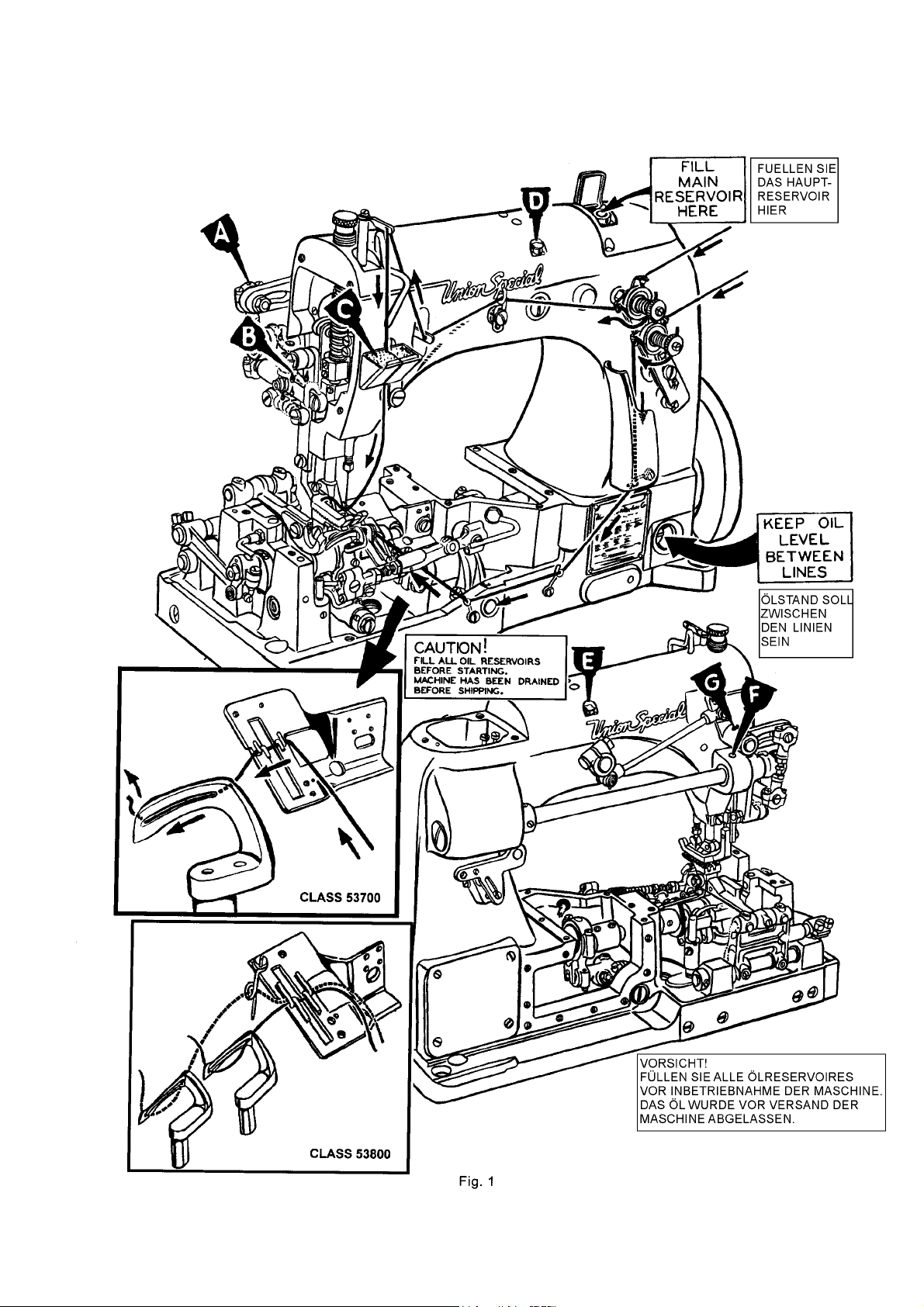
Oil is filled at the spring cap in the top cover and the level
is checked at the sight gauge on the front of the
machine. The oil level should be maintained between
the red lines on the gauge. The capacity of the oil
reservoir is twelve ounces.
The lubrication, which is almost entirely automatic,
requires a minimum of manual oiling. The oiling diagram
on the opposite page is self-explanatory.
The main reservoir supplies oil to the looper drive
eccentric, upper running feed drive eccentric, and
needle lever crank, and the supply is registered at the
front gauge. The entire lower mechanism is served thru
a system of channels and wicks in the main frame by this
reservoir.
A daily check, before the morning start, should be made
and oil added if required. Oil which has gone through
the machine is filtered and pumped back into the main
reservoir making too frequent oilings unnecessary.
Excessive oil in the main reservoir may be drained at the
plug screw in the main frame, directly under the
handwheel.
The accompanying diagram also shows the threading
of the single needle Class 53700B machine. Threading
of the two needle Class 53800B machine is substantially
the same.
Das Öl wird nach Öffnen des gefederten Deckels an
der oberen Abdeckung eingefüllt und am durchsichtigen Ölstandsanzeiger an der vorderen Seite der Maschine kontrolliert. Der Ölstand sollte zwischen den roten
Linien der Ölstandanzeige sein.
Die Schmierung, die beinahe automatisch erfolgt, benötigt nur ein Minimum manuellen Ölens. Das
Öldiagramm auf der Seite gegenüber, ist selbsterklärend.
Das Hauptreservoir versorgt den Greiferwegexzenter,
den oberen Transportwegexzenter, das Nadelhebelgelenk mit Öl und die Versorgung ist am vorderen
Ölschauglas angezeigt. Der gesamte untere Mechanismus wird durch ein Kanalsystem und Dochten im Hauptrahmen durch sein Reservoir versorgt.
Eine tägliche Kontrolle vor Einsatz der Maschine am Morgen sollte durchgeführt und Öl, falls nötig, nachgefüllt
werden. Das Öl, das durch die Maschine gelaufen ist
wird gefiltert und zum Hauptreservoir zurückgepumpt
was zu häufiges Ölen unnötig macht. Überschüssiges Öl
kann an der Verschlussschraube im Hauptrahmen, direkt unter dem Handrad, abgelassen werden.
Das begleitende Diagramm zeigt das Einfädeln der Einnadel Maschine Klasse 53700B. Einfädeln der Zweinadel
Maschine Klasse 53800B ist im wesentlichen gleich.
8
Page 9
9
Page 10
SYNCHRONIZING LOOPER AND NEEDLE MOTIONSSYNCHRONIZING LOOPER AND NEEDLE MOTIONS
SYNCHRONIZING LOOPER AND NEEDLE MOTIONS
SYNCHRONIZING LOOPER AND NEEDLE MOTIONSSYNCHRONIZING LOOPER AND NEEDLE MOTIONS
EINSTELLUNG DER SYNCHRONISAEINSTELLUNG DER SYNCHRONISA
EINSTELLUNG DER SYNCHRONISA
EINSTELLUNG DER SYNCHRONISAEINSTELLUNG DER SYNCHRONISA
NADELBEWEGUNGNADELBEWEGUNG
NADELBEWEGUNG
NADELBEWEGUNGNADELBEWEGUNG
TION VON GREIFER- UNDTION VON GREIFER- UND
TION VON GREIFER- UND
TION VON GREIFER- UNDTION VON GREIFER- UND
Check the synchronization of the looper and needle motions,
using gauge No. T34 and plate No. 21227AD as follows:
Insert the pin, which is included with the gauge, in the looper
rocker ,for 2 needle machine use right looper. Place the gauge
plate on the throat plate seat using the throat plate screws
for attaching. Place the indicator portion of the gauge in
the needle thread take-up wire hole with the pointer to the
right, but do not tighten the set screw at this time. Turn the
handwheel in the operating direction until the pin in the
looper rocker contacts the edge of the gauge plate and set
the indicator so that the left end of the pointer rests against
the top of the needle bar plate and set the indicator so that
the left end of the pointer rests against the top of the needle
bar and the right end of the pointer rests at "0". Tighten the
set screw and note indicator reading. Turn the handwheel in
the reverse direction until the pin again contacts the plate.
If the motions are in synchronization, the pointer of the
indicator will return to the same reading. A variation of one
graduation on the scale is allowable. If the reading is higher
on the scale when the handwheel is turned in the operating
direction, the looper drive lever rocker will have to be moved
to the rear. If the reading is lower, the rocker will have to be
moved to the front.
NOTE: If gauge No. 21227AD is not available, synchronization
may be checked as follows:
Insert the looper in the looper rocker and turn the handwheel
in the operating direction until the point of the looper, moving
to the left, is even with the left side of the needle. Note the
height of the eye of the needle with respect to the looper
point, then turn handwheel in the reverse direction until the
looper point again moves to the left and is even with the left
side of the needle. If the motions synchronize, the height of
the eye of the needle with respect to the looper point will be
the same. A variation of .005 inch is allowable. If the distance
from the eye of the needle to the point of the looper is greater
when the handwheel is turned in the operating direction,
move the looper drive lever rocker to the rear.
Moving it in the opposite direction acts the reverse. Moving
the looper driver lever rocker is accomplished as follows:
Kontrollieren Sie die Synchronisation von Greifer- und Nadelbewegung mit Hilfe der Lehre T34 und der Platte 21227AD wie
folgt:
Setzen Sie den Stift, der der Lehre beigefügt ist, in den Greiferhebel ein, bei Zweinadelmaschinen nehmen Sie den rechten
Greifer. Befestigen Sie die Testplatte der Lehre mit den Stichplattenschrauben auf dem Stichplattenträger. Setzen Sie den
Schaft der Anzeigeskala in die Bohrung für den Fadenabzugshaken im Gestell. Drehen Sie das Handrad in Nährichtung, bis
der Stift im Greiferhebel die Kante der Testplatte berührt und
stellen Sie die Anzeigenskala so, daß das linke Ende des Zeigers
auf dem oberen Ende der Nadelstange liegt und das rechte
Ende des Zeigers auf "0" steht. Ziehen Sie die Befestigungsschraube
an und merken Sie sich die Einstellung. Drehen Sie das Handrad
zurück, bis der Stift wieder an der Testplatte anliegt. Wenn die
Bewegungen übereinstimmen, kehrt der Zeiger der Anzeigeskala
zu der gleichen Einstellung zurück. Ein Unterschied von einem
Teilstrich auf der Skala ist zulässig. Wenn der Zeiger der Anzeigenskala weiter nach oben ausschlägt wenn das Handrad in
Nährichtung gedreht wird, muß die Achse für den Greiferantriebshebel weiter nach hinten geschoben werden. Wenn der
Zeiger nach unten ausschlägt, muß die Achse weiter nach vorne geschoben werden.
BEACHTEN SIE: Falls Lehre No. 21227AD nicht verfügbar ist, kann
die Synchronisation wie folgt vorgenommen werden.
Setzen Sie den Greifer in den Greiferhebel ein und drehen Sie
das Handrad in Nährichtung, bis der Greifer nach links geht und
die Greiferspitze mit der rechten Nadel abschließt. Merken Sie
sich die Höhe des Nadelöhrs in Bezug auf die Greiferspitze, dann
drehen Sie das Handrad in die entgegengesetzte Richtung, bis
der Greifer wieder nach links geht und die Greiferspitze wieder
mit der rechten Nadel abschließt. Wenn die Bewegungen übereinstimmen, ist die Höhe des Nadelöhrs in Bezug auf die Greiferspitze gleich.
Eine Abweichung von .005" = 0,012 mm ist zulässig. Wenn der
Abstand von Nadelöhe zur Greiferspitze größer ist wenn das
Handrad in Nährichtung gedreht wird, bewegen Sie die Greiferantriebshebelachse nach hinten, ein Bewegen nach vorne
bewirkt das Gegenteil.
Remove the close plate, throat plate support, oil reservoir
top cover and loosen the screws in the looper drive eccentric
mechanism and move the eccentric as far to the right as it
will go. Drive the rear bushing to the front or the middle bushing to the rear, as required.
CAUTION: To avoid distorting the parts, remove the plug screw
in the bed behind the rear bushing before driving to the front
and place a horse shoe shaped metal washer
approximately 1/16 inch thick between the looper driver
lever and adjacent bushing when driving the bushing to the
rear. Correctly reposition the looper drive eccentric
mechanism (per spot screws) and tighten all screws securely.
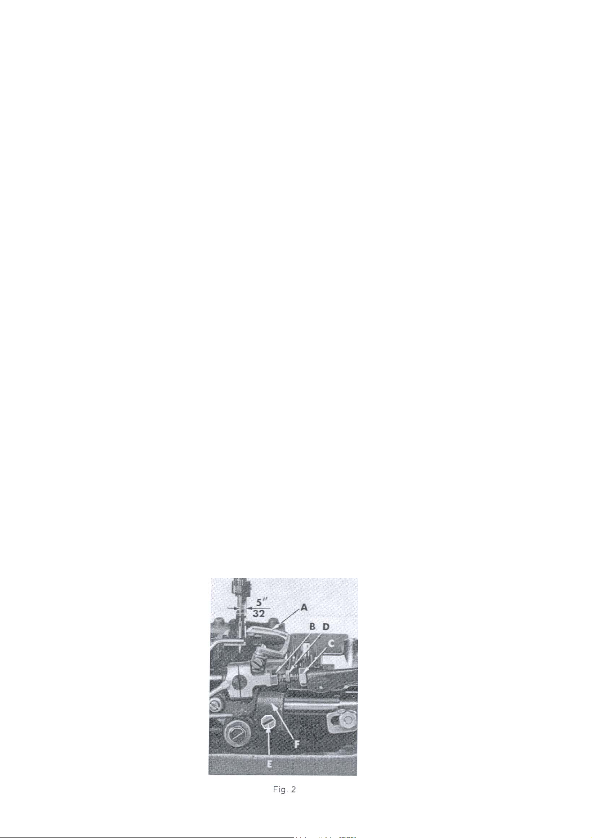
SETTING THE LOOPERSETTING THE LOOPER
SETTING THE LOOPER
SETTING THE LOOPERSETTING THE LOOPER
Insert a new needle, type and size as
specified, with spot or scarf to the rear.
With the looper (A, Fig 2) at its farthest
position to the right, its point should
be 5/32 inch from the centerline of
the needle. If adjustment is required,
loosen nut (B) (it has a left hand
thread) and nut (C) on connecting
rod (D) and turn the connecting rod
forward or backward to obtain 5/32
inch dimension (Fig. 2). Looper gauge
No. 21225-5/32 can be used
advantageously in making this
adjustment. Retighten both nuts, first
nut (C), then nut (B). Make sure the
left ball joint is in vertical position and
does not bind after adjustment.
NOTE: For 2 needle 53800, looper
gauge should be set using the right
needle and looper.
Entfernen Sie die Stichplatte, den Stichplattenträger, die
Ölreservoirabdeckung and lösen Sie die Schrauben des Greiferantriebexzenters und verschieben Sie den Exzenter so weit es
geht nach rechts. Bewegen Sie die hintere Buchse nach vorne
oder die mittlere Buchse nach hinten, wie erforderlich.
VORSICHT: Um ein Verdrehen der Teile zu vermeiden, entfernen
Sie die Verschlussschraube im Gehäuse hinter der hinteren Buchse setzen Sie eine ungefährt 0,16 cm dicke hufeisenförmige Metallscheibe zwischen dem Greiferantriebshebel und der anstoßenden Buchse ein wenn die Bushe nach hinten bewegt wird. Stellen Sie den Greiferantriebsexzenter mit Spitzschrauben wieder
korrekt ein und ziehen Sie die Schrauben wieder fest an.
GREIFEREINSTELLUNGGREIFEREINSTELLUNG
GREIFEREINSTELLUNG
GREIFEREINSTELLUNGGREIFEREINSTELLUNG
Setzen Sie eine neue, Type und Größe wie
angegeben, mit der Hohlkehle nach hinten.
Mit dem Greifer (A, Fig2) in seiner weitesten
rechten Positon, stellen Sie den Abstand zwischen der rechten Greiferendstellung und
Nadelmitte auf 3,9 mm ein. Falls eine Einstellung notwendig ist, lösen Sie die Mutter (B)
(Linksgewinde) und die Mutter (C) an der
Verbindungsstange (D) und drehen Sie die
Verbindungsstange nach vorne oder hinten
um einen Abstand von 3,9 mm zu
erhalten.Benützen Sie die Greifereinstelllehre
21225-5/32. Ziehen Sie beide Muttern, zuerst
Mutter (c), dann Mutter (B) wieder fest an.
Stellen Sie sicher, daß das linke Kugelgelenk
in senkrechter Position ist und sich nach der
Einstellung nicht verhakt.
ANMERKUNG: Bei Zweinadelmaschinen
53800 sollte die Greifereinstellung an der
rechten Nadel und dem rechten Greifer
vorgenommen werden.
10
.
Page 11
SETTING THE LOOPER (CONTINUED)SETTING THE LOOPER (CONTINUED)
SETTING THE LOOPER (CONTINUED)
SETTING THE LOOPER (CONTINUED)SETTING THE LOOPER (CONTINUED)
The looper is set correctly front to back, as it moves to the left
behind the needle, when its point passes as close as possible
without contacting the needle (.001-.002). If adjustment is
necessary, loosen screw (E, Fig. 2) in looper rock shaft (F),
reposition looper as required and retighten screw (E).
EINSTELLEN DES GREIFERS (FORTSETZUNG)EINSTELLEN DES GREIFERS (FORTSETZUNG)
EINSTELLEN DES GREIFERS (FORTSETZUNG)
EINSTELLEN DES GREIFERS (FORTSETZUNG)EINSTELLEN DES GREIFERS (FORTSETZUNG)
Der Greifer ist korrekt eingestellt, wenn er sich sich so nah als
möglich inks hinter der Nadel bewegt ohne diese zu berühren (0.001-.002"). Falls eine Einstellung notwendig ist, lösen Sie
die Schraube (E, Fig2) im Greiferwellenarm (F), stellen Sie den
Greifer wie erforderlich ein und ziehen Sie die Schraube (E)
wieder fest.
SETTING HEIGHT OF NEEDLE BARSETTING HEIGHT OF NEEDLE BAR
SETTING HEIGHT OF NEEDLE BAR
SETTING HEIGHT OF NEEDLE BARSETTING HEIGHT OF NEEDLE BAR
The height of the needle is correct when the top of its eye is 1/
64 inch below the underside of the looper, when the looper
point is flush with the left side of the needle. If adjustment is
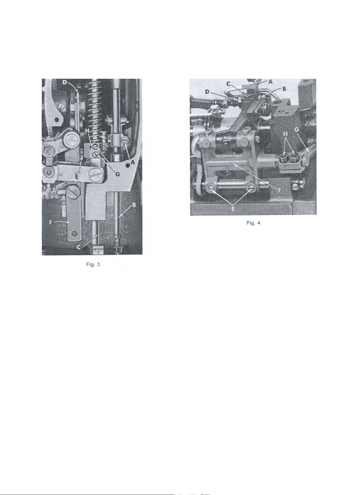
necessary, loosen screw (A, Fig. 3) and move needle bar (B)
up or down as required and retighten screw (A).
SETTING THE FFED DOGSETTING THE FFED DOG
SETTING THE FFED DOG
SETTING THE FFED DOGSETTING THE FFED DOG
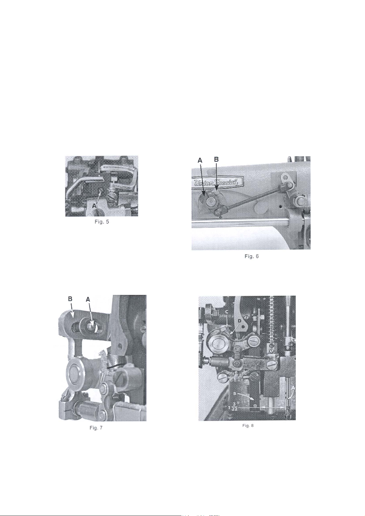
Set the feed dog (A, Fig. 4) in the throat plate so there is
equal clearance on all sides. See that the tips of the teeth
extend 1/2 to 1 full tooth above the throat plate and are
parallel with the throat plate at high point of travel. Height
can be set by loosening feed dog attaching screw (B) and
adjusting feed dog supporting screw (C). Parallelism can be
set by loosening nut (D) and rotating feed dog holder
adjusting screw (A, Fig. 5), as required and retighten nut. Side
clearance can be set by loosening screws (E, Fig. 4) and
moving feed rocker (F) to the right or left, as required.
NOTE: Whenever the feed rocker has been moved, always
check to assure that the feed rocker arm (G) does not bind.
End clearance can be set by loosening screws (H) in the
feed rocker arm (G) and moving feed rocker (F) forward or
backward as required.
HÖHENEINSTELLUNG DER NADELSTHÖHENEINSTELLUNG DER NADELST
HÖHENEINSTELLUNG DER NADELST
HÖHENEINSTELLUNG DER NADELSTHÖHENEINSTELLUNG DER NADELST
Stellen Sie die Nadelstange so hoch ein, daß die Nadelöhroberkante 0.4 mm unter der Greiferspitze ist, wenn sich die
Greiferspitze bei ihrer Bewegung nach links mit der linken
Nadelseite deckt. Falls eine Einstellung notwendig ist, lösen
Sie Schraube (A, Fig.3) und bewegen Sie die Nadelstange
(B) nach Bedarf nach oben oder unten und ziehen Sie die
Schraube (A) wieder fest.
TRANSPORTEUREINSTELLUNGTRANSPORTEUREINSTELLUNG
TRANSPORTEUREINSTELLUNG
TRANSPORTEUREINSTELLUNGTRANSPORTEUREINSTELLUNG
Stellen Sie den Transporteur (A, Fig. 4) in der Stichplatte so ein,
daß an allen Seiten ein gleicher Abstand ist. Die Spitzen der
Zähne sollen in ihrer höchsten Stellung 1,2 mm über die Stichplatte hinausstehen und parallel mit der Stichplatte in der
Aufwärtsbewegung sein. Die Höhe kann durch Lockern der
Transporteurbefestigungsschraube (B) und Einstellung der
Transporteurhalteschraube (C) eingestellt werden. Parallität
kann durch Lockern der Mutter (D) und Drehen der
Transporteureinstellschraube (A, Fig.5), wie erforderlich, eingestellt werden, ziehen Sie die Mutter wieder an. Der Seitendurchgang kann durch Lockern der Schraube (E, Fig.4) und
Bewegen des Transporteurhebels (F) nach rechts or links, je
nach Bedarf, eingestellt werden.
ANMERKUNG: Wenn der Transporteurhebel verstellt wurde
kontrollieren Sie, daß der Transportantriebsarm (G) nicht
klemmt.
Der entgültige Durchgang kann durch Lösen der Schrauben
(H) im Transportantriebsarm (G) und durch Bewegen des
Transporteurhebels (F) nach vorne oder hinten, je nach Bedarf, eingestellt werden.
ANGEANGE
ANGE
ANGEANGE
11
Page 12
INITIAL SETTING OF UPPER RUNNING FEED MECHANISM
ANFANGSEINSTELLUNG DES OBEREN TRANSPORTS
The top feed eccentric assembly should be located on the
main shaft so that the first screw in the eccentric will be in a
perpendicular position to the mainshaft when the needle
bar has risen 1/4 inch from the bottom of its stroke, with the
handwheel turned in the operating direction.
NOTE: Eccentric may need to be advanced or retarded to
obtain proper feeding between top and bottom feeds.
NOTE: The next two paragraphs refer to the maximum height
setting of the top feed mechanism which can be lowered
later to suit sewing conditions.
Turn handwheel in the operating direction until the needle
bar is at the bottom of its stroke. Loosen nut (B, Fig. 6 ) and
move upper feed lift driving lever (A) so that the teeth of the
upper feed dog is 5/32" (7.9mm) for style 53700B and 3/16"
(4.8 to 5.2mm) for style 53800B, above the top of the throat
plate. Then tighten nut (B) securely.
Der obere Transportexzenter sollte so an der Hauptwelle sein,
dass die erste Schraube des Exzenters in einer rechtwinkeligen
Position zur Hauptwelle ist, wenn die Nadelstange sich ca. 63
mm vom unteren Hub durch Drehen des Handrads in
Nährichtung angehoben hat.
BEACHTEN SIE: Der Exzenter muß eventuell nach vorne oder
hinten bewegt werden, um richtigen Einschub zwischen oberer und unterem Transport zu erreichen.
BEACHTEN SIE: Die beiden nächsten Paragrafen weisen auf
die maximale Höheneinstellung des oberen Transports hin, der
später abgesenkt werden kann, um den Nähvoraussetzungen zu entsprechen.
Drehen Sie das Handrad in Nährichtung bis die Nadelstange
an ihrer untersten Anschlag ist. Lösen Sie die Mutter (B, Fi.g 6)
und bewegen Sie den oberen Transporthebel (A) so, daß die
Zähne des oberen Transporteurs 7,9 mm für Klasse 53700B and
4.8 bis 5.2 mm für Klasse 52800B über der Stichplatte sind. Dann
ziehen Sie die Mutter (B) wieder fest an.
The bell crank lever ball joint (A, Fig. 7) should be in the
center of the upper feed bell crank lever (B). The ball joint
may need to be moved slightly to meet sewing conditions.
As the needle bar just begins to rise from the bottom of its
stroke, the distance between the rear of the needle bar
(A, Fig. 8) and the front of the upper feed bar (B) should
be 1 3/32 inch (Fig. 8). Adjustment can be made by
loosening screw (C) in the upper feed driving lever (D) and
moving it forward or rearward as required and retighten
screw (C).
Die Achse des Kugelgelenkes (A, Fig. 7) sollte in der Mitte des
Kulissenhebels (B) sein. Das Kugelgelenk muß eventuell etwas
verschoben werden, um den Nähanforderungen gerecht zu
werden.
Wenn die Nadelstange beginnt sich von dem untersten Hub
abzuheben, sollte der Abstand zwischen der hinteren Nadelstange (A, Fig. 8) und oberen Transportstange (B) 2,76 cm betragen (Fig. 8). Einstellung kann durch Lösen der Schraube (C)
im oberen Transportantriebshebel (D) und Vor- oder Rückwärtsbewegen nach Bedarf gemacht werden und anschließendem Festziehen der Schraube (C).
12
Page 13

INITIAL SETTING OF UPPER RUNNING FEED MECHANISMINITIAL SETTING OF UPPER RUNNING FEED MECHANISM
INITIAL SETTING OF UPPER RUNNING FEED MECHANISM
INITIAL SETTING OF UPPER RUNNING FEED MECHANISMINITIAL SETTING OF UPPER RUNNING FEED MECHANISM
(CONTINUED)(CONTINUED)
(CONTINUED)
(CONTINUED)(CONTINUED)
ANFANF
ANGSEINSTELLUNG DES OBEREN TRANSPORANGSEINSTELLUNG DES OBEREN TRANSPOR
ANF
ANGSEINSTELLUNG DES OBEREN TRANSPOR
ANFANF
ANGSEINSTELLUNG DES OBEREN TRANSPORANGSEINSTELLUNG DES OBEREN TRANSPOR
(FORTSETZUNG)(FORTSETZUNG)
(FORTSETZUNG)
(FORTSETZUNG)(FORTSETZUNG)
TSTS
TS
TSTS
Synchronizing the upper feed with the lower feed can be
accomplished by loosening nut (A, Fig. 9) and moving the
ball stud in the upper feed driving shaft segment lever (B).
Retighten nut.
CHANGING STITCH LENGTHCHANGING STITCH LENGTH
CHANGING STITCH LENGTH
CHANGING STITCH LENGTHCHANGING STITCH LENGTH
Set the stitch to the required length. This is
accomplished by loosening locknut (A,
Fig. 10) (it has a left hand thread) and
turning the stitch adjusting screw (B).
Turning screw (B) clockwise shortens the
stitch and turning it in a counterclockwise
direction lengthens the stitch.
NOTE: Any change in stitch length will
necessitate a corresponding change in
the rear needle guard setting and also
synchronization of the upper running feed
mechanism as described previously.
SETTING THE REAR NEEDLE GUARDSETTING THE REAR NEEDLE GUARD
SETTING THE REAR NEEDLE GUARD
SETTING THE REAR NEEDLE GUARDSETTING THE REAR NEEDLE GUARD
Set the rear needle guard (A, Fig. 11)
horizontally so that it barely contacts
the rear of the needle (B) when at its
most foreward point of travel. It
should be set as low as possible, yet
have its guarding surface in contact
with the needle, until the point of
the looper (C), moving to the left, is
even with the needle. To move
needle guard forward or backward,
merely loosen screw (D), move
needle guard as required and
retighten screw (D). To raise or lower
the needle guard, loosen screw (D)
and turn screw (E) clockwise to lower
or counterclockwise to raise.
Retighten screw (D) after guard is
properly set.
Synchronisierung des oberen und unteren Transports kann
durch Lösen der Mutter (A, Fig. 9) und Bewegen des Kugelbolzens im oberen Transportachsenhebel (B). Ziehen Sie die
Schraube wieder an.
ÄNDERN DER STICHLÄNGEÄNDERN DER STICHLÄNGE
ÄNDERN DER STICHLÄNGE
ÄNDERN DER STICHLÄNGEÄNDERN DER STICHLÄNGE
Stellen Sie den Stich auf die gewünschte
Grösse. Dies kann durch Lösen der Mutter (A,
Fig. 10) (sie hat ein Linksgewinde) und Drehen der Stichregulierungsschraube (B) erreicht werden. Drehen der Schraube (B) im
Uhrzeigersinne kürzt den Stich und Drehen
im Gegenuhrzeigersinn verlängert den Stich.
BEACHTEN SIE: Jede Stichlängenänderung
macht eine entsprechende Änderung in der
hinteren Nadelanschlageinstellung erforderlich und auch die Synchronisation des oberen Transports, wie vorher beschrieben.
EINSTELLEN DES HINTEREN NADELAN-EINSTELLEN DES HINTEREN NADELAN-
EINSTELLEN DES HINTEREN NADELAN-
EINSTELLEN DES HINTEREN NADELAN-EINSTELLEN DES HINTEREN NADELANSCHLAGSSCHLAGS
SCHLAGS
SCHLAGSSCHLAGS
Stellen Sie den hinteren Nadelanschlag
A, Fig. 11) horizontal so, daß dieser
knapp den hinteren Teil der Nadel (B)
berührt, wenn er am vordersten Punkt
seiner Bewegung ist. Er sollte so niedrig
wie möglich sein, jedoch sollte seine
Oberfläche in Kontakt mit der Nadel
sein, bis die Greiferspitze (C), die sich
nach links bewegt, eben mit der Nadel ist. Um den Nadelanschlag nach
vorne oder nach hinten zu bewegen,
lösen Sie Schraube (D), bewegen Sie
den Nadelanschlag nach Bedarf und
ziehen Sie die Schraube (D) wieder an.
Zum Höher- oder Tieferstellen des
Nadelanschlags, lösen Sie Schraube (E)
und drehen Sie die Schraube im Uhrzeigersinn zum Tieferstellen oder im
Gegenuhrzeigersinn zum Höherstellen.
Ziehen Sie die Schraube (D) wieder an
nachdem der Nadelanschlag richtig
eingestellt ist.
SETTING FRONT NEEDLE GUARDSETTING FRONT NEEDLE GUARD
SETTING FRONT NEEDLE GUARD
SETTING FRONT NEEDLE GUARDSETTING FRONT NEEDLE GUARD
Set the front needle guard (F, Fig. 11) so that it barely
contacts the needle (B) until the point of the looper (C),
moving to the left, is just past the left side of the needle.
The looper may brush, but not pick at the needle. The
front needle guard should be set as low as possible to
meet this condition yet not contact the rear needle guard
or looper at any time. To move needle guard forward or
rearward, loosen screws (G), rotate needle guard holder
(D) as required and retighten screws (G). To raise, lower or
rotate needle guard, loosen screws (J), reposition as
necessary and retighten screws after guard is properly set.
THREAD TENSION RELEASETHREAD TENSION RELEASE
THREAD TENSION RELEASE
THREAD TENSION RELEASETHREAD TENSION RELEASE
The thread tension release is set correctly when it begins to
function as the presser foot is raised to within 1/8" of the
end of its travel and is entirely released when the presser
foot has reached its highest position.
EINSTELLUNG DES VORDEREN NADELANSCHLAGSEINSTELLUNG DES VORDEREN NADELANSCHLAGS
EINSTELLUNG DES VORDEREN NADELANSCHLAGS
EINSTELLUNG DES VORDEREN NADELANSCHLAGSEINSTELLUNG DES VORDEREN NADELANSCHLAGS
Stellen Sie den vorderen Nadelanschlag (F, Fig. 11) so ein,
daß er knapp die Nadel (B) berührt bis die Greiferspitze (C)
bei ihrer Linksbewegung gerade links an der Nadel vorbei
ist. Der Greifer kann die Nadel leicht berühren jedoch nicht
anstoßen. Der vordere Nadelanschlag sollte so nieder wie
möglich eingestellt sein, um die Voraussetzugnen zu erfüllten jedoch zu keiner Zeit den hinteren Nadelanschlag oder
Greifer berühren. Um die Nadelanschlag nach vorne oder
hinten zu verschieben, lösen Sie die Schrauben (G), drehen
Sie den Halter für Nadelanschlag (D) wie erforderlich und
ziehen Sie die Schrauben (G) wieder an. Um den Nadelanschlag zu erhöhen, zu senken oder zu drehen lösen Sie die
Schrauben (J), stellen Sie ihn nach Bedarf ein und ziehen
Sie die Schrauben nach korrekter Einstellung wieder an.
FF
ADENSPADENSP
F
ADENSP
FF
ADENSPADENSP
Die Fadenspannungsauslösung muß so eingestellt werden,
daß sie anfängt wirksam zu werden, wenn der Drückerfuß
um 1/8" = 3,2 mm seines Hubes angehoben ist und die
Fäden erst dann vollständig spannungsfrei sind, wenn der
Drückerfuß seine höchstmöglichste Stellung erreicht hat.
13
ANNUNGSAUSLÖSUNGANNUNGSAUSLÖSUNG
ANNUNGSAUSLÖSUNG
ANNUNGSAUSLÖSUNGANNUNGSAUSLÖSUNG
Page 14

SETTING THREAD TENSION RELEASE (CONTINUED)SETTING THREAD TENSION RELEASE (CONTINUED)
SETTING THREAD TENSION RELEASE (CONTINUED)
SETTING THREAD TENSION RELEASE (CONTINUED)SETTING THREAD TENSION RELEASE (CONTINUED)
FF
ADENSPADENSP
F
ADENSP
FF
ADENSPADENSP
ANNUNGSAUSLÖSUNG (FORANNUNGSAUSLÖSUNG (FOR
ANNUNGSAUSLÖSUNG (FOR
ANNUNGSAUSLÖSUNG (FORANNUNGSAUSLÖSUNG (FOR
TSETZUNG)TSETZUNG)
TSETZUNG)
TSETZUNG)TSETZUNG)
If adjustment is needed, loosen tension release lever screw
(A, Fig. 12) located at the back of the machine and move
tension disc separator as required. Retighten screw. After
adjustment there should be no binding at any point.
SETTING HEIGHT OF PRESSER BARSETTING HEIGHT OF PRESSER BAR
SETTING HEIGHT OF PRESSER BAR
SETTING HEIGHT OF PRESSER BARSETTING HEIGHT OF PRESSER BAR
The height of the presser bar (C, Fig. 3) is set
correctly if it is possible to remove the presser
foot when the foot lifter lever (B, Fig. 12) is fully
depressed.
If adjustment is necessary, turn handwheel in
operating direction until the needle bar is in
the low position. Loosen screws (G, Fig. 3), then,
while holding presser foot down on the throat
plate surface, pry up presser bar connection
and guide (H) with a screwdriver to obtain
the 1/16 inch setting and retighten screws.
THREADINGTHREADING
THREADING
THREADINGTHREADING
Draw the looper and needle threads into the
machine and start operating on a piece of
fabric. Refer to threading diagram (Fig. 1) for
manner of threading these machines.
SETTING NEEDLE THREAD TSETTING NEEDLE THREAD T
SETTING NEEDLE THREAD T
SETTING NEEDLE THREAD TSETTING NEEDLE THREAD T
UP WIRE AND FRAME EYELETUP WIRE AND FRAME EYELET
UP WIRE AND FRAME EYELET
UP WIRE AND FRAME EYELETUP WIRE AND FRAME EYELET
Set the needle thread take-up
wire (A, Fig. 13) so that its upper
surface is even with the top of
the hole in the needle bar
thread eyelet (B) when the
needle bar is at the bottom of
its stroke. Lower this setting for
a smaller needle thread loop
or raise it for a larger loop.
Set the needle thread frame
eyelet (C, Fig. 13) perpendicular to the machine base
and 1/4" above the mounting
screw. Lower if more needle
thread is desired in the stitch
or raise for less.
AKE-AKE-
AKE-
AKE-AKE-
Falls eine Einstellung notwenig ist, lösen Sie die Fadenspannungshebelschraube (A, Fig. 12) die sich hinten an der
Maschine befindet und schieben Sie die Auslöseleiste wie
nötig. Ziehen Sie die Schraube wieder an. Nach der Einstellung sollte an keiner Stelle eine Verbindung sein.
EINSTELLUNG DER DRÜCKERFUSSSTEINSTELLUNG DER DRÜCKERFUSSST
EINSTELLUNG DER DRÜCKERFUSSST
EINSTELLUNG DER DRÜCKERFUSSSTEINSTELLUNG DER DRÜCKERFUSSST
Die Höhe der Drückerfussstange (C, Fig. 3) ist rich-
tig eingestellt, wenn es möglich ist, den Drückerfuß zu entfernen wenn der Drückerfusslifterhebel
(B, Fig. 12) ganz heruntergedrückt ist.
Falls eine Einstellung notwendig ist, drehen Sie
das Handrad in Nährichtung bis die Nadelstange
in der niedersten Position ist. Lösen Sie die Schrauben (G, Fig. 3), dann, während Sie den Drückerfuß unten auf der Drückerfußoberfläche halten,
stemmen Sie die Drückerfußstange und Führung
(H) mit einem Schraubenzieher nach oben, um
eine Einstellung von ca. 15 mm zu erhalten und
ziehen Sie die Schrauben wieder an.
EINFEINF
Ziehen Sie den Greifer- und Nadelfaden in die Maschine
und nähen Sie auf einem Stück Stoff. Beachten Sie das Einfädeldiagramm (Fig. 1).
EINF
EINFEINF
ÄDELNÄDELN
ÄDELN
ÄDELNÄDELN
NADELFNADELF
NADELF
NADELFNADELF
NADELFNADELF
NADELF
NADELFNADELF
Stellen Sie den Der Nadelfadenabzugsbügel (A, Fig. 13) so ein, daß
seine obere Fläche eben mit der
Spitze des Loches der Nadelfadenführung (B) ist, wenn die Nadelstange am untersten Hub ihrer Bewegung ist. Höherstellen bringt
eine größere, Tieferstellen eine kleinere Nadelfadenschleife.
Stellen Sie die Nadelfadenführung
(C, Fig.13) rechtwinkeling zu der
Maschine und ca. 6,3 mm über
der Befestigungsschraube. Senken
Sie die Führung falls mehr Nadelfaden im Stich gewünscht wird
oder heben Sie diese für weniger
Nadelfaden.
ADENABZUGSBÜGEL UNDADENABZUGSBÜGEL UND
ADENABZUGSBÜGEL UND
ADENABZUGSBÜGEL UNDADENABZUGSBÜGEL UND
ADENFÜHRUNGADENFÜHRUNG
ADENFÜHRUNG
ADENFÜHRUNGADENFÜHRUNG
ANGENHÖHEANGENHÖHE
ANGENHÖHE
ANGENHÖHEANGENHÖHE
SETTING LOOPER THREAD TSETTING LOOPER THREAD T
SETTING LOOPER THREAD T
SETTING LOOPER THREAD TSETTING LOOPER THREAD T
The looper thread retainer finger (A, Fig. 14)
should be set so that the looper thread is castoff just after the eye of the needle comes up
out of the material. Coordinated positioning
can be acquired by loosening screws (B and
C). After looper thread retainer finger has been
properly set, retighten screws.
PRESSER FOOT PRESSUREPRESSER FOOT PRESSURE
PRESSER FOOT PRESSURE
PRESSER FOOT PRESSUREPRESSER FOOT PRESSURE
Regulate the presser spring regulating screw (D, Fig. 13) so
that it exerts only enough pressure on the presser foot to
feed the work uniformly when a slight tension is placed on
the fabric. Turning it clockwise increases the pressure,
counterclockwise acts the reverse.
AKE-UPAKE-UP
AKE-UP
AKE-UPAKE-UP
14
EINSTELLUNG DES GREIFERFEINSTELLUNG DES GREIFERF
EINSTELLUNG DES GREIFERF
EINSTELLUNG DES GREIFERFEINSTELLUNG DES GREIFERF
Der Greiferfadenaufnehmer (A, Fig. 14) wird so eingestellt, daß der Greiferfaden gerade abgezogen
wird, wenn das Nadelöhr aus dem Material kommt.
Abgestimmte Einstellung kann durch Lösen der
Schrauben (B and C) erreicht werden. Nachdem
der Grefiferfadenrückhaltefinger richtig eingestellt
ist, ziehen Sie die Schrauben wieder an.
DRÜCKERFUSSDRUCKDRÜCKERFUSSDRUCK
DRÜCKERFUSSDRUCK
DRÜCKERFUSSDRUCKDRÜCKERFUSSDRUCK
Stellen Sie die Regulierschraube (D, Fig. 13) für den Druck der
Drückerfußfeder so ein, daß nur so viel Druck auf den Drückerfuß kommt, wie zum gleichmäßigen Transport der Ware erforderlich ist. Die Regulierschraube befindet sich oben auf dem
Kopf direkt hinter der Nadelstange. Drehen im Uhrzeigersinn
verstärkt den Druck, im Gegenuhrzeigersinn bewirkt das Gegenteil.
ADENAUFNEHMERSADENAUFNEHMERS
ADENAUFNEHMERS
ADENAUFNEHMERSADENAUFNEHMERS
Page 15

EXPLODED VIEWS
AND
DESCRIPTION OF PARTS
EXPLOSIONSZEICHNUNGEN
UND
TEILEBESCHREIBUNGEN
15
Page 16

16
Page 17

MAIN FRAME, MISCELLANEOUS COVERS AND PLATES
HAUPTRAHMEN, VERSCHIEDENE ABDECKUNGEN UND PLATTEN
Ref. No.
Pos. No.
1
2
3
4
5
6
7
8
8A
9
10
11
13
14
15
16
17
18
19
20
21
22
23
24
25
26
27
28
29
30
31
32
33
34
35
36
37
38
39
40
41
42
43
44
45
46
47
48
*
*
Part No.
Teil Nr.
22585A
22524
53782B
51382B
22839C
51281P207
51281AC
22760A
35772H
22845B
80
53701
22570
22839
294
53782E
53780
51280J
51280K
51270B
95
53724A
53824A18
21396BN
21396AG
22517B
22889A
53758
20
22848
95
35731A
22513D
22528
53753G
605A
53780A
12934A
22539H
22889D
158B
136
53780B
52A
98A
50-648BLK
51291A
98A
20
22848
Description
Screw
Screw
Oil Reservoir Top Cover
Gasket
Screw
Cloth Plate Cover
Cloth Plate Cover Spring
Screw
Spring Washer
Screw
Screw
Cloth Plate
Screw
Screw
Screw
Head Cover
Throat Plate Support
Dowel Pin, lower
Dowel Pin, upper
Needle Thread Pull-off Wire
Screw
Throat Plate, for Style 53700B
Throat Plate, for Style 53800B
Needle Thread Lubricator
Lubrication Felt
Screw
Adapter Screw
Frame Thread Eyelet
Washer
Screw
Set Screw, for upper feed bell crank
lever shaft
Presser Bar Connection Guide Plate
Screw
Screw
Thrust Bracket
Screw
Throat plate Support Rod
Nut
Plug Screw
Plug Screw
Frame Thread Eyelet, for Style 53800B
Screw
Throat Plate Support Rod Bracket
Frame Thread Eyelet, for Style 53700B
Screw
Lucite Oil Gauge
Looper Thread Guard
Screw, for looper thread guard
asher, for 22848
W
Screw for 51282AH
Beschreibung Amt. Req.
Anzahl
Zylinderschraube
Linsensenkschraube
Abdeckplatte
Dichtung
Zylinderschraube
Tischplattendeckel
Deckelfeder
Zylinderansatzschraube
Scheibe
Zapfenschraube
Linsensenkschraube
Tischplatte
Zylinderschraube
Zylinderschraube
Zylinderschraube
Kopfdeckel
Stichplattenträger
Stift, unterer
Stift, oberer
Fadenabzugshaken
Gewindestift
Stichplatte für Klasse 53700B
Stichplatte für Klasse 53800B
Fadenöler
Schmierfilz
Zylinderschraube
Zylinderschraube
Fadenführung
Unterlagscheibe
Halbrundschraube
Gewindestift
Führungsplatte
Zylinderschraube
Zylinderschraube
Anlaufblock
Gewindestift
Bolzen
Sechskantmutter
Verschlußschraube
Gewindestift
Fadenführung für Klasse 53800B
Zylinderschraube
Platte
Fadenführung für Klasse 53700B
Zylinderschraube
Ölstandsauge
Schutzblech
Zylinderschraube für Schutzblech
Unterlagscheibe
Halbrundschraube
2
7
1
1
2
1
1
3
3
1
3
1
2
3
3
1
1
2
2
1
1
1
1
1
2
1
1
1
1
1
1
1
2
4
1
1
1
1
1
1
1
3
1
1
3
3
1
1
1
3
3
* Not shown on picture plate
* Nicht auf der Abbildung gezeigt
17
Page 18

18
Page 19

BUSHINGS, OIL TUBES, WICKS AND MISCELLANEOUS COVERS
BUCHSEN, ÖLSCHLÄUCHE, DOCHTE UND VERSCHIEDENE ABDECKUNGEN
Ref. No.
Pos. Nr.
1
2
3
4
5
6
7
8
9
10
11
12
13
14
15
16
17
18
19
20
21
22
23
24
25
26
27
28
29
30
31
32
33
34
35
36
37
38
39
40
41
42
43
44
45
46
47
48
49
50
51
52
53
54
55
56
57
58
59
60
61
62
63
64
65
66
67
68
69
70
71
*
*
*
Part No.
Teil Nr.
22541B
52882AD
39582L
52882AC
50-789BLK
52882AA
90
90
52882P
52882Y
22539D
21375BQ
93
FP52891B
FP52890C
51242C
21657X
FP51242R
FP52944U
52883R
53790A
52894AB
52894AC
FP53750A
FP53750B
80689D
FP51154D
FP53788A
FP52890C
FP51254C
FP51290T
90
22560B
52894AK
FP52944T
660-136
258A
FP52936
FP51242S
52882L
52882AT
52882AE
52882AS
22548
22848
22733B
41394A
22883A
643-127BLK
51493BQ
531
51493AG
51493D
51493BR
22569B
51493AH
51493BH
51493BJ
22823A
G22823B
51493AY
51295A
22571A
666-111
666-179
666-118
666-65
35178D
666-114
22889C
51493BK
22848
51282AH
20
Description
Screw
Crank Chamber Cover, upper
Oil Cap
Oil Cap Torsion Spring
Oil Cap Hinge Pin
Drip Plate
Screw
Screw
Gasket (31282C)
Baffle Plate
Plug Screw
Safety Belt Guard (B21375AH)
Screw
Main Shaft Bushing Housing, incl bush.
Main Shaft Bushing, left and right
Looper Drive Lever Shaft Bushing, front
Tension Release Lever Shaft Bushing
Looper Drive Lever Shaft Bush. middle
Looper Rock Shaft Bushing, right
Presser Foot Lifter Lever Bushing
Upper Running Feed Dri veRock Shaft Bush., right
Oil Tube Holder
Oil Tube, for feed lift and looper avoid ecc.
Needle Lever Bushing, front
Needle Lever Bushing, rear
Oiler
Needle Bar Bushing, lower (51254D)
Presser Bar Bushing, lower
Up Running Fd Dr Rock Shaft Bush,left
Needle Bar Bushing, upper
Main Shaft Bushing, middle
Screw
Screw
Oil Tube, for looper rocker and left ball joint
Looper Rock Shaft Bushing, left
Feed Crank Link Oil Tube
Nut
Feed Rocker Shaft Bushing
Looper Drive Lever Shaft Bushing, rear
Oil Reservoir Back Cover
Gasket
Crank Chamber Cover, lower
Gasket
Screw
Screw
Screw
Gasket
Plug Screw
Gasket
Oil Pump Driven Gear
Screw
Oil Pump Housing
Oil Pump Driving Shaft
Oil Pump Driving Shaft Gear (51493E)
Screw
Oil Pump Housing Cover
Filter Cap Assembly
Washer, rubber
Screw
Screw (22823B)
Oil Pan Base Plate
Mounting Isolator
Plug Screw
Oil Wick
Wedge Pin
Oil Wick
Oil Wick
Spring
Oil Wick
Plug Screw
Lint Filter Screen
Screw, for 51282AH
Oil Shield, end and back
Washer
Beschreibung
Zylinderschraube
Deckel, komplett
Ölklappdeckel
Feder
Scharnierstift
Ölfangblech
Zylinderschraube
Zylinderschraube
Dichtung Gummikork
Schutzblech
Schraube
Riemenschutz nur für halbversenkt
Zylinderschraube
Kurbelwellenlagergehäuse
Buchse
Buchse
Buchse
Buchse
Buchse
Buchse
Buchse für Schwingachse
Ölrohrhalter
Ölrohr
Buchse für Nadelhebel
Buchse für Nadelhebel
Einschlag-Kugelöler
Drückerfußstange Buchse, unten
Drückerfußstange Buchse, unten
Buchse
Buchse
Buchse
Zylinderschraube
Gewindestift
Ölrohr
Buchse
Knieölrohr
Sechskantmutter
Buchse
Buchse
Abdeckplatte hinten
Dichtung
Abdeckblech
Dichtung
Zylinderschraube
Halbrundschraube
Verschlußschraube
Dichtung
Verschlußschraube
Dichtung
Kegelrad
Gewindestift
Ölpumpengehäuse
Pumpenachse
Zahnrad
Zylinderschraube
Gehäusedeckel
Ölfilterdeckel, kpl.
Dichtungsgummi
6Kt Senkschraube
Senkschraube
Ölwanne
Puffer
Gewindestift
Öldocht
Aufnahmestift
Öldocht mit Feder
Ölfilz
Feder
Öldocht
Schraube
Filter
Halbrundschraube
Ölschutzblech
Unterlagscheibe
Amt. Req.
Anzahl
3
1
1
1
1
1
2
2
1
1
1
1
2
1
2
1
1
1
1
1
1
1
1
1
1
1
1
2
1
1
1
1
1
1
1
1
1
2
1
1
1
1
1
4
9
1
2
1
1
1
2
1
1
2
3
1
1
1
2
1
1
4
15
2
2
2
2
4
2
2
1
2
1
2
19
Page 20

20
Page 21

CRANKSHAFT AND UPPER FEED DRIVING ROCK SHAFT PARTS
KURBELWELLE UND OBERTRANSPORT TEILE
Ref. No.
Pos. No.
1
2
3
4
5
6
7
8
9
10
11
12
13
14
15
16
17
18
19
20
21
22
23
24
25
26
27
28
29
30
31
32
33
34
35
36
37
38
39
40
41
42
43
44
45
46
47
48
49
50
51
52
Part No.
Teil Nr.
51321G
22894H
22894E
22569B
56390E
660-202
FP9660B
98
666-53
29126BJ
22587
22894C
80630D
53716
FP29476DT
22559E
51216
51493BP
22560B
FP51242P
22729
51243C
29105Q
22559B
22894D
22894C
22559A
52841G
51242Y
51242L
52841J
51242M
51242M
22852A
81
12982
269
22747
41255B
52854
22729C
454A
258
53752
22811
80630C
660-202
52849C
95
52849
29066X
97A
Description Beschreibung
"V" Belt Handwheel
Spot Screw, for round / "V" belt handwheel
Set Screw, for round and "V" belt handwheel
Screw, for housing
Crankshaft Bearing Housing Gasket
"O" Ring, for Pulley
Crankshaft Thrust Collar (9660B)
Set Screw
Lubricating Felt
Upper Running Feed Drive Eccentric Assembly
Bearing Cap Screw
Eccentric Set Screw
Nut, right thread (15430D)
Top Feed Driving Connecting Rod
Crankshaft Assembly (29476DT)
Bearing Cap Screw
Needle Lever Connecting Rod Tube
Pump Driving Gear
Screw
Looper Drive Lever Shaft (51242P)
Screw
Ball Stud Guide Fork
Looper Drive Eccentric Assembly
Bearing Cap Screw, upper
Eccentric Spot Screw
Eccentric Set Screw
Bearing Cap Screw, lower
Locking Stud
Looper Drive Lever Rocker
Thrust Washer
Nut
Washer
Washer
Clamp Screw
Spot Screw
Lock Nut
Nut, left thread
Screw
Ball Stud Guide Fork
Ball Joint Assembly
Bearing Cap Screw
Washer
Nut
Upper Feed Driving Shaft Segmet Lever
Clamp Screw
Nut, left thread
Oil Seal Ring
Upper Running Feed Dr Rock Shaft Thrust Collar
Set Screw
Upper Running Feed Drive Rock Shaft
Bearing Assembly
Bearing Cap Screw
Handrad
Gewindestift
Gewindestift
Zylinderschraube
Dichtung
Dichtring
Stellring
Gewindestift
Ölfilz
Exzenter, komplett
Zylinderschraube
Gewindestift
Sechskantmutter
Verbindungsstange
Kurbelwelle komplett
Zylinderschraube
Verbindungsrohr
Kegelrad
Gewindestift
Achse
Zylinderschraube
Führungsgabel
Greiferantriebsexzenter
Zylinderschraube
Gewindestift
Gewindestift
Zylinderschraube
Klemmbolzen
Schwinghebel
Scheibe
Rundmutter
Scheibe
Scheibe
6Kt Schraube
Gewindestift
Sechskantmutter
Sechskantmutter
Schraube
Führungsgabel
Kugellager
Zylinderschraube
Unterlagscheibe
Sechskantmutter
Hebel
6Kt Schraube
Sechskantmutter
Dichtring
Stellring
Gewindestift
Achse
Nadelhebellager
Zylinderschraube
Amt. Req.
Anzahl
1
1
1
3
1
1
1
2
1
1
2
2
2
1
1
2
1
1
2
1
2
2
1
2
2
3
2
1
1
2
1
1
1
1
1
1
1
1
1
1
2
1
1
1
1
1
1
1
2
1
1
2
21
Page 22

22
Page 23

FEED ROCKER SHAFT, MAIN SHAFT AND LOOPER ROCKER FRAME ROCKER SHAFT PARTS
ACHSE, HAUPTWELLE UND GREIFERRAHMEN-TEILE
Ref. No.
Pos. No.
1
2
3
4
5
6
7
8
9
10
11
12
13
14
15
16
17
18
19
20
21
22
23
24
25
26
27
28
29
30
31
32
33
34
35
36
37
38
39
40
41
42
43
44
45
46
47
48
49
50
51
52
53
54
55
56
57
58
Part No.
Teil Nr.
8
51134P
51134R
51134C
51235
98
482
98
29476RF
FP51235A
51235G
22519C
77
51054A
666-149
51236M
51236L
269
20
53722
22768
51236B
82
51236G
29476BJ
22894D
PF51145
PI18
666-82
51236J
77
29476AR
22894D
FP51145
PI18
666-82
51236J
77
FP51423C
96
22580D
55244G
51244N
51216N
18
51244L
52470
FP51244B
22519H
51144
51244
96
98
52444B
52825D
33174B
77
51325
Description
Feed Rocker Shaft (8A)
Lubricating Felt
Lubricating Felt Guard
Feed Bar Shaft
Feed Rocker
Screw
Feed Rocker Shaft Collar
Screw
Feed Rocker Arm and Link Assm.
Feed Rocker Arm (51235X)
Washer
Screw
Set Screw
Feed Crank Link Pin
Lubricating Felt
Feed Crank Link Assembly
Feed Crank Link Ferrule
Nut, left thread
Washer
Mainshaft
Screw
Feed Crank Stud Cap
Stitch Regulating Screw
Feed Crank Stud
Looper A
Looper Avoid Eccentric Assembly
Take-up (51423C)
Locking Stud
Looper Rock Shaft Collar
Washer
Nut
Thrust Washer
Stop, for looper connecting rod
Looper Rock Shaft Arm (51244B)
Looper Rock Shaft
Looper Rocker Frame, for Style 53800B
Spot Screw
Set Screw
Looper Rocker Frame, for Style 53700B
Looper Needle Guard Holder, for 53700B
Looper Needle Guard, for Style 53700B
void Eccentric Assembly
Spot Screw
Feed Lift and Looper Avoid Ecc. Link
Pin
Lubricating Felt
Link Pin
Set Screw
Spot Screw
Feed Lift and Looper Avoid Ecc. Link
Pin
Lubricating Felt
Link Pin
Set Screw
Time Spot Screw
Set Screw
Screw
Screw
Set Screw
Beschreibung Amt. Req.
Anzahl
Achse
Öldocht
Ölfilzhalter
Transporteurträgerachse
Transportrahmen
Gewindestift
Stellring
Gewindestift
Verbindungslager komplett
Transportrahmenarm
Unterlagscheibe
Sechskantschraube
Zylinderschraube
Konischer Stift
Ölfilz
Transportgelenk mit Nadellager
Buchse
Sechskantmutter
Unterlagscheibe
Hauptwelle
Zylinderschraube
Führungsplättchen
Zylinderschraube
Gelenkbolzen
Gelenk komplett
Gewindestift
Gelenk
Stift
Ölfilz
Gelenkstift
Zylinderschraube
Greiferseitwegexzenter komplett
Gewindestift
Gelenk
Stift
Ölfilz
Gelenkstift
Zylinderschraube
Fadenaufnehmer
Gewindestift
Gewindestift
Klemmschraube
Stellring
Scheibe
Sechskantmutter
Anlaufscheibe
Winkel
Greiferantriebshebel
6Kt Schraube
Greiferachse
Greiferrahmen
Gewindestift
Gewindestift
Greiferrahmen
Halter für Nadelanschlag
Zylinderschraube
Zylinderschraube
Nadelanschlag für Klasse 53700B
1
1
1
1
1
2
2
2
1
1
2
2
2
1
1
1
1
1
1
1
2
1
1
1
1
1
1
1
1
1
1
1
1
1
1
1
1
1
1
1
1
1
1
1
1
2
1
1
1
1
1
1
1
1
1
2
2
1
23
Page 24

24
Page 25

FEED BAR, LOOPER ROCKER AND LOOPER CONNECTING ROD PARTS
TRANSPORTEURTRÄGER, GREIFERHEBEL UND GREIFERVERBINDUNGSSTANGEN-TEILE
Ref. No.
Pos. No.
1
2
3
4
5
6
7
8
9
10
11
12
13
14
15
16
17
18
19
20
21
22
23
24
25
26
27
28
29
30
31
32
33
34
35
36
37
38
39
40
41
42
43
44
45
46
47
48
49
50
51
52
53
Part No.
Teil Nr.
FP51134X
22560B
56334L
538
22863
6042A
258
77
22834
53705A
22528
51225
53825
22801
51225W
22585B
53805A
53825
18
52841A
22729C
269
51240D
51241K
56341G
22729C
50-458BLK
12538
53710
73A
51409C
1740
21211
73
73
29192
51213
51745
15465F
22894W
258
22829
51246
51508M18
51909C
29192D
51513
51745
15465F
22894W
258
22829
FP51242W
22811B
22894H
Description
Feed Bar ( 51134X)
Set Screw
Feed Dog Holder (56334E)
Feed Dog Height Adjusting Screw
Feed Dog Holder Adjusting Screw
Washer
Feed Dog Holder Nut
Screw
Needle Guard Adjusting Screw
Lower Feed Dog, for Style 53700B
Screw
Needle Guard, for Style 53700B
Needle Guard, for Style 53800B
Needle Guard Guide Screw
Washer
Screw
Lower Feed Dog, for Style 53800B
Needle Guard, for Style 53800B
Nut
Looper Connecting Rod Ball Joint, left
Bearing Cap Screw
Nut, left thread
Looper Connecting Rod, 1 11/32" long
Looper Connecting Rod Ball Joint, right
Spring
Bearing Cap Screw
Spring Pin
Nut
Looper Needle Guard, for 53700B older
models
Screw
Looper, for Style 53700B
Looper Needle Guard Pin
Looper Collar
Screw, for Style 53700B
Screw, for Style 53800B
Looper Rocker Assy, for Style 53700B
Looper Rocker
Looper Rocker Cone Stud
Looper Rocker Cone
Set Screw
Lock Nut
Lock Nut Screw
Nut
Looper, front, for Style 53800B
Looper, rear, for Style 53800B
Looper Rocker Assy, for Style 53800B
Looper Rocker
Looper Rocker Cone Stud
Looper Rocker Cone
Set Screw
Lock Nut
Lock Nut Screw
Looper Drive Lever (51242W)
Clamp Screw
Spot Screw
, for Style 53700B
Beschreibung Amt. Req.
Anzahl
Transporteurträger
Gewindestift
Transporteurhalter
Linsensenkschraube
Transportgelenkschraube
Scheibe
Sechskantmutter
Zylinderschraube
Bundschraube
Transporteur für Klasse 53700B
Zylinderschraube
Nadelanschlag für Klasse 53700B
Nadelanschlag für Klasse 53800B
Schaftschraube
Unterlegscheibe
Zylinderschraube
Transporteur für Klasse 53800B
Nadelanschlag für Klasse 83800B
Sechskantmutter
Kugellager komplett
Zylinderschraube
Sechskantmutter
Greiferverbindungsstange
Greiferverbindungsgelenk
Blattfeder
Zylinderschraube
Stift
Sechskantmutter
Greiferschutz für ältere Modelle der
Klasse 53700B
Zylinderschraube
Greifer für Klasse 53700B
Stift
Unterlagsring für Klasse 53700B
Zylinderschraube für Klasse 53700B
Zylinderschraube für Klasse 53800B
Greiferhebel komplett für Klasse 53700B
Greiferhebel
Kegelbolzen
Kegelring
Gewindestift
Sechskantmutter
Zylinderschraube
Sechskantmutter
Greifer, vorn, für Klasse 53800B
Greifer, hinten, für Klasse 53800B
Greiferhebel. komplett
Greiferhebel
Kegelbolzen
Kegelring
Gewindestift
Sechskantmutter
Zylinderschraube
Greiferantriebshebel
6Kt Schraube
Gewindestift
1
1
1
1
1
1
1
1
1
1
1
1
1
1
1
1
1
1
2
1
2
1
1
1
1
2
1
1
1
1
1
1
1
1
2
1
1
1
1
2
1
1
1
1
1
1
1
1
1
2
1
1
1
1
1
25
Page 26

26
Page 27

UPPER FEED DRIVE, NEEDLE BAR AND PRESSER BAR PARTS
OBERTRANSPORTEUR, NADELSTANGE UND DRÜCKERFUSSSTANGENTEILE
Ref. No.
Pos. Nr.
1
2
3
4
5
6
7
8
9
10
11
12
13
14
15
16
17
18
19
20
21
22
23
24
25
26
27
28
29
30
31
32
33
34
35
36
37
38
39
40
41
42
43
44
45
46
47
48
49
50
51
52
53
54
55
56
57
58
59
60
61
62
63
64
65
66
67
Part No.
Teil Nr.
53753H
22585S
9937
51770-88
51771
22773A
22773B
22764A
53783D
531
53755
22787D
J87J
FP56354D
22598D
FP9660B
98
53752E
J87J
51054A
666-149
53752D
627A
80557
12934A
53788B
53783C
22560B
41071G
33174B
52889A
53787
22768
56358
652C9
29348AW
52336A
666-149
77
FP52715
56350B
22528
FP56354D
22564
51254K
22562A
22591A
HA81
22768
56358A
51217
56
53720
88
53726
56458
56458A
56517B18
50J16
98
7018E5
7040-6
187B
89
53820-18
88
53826
Description
Upper Running Feed Bar
Screw, for upper feed dog
Nut
Upper Running Feed Bar Spacing Link
Upper Running Feed Bar Link Bushing
Screw
Screw
Screw
Presser Bar Connection Block
Screw
Upper Running Feed Foot Lifter Link (53755A)
Screw
Screw
Connection Link (56354D)
Screw
Upper Run Feed Drive Rock Shaft Collar (9660B)
Screw
Upper Running Feed Lifter Drive Link(56752F)
Screw
Link Pin
Lubricating Felt
Upper Running Feed Driving Lever
Clamp Screw
Washer
Nut
Presser Bar
Presser Bar Connection and Guide
Screw
Nut
Screw
Presser Bar Bushing, upper and presser spring
regulator
Presser Spring
Screw
Needle Bar Thread Eyelet, for Style 53700B
Needle Bar Eyelet Lock Washer
Needle Lever Assembly (29248U)
Needle Bar Connection Link Pin
Lubricating Felt
Screw
Needle Lever (53715A)
Needle Lever Bushing
Screw
Needle Bar Connection Link (56354D)
Screw
Needle Bar Connection
Screw
Screw
Screw
Screw
Needle Lever Thread Eyelet, for Style 53700B
Needle Bar, for Style 53700B
Needle Clamp Nut, for Style 53700B
Presser Foot, for Style 53700B
Screw, for Style 53700B (78)
Upper Feed Dog, for Style 53700B
Needle Lever Thread Eyelet, for Style 53800B
Needle Bar Thread Eyelet, for Style 53800B
Needle Bar, for Style 53800B
Needle Stop Pin
Set Screw, for needles for Style 53800B
Needle Bar Head, for Style 53800B
Thread Guide
Thread Guide Screw
Screw, for Style 53800B
Presser Foot, for Style 53800B
Screw
Upper Feed Dog, for Style 53800B
Beschreibung
Oberer Transporteurträger
Zylinderschraube
Sechskantmutter
Gelenkstück
Buchse
Zylinderschraube
Zylinderschraube
Gewindestift
Verbindungsblock für Drückerfußstange
Gewindestift
Verbindung
Zylinderschraube
Zylinderschraube
Nadelstangengelenk
Zylinderschraube
Stellring
Gewindestift
Gelenkstück
Zylinderschraube
Zylinderstift
Ölfilz
Hebel
6Kt Schraube
Unterlagscheibe
Sechskantmutter
Drückerfußstange
Drückerfußführung
Gewindestift
Sechskantmutter
Zylinderschraube
Gewindebuchse
Feder
Zylinderschraube
Fadenführung an Nadelstange für Klasse 53700B
Zahnscheibe
Nadelhebel komplett
Zylinderstift
Ölfilz
Zylinderschraube
Nadelhebel
Buchse für Nadelhebel
Zylinderschraube
Nadelstangengelenk
Zylinderschraube
Mitnehmer für Nadelstange
Zylinderschraube
Gewindestift
Gewindestift
Zylinderschraube
Fadenführung am Nadelhebel für Klasse 53700B
Nadelstange für Klasse 53700B
Sechskantmutter für Klasse 53700B
Drückerfuß für Klasse 53700B
Gewindestift für Klasse 53700B
Transporteur oben, für Klasse 53700B
Fadenführung am Nadelhebel für Klasse 53800B
Fadenführung auf Nadelstange für Klasse 53800B
Nadelstange für Klasse 53800B
Stift für Klasse 53800B
Gewindestift für Klasse 53800B
Nadelkopf für Klasse 53800B
Fadenspannungsplättchen
Zylinderschraube
Gewindestift für Klasse 53800B
Drückerfuß für Klasse 53800B
Gewindestift
Obertransporteur für Klasse 53800B
Amt. Req.
Anzahl
1
1
3
1
2
1
1
1
1
1
1
1
1
1
1
1
2
1
1
2
1
1
1
1
1
1
1
2
1
1
1
1
1
1
1
1
2
1
1
1
1
2
1
1
1
1
1
1
1
1
1
1
1
2
1
1
1
1
1
2
1
1
1
1
1
2
1
27
Page 28

28
Page 29

UPPER FEED LIFT AND PRESSER FOOT LIFTER PARTS
OBERE WELLE UND DRÜCKERFUßHEBEL-TEILE
Ref. No.
Pos. No.
1
2
3
4
5
6
7
8
9
10
11
12
13
14
15
16
17
18
19
20
21
22
23
24
25
26
27
28
29
30
31
32
33
34
35
36
37
38
39
40
41
42
43
44
45
Part No.
Teil Nr.
53750
53754
55235D
6042A
55235E
77
51236J
53754A
53754F
51242L
FP53754D
482C
22894C
22768
18
15037A
21657E
53754G
22729C
15037A
43242N
43242P
43241D
22729C
41255B
22747
22882
53783R
53783P
20
18
240
9255
53783L
52883S
22557B
56383AB
53783N
22537
53783T
21657Y
402
22596
21657W
660-207
Description
Needle Lever and Upper Feed Lift
Driving Lever Shaft
Upper Running Feed Lift Driving Lever
Locking Stud
Locking Stud Washer
Locking Stud Nut
Screw
Screw
Link Pin
Upper Running Feed Driving Connecting
Washer
Upper Feed Bell Crank Lever (53754D)
Collar
Set Screw
Screw
Ball Joint Locking Nut
Ball Joint Regulating Nut
Washer, for 53754G
Bell Crank Lever Ball Joint, upper
Bearing Cap Screw
Nut, right thread
Connecting Rod, one inch long
Nut, left thread
Bell Crank Lever Ball Joint, lower
Bearing Cap Screw
Fork for 43241D
Screw for 41255B
Screw
Presser Foot Lifter Adjusting Plate
Presser Foot Lifter Lever Link, adjustable
Washer
Nut
Screw
Washer
Presser Foot Lifter Lever Bell Crank
Presser Foot Lifter Lever Bell Crank Spring
Screw
Presser Foot Lifter Lever Connecting Rod
Presser Foot Lifter Lever, internal
Screw
Presser Foot Lifter and Tension Disc Release
Lever
Tension Release and Foot Lifter Lever Shaft
Connection
Screw
Screw
ension Release and Foot Lifter Shaft
T
Oil Seal Ring
Beschreibung Amt. Req.
Anzahl
Nadelhebel und oberer Transport
Hebelachse
Hebel
Klemmschraube
Scheibe
Sechskantmutter
Zylinderschraube
Zylinderschraube
Gelenkstift
Verbindungsstange
Scheibe
Hebel
Stellring
Zylinderschraube
Zylinderschraube
Sechskantmutter
Sechskantmutter
Scheibe
Kugelgelenk
Zylinderschraube
Sechskantmutter
Verbindungsstange
Sechskantmutter
Kugellager komplett
Zylinderschraube
Führungsgabel für 43241D
Schraube für 41255B
Sechskantschraube
Führungsblech
Verbindung
Unterlagscheibe
Sechskantmutter
Zylinderschraube
Unterlagscheibe
Lifterzwischenhebel
Drückerfußfeder
Zylinderschraube
Drückerfußverbindungsstange
Lifterhebelverbindung
Gewindestift
Drückerfußlifterhebel
Verbindungssteil
Zapfenschraube
Zylinderschraube
Achse
Dichtring
1
1
1
1
1
1
1
2
1
1
1
1
2
1
1
1
1
1
2
1
1
1
1
2
1
1
1
1
1
1
1
1
2
1
1
1
1
1
1
1
1
1
1
1
1
1
29
Page 30

30
Page 31

THREAD TENSION PARTS FOR SINGLE NEEDLE MACHINES
FADENSPANNUNGSTEILE FÜR EINNADEL MASCHINEN
Ref. No.
Pos. No.
1
2
3
4
5
6
7
8
9
10
11
12
13
14
15
16
17
18
19
20
21
22
23
Part No.
Teil Nr.
43266
80557
52892
51192G
21657-3
51292A
109
51292G
51292F14
51292C
51292F1
22598
50-216BLK
51257P
51204B
51204
51204A
22798A
51204C
77
J87J
21657E
22528
Description
Tension Post Nut
Spacing Washer
Tension Post Support
Tension Post Thread Eyelet
Tension Disc Separator
Tension Post Ferrule
Tension Disc
Tension Post
Tension Spring, needle thread
Tension Regulating Nut
Tension Spring, looper thread
Screw
LOOPER THREAD TAKE-UP PARTS
GREIFERFADENAUFNEHMERTEILE
Dowel Pin
Cast-off Support Plate
Auxiliary Cast-off
Cast-off Wire
Cast-off Wire Support
Screw
Cast-off Retaining Wire Support Bracket
Screw
Screw
Washer
Screw
Beschreibung Amt. Req.
Anzahl
Sechskantmutter
Unterlagscheibe
Träger
Fadenführung
Auslöseleiste
Fadenspannungshülse
Fadenspannungsscheibe
Fadenspannungsschraube
Feder für Fadenspannung
Rändelmutter
Feder für Fadenspannung
Zylinderschraube
Stift
Fadenabzugsplatte
Hilfsabzug
Fadenaufnehmer
Halter für Fadenaufnehmer
Zylinderschraube
Träger
Zylinderschraube
Zylinderschraube
Scheibe
Zylinderschraube
1
3
1
2
1
2
4
2
1
2
1
1
2
1
1
1
1
1
1
1
2
1
1
24
25
26
27
28
29
20
31
32
33
43266
56382X
51192G
21657-4
51292A
109
51292G
51292F1
51292F14
51292C
THREAD TENSION PARTS FOR TWO NEEDLE MACHINES
FADENSPANNUNGSTEILE FÜR ZWEINADELMASCHINEN
Tension Post Nut
Tension Post Support
Tension Post Thread Eyelet
Tension Disc Separator
Tension Post Ferrule
Tension Disc
Tension Post
Tension Spring, looper thread
Tension Spring, needle thread
Tension Regulating Nut
Sechskantmutter
Fadenspannungsträger
Fadenführung
Auslöseleiste
Fadenspannungshülse
Fadenspannungsscheibe
Fadenspannungsschraube
Feder für Fadenspannung
Feder für Fadenspannung
Rändelmutter
2
1
4
1
4
8
4
2
2
4
31
Page 32

32
Page 33

ACCESSORIES
ZUBEHÖR
Ref. No.
Pos. No.
1
-
2
3
4
5
6
Part No.
Teil Nr.
21101W4
21101W2
118G
21201
421E
421C34
21388
Description
Thread Stand, complete, for Style
53800B
Thread Stand, complete, for Style
53700B
Tweezer (12288403)
Screw Driver
Hook (660-264)
Treadle Chain (421D28)
Wrench
Beschreibung Amt. Req.
Anzahl
Fadenständer komplett für Klasse
53800B
Fadenständer komplett für Klasse
53700B
Pinzette
Schraubendreher
Haken
Lifterkette
Schlüssel
1
1
1
1
1
1
1
33
Page 34

NUMERICAL INDEX OF PARTS
NUMERISCHES TEILEVERZEICHNIS
PART NO. PAGE NO.
TEIL NR. SEITE NR.
109 ... 31
1 18G ... 33
12538 ... 25
12934A ... 17, 27
12982 ... 21
136 ... 17
15037A ... 29
15465F ... 25
158B ... 17
1740 ... 25
18 ... 23, 25, 29
187B ... 27
20 ... 17, 19, 23, 29
21 101W4 ... 33
21 1 14H4 ... 33
21201 ... 33
2121 1 ... 25
21375BQ ... 19
21388 ... 33
21396AG ... 17
21396BN ... 17
21657-3 ... 31
21657-4 ... 31
21657E ... 29, 31
21657W ... 29
21657Y ... 29
22513(D) ... 17
22517B ... 17
22519C ... 23
22519H ... 23
22524 ... 17
22528 ... 25, 27, 31
22537 ... 29
22539D ... 19
22539H ... 17
22541B ... 19
22548 ... 19
22557B ... 29
22559A ... 21
22559B ... 21
22559E ... 21
22560B ... 19, 21, 25, 27
22562A ... 27
22564 ... 27
22569B ... 19, 21
22570 ... 17
22571A ... 19
22580D ... 23
22585A ... 17
22585B ... 25
22585S ... 27
22587 ... 21
22591A ... 27
22596 ... 29
22598 ... 31
PART NO. PAGE NO.
TEIL NR. SEITE NR.
22598D ... 27
22729 ... 21
22729C ... 21, 25, 29
22733B ... 19
22747 ... 21, 29
22760A ... 17
22764A ... 27
22768 ... 23, 27, 29
22773A ... 27
22773B ... 27
22787D ... 27
22798A ... 31
22801 ... 25
2281 1 ... 21
2281 1B ... 25
22823A ... 19
22829 ... 25
22834 ... 25
22839 ... 17
22839C ... 17
22845B ... 17
22848 ... 17, 19
22852A ... 21
22863 ... 25
22882 ... 29
22883A ... 19
22889A ... 17
22889C ... 19
22889D ... 17
22894C ... 21, 29
22894D ... 21, 23
22894E ... 21
22894H ... 21, 25
240 ... 29
258 ... 21, 25
258A ... 19, 25
269 ... 21, 23, 25
29066X ... 21
29126BJ ... 21
29192 ... 25
29192D ... 25
29348AW ... 27
294 ... 17
29476AR ... 23
29476BJ ... 23
29476RF ... 23
33174B ... 23, 27
35178D ... 19
35731A ... 17
35772H ... 17
39582L ... 19
402 ... 29
41071G ... 27
41255B ... 21, 29
41394A ... 19
PART NO. PAGE NO.
TEIL NR. SEITE NR.
421C34 ... 33
421E ... 33
43241D ... 29
43242N ... 29
43242P ... 29
43266 ... 31
454A ... 21
482 ... 23
482C ... 29
50-216BLK ... 31
50-458BLK ... 25
50-648Blk ... 17
50-789BLK ... 19
50J16 ... 27
51054 ... 27
51054A ... 23
51 134C ... 23
51 134P ... 23
51 134R ... 23
51 144 ... 23
51 145 ... 23
51 192G ... 31
51204 ... 31
51204A ... 31
51204B ... 31
51204C ... 31
51213 ... 25
51216 ... 21
51216N ... 23
51217 ... 27
51225 ... 25
51225W ... 25
51235 ... 23
51236B ... 23
51236E ... 23
51236G ... 23
51236J ... 23
51236L ... 23
51240D ... 25
51241K ... 25
51242L ... 21, 29
51242M ... 21
51242Y ... 21
51243C ... 21
51244 ... 23
51244L ... 23
51244N ... 23
51246 ... 25
51254K ... 27
51257P ... 31
51270B ... 17
51280J ... 17
51280K ... 17
51281AC ... 17
34
Page 35

NUMERICAL INDEX OF PARTS
NUMERISCHES TEILEVERZEICHNIS
PART NO. PAGE NO.
TEIL NR. SEITE NR.
51281P207 ... 17
51282AH ... 19
51292A ... 31
51292C ... 31
51292F1 ... 31
51292F14 ... 31
51292G ... 31
51295A ... 19
51321G ... 21
51325 ... 23
51382B ... 17
51409C ... 25
51493AG ... 19
51493AH ... 19
51493A Y ... 19
51493BH ... 19
51493BJ ... 19
51493BK ... 19
51493BP ... 21
51493BQ ... 19
51493BR ... 19
51493D ... 19
51508M18 ... 25
51513 ... 25
51745 ... 25
51770-88 ... 27
51771 ... 27
51909C ... 25
52336A ... 27
52444B ... 23
52470 ... 23
52825D ... 23
52841A ... 25
52841G ... 21
52841J ... 21
52849 ... 21
52849C ... 21
52854 ... 21
52882AA ... 19
52882AC ... 19
52882AD ... 19
52882AE ... 19
52882L ... 19
52882M ... 19
52882U ... 19
52882Y ... 19
52883S ... 29
52889A ... 27
52892 ... 31
52894AB ... 19
52894AC ... 19
52894AK ... 19
52944T ... 19
52A ... 17
531 ... 19, 27
53701 ... 17
PART NO. PAGE NO.
TEIL NR. SEITE NR.
53705A ... 25
53710 ... 25
53716 ... 21
53720 ... 27
53722 ... 23
53724A ... 17
53726 ... 27
53750 ... 29
53752 ... 21
53752D ... 27
53752E ... 27
53753G ... 17
53753H ... 27
53754 ... 29
53754A ... 29
53754F ... 29
53754G ... 29
53755 ... 27
53758 ... 17
53780 ... 17
53780A ... 17
53780B ... 17
53782B ... 17
53782E ... 17
53783C ... 27
53783D ... 27
53783L ... 29
53783N ... 29
53783P ... 29
53783R ... 29
53783T ... 29
53787 ... 27
53788B ... 27
53790A ... 19
538 ... 25
53805A ... 25
53820-18 ... 27
53824A18 ... 17
53825 ... 25
53826 ... 27
55235D ... 29
55235E ... 29
55244G ... 23
56 ... 27
56334L ... 25
56341G ... 25
56350B ... 27
56358 ... 27
56358A ... 27
56382X ... 31
56383AB ... 29
56390E ... 21
56458 ... 27
56458A ... 27
56517B18 ... 27
PART NO. PAGE NO.
TEIL NR. SEITE NR.
6042A ... 25, 29
605A ... 17
627A ... 27
643-127BLK ... 19
652C9 ... 27
660-136 ... 19
660-202 ... 21
660-207 ... 29
666-1 1 1 ... 19
666-1 14 ... 19
666-1 18 ... 19
666-149 ... 23, 27
666-179 ... 19
666-53 ... 21
666-65 ... 19
666-82 ... 23
7018E5 ... 27
7040-6 ... 27
73 ... 25
73A ... 25
77 ... 23, 25, 27, 29, 31
80 ... 17
80557 ... 27, 31
80630C ... 21
80630D ... 21
80689A ... 19
81 ... 21
82 ... 23
88 ... 25, 27
89 ... 27
8A ... 23
90 ... 19
9255 ... 29
93 ... 19
95 ... 17, 21
96 ... 23
97A ... 21
98 ... 21, 23, 27
98A ... 17
9937 ... 27
F
FP29476DT ... 21
FP51134X ... 25
FP51 145 ... 23
FP51 154D ... 19
FP51235A ... 23
FP51242P ... 21
FP51242R ... 19
FP51242S ... 19
FP51242W ... 25
FP51244B ... 23
FP51254C ... 19
FP51423C ... 23
FP52715 ... 27
35
Page 36

PART NO. PAGE NO.
TEIL NR. SEITE NR.
FP52890C ... 19
FP52891B ... 19
FP52936 ... 19
FP52944U ... 19
FP53750A ... 19
FP53750B ... 19
FP53754D ... 29
FP53788A ... 19
FP56354D ... 27
FP9660B ... 21, 27
G
G22823B ... 19
H
HA81 ... 27
J
J87J ... 27, 31
NUMERICAL INDEX OF PARTS
NUMERISCHES TEILEVERZEICHNIS
P
PI18 ... 23
36
Page 37

NOTESNOTES
NOTES
NOTESNOTES
NOTIZENNOTIZEN
NOTIZEN
NOTIZENNOTIZEN
37
Page 38

WORLDWIDE SALES AND SERVICE
WELTWEITER VERKAUF UND KUNDENDIENST
Union Special maintains sales and service facilities throughout the
world. These offices will aid you in the selection of the right sewing
equipment for your particular operation. Union Special representatives and service technicians are factory trained and are able to
serve your needs promptly and efficiently. Whatever your location,
there is a qualified representative to serve you.
Corporate
Office:
European Distribution Center:
Union Special unterhält Verkaufs- und Kundendienst-Niederlassungen in der ganzen Welt. Diese helfen Ihnen in der Auswahl der
richtigen Maschine für Ihren speziellen Bedarf. Union Special
Vertreter und Kundendiensttechniker sind in unseren Werken
ausgebildet worden, um Sie schnell und fachmännisch zu bedienen.
Union Special Corporation
One Union Special Plaza
Huntley, IL 60142
Phone: US: 800-344 9698
Phone: 847-669 4200
Fax: 847-669 4355
www.unionspecial.com
e-mail: bags@unionspecial.com
Union Special GmbH
Raiffeisenstrasse 3
D-71696 Möglingen, Germany
Tel.: 49 (0)7141/247-0
Fax: 49(0)7141/247-100
www.unionspecial.de
e-mail: sales@unionspecial.de
 Loading...