

Page 1
OILING AND
THREADING
INSTRUCTIONS
CAUTION!
reservoir
oil
of a Saybolt
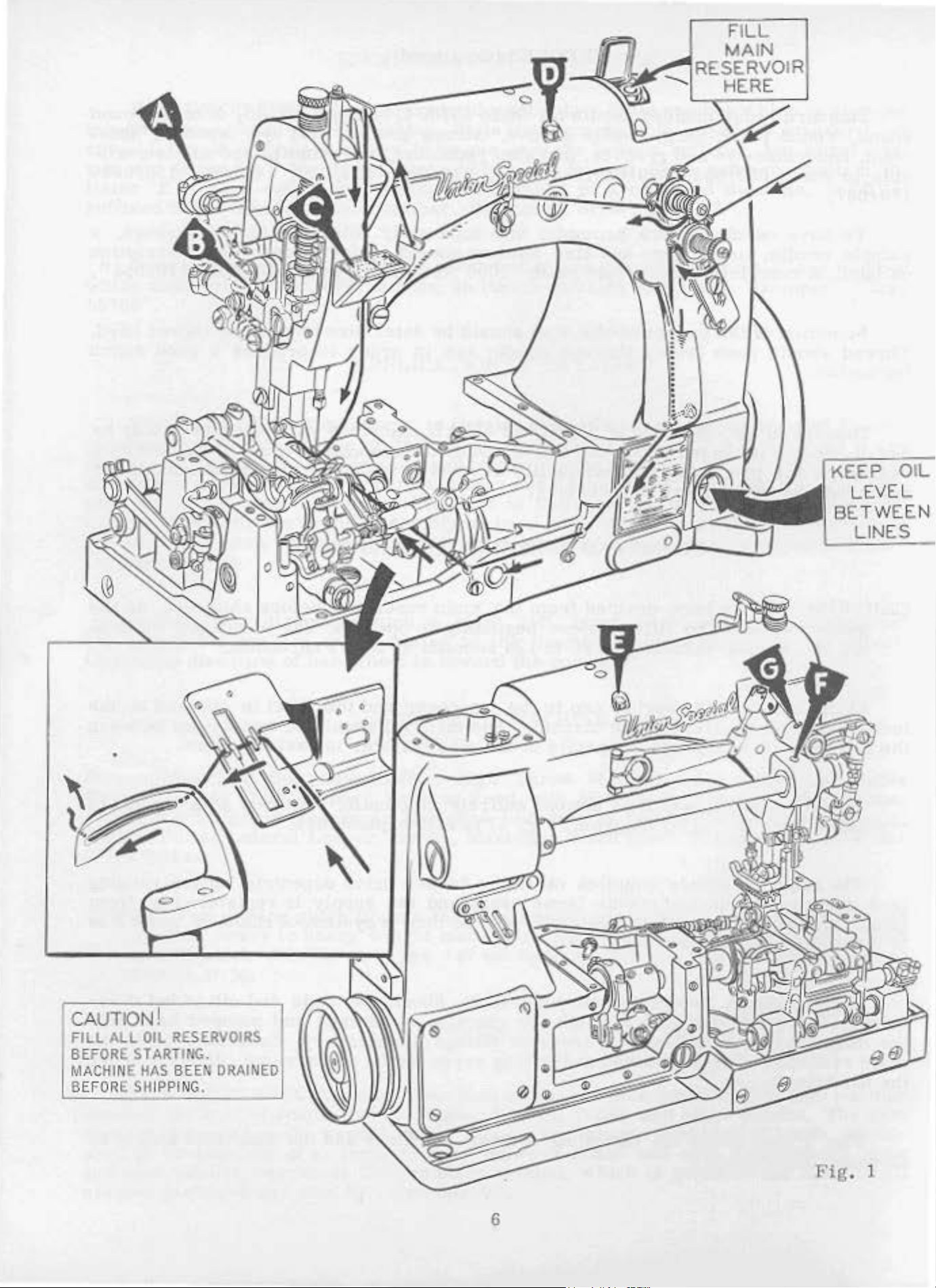
Oil
is
lucile
the
manual
feed
gauge
red
The
The
drive
lines
lubrication
oiling.
main
gauge. The
in
the
main
Oil
has
must
filled
on
on
at
the
this
The
reservoir
eccentric
entire
frame
been
be
viscosity
the
front
drained
filled
spring
of
the
before
of
cap
machine.
gauge. Capacity
,
which
oiling
is
almost
diagram
supplies
and
lower
by
this
needle
mechanism
reservoir
from
90
to
in
(Fig.
oil
lever
.
the
main
beginning
125
the
seconds
top
The
of
the
oil
entirely
1)
is
to
the
crank
is
served
reservoir
to
operate.
at J 00°
cover
oil
level
reservoir
and
should
Fahrenheit.
the
is
automatic,
self-explanatory.
looper
and
thru
drive
the
a
eccentric,
supply
system
before
shipment,
Use a straight
level
be
twelve
requires
is
checked
maintained
ounces.
a
upper
is
registered
of
channels
so
mineral
at
between
minimum
running
at
front
and
wicks
the
the
of
A
daily
quired. Oil
the
main
mnin
the
reservoir
handwheel.
Fig.
threaded
check,
which
has
reservoir
may
1
also
shows
accordingly
before
gone
making
be
drained
the
.
the
morning
through
too
frequent
at
the
threading
start, should
the
machine
oilings
plug
of
screw
these
5
is
filtered
urmecessary
in
the
machines
be
main
and
made
and
.
frame,
the
and
oil
added
pumped
Excessive
directly
machines
if
back
oil
into
in
under
should
re-
the
be
Page 2
MAIN
RESERVOI
HERE
KEEP
LE.VE.L
BE
TW
EEN
CAUTION I
FILL
ALL
OIL
RESERVOIRS
BEFORE
MACHINE
B
EFORE SHIPPING.
STARTING.
HAS
BEEN
DRAINED
_j
I
6
Fig
. 1
Page 3
SYNCHRONIZING
LOOPER
AND
NEEDLE
~OTIONS
Check
21227
AC
Insert
gauge plate
the
indicator
pointer
in
the
gauge
top
of
screw
the
pin
the
indicator
scale
in the
rear
NOTE
to
operating
plate
the
and
again
is
allowable.
operating
.
If
t
he
:
If
follows:
Insert
direction
of
the
then
the
turn
left
height
variation
point
of
move
acts
the
until
needle.
and
of
the
of . 005
the
the
looper
reverse.
the
synchronization
as
follows:
the
pin,
on
the
portion
the
right,
and
needle
note
indicator
contacts
will
reading
gauge
the
looper
the
Note
handwh
is
even
eye
looper
which
throat
but
direction
set
the
bar
is
plate
of
the
do
not
until
indicator
and
the
included
gauge
reading.
the
plate.
return
If
the
to
the
reading
direction, the
is
lower,
No.
eel
drive
21227
in
point
the
height
in
the
with
of
the
needle
inch
is
greater
is
lever
Moving
AC
the
of
the
reverse
the
left
allowable.
of
the
of
scat
tighten
the
so
right
lf
same
is
looper
the
is
not
looper
looper,
of
the
side
with
when
rocker
looper
the
looper
with
using
in
the
the
the
pin
in
that
end
Turn
the
the
of
the
motions
reading.
higher
drive lever
rocker
available,
rocker
moving
eye
of
direction
of
the
resp
If
the
ect
the
handwheelis
to
the
drive
and
the
gauge,
throat
need
set
the
le
screw
looper
left
the
pointer
handwhecl
are
1\
on
the
will
have to
synchronization
and
turn
to
the
needle
unt
needle.
to
the
distance
rear.
lever
needle
in
the
plate
thread
at
screws
take
this
rocker
end
of
the
rests
in
in
synchronization,
variation
scale
rocker
when
will
be
the
handwheel
the
left,
with
il
the
looper
If
the
looper
from
turned
~oving
rocker
is
motions.
looper
rocker.
for
-up
time.
wire
Turn
contacts
pointer
at
"0".
the
reverse
of
one
graduation
the
handwheel
have
moved
to
to
may
is
even
respect
to
point
motions
point
the
in
it
in
will
eye
of
the
operating
the
opposite
accomplished
using
gauge
Place
attaching. Place
hole
the
the
rests
Tighten
direction
the
with
handwheel
edge
of
against
the
until
pointer
on
is
turned
be
moved to
the
front.
be
checked
in
the
operating
with
the
synchron
the
the
looper
again
be
the
needle
left
side
point,
moves
ize,
same
to
direction,
direction
as
follows:
No.
the
the
the
the
set
of
the
the
as
to
the
. A
the
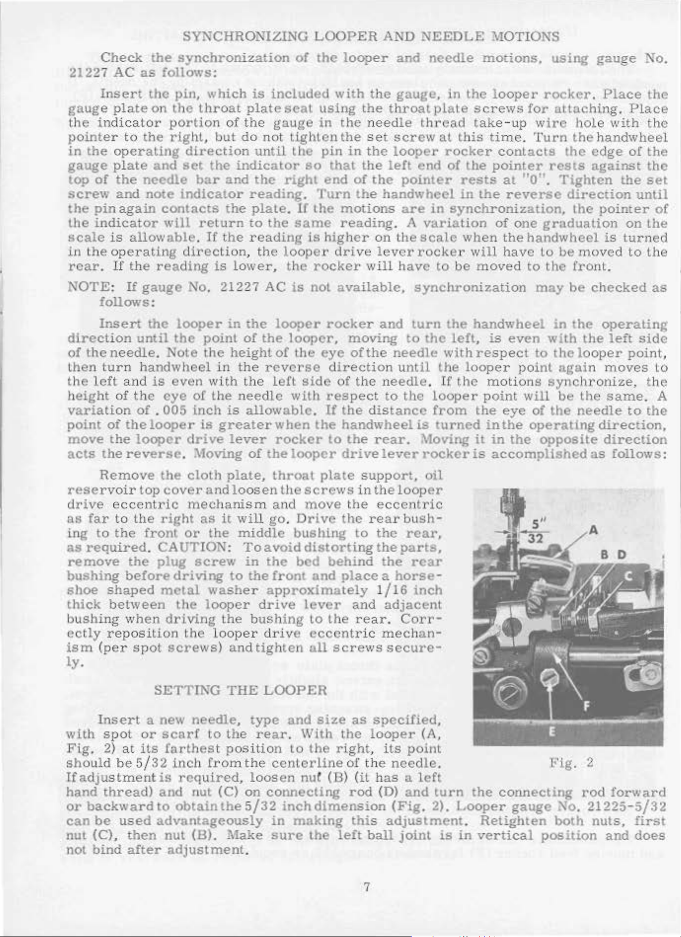
Remove
reservoir
drive
as
ing
as
eccentri
far
to
to
the
required
remove
bushing
shoe
thick
shaped
between
bushing
ectly
ism
ly
reposition
(per
.
Insert
with
Fig.
should
If
hand
or
can
nut
not
spot
2)
be
adju
stment
thread)
backward
be
(C),
bind
the
top
cover
the
right
front
. CAUTION:
the
plug
before
metal
when
spot
driving
screws)
SETTING
a new
or
scarf
at
its
farthest
5/32
is
and
to
used
advantageously
then
after
nut
adjustment.
cloth
and loosen
c
mechanism
as
it
or
the
screw
driving
washer
the
looper
the
the
looper
needle,
to
inch
from
required,
nut (C)
obtain
the
(B). .Make
plate,
throat
and
will go.
middle
To
avoid
in
the
to
the
front
approximately
d!'ive
bushing
driv
and
tighten
THE
LOOPER
type
the
rear. With
position
the
centerline
loosen
on
connecting
5/32
in
sure
the
screws
move
Drive
bushing
distorting
bed
and
lever
to
e
eccentr
all
and
to
the
nut (B)
inch
dimension
making
the
plate
support,
in
the
the
rear
to
the
eccentric
the
the
behind
place a horse-
1
and
the
rear
ic
scre
size
as
the
ws
specified,
looper
right, its
of
the
(it
has a left
rod
(D)
this
left
ball
oil
looper
bush-
rear,
parts,
the
rear
/16
inch
adjacent
.
Corr-
mechan-
secure-
(A,
point
needle.
and
(Fig.
turn
2).
adjustment.
joint
is
the
connecting
Looper
Retighten
in
vertical
gauge
position
Fig.
'lo.
both
2
rod
forward
21225 -
nuts,
and
5/32
fir:;t
does
7
Page 4

SETTING
THE
LOOPER
(Continued)
The
needle,
looper
when
adjustment
reposition
its
is
necessary
looper
is
set
correctl
point passes
,
as
requi
red and
loo
sen
y
in-line-of-feed, as
as close
screw
retighten
as
possible
(
E,
Fig.
screw
it
without
2)
in
(El.
moves to
the
left
contacting the
looper rock shaft
behind
needle.
arm
the
If
(F).
needle.
(B)
up
all
sides.
above
Height
or
Set
the
if
the
can
supporting
dog
hold
er
ance can
right
or
left, as
Fig
. 3
adjustm
down
See
throat
be
as
feed
that the
set
do
plate
screw
adj
usting sc
be
set by loosen
required
ent is
required
g (A,
tips of
and
by
loosening
(C).
Parallelism
rew
necessary
and
retighten
SETTL.'IG
Fig. 4)
the
are
parallel
feed
(A,
Fig
ing
screws
.
,
loosen
THE
in
the
teeth ex
dog
can
. 5),
(E,
SETTI
NG
The
when
the
er
screw
the
underside
poi
nt
scr
ew (A,
(A).
FEED
throat
plate
tend slightly
with
the
thr
attaching
be
set
by
loosening
as
required
Fig. 4)
and
HEIGHT
height
top
or
or
is
flush
Fig. 3)
DOG
so there
less
oat
plate
screw
and
moving
Fig.
OF
of
the
its
eye
the
looper,
with
and
is
than
at
high
(B)
and
nul (D)
retighten
feed rock
4
NEEDLE
needle
is
1/64
when
the
left
side
move
equal
clear
the depth
point
adjusting
and
rotating
nut. Side
er
BAR
is
correct
inch
the
below
loop
of
the
needle ba
ance
of
a t
ooth
of
trave
feed
dog
feed
clear
(F)
to
the
r
on
l.
-
l\OTE:
and moving
Whenever
feed
End
clea
rocker
rance
feed
the
arm
(G)
can be
rocker
feed
docs
(F)
rocker
not
set by
forward
has
been
bind
looseni
.
ng
or backward as
8
moved,
scre
ws
always
(1-D
In
the
required.
check
feed
to
rock
assure
er
that
arm
the
(G)
Page 5

INITIAL
SETTINGS
OF
UPPE
.R
RUNNING
FEE
D
MECHAN
ISM
The
first
the
turned
NOTE
screw
needle
in
: T
mechanism
centerline
of
the
upper
inch
(Fig.
The
should
(B).
if
required
Th
be
is
top
the
he
Fig
of
6)
bell
set
con
.
feed
inthe
bar
has ris
operating
next
. 5
the link
feed
.
Retighten
crank
all
necting
eccentric
eccentric
en
two
paragraphs
which
pin
drive
lever
the
way
rod
assembly
will
1/4 inch
direction.
can
be lowered
Turn
in
the
r e c t i
needle
bot
tom
While
handwhee
the
upper
driving
Fig.
ing
nut
tance
(C)
and the
rock
nut
(
B).
shaft
ball join
to
the
can
also
should
be
in
aperpendicularposition
from
refer
to
later
handwheel
operating
on
u n t i 1
bar
of
its
is
str
holding
l,
position
feed
l
ever
6)
after
(B)
loosen-
so
the
between
centerline
(D)
t
(A,
Fig.
right
in the
be lengthened
the
at
dis
is
be
bottom
lhe
maximum
to
dithe
the
ok
e.
the
lift
(A,
-
t
he
7/8
7)
slot
located
of its
suit
sewing
.
of the
or
shortened
on
the
stroke
height
conditions
upper
to
main
to
,
setting
the
with
shaft
main
the
of
.
Fig.
feed
6
bell
suit sewing
so
that
shaft
when
handwhee
the top
cranl< l
ever
conditions
the
l
feed
Fig.
As the
from
the
between
8)
e111d
the
be
1 3/32
made
ward
by loosening
or
needle
bottom
the
rear
front
of
inch
rearward
of
of
the
(Fig
7
bar
its
the
upper
. 8).
screw
as
requi
just
stroke,
needle
begins
the distance
bar
feed bar (B)
Adjustment
(C)
in
red
and
to
( ,~
,
should
can
the
upper
retighten
rise
Fig
9
.
be
feed
driving
screw
(C).
lever
Fig
(D)
. 8
and
moving
it for -
Page 6

INITIAL
SETTINGS
OF
UPPER
RUNNING
FEED
MECHANISM
(Continued)
Synchronizing
ing
nut
lever
(B).
Set
contact
ward
point
missible.
its
vertical
needle,
left, is
forward
needle
To
raise
and
wise
er
ly
turn
to
set
the
(A,
Fig.
Retighten
Fig
the
the
rear
of
It
face
until
even
or
backward,
guard
or
screw
9)
. 9
rear
of
travel.
should
approach
the
point
with
as
lower
(E)
and
nut
needle
the
A
be
the
required
the
clockwise
raise. Retighten
.
upper
moving
.
guard
needle
clearance
set
as
within
of
the
needle
merely
needle
screw
feed
with
the
Set
the
ball
the
complished
left
hand
(B).
and
the
Turning
turning
stitch
NOTE:
corr
thread)
.
Any
esponding
setting
f
eed
mechanism
SETTING
(A,
(B)
low
Fig
when
of
.
as
possible,
about
looper
.
To
(C),
move
loosen
and
retighten
guard, loosen
to lower
(D)
after
lower
stud
in
feed
the
upper
CI!ANCI:-JG
stitch
by
screw
It
in a counterclockw
change
to
the
loosening
and
turning
(B)
in
stitch length
change
and
also
synchr
as
.
ll)
at
Its
005
inch
3/64
moving
needle
screw
TllE
horizontally
most
inch
(D),
is
yet
REAR
for-
per-
have
or
to
guard
move
screw
screw
or
counterclock
gu
ard
is
prop
can
be
feed
STITCH
required
locknut
the
clockwise
in the
onization
described
NEEDLE
so
the
the
(D) .
(0)
-
-
accomplished
driving
shaft
LENGTH
length. This
(A.
stitch
Fig.
adJUSting
shortens
ise
direction
will
rear
of
necessitate
needle
the
upper
previously.
GUARD
that
it
does
Fig
by
loosen-
segment
10)
(it
the
lengthens
not
. 10
is
ac-
has
a
screw
stitch
a
guard
running
quite
foot
has
Fig.
reached
11
its
highest
position
SF.TTINC
Set
that
it
point
just
may
past
brush,
needle
meet
needle
needle
screws
required
lower
(J),
screws
'T'he
ly
when
is
raised
travel
.
the
front
barely
of
the
looper
the
left
but
guard
this
guard
should
condition
or
guard
(G) ,
rotate
and
or
rotate
reposition
after guard
TliRE
I\D T ENSION
thread
it
begins
to
within 1/8
and
is
entirely
FRON
T
needle
NEEDL
guard
contacts the
(C),
side
not
pick
be
looper
forward
moving
of
the
at
set
yet
at
or
not
needle
retigh
ten
needle
as
is
tens
ion
to
function
screw
guar
necess
properly
release
inch
released
E GUARD
(F,
needle
(B)
to
needle. The
the
needle. The
as
low
as
contact
any
time.
rearward,
guard
holder
s (G).
d,
loosen
ary
and
set.
RELEASE
is
set
as
the
presser
of
the
when
Fig
.
11)
until
the
left,
looper
possible
the
To
loosen
(H)
To
raise,
screws
retighten
correct-
end
the
presser
so
the
is
front
to
rear
move
as
foot
or
its
10
Page 7

If
adjustment
at
the
back
of the
screw. After
THREAD
is
needed, loosen
machine
adjustment
SE
TT
ING HEIGHT
and
there
TENSION
tension
move
should
OF
tension
be no
PRESSER
RELEASE
release
disc
bindi
separator
ng
BAH
(Co
ntinue
d)
levers crew
as
at
any
poin
(A,
Fig
. 12
),
located
required. Retighten
t.
•
The
it
is
possible
(B,
Fig
mately
t
he
lifter
feed
foot
bar
resting
throat
If
ion unt
Fig
.
3),
su
rfa
ce, pry up
driver
heig
ht
to
. 12)
1/16
(F)
plate
is
inch clearan
link
(D, Fig
when
on
the
.
adjustment
il
the
needle
then
, while hold
pre
to
obtain
of
the
presser
rem
fully
ove
depressed
.
the
foot lifter
throat plate,
is nec
sse
the
bar
r b
1/ 16
essary,
is
ba
the
presser foot
.
ce
be
tween
3)
and the
lever
with
turnha
in
the
ing
presser
ar
connection
inch
setting
r (C, F
Also,
the
stud
is
the feed
ndwheel
low p
osition. Loosen
fo
and
ig.
3)
is
set
when
there
the
foot lif
should
bottom end of the
(E)
locat
ed
in the
released and
dog down below t
in
opera
ot
down
and
guide (H)
ret
into the
piece
(Fig
machines
on
the
with a screw
ighten
Draw
screws
the
machine
of
fabric. Refer
. 1) for m
.
correctly
ter
lever
be
app
roxi
slot
upper
the
presser
ting
throat
scre
direct
ws
pla
.
THR
EADING
looper
and sta
anner
if
-
of
he
-
(G.
te
Fig
and
needle threads
r t operating on
to threading
of
threading
.
12
diagram
th
ese
a
•
I
Set
to
the
need
le
The
tha
t the l
comes
q
uired
finge
r h
the
needle
machine
thread
looper
ooper
up
out of
byl
oos
as
been
Fig
.
13
thread
base and
is desired
SETTING
thread
thread
the
mater
ening
screws (Band
pro
perly
frame
midway
in
the
eyelet
in
stitch
LOOPER
retainer
is
cast-off
ial.
finger
Co-ordinated
set, retighten
(A, F
even
bar thre
is
setting
or rai
(C,
its
mo
unting slot.
or
r a
THR EAD
(A,
Fig
just
C).
after
After
screws.
SETTING
WIRE Al:II
Set
ig.
with t
at
the bottom
se
Fig
. 13)
ise
for
NEEDLE
TI
the
ad
13)
he
eyelet
needle
so
that its
top
of its str
for
it
a
for
small
a l
perpendicular
Lower
les
s .
if
FRA
of
arger loop.
TAKE-UP
. 14) sho
the eye of
positioning
uld
the
can
be
needle
be
looperthreadretainer
THREAD
ME
EYELET
thread take-up
upper sur
the hole
(B)
when
in
the
oke.
er
nee
dle
more
set
so
ac-
TAKE-UP
wire
face
the
needle
needle
Lo
wer
thre
bar
thi
ad loop
is
s
<
Hegulate
that
w
ing
reverse
it
exerts
ork
unif
ormly
it clockwise increases
.
the
only enough
PRESSER
presser
when a slight
FOOT
spring
regula
pressure
tension
the
pressure,
PRESSURE
ting
on the
is
placed
co
11
screw
presser
on
(D,
Fig
foot to feed
the fabr
unterclockwise
. 13)
ic. Tur
acts
so
the
n-
the
Fig
.
14
Page 8

12
Page 9

The
that
parts
are
illustrated
used
on
Style
on
the
53700
preceding
C,
but
not
page
used
and
described
on
Style
be
53700
low
B.
represent
the
parts
•
Those
to
Use
this
Reference
indented
assembly.
Ref.
No.
1 77
2
3
4
5
6
7
8
9
10
11
12
13
14
15
16
17
18
19 51
20
21
22
23
24
25
26
27 51281
28
29
30
parts
Styles
Catalog
catalog.
53754
53754
55235
55235
41336
53720
53726
53753
53726
53705
53724
53770
22799
512
51236
5372 2 A
29476
22559
51 325
51242
21 657 E
22517 B
53701 A
53700
nu
descriptions,
Part
No.
6042
78
376
21-335
236
36
24
shown
No. 100 L
mbers
K
in
Band
phantom
that
J
D
A
E
c
B
E
J
D
B
A
B
E
F
G
•
DD
E
L
U-207
s
views
C.
(Style
are
indicate
Screw,
Upper
Upper
Link
PresserFoot
Top
Lower
Screw,
Throat
Feed
Feed
Main
Crank
Looper
Washer, for
Cloth
Washer
Edge
Screw, for
Cloth
537 00 B)
inside
they
for
Running
Running
L<>cking
Locking
Locking
Pin
-----
Scr~v
Feed
Top
Top
Chain
Spr
Scr~v-
Crank
Ferru
Crank
Shaft
Screw
Plate
Guide--
Plate
-----------
Dog
Feed
Feed
Feed
for
Plate-
Cutting
u1g -
l e
---------
Shaft
--- ---
Needle
--
---------
and
a
link
Stud----Stud
Stud
----
Dog
feed
---------
------
-----------
Link
----
Stud
Assembly
No. 53754 F
Cover
-----------
edge
(not
bearing
for
all
bracket
are
pin
Feed Lift
Feed
-----------
Assembly
Dog
Dog,
Guard-------
shown
component
Description
No.
Lift
--------
Washer
Nut -
------
, 14
dog ----
Knife,
Assembly
------
----------
--------
--------------
guide
------
------
Shank
marked "FH
teeth
---------
------, .
-----------
-------on
no
parts
or
41336 C ---
Driving
Driving
----
----------
---
--
---------
-----marked
------
-----------
990
---
---
-----
picture
reference
not
illustrated
box
------
-------
per
----
on
the
parts
------
Link-------
Lever
-------
----------
---------
----------
------
---------
--
----
inch-
-----------
-------
----------
-----
--------inch
---------
--
-----
------
-------- --------
"--
-----
---------
-------
"L"
-----
-----
----------throw
--------
- -
--------
-----
- -
----
------plate)
numbers
picture
of
a
complete
----------
-----
----------
------
------
-----
------
----------
- -·
----------
----------
-----
-----
-----------
-----------
------
---------
-----
----------
------
---
------
--
-------
-----
-------------
------
--------
--
------
-------
are
common
or
described
plate
---------
----------
---------
------
---------
------
--------
------
----------
----------
--------
--
--------
------
and
-----
-------
----
-- --
-------
----
------
------
------
-------
----
-----
------
part
Amt
--
- -- 1
---
---
- 1
---
--
- - - 1
---
in
have
or
.
Req.
1
1
1
1
1
1
1
2
1
1
1
1
1
1
1
1
1
1
1
1
2
1
2
1
2
1
1
1
•
•
'
'
13
 Loading...