

Page 1

STYLES
53100A
53100B
53100C
53100D
53100E
ADJUSTING INSTRUCTIONS AND
ILLUSTRATED PARTS LIST
CLASS 53100
STREAMLINED HIGH SPEED ZIG-ZAG
MACHINES
CATALOG NO.
112R-GR
FIRST EDITION
06/10/08
Page 2

MANUAL NO. 112R-GR ADJUSTING INSTRUCTIONS AND LLUSTRATED PARTS LIST FOR 53100 SERIES MACHINES
First Edition Copyright 2007
BY
Union Special Corporation Rights Reserved In All Countries
Printed in U.S.A. Jan 2007
FOREWORD
The 5000 series streamlined zig - zag machines covered by this catalog represent the latest design of the UNION SPECIAL
flat bed line. Class 53100 machines offer many advantages on various operations on a variety of garments such as
nightgowns, slips, panties, foundations, children's knit undergarmrnts, men's trousers, women's dresses, blouses, bed jakets
and pajamas.
Light weight presser bar and needle bar driving mechanism make it possible to attain the utmost in speed and production.
The new light weight parts and needle bearings make them lighter running and smoother operating. The light weight presser
bar mechanism reduces pressure required to lift the presser foot.
Automatic lubrication and a new filter type oil return pump, used in conjunction with isolated mounting oil pan base plate,
for returning filtered oil to the main reservoir, has made maintenance simple.
It is our constant aim to furnish carefully prepared information which will enable our customers to secure all possible
advantages from the use of UNION SPECIAL machines. The following pages illustrate and describe the parts used in all of
the machines covered in this catalog.
Union Special representatives will be found in all manufacturing centers, ready to cooperate with you to plan and estimate
requirements.
CONTENTS
IDENTIFICATION OF MACHINE .................................................................................................................................................................3
APPLICATION OF CATALOG ...................................................................................................................................................................3
STYLES OF MACHINE ................................................................................................................................................................................3
NEEDLES .................................................................................................................................................................................................... 4
ORDERING REPAIR PARTS ........................................................................................................................................................................4
ORDERING REPAIR PARTS (CONTINUED) ................................................................................................................................................ 5
IDENTIFYING PARTS ................................................................................................................................................................................... 5
USE GENUINE NEEDLES AND REPAIR PARTS ........................................................................................................................................... 5
TERMS ........................................................................................................................................................................................................ 5
OILING AND THREADING ......................................................................................................................................................................... 5
0ILING AND THREADING DIAGRAM ....................................................................................................................................................... 6
SELF-PRIMING HEAD OIL SIPHON ............................................................................................................................................................ 7
INSTALLING AND MAINTENANCE OF OIL SIPHON ................................................................................................................................. 7
INSTRUCTIONS FOR MECHANICS ............................................................................................................................................................ 8
NEEDLE LEVER STUD SETTING ...................................................................................................................................................................8
OILING SYSTEM ......................................................................................................................................................................................... 8
SETTING THE ZIG-ZAG MOTION ............................................................................................................................................................... 8
SPACING NEEDLE IN THROAT PLATE .......................................................................................................................................................8
SETTING THE LOOPER ...............................................................................................................................................................................8
SETTING THE LOOPER (CONTINUED) .......................................................................................................................................................9
SETTING HEIGHT OF NEEDLE BAR ............................................................................................................................................................. 9
SYNCHRONIZING LOOPER AND ............................................................................................................................................................. 9
NEEDLE MOTIONS ..................................................................................................................................................................................... 9
SYNCHRONIZING LOOPER AND ........................................................................................................................................................... 10
NEEDLE MOTIONS (CONTINUED) ..........................................................................................................................................................10
SETTING THE FEED DOG ......................................................................................................................................................................... 10
SETTING THE FEED DOG (CONTINUED) .................................................................................................................................................11
CHANGING STITCH LENGTH .................................................................................................................................................................. 11
SETTING THE NEEDLE GUARD ................................................................................................................................................................. 11
SYNCHRONIZATION OF THE UPPER ROLLER FEED ................................................................................................................................ 12
THREADING .............................................................................................................................................................................................12
SETTING THE LOOPER THREAD TAKE-UP ................................................................................................................................................13
THREAD TENSIONS .................................................................................................................................................................................. 13
PRESSER FOOT PRESSURE ....................................................................................................................................................................... 13
SETTING NEEDLE THREAD TAKE-UP ........................................................................................................................................................ 13
2
Page 3

SETTING SPRING RETAINERS ON LOOPER .............................................................................................................................................14
THREAD TENSION RELEASE .....................................................................................................................................................................14
SETTING THE ATTACHMENTS ................................................................................................................................................................... 14
MAIN FRAME, CAST-OFF PLATE, MISCELLANEOUS COVERS AND PLATES ......................................................................................... 17
CLOTH PLATES, CLOTH PLATE COVERS, MISCELLANEOUS AND ATTACHMENTS .............................................................................. 19
MAIN FRAME, BUSHINGS AND MISCELLANEOUS OILING PARTS ........................................................................................................ 21
FOR STYLES 53100B AND C ONLY CLUTCH ASSEMBLY, CLUTCH DRIVE SHAFT GEAR AND HOUSING ASSEMBLY .......................... 23
FOR STYLES 53100B AND C ONLY CLUTCH ASSEMBLY, CLUTCH DRIVE SHAFT GEAR AND HOUSING ASSEMBLY .......................... 25
CRANKSHAFT, NEEDLE LEVER AND LOOPER DRIVING PARTS ............................................................................................................ 27
CRANKSHAFT, NEEDLE LEVER AND LOOPER DRIVING PARTS ............................................................................................................ 29
LOOPER ROCKER AND CONNECTING ROD PARTS ............................................................................................................................ 31
MAIN SHAFT AND FEED MECHANISM ................................................................................................................................................... 33
FOR STYLE 53100E ONLY MAIN SHAFT AND FEED MECHANISM ......................................................................................................... 35
THREAD TENSION AND FOOT LIFTER LEVER PARTS ............................................................................................................................... 37
FEED DOGS, THROAT PLATES AND PRESSER FEET ................................................................................................................................ 39
THREAD STAND, KNEE PRESS AND TAPE REEL PARTS ........................................................................................................................... 41
IDENTIFICATION OF MACHINE
Each UNION SPECIAL machine is identified by a Style number which is stamped into the name plate on
the machine. Style numbers are classified as standard and special. Standard Style numbers have one or
more letters suffixed, but never contain the letter “Z”. Example: “Style 53100 A”. Special Style numbers
contain the letter “Z”. When only minor changes are made in a standard machine, a “Z” is suffixed to the
standard Style number. Example: “Style 53100 AZ”.
Styles of machines similar in construction are grouped under a class number which differs from the style
number, in that it contains no letters. Example: “53100”.
APPLICATION OF CATALOG
This catalog applies specifically to the standard Styles of machines as listed herein. It can also be
applied with discretion to some Special Styles of machines in this class. Reference to direction, such
as right, left, front, back, etc., are given from the operator’s position while seated at the machine.
Operating direction of handwheel is toward the operator.
STYLES OF MACHINE
High Speed Streamlined Flat Bed, Single Needle, Medium Throw, Zig-Zag Machine. Lightweight
Presser Bar and Needle Bar Driving Mechanism, Single Reservoir EnclosedAutomatic Lubricating
System, Filter Type Oil Return Pump and Oil Siphon Assembly. Lateral Looper Travel, WorkSpace to
Right of Needle Bar 7 3/4 Inches.
53100A For attaching and mitering lace to nightgowns, slips, and panties made from light to medium
weight knit and woven fabrics of cotton, rayon, nylon, dacron and similar materials; also for
hemming panels on two-way stretch foundations. Can be used for purl edge stitching on
children’s knit undergarments. Knee press for raising presser foot. Seam specification 404LSa-1.
53100B Power driven upper roller feed. For attaching pre-made waistband linings to tops or to
waistband of men’s trousers, giving hand felled effect. Folder No. 23450L prepared to take
waistbands ranging from 1 1/4 to 4 inches wide, in long lengths, entering from the right, and
produces headings of from 1/8 to 3/4 inches. Seam specification 404-LSb-1.
53100C Same as 53100B, except without folder.
53100D Same as 53100 A. except fitted with open toe “V” type presser foot and swing-up edge
guide attached to the lower presser bar bushing, to be used for abutted edge seaming on
slips and gowns. Seam specification 404-FSa-1.
53100E Differential feed machine. For attaching lace to neck, armholes and bottom of nightgowns,
slips, panties, gathering either the garment, lace or both together. Attaching tiers of lace to
slips, dresses and nightgowns. Setting puff sleeves in blouses, bed jackets and pajamas.
For operations on light to medium weight knit and woven fabrics of cotton, rayon, nylon,
dacron and similar materials where a large percent of the work calls for intermittently or
continuously gathered seams. Knee press for raising presser foot. Seam specification 404LSa-1, FSA-I or SSa-1.
3
Page 4

NEEDLES
Each UNION SPECIAL needle has both a type number and a size number. The type number denotes the
kind of shank, point, length, groove, finish and other details. The size number, stamped on the needle
shank, denotes the largest diameter of blade measured in thousandths of an inch midway between the
shank and the eye. Collectively, type number and the size number is the complete symbol.
Standard needle for Styles 53100 A, D and E is Type 163 GAS and the standard needle for Styles 53100
B and C is Type 110 GAS.
Type No. Description and Sizes
110 GAS Round shank, round point, extra short double groove, struck groove, ball
eye long spot government, chromium plated - sizes 090/036, 100/040,
110/044: 125/049.
163 GAS Round shank, round point, Picoetta, single groove, struck groove, flat
blade, long spot, chromium plated - sizes 070/027, 075/029, 080/032,
090/036, 100/040, 110/044, 125/049.
To have needle orders promptly and accurately filled, an empty package,a sample needle, or the type and
size number should be forwarded. Use description on label. A complete order would read: "11000
Needles,Type 110 GAS, Size 110/044".
Selection of the proper needle size should be determined by the size of thread used. Thread should pass
freely through needle eye in order to produce a good stitch formation.
ORDERING REPAIR PARTS
ILLUSTRATIONS
This catalog has been arranged to simplify ordering repair parts. Exploded views of various sections of the
mechanism are shown so that the parts may be seen in their actual position in the machine. On the page
opposite the illustration will be found a listing of the parts with their part numbers, descriptions and the
number of pieces required in the partcular view being shown.
Numbers in the first column are reference numbers only and merely indicate the position. of that part in the
illustration. Reference numbers should never be used in ordering parts. Always use the part number listed
in the second column.
Component parts of sub-assemblies which can be furnished for repairs are indicated by indenting their
descriptions under the description of the main subassembly. Example:
9. 29476LE Looper Driving Lever Crank Assembly ............................................... 1
10. 22559A Screw, lower ......................................................................... 2
11. 51243C Ball Stud Guide ..................................................................... 1
12. 22729 Screw .................................................................................. 1
13. 22587 Screw, upper ......................................................................... 2
It will be noted in the above example that the eccentric and bearing are not listed. The reason is that
replacement of these parts individually is not recommended, so the complete sub-assembly should be
ordered.
In those cases where a part is common to all of the machines covered by this catalog, no specific usage
will be mentioned in the description, however, when the parts for thevarious machines are not the same,
the specific usage will be mentioned in the description, and if necessary, the difference will be shown in
the illustration.
4
Page 5

ORDERING REPAIR PARTS (CONTINUED)
At the back of the book will be found a numerical index of all the parts shown in this book. This will facilitate
locating the illustration and description when only the part number is known.
IDENTIFYING PARTS
Where the construction permits, each part is stamped with its part number. On some of the smaller
parts, and on those where the construction does not permit, an identification letter is stamped in to
distinguish the part from similar ones.
Part numbers represent the same part, regardless of catalog in which they appear.
IMPORTANT! ON ALL ORDERS, PLEASE INCLUDE PART NAME AND STYLE OF MACHINE FOR
WHICH PART IS ORDERED.
USE GENUINE NEEDLES AND REPAIR PARTS
Success in the operation of these machines can be secured only with genuine UNION SPECIAL
Needles and Repair Parts as furnished by the Union Special Corporation, its subsidiaries and
authorized distributors. They are designed according to the most approved scientific principles, and are
made with the utmost precision. Maximum efficiency and durability are assured.
Genuine needles are packaged with labels marked Union Special Genuine repair parts are stamped
with the Union Special trademark, U S Emblem. Each trademark is your guarantee of the highest
quality in materials and workmanship.
TERMS
Prices are strictly net cash and are subject to change without notice. All shipments are forwarded f.o.b.
shipping point. Parcel Post shipments are insured unless otherwise directed. A charge is made to
cover the postage and insurance.
OILING AND THREADING
The oil has been drained from the machine before shipping, and the reservoir must be filled before
beginning to operate. Use a straight mineral oil with a Saybolt viscosity of 90 to 125 seconds at 1000
Fahrenheit.
Oil is filled at the spring cap in the top cover, and the oil level is checked at the sight gauge on the
front of the machine. The oil level should be maintained between the red lines on the gauge. The
capacity of the oil reservoir is 12 ounces.
The machine is automatically lubricated, and no oiling, other than keeping the main reservoir filled is
necessary.
A daily check before the morning start should be made and oil added if required. Oil which has gone
through the machine is filtered and pumped back into the main reservoir, making too frequent oilings
unnecessary. Excessive oil in the main reservoir may be drained at the plug screw in the main frame
directly under the handwheel.
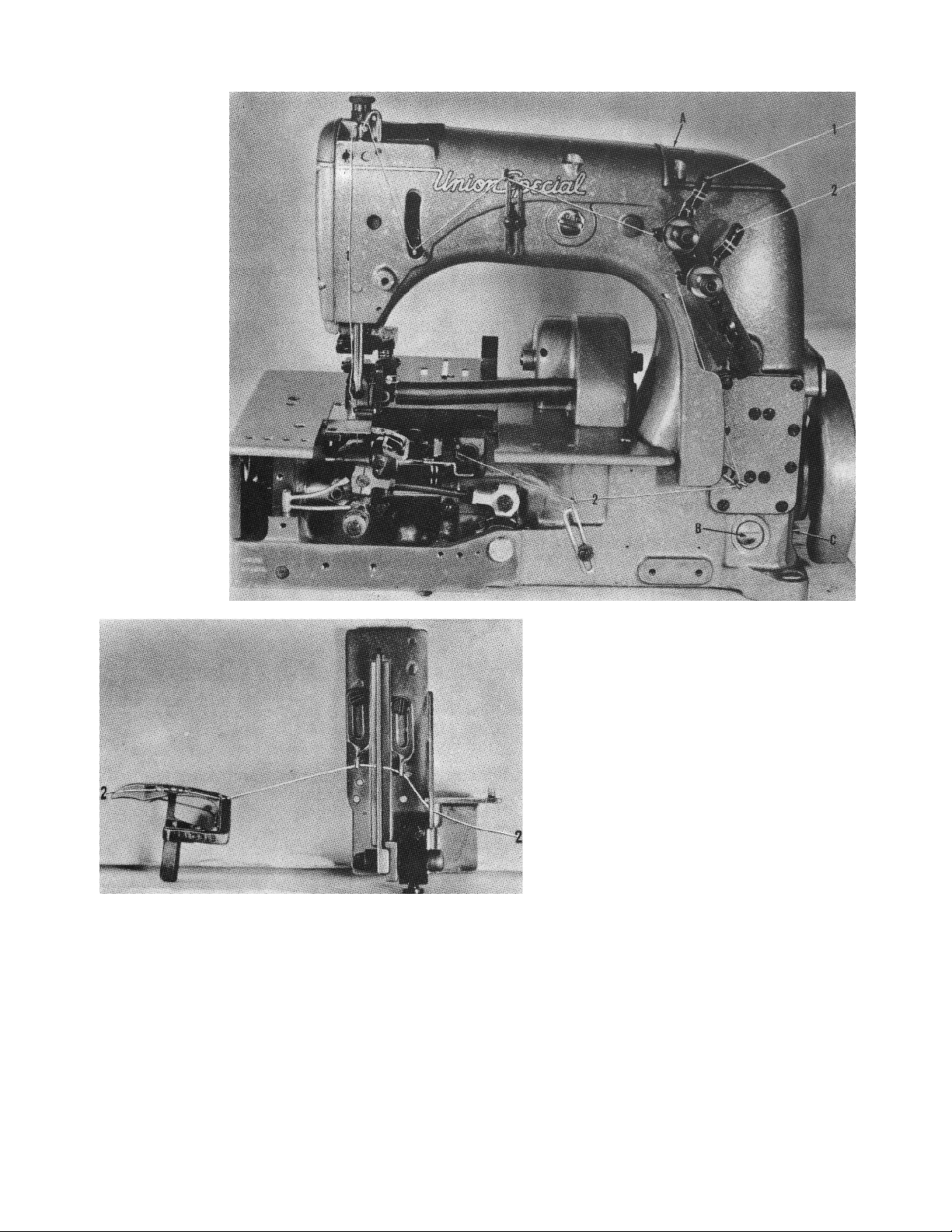
On the next page is a picture showing the manner in which the 5310O Styles covered in this catalog
are threaded. The looper threading has been enlarged for clarity.
5
Page 6
0ILING AND THREADING DIAGRAM
STYLE 53100 C
Oil has been drained from the machine before shipping, and the reservoir must be filled before beginning
to operate. Oil is filled at spring cap (A). Oil level is checked at sight gauge (B). Use a straight mineral
oil with a Saybolt viscosity of 90 to 125 seconds at 10 Fahrenheit. Excessive oil in the main reservoir may
be drained at plug screw (C).
Thread machine as indicated, thread 1 is the needle thread, and thread 2 is the looperthread. The looper
threading at the cast-off plate and looper has been enlarged for clarity.
6
Page 7
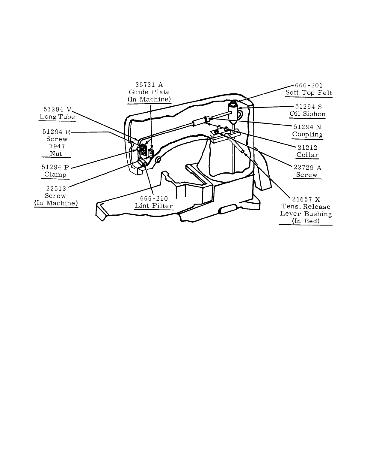
SELF-PRIMING HEAD OIL SIPHON
Class 53100 machines are equipped with a self-priming head oil siphon. When the machine is started, oil
splashes on the priming cupfelts, filters through the felts, and trickles down the vertical oil tube, thus,
priming the siphon. Once the prime is established, it is maintained, unless the felts are removed. The
siphon operates twenty-four hours a day, removing oil at the rate of six to twelve drops per minute, which
of course, far exceeds the rate at which oil collects in the head.
INSTALLING AND MAINTENANCE OF OIL SIPHON
A newly installed siphon starts its action within three to five minutes after the machine is operating.
However, it maybe twenty minutes or so before all the air is removed from the line and the siphon is in full
operation. In Class 53100 machines without a head sump, the head will be free of excess oil by that time.
The felts in the priming cup are designed for a specific purpose. The bottom felt, 666-209, is thin and
relatively dense, to meter the flow of priming oil and to prevent the entrance of air. The softer top felt, 666201, is a filter to prevent the clogging of the metering felt. This felt, at the intake of the siphon, keeps the
siphon clear of lint, and prevents the entrance of air at that point. For the best initial self -priming condition,
the felts of the siphon should be dry. In this condition, it is difficult for air to be trapped between the felts
or in the top soft felt itself.
However, if for some reason the priming cup felts had been oiled before installing, the siphon may fail
because air is trapped between the felts or in the soft top felt. As a precaution, remove the soft felt from
the cup. Then, while squeezing the felt between the fingers, saturate it well with oil. In other words, squeeze
out the air and replace it with oil. Then, completely fill the cup with oil and push or twist the soft felt down
into cup so that it definitely contacts the harder thin felt. This precaution prevents the trapping of air, and
no trouble should be experienced when starting the siphon.
If you want to be doubly sure that the siphon is functioning correctly, on a machine in operation, apply a
certain amount of oil in the sump around the felt in the head. Before doing this, be certain that this felt
has been saturated in the same manner as explained for the soft felt in the top of the siphon cup.
When this is done., the siphoning action will begin, and the oil will be removed as explained.
7
Page 8
INSTRUCTIONS FOR MECHANICS
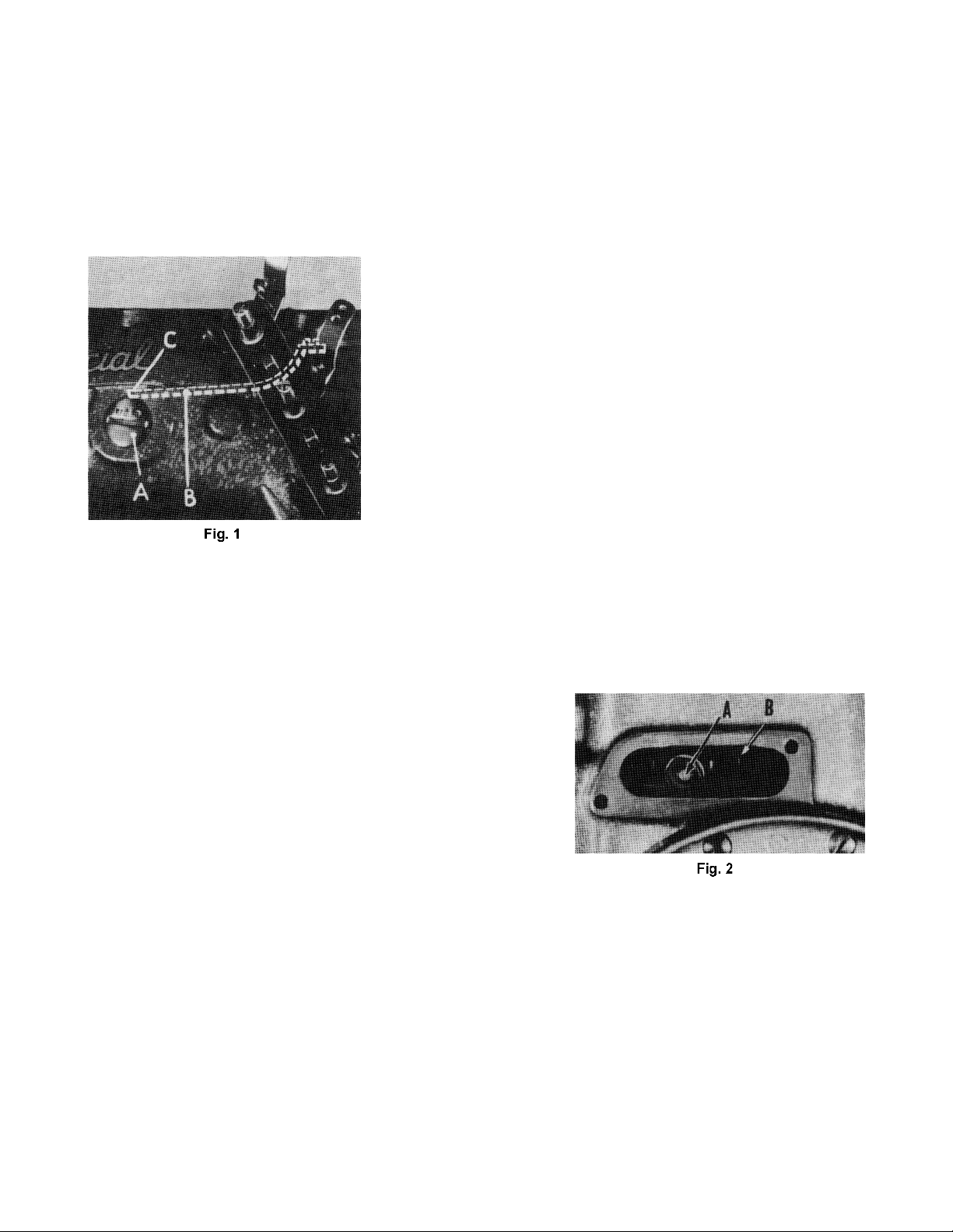
NEEDLE LEVER STUD SETTING
Observe the location of the needle lever stud (A, Fig. 1). The head of the needle lever stud is marked with
an arrow and the word “UP”. These studs are set correctly when the arrow points vertically up. Also check
the position of the needle lever bearing oiler (B) inside the arm casting, which lubricates the needle lever,
stud. Make sure it is tilted downwardly and that its delivery end (C) contacts the inside wall of the bed
casting at the back, just above the notch of the needle lever shaft stop collar. Do not allow the oil tube to
rest on the needle lever.
OILING SYSTEM
Clean machine thoroughly. Fill oiling system to the first red line of
oil gauge on the front of the machine, and oil all bearings. Run
machine slowly for a minute to allow oil wicks to carry oil to the
bearings. Then, recheck oil in oiling system and run machine for
five minutes. Run Styles 53100A, D, and E at 4500 R. P.M. and
Styles 53100B and C at 4000 R.P.M. Inspect siphon and head felt
for proper function, and all plug screws for leakage.
SETTING THE ZIG-ZAG MOTION
Set the zig-zag motion to the maximum travel that the needle hole
in the throat plate will permit.This can be accomplished by moving
the ball joint (A, Fig. 2) in the segment lever (B) located under the
cover directly above the handwheel on the right side of machine.
Moving it away from the operator increases the zig-zag motion
and toward the operator acts the reverse.
The cam gear pinion, located on the crank shaft adjacent to the handwheel housing, should be set so that
the lateral zig-zag motion of the needle bar occurs when the needle is completely out of the work. This is
accomplished by loosening the set screws in the pinion; then, while holding the gear train in a fixed position,
turning the handwheel either forward or backward until the desired timing is obtained.
SPACING NEEDLE IN THROAT PLATE
Equalize the clearance between the needle (A, Fig. 3) and the
right and left sides of the needle hole (B) in throat plate (C). This
is accomplished by loosening set screw (D) and turning the
eccentric stud (E) clockwise or counterclockwise until the
described clearance has been obtained. Retighten set screw.
If additional adjustment is required, it can be obtained by
loosening set screw (A, Fig. 4) and turning the eccentric ball
joint stud (B), located at the right end of the needle bar frame
under the top cover, either clockwise or counterclockwise.
SETTING THE LOOPER
Insert a new needle, size as specified, Type 163GA for Styles 53100A, D, E and Type 110 GA for
Styles 53100B and C.
8
Page 9
SETTING THE LOOPER (CONTINUED)
With the zig-zag motion at the end of its stroke to the right, set the looper (A, Fig.
5) so the distance from the center of the needle (B) to the point of the looper is 5/
32 inch, when the looper is at its farthest position to the right. Looper gauge No.
21225-5/32 (C) can be used advantageously in making this adjustment. If
adjustment is needed, loosen nut (D) (it has a left hand thread) and also loosen
nut on right end of connecting rod (E), turn connecting rod forward or backward
to obtain 5/32 inch and retighten both nuts.
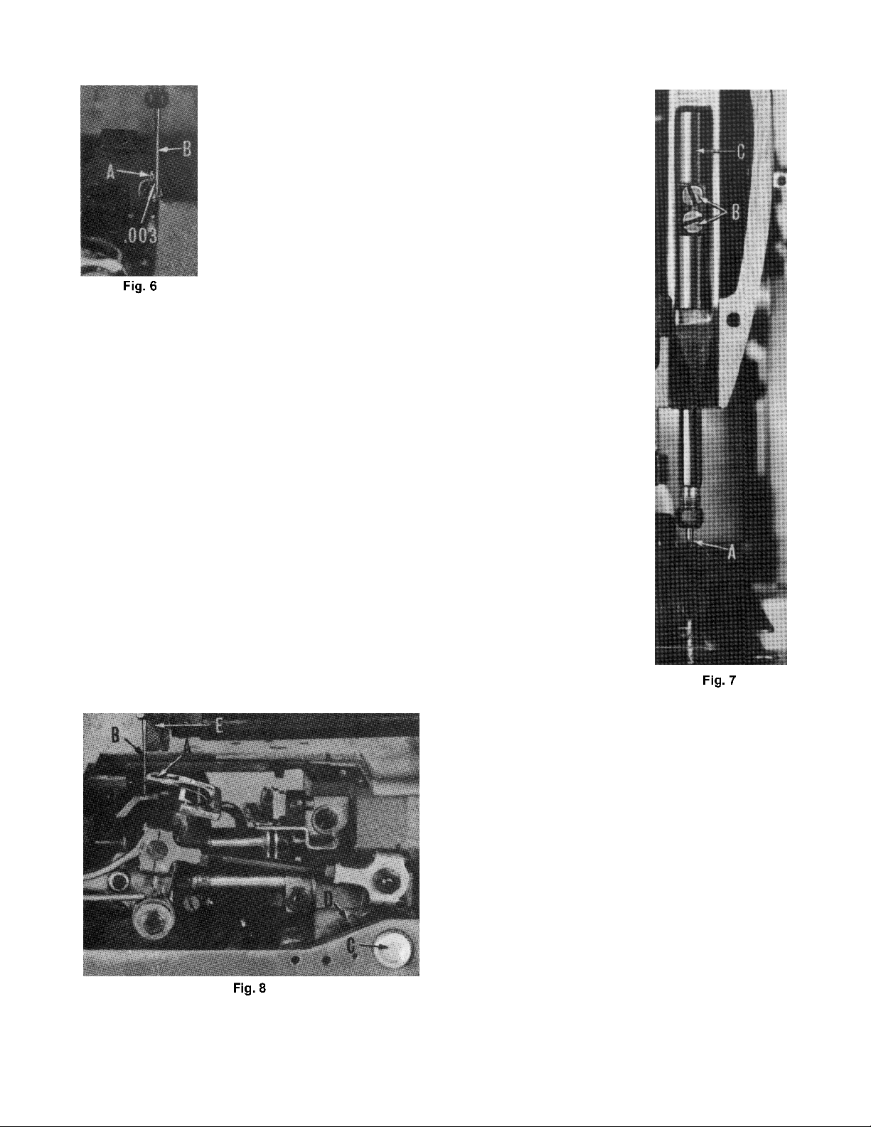
The looper is set correctly in line with the feed when there is .003 inch space
between its point (A, Fig. 6) and the rear of the needle (B) as the former is
ascending on the right side. If adjustment is needed, loosen screw (F, Fig. 5) and
move looper toward or away from needle as required and retighten screw when
.003 inch space is obtained.
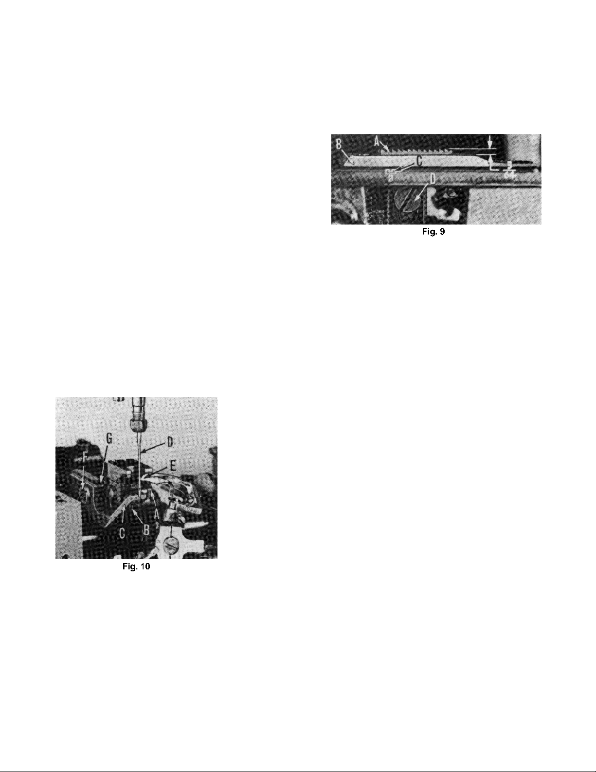
SETTING HEIGHT OF NEEDLE BAR
The height of the needle (A, Fig. 7) is correct when the top of its
eye is 1/64 inch below the underside, of the looper, with the
looper point flush with the left side of the needle and the needle
is ascending on the left side. If adjustment is necessary, loosen
screws (B) and move needle bar (C) up or down as required and
retighten screws.
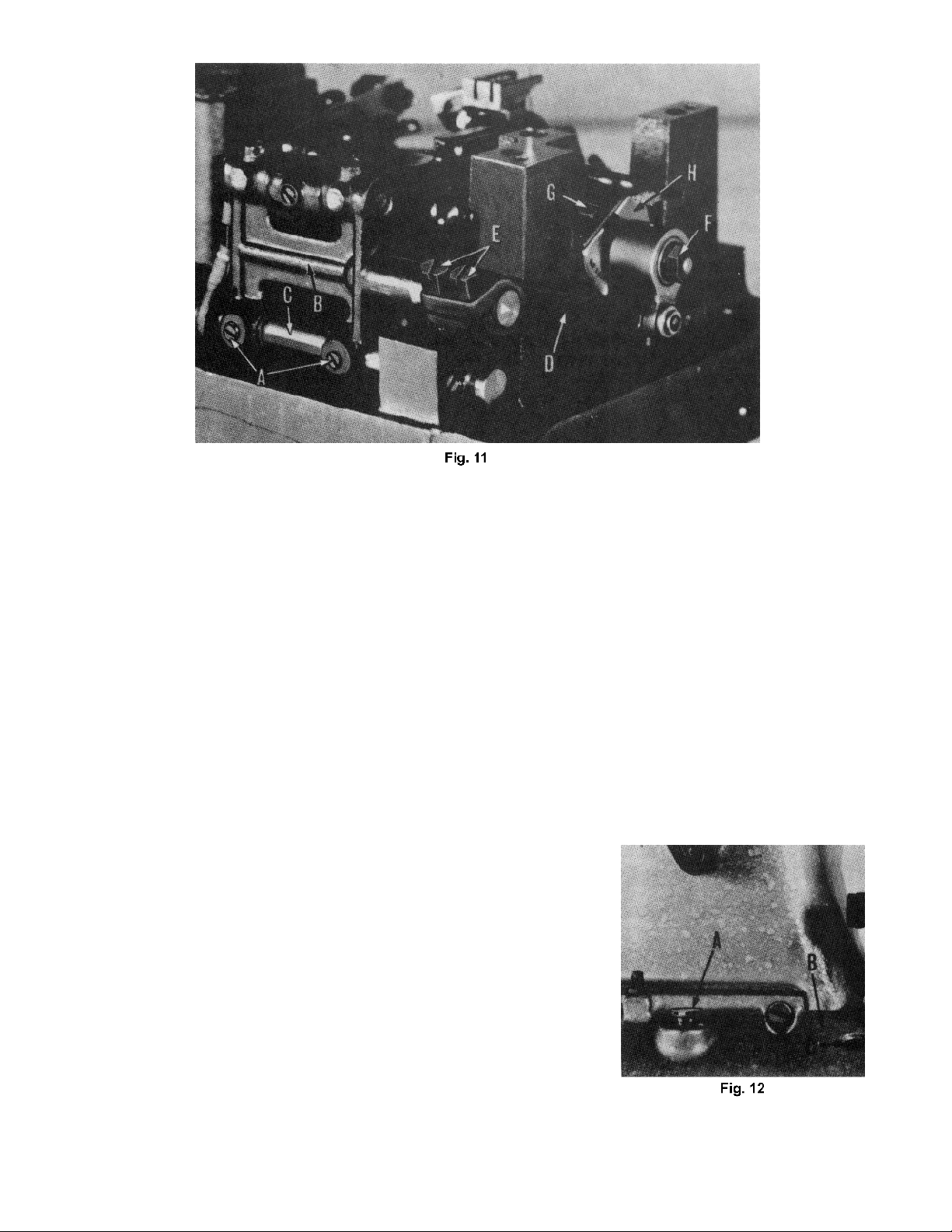
SYNCHRONIZING LOOPER AND
NEEDLE MOTIONS
Turn the handwheel in the operating direction until the looper
point (A, Fig. 8) moves to the left and is even with the left side
of the needle (B). Note the height of the eye of the needle with
respect to the looper point, then, turn the handwheel in the
reverse direction until the looper point again moves to the left, and is even
with the left side of the needle. If the motions synchronize, the height of the
eye of the needle with respect to the looper point will be the same. A
variation of .005 inch is allowable. If the distance from the eye of the needle
to the point of the looper is longest when the pulley is turned in the operating
direction, move the looper drive lever shaft synchronizing stud (C) to the
rear. Moving it in the opposite direction acts the reverse.
Moving of the looper drive lever shaft synchronizing stud is accomplished
as follows: Loosen clamp screw (D) of looper drive lever.
To move stud to rear (away from operator), a light tap with a small hammer,
directly on the stud, is all that is required.
9
Page 10
SYNCHRONIZING LOOPER AND
NEEDLE MOTIONS (CONTINUED)
To move stud forward (toward operator), remove the cloth
plate, oil reservoir top cover, oil reservoir back cover, and on
Styles 53100B and C, remove the clutch drive housing; then,
a light tap on the looper drive lever rocker shaft, toward the
operator, is all that is required.
Then, using the looper drive lever to take up the end play
between the looper drive lever rocker shaft and its
synchronizing stud, tighten the looper drive lever on the shaft
using screw (D, Fig. 8).
Reset the zig-zag motion to maximum that the needle hole in
throat plate will permit (allow . 0 10 to . 0 1 5 inch clearance
between the side of needle and needle hole).
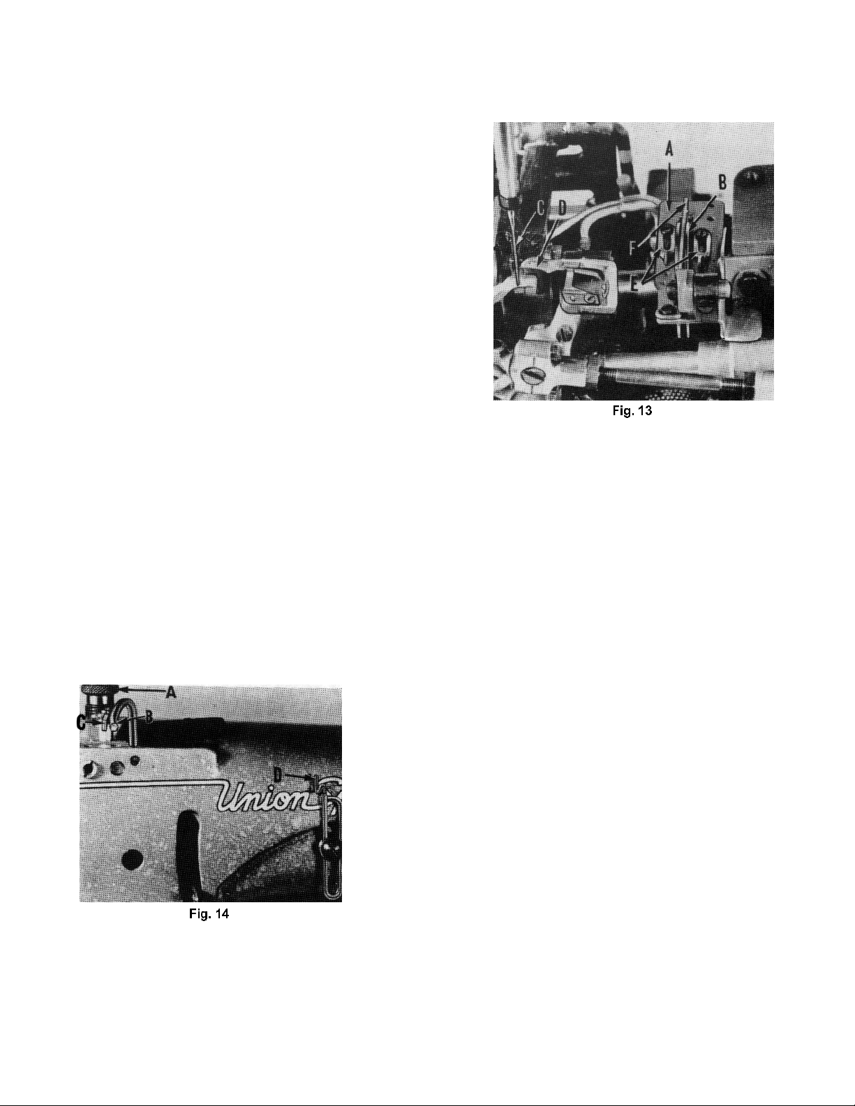
SETTING THE FEED DOG
For Styles 53100 A, B, C and D, set the feed dog (A, Fig. 9) in the throat plate (B)
so there is equal clearance on all sides. See that the tips of the teeth are parallel
with and 3/64 inch above the throat plate at high point of travel. Adjust the
supporting screw (C), under the feed dog, to maintain this setting. Screw (D) is
used to hold feed dog in position.
If feed dog teeth are not parallel with the throat plate, loosen nut (A. Fig. 10) and
turn screw (B) clockwise to lower the front teeth, and counterclockwise to raise the
front teeth. Retighten nut when feed dog is set properly.
Should it be necessary to move the feed dog to the left or right, loosen screws (A,
Fig. 1 1) which hold the feed rocker (B) onto the feed rocker shaft (C), and move
feed rocker to desired position and retighten screws. Make sure that the feed
rocker arm (D) does not bind after making this adjustment.
Should it be necessary to move the feed dog forward or backward, loosen screws
(E) which clamp the feed rocker arm to the feed rocker and move the feed rocker
forward or backward as needed, and retighten screws.
For Style 53100E, set the main feed dog so that it is
level with the throat plate, and that at its high position,
it extends the depth of a tooth above the throat plate.
Maintain this adjustment by means of the stop screw
under the feed dog holder.
Space the feed dog laterally, so that there is equal
clearance between the feed prongs and the throat
plate slots. Loosen feed dog holding screws and move
feed dog from side to side for this adjustment. If more
adjustment is needed, the feed dog may be moved
laterally the same as described in paragraph 3.
10
Page 11
SETTING THE FEED DOG (CONTINUED)
With an average stitch length setting, equalize the travel of the feed dog so that, at both ends of its travel,
it is equidistant from the ends of the throat plate slot. Make this adjustment the same as described in
paragraph 4.
Set the height of the differential feed dog to correspond with that of the main feed dog by moving it up or
down in its holder.
Turn handwheel in operating direction until the feed dog is
at its farthest point of travel to the rear, and set the
differential feed so that there is I/ 64 inch clearance
between the center row of teeth and the end of the throat
plate slot. This is done by loosening the two headless
screws which clamp the shank of the differential feed bar.
The throat plate support will have to be removed for
access. Also level the feed during this adjustment.
Set the front stop for the intermittent differential feed lever as far forward in its slot as it will go. Turn the
handwheel in operating direction until the feed dogs are descending. When the tips of their teeth are flush
with the top of the throat plate, manipulate the differential feed control lever up and down. At this point, there
should be no more than 1/ 64 inch motion in the differential feed dog. If more motion exists, loosen the three
screws which hold the segment slot plate to the feed rocker, and manipulate the position of the slot plate
until excess motion of the differential feed dog is eliminated. An offset screw driver will be required for this
adjustment.
Continue to turn the handwheel in operating direction until the feed dog reaches its most forward point of
travel. Depress the differential feed control lever until the front of the differential feed dog just clears the
throat plate slot by I/ 64 inch and set the rear stop for the differential feed control lever against the lever
pointer at this position.
CHANGING STITCH LENGTH
Set the stitch to required length. This is accomplished by
loosening the lock nut (F, Fig. 11) (it has a left hand thread) on
the end of the stitch regulating stud and turning the stitch
adjusting screw (G) located under the left end of the cloth plate,
in the head of the main shaft (H). Turning screw in a clockwise
direction shortens the stitch, and turning screw in a
counterclockwise direction lengthens the stitch.
SETTING THE NEEDLE GUARD
Set the needle guard (C, Fig. 10) horizontally so that it barely
contacts the needle (D). It should be set as low as possible, yet
have its vertical face remain in contact with the needle until the
point of the looper (E), moving to the left, is even with the needle
and the latter is ascending on the left side. To move needle
guard forward or backward, merely loosen screw (F), move needle guard as required, and retighten
screw. To raise or lower needle guard, loosen screw (F), and turn screw (G) clockwise to lower needle
guard, and counterclockwise to raise needle guard. Retighten screw (F) after guard is set properly.
NOTE: Any change in stitch length will require a change in the needle guard setting.
11
Page 12
SYNCHRONIZATION OF THE UPPER ROLLER FEED
On Styles 53100B and C, synchronize the upper roller feed (E, Fig. 8) with the lower feed dog. This is
accomplished by removing the plug screw (A, Fig. 12) from the top of the housing (B) located at the
rear right side of the machine. Then, after noting the direction the shaft journaled in the housing
rotates, loosen the clamp screws in the gear hub, made accessible by removal of the plug screw.
Turning this back shaft in its operating direction causes the top roller feed to start turning sooner, and
turning the shaft backward causes the puller roll to start turning later.
The travel of the top roller feed is adjusted at the left end of this back shaft. Its adjustment is identical
to the stitch length adjustment mentioned in the adjusting instructionsunder ”CHANGING STITCH
LENGTH”. It has the same adjusting screw and left hand thread lock nut arrangement. When loosening
or tightening the lock nut, do not hold the handwheel to maintain shaft position, as the gear on the
crankshaft might shift, which would make it necessary to re-time the machine. Instead, insert a screw
driver through the access hole (C) in the top of the gear housing at the left end and engage the
adjusting screw. By holding the screw driver in this manner, the lock nut may be loosened or tightened
without disturbing the gear setting.
NOTE: The adjustment just mentioned and the regulation of the
pressure on the presser foot are very important to the
appearance of the finished seam.
THREADING
Draw looper and needle threads into the machine and start
operating on a piece of fabric. Refer to threading diagram on Page
8, for manner of threading these machines.
12
Page 13
SETTING THE LOOPER THREAD TAKE-UP
The cast-off plate (A, Fig. 13) should be set over the take-up so that there is equal clearance on each
side. The looper thread take-up (B) is not spotted on the main shaft, and consequently, can be set to
compensate for varying conditions. It is set correctly, when
the looper thread is just cast off the highest lobe of the
take-up when the point of the needle (C) is clearly visible
below the underside of the looper (D). The looper thread
eyelets (E), located on the cast-off plate, are adjustable,
and their setting determines the amount of thread pulled off
by the take-up. Moving the eyelets to the rear causes more
thread to be pulled from the cones, and moving them
forward causes less thread to be pulled off. Set the eyelets
so that, when the looper reaches its extreme position to the
left, all the slack has been removed from the looper thread,
but it has not become taut. The retaining finger (F) controls
the amount of slack thread in the system, and it is set
correctly when it prevents the looper thread triangle from
being wiped under the blade of the looper when the looper
moves from right to left.
THREAD TENSIONS
The tension on the needle thread should be only sufficient to produce uniform stitches on the under
surface of the fabric. The tension on the looper thread should be just sufficient to steady the thread.
PRESSER FOOT PRESSURE
Regulate the presser spring regulating screw (A, Fig. 14) so that it exerts only enough pressure on the
presser foot to feed the work uniformly. This is located directly behind the needle bar in the head of the
machine. Also, regulate the pressure on the upper roller feed, using only enough pressure to insure
the uniform feeding of the material being sewn.
SETTING NEEDLE THREAD TAKE-UP
Set the needle thread take-up (B, Fig. 14), located adjacent
to the needle bar thread eyelet (C), so that its upper surface
projects 3/32 inch above the line of thread when the needle
bar has completed its downward stroke. Set the needle
thread frame eyelet (D) so the smallest noticeable mount of
thread is drawn through the needle thread tension while the
needle is descending. (Setting this eyelet too high can cause
the needle thread around the looper to be pulled from under
the front retainer prematurely).
13
Page 14
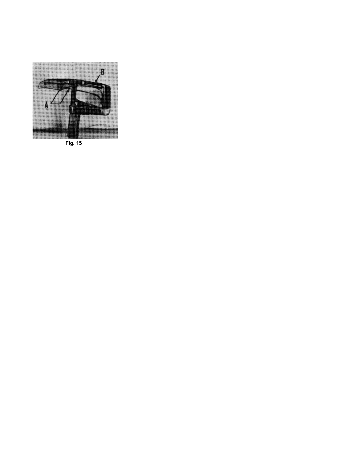
SETTING SPRING RETAINERS ON LOOPER
The spring retainers (A, Fig. 15) on the looper (B) are set correctly when they exert only enough pressure
on the needle thread, around the looper, to retard this thread long enough for the descending needle to
reach a point where the thread released by these retainers cannot fly or be pulled to the left of the needle.
THREAD TENSION RELEASE
The thread tension release is set correctly when it begins to function as
the presser foot is raised to within I/ 8 inch of the end of its travel and
is entirely released when the presser foot reaches its highest position.
On Styles 53100B and C, adjust feed roller lifter connection so that,
when the presser foot and the feed roller are raised, the feed roller does
not contact the presser foot.
SETTING THE ATTACHMENTS
0n Styles 53100B and C, set the folder as close to the presser foot as
possible and still allow free passage of the body and waistband
material. Adjust it laterally so that there is 3/16 inch margin on the under
ply of the canvas to the left of needle. Set the upper folder so that the needle penetration is 1/32 inch from
the top edge of the canvas. Set the body guide so that there is a margin of 1/4 inch to the right of needle.
Adjust the canvas guide to conforrn to the width of the canvas. The folder is adjustable to take waistbands
from 1 3/4 to 4 inches wide. To adapt folder for the extreme narrow width, remove the right hand attaching
screw for the canvas guide and for the extreme wide width, remove the left attaching screw.
Styles 53100D and E are equipped with a swing-out edge guide for abutted edge seaming. The edge guide
should be set down snugly against the stitch tongue in the throat plate. There is an in and out adjustment
screw and lock nut for increasing or decreasing the space between the two abutted edges.
Style 53100E is equipped with an auxiliary pressure plate to produce gathering or ruffling. If set on the
right side of and against the swing-out edge guide, the right ply will be ruffled. If set on the left side of
and against the swing-out edge guide, the left ply will be ruffled. The pressure plate should be set so
that the distance from its edge to the front edge of the throat plate is 19/32 inch.
14
Page 15

EXPLODED VIEWS
AND
DESCRIPTION OF PARTS
FOR
CLASS 53100 ZIG - ZAG MACHINES
15
Page 16

16
Page 17

MAIN FRAME, CAST-OFF PLATE, MISCELLANEOUS COVERS AND PLATES
Ref.
No.
1.
1A.
2.
3.
4.
5.
6.
7.
8.
9.
10.
11.
12.
13.
14.
15.
16.
17.
18.
19.
20.
21.
22.
23.
24.
25.
26.
27.
28.
29.
30.
31.
32.
33.
34.
35.
36.
37.
38.
39.
40.
41.
42.
43.
44.
45.
46.
47.
48.
49.
50.
51.
52.
53.
54.
55.
56.
57.
58.
59.
60.
61.
62.
63.
64.
65.
66.
67.
Part No.
50-216BLK
21657E
22528
22768
87U
52904E
52804E
52904B
22516
52957C
52958D
73A
52904G
57WD
15438C
57WB
43296
605A
98A
20
539
53191
51758
93
53182E
21375BQ
22570A
93
22570A
53182F
53182G
53182A
53137C
22760B
53137D
376
22541B
53182
39582L
52882AC
50-789BLK
22564B
53182N
53182B
53182C
719
22565
53170
53182D
22565
51294R
35731A
51294P
22513
7947
53182K
53182J
53182L
22569B
22848
20
51282AH
53137A
22889A
539
20
22848
53182M
Description
Dowel Pin ......................................................................................................
Washer ..........................................................................................................
Screw ............................................................................................................
Screw ............................................................................................................
Screw ............................................................................................................
Retaining Finger Support Bracket .................................................................
Retaining Finger Support ..............................................................................
Retaining Finger ............................................................................................
Screw ............................................................................................................
Cast-Off Support Plate ..................................................................................
Eyelet ............................................................................................................
Screw ............................................................................................................
Cast-Off Wire ................................................................................................
Nipper Spring Screw, for Styles 53100A, D, E ..................................................
Nipper Spring, for Styles 53100A, D, E .............................................................
Nipper Spring Plate, for Styles 53100A, D, E ....................................................
Thread Nipper Base, for Styles 53100A, D, E ...................................................
Screw, for Styles 53100A, D, E ........................................................................
Screw ............................................................................................................
Washer ..........................................................................................................
Frame Thread Eyelet .....................................................................................
Looper Thread Guard ...................................................................................
Looper Thread Lead-In Eyelet .......................................................................
Screw ............................................................................................................
Cam Gear Fork Frame Support Plate .............................................................
Belt Guard ....................................................................................................
Screw ............................................................................................................
Screw ............................................................................................................
Screw ............................................................................................................
Cover Plate ...................................................................................................
Gasket ..........................................................................................................
Crank Chamber Cover Gasket .....................................................................
Needle Bar Frame Guide Plate, front ............................................................
Screw ............................................................................................................
Needle Bar Frame Guide Plate, rear .............................................................
Screw ............................................................................................................
Screw ............................................................................................................
Crank Chamber Cover .................................................................................
Oil Cap ...................................................................................................
Oil Cap Torsion Spring .............................................................................
Oil Cap Hinge Pin ....................................................................................
Screw ............................................................................................................
Oil Shield .......................................................................................................
Baffle Plate ...................................................................................................
Needle Lever Bearing Oiler ...........................................................................
Screw ............................................................................................................
Screw ............................................................................................................
Take-Up Wire .................................................................................................
Needle Bar Frame Cover ..............................................................................
Screw ............................................................................................................
Screw ............................................................................................................
Presser Bar Connection Guide Plate .............................................................
Oil Tube Clamp .............................................................................................
Screw ............................................................................................................
Nut ................................................................................................................
Gasket ..........................................................................................................
Head Cover ..................................................................................................
Felt Liner .................................................................................................
Screw ............................................................................................................
Screw ............................................................................................................
Washer ..........................................................................................................
Oil Shield, end and back, for Styles 53100A, B, C, D .......................................
Needle Bar Frame Guide Pin .........................................................................
Plug Screw ....................................................................................................
Needle Thread Eyelet ...................................................................................
Washer ..........................................................................................................
Screw ............................................................................................................
End Gasket ...................................................................................................
Amt.
Req.
2
1
1
1
1
1
1
1
1
1
2
3
1
1
1
1
1
1
1
1
1
1
1
2
1
1
10
2
2
1
1
1
1
2
1
1
3
1
1
1
1
2
1
1
1
2
1
1
1
3
1
2
1
3
1
1
1
1
5
3
3
1
2
1
1
1
1
1
17
Page 18

18
Page 19

CLOTH PLATES, CLOTH PLATE COVERS, MISCELLANEOUS AND ATTACHMENTS
Ref.
No.
1.
2.
3.
4.
5.
6.
7.
8.
9.
10.
11.
12.
13.
14.
15.
16.
17.
18.
19.
20.
21.
22.
23.
24.
25.
26.
27.
28.
29.
30.
31.
32.
33.
34.
35.
36.
37.
38.
39.
40.
41.
42.
43.
44.
45.
46.
47.
48.
49.
50.
51.
52.
53.
54.
55.
56.
57.
58.
59.
60.
61.
62.
63.
64.
65.
66.
Part No.
25S
51282AJ
51282AK
52978G
52882AS
52882AE
22548
51480C
51301D
22760A
35772H
51281AC
22845B
51281AJ-219
51281T-219
25C
29480BZ
39531AR
77A
39531B
604
39531C
53132B
53132A
22561
53132
23425V
22514
GR-23450L
188D
8372A
23450U
23450M
23450P
23450R
90
23450V
23450N
23450T
23450S
53102
22760A
50368E
25C
23450W
53101
80
22845B
88D
25S
23437G
22839C
22585A
22524
53782B
51382B
52982E
52982D
22848
41394A
22733B
222D
87
87
22839
51280AA
Description
Screw ............................................................................................................
Oil Shield, front, for Styles 53100A, C, D, E ......................................................
Spring .....................................................................................................
Hinge Pin .................................................................................................
Gasket, for Styles 53100A, D, E ......................................................................
Crank Chamber Cover, for Styles 53100A, D, E ..............................................
Screw, for Styles 53100A, D, E ........................................................................
Throat Plate Support, for Style 53100E ...........................................................
Cloth Plate, for Styles 53100A, D, E ................................................................
Screw, for Styles 53100A, D, E ........................................................................
Washer, for Styles 53100A, D, E ......................................................................
Cloth Plate Cover Spring, for Styles 53100A, D, E ...........................................
Pivot Screw, for Styles 53100A, D, E ................................................................
Cloth Plate Cover, for Style 53100E ...............................................................
Cloth Plate Cover, for Styles 53100A, D .........................................................
Screw, for Style 53100E ..................................................................................
Auxiliary Presser Plate Assembly, for Style 53100E ..........................................
Operating Lever .....................................................................................
Screw ...............................................................................................
Shaft Collar .............................................................................................
Screw ...............................................................................................
Spring .....................................................................................................
Auxiliary Pressure plate Bracket ..............................................................
Pressure Plate Shaft ................................................................................
Screw .....................................................................................................
Auxiliary Pressure Plate ...........................................................................
Washer Plate .................................................................................................
Screw, for Style 53100B ..................................................................................
Waistband Folder, complete, for Style 53100B ..............................................
Screw .....................................................................................................
Washer ...................................................................................................
Lower Scroll, adjustable .........................................................................
Folder Base .............................................................................................
Adjustable Waistband Guide, lower .......................................................
Adjustable Support, for waistband guide, lower ....................................
Screw .....................................................................................................
Adjusting Screw ......................................................................................
Adjustable Waistband Guide, upper ......................................................
Top Scroll Support, adjustable ................................................................
Top Scroll ................................................................................................
Cloth Plate Cover, for Styles 53100B, C ..........................................................
Screw ............................................................................................................
Washer ..........................................................................................................
Screw ............................................................................................................
Edge Guide, for Style 53100B ........................................................................
Cloth Plate, for Styles 53100B, C ....................................................................
Screw ............................................................................................................
Screw ............................................................................................................
Screw ............................................................................................................
Screw ............................................................................................................
Folder Support Bracket, for Style 53100B .......................................................
Screw ............................................................................................................
Screw ............................................................................................................
Screw ............................................................................................................
Oil Reservoir Top Cover .................................................................................
Gasket ..........................................................................................................
Gasket ..........................................................................................................
Oil Reservoir Back Cover ...............................................................................
Screw ............................................................................................................
Gasket ..........................................................................................................
Screw ............................................................................................................
Throat Plate (See Page 37) ............................................................................
Screw, for Styles 53100B, C ............................................................................
Screw, for Styles 53100B, C ............................................................................
Screw, for Styles 53100A, D, E ........................................................................
Screw ............................................................................................................
Throat Plate Support, for Styles 53100A, B, C, D .............................................
Amt.
Req.
2
1
2
1
1
1
4
1
1
3
3
1
1
1
1
2
1
1
1
1
1
1
1
1
2
1
1
2
1
5
5
1
1
1
1
4
1
1
1
1
1
2
2
2
1
1
3
1
2
1
1
2
2
7
1
1
1
1
9
2
1
1
1
1
2
3
1
19
Page 20

20
Page 21

MAIN FRAME, BUSHINGS AND MISCELLANEOUS OILING PARTS
Ref.
No.
1.
2.
3.
4.
5.
6.
7.
8.
9.
10.
11.
12.
13.
14.
15.
16.
17.
18.
19.
20.
21.
22.
23.
24.
25.
26.
27.
28.
29.
30.
31.
32.
33.
34.
35.
36.
37.
38.
39.
40.
41.
42.
43.
44.
45.
46.
47.
48.
49.
50.
51.
52.
53.
54.
55.
56.
57.
Part No.
GR-53193
643-127BLK
52393H
22569B
22823A
51295A
22823B
51493AY
51493BG
51493BH
51493BJ
22560B
52894AK
51493BK
52942W
52944U
52890C
51290T
52942X
52794G
52894AB
52894AB
90
90
52936
22597
52944T
660-136
258A
51257AA
666-210
51294V
666-214
52894AD
52894AE
22729AB
51294Z
21212
666-201
666-209
GR-51294S
22729B
51294K
52883R
21657X
52891B
50-648BLK
52942Y
22889C
22889D
666-114
35178D
22571A
666-65
666-118
666-111
666-179
22539H
56390E
Description
Oil Pump Assembly .......................................................................................
Gasket ..........................................................................................................
Oil Pump Intake Housing ...............................................................................
Screw ...........................................................................................................
Screw ...........................................................................................................
Mounting Isolator .........................................................................................
Screw ...........................................................................................................
Oil Pan Base Plate .........................................................................................
Base Plate Felt Pad .......................................................................................
Filter Cap Assembly ......................................................................................
Washer, sponge rubber .........................................................................
Screw ...........................................................................................................
Oil Tube, for looper rocker and left ball joint .................................................
Lint Filter Screen ...........................................................................................
Looper Drive Lever Shaft Bushing, front ........................................................
Looper Rock Shaft Bushing, right ..................................................................
Main Shaft Bushing, left and inner right .........................................................
Main Shaft Bushing, middle ..........................................................................
Looper Drive Lever Shaft Bushing, rear .........................................................
Oil Tube, for feed lift and looper avoid eccentric .........................................
Oil Tube Holder, for Styles 53100A, B, C, D .....................................................
Oil Tube Holder, for Style 53100E ...................................................................
Screw, for Styles 53100A, B, C, D ...................................................................
Screw, for Style 53100E .................................................................................
Feed Rocker Shaft Bushing ...........................................................................
Screw, for Style 53100E .................................................................................
Looper Rocker Shaft Bushing, left .................................................................
Oil Tube, for feed crank link ..........................................................................
Nut .........................................................................................................
Lower Presser Bar Bushing .............................................................................
Oil Attraction Felt .........................................................................................
Oil Siphon Tube .............................................................................................
Felt Lint Filter ...........................................................................................
Oil Tube, for differential feed bar shaft, for Style 53100E ...............................
Oil Tube, for differential feed bar guide, for Style 53100E .............................
Screw ...........................................................................................................
Oil Tube Connection ....................................................................................
Oil Siphon Connection Locking Ring ......................................................
Felt Plug ........................................................................................................
Felt Plug ........................................................................................................
Oil Siphon Assembly .....................................................................................
Screw .....................................................................................................
Upper Clamp .........................................................................................
Presser Foot Lifter Lever Bushing ...................................................................
Tension Release Lever Shaft Bushing ............................................................
Main Shaft Housing, including bushing .........................................................
Lucite Oil Gauge ..........................................................................................
Looper Rocker Shaft Synchronizing Stud ......................................................
Adapter Plug Screw .....................................................................................
Adapter Plug Screw .....................................................................................
Oil Wick ........................................................................................................
Spring ...........................................................................................................
Plug Screw ....................................................................................................
Oil Wick ........................................................................................................
Oil Wick ........................................................................................................
Oil Wick ........................................................................................................
Wedge Pin ....................................................................................................
Plug Screw ....................................................................................................
Crankshaft Bearing Housing Gasket .............................................................
Amt.
Req.
1
1
1
3
2
4
1
1
1
1
1
1
1
1
1
1
2
1
1
1
1
3
1
3
2
2
1
1
1
1
1
1
1
1
1
1
1
1
1
1
1
1
1
1
1
1
1
1
2
1
2
4
15
2
2
2
2
1
1
21
Page 22

22
Page 23

FOR STYLES 53100B AND C ONLY
CLUTCH ASSEMBLY, CLUTCH DRIVE SHAFT GEAR AND HOUSING ASSEMBLY
Ref.
No.
1.
2.
3.
4.
5.
6.
7.
8.
9.
10.
11.
12.
12A.
13.
14.
15.
16.
17.
18.
19.
20.
21.
22.
23.
24.
25.
26.
27.
28.
29.
30.
31.
32.
33.
34.
35.
36.
37.
38.
39.
40.
41.
42.
43.
44.
Part No.
29476JD
53139H
22729C
18
41331G
51236F
269
53139K
660-169
269
20
29476JF
53139B
51236G
51236B
22768
82
53139
53139A
269
53139E
53139D
22888A
53139F
53139C
98
39153G
12982
22791D
41394A
22733B
22861B
22548
258
53139Z
53139AC
22561
22768
40-107
53139AB
53139AD
53139AE
53139AH
51239AA
51239AB
22747B
43443Q
Description
Clutch Drive Connecting Rod Assembly ......................................................
Clutch Drive Ball Joint ............................................................................
Screw ...............................................................................................
Nut .........................................................................................................
Connecting Rod ....................................................................................
Ferrule ....................................................................................................
Nut .........................................................................................................
Crank Strap ............................................................................................
Needle Bearing ......................................................................................
Nut ...............................................................................................................
Washer .........................................................................................................
Clutch Drive Shaft Gear and Housing Assembly ...........................................
Clutch Drive Shaft ..................................................................................
Feed Crank Stud ....................................................................................
Feed Crank Stud Cap .............................................................................
Screw .....................................................................................................
Screw .....................................................................................................
Clutch Drive Shaft Gear .........................................................................
Bushing ............................................................................................
Nut .........................................................................................................
Idler Gear Eccentric Bushing .................................................................
Idler Gear ...............................................................................................
Screw .....................................................................................................
Idler Gear Bracket ..................................................................................
Clutch Drive Shaft Gear .........................................................................
Screw ...............................................................................................
Nut .........................................................................................................
Nut .........................................................................................................
Pin ..........................................................................................................
Gasket ...................................................................................................
Screw .....................................................................................................
Screw ...........................................................................................................
Screw ...........................................................................................................
Nut ...............................................................................................................
Roller Feed Shaft Guard ...............................................................................
Feed Roller Stripper ......................................................................................
Screw ...........................................................................................................
Screw ...........................................................................................................
Washer .........................................................................................................
Feed Roller Lifter ...........................................................................................
Feed Roller, fine knurl ...................................................................................
Feed Roller, fifty teeth ..................................................................................
Feed Roller, coarse knurl ..............................................................................
Feed Roller Block ..........................................................................................
Bushing ..................................................................................................
Screw .....................................................................................................
Nut .........................................................................................................
Amt.
Req.
1
1
2
1
1
1
1
1
1
1
1
1
1
1
1
2
1
1
1
1
1
1
1
1
1
2
2
1
1
1
1
4
3
1
1
1
1
1
1
1
1
1
1
1
1
1
1
45. thru 90. See Following page
23
Page 24

24
Page 25

FOR STYLES 53100B AND C ONLY
CLUTCH ASSEMBLY, CLUTCH DRIVE SHAFT GEAR AND HOUSING ASSEMBLY
Ref.
No.
Part No.
1. thru 44. See Previous page
45.
53139AA
46.
50-799BLK
47.
88
22874
48.
12987A
49.
53139AG
50.
51239G
51.
22894T
52.
61339F
53.
660-239
54.
22580
55.
56.
57.
58.
59.
60.
61.
62.
63.
64.
65.
66.
67.
68.
69.
70.
73.
74.
75.
76.
77.
78.
79.
80.
81.
82.
83.
84.
85.
86.
87.
88.
89.
90.
6042A
29476JE
53139Y
460
88
53139W
22892C
53139L
53139N
53139P
53139M
11638M
54278Y
54278W
54274P
54274N
719
61351C
22894H
53139X
22651CB4
605
53139R
54274H
54274L
29480KP
54274J
54274H
53139S
53139V
53139U
538
53139T
22593
52882AS
55A.
67A.
Description
Roller Feed Mounting Bracket ......................................................................
Nut ...............................................................................................................
Plunger Spring ..............................................................................................
Universal Joint ..............................................................................................
Roller Feed Shaft ..........................................................................................
Universal Joint ..............................................................................................
Washer .........................................................................................................
Clutch Assembly ..........................................................................................
Gasket .........................................................................................................
Guide ....................................................................................................
Screw .....................................................................................................
Screw .....................................................................................................
Set Screw ...............................................................................................
Set Screw ...............................................................................................
Roller Feed Driving Gear Shaft ...............................................................
Collar .....................................................................................................
Screw ..............................................................................................
Clutch Shaft ...........................................................................................
Stop Screw .............................................................................................
Clutch Housing ......................................................................................
Bushing ............................................................................................
Bushing ............................................................................................
Bushing ............................................................................................
Nut .........................................................................................................
Driving Washer .......................................................................................
Sleeve ....................................................................................................
Washer ..................................................................................................
Tension Spring ........................................................................................
Set Screw ...............................................................................................
Washer ..................................................................................................
Spot Screw .............................................................................................
Roller Feed Gear ....................................................................................
Set Screw .........................................................................................
Screw .....................................................................................................
Drive Lever .............................................................................................
Clutch Disc ............................................................................................
Clutch Roller ..........................................................................................
Clutch Spring and Pin .............................................................................
Support Plate .........................................................................................
Clutch Disc ............................................................................................
Clutch Barrel Assembly ..........................................................................
Core ................................................................................................
Barrel ...............................................................................................
Screw ..............................................................................................
Clutch Barrel Gear ..........................................................................
Screw ..............................................................................................
Amt.
Req.
1
1
1
1
2
1
1
2
1
1
2
1
1
1
1
1
1
1
1
1
2
1
2
1
1
1
1
1
1
1
1
2
6
1
1
6
12
1
1
1
1
1
3
1
3
1
25
Page 26

26
Page 27

CRANKSHAFT, NEEDLE LEVER AND LOOPER DRIVING PARTS
Ref.
No.
1.
2.
3.
4.
5.
6.
7.
8.
9.
10.
11.
12.
13.
14.
15.
16.
17.
18.
19.
20.
21.
22.
23.
24.
25.
26.
27.
28.
29.
30.
31.
32.
33.
34.
35.
36.
37.
38.
39.
40.
Part No.
54484U
22564D
52943L
22894X
56343D
22894X
52942AA
52951C
29476LE
22729D
51243C
22729D
22587
29476HL
51216M
53138L
22894X
29476JZ
53138E
53138F
53138J
22733
12934A
53138C
50-744BLK
21657E
18
53138D-0420
53138D-0425
53138D-0430
22874F
53137E
53137J
18
22841H
269
53137H
18
53137F
52891B
22569B
660-202
Description
Oil Distributor ................................................................................................
Screw .....................................................................................................
Collar ...........................................................................................................
Screw .....................................................................................................
Collar ...........................................................................................................
Screw .....................................................................................................
Looper Drive Lever Rocker Shaft ..................................................................
Washer .........................................................................................................
Looper Driving Lever Crank Assembly ..........................................................
Screw, lower ..........................................................................................
Ball Stud Guide .......................................................................................
Screw .....................................................................................................
Screw, upper .........................................................................................
Crankshaft Assembly, .910 inch throw ..........................................................
Needle Bearing ......................................................................................
Cam Driving Gear ........................................................................................
Screw .....................................................................................................
Cam Gear, Cam Gear Fork and Needle Bar Frame Connecting Rod Assembly..
Cam Gear Fork Frame ............................................................................
Cam Gear Fork Shaft ..............................................................................
Cam Gear ..............................................................................................
Screw .....................................................................................................
Nut .........................................................................................................
Cam Gear Fork and Adjusting Segment .................................................
Pin ....................................................................................................
Washer ...................................................................................................
Nut .........................................................................................................
Cam Gear Fork Wear Plate, .042 inch thick ............................................
Cam Gear Fork Wear Plate, .0425 inch thick ..........................................
Cam Gear Fork Wear Plate, .043 inch thick ............................................
Screw .....................................................................................................
Needle Bar Frame Connecting Rod Assembly .......................................
Ball Joint, lower ................................................................................
Nut ...................................................................................................
Adjusting Screw ...............................................................................
Nut ...................................................................................................
Connecting Rod ..............................................................................
Nut ...................................................................................................
Ball Joint, upper .....................................................................................
Crankshaft Bushing Housing, including bushing ...........................................
Screw ...........................................................................................................
"O" Ring, for pulley ........................................................................................
Amt.
Req.
1
1
1
4
1
4
1
1
1
2
1
1
2
1
28
1
2
1
1
2
1
2
3
1
2
1
1
2
2
2
1
1
1
2
1
1
1
1
1
1
3
1
41. thru 77. See Following page
27
Page 28

28
Page 29

CRANKSHAFT, NEEDLE LEVER AND LOOPER DRIVING PARTS
Ref.
No.
Part No.
1. thru 40. See Previous page
41.
52921B
42.
22894G
43.
51216P
44.
51216N
45.
29066R
46.
22559G
47.
53137
48.
22894T
49.
29348AX
50.
52336A
51.
660-215
52.
56354D
53.
78
54.
53154
55.
88A
56.
77
57.
53115A
58.
51250B
59.
56350A
60.
51150
61.
660-212
62.
51250D
63.
51250F
64.
22586R
65.
22768
66.
56358
67.
27-435BLK
68.
53117A
69.
56
70.
53137M
71.
56358A
72.
22768
660-212
73.
51216G
74.
15444F
75.
54484U
76.
22564D
77.
Description
Pulley ...........................................................................................................
Screw .....................................................................................................
Nut ...............................................................................................................
Washer .........................................................................................................
Needle Lever Connecting Rod and Upper Bearing Assembly ......................
Screw .....................................................................................................
Needle Bar Frame ........................................................................................
Screw .....................................................................................................
Needle Lever Assembly ...............................................................................
Feed Crank Pin ......................................................................................
Retaining Ring .......................................................................................
Needle Bar Link ......................................................................................
Screw .....................................................................................................
Needle Bar Connection .........................................................................
Screw .....................................................................................................
Needle Lever .........................................................................................
Needle Lever Stud .................................................................................
Needle Lever Shaft Stop Collar ....................................................................
Oil Seal Ring .................................................................................................
Washer .........................................................................................................
Gasket .........................................................................................................
Screw ...........................................................................................................
Screw ...........................................................................................................
Needle Bar Thread Eyelet .............................................................................
Needle Bar Thread Washer ..........................................................................
Needle Bar ...................................................................................................
Needle Clamp Nut .......................................................................................
Needle Bar Frame Pivot Pin ..........................................................................
Needle Lever Thread Eyelet .........................................................................
Screw ...........................................................................................................
Oil Seal Ring .................................................................................................
Needle Lever Connecting Rod ....................................................................
Washer, redwood ........................................................................................
Oil Distributor ................................................................................................
Screw .....................................................................................................
Screw ..............................................................................................
Bushing ............................................................................................
Amt.
Req.
1
2
1
1
1
2
1
2
1
2
1
1
1
1
2
1
1
1
1
1
1
1
1
1
1
1
1
1
1
1
1
1
2
2
1
1
1
29
Page 30

30
Page 31

LOOPER ROCKER AND CONNECTING ROD PARTS
Ref.
No.
1.
2.
3.
4.
5.
6.
7.
8.
9.
10.
11.
12.
13.
14.
15.
16.
17.
18.
19.
20.
21.
22.
23.
24.
25.
26.
27.
28.
29.
30.
31.
32.
33.
34.
35.
36.
37.
38.
Part No.
51244B
22519H
18
51216N
51244L
51244N
55244G
22768
51144
53108C
53108B
1740
22738B
53111A
53111
98
51244
51246
96
18
29192
51745
51213
15465F
22894W
258A
22829
73
55241N
269
39141
18
52942P
22882A
20
52942AE
52941D
18B
Description
Looper Rocker Shaft Arm ..............................................................................
Screw .....................................................................................................
Nut ...............................................................................................................
Washer .........................................................................................................
Thrust Washer ...............................................................................................
Looper Rocker Frame Clamp Collar .............................................................
Looper Rocker Shaft Collar Stud ...................................................................
Screw ...........................................................................................................
Looper Rocker Shaft .....................................................................................
Looper Assembly ..........................................................................................
Looper ...................................................................................................
Pin ....................................................................................................
Screw .....................................................................................................
Looper Retainer, front ............................................................................
Looper Retainer, bottom .......................................................................
Screw ...........................................................................................................
Looper Rocker Frame ...................................................................................
Looper Rocker Stud Nut ................................................................................
Screw ...........................................................................................................
Nut ...............................................................................................................
Looper Rocker Assembly ..............................................................................
Looper Rocker Cone Stud ......................................................................
Looper Rocker .......................................................................................
Looper Rocker Cone ..............................................................................
Allen Screw......................................................................................
Nut .........................................................................................................
Screw .....................................................................................................
Screw ...........................................................................................................
Looper Connecting Rod Ball Joint, left .........................................................
Nut ...............................................................................................................
Looper Connecting Rod ..............................................................................
Nut ...............................................................................................................
Looper Drive Lever .......................................................................................
Screw .....................................................................................................
Washer ...................................................................................................
Looper Lever Stud Bolt ..................................................................................
Looper Connecting Rod Ball Joint, right .......................................................
Nut Plate .......................................................................................................
Amt.
Req.
1
1
1
1
2
1
1
1
1
1
1
1
2
1
1
1
1
1
1
1
1
1
1
1
2
1
1
1
1
1
1
1
1
1
1
1
1
1
.
31
Page 32

32
Page 33

MAIN SHAFT AND FEED MECHANISM
Ref.
No.
1.
2.
3.
4.
5.
6.
7.
8.
9.
10.
11.
12.
13.
14.
15.
16.
17.
18.
19.
20.
21.
22.
23.
24.
25.
26.
27.
28.
29.
30.
31.
32.
33.
34.
35.
36.
37.
38.
39.
40.
41.
42.
43.
44.
45.
46.
47.
48.
49.
50.
51.
52.
53.
Part No.
51054
666-149
269
20
51236E
660-169
51236D
51236F
51236G
51236B
22768
82
52922C
22801
51236A
29476DR
51145A
51142C
22894D
29476DX
51306
22894D
51145A
51236A
52923D
22580D
51134
22560B
538
56334E
51134J
258A
22863
77
22834
53125
22801
22528
51225W
22585B
77
51235A
51235G
22519C
482
98
51235
98
51134C
51134R
51134P
8
Description
Link Pin .........................................................................................................
Oil Wick .................................................................................................
Nut ...............................................................................................................
Washer ........................................................................................................
Feed Crank Link Assembly ...........................................................................
Needle Bearing .....................................................................................
Feed Crank Link .....................................................................................
Feed Crank Link Ferrule .........................................................................
Feed Crank Stud ..........................................................................................
Feed Crank Stud Cap ..................................................................................
Screw ...........................................................................................................
Screw ...........................................................................................................
Main Shaft, for Styles 53100A, B, C, D ............................................................
Screw ...........................................................................................................
Link Pin .........................................................................................................
Feed Lift Eccentric Assembly, for Styles 53100A, B, C, D ...............................
Eccentric Bearing .................................................................................
Eccentric, .080 inch throw .....................................................................
Screw ..............................................................................................
Looper Avoid Eccentric Assembly ...............................................................
Eccentric, .072 inch throw .....................................................................
Screw ..............................................................................................
Eccentric Bearing .................................................................................
Link Pin .........................................................................................................
Take-up .......................................................................................................
Screw ....................................................................................................
Feed Bar, for Styles 53100A, B, C, D ...............................................................
Screw ....................................................................................................
Feed Dog Height Adjusting Screw .........................................................
Feed Dog Holder ...................................................................................
Feed Dog Holder Washer ......................................................................
Nut .........................................................................................................
Feed Dog Holder Adjusting Screw .........................................................
Screw ...........................................................................................................
Needle Guard Adjusting Screw, for Styles 53100A, B, C, D ...........................
Feed Dog (See Page 41) ..............................................................................
Needle Guard, for Styles 53100A, B, C, D ......................................................
Stud Screw ............................................................................................
Screw, for feed dog on Styles 53100A, B, C, D ..............................................
Washer, for needle guard on Styles 53100A, B, C, D .....................................
Screw, for needle guard on Styles 53100A, B, C, D .......................................
Screw ...........................................................................................................
Feed Rocker Arm, for Styles 53100A, B, C, D .................................................
Washer ..................................................................................................
Screw ....................................................................................................
Collar ...........................................................................................................
Screw ....................................................................................................
Feed Rocker, for Styles 53100A, B, C, D ........................................................
Screw ....................................................................................................
Feed Bar Shaft .............................................................................................
Lubricating Felt Guard, for Styles 53100A, B, C, D .........................................
Lubricating Felt, for Styles 53100A, B, C, D ....................................................
Feed Rocker Shaft .......................................................................................
Amt.
Req.
1
1
1
1
1
1
1
1
1
1
2
1
1
1
1
1
1
1
1
1
1
1
1
1
1
2
1
1
1
1
1
1
1
1
1
1
1
1
1
1
1
1
1
2
2
2
1
1
2
1
1
1
1
33
Page 34

34
Page 35

FOR STYLE 53100E ONLY
MAIN SHAFT AND FEED MECHANISM
Ref.
No.
1.
2.
3.
4.
5.
6.
7.
8.
9.
10.
11.
12.
13.
14.
15.
16.
17.
18.
19.
20.
21.
22.
23.
24.
25.
26.
27.
28.
29.
30.
31.
32.
33.
34.
35.
36.
37.
38.
39.
40.
41.
42.
43.
44.
45.
46.
47.
47A.
48.
49.
50.
51.
52.
53.
54.
55.
56.
57.
58.
59.
60.
61.
Part No.
82
52822B
22801
29476DV
51406
22894D
51145A
90
3026A
52834H
CL21
52853
52925D
53125A
22519J
51235G
22593
52805D16
22593
39237D
52834
22560B
39237G
22747
77
39237
22565C
907
52835V
CL21
51225W
52835S
22868A
52835Q
22758B
51435
12934A
52835G
52835U
719
52835
43139A
52835N
22848
25CC
8372A
9937
20
51435B
52835K
61267G
77
52836C
51235G
22519C
22516
52836H
57836F
52836
89
51134C
Description
Screw ...........................................................................................................
Main Shaft ....................................................................................................
Screw ...........................................................................................................
Feed Lift Eccentric Assembly ........................................................................
Feed Lift Eccentric, .062 inch throw .......................................................
Screw .....................................................................................................
Eccentric Bearing ..................................................................................
Screw ...........................................................................................................
Differential Feed Dog (Also See Page 41) .....................................................
Differential Feed Bar ....................................................................................
Oil Wick ..................................................................................................
Main Feed Dog Holder .................................................................................
Needle Guard Holder ...................................................................................
Needle Guard ..............................................................................................
Screw ...........................................................................................................
Washer .........................................................................................................
Screw ...........................................................................................................
Main Feed Dog (Also See Page 41) ...............................................................
Screw ...........................................................................................................
Differential Feed Bar Guide Plate .................................................................
Main Feed Bar ..............................................................................................
Screw .....................................................................................................
Bushing ..................................................................................................
Feed Dog Height Adjusting Screw ..........................................................
Screw ...........................................................................................................
Differential Feed Bar Guide ..........................................................................
Screw .....................................................................................................
Nut ...............................................................................................................
Differential Feed Bar Driving Link ..................................................................
Oil Wick ..................................................................................................
Washer .........................................................................................................
Differential Feed Fork Block ..........................................................................
Screw ...........................................................................................................
Differential Feed Fork ...................................................................................
Screw ...........................................................................................................
Differential Feed Control Lever, rear ............................................................
Nut ...............................................................................................................
Control Lever Link .........................................................................................
Pivot Stud Insert ............................................................................................
Screw ...........................................................................................................
Differential Feed Control Lever ....................................................................
Indicator Stop ..............................................................................................
Control Lever Stop Plate ...............................................................................
Screw ...........................................................................................................
Screw ...........................................................................................................
Indicator Stop Washer ..................................................................................
Nut ...............................................................................................................
Washer .........................................................................................................
Differential Feed Control Lever Bushing .......................................................
Control Lever Spring .....................................................................................
Lifter Lever Spring Pin ....................................................................................
Screw ...........................................................................................................
Feed Rocker Arm ..........................................................................................
Washer ...................................................................................................
Screw .....................................................................................................
Screw ...........................................................................................................
Feed Rocker Segment Plate .........................................................................
Differential Feed Bar Driving Link Slide Block ................................................
Feed Rocker .................................................................................................
Screw .....................................................................................................
Feed Bar Shaft ..............................................................................................
Wool Yarn .....................................................................................................
Amt.
Req.
1
1
1
1
1
1
1
1
1
1
1
1
1
1
1
1
2
1
4
2
1
1
2
1
1
1
2
1
1
1
2
1
1
1
3
1
2
1
1
1
1
2
1
2
2
2
2
1
1
1
1
1
1
2
2
3
1
1
1
2
1
1
35
Page 36

36
Page 37

THREAD TENSION AND FOOT LIFTER LEVER PARTS
Ref.
No.
1.
2.
3.
4.
5.
6.
7.
8.
9.
10.
11.
12.
13.
14.
15.
16.
17.
18.
19.
20.
21.
22.
23.
24.
25.
25A.
26.
26A.
27.
28.
29.
30.
31.
32.
33.
34.
35.
36.
37.
Part No.
43266
51491C
51292D
668-25
668-28
51292A
51292G
109
51292F8
51292F2
51292C
22598C
21657-3
80557
52892
21657W
21657Y
22596
402
258
35780B
51283H
56356
51256C
53157
51257K
53183A
53783A
22596F
51257M
402
22557B
52883S
22758C
53783L
53783M
660-207
53783N
22537
Description
Nut ...............................................................................................................
Lead-in Thread Eyelet ..................................................................................
Tension Thread Eyelet ...................................................................................
Eyelet .....................................................................................................
Eyelet Locking Ring ................................................................................
Tension Post Ferrule ......................................................................................
Tension Post ..................................................................................................
Tension Disc ..................................................................................................
Tension Spring (needle) ................................................................................
Tension Spring (looper) .................................................................................
Tension Nut ...................................................................................................
Tension Release Stud ....................................................................................
Tension Disc Separator .................................................................................
Washer .........................................................................................................
Tension Post Support ....................................................................................
Tension Release Lever Shaft .........................................................................
Tension Release Lever Connection ..............................................................
Screw .....................................................................................................
Screw .....................................................................................................
Nut, for Styles 53100B, C ................................................................................
Lifter Lever Extension, for Styles 53100B, C ....................................................
Presser Foot Lifter Lever ................................................................................
Presser Spring Regulator ...............................................................................
Presser Bar Spring .........................................................................................
Presser Bar, for Styles 53100B, C ....................................................................
Presser Bar, for Styles 53100A, D, E .................................................................
Presser Foot Lifter Lever Link, for Styles 53100B, C ..........................................
Presser Foot Lifter Lever Link, for Styles 53100A, D, E ......................................
Screw ...........................................................................................................
Presser Bar Connection and Guide ..............................................................
Screw ...........................................................................................................
Screw ...........................................................................................................
Presser Foot Lifter Lever Bell Crank Spring .....................................................
Screw ...........................................................................................................
Presser Foot Lifter Lever Bell Crank ...............................................................
Presser Foot Lifter Lever Connecting Rod .....................................................
Oil Seal Ring ..................................................................................................
Presser Foot Lifter Lever, internal ..................................................................
Screw .....................................................................................................
Amt.
Req.
1
2
2
2
2
2
2
4
1
1
2
1
1
2
1
1
1
1
1
2
1
1
1
1
1
1
1
1
1
1
1
1
1
1
1
1
1
1
1
37
Page 38

38
Page 39

FEED DOGS, THROAT PLATES AND PRESSER FEET
Ref.
No.
1.
2.
3.
4.
5.
6.
7.
8.
9.
10.
11.
12.
13.
14.
15.
16.
17.
18.
19.
20.
21.
22.
23.
24.
25.
26.
27.
28.
29.
30.
31.
32.
33.
34.
35.
36.
37.
38.
39.
40.
41.
42.
43.
44.
45.
46.
Part No.
3026A
52805D16
53124C
53131C
187B
53120D
51230U
22570A
61130D
61130E
6990
22799U
22799N
61130F
23441F
23441H
22596
22738D
60078Z
41071G
35772H
23441G
22585
53105A
53124A
53131C
187B
53120B
53130A
91
22799B
53130E
53105B
53124B
53130C
22894W
53139AF
28
22798A
53130B
53130D
53120C
53130A
91
22799B
53130F
Description
Differential Feed Dog, for Style 53100E .........................................................
Main Feed Dog, for Style 53100E ...................................................................
Throat Plate, for Style 53100E ........................................................................
Stitch Tongue .........................................................................................
Screw .....................................................................................................
Presser Foot, for Style 53100E ........................................................................
Presser Foot Shank ..................................................................................
Screw .....................................................................................................
Presser Foot Plunger, right ......................................................................
Presser Foot Plunger, left ........................................................................
Spring .....................................................................................................
Hinge Screw ...........................................................................................
Screw .....................................................................................................
Equalizer ................................................................................................
Edge Guide Assembly, for Styles 53100D, E ...................................................
Edge Guide Bracket ...............................................................................
Screw .....................................................................................................
Screw .....................................................................................................
Nut .........................................................................................................
Nut .........................................................................................................
Spring Washer ........................................................................................
Edge Guide ............................................................................................
Screw .....................................................................................................
Feed Dog, for Styles 53100A, D .....................................................................
Throat Plate, for Styles 53100A, D ..................................................................
Stitch Tongue .........................................................................................
Screw .....................................................................................................
Presser Foot, for Style 53100D ........................................................................
Presser Foot Shank ..................................................................................
Screw ...............................................................................................
Hinge Screw ...........................................................................................
Presser Foot Bottom ................................................................................
Feed Dog, for Styles 53100B, C ......................................................................
Throat Plate, for Styles 53100B, C ..................................................................
Presser Foot Shank, for Styles 53100B, C ........................................................
Screw .....................................................................................................
Cloth Guard, for Styles 53100B, C ..................................................................
Screw ...........................................................................................................
Screw ...........................................................................................................
Presser Foot Bottom, for Styles 53100B, C ......................................................
Presser Foot Hinge Pin Stud, for Styles 53100B, C ...........................................
Presser Foot, for Style 53100A ........................................................................
Presser Foot Shank ..................................................................................
Screw ...............................................................................................
Hinge Screw ...........................................................................................
Presser Foot Bottom ................................................................................
Amt.
Req.
1
1
1
1
1
1
1
1
1
1
2
2
1
1
1
1
1
1
1
1
1
1
1
1
1
1
1
1
1
1
1
1
1
1
1
1
1
1
1
1
1
1
1
1
1
1
39
Page 40

40
Page 41

THREAD STAND, KNEE PRESS AND TAPE REEL PARTS
Ref.
No.
1.
2.
3.
4.
5.
6.
7.
8.
9.
10.
11.
12.
13.
14.
15.
16.
17.
18.
19.
20.
21.
22.
23.
24.
25.
26.
27.
28.
29.
30.
31.
32.
33.
34.
35.
36.
37.
38.
39.
40.
41.
42.
43.
Part No.
21101W
51493BC
21660H
660-168
21664
69FD
660-219G
21664F
92201
12982
80
21662V
22650CE6
21662R
39536AD
21662U
43137E
22557A
21662T
21662S
531
21664C
SC303
21663A
21217A
22650CB4
22651CD4
93A
753
21178A
21177A
22647K24
1349A5
752
21104B20
421D28
421D38
21388AU
116
21388
12288403
21114AV
22651CD4
28604
Description
Thread Stand, complete ..............................................................................
Lifter Link ......................................................................................................
Knee Press Assembly, for Styles 53100A, D, E .................................................
Knee Press Plate Cushion .......................................................................
Knee Press Plate .....................................................................................
Screw ..............................................................................................
Roll Pin ...................................................................................................
Mounting Bracket ..................................................................................
Screw .....................................................................................................
Nut .........................................................................................................
Screw .....................................................................................................
Torsion Spring .........................................................................................
Screw .....................................................................................................
Knee Press Lifter Arm ..............................................................................
Spring Washer ........................................................................................
Knee Press Lever ....................................................................................
Washer ..................................................................................................
Screw .....................................................................................................
Knee Press Link .......................................................................................
Knee Press Link Connection ...................................................................
Screw .....................................................................................................
Bracket ..................................................................................................
Wood Screw (#12 x 1 inch) .....................................................................
Knee Press Plate Lever ...........................................................................
Tape Reel Axle Support, for Styles 53100B, C ................................................
Screw .....................................................................................................
Screw .....................................................................................................
Screw, for Styles 53100B, C ...........................................................................
Tape Reel Disc Collar, for Styles 53100B, C ....................................................
Tape Reel Disc, for Styles 53100B, C ..............................................................
Tape Reel Spring Collar, for Styles 53100B, C ................................................
Thumb Screw .........................................................................................
Tension Spring ........................................................................................
Tape Reel Axle, for Styles 53100B, C ..............................................................
Tape Reel Rod, 20 inches long, for Styles 53100B, C ......................................
Treadle Chain, 28 inches long, for presser foot on Styles 53100B, C ...........
Treadle Chain, 38 inches long, for differential feed on Style 53100E .........
Wrench, for 3/8 inch hexagonal nut .............................................................
Wrench, for 9/32 inch nut .............................................................................
Wrench, single end, for 3/8 inch nut .............................................................
Thread Tweezer ............................................................................................
Tape Reel Base, for Styles 53100B, C .............................................................
Screw .....................................................................................................
Oil (1 Pint) .....................................................................................................
Amt.
Req.
1
1
1
1
1
1
1
1
1
1
2
1
1
1
2
1
1
1
1
1
1
1
2
1
1
1
1
1
1
2
1
1
1
1
1
1
1
1
1
1
1
1
2
1
41
Page 42

NUMERICAL INDEX OF PARTS
Part No. Page No. Part No. Page No. Part No. Page No. Part No. Page No.
109 ................. 37
116 ................. 41
11638M ............. 25
12288403 ........... 41
12934A ....... 27, 35
12982 ......... 23, 41
12987A ............. 25
1349A5 ............. 41
15438C ............. 17
15444F ............. 29
15465F ............. 31
1740 ................ 31
18 ......... 23, 27, 31
187B ............... 39
188D ............... 19
18B ................. 31
20 ... 17, 23, 31, 33, 35
21101W ............. 41
21104B20 ......... 41
21114AV ........... 41
21177A ............. 41
21178A ............. 41
21212 ............... 21
21217A ............. 41
21375BQ ........... 17
21388 ............... 41
21388AU ........... 41
21657-3 ............. 37
21657E ......... 17, 27
21657W ............. 37
21657X ............. 21
21657Y ............. 37
21660H ............. 41
21662R ............. 41
21662S ............. 41
21662T ............. 41
21662U ............. 41
21662V ............. 41
21663A ............. 41
21664 ............... 41
21664C ............. 41
21664F ............. 41
222D ................. 19
22513 ............... 17
22514 ............... 19
22516 .......... 17, 35
22519C ........ 33, 35
22519H ............. 31
22519J ............. 35
22524 ............... 19
22528 .......... 17, 33
22537 ............... 37
22539H ............. 21
22541B ............. 17
22548 .......... 19, 23
22557A ............. 41
22557B ............. 37
22559G ............. 29
22560B ... 21, 33, 35
22561 .......... 19, 23
22564B ............. 17
22564D ........ 27, 29
22565 ............... 17
22565C ............. 35
22569B ... 17, 21, 27
22570A ........ 17, 39
22571A ............. 21
22580 ............... 25
22580D ............. 33
22585 ............... 39
22585A ............. 19
22585B ............. 33
22586R ............. 29
22587 ............... 27
22593 ........... 25, 35
22596 ........... 37, 39
22596F ............. 37
22597 ............... 21
22598C ............. 37
22647K24 .......... 41
22650CB4 .......... 41
22650CE6 .......... 41
22651CB4 .......... 25
22651CD4 .......... 41
22729AB ........... 21
22729B ............. 21
22729C ............. 23
22729D ............. 27
22733 ............... 27
22733B ........ 19, 23
22738B ............. 31
22738D ............. 39
22747 ............... 35
22747B ............. 23
22758B ............. 35
22758C ............. 37
22760A ............. 19
22760B ............. 17
22768 .......... 17, 23
22768 ..... 29, 31, 33
22791D ............. 23
22798A ............. 39
22799B ............. 39
22799N ............. 39
22799U ............. 39
22801 ......... 33, 35
22823A ............. 21
22823B ............. 21
22829 ............... 31
22834 ...............
22839 ............... 19
22839C ............. 19
22841H ............. 27
22845B ............. 19
22848 ..... 17, 19, 35
22861B ............. 23
22863 ............... 33
22868A ............. 35
22874 ............... 25
22874F ............. 27
22882A ............. 31
22888A ............. 23
22889A ............. 17
22889C ............. 21
22889D ............. 21
22892C ............. 25
22894D ........ 33, 35
22894G ............. 29
22894H ............. 25
22894T ........ 25, 29
22894W ............. 39
22894X ............. 27
23425V ............. 19
23437G ............. 19
23441F ............. 39
23441G ............. 39
23441H ............. 39
23450M ............. 19
33
23450N ............. 19
23450P ............. 19
23450R ............. 19
23450S ............. 19
23450T ............. 19
23450U ............. 19
23450V ............. 19
23450W ............. 19
258 ............. 23, 37
258A ...... 21,
25C .................. 19
25CC ............... 35
25S ................. 19
269 ... 23, 27, 31, 33
27-435BLK ........ 29
28 ................... 39
28604 ............. 41
29066R ............. 29
29192 ............... 31
29348AX ........... 29
29476DR ........... 33
29476DV ........... 35
29476DX ........... 33
29476HL ........... 27
29476JD ........... 23
29476JE ........... 25
29476JF ........... 23
29476JZ ........... 27
29476LE ........... 27
29480BZ ........... 19
29480KP ........... 25
3026A ......... 35, 39
35178D ............. 21
35731A ............. 17
35772H ........ 19, 39
35780B ............. 37
376 .................. 17
39141 ............... 31
39153G ............. 23
39237 ............... 35
39237D ............. 35
39237G ............. 35
39531AR ........... 19
39531B ............. 19
39531C ............. 19
39536AD ........... 41
39582L ............. 17
40-107 ............. 23
402 ................. 37
41071G ............. 39
41331G ............. 23
41394A ........ 19, 23
421D28 ............. 41
421D38 ............. 41
43137E ............. 41
43139A ............. 35
43266 ............... 37
43296 ............... 17
43443Q ............. 23
460 ................. 25
482 ............... 33
50-216BLK ....... 17
50-648BLK ....... 21
50-744BLK ....... 27
50-789BLK ....... 17
50-799BLK ....... 25
50368E ............. 19
51054 ............... 33
51134 ............... 33
31, 33
51134C ........ 33, 35
51134J ............. 33
51134P ............. 33
51134R ............. 33
51142C ............. 33
51144 ............... 31
51145A ........ 33, 35
51150 ............... 29
51213 ............... 31
51216G ............. 29
51216M ............. 27
51216N ........ 29, 31
51216P ............. 29
51225W ....... 33, 35
51230U ............. 39
51235 ............... 33
51235A ............. 33
51235G ... .... 33, 35
51236A ............. 33
51236B ........ 23, 33
51236D ............. 33
51236E ............. 33
51236F ........ 23, 33
51236G ........ 23, 33
51239AA ........... 23
51239AB ........... 23
51239G ............. 25
51243C ............. 27
51244 ............... 31
51244B ............. 31
51244L ............. 31
51244N ............. 31
51246 ............... 31
51250B ............. 29
51250D ............. 29
51250F ............. 29
51256C ............. 37
51257AA ........... 21
51257K ............. 37
51257M ............. 37
51280AA ........... 19
51281AC ........... 19
51281AJ-219 ...... 19
51281T-219 ........ 19
51282AH ........... 17
51282AJ ........... 19
51282AK ........... 19
51283H ............. 37
51290T ............. 21
51292A ............. 37
51292C ............. 37
51292D ............. 37
51292F2 ........... 37
51292F8 ........... 37
51292G ............. 37
51294K ............. 21
51294P ............. 17
51294R ............. 17
51294V ............. 21
51294Z ............. 21
51295A ............. 21
51301D ............. 19
51306 ............... 33
51382B ............. 19
51406 ............... 35
51435 ............... 35
51435B ............. 35
51480C ............. 19
51491C ............. 37
42
Page 43

NUMERICAL INDEX OF PARTS
Part No. Page No.
51493AY ........... 21
51493BC ........... 41
51493BG ........... 21
51493BH ........... 21
51493BJ ........... 21
51493BK ........... 21
51745 ............... 31
51758 ............... 17
52336A ............. 29
52393H ............. 21
52794G ............. 21
52804E ............. 17
52805D16 .... 35, 39
52822B ............. 35
52834 ............... 35
52834H ............. 35
52835 ............... 35
52835G ............. 35
52835K ............. 35
52835N ............. 35
52835Q ............. 35
52835S ............. 35
52835U ............. 35
52835V ............. 35
52836 ............... 35
52836C ............. 35
52836H ............. 35
52853 ............... 35
52882AC ........... 17
52882AE ........... 19
52882AS ...... 19, 25
52883R ............. 21
52883S ............. 37
52890C ............. 21
52891B ........ 21, 27
52892 ............... 37
52894AB ........... 21
52894AD ........... 21
52894AE ........... 21
52894AK ........... 21
52904B ............. 17
52904E ............. 17
52904G ............. 17
52921B ............. 29
52922C ............. 33
52923D ............. 33
52925D ............. 35
52936 ............... 21
52941D ............. 31
52942AA ........... 27
52942AE ........... 31
52942P ............. 31
52942W ............. 21
52942X ............. 21
52942Y ............. 21
52943L ............. 27
52944T ............. 21
52944U ............. 21
52951C ............. 27
52957C ............. 17
52958D ............. 17
52978G ............. 19
52982D ............. 19
52982E ............. 19
531 ................. 41
53101 ............... 19
53102 ............... 19
53105A ............. 39
53105B ............. 39
Part No. Page No. Part No. Page No. Part No. Page No.
53108B ............. 31
53108C ............. 31
53111 ............... 31
53111A ............. 31
53115A ............. 29
53117A ............. 29
53120B ............. 39
53120C ............. 39
53120D ............. 39
53124A ............. 39
53124B ............. 39
53124C ............. 39
53125 ............... 33
53125A ............. 35
53130A ............. 39
53130B ............. 39
53130C ............. 39
53130D ............. 39
53130E ............. 39
53130F ............. 39
53131C ............. 39
53132 ............... 19
53132A ............. 19
53132B ............. 19
53137 ............... 29
53137A ............. 17
53137C ............. 17
53137D ............. 17
53137E ............. 27
53137F ............. 27
53137H ............. 27
53137J ............. 27
53137M ............. 29
53138C ............. 27
53138D-0420 ..... 27
53138D-0425 ..... 27
53138D-0430 ..... 27
53138E ............. 27
53138F ............. 27
53138J ............. 27
53138L ............. 27
53139 ............... 23
53139A ............. 23
53139AA ........... 25
53139AB ........... 23
53139AC ........... 23
53139AD ........... 23
53139AE ........... 23
53139AF ........... 39
53139AG ........... 25
53139AH ........... 23
53139B ............. 23
53139C ............. 23
53139D ............. 23
53139E ............. 23
53139F ............. 23
53139H ............. 23
53139K ............. 23
53139L ............. 25
53139M ............. 25
53139N ............. 25
53139P ............. 25
53139R ............. 25
53139S ............. 25
53139T ............. 25
53139U ............. 25
53139V ............. 25
53139W ............. 25
53139X ............. 25
53139Y ............. 25
53139Z ............. 23
53154 ............... 29
53157 ............... 37
53170 ............... 17
53182 ............... 17
53182A ............. 17
53182B ............. 17
53182C ............. 17
53182D ............. 17
53182E ............. 17
53182F ............. 17
53182G ............. 17
53182J ............. 17
53182K ............. 17
53182L ............. 17
53182M ............. 17
53182N ............. 17
53183A ............. 37
53191 ............... 17
53782B ............. 19
53783A ............. 37
53783L ............. 37
53783M ............. 37
53783N ............. 37
538 ............. 25, 33
539 ................. 17
54274H ............. 25
54274J ............. 25
54274L ............. 25
54274N ............. 25
54274P ............. 25
54278W ............. 25
54278Y ............. 25
54484U ....... 27, 29
55241N ............. 31
55244G ............. 31
56 .................. 29
56334E ............. 33
56343D ............. 27
56350A ............. 29
56354D ............. 29
56356 ............... 37
56358 ............... 29
56358A ............. 29
56390E ............. 21
57836F ............. 35
57WB .............. 17
57WD .............. 17
60078Z ............. 39
604 ................. 19
6042A ................ 25
605 ................. 25
605A ............... 17
61130D ............. 39
61130E ............. 39
61130F ............. 39
61267G ............. 35
61339F ............. 25
61351C ............. 25
643-127BLK ....... 21
660-136 ........... 21
660-168 ........... 41
660-169 ...... 23, 33
660-202 ........... 27
660-207 ........... 37
660-212 ........... 29
660-215 ........... 29
660-219G ......... 41
660-239 ........... 25
666-111 ........... 21
666-114 ........... 21
666-118 ........... 21
666-149 ........... 33
666-179 ........... 21
666-201 ........... 21
666-209 ........... 21
666-210 ........... 21
666-211 ........... 21
666-65 ............. 21
668-25 ............. 37
668-28 ............. 37
6990 ............... 39
69FD ............... 41
719 ........ 17, 25, 35
73 ................... 31
73A ................. 17
752 .................. 41
753 ................. 41
77 ......... 29, 33, 35
77A ................ 19
78 ................... 29
7947 ................. 17
8 ................... 33
80 ................ 19, 41
80557 ............... 37
82 ........... 23, 33, 35
8372A ........... 19, 35
87 ..................... 19
87U .................. 17
88 ............... 25, 31
88A ................. 29
88D ................. 19
89 .................. 35
90 ......... 19, 21, 35
907 ................. 35
91 .................. 39
92201 ............... 41
93 ................... 17
93A ................ 41
96 ..................... 31
98 ............ 23, 31, 33
98A ................... 17
9937 .................. 35
CL21 .................... 35
GR-23450L ...........
GR-51294S .......... 21
GR-53193 ........... 21
SC303 .................... 41
19
43
Page 44

 Loading...