

Page 1
®
INDUSTRIAL
SEWING
FINEST
STYLES
51300KK
51300
QUALITY
KL
LEWIS
•
COLUMBIA
MACHINES
CATALOG
N0.266
DOUBLE
THREAD
CLASS 51300
STREAMLINED
LOCKED
STITCH
WITH
UNDERTRIMMER
MACHINES
CHICAGO
Page 2

Page 3
( S
Catalog
up
p 1 e m e n t t o C a t a 1 o g
INSTRUCTIONS
No.
FOR
266
No • 249
)
ADJUSTING
LIST
Streamlined
51300
KK
CLASS
Styles
First
AND
OF
Edition
OPERATING
PARTS
51300
Lockstitch
51300
KL
Rights
Union
Copyright
by
Special
Reserved
1970
Machine
in
All
Co.
Countries
MACHINE COMPANY
INDUSTRIAL
SEWING
CHICAGO
MACHINES
Jp.nuary
1970
Page 4

,-------------
Page 5
IDENTIFICATION
OF
MACHINES
Each
the
name
Standard
"Z".
only
Style
which
junction
not
clarity.
and
Example:
minor
number.
Styles
differs
This
used
KL
Union
plate
Style
changes
catalog
therewith.
on
certain51300
parts.
on
numbers
"Style
Example:
of
machines
from
Styles
Special
the
51300
machine
machine.
have
51300
are
made
"Style
similar
the
style
is a supplement
Only
those
CC,CD
CC,CD
Style
one
KK".
in a standard
51300
number,
APPLICATION
parts
areillustratedandlistedat
parts
is
identified
numbers
or
more
SpecialStylenumberscontaintheletter"Z".
KKZ".
in
construction
in
that
to
Catalog
which
are
showninphantomto
by a Style
are
letters
machine.
it
contains
OF
CATALOG
No.
are
used
number
classified
suffixed,
a "z"
are
grouped
no
249
on
as
but
is
letters.
and
Styles
the
help
which
standard
never
suffixed
under a class
should
51300
back
locatethe
is
stamped
and
contain
to
the
Example:
be
used
KK
of
this
special.
the
Standard
number
"51300".
in
and
KL
book.
51300
into
letter
When
con-
but
For
KK
NOTE:
column.
description,
those
included
are
herein.
in
given
of
When
Opposite
Adjusting
in
Catalog
in
additional
The
catalog
It
this
class.
from
handwheel
ordering
the
and
and
No. 249
this
catalog
instructions
can
also
Reference
the
operator's
is
toward
repair
illustration
amount
operating
applies
be
required.
are
specifically
applied
the
parts
page.
instructions
for
Styles
the
ones
that
pertain
with
to
direction.
position
operator.
always
parts
51300
that
specifically
to
discretion
while
use
are
identified
for
CC.CD
are
the
such
seated
the
part
Styles
respectively.
different
Standard
to
some
as
right,
at
the
number
by
detail
51300
from
to
Styles
Styles
left,
machine.
number.
KK
and
Styles
51300
of
Special
front.
listed
KL
are
The
only
51300
KK
machines
Styles
back,
Operating
in
the
second
part
number.
similar
instructions
cc,
CD
and
KL.
as
listed
of
machines
etc
.•
direction
to
or
are
3
Page 6
Adjuttinl Instructions
Description
of
Machines
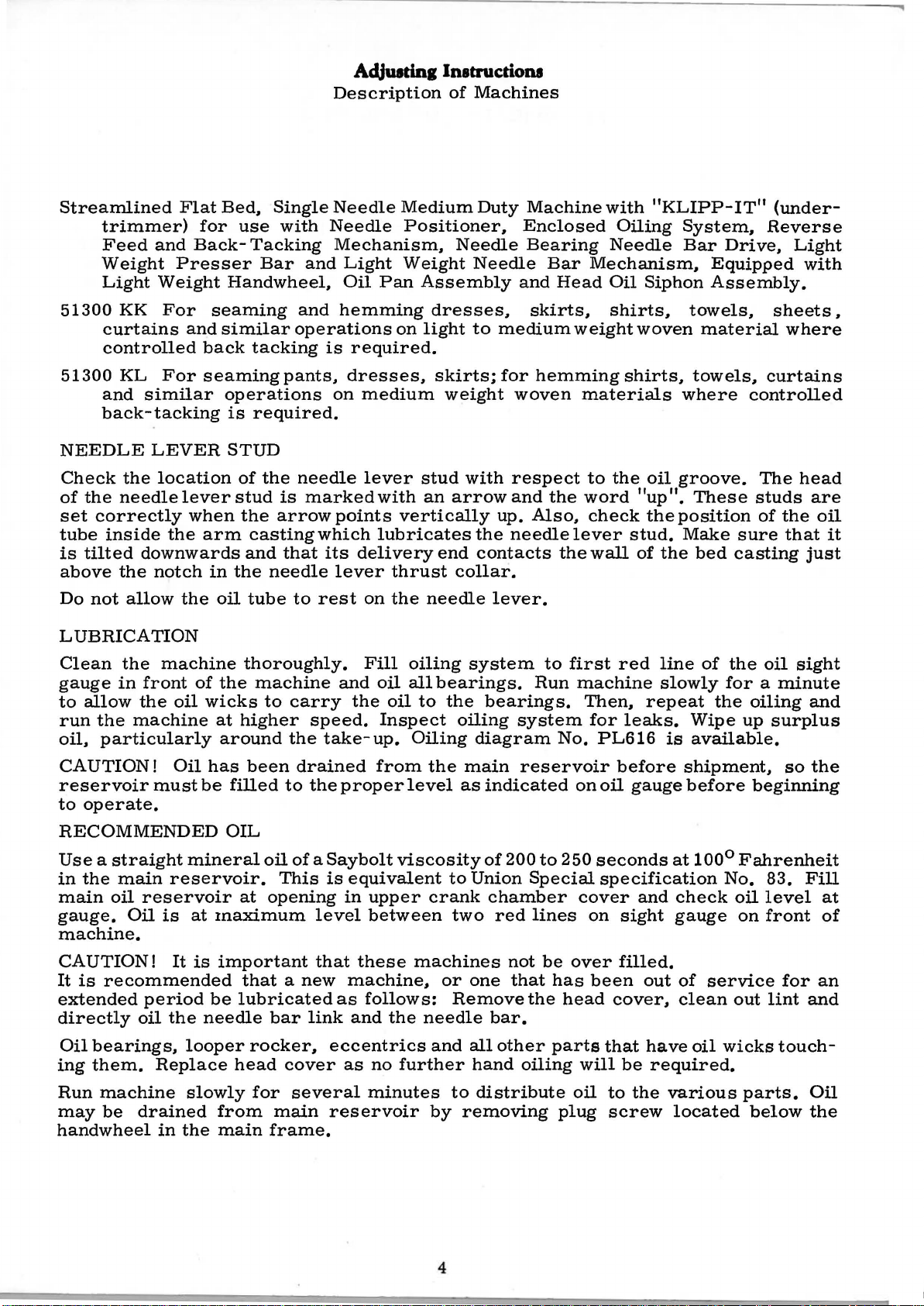
Streamlined
Flat
trimmer)
Feed
Weight
Light
51300
curtains
KK
and
Presser
Weight
For
and
controlled
51300
KL
and
For
similar
back-tacking
NEEDLE
Check
of
the
set
correctly
tube
is
tilted
above
Do
not
LEVER
the
needle
inside
downwards
the
notch
allow
location
lever
the
the
LUBRICATION
Bed.
for
use
Back-
Handwheel,
seaming
similar
back
seaming
operations
is
STUD
of
stud
when
arm
in
the
oil
Single
with
Tacking
Bar
operations
tacking
pants,
required.
the
is
the
arrow
casting
and
that
needle
tube
to
Needle
Needle
Mechanism.
and
Light
Oil
and
hemming
is
required.
dresses,
on
needle
marked
points
which
its
lever
rest
Medium
Positioner.
Weight
Pan
on
medium
lever
with
vertically
lubricates
delivery
thrust
on
the
Duty
Needle
Needle
Assembly
dresses,
light
to
skirts;
weight
stud
with
an
arrow
the
end
contacts
collar.
needle
lever.
Machine
Enclosed
Bearing
Bar
and
skirts.
medium
for
hemming
woven
respect
and
the
up.
Also,
needle
with
Needle
Mechanism,
Head
Oil
shirts,
weight
materials
to
the
word 11up
check
lever
the
wall
"KLIPP-
Oiling
Siphon
woven
shirts,
oil
the
stud.
of
the
System.
Bar
Equipped
Assembly.
towels,
material
towels,
where
groove.
11
•
These
position
Make
bed
IT"
(under-
Reverse
Drive,
sheets.
curtains
controlled
The
studs
of
sure
casting
Light
with
where
head
are
the
oil
that
just
it
Clean
gauge
to
run
oil,
CAUTION!
reservoir
to
the
in
front
allow
the
the
machine
particularly
must
operate.
machine
of
oil
Oil
be
RECOMMENDED
Use a straight
in
the
main
main
gauge.
oil
Oil
mineral
reservoir.
reservoir
is
at
machine.
CAUTION!
It
is
recommended
extended
directly
Oil
bearings,
ing
them.
Run
machine
may
be
handwheel
It
period
oil
the
looper
Replace
slowly
drained
in
the
is
needle
thoroughly.
the
machine
wicks
at
to
higher
around
has
been
filled
OIL
oil
at
opening
maximum
important
that a new
be
lubricated
rocker,
head
for
from
main
carry
speed.
the
take-up.
drained
to
the
of a Saybolt
This
is
level
that
bar
link
eccentrics
cover
several
main
reservoir
frame.
Fill
and
oil
the
oil
Inspect
from
proper
viscosity
equivalent
in
upper
between
these
machine,
as
follows:
and
the
as
no
further
minutes
oiling
all
to
system
bearings.
the
oiling
Oiling
the
main
level
as
to
crank
two
machines
or
one
Remove
needle
and
all
to
by
removing
Run
bearings.
system
diagram
reservoir
indicated
of
200
Union
Special
chamber
red
lines
not
that
the
bar.
other
hand
oiling
distribute
to
No.
to
be
has
parts
plug
250
head
first
red
machine
Then,
for
leaks.
PL616
before
on
oil
gauge
seconds
specification
cover
on
over
and
sight
filled.
been
cover,
that
will
be
oil
to
the
screw
line
of
slowly
repeat
Wipe
is
available.
shipment,
before
at
100°
check
gauge
out
of
clean
have
oil
required.
various
located
the
oil
for a minute
the
oiling
up
surplus
so
beginning
Fahrenheit
No.
83.
oil
level
on
front
service
out
wicks
for
lint
touch-
parts.
below
sight
and
the
Fill
at
of
an
and
Oil
the
4
Page 7
Adjuadn1Inetructions
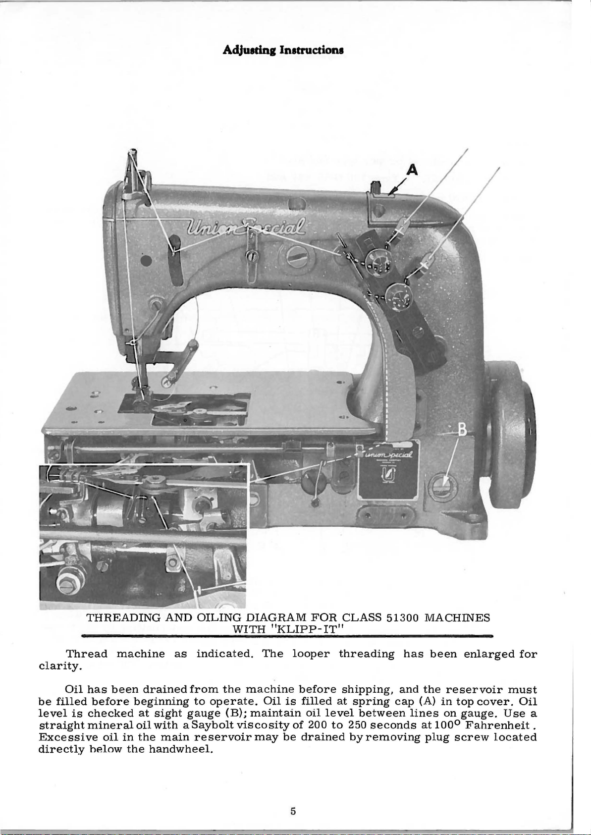
Thread
clarity.
Oil
be
filled
level
straight
Excessive
directly
is
THREADING
machine
has
been
before
checked
mineral
oil
helow
beginning
in
the
AND
as
drained
at
sight
oil
with a Saybolt
the
handwheel.
from
gauge
main
OILING
indicated.
to
operate.
reservoirmay
DIAGRAM
WITH
the
machine
(B);
maintain
viscosity
"KLIPP-
The
Oil
is
be
FOR
looper
before
filled
oil
of
200
drained
5
CLASS
IT"
threading
shipping,
at
spring
level
to
250
byremoving
between
51300
has
and
cap
seconds
MACHINES
been
the
reservoir
(A)
in
lines
at
100°
plug
on
screw
enlarged
top
cover.
gauge.
Fahrenheit.
located
must
Oil
Use
for
a
Page 8
NEEDLE
Put
in a new 'needle
For
Style
for
Style
51300
51300
KK
KL
of
proper
Type
Type
Adjuatin1 Instructions
type
and
size.
130
130
GHS-036
GHS-040
and
Place
the
and
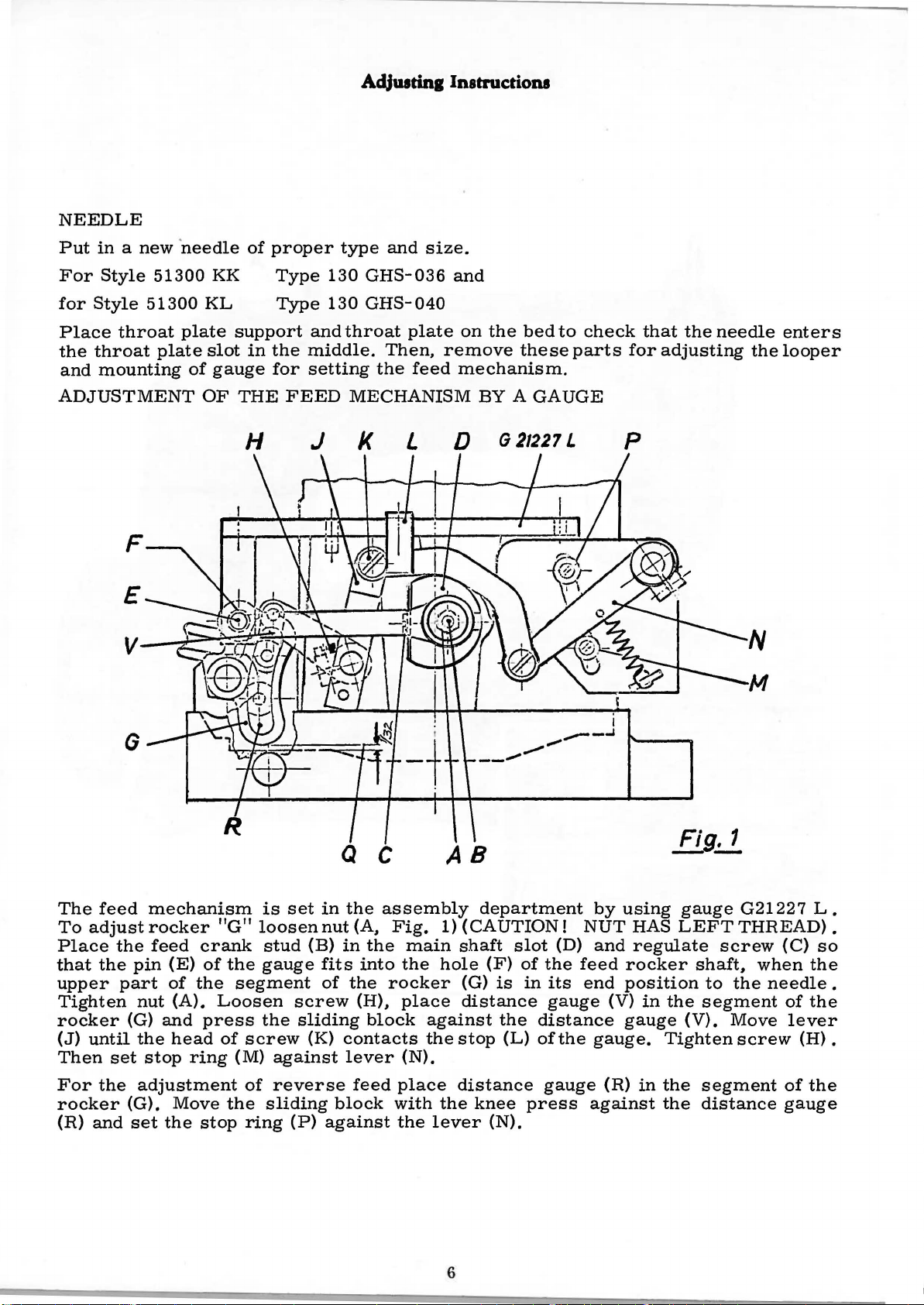
ADJUSTMENT
throat
throat
mounting
plate
F
E
G
plate
slot
of
gauge
OF
support
in
the
for
THE
FEED
H
and
throat
middle.
setting
MECHANISM
J
K
plate
Then,
the
L
on
remove
feed
mechanism.
BY A GAUGE
D G21227 L
__
the
.,.,
bed
these
_,.,.,
to
check
parts
----'
I
that
for
p
the
needle
adjusting
the
N
M
enters
looper
The
feed
To
adjust
Place
that
the
upper
Tighten
rocker
(J)
until
Then
For
rocker
(R)
set
the
and
mechanism
rocker
the
feed
pin
(E)
part
of
nut
(A).
(G)
and
the
head
stop
adjustment
(G).
Move
set
the
crank
of
the
press
ring
stop
is
"G"
loosen
stud
the
gauge
segment
Loosen
the
of
screw
(M)
of
the
sliding
ring
set
in
nut
(B)
fits
of
screw
sliding
(K)
against
reverse
(P)
Q c
the
(A.
in
the
into
the
(H).
block
contacts
lever
feed
block
against
assembly
Fig.
rocker
place
with
the
main
the
place
against
the
(N).
lever
AB
department
1)
(CAUTION!
shaft
hole
(F)
(G)
is
distance
the
stop
(L)
distance
the
knee
(N).
6
slot
of
the
in
its
gauge
distance
of
gauge
press
(D)
the
by
NUT
and
feed
end
(V)
gauge.
(R)
against
Fig. 1
--
using
HAS
LEFT
regulate
rocker
position
in
the
gauge
Tighten
in
the
the
gauge
screw
shaft.
to
segment
(V).
segment
distance
G21227
THREAD).
(C)
when
the
needle
of
Move
screw
lever
(H).
of
gauge
L.
so
the
.
the
the
Page 9
AdJutrinl Instructions
ADJUSTMENT
After
both
CAUTION!
(G)
If
(M)
All
loosening
ADJUSTMENT
this
directions.
AND
a
other
THE
larger
downwards.
stitch
adjustment
BE
stitch
the
H J
OF
SURE
BED
length
nut
OF
THE
For
AT
length
(A)
THE
FEED
the
stitch
correction
THAT
changes
of
THE
than
the
FEED
THERE
LARGEST
8 1 I 2
feed
MECHANISM
length
reset
stitches
must
crank
MECHANISM
IS
be
stop
1132
stud
should
STITCH
made
BY A GAUGE
be
about
ring
(M).
INCH
per
(B).
SPACE
LENGTH
inch
is
by
the
stitch
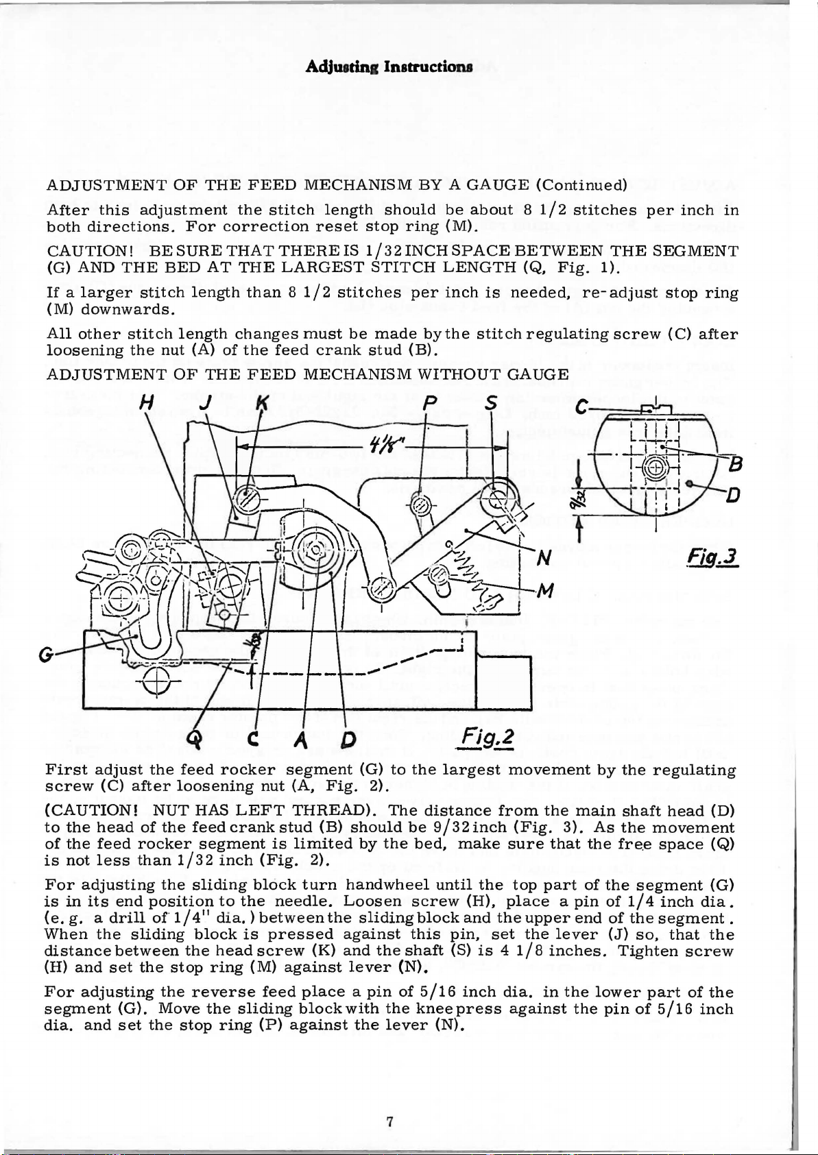
WITHOUT
s
(Continued)
8 1 I 2
BETWEEN
(Q,
needed,
regulating
GAUGE
stitches
Fig.
THE
1).
re-adjust
screw
per
inch
SEGMENT
stop
ring
(C)
after
in
G
First
screw
(CAUTION!
to
of
is
For
is
(e.
When
distance
(H)
For
segment
dia.
adjust
(C)
the
head
the
feed
not
less
adjusting
in
its
g. a drill
the
and
set
adjusting
and
the
after
NUT
of
the
rocker
than
the
end
position
of
sliding
between
the
the
(G).
Move
set
the
feed
rocker
loosening
HAS
feed
segment
1 I 3 2
114
stop
sliding
11
block
the
ring
reverse
the
stop
inch
to
dia.)
head
ring
nut
LEFT
crank
(Fig.
block
the
between
is
screw
(M)
feed
sliding
(P)
segment
(A,
THREAD).
stud
is
limited
2).
turn
needle.
pressed
(K)
against
place a pin
blockwith
against
_,
(G)
Fig.
(B)
should
by
handwheel
Loosen
the
sliding
against
and
lever
the
......
2).
the
......
to
The
be
the
shaft
(N).
of
the
lever
the
screw
this
I
--.&
-
Fig,2
·--
largest
distance
9l32inch
bed,
kneepress
until
block
5 I
16
(N).
make
(H),
and
pin,
(S)
inch
movement
from
(Fig.
sure
the
top
place a pin
the
upper
set
the
is 4 118
dia.
against
the
main
3).
that
part
end
lever
inches.
in
the
the
by
As
the
of
the
of
lower
pin
the
shaft
the
fre.e
segment
114
of
the
(J)
so,
Tighten
of
regulating
head
movement
space
inch
dia.
segment.
that
the
screw
part
of
the
5116
inch
(D)
(Q)
(G)
7
Page 10
AcUuttintE
Instructions
ADJUSTMENT
After
directions.
If
(M)
All
loosening
LOOPER
Insert
The
point
ment
in
For
After
ball
LOOPER
When
as
this
a
larger
downwards.
other
looper
making
the
joints
possible
stitch
ADJUSTMENT
the
looper
of
the
should
looper
the
right
A VOID
the
looper
adjustment
For
stitch
the
gauge
looper
be
this
have
without
OF
THE
the
correction
length
length
nut
(A)
of
in
the
represents
when
5/32
adjustment.
gauge
gauge
inch.
adjustment
is
clearance
MOTION
moves
contacting.
FEED
stitch
reset
than 8 1/2
changes
the
feed
looper
the
the
looper
Looper
set.
tighten
in
all
to
the
left.
MECHANISM
length
must
crank
rocker.
measurement
positions.
should
stop
stitches
be
is
at
gauge
loosen
the
its
point
ring
made
stud
Notice
the
No.
the
nuts
WITHOUT
be
about 8 1/2
(M).
per
inch
by
the
(B).
that
from
right
21225-5/32
two
nuts
securely.
should
pass
stitch
the
the
end
GAUGE
stitches
is
needed.
regulating
screw
centerline
of
the
can
on
the
Notice
the
rear
(Continued)
re-adjust
rests
stroke.
looper
be
that
of
on
of
used
the
the
per
inch
in
stop
screw
the
the
This
advantageously
connecting
connecting
needle
(C)
looper
needle
measure-
as
after
flat.
to
rod.
close
both
ring
the
rod
SYNCHRONIZING
Use
gauge
rocker.
for
attaching.
wire
Turn
edge
against
set
until
on
scale
in
rear.
the
drive
Then
distorting
front
between
the
Gasket
is
Automobile
holder
of
screw
the
the
operating
oil
rear.
identified
No.
Place
with
handwheel
the
gauge
the
top
and
pin
again
indicator
is
allowable.
direction.
If
the
reading
reservoir
eccentric
drive
and
the
the
parts
place a horse
the
looper
Retighten
Cement
by
supply
21227
the
Place
of
note
will
mechanism
rear
to
the
LOOPER
R.
gauge
the
the
pointer
in
operating
plate
the
needle
indicator
contacts
return
If
the
is
top
cover
bushing
remove
drive
all
prevent
symbol
shops
Insert
plate
indicator
and
to
reading
the
lower.
and
shoe
lever
screws
oil
"CE5C".
carry
AND
the
on
to
the
direction
set
the
bar
and
reading.
the
plate.
the
is
looper
this
drain
and
move
to
the
the
plug
shape
and
and
leakage.
it.
NEEDLE
pin.
the
portion
same
rocker
seal
which
throat
right.
until
indicator
the
right
Turn
If
reading.
higher
drive
the
reservoir.
the
front
screw
metal
the
and
or
adjacent
the
A
will
MOTIONS
is
included
plate
of
the
Do
not
the
pin
so
that
end
of
the
handwheel
motions
A
on
the
lever
will
eccentric
convenient
rocker
have
the
middle
in
the
washer
bushing
reservoir
be
promptly
with
seat
using
gauge
tighten
are
variation
scale
to
rear
in
the
in
the
looper
the
left
the
pointer
in
synchronization
when
will
be
moved
Loosen
as
far
bushing
bushing
approximately
when
cover
1/2
pint
furnished
the
the
the
needle
set
end
in
of
the
have
the
to
the
driving
in
position
can.
gauge.
throat
thread
screw
rocker
of
the
rests
the
one
to
screws
to
before
at
reverse
graduation
handwheel
to
be
the
front.
right
the
rear.
1/16
with
including
by
Union
in
the
plate
at
this
contacts
pointer
"O".
direction
the
is
moved
in
the
as
it
driving
inch
the
bushing
Permatex
looper
screws
take-
time.
the
rests
Tighten
pointer
on
the
turned
to
the
Remove
looper
will
go.
To
avoid
to
the
thick
brush.
Special.
up
to
If
the
Insert
gauge
the
is
not
looper
available.
in
the
looper
synchronization
rocker
and
B
turn
may
the
be
pulley
checked
in
as
the
operating
follows:
direction
Page 11
Aclluatinllnatructiona
SYNCHRONIZING
until
of
reverse
needle.
to
distance
is
NEEDLE
Set
looper,
When
RETAINING
Adjust
travel
or
has
the
the
the
the
turned
Moving
the
tacking,
forth
1/32
needle.
looper
eye
of
direction
If
the
looper
from
in
it
in
BAR
needle
when
the
to
the
in
its
inch
point
the
motions
point
the
operating
the
opposite
bar
point
skip
FINGER
retaining
left
adjustment
clearance
LOOPER
moves
needle
until
will
eye
of
so
that
of
looper
stitches
DRIVE
arm
is
1/8
AND
with
the
looper
synchronize,
be
the
the
needle
direction,
direction
the
in
inch
so
that
back
to
the
respect
same.
top
moving
may
or
out
from
the
of
the
NEEDLE
occur
left
to
point
the
to
the
move
acts
of
the
to
of
center
hook
needle.
MOTIONS
and
the
again
height
A
variation
point
the
the
needle
the
if
the
its
slot
line
point,
is
even
looper
moves
of
of
the
looper
reverse.
eye
left
is
needle
so
of
when
No
part
(Continued)
with
point,
to
the
eye
of.
005
looper
drive
is
less
even
is
set
that
the
needle.
passing
of
the
the
then
the
of
is
lever
with
too
hook
Set
hook
needle.
turn
left
the
inch
longest
than
left
low.
the
the
the
and
is
needle
is
allowable.
when
rocker
1/64
side
point
pivot
back
should
Note
pulley
even
with
to
inch
of
at
bracket
of
ever
the
the
the
below
the
its
the
height
in
the
with
the
respect
If
the
pulley
rear.
the
needle
furthest
back
needle,
contact
.
TIMING
To
time
the
looper
the
vertical
crank
vertical
If
the
except
first
drive
retainer
shaft
If
the
FRONT
Set
higher
as
tacking
possible.
shaft
the
retainer
oil
be
should
drive
the
crank
retainer
the
the
looper
THE
the
retainer
drive
shaft.
by
crank
chamber
the
main
turned
be
drive
gear
shaft
timing
NEEDLE
front
than
if
needle
the
the
See
RETAINER
drive
lever,
Set
the
hand
point
front
paragraph
(gripping
check
gear
over
positioned
set
looper
lines
drive
top
cover,
shaft
so
as
above
and
the
does
will
GUARD
guard
point,
comes
guard
gear.
insert
needle
is
that
driven
not
turn,
be
high
up
is
for
remove
screw
the
up
with
located
the
entire
When
the
needle
so
the
can
then
gear
the
correct.
enough
and
to
the
not
as
setting
access
bar
crank
the
properly
the
timing
be
cover
Check
so
that
needle.
high
rear
driver
at
the
strap)
timing
retainer
cover
is
at
rnarks
put
mesh
so
the
as
needle
plug
and
bottom
until
mark
and
is
the
bottom
in
place
together
screws
the
timing
that
its
guarding
Needle
possible
screw
loosen
of
the
on
if
it
drive
to
be
are
being
can
top
breakage
guard.
in
casting
screws
the
stroke
timing
the
top
becomes
will
lift
replaced,
of
its
in
line.
careful
the
crank
be
inserted
to
be
surface
surface
and
the
just
in
the
and
mark
cover.
necessary
off
the
stroke,
The
top
that,
shaft
sure .it
is
as
just
contacts
will
rear
driven
turn
on
the
with
machine
and
cover
does
and
is
high
occur
guard
to
the
right
gear
the
vertical
face
to
remove
the
top
the
retainer
with
when
correct.
the
not
tightened
or
slightly
the
when
as
on
of
the
cover
should
the
main
turn.
and
needle
back-
low
as
of
9
Page 12
AdJUJrinl
Instruction~
FEED
Set
throat
dog,
Check
approach.
REAR
The
to
THREADING
Thread
tests.
LOOPER
The
equal
on
When
the
The
the
amount
has
thread
DOG
the
feed
plate
to
maintain
clearance
NEEDLE
needle
the
left -is . 005
the
THREAD
looper
clearance
the
main
the
needle
discs
needle
clearance
looper
of
just
must
has
slack
must
ADJUSTMENT
dog
so
that
the
at
highest
GUARD
barely
THE
machine
thread
on
shaft
moves
come
thread
entered
thread
between
after
this
the
point
setting.
between
contact
inch
MACHINE
according
TAKE-UP
take-up
each
and
consequently
down
out
of
must
cast
the
in
the
eye
tips
of
top
before
must
side
the
off
triangle
the
two
of
the
of
travel.
of
retainer
the
the
to
be
of
the
and
the
cast-
from
system
discs
needle
the
teeth
Adjust
needle
right
threading
placed
shield.
can
off
deep
of
be
looper
plate
the
highest
enough.
and
must
the
comes
guard
edge
are
parallel
the
hook
when
of
diagram
on
the
The
looper
set
to
starts
to
take
be
take-up
up
with
supporting
and
bottom
the
point
the
needle.
No.
main
compensate
lob
The
set
out
its
the
of
and
of
shaft
thread
movement
slack
the
retaining
on
the
so
that
the
and
3 I
screw,
of
feed
of
the
PL616
so
that
take-
for
varying
from
take-
cast-
material.
the
up
finger
off
it
releases
64
inch
above
under
dog
looper -moving
and
start
both
up
is
from
looper
when
plate
the
at
closest
sewing
discs
not
conditions
left
the
controls
the
spotted
to
thread
point
so
that
looper
have
right
the
feed
•
.
of
the
it
THREAD
The
looper
tension
skips.
NEEDLE
It
above
50-2 cord
feeding.
PRESSER
See
ment
PRESSER
The
bar.
Set
may
that
with
presser
Turning
the
If
not
the
pressure
TENSION
thread
is
too
low,
the
tension
THREAD
be
necessary
needle
or
heavier,
FOOT
the
presser
the
feed
FOOT
spring
it
tension
the
is
NIPPER
if
light
the
foot
dog
PRESSURE
adjusting
clockwise
only
high
should
take-
too
high
to
use
thread,
nipper
hinges
and
the
increases
enough
up
may
the
the
under
freely
throat
screw
be
about
lose
stitch
needle
spring
plate.
is
the
pressure,
to
feed
1 I 4
control
may
be
thread
60-2 cord,
helps
and
the
properly.
to
that
knurled
of
the
needle
over
pulled
nipper
is
throw a needle
its
under
screw
counterclockwise
the
down.
in
used.
surface
front
If
directly
thread
thread
heavy
loop
is
tension.
causing
of
the
thread
when
in
lateral
behind
acts
casting
is
the
the
reverse.
If
the
triangle
just
used,
reverse
align-
needle
10
Page 13
Adj111tiq lnatructiona
NEEDLE
Set
the
as
low
Raise
NEEDLE
Set
the
studis
necessary
frame
lowering a smaller
SEAM
Check
a
triangular
too
sharp.
Check
worse
With
in
the
ADJUSTMENT
THREAD
needle
as
possible.
it
only
THREAD
needle
in
the
middle
eyelet
CONTROL
the
seam
oil
that
the
if
the
teeth
all
of
the
following
thread
if
needle
thread
if
thread
influences
produced
stone
machine
electrical
sequence:
OF
TAKE-UP
take-
loop
FRAME
frame
of
its
slot.
breakage
the
needle
for
polishing
chains
are
too
ADJUSTING
plug-connections
CUTTING
WIRE
up
wire
skips
EYELET
eyelet
Raising
occurs,
size
thread
for
chafed
off
highly
SOLENOID
(strike-
occur
(No.
it
brings
of
the
needle
loop.
or
the
middle
well
polished.
"KLIPP-IT"
off)
located
and
cannot
539)
located
better
at
cross
thread
cut
threads
row
without
disconnected,
STROKE
chafing
MECHANISM
to
be
corrected
to
needle
seams.
loop.
by
of
the
the
right
the
left
thread
The
position
Raising
unravelling
feed
dog
the
chain.
adjustments
of
the
needle
any
other
of
the
pull
causes a larger,
the
teeth
Chaining
should
needle
up.
Lowering
of
the
stitch.
which
way.
be
bar
lever
thread
Apply
may
will
made
,
be
be
I
1
I
(
armature
the
rear
be
required.
shaft
of th·e
loosen
Fig.
(A,
Fig.
needle
screws
4
(B)
4)
observing
as
close
(C),
that
as
possible
reposition
B
c
knife
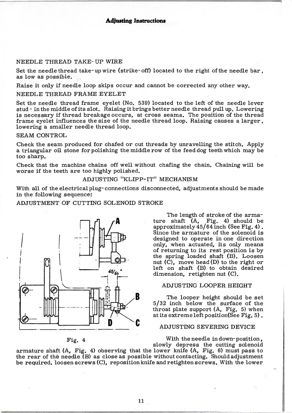
The
ture
approximately
Since
designed
only,
of
returning
the
spring
nut
(C),
left
on
dimension,
ADJUSTING
The
5 I 3
~
throat
at
its
ADJUSTING
With
slowly
the
lower
without
and
retighten
length
shaft
the
armature
to
when
move
shaft
looper
inch
extreme
below
plate
theneedle
depress
knife
contacting.
of
stroke
(A,
operate
actuated,
to
loaded
retighten
support
(A,
Fig.
4 5 I 6 4
its
head
(B)
LOOPER
height
left
position(See
SEVERING
the
Fig.
screws.
of
the
4)
should
inch
(See
Fig.
of
the
solenoid
in
one
direction
its
only
rest
position
shaft
(D)
to
the
indown-position,
Should
(B).
to
obtain
nut
should
surface
(A,
Fig.
cutting
6)
must
With
Loosen
the
right
desired
(C).
HEIGHT
5)
Fig.
DEVICE
solenoid
pass
adjustment
the
arma-
be
4) .
is
means
is
by
or
be
set
of
the
when
5).
to
lower
11
Page 14
AdJUJtiaa
lrutructioru
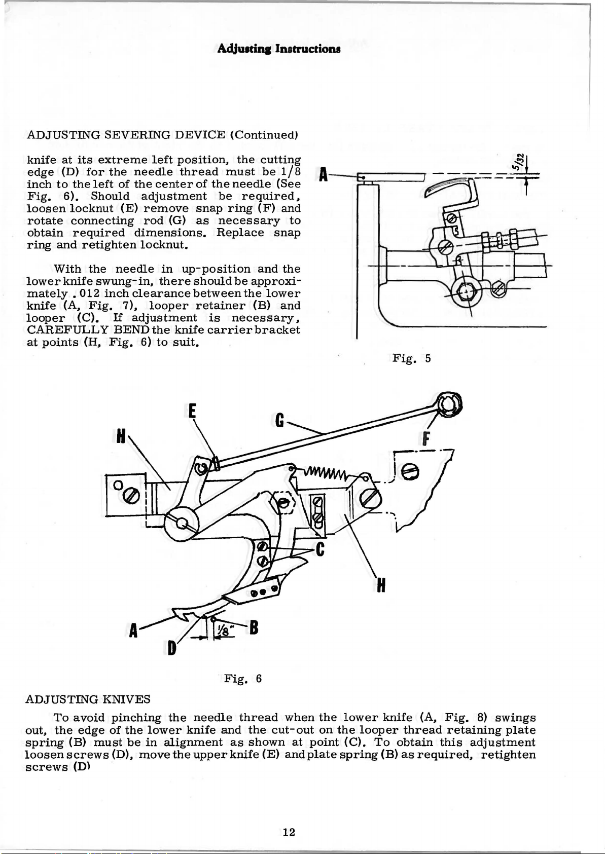
ADJUSTING
knife
edge
inch
Fig.
loosen
rotate
obtain
ring
lower
mately • 012
knife
looper
CAREFULLY
at
at
(D)
to
6).
locknut
and
With
knife
(A,
points
its
extreme
for
the
left
Should
connecting
required
retighten
the
swung-in,
Fig.
(C).
(H,
SEVERING
left
the
needle
of
the
center
adjustment
(E)
remove
rod
dimensions.
locknut.
needle
inch
7),
If
BEND
Fig.
in
there
clearance
looper
adjustment
the
6)
to
DEVICE
position,
thread
of
the
snap
(G)
as
up-position
should
between
retainer
is
knife
suit.
carrier
(Continued)
the
cutting
must
be
ring
necessary
Replace
be
needle
required,
(F)
and
be
approxi-
the
(B)
necessary,
bracket
1/8
(See
and
to
snap
the
lower
and
. N
~I
A---..~c.-----..,.
Fig.
----
5
---
-·~
T
ADJUSTING
To
avoid
out,
the
edge
spring
loosen
screws
(B)
screws
(D) -
H
KNIVES
pinching
of
the
must
(D),
be
move
the
lower
in
alignment
the
needle
knife
upper
Fig.
and
as
knife
6
thread
the
shown
(E)
when
cut-out
at
and
the
on
point
plate
lower
the
looper
(C).
spring
r-·-·
te
·""
knife
To
(B)
F
(A,
thread
obtain
as
required,
Fig.
retaining
this
adjustment
8)
swings
plate
retighten
12
Page 15
A
Ac:IJUitinainatructiona
A
B
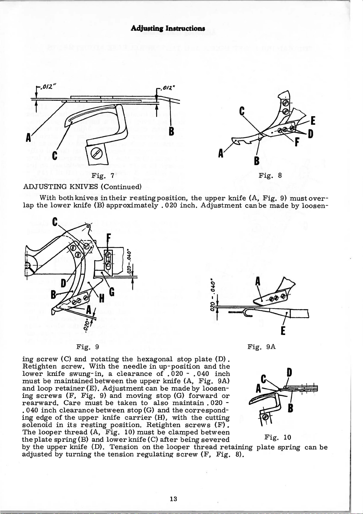
ADJUSTING
lap
With
the
both
lower
Fig.
KNIVES
knives
knife
Fig.
(B)
9
7
(Continued)
in
their
approximately . 020
resting
position,
the
inch.
upper
Adjustment
knife
•
C)
....
C)
I
()
~*=t
=~~:::;:.._
(A,
can
Fig.
Fig.
Fig.
be
9A
8
9)
made
__
must
by
loosen-
over-
,
ing
screw
Retighten
lower
must
and
ing
rearward.
.
ing
solenoid
The
the
by
adjusted
040
plate
the
be
loop
screws
inch
edge
looper
(C)
screw.
knife
upper
swung-in,
maintained
retainer
(F,
Care
clearance
of
the
in
its
thread
spring
knife
by
turning
and
(E).
Fig.
must
upper
resting
(B)
rotating
With
the
a
between
Adjustment
9)
and
be
between
knife
(A,
Fig.
and
lower
(D).
the
Tension
tension
the
needle
clearance
the
moving
taken
stop
carrier
position.
10)
knife
hexagonal
in
up-position
of . 020
upper
to
(G)
must
on
regulating
knife
can
be
stop
also
and
(H),
Retighten
be
(C)
after
the
stop
plate
and
- .
040
(A,
Fig.
made
maintain . 020
the
with
clamped
looper
13
by
(G)
forward
correspond-
the
screws
being
thread
screw
loosen-
cutting
between
severed
(F,
(D) .
the
inch
9A)
(F).
retaining
Fig.
or
-
8).
Fig.
plate
10
spring
can
be
Page 16
AdjUitinglnatructiona
F
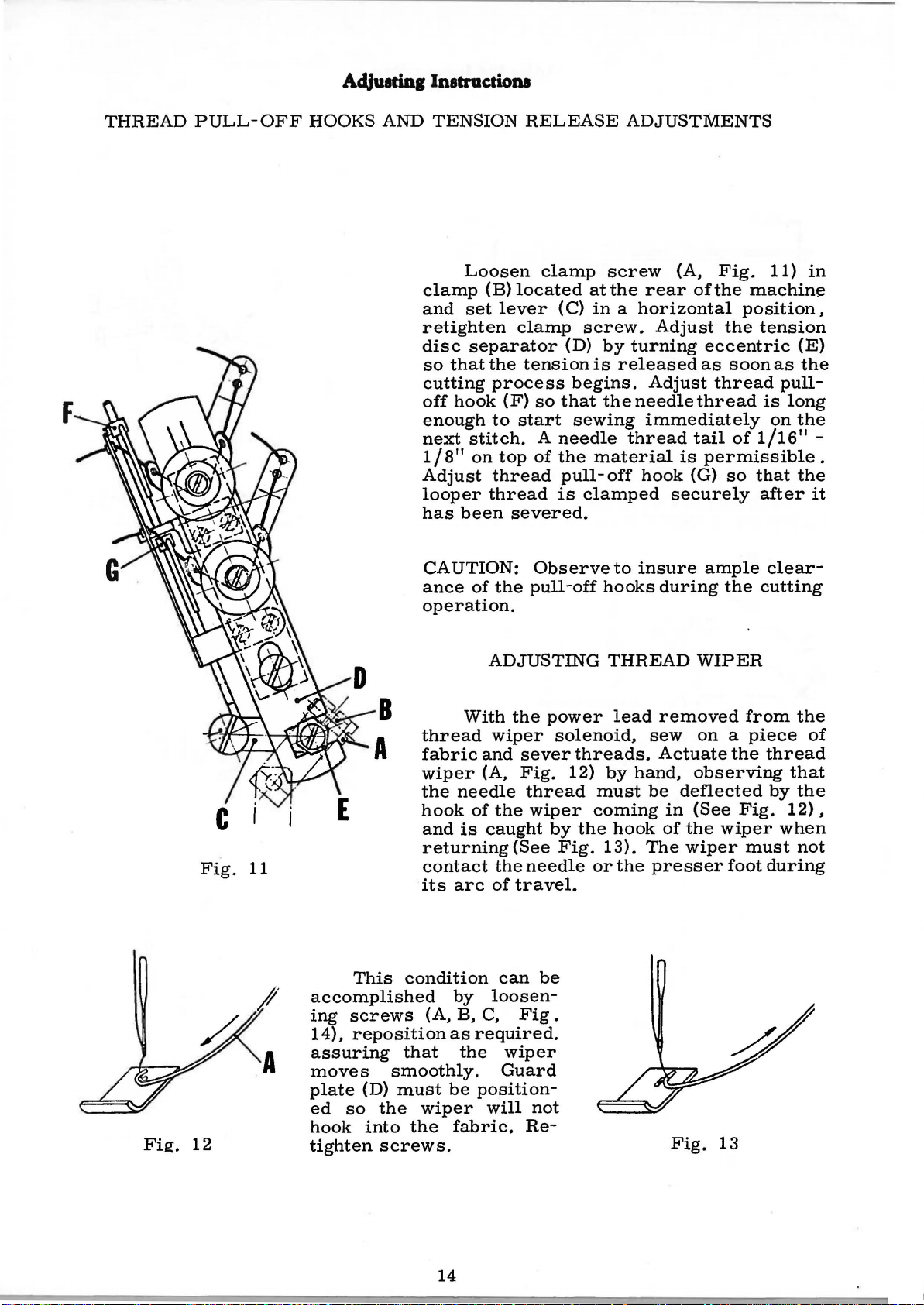
THREAD
PULL-
OFF
HOOKS
AND
clamp
and
retighten
disc
so
cutting
off
enough
next
1/8"
Adjust
looper
has
CAUTION:
ance
operation.
TENSION
Loosen
(B)
set
lever
separator
that
the
process
hook
to
stitch.
on
thread
thread
been
of
the
(F)
top
RELEASE
clamp
located
(C)
clamp
(D)
tension
begins.
so
that
start
severed.
sewing
A
needle
of
the
pull-
is
Observeto
pull-off
ADJUSTMENTS
screw
at
the
in a horizontal
screw.
by
is
released
the
thread
material
off
clamped
hooks
(A,
rear
turning
needle
immediately
hook
insure
ofthe
Adjust
Adjust
tail
is
(G)
securely
during
Fig.
eccentric
as
thread
thread
permissible.
ample
machine
position,
the
tension
soon
is
of
1/16"
so
that
after
clear-
the
cutting
11)
as
on
in
(E)
the
pull-
long
the
-
the
it
Fie:.
Fig.
12
11
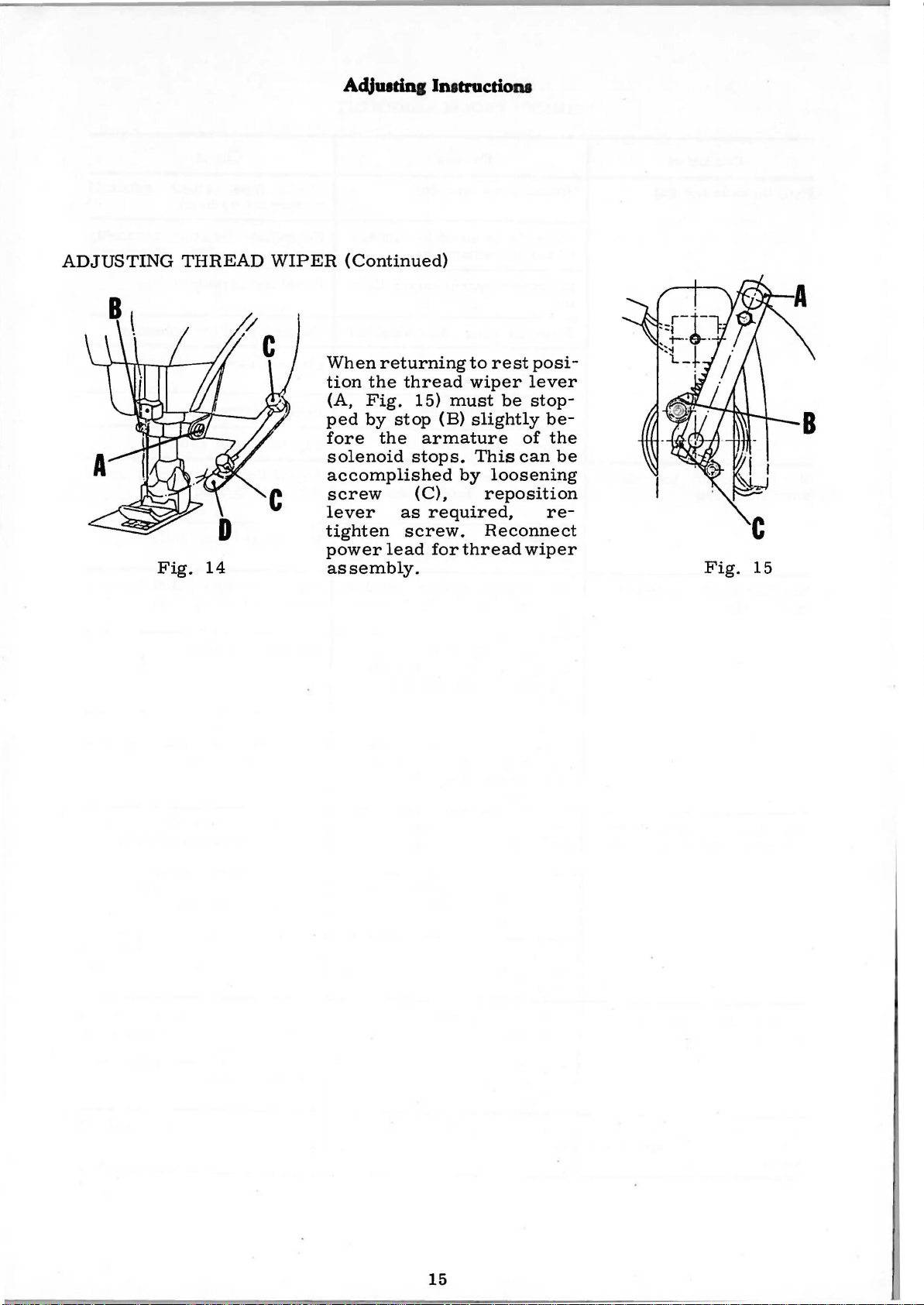
This
accomplished
ing
screws
14),
reposition
assuring
moves
plate
ed
so
hook
tighten
condition
that
smoothly.
(D)
must
the
into
screws.
With
thread
fabric
wiper
the
needle
hook
and
is
returning
contact
its
arc
by
(A,
B,
as
the
be
wiper
the
fabric.
ADJUSTING
the
power
wiper
and
sever
(A,
Fig.
thread
of
the
wiper
caught
the
of
can
loosen-
C,
required.
Guard
position-
will
by
(See
needle
travel.
be
Fig
wiper
not
Re-
THREAD
lead
solenoid,
threads.
12)
by
must
coming
the
hook
Fig.
13).
or
the
.
removed
sew
Actuate
hand,
be
in
of
The
presser
Fig.
WIPER
from
on a piece
the
observing
deflected
(See
Fig.
the
wiper
wiper
must
foot
13
the
of
thread
that
by
the
12),
when
not
during
14
Page 17
AdJUidnilnatructiona
ADJUSTING
Fig.
THREAD
14
WIPER
(Continued)
When
tion
(A,
ped
fore
solenoid
accomplished
screw
lever
tighten
power
assembly.
returning
the
thread
Fig.
by
15)
stop
the
stops.
(C),
as
screw.
lead
armature
to
rest
wiper
must
(B)
slightly
This
by
loosening
reposition
required,
Reconnect
for
thread
be
posi-
lever
stop-
be-
of
the
can
re-
wiper
be
Fig.
15
15
Page 18

TRIMMER
TROUBLESHOOTING
Both
threads
Needle
after
Needle
trim
cycle
Condition
thread
trimming
thread
not
cut
too
pinched
short
after
Solenoid
Solenoid
of
tension
Improper
ing
Solenoid
Power
connected
Bent
relay
Loose
Needle
too
bly
Lower
of
Not
between
knife
lower
high
knife
needle
enough
Causes
not
working
jammed
assembly
synchronizer
plug
lead
thread
on
loop
disconnected
to
contacts
knife
tension
trims
around
spring
upper
by
motor
pull-
both
and
linkage
tim-
not
off
set
assem-
sides
looper
tension
lower
Check
movement
Re-adjust
linkage
Reset
Connect
Connect
Reshape
Tighten
Adjust
for
Re-adjust
Adjust
upper
fuse,
synchronizer
thread
more
spring
and
Cures
by
tension
for
plug
motor
relay
lower
needle
lower
lower
check
hand
free
for
solenoid
power
contacts
knife
strike-
thread
knife
tension
knife
solenoid
assembly
movement
lead
off
lower
between
Machine
ing
after
Needle
th~ead
thread
not
does
not
trimming
cut
caught
start
but
sew-
looper
Lower
cut
in
ing
spring
perly
Dull
kirlfe
Upper
not
overlap
shearing
Thread
pull-
offs
Looper
and
properly
Looper
spring
thread
Lower
far
Lower
adjusted
tension
enough
knife
looper
and
tail
set
thread
thread
does
knife
to
knife
and
thread
not
aligned
lower
enough
too
short,
too
control
not
not
retain
does
the
not
clearance
retain-
knives
for
proper
thread
high
adjusted
retaining
looper
not
left
properly
pro-
do
cam,
move
Re-adjust
Replace
Re-adjust
Re-adjust
ficient
er
Re-adjust
trol
Remove
knives
Re-adjust
connecting
instructions)
Adjust
knives
needle
thread
cam,
lint
and
lower
knives
knives
pull-offs
thread
looper
and
tension
from
re-adjust
knife
rod
(see
knife
for
and
thread
between
knives
assembly
adjusting
suf-
loop-
con-
and
Too
much
side
top
starting
needle
of
to
sew
thread
garment
on
when
Needle
too
low
thread
pull-
off
set
16
Raise
needle
thread
pull-off
Page 19

INSTRUCTIONS
FOR
QUICK
NEEDLE
POSITIONER
17
Page 20

1-'
00
~~
J.Z4 MIJK
!
2l~S
~A«
O.c-KtT"2!/460
~
£11ZS
PM!"
s lii8Lif"
6
SEcn oH
""
C.C
11-<C
-e
65~-?4
Jr.I
JJI
ER
S/,F,Pt~
ED
H/T
RO
H
SM
...:,
..,....I
~
-
/1
~
1-
tt
1/
...
~
'-""'""-
1-
= = = = =
"'""""
"
rr
c-
47e
·=
,;::::::-
&:;t:;.0-410
-=.
!If'
=--=
,y
,,
I
I.
===~
~
,,
C.
I"
""""'
l)
,,
" "
3 .
II
I!
~
;v
.SYNCHRONIZ£12
NS7;QLUI77DV
IN
S7.llli.L "n-1£ t:;!UI
A
UXI
LJAI?Y
Pt.AC£
AFTlZR
ACCCieOING
STRU:'T/ONS
MA
TO 7/-1£
ACCaE'OIN4
SliPU':TKJNS.
£L£C7J?ICAL
I'?ACHI/IC
KVS771LUN4
Cf-1/N£.
ArTER
S£CUI?t.N4
HANOWH£EL
a)
7:41:"£
7J4CHCO
CH.t:ON!ZER
77-IE
FOUE'
/"'CJll:JtE'RilNEL.
h)
RUN
THROV6H
A::L/6
TI-t£
AUX.
C)
RUN
FRI:lM
TO
THE
,11/110
CONN
FOLLOWS:
GROUND,
ro
THC
~CAD
CAunON
OF
AS
TIONS
CONTROL
TO
.FURNISH£0 WITH
TO 71-1£
MilK£
CONNECTIONS:
THE:
TO
77-IE
IN
THE
TI-t£
TO
S
YNCRRONIZ£R
P£R
.
hi'Va:a.t,a:"
CK-S70P
IN
77-;C
77-1£
FOURPRON4Pl.U6AT-
77-1£
J./IE'E"
HOLE:
SOL..E:NO'O~L£
THE
"TO
THE
CONTROL PANE.L.
THRCC:
AUX.
POWER
ECT
THC:
YCLll)4f;HzNL£AO
,&OWER
THC
Ft:)
NOTE::
A0JLISTIN6
MOn:>R
BOY
,o<~S
INOICATEO.
77-;£
V4BL£Boq.e£)
"n-1£
ACCCSSQE'I£S
AOVU.STING
THE:
SYNCH.eONIZ~
ANO
TIM
OF
THE
ANO
PLU6
Pt..LI6
WIRe
OFiJ.J£
t.EAOS
INLET~
£./2
INLET.
CI-I£CK
SLIP/?IN4S
1NS71?t.IC-
IN 4
CABLE:
AO.:TUSTIN6
RXLOHIN6
£NO
E'ECEPTIC!.E
l./Na;c:'O'O'WO
FEI+'U.E
CONT1?0L
INL£T
&.ACK
J,.t
IN-
TI-l£:
n<o
SYN-
IN 77-IE
Pl.U6
PAN£L
AS
TO
L£AO
eLL
S£TTI
AND
IT
IN-
1T !N
.tWO
l7iVM
HOllJR
•C
N6
lV
99B·e.so
MA
IN CON
TROL
A'f
,
INCI-I/
N6
CONN£C~TOP
0£1/IC£
TO
INS
B£
748
998
VICE
(EX
·
.39543R
·e70
IS
TRA
~I
INCH
AVAI
.SE
N D
CHA26£)
Ill
oio
IN4 ~ •
LABLE:.
AND
I
IFUS£
I I
AUXILIARY OR/
1/£
THIS
S];QI.L.ATIONS
PARTS
POS/TIOIV£R.
C/RCuiTR'Y
A
Pt.AN06RAPH
ON
()LitCk'"-
51300KKOI?KL.
NS!
SHOWS
o.r
COHR:JNENT
S7l:JP
~
Kt.IPP•!T
800
NEECJL£
:ST·36Z.
IN·
RAe
Page 21

Adjusting Instructions
The
for
ions
Before
terminal
380
volts
are
included
SCHEMATIC
starting
strip
or
Delta
MOTOR
to
operate,
of
the
connection
on
the
AND
motor
wiring
CLUTCH
check
is
for
the
complished
on
quired,
switch
arm,
made
the
designed
220
volts
diagram
The
pitman
the
motor
located
which
as
a)
retighten
follows:
Turn
switch
switch
starts
ARM
main
to
three
furnished
clutch
rod,
by
plate,
actuates
ADJUSTMENTS
supply
accommodate
arm
loosening
on
the
in a clockwise
closes
running.
voltage
phase
when
screws.
the
set
A.
with
should
reposition
right
the
screw
C.
the
possible.
the
Adjustment
magnetic
and
with
either
Details
motor
point
three
the
hand
located
direction
the
the
motor
Star
of
both
(See
in
the
This
socket
clutch
of
side
auxiliary
of
clutch
below
wiring
connection
connect-
Fig.
direction
can
be
head
screws
arm
as re-
the
micro
the
clutch
should
the
micro
until
control
16).
of
ac
be
the
.
-
-
-
380V
c)
Now,
obtain
The
synchronizer,
into
the
corresponding
The
QUICK-STOP
the
auxiliary
iary
must
two
screws
Remove
Replacement
belt
to
can
and
purpose.
drive
be
maintained
To
replace
screws
from
the
guard.
Clutch
assure
be
accomplished
the
clutch.
that
Fig.
is
securing the
three
fan
free
16
make
correct
drive
belt
driven
the
the
carbon
screws
of
round
cover
play
the
Two . 012
should
to
round
clutch
one
setting
clutch
marked
motor
off
avoid
brush
belt
and
should
is
by
removing
more
arm
should
be
removed,
the
excesssive
belt,
belt
guard
holders
which
can
carbon
normally
never
and
b)
complete
of
the
switch.
and
sockets
be
main
remove
will
now
one . 020
motor.
and
of
allow
be
accomplished.
brushes.
engaged
spacers
Turn
direction
control
turn
auxiliary
on
the
cleaned
cleaned
Correct
wear
the
fan
pivot
the
magnetic
removal
be . 020
at
as
inch
the
set
to
stops
on
the
control
control
about
and
refilled
on
the
cover
it
to
the
of
- .
028
any
time
required,
spacers
screw
the
position
running.
set
screw
plugs
panel.
every
alignment
belt.
from
brake
the
Reassemble
inch
have
two
with
the
side. Remove
complete
but
with
the
located
been
in a counterclockwise
where
counterclockwise
may
years.
grease.
of
motor.
and
withdraw
care
brake.
between
provided
the
now
be
At this
The
the
idler
Loosen
the
magnetic
magnetic
must
Adjustment
the
auxiliary
inserted
time
auxil-
rollers
two
cap-
brushes.
brake
brake,
be
taken
motor
for
this
to
the
.
If
the
firmly.
rotated
arm
is
which
When
freely
lifted
is
clearly
clutch
arm
lifting
without
in
excess
recognizable
is
the
the
of . 020
in
braking position,
clutch
arm, a position
clutch
or
inch,
when
turning
the
brake
clutch
the
"V"
at
which
engaging must
disc
should
the
"V"
belt
19
belt
the
be
engage
pulley.
pulley
"V"
belt
obtained.
the
must
be
pulley
If
flywheel
the
braked
can
be
clutch
disc,
Page 22

Adjusting Instructions
The
carbon
In
auxiliary
Remove
remove
hood
On
suppressor
for
the
contact
circuit
ELECTRICAL
Before
ments
synchronizer
dust.
case
control.
and
the
auxiliary
or
disposes
and
should
MOTOR
of
trouble
The
the
two
the
three
the
round
rear
capacitor
one
the
of
control.
for
SYSTEM
synchronizer
be
made:
AND
caps
the
of
closing
CLUTCH
should
at
following items
screws
belt.
control
and a tuning
two
REPLACE
be
the
auxiliary
of
the
securing the
When
change-
the
SYNCHRONIZER
is
ARM
cleaned
carbon
plate
capacitor;
the
contactor
over
brake
THE
installed
ADJUSTMENTS
periodically
control
require
brush
are
contacts,
coil circuit.
CONTROL
on
it
will
removal:
holder
magnetic
installed:
the
fails
ADJUSTMENTS
the
machine,
with a clean
be
useful
and
remove
casin
the
control
to
function,
one
for
IN
CASE
PLATE.
(Continued)
to
replace
the
g,
the
belt
rectifier,
plate
the
also
check
closing the
OF
TROUBLE
following basic
cloth
carbon
contactor,
to
remove
the
entire
brushes.
guard,
contains a fuse
the
magnet
the
fuse.
IN
adjust-
The
coil
THE
fan
arc
NOTE:
Synchronizer
Supporting
~-1
Bands
Part
-·-~L
are
to
be
rotated
'-------,7"'---
..__
_ _,_ _
......._+----+----
'----=='=-'----Cutting-
__
in
the
operating
Needle
Needle
Permanent
down
up
C
ontact
-
Contact
direction
of
the
Distance
lators
as
measured
shown
machine.
of
iso-
above
Fi
g.
17
1.
2.
3.
Loosen
insulated
While
insulated
Retighten
urements
screw
area
retaining
area
screw
(See
(A,
Fig.
15/64
this
1 3 I 3 2
(A)
Fig.
17)
inch
position,
inch
noting
17).
and
from
from
that
rotate
the
end
rotate
the
these
band
of
the
band
end
of
the
dimensions
20
(B)
to
insulated
(D)
to
insulated
position
area
position
are
to
area
be
the
of
the
of
set
beginning
band
beginning
band
by
(C).
(B).
cord
of
its
of
its
meas-
Page 23

Adjusting Instructions
With
the
pulley.
Push
within • 012
the
set
screws
the
aforementioned
The
needle
travel.
(B)
If
constant
adjustment
DESCRIPTION
START
SEWING
Treadle
switch
tioner
it
is
lever
drive
closes
by
slipping -see
cutting
the
button
inch
after
on
the
bar
rotate
band
OF
is
pushed
ZSH
118.
and
engages
actuating
instruction).
SYNCHRONIZER
solenoid
switch
its
disconnected,
for
extreme
uppermost
synchronizer
condition.
should
is
required,
{D)
WIRING
down
Retighten
stop
about . 020
slightly,
DIAGRAM
forwardly
Relay 1 is
solenoid
the
switch
lever
ADJUSTMENTS
assemble
needle
up-position.
travel
unit
and
advance
set
screws.
inch
loosen
to
energized.
clutch.
screw
attain
FOR
and
{Micro
ZSH
desired
QUICK-STOP-MOTOR
thereby
Contact
118
(Continued)
the
in
the
or
before
(A,
Fig. 1 7)
conditions,
micro
R11
switch
before
synchronizer
If
the
needle
operating
retard
reaching
and
switch
disengages
Mh
must
the
mechanical
bar
direction,
as
required
its
lowest
while
retighten
FK
Mh
be
adjusted
to
the
does
holding
screw
2/UNION
is
brake
motor
machine
not
loosen
to
obtain
point
band
closed
of
posi-
so
clutch
stop
of
{A).
by
that
END
OF
Treadle
kept
until
energized
the
resistor
ring
"needle
Machine
NEEDLE
Treadle
closed.
1)
2)
SEAM
in
rest
by
circuit
and
capacitor
down"
stops
UP
AND
is
pushed
Relays
Way
12 -
R2
of
current:
contact
switch
slipring
energized
Energizing
clutch
Way
is
of
current:
contact
Mp -
plug
gized).
(starting)
its
self-
is
broken
prevents
until
with
CUTTING
and
R4
R13
Mp
-
plug
'needle
until
relay
engaged
R13
{relay
connection
position.
holding
by
slipring
de-energizing
about
needle
down
200
in
rearwardly
are
energized.
down
Synchronizer
(relay
connection
up" -contact
the
circuit
R2
changes
{for
1/2
Synchronizer
R1
de-energized)
0 -
contact
"needle
RPM
position.
R1
de-energized)
is
opened
over
rotation
plug
Micro
R12
switch
and
down
of
are
reached).
and
thereby
slipring
0 -
relay
R13 -are
by
contact
from
slipring
-
connection
Mh
will
sr,nchronizer
'.
{The
relay 1 when
micro
for
"needle
-
plug
R2.
Relay
connected
slipring
"needle
"needle
plug
"needle
R21.
Brake
down"
up" -plug
connection
6 -
relay
be
flow
switch
opened.
ring
of
current
circuit
Relay 1 is
"needle
is
broken
Mp
in
down"
through
ZSH
up" -plug connection
connection
R2
is
energized.
in
series
1
0
relay
-
micro
up".
is
disengaged
to
"needle
up").
connection
1
0
-
micro
R4 -{relay
switch
is
ener-
R2
12
by
is
As
is
and
-
21
Page 24

Adjusting Instructions
NEEDLE
3)
Wiper:
Capacitor
Relay
R3
capacitor
Way
contact
de-
energized
RAISING
By
the
severing
to
relay
UP
AND
During
Way
("needle
R3
is
noid
is
gized.
by
capacitor
turelythrough
When
K2
is
is
de-energized
CUTTING
raising
of
current:
up"
without
energized,
energized.
In
turn
K3
the
needle
charged
a
K2.
of
current:
Capacitor
R42 -R32 -plug
and
relay
NEEDLE
pressing
impulse
R4.
The
WITHOUT
the
push
is
broken.
needle
(Continued)
the
needle
Slipring
severing) -R22 -plug connection
R33
is
When
R22
is
relay
resistor
raises
through
delayed
connection
R4
is
still
SEVERING
button
Relay
raises.
slipring
closed
the
opened
R3
is
W6
relay
R23.
and
K2 -
8.
energized.
micro
"severing"
11
severing"
and
-
through
plug
needlereachesthe
and
the
severing
de-
energized.
to
guarantee
R2,
Relay
closes
plug
Wiper
switch
R2
is
connection
energized.
energizing
relay
R2
is
R32.
only
Mp
is
can
gives
connection
plu~
connection
1
up"
positionR2
circuit
Relay
R3
also
R3
and
relay
de-energized
Wiper
bridged
is
8 -
R23 -plug connection
be
actuated
over
A
diode
is
an
impulse.
15 -push
4 -
relay
is
broken.
is
energized
for
R4
and
actuated
when
and
blocking
button
R3.
Relay
severing
is
sole-
de-ener-
Delayed
prema-
short
are
R23
by
relay
impulses.
energized.
changes.
current
R3
simultaneously
the
current
of
7 -
is
Pressing
without
severing
BLOCKING
As
relay
ing
slow
speed,
the
THE
R2
push
but
the
button
wiper
CONTROL
only
is
energizeable
severing
and
is
IMPULSE
at high
simultaneously
actuated.
after
speed
This
FOR
SEVERING
de-energizing
is
impossible.
heeling the
should
be
relay
treadle
prevented.
Rl,
i.e.
raises
when
needle
reach-
22
Page 25

Push
button
Nt!~dle
up
without cu.ft/
~
ng
I
I
Pull
lfh
/'fp
lfd
switch
m1cro
micro
micro
l~ver:
~"'J(ch
:.witch
au.J(i/iary
n~~~~
~w1lch
pr~aSt:r
drire
t:JQ3itlon
foot
Li
fll.lflf/
F1/U
----'---......
I
I
..
I
\!)
U)
I
I
I
I
I
I
I
I
R
21
RZ2
R23
-
~o;-+-+-----'
o-
~
o-
~"
I
I
L
______________________
v*v~
I R11
-
R12
_
R
13
_..-f.--.r
'--------+--~----------~
~
~.,...
__
_,
.SGz
_j
Motor
R1 • Relay
Rz·
G, •
Ty
•
SGa
•
v •
K1 •
11'1
•
lt'z •
control
( 1
c
it -
Zch~
Vorietor
r:han~
Z+
I',
secondary
103 I
f:
1 •
~2
so A
Rt!lay
Rrclifirr
Tran3form~r
Oiod~ l ~y
Ocrt
Cooocitor
Re~i3tor
R~si:Jtor
onr
1."A
3,3
23
panel
fir,,.
contact,
eontad.1tl~ing
.UF r '.!VI
K
Q./
qzs W
F'ZU
1clruing contact.
30V,
3SVA
contact
fGDMing
I
I:IHtlladl
Page 26

I
lEt
I
I
: zzov
~
-4,,---------------F~----~
Fu.,
_J""'"""'t_
Z,S A
0-
l
I
I
I
I
I
I
I
I
I.-.
l _
lsGz
+
::-
--..
l
Q
l
-o-+--
::-+-+-+---,W6
j
.,
I :
-
I :
0-
....
4---~
I'Oc
-H----.
.....
/(7
Kz:
1,:
[r
I
I
I
I
I
I
I
I
~n-..f----.j--1
I
~
II)
'I
:
1(1""
-~-..,
R~3
IL~
I
I
I
L
~ , ~
II)
--
~-r--------f--
Prt::ssf!r
toot
II)
liftung
WitJer
Auxiliary
R3 • Relay
R,. •
Gz
•
SGz •
I'
•
Kz • Capacitor
lf3
• CCIIXle•tor
If.,
• Capae1IOI'
X:s • Crwacltor
H
•Capacitor
0
K7 •Co.po.cito,.
WJ
•
w,.
•
W$ • Resistor
W&
•
------f--
control
(1t:hange
Relay
Cft:ho/1911
Rt:cififie,. B 3!10
DiOde
C
Ot:eLit
-Varistor
~sistor
Resistor
~~iator
By
o~~,.
ov•,.
103 J
1000
200
700
1
1 -tJF
500-!tF.
63
SO
82
~3
Cutting
amtaC'I,
contact,
ct?O
AJF
..UF
<t.F
..u
F
wv
.Q.
.S2.
Q.
k
.Q.,
.solenoid
box
'2
It'
FK
1ot:HVtin<J
?closi
ng
______
!oooooo
2U
t:onla('{.
contact,
ft:tosing
fopening
contact)
nmtat:t
I
I
I
I
I
I
I
I
I
_j
I
24
Page 27

QUICK-
STOP
TROUBLESHOOfiNG
NOTE:
Unit
does
Machine
tion
only
rest
position
Machine
sewing
rotate
If
difficulties
on
the
Condition
not
stops
with
will
and
at
inching
motor
position
in
up
treadle
not
stop
continues
speed
in
needle
control
posi-
in
after
to
positioning
panel
only.
Blown
Synchronizer
nected
Synchronizer
nected
Microswitch
not
Microswitch
clutch
properly
fuse
to
opening
are
Causes
plug
arm
encountered,
plug
not
leads
in
on
not
not
clutch
right
adjusted
con-
con-
arm
side
check
of
circuitry
Replace
Plug
in
the
right
control
Check
brush
Turn
located
rear
of
wise
direction
ine
stops
sewing
Adjust
clutch
wise
stops,
turn
direction
for
the
Cures
fuse
synchronizer
socket
panel
leads
holder
the
in
the
the
screw
arm
and
then
of
continuity
and
setscrew
clutch
motor,
until
needle
on
in a counterclock-
until
make
positioner
plug
main
between
plug
which
arm
in a clock-
the
mach-
down
right
side
machine
one
into
motor
is
to
the
after
of
more
Unit
does
tions
Solenoid
CAUTION:
up
does
not
trim
not
Auxiliary
but
posi-
energize
control
Microswitch
Microswitch
not
closing
Blown
trol
Synchronizer
properly
Relay
to
panel
fuse
panel
3
bent
contains
contacts
defective
in
not
energ1zmg
220 V
in
clutch
auxiliary
not
adjusted
circuit.
arm
con-
due
Replace
Turn
arm
motor
clockwise
heeling
Replace
Re-adjust
instructions
Reshape
microswitch
screw
closest
control
back
fuse
located
to
front
panel
until
unit
after
synchronizer
contacts
in
clutch
of
counter-
trims
sewing
of
Relay
main
when
per
3
25
Page 28

INSTRUCTIONS
FOR
AMCO
NEEDLE
POSITIONER
26
Page 29

~436
1.\:)
-.J
r-1
L
l-----
r.j--
' l
l I II
I I
I 1
1 tr'
I L _____
--
--n:
Il-
H.
!11.):::::.::~
JJ
I I
I I
I
~
!I
jh-»
I I
I 1.
LJ
OPTIONAl.
.157700
(l!"x~
------------------------l_
-::::=~--
TI-IRE"AD WIPE"R
---
~
Cl'
=f1,
="'cifC1.l.l
a¥
'5£#0~
Oo/AI<t:Sc)
---
5Z700
_.__,.=.
0
SCREWS
r-1
I
-
=-~-------::1
*
Pr.J5I.I
BUT
TON
SC~EWS
JACK
PLATE
_,.IAIDICATClS
~7()8-l~
800£T-~
KNEE
UVDCRTRIMM'£R
BOOI.T-~
PART
KI\IE"E
SWI~
/II.CLU0£"0
611111~;
BUT
15
AIIAIL~~nr?A
EL/M'Y~T~
E.t&CTRGWC
l""l'R
~000
IN~
WHICH
~EAOUNE
SCRI~
IS
A.DT
PJIIRT
SENO.(C#A~c)
~PME#f
.M""Ac::'#IN.CS
+TRrMM'£R
l!OA~O
Mrc:RFMOVE"
F/i'OIV
PRINTFO
S04R'O
SC/i!'£"WS.
OF
fSWI-n=H
PA~T
..
BOX
(
~
CIRCUIT
WI'T"H
A:li'\£R
AND
77<>1~
SS:URF"
RFLA~
IM5£RT
r14CK
CJRW
W/771
,
St:CV~E"
AS
WITH
RCQVIRED
CLAMPs
TREAOLINE SWITCH
Page 30

Adjusting Instructions
Before
Loosen
direction
ning
of
the
(band
end
of
# 2)
the
attaching
screw
until
until
the
black
the
black
SYNCHRONIZER
the
synchronizer
(5.
Fig.
beginning
insulating
beginning
insulating
18)
of
the
barrier
of
its
barrier
and
black
black
of
assembly
rotate
insulating
of
the
the
ADJUSTMENTS
to
the
handwheel
the
up
band
barrier
trim
insulating
up
band
band
(band
barrier
(band
4
(band
coincides
# 4).
is 1 1/2
#1).
proceed
#1)
Rotate
Tighten
in
the
with
the
inches
screw.
as
follows:
operating
the
begin-
down
band
from
the
TO
CAUTION:
synchronizer
Clamp
handwheel
of
the
stroke.
The
first
before
Fig.
other
its
18)
and
bands
BAND
1~4
COINCIDE
Remove
for
correct
synchronizer
in
such a way
position
lowest
rotate
do
not
point
down
rotate
-~
cutter
up
and
cord
that
with
(needle
of
travel.
band
while
Fig.
solenoid
down
to
down)
(band # 2)
making
table
the
If
position.
treadle
this
18
plug
board
should
position
in
the
this
adjustment.
from
and
fasten
heeled
position
is
desired
power
synchronizer
the
needle
the
needle
incorrect.
direction.
pack
bar
when
1/16 -1/32
loosen
making
assembly
stops
setting
at
screw
sure
the
the
to
top
inch
( 5 •
the
28
Page 31

Adjusting Instructions
(a)
(b)
Depress
which
Adjust
1/16
to
Loosen
unlock
Adjust
motor,
Tighten
Fig.
ADJUSTING
treadle
indicates
clutch
1/8
inch
lock
it,
screw
which
screw
until
lock
clutch
screw
19
unit
clutch
so
that
travel
is
located
is
CLUTCH
until
arm
clutch
before
(E..,
Fig.
one
switch
arm
clutch
19)
approximately
near
engaged
the
top
as
(E).
CLUTCH
(a)
Set
(b)
Adjust
that
washer
from
(c)
Close
treadle
justing
tact
Then
up.
click
has
just
is
one
on
open.
an
is
right
is
additional
engaged.
enough
full
described
ARM
needle
clutch
treadle
(B)
end
treadline
and
screw
between
tighten
Tighten
heard,
to
turn.
end
of
above
SWITCH
in
work.
will
is
to
of
stud).
loosen
screw
nut
•
arm
spring
return
be
approximately
switch
clutch
(C)..,
until
it
and
the
until
(D)
to
ADJUSTMENT
(A,
Fig.
19)
to
stop
(wing
1/2
by
heeling
arm
there
micro
needle
maintain
back
switch
is
no
switch
positions
setting.
so
nut
inch
on
ad-
con-
•
CAUTION!
arm
one
To
loosen
more
adjustment
moved
cated
the
less
ion
uating
to
If
more
treadle
accordingly
bushing
If
more
the
actuator
Care
should
provided
Clutch
switch
click
is
must
TREADLINE
adjust
the
two
the
Allen
length
is
and
the
three
obtain
or
the
the
less
spring
by
(C) up
travel
trim
(D)
to
cycle
and
stop
be
taken
actuate
closed
be
heard
must
not
or
auxiliary
before
engage
clutch
SWITCH ADJUSTING
of
the
pitman
set
necessary
bushings
desired
pressure
(B)
moving
or
down.
is
required
the
bushing
so
the
micro-
screws
length.
can
the
two
that
in
the
the
cover
inside
is
required
be
compressed
pitman
in
the
bushings,
(E),
must
only
switch.
when
motor
is
rod
(A,
back
must
the
switch
when
rod
spring
treadle
micro-switch
be
enough
The
clutch
running;
engaged.
Fig.
20)
panel.
be
re-
relo-
heeling
more
or
tens-
for
act-
lowered.
travel
roller
is
on
If
Fig.
20
29
Page 32

Adjusting Instructions
the
switch
bushing
circuit
the
a
very
EXAMPLE:
operation
this
(D).
If
the
of
pushbutton
important
If
the
would
TREAD
should
pushbutton,
the
machine
is
started
require
not
This
is
synchronizer
is
depressed,
function.
the
LINE
be
allowed
accomplished
PUSHBUTTON
which
is
has
stopped
and
the
needle
operator
SWITCH
to
ride
by
is
mounted
interrupted.
the
needle
with
the
entering
to
raise
ADJUSTING
over
adjustment
the
the
FUNCTION
to
the
table
Therefore,
will
position
needle
the
needle
level
up
material
(Continued)
on
the
of
the
stop
board,
when
up
without
after
to
the
trimming
should
up
micro-
bushing
is
depressed,
treadle
become
position
switch
(E).
is
heeled
trimming.
and a new
unthreaded
for
rethreading
actuator
the
cutter
while
This
sewing
is
•
.
If
actuate
stitch
treadle
remove
#2
ing
the
needle
sisting
blowing
a
(A,
for
the
located
wave
(C)
solenoid.
and
To
When
and
switch
Should
jumper
The
straight
Fig.
the
input
rectifier
located
the
operator
and
by
doing
requires
avoid
will
INSTALLATION
jumper
pin
positioning
power
of
type
22)
primary
to
under
this
position
installing
#3
on
plug
the
inching
wire
FUSING
three
and
blow
located
the
the
for
under
thread
rethreading
condition.
wire
socket
or
it
(A.
unit
pack
(3)
fuses
are
rated 5 AMP
in
winding
full
wave
chassis
the
the
wiper
heels
so
the
inching
will
Fig.
THE
incorporates
rated 2 AMP
the
lose
needle
OF
INCHING
switch.
(A,
Fig.
(B)
before
not
switch
will
the
auxiliary
chassis
solenoid
be
21)
not
POWER
of
which
at
front
of
the
rectifier.
fuses
treadle
the
depressing
function
must
the
fuses
to
retained
of
the
looper.
up
without
SWITCH
M
6665,
21)
located
connecting
properly.
removed
position
PACK
a
two
at
250 V.
panel
transformer
The 2 AMP
output
motor.
(30 VDC)
at a later
be
replaced
up.
safety
are
250 V
The 2 AMP
fuses
The 5 AMPfuse
the
output
obtain
looper
the
pushbutton
actuating
be
between
feature
of
and
the
as
side
of
and
the
the
thread.
sure
the
or
the
the
AC
well
fuse
the
side
relay
needle
the
to
pin
inch-
date,
the
con-
slow
third
fuse
input
as
(B)
full
of
This
knife
the
coil
up
will
while
mechanism.
rectifier
control
position.
result
heeling
Fig.
for
circuit
the
knives
in a skipped
back
21
the
(24
on
the
cutter
VDC).
30
Page 33

Adjusting Instructions
POWER
PACK
CIRCUIT
DESCRIPTION
If
the clutch
# 2
permit
The
current
to
contacts
the
synchronizer
When
Relay
completed
As
Relay
auxiliary
r
otates
the
arm
the
24 VDC
will
flow
#1
and
#2
down
#1
is
energized,
through
#2
is
energized,
positioning
machine
switch
to
from
of
band
flow
the
is
throu
the
clutch
to
two
the green
contacts
#5 and
the
motor, indicated
in
ooerati~
g
Fig.
closed,
gh
diodes
arm
the
common
#4
auxiliary
direction
treadle
the
switch,
of
22
control
of
the
band
section
Relay
motor
in
yellow
until
in
rest
ing
circuit (indicated
24
volt
secondary
to
contacts
and
coil
of
the
#1,
therefore,
circuit
(Fig.
the
needle
31
position,
#5
and
of
Relay
control
energizing
supplying
23),
has
reached
contacts
in
red, Fig. 23) •
of
the
#6
# 1
circuit
220 VDC
is
completed.
#1
transformer
of
Relay
and
Relay
(Fig.
23)
Relay
to
its
first
and
#3
#6 •
#2.
the
This
stop-
to
is
Page 34

......
c:..:l
~
I - - - - - -
I
I I I I 61 8
I
I I I
LJ l
.81{()
1¥1(
k)I
N.R;
~
FUSE
4
I
I
I
I
I
I
I
I
I
I
L
___
~
__
4Yst.3·r
,r
FliSC
-
Tr--1
I 2
" "
_
____
--'VW
If
2411.
2.4V.
.-~s.~
z~u.~~~-~---~
30V WI/I
~V.
~
l
PRINTED-
BQIIIC'(J
r+1
• r 1
tJRANG£.
Y£LliJW 3()()M4 .
GR££~
GR
0tl
'6
3
tJ!JHA.
T£
24
AY
.Z4.
4
1 ·1
CIRC UIT A::IS/li
f/1
1
91
tltFt=
I I
mf.
6TOE'.9
~i!ff1
1 I 0 : I 1-
ll
.:INER- 1 INC/liNtS
I
SWITCH
ZOMf"IJ
.so
1/.
L - - - - - - - -
____
'y
12
! 7! "1
I 0 I "I 7
-'
i
~t
I o 1-
L _ _ _ l
____
! __ - - - - -] -
f -+
L - -
~
-------
- 2
t I
__
d_
/01'11
1.50
v.
~
--,
~
J
i
~
14
e
YI
'"
~
=
~ ~~=:
~
~
:
::=':-
- - -
--
.J:::"
I L I - 4 ¢
,
.c-
!_,._.
6
-"
o-f 4
t
~2-
J
_
J~
100012
--
-l
- -
--
~
t
--
_l
6?.
I I I _,..--- - .....,
~
~
I
~
: :_
;-
~:-;
--1,--
- - - -
~.3
s~6
r-
~--
;
~
1
__
I
o_j4 -
0
..
" " I - s
,J
d
___
-f 4 l
---
-
~
".>
//·
:
~
~=
>
220
A.
c.
".>>-
b::
~
'",.
-~;
J=
i:
~
--
6·
:r
,,
__
4
~il
_j
J~p
LEGEND
DI
OIJE :
DIPACtTO
REStSTOR!
I I ---1
I.<Wt>t
I
..f,
S«MT
'(
I{OTE:
rHE
t"CitMS
.SCN£,4f,1TI~
I
KDICA
T£"
PF
THE
I"A~IDVS'
INPUT
J R£.0
•
: ~
~
:::
,..
<.REL
'"=11..-
:l.
I
ARMATURE"
m
-t+---
R :
--H--
~
I
~
I
<5 SWI
~~
R£
£AY
.·
~
~
~y'=
VS£D
IN
ANT
ACTUI/i.
11$£0
THE
NEt:'C.SS
L'Pt~S
IN
rNA"
Dt>
TNE'
#AII~ES
t'l
~t#HT:S.
f"I£L./)
RE
AIP
I<Y
LAY
TC/I
£S
L
Fig.23
Page 35

I - - - - - - FRINTED- ClliCIHT
""117<Wa
-
~
INC/liN
G
~
2
_;.
> , _ .
>-~
(.:I
(.:I
! <
I ZOMFIJ L - - - - - - - - I [Vl
I I
I I
L.
~
~
--
-
__
4¥5•.3¥
I"
I I • : I I
~Fuse
·
~~
IJRANGE.
2411YE
LLOW3
b;.;l
4
RiSE It
r-
I
~~
I
z
, A
:
:~~:·"
.31)11.
&t'AY ZA. : I I
l
_,
'
4
_.
8
a4
~()
t¥
6TOE-:9 : S
sq
~
rL
1
10
(}()MA 1 l
OO&H.i : ! l
u
1
16
~
-~l~
I I _ 4
r1019
g'( !I
V.
1
I
. L- · ' ' I I 7
I ' I ' I
I : I : r- --
---
I -
I
I I I h'.f-2 8
J I • - ' s
I l
i 4 <
1 9 ta 6
6_
- - -
).. . 121
---
WI
TCH
v.
lt-
__
__
t_'
'f
12.
'f
_:z_'f
15: 14 8
: : 1 r-
--
l.----:----;
--;-------·
~---
~-T-----
---
L
--r;
;.
'!>
.j_
'l 1
I
_j
--·-------
~
~~
==
.3
.3o
.a
""
.t1
'd__
~
- --
r-
---
_: == = === =
- ----
==
t-
: ==1:
5~6
1
-
·~--~-
1 t·7
1
5 \ 8
---
. 6 <
- /6 14
t8
--
t-3
--
; 7 _
LJ
~
__
___
- - -
-i=-i 4
---
li'£L/
~~
-
~
lf
~
~
.
s=;
~
~
---
----
_____
j :
.E
'~-1-
;
-
~
L
?I
//
~
~
> "
~
"
:
~
;2
.._
4
~>-
~
,.__
11
£ I
__]
/;
~
:
--~~
-
~
:·
~
-r-
· • -
15
17
1
!
b n n
f:
-
~
SWI
TCH
110
2
/)()1'/
A/
3
Cl)tfl1
tJIJ
S
I1VCH'Ra!f~
-
~
f1l/TTEIC
Lw:!
220
·
~
-'
I"'-
z
-<
l
~
TREAJJUNE SWITCH
A.
c.
1/o/Pl/
T
REL>
:WN
I
T.!"
J
;· : ¢ M>«ntKG
<•
~==-=
<:
______;g
<
~
~:=J
""
~
1+7PER'
SOL£1.10/
CI/TTER
SOI.EN
ZE.f
Fl
ct.IJ
l>
tl/
0
I
I
I I
I
1 r-
I t.e0
/2 :;.
·1 !
I
I .ctl
L - _
ZO
n'l1t
211
..
.: -_ - - - -
II
10
---
9
.12
WD1
7
W - - - - -- ;so
=--
~-~----
.5
._
r;:_
_ _
wr~~~-
.J
----
--
'--
--C+--
/OI'f).bT
-----
----
- T - - -'\:'!'
v.
L
--
I
7f
_l
- _
~~
.-':
I I z ;a
V~6
__,
9~~
13
/4
.
PRINTElJ
-./
Cl/
.-
670£-5"
'Rc
LS'
T7CR
.3.30I2
CIIit:u/T
BatVetJ
'2~4...
~
8
I
.3
:1
I 7
~z
•
~
9J-.~
I~
f:r·~I"/-
:j:::t
1.'
1
6
....,-
R.
_£_<-_6_
L.£GEIIIJ
DIO/Je
CAPAC/TV~:
RE.SI
STO
I
R.LJG
1
~
S«<!ET '(
I
1/0T
E:
1
rHG t'atMS US£0
---l
.Si!NF
,..,.,r
/K{)IeAT
£" ~ ACTUIU.
()F
TH~
t/
AirltJU~ Cl~t!Vrr;r.
:
-1>1---
--H--
R!
~
I
_..J
I 6
~t
RaA
Y:
I ,---1
~
£G
I
iC
IA/Ie
011
ES
IN
.WT"
NEC£Jli"Aol"l.tY
'ISEO
rll£'
l!ti"~S
IN
THE
.P££AY
.S
IN I T"
C/1£5
Jii!"LAY
CtiJ
l.
Fig.24
Page 36

.---------,....
PRINTED-
B
Q/1
/C'tJ
CI
Rt:UI
..
T
:;s
6TOE-.9
ii><W"<'
-
~
liVC
lv'/
IIIN&
TCH
I S
I 1- 1- -
~
?-
•
~
4...
1
1-
---
~
~
1
'•
>--+
>
.z
!>
8 BAM!!
---,
>
----
"?
>- L \
CLUTCH
UP
.M1"1
SWITCH
t.:l
,;...
1W
_
__
z_
'f--
---i : I i 1- : I'
T I : i : I I I
, I I I ' I I I I I : J
'
VM
..
Q C I I I ! :;
1 I: : L-------
4
,---
'·
2.
'"'
· 4 ! 9 i ;
.f" -
;-
~
12
<C~.
II
W-.31 1
I
:
1
1
- " "
~-
~
I • -
~
I l_.
...
- - -
I l.
I
I.e
OR
~;
·,
I I
1
L
;zon.
.a71'1Z1
t
20,.,q)
L..--
_ _ _ _ _ _ _ _ _ _ _ _ _ _ _ _ _ _ _ _ _ _ _ _ _ _ _ _ _ _
i~
-1
J_
9
:..-
;,s;
6j,_.,.
~
T
·
~
·
-j
--
---.;.
---:
A
-
-+-
_:
u !
-
.----
,,
:I
-
-
41 rr 1
rJ
: '
-
~-
-1>1-
1-
~
__
13
---
;w. 4 l
I \ : L-------
• I L
_____
' l
I I s
I I
I I
L
r-
--
[ I -
_ I _
ol
6)
'A
" , , " ,,
- t -
"1:
U-
---
I !O/'f )b -
- -
-'
~
~
-----
'f-_7__:
__
1,?~-
--
------!4-
I I I 4
~--+
--
+
--------:--------
.-
---
~
---
-
- -----~--
; ---,- : - -
- ---~
--c
gJ
~
_:
__
5 e .
~
-
~
v.
7S
___, _ _,
I 6
~
:z
~.f-2
___
-:I-~
Y/00_{/_
- - --
12
__
_
----
- - - - - -
tso
-
-
fl
t--
8_
n---~~~-
-----1
------
--j---1-
..
I 6 I 4
4
-
~-f-f-=--~
;e
13
14
------------
------
---
- - ----
1-
----
--
~
-
- l 4
f
;,
-r~--1
~ ~3
~--Z.J
~~~
1__.
9
......-r---c 1 PRINTED
L_ s
·-~
•
1§
7
---
----------- -:- -----
-----
---~3
'-
--=1-4
~
4 -
1- I I I I 4 •
~~
~
7 11 16[ t
1
k J
4 t
,
C(fl7lJ?8tWf!J:J
#
670£-S
w _ s
Jj
--- -
~
--
---
- -
--,------
-----, 1 : : 9
:
.5..
,.,..- I 6
L---------
I-,
8 R£L
---
---
- - - -
,,
" A A
--;:
- - - - -
~
------~>----oc::;~~>-=-'="'-'=---'-
L----
-
--~ > o(~S,
----~
---~:rt---~E--~https://manualmachine.com/il
-::...
1:::
4it5
ii?J i
~
bd
330[2
Clllr:U IT 9 ....-r-'"
'2
4 DIO
__.
8 I
1
'I
1 _
_.7
;
o.,.....,..~ I ~t,f'££Ay"
I---<
~
I
_.,
~~
Ret.
6
___
_
_l
-
~~
S
7
~
>--->---
.,..
7
>~;:;
)
---
:
1.£GENtJ
DE
DlPActroR:
RESISTOR:
:s
TR£:;;;;;;;
2
20
A.
c.
IN
:
'LACK
3
CI?EEN
-<
J:r:
~~~
.._.--3
....
~
-<
~
:
---l>f--
--H--
~
I I
I
I FUJ6 I
~
1
~
$1~£
~~otiJI~T£
()F THE
r
rE:
f:ft1so:
II'
A.ei
DU $' CI
I
,j.
y
Wh
R&A
n~r
~ES
Y:
~
Sff.,'}!ffdffM/
AcroAJ.
~SED ~
Jr4urr;s.
SWITCH
Pl/T
~
FIELIJ
A/i'1'111
TUR
/i"
CUTTCR
.5!1LE
Nt'I
L)
1
.,
.sw1r C/I
£S
I.J
ft-r
tJ_g
lll!ZAY
t'
.t~~
L
~
~u
~s
~
THE
Fig.25
Page 37

I - - - - - -
I
I / . 1 I
I
I
I
--;;INTED-
""
../ ZOMFIJ L - - - - - I
'"\/
CIRCUIT ::;;/lltW.CR-1 INCIIINS
BtWRlJ
1¥
6TOE:9
SffV.
I SWITCH
[§
I
I I
Fl"~n
I
~
,lf,'
6
4
I 6/iOa n I~
1
2
8~
.LL
~
,.
~
;;..--;.
·
c.
.
.-;~.
c..:>
c.n
L~
+hY3'JJ~-
7~
2ZIJ
INI'tl T
li'£1)
v'
4
RJS£
'"
I
-~-r-t
I
I
I
I
I
I
I
t.etJ/2
I
I
L
____
----
_---
Ft/Se
------Jl{W
l~z4tlrELWW3{)(}MA
1e
I~24V.6'R£E..V
,
I[.30VWIIIT£24
1(.3'011.
2"
__
-~-
-~-~1-
__
---
_ _lj)
__
1_6
--~
r--------------
.t
..
IJRANGE.
BLUE I L
R/S1j
3tl!JM4. : :
_!-:-!=---~!-fl-y_
.
I
c.:R'AY ZA. I 6 :
_I
;,A
41
-t
l l
9A
--t--t-t
lOA
.
_1
~~-
_
----
Y-~-
----. : I I :
I I I I I 4
: I : : :
1 I I 1 I '.£ I li'ElJ
:
1
I I I I I I
1 I
_§~--------
I I I
L---:----:--
..
---~----------:-------
____________
-------r---
L---------:---
~-------------.!d_J
5.-r-'4
l
6 12 5 8
-t--t--
!OM
1.50
v.
-1
l
_______
.J
-:z
~.
~.f-2
~
:
~,
1
0
4
--
-
__
8
-rz---
~
!~[-
---------,
~~
----------------------:---------·----;
-----------------~------.,.-----
--------------;--~1
---------~,..
..5:1
7
.l
8
tiRELl
........
18
-
~~-
7_-
-r
-II
L_jbd
: : g 3 BLACK
I
-.J
I
'------
6:
4
L--
16"--
----------
-
14__!5_!!'
1
1
:5.30
PRINTED
Ct177ER
.;#
670£-5
f2
CIKCUIT
BatVi?iJ
'2
4
~
~6'
1 7 I
I
~
10~~
I~;
9
.........r"
S
1---e
.CJ I
1.-
R£1..6
~
T-w!!S
.5'
7>:>>-
o)o>-
:>----(.2:
_.,.~
--">>-
6 4 ARMATURI:
-~
>------<
3
;~:
:
LEGEND
DIODE
0ll'l'IC!~:
I
li!ESISTOR!
1
IA:.UGt
S«<CET
I
#OrE:
I THE
_..1
t'aCMS
.SCNEJ'fATI~
WINCAT£"
OF
TNE'
VAif!l~eu•
TRE:;;;;;;;
220A.C.INPl/T
6 <
4.
•
WHIT£ 3 FIEUJ
o(~
.5'
""~
<i-~
~~
:
--1>1---
--11---
--'V\,1\r-
;U.£AY.'
I
~
'(
I
VSED
Dll
MIT'
f'H6"
ACruA£
IA/1-eiS
II~I!D
f!llf!tiVIT;S.
1
I 6 .SINtT'C/1£5
~~
~
1-1
t
/Ill
A/EC£#-/~
SWITCH
14119:~
SOI.ENOilJ
Ct/T1ER
SOLEN!JIO
~
A'CLAY
HBAYCO/t.
T'H£'
~~MS
,.,
TN£'
Page 38

Adjusting Instructions
ping
position
contacts
This,
permitting
coil
gized
# 3
Therefore,
switch
the
tacts
continuous
dotted
band
and
to
and
pleted
ing
its
black
red
in
When
of
Relay
Relay
supply
are
Relay#
#2,
line,
on
the
#4,
in
synchronizer
#6.
When
which,
220 VDC
highest
insulating
control
POWER
(bottom
the
insulating
turn,
#10,
will
the
treadle
24 VDC
#3
#6.
As
the
coil
Relay
opened.
3, a
path
and
flow
of
Fig.
synchronizer
Relay
Relay
in
turn,
to
drive
position.
barrier
circuit
of
open
is
to
flow
and
through
the
with
#3
stays
(Relay
to
#14
low
24).
This
#3
the
brushes
#1
energizes
the
At
which
PACK
stroke).
black
coil
ground
of
current
current
this
and
CIRCUIT
the
auxiliary
heeled,
through
the
of
24
VDC
energized
#3
Relay
low
is
reached.
#1 (up)
is
energized,
positioning
point,
opens
stops
DESCRIPTION
At
this
barrier
contacts # 14
contacts
Relay
is
"self-locking").
is
obtained.
#4
through
current
is
Relay
the
and
the
control
#3
is
even
and
though
until
is
now
will
Through a second
supplied
#3
the
coil
motor
contact
the
auxiliary
positioning
time,
motor
the
the
opens
and
#12
and
energized,
the
the
The
charging
coil
aid
through
(common),
green
#2.
ContactswithinRelay#2
(yellow
brush
synchronizer
the
red
control
# 3
on
circuit
#11
the
treadline
contacts
Due
to
20
MFD
(red
of
Relay
the
pull-
the
thus
control
circuit)
#1
of
motor
motor.
(Continued)
brush
and
green
circuit
the
indicated
to
#4
contacts
#1
the
capacitor
in
set
red
the
control
and
treadline
and
switch
and
#2
self-locking
dotted
# 4
is
of
Relay
of
control
energizing
circuit
until
synchronizer
circuit
# 2
control
cause
in
blue
#3
of
#2
and
is
of
the
connected
line,
also
points,
the
# 4
circuit
(Fig.
needle
obtained
when
Relay
by
(down
it
switch
(Fig.
the
de-ener-
#·3
now
clutch
feature
Fig.
contacts
(Fig.
24)
is
close
bar
reaches
opening
band)
circuit
to
stop
close
24)
of
Relay
opened
arm
to
con-
24).
(blue
the
trim
coils
com-
supply-
is
.
•
to
•
of
A
# 5
24)
#1
at
the
the
While
the
synchronizer
synchronizer
coil
of
Relay # 4.
ing
30 VDC
tacts
which
line,
and
chronizer
trol
same
through
capacitor
solenoid)
while
Relay
(blue
Relay
the
clutch
out
close
to
#12, #11,
was
Fig.
#9
of
circuit
instance,
the
Relay
#5
becomes
dotted
# 5
blue
dotted
If
the
arm
trimming.
energizing
coil
of
Relay
control
(red
Relay
the
machine
is
brushes
As
to
the
#8
previously
25).
The
#4
contacts
is
opened
the
coil
holding
has
discharged,
#4
was
line,
treadline
switch
Fig.
circuit,
circuit
As
the
Relay
#6.
is
contacted.
#1
and
the
coil
cutting
and
#7
charged
other
(green
the
black
and,
20
MFD
it
circuit
energized
energized
25)
Fig.
and
switch
are
closed,
treadle
coil
This
will
rotating
This
#4
of
Relay
solenoid
within
20
dotted
thereby,
capacitor
energized
Relay
and
until
25).
the
Relay
is
MFD
line,
insulating
connects
across
and
After
thread
should
Relay
is
heeled,
# 6
directly.
open
to
the
completes
(indicated
# 4
is
(yellow
#4.
connected
capacitor
Fig.
barrier
removing
across
until
#4
is
de-energized
the
the
connects
the
capacitor
the
wiper
be
closed
#6
will
contacts
There
the
blue
second
the
in
green,
energized,
line,
At
the
the
capacitor
circuit
Fig.
the
across
is
now
25).
As
of
the
the
coil
capacitor
20
MFD
coil
of
thread
has
returns.
before
prevent
is
position
cutting
Fig.
the
25)
same
the
charging
soon
the
trimmer
24
VDC
of
and
capacitor
Relay
wiper
discharged
has
the
the
#1
and
no
restriction
(Fig.
(up
position),
control
25)
supplying
power
is
completed
time,
coil
as
Relay
discharged,
unit
#2
23
the
of
Relay
the
band,
from
has
#5
contacts
Relay
#4
discharged.
opens
(red
solenoid
from
of
the
and
through
brush
which
Fig.
circuit
circuit
20
MFD
# 4
#4
the
#4,
begins
the
yellow
was
circuit,
power
through
Relay
# 1
and
stopping
clutch
to
current
24)
band
through
24
VDC
for
supply-
through
capacitor
(red
contacts
of
the
green
but,
to
discharge
After
charging
Fig.
30
the
# 5
# 2
up
arm
flowing
within
#4
on
the
to
con-
dotted
#5
syncon-
at
the
the
(cutter
25).
VDC
coil
of
opens
on
the
with-
switch
con-
36
Page 39

Adjusting Instructions
tacts
being
sistor
sults
the
black
Relay
up
and
POWER
#12
and
#11
energized.
added
in
series
in a decreased
After
the
machine
insulation
# 3
(Fig.
24).
trim.
to
The
If
PACK
#4
and
reason
with
current
has
barrier
the
treadline
CIRCUIT
#3
of
Relay
for
the
the
relay
flow
(restricted).
positioned
..
Relay
DESCRIPTION
#6
thus
slower
coil
down
#6
switch
pull-in
(blue
and
is
de-energized
is
(Continued)
preventing
of
Relay
circuit~
Fig.
synchronizer
closing
now
closed
the
the
Relay
#3
is
24).
This
brush
the
machine
the
330 OHM
# 2
has
blue
coil
#3
resistor
contacted
circuit
will
position
from
rere-
of
Fig.
26
37
Page 40

Before
satisfaction
and
ficial
ing
needle
(Fig.
and
Unit
this
is
not
to
you.
any
components
positioner
26)
square
Condition
does
machine
and
durability
positioning
NOTE:
portion,
and
square
relay
not
#4
position
left
the
properly
A.
C.
on
the
relay
and
#5.
TYPICAL
factory
at
all
voltage
printed
checkpositioner
#6.
times.
see
circuit
All
NEEDLE
Bad
fuse
it
was
the
200-250
the
adjusted
If
however,
chart
trimmer
below
volts.
boards.
circuit
POSITIONER
Causes
and
inspected
the
needle
for
Remove
If
difficulty
board
circuitry
so
positioner
suggestions
all
relays
should
670
E-9,
is
on
the
PROBLEMS
Replace
as
to
give
has
which
before
be
encountered
round
trimmer
Cures
fuse
you
been
may
testing
relays
board
(No. 7
the
utmost
readjusted
prove
or
#1,
bene-
check-
with
#2,
670
Fig.
the
#3
E-5
26)
Unit
positions
position,
position
Unit
turns
or
shatters
the
fuse
Unit
blows
few
hours
days
Unit
keeps
an
inching
but
down
the
the
or
on
speed
up
in
does
fuse
glass
the
fuse
every
stitching
second
not
black
of
every
few
at
Synchronizer
ged
in
properly
Dirty
Treadle
properly
No
Burnt
armature
Tight
teeth
Bad
Diodes
The
opening
Diodes
Grounded
touching
Oil
Tight
Low
Operator
excessively
Bad
Synchronizer
ged
Damaged
iary
Synchronizer
wheel wheel
Very
brushes
input
or
fiber
on
relays
shorted
treadle
are
saturated
fiber
voltage
relay
in
properly
motor
loose
jack
jack
not
power
dirty
gear
fiber
gear
switch
shorted
armature,
field
armature
gear
fluttering
jack
field
coil
loose
"V"
not
or
plugged
(220
V)
brushes
or
out
out
tie
treadle
not
in
on
belt
plug-
broken
in
and
broken
is
not
bolt
plug-
·
auxil-
hand-
Check
chronizer
necessary
Clean
Clean
jack
Check
Clean
replace
Take
housing
i
ve
Check
26)
with
Replace
circuit)
The
first
turned
again
Replace
with
Insulate
short
Clean
Take
housing
i
ve
stock
Use
Caution
Check
with
Check
chronizer
Replace
Tighten
Reposition
connection
or
replace
connection
input
armature
fiber
and
stock
from
relays
tester
diodes
unit
will
time
off
diodes,
1000
PIV
tie
armature
fiber
and
from
2
amp.
operator
relay
tester
connection
jack
auxiliary
synchronizer
jack
power
gear
remove
hub
(Nos.
position
after
and
and
bolt
gear
remove
hub
fusetron
(No.
motor
of
or
replace
brushes
of
treadle
or
brushes
out
of
excess-
1 & 2,
(220 V. A.
down
the
power
then
back
preferably
fiber
board
and
remove
out
of
excess-
1,
Fig.
of
motor
on
hand-
to
suit
syn-
if
or
bell
Fig.
C.
the
is
on
bell
26)
syn-
38
Page 41

TYPICAL
NEEDLE
POSITIONER
PROBLEMS
(Continued)
Auxiliary
while
with
Unit
Auxiliary
hot
Unit
tioning
fuse
Auxiliary
turn
know
Unit
power
clutch
main
positions
blows
is
over
power
does
to
Condition
motor
motor
motor
fuse
one
time,
first
motor
although
not
solenoids
is
slowly
after
put
is
runs
engaged
runs
very
posi-
not
when
in
will
feeding
provide
not
you
it
Clutch
opening
Clutch
Armature
mutation
ed
and
dirty
Tight
fiber
Bad
relays
Improper
arm
switch
Operator
arm
switch
Grounded
Bad
relays
Lead
Brush
armature
Bad
Bad
Tight
Solenoids
to
Bad
Di
No
secondary
blue.
rubbing
holders
relays
armature
fiber gear
power
relays
odes
volta
g
shorted
ray
arm
arm
or
field
are
pack
ge
Causes
switch
switch
has
is
partly
gear
setting
flutterin
coil
in
brush
brushes
not
out
from
on
transformer
and
poor
of
g
armature
against
connected
trimmer
white
is
not
broken
com-
short-
clutch
clutch
leads
Adjust
erly
Replace
Dress
stone
Take
housing
ive
Check
Fig.
Adjust
erly
Caution
Check
tie
Check
26)
Check
it
down
position
the
the
operation.
prolong
maintenance
Isolate
Remove
motor
er
Check
tie
Check
26)
Replace
motor
Take
housing
i
ve
Check
Check
6,
Replace
cuit
Check
if
former
clutch
switch
armaturewith
fiber
and
stock
relays
26)
with
clutch
operator
with
bolt
relays
with
tester
operation.
is
possible
position
units,
positioner
needle
life
from
end
and
with
bolt
relays
with
tester
brushes
fiber
and
stock
connections
relays
Fig.
26)
diode
board
output
defective
Cures
arm
gear
remove
from
tester
arm
tester
(Nos.
to
at
This
and
armature
cap
relocate
tester
(Nos.
gear
remove
from
(Nos.
with
on
of
-
replace
switch
dressing
out
of
hub
(Nos.
brush
thereby
to
the
hub
trimmer
transformer,
excess-
switch
and
insulate
1 & 2.
Sometimes
remove
only
end
will
minimize
of
auxiliary
brush
and
insulate
1 & 2,
on
auxiliary
out
excess-
on
3,
tester
1 &
on
of
greatly
of
trans-
prop-
bell
prop-
Fig.
the
two
using
raise
the
hold-
Fig.
bell
leads
4,
5,
cir-
2.
39
Page 42

Page 43

PICTURES
OF
AND
PARTS
DESCRIPTION
FOR
MACHINES
II
KLIPP-IT
WITH
II
41
Page 44

26
22
1 2 3 4 5 6 7 8 9 1 0
11
1 2 13
14
1 5 1 6
17
18
1 9
20
21
42
Page 45

SEVERING
DEVICE
.
FROM
COMPLETE
REF.
No. 1
NO. G 29480
TO
22
KE
Ref.
No.
1
2
3
4
5
6
7
8
9
10
11
12
Part
No.
G 51373
G 51368
G 51367
99314
G 51374
G 51349
96705
G 51371
G 51350
G 22561 A
KE
KE
KE
u
87
KE
187 B
KE
KE
KE
Description
Hexagonal
Washer-------------------------------------Washer--------------------------------------
Nut-----------------------------------------Screw---------------------------------------Stop
------------------------------------
Screw
Lower
Spring---------------------------------------
Upper
Lower
Screw---------------------------------------
stop
plate---------------------------
---------------------------------------Knife----------------------------------
Knife
Knife
Carrier--------------------------
Carrier--------------------------
_-----
Amt.
Req.
1
1
1
1
2
1
1
1
1
1
1
2
13
14
15
16
17
18
19
20
21
22
23
24
25
26
G
51370
99316
G 51351
G 51363 KD
43443
G 51352
G
G 51372
G 51337
22839
G 51351
G 51280 A
G 51351
KE
KE
Q
KE
660-210
KE
KE
S
604
EA
Upper
Screw---------------------------------------
S::ounter
Plate
Nut----------------------------------------Connecting
Locking
Support
Connecting
ScreW---------------------------------------
Loop
Throat
ScreW---------------------------------------
Support,
Knife
Spring
Retainer--------------------------------
Plate
---------------------------------
Part
Ring---------------------------------
Plate---------------------------------
--------------------------------
---------------------------------
Part------------------------------
Rod-------------------------------
Support--------------------------
for
Loop
Retainer--------------------
1
3
1
1
1
1
1
1
1
1
1
1
2
1
43
Page 46

~
~
1 2 3 4 5 6 7 8 9
10
11
1 2 13
14
1 5 1 6
17
18
19
20
21
2 2 23 2 4
25
26
27
28
2 9
30
31
3 2
Page 47

THREAD
WIPER ASSEMBLY NO. G 29906 E
Ref.
No.
1
2
3
4
5
6
7
8
9
10
11
12
13
Part
No.
99648
G 21233
94
92 A
99654
99318
43443
99647
96707
60078
22738 D
99646 A
c
HE
Q
z
.Be
scription
Thread
Wiper
Guide,
upper
---------------------
Cable----------------------------------------Screw----------------------------------------Screw-----------------------------------------
Cable
Holder----------------------------------
Screw-----------------------------------------
Nut-------------------------------------------
Nut
for
Thrust
Rotary
Collar----------------------------------
Solenoid
(5-40
NC-2A)
Spring----------------------------------------Nut-------------------------------------------Screw----------------------------------------Lever-----------------------------------------
------------
Amt.
Req.
1
1
1
1
3
1
1
1
1
1
1
1
1
14
15
16 X
17 X
18
19
20
21
22
23
24
25
26
27
28
28
99646 B
25
G 51358
22729
22585
99651
99652
99648
99653
43443
1310109
998-59
22767 A
96150
B
s
KA
c
Q
Screw----------------------------------------Ball-------------------------------------------
Screw-------~---------------------------------
Thread
Guide---------------------------------Screw----------------------------------------Screw--------------------------------------·-Bracket--------------------------------------Washer--------------------------------------Thread
Thread
Wiper
Wiper
Guide,
lower
·-------------------
Wire--------------------------Nut------------------------------------------Isulating-Tube---------------------------------
Terminal
-------------------------------~-----
Screw-----------------------------------------
Washer----------------------------------------
1
1
1
1
1
· 1
1
1
1
1
2
1
1
1
1
29
30
31
32
998-243
99650
22849 A
99649
X
These
parts
are
Rotating
Mounting
Solenoid-------------------------------
Bracket-------------------------------Screw----------------------------------------Holder----------------------------------------
not
included
in
No. G 29906 E
45
1
1
2
1
Page 48

46
Page 49

SOLENOID DRIVE
COMPLETE
NO. G 21233
BL
Ref.
No.
1
2
3
4
5
6
7
8
9
10
1 1
12 X
13
Part
No.
99616
97005
41332 J
96276
99613
96275
99619
55235 E
99617
99614
660-436
998-306
Description
Nut M
Connecting
Presser
8---------------------------------------
------------------------------------
Spring--------------------------------
Washer---------------------------------------
Retaining
Ring-------------------------------Shaft----------------------------------------Retaining
Span
Ring--------------------------------
Screw----------------------------------Nut-----------------------------------------Bushing-------------------------------------Rock
Solenoid
Shaft
Connecting-------------------------
Harness-----------------------------
Solenoid-------------------------------------
Amt.
Req.
1
1
1
1
1
1
2
1
1
3
1
1
1
14
15
16
17 X
18 X
19
20
21
22
23
24
25
X
X
95168
G 52882
KE
G 21233 BG
G 21233
D-4
95169
90
99615
99621
25
s
22734 A
96150
998-304
Screw---------------------------------------
Base---------------------------------------Cable
Cable
Holder---------------------------------
Holder--------------------------------Screw---------------------------------------Screw----------------------------------------
Washer--------------------------------------Lever---------------------------------------Screw----------------------------------------
Screw----------------------------------------
Washer--------------------------------------
Terminal------------------------------------
3
1
1
1
1
1
1
1
1
1
1
1
x
These
parts
are
not
included
in
No. G 21233
47
BL.
Page 50

1 2 3 4 5 6 7 8 9 1 0
11
1 2 1 3 1 4 1 5 1 6 1 7 1 8 1 9
20
48
Page 51

THREAD
TENSION
PARTS
Ref.
No. No.
1 G 51292
2
3 222 D
4
5 22513
6 G 52892
7
8
9
10 22757
11
12
Part
99622
G 51335
G 51291 A
99296
G 51346
98 A
G 21657 W
KE
KE
KE
KE
Description
Tens
ion
Thread
Collar
Screw-----------------------------------------
Guide----------------------------------------Screw----------------------------------------Tension
Looper
Screw----------------------------------------Eccentric--------------------------------------
Screw----------------------------------------Screw-----------------------------------------
Tension
- - - - - - - - - - ---- - - - - - - - - ---- - - - - - - - - - - - - - - - 1
Post
Thread
Release
Eyelet
Support---------------------------
Guard---------------------------
and
--------------------------
Lifter----------------------
Amt.
Req.
1
2
1
2
1
1
1
1
1
2
1
13 G 21657
14
15
16
17
18
19
20
G 51358
G 51392
77 A
668-25
668-28
96826
96711
KA-3
KE
KE
Tension
Screw-----------------------------------------
Thread
Pull-offRod----------------------------------Eyelet---------------------------------------Locking
Pin-------------------------------------------
Spring----------------------------------------
Disc
Pull-of£
Ring----------------------------------
Separator-------------------------
Hook---------------------------
1
2
2
1
2
2
1
1
49
Page 52

50
Page 53

HANDWEEL,
BELT
GUARD,
PULLEY
HUB AND MISCELLANEOUS PARTS
Ref.
No.
1
2
3
4
5
6
7
8
9
10
11
12
Part
No.
B 21375 AH
99654
22548
93
22596
99620
99296
22570
52782 c
99654
92 A
99654
Description
Belt
Guard------------------------------------
Cable
Holder---------------------------------Screw---------------------------------------Screw---------------------------------------Screw----------------------------------------
Lever---------------------------------------Screw---------------------------------------Screw
---------------------------------------Screw---------------------------------------Cable
Holder---------------------------------Screw---------------------------------------Cable
Holder----------------------------------
Amt.
Req.
1
1
4
2
1
1
1
1
1
1
1
1
13
14
15
16
17
18
31121 A
22894 G
660-202
61321 J
22574
61321 L
Pulley
Hub-----------------------------------Screw---------------------------------------Seal-Ring-------------------------------------
Handwheel-----------------------------------Screw----------------------------------------Washer---------------------------------------
1
2
1
1
3
1
51
Page 54

-
--
-
--------
-
--
Part
No.
25
s
28
B
77A
87U
90
••••••••
92 A ••.•••
93
••••••••
94
••••••••
98
A
187B
2220
604
••••••••
660-202
G
660-210
660-436
668-25
668-28
998-59
998-243
998-304
998-306
G
21233
G
21233
G
21233
G
21233
B 21 3 7 5
G21657W
G
21657
22513
22548
G
22561 A ••••••
22570
22574
22585
22596
22729
22734 A ••••••
22738 D ••••••
D-4
BG
BL
HE
AH
KA-3
••••••••
••••••••
••••••••
••••••••
c
••••••••
••••••••
......
••••••
••••••
••••••
••••••
•••••.
••••••
••••
••••
••••
•••••
•••••
•••••
••••
••••
••••
••••
•••••
•••••
•••••
•••••
••••••
•••
......
NUMERICAL
Page
No.
43,
45
43
47
41
45
43,
49
49
43
4 7
41
47
41
49
41
45
4 7
4 7
43
43
45
45
45
45
45
43
4 9
47
47
47
49
41
49
49
43
49
43
45
43
INDEX
Part
No.
22757
22767 A ••••••
22839
22849 A ••••••
22894 G ••••••
G
29480
G
29906 E .•••••
31121 A ••••••
41332 J ••••••
43443
G51280A
G51291A
G
51292
G 5 13 3 5
G 5 13 3 7
G
51346
51349
G
G
51350
G51351S
G
51351
G
51351
G
51352
G
51358
G 5
51363
G
G 5 13 6 7
G
51368
G 5 13 7 0
G 513 71
G 5
G
51373
G
51374
G 5
13
G
51892
52782
G 5
2882
55235 E ••••••
60078
13
13
58
7 2
9 2
••••••••
••••••••
KE
0
KE
KE
KE
KE
KE
KE
EA
KE
KE
KA
KE
KD
KE
KE
KE
KE
KE
KE
KE
KE
KE
c
KE
z
•••••
•••..•
••••••
••••••
•••••
• • • • 4 7
• • • •
••••
••••
•••••
••••••
••••
•••••
•••••
•••••
•••••
•••••
•••••
•••••
•••••
•••••
•••••
•••••
••••
•••••
•••••
......
•••••
......
OF
Page
No.
47
43
41
43
49
41
43
49
45
41,43
41
47
47
41
4 7
41
41
41
41
41
41
43
4 7
41
41
41
41
41
41
41
.41
4 7
47
49
45
45
43
PARTS
Part
No.
61321J
61321L
95168
95169
96150
96275
96276
96705
96707
96711
96826
97005
99296
99314
99316
99318
99613
99614
99615
99616
99617
99619
99620
99621
99622
99646 A ••••••••
99646 B •••••••
9964 7 •••••••••
99648
99648
99649
99650
99651
99652
99653
99654
1310109
••••••••
•••••••
•••••••••
•••••••••
•••••••••
•••••••••
•••••••••
•••••••••
•••••••••
•••••••••
•.•••••••
•••••••••
•••••••••
•••••••••
•••••••••
•••••••••
•••••••••
•••••••••
•••••••••
•••••••••
•••••••••
•••••••••
•••••••••
•••••••••
•••••••••
•••••••••
c
.......
•••••••••
•••••••••
••••••••••
•••••••••
•••••••••
••••••••
•••••••••
Page
No.
49
49
45
45
43,45
45
45
41
43
47
4 7
45
47,49
41
41
43
45
45
45
45
45
45
49
45
47
43
43
43
43
43
43
43
43
43
43
,; 4,
43
3,
49
52
Page 55

Page 56

..
Q
...
..
'
Q
WORLD'S
,...lf
FINEST
QUALITY
*
,,
•'
INDUSTRIAL
•·'
SEWING
MACHINES
UNION
SPECIAL
maintains sales
and
facilities throughout the world. These offices
aid
you
in
the selection of the right sewing
equipment for your particular operation. Union
and
Special representatives
tory trained
promptly
tion, there
and
and
is
a Union Special Representative to
serve you. Check with
ATLANTA, GA.
BOSTON, MASS.
CHICAGO,
DALLAS,
LOS ANGELES, CAL.
NEW
PHILADELPHIA, PA.
ILL.
TEXAS
YORK, N.
Y.
are
efficiently. Whatever your loca-
service men
able
to serve your needs
him
today.
MONTREAL,
TORONTO, CANADA
BRUSSELS,
LEICESTER,
LONDON,
PARIS, FRANCE
stunGART,
service
will
are
fac-
CANADA
BELGIUM
ENGLAND
ENGLAND
GERMANY
400
Representatives
MACHINE
N.
FRANKLIN
industrial
and
cities
distrlltutors
thro•ghout
COMPANY
ST.,
CHICAGO,
in
all Important
the
world.
ILL.
60610
 Loading...