

Page 1
FINEST
QUALITY
STYLES
LEWIS·
INDUSTRIAL
SEWING
MACHINES
COLUMBIA
51300
51300
BA
BD
51300CA
51300CC
51300CD
CLASS 51300
SPULENLOSER
SCH
CATALOG
N0.249
DOPPELKETTENSTICHMASCHINE
MITVORROCKWARTSTRANSPORT
~
N ELLNAH
UNO
MA.SCHINENFA.BRIK~·~:
ER
BOBBINLESS
DOUBLE LOCKED-STITCH
MACHINE WITH
CONTROLLED
MECHANISM
STUTTGARTW
BACK TACKING
SCHWABSTRASSE
33
Page 2

Page 3
CATALOG
N0.249
INSTRUCTIONS
FOR
ADJUSTING
LIST
OF
PARTS
CLASS 51300
STYLES
51300 BA
51300 BD
51300CA
AND
OPERATING
51300CC
51300CD
The parts listed in this catalog are furnished at list prices for repairs only.
Printed by
~
JUSCHINENF.A.BRIK
~:~
STUnGAIT-W
SCHWAISTIASSE
Edition
-
33
June
1967
Page 4

Page 5
UNION
KLASSE
SPECIAL
51300
51300
MASCHINENFABRIK
JUSTIERANLEITUNG
BA,
51300
CC
und
51300
BD,
51300
CD
GMBH
CA,
UNION
CLASSES
SPECIAL
ADJUSTING
51300
51300
MASCHINENFABRIK
BA,
CC
INSTRUCTIONS
51300
BD,
and
51300
51300
CD
GMBH
CA,
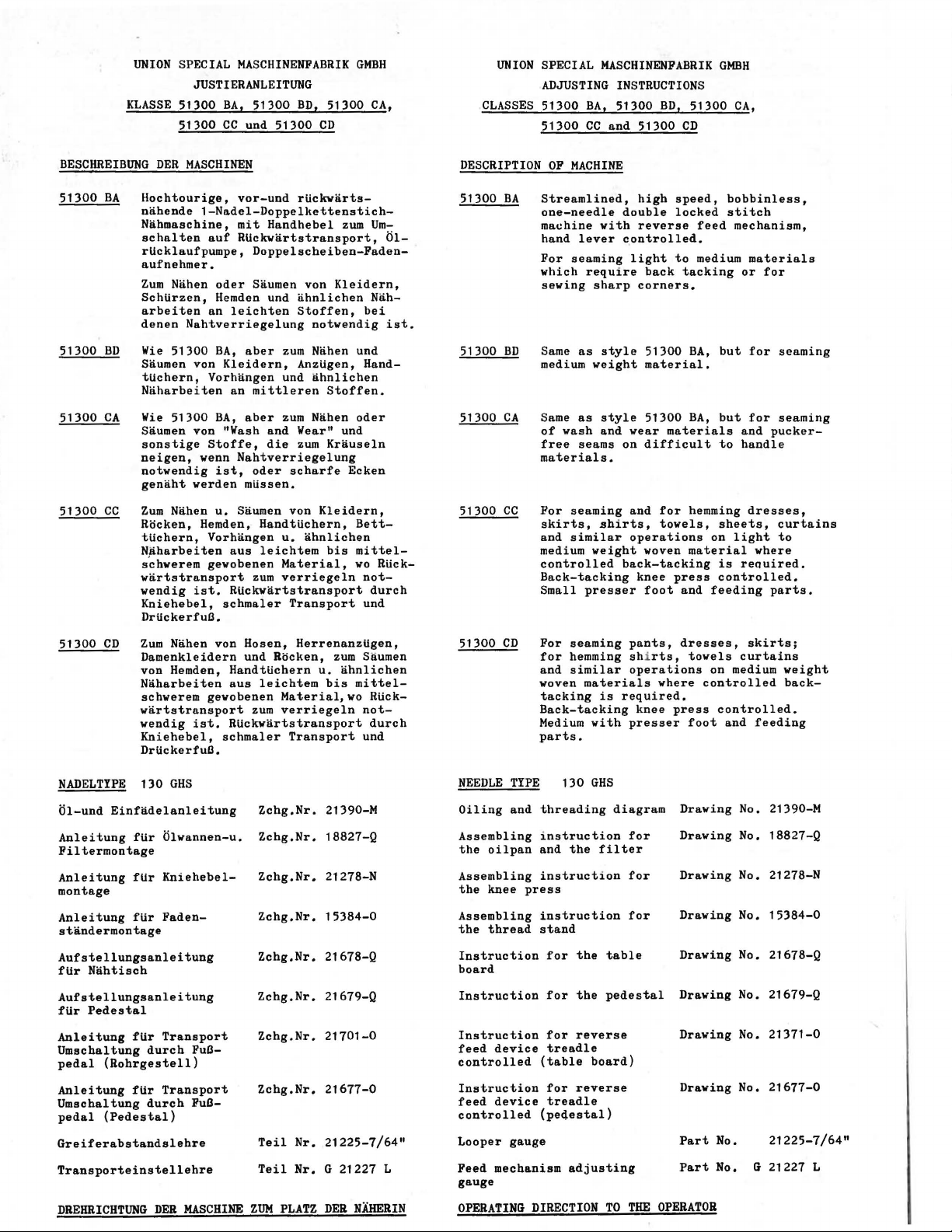
BESCHREIBUNG
51300
BA
Hochtourige,
nnhende
Nahmaschine,
schalten
rUcklaufpumpe,
aufnehmer.
Zum
SchUrzen,
arbeiten
denen
51300
BD
Wie
Saumen von
tUchern,
Naharbeiten
51300
CA
Wie
Saumen von "Wash
sonstige
neigen,
notwendig
genaht
51300
CC
Zum
Rocken,
tUchern,
Nliharbeiten
s~hwerem
wartstransport
wendig
Kniehebel,
DrtickerfuLl.
51300
CD
Zum
Damenkleidern
von Hemden,
Naharbeiten
schwerem gewobenen
wartstransport
wendig
Kniehebel,
DrtickerfuLl.
DER
MASCHINEN
vor-und
1-Nadel-Doppelkettenstich-
mit
auf
RUckwartstransport,
Doppelscheiben-Faden-
Nahen
oder
Saumen von
Hemden und
an
leichten
Nahtverriegelung
51300
BA,
aber
Kleidern,
Vorhangen
an
mittleren
51300
BA,
aber
Stoffe,
wenn
Nahtverriegelung
ist,
werden
Nahen
Hemden,
ist.
Nahen von
ist.
oder
mUssen.
u.
Saumen von
Vorhangen
gewobenen
HandtUchern,
aus
leichtem
zum
RUckwartstransport
schmaler
Rosen,
und
HandtUchern
aus
leichtem
zum
Rtickwartstransport
schmaler
rUckwarts-
Handhebel
ahnlichen
Stoffen,
notwendig
zum
Nahen und
AnzUgen,
und
ahnlichen
Stoffen.
zum
Nahen
and
Wear" und
die
zum
Krauseln
scharfe
Kleidern,
u.
ahnlichen
bis
Material,
verriegeln
Transport
HerrenanzUgen,
Rocken,
u.
bis
Material,wo
verriegeln
Transport
zum
Um-
Kleidern,
Nah-
bei
Hand-
oder
Ecken
Bettmittel-
wo
RUck-
not-
durch
und
zum
Saumen
ahnlichen
mittel-
Rtick-
not-
durch
und
01-
ist.
DESCRIPTION
51300
BA
51300
BD
51300
CA
51300
CC
51300
CD
OF
MACHINE
Streamlined,
one-needle
machine
hand
For
which
sewing
Same
medium
Same
of
free
materials.
For
skirts,
and
medium
controlled
Back-tacking
Small
For
for
and
woven
tacking
Back-tacking
Medium
parts.
with
lever
seaming
require
sharp
as
style
weight
as
style
wash
and
seams on
seaming
shirts,
similar
weight
presser
seaming
hemming shi
similar
materials
is
with
high
double
controlled.
back-tacking
required.
speed,
locked
reverse
light
to
back
tacking
corners.
51300
material.
51300
wear
materials
difficult
and
for
towels,
operations
woven
knee
press
foot
and
pants,
operations
presser
rts,
knee
dresses,
where
press
BA,
BA,
hemming
material
towels
foot
bobbinless,
stitch
feed
mechanism,
medium
or
but
but
and
to
handle
sheets,
on
light
is
reQuired.
controlled.
feeding
curtains
on medium
controlled
controlled.
and
materials
for
for
seaming
for
seaming
pucker-
dresses,
curtains
to
where
parts.
skirts;
weight
back-
feeding
NADELTYPE
Ol-und
Anleitung
Filtermontage
Anleitung
montage
Anleitung
standermontage
Aufstellungsanleitung
ftir
Nahtisch
Aufstellungsanleitung
ftir
Pedestal
Anleitung
Umschaltung
pedal
Anleitung
Umschaltung
pedal
Greiferabstandslehre
Transporteinstellehre
DREHRICHTUNG
130
GHS
Einfadelanleitung
fUr
Olwannen-u.
fUr
Kniehebel-
ftir
Faden-
ftir
Transport
durch
(Rohrgestell)
ftir
Transport
durch
(Pedestal)
DER
FuLl-
FuLl-
MASCHINE
Zchg.Nr.
Zchg.Nr.
Zchg.Nr.
Zchg.Nr.
Zchg.Nr.
Zchg.Nr.
Zchg.Nr.
Zchg.Nr.
Teil
Teil
ZUM
PLATZ
21390-M
18827-Q
21278-N
15384-0
21678-Q
21679-Q
21701-0
21677-0
Nr.
21225-7/64"
G 21227
Nr.
DER
L
NAHERIN
NEEDLE
Oiling
Assembling
the
Assembling
the
Assembling
the
Instruction
board
Instruction
Instruction
feed
controlled
Instruction
feed
controlled
Looper
Feed
gauge
OPERATING
TYPE
and
oilpan
knee
press
thread
device
device
gauge
mechanism
DIRECTION
130
threading
instruction
and
instruction
instruction
stand
for
for
for
treadle
(table
for
treadle
(pe4estal)
GHS
diagram
the
filter
the
table
the
pedestal
reverse
board)
reverse
adjusting
TO
for
for
for
THE
Drawing
Drawing
Drawing
Drawing
Drawing
Drawing
Drawing
Drawing No.
Part
Part
OPERATOR
No.
21390-M
No. 18827-Q
No. 21278-N
No.
15384-0
No.
21678-Q
No. 21679-Q
No.
21371-0
21677-0
No.
No. G 21227 L
21225-7/64"
Page 6
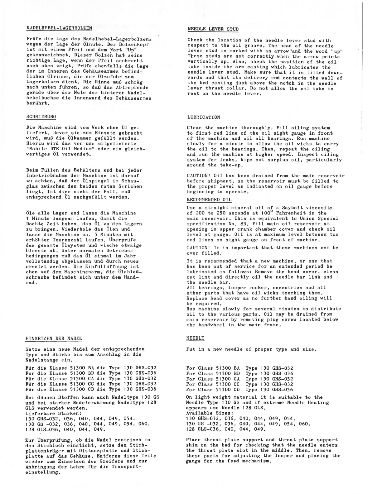
NADELHEBEL-LAGERBOLZEN
PrUfe
die
Lage
des
wegen
der
mit
oben
im
unten
Lage
einem
Lage,
zeigt.
Inneren
fUhren,
tiber
ist
gekennzeichnet.
richtige
nach
der
lichen Olrinne,
Lagerbolzen
nach
gerade
hebelbuchse
berlihrt.
dient.
der
die
Nadelhebel-Lagerbolzens
der
Olnute.
Pfeil
und dem
Dieser
wenn
der
PrUfe
des
Gehausearmes
die
der
Die
so
Nute
der
Innenwand
Bolzen
Pfeil
ebenfalls
Olzufuhr
Rinne
daO
das
hinteren
des
Der
Bolzenkopf
Wort
"Up"
hat
seine
senkrecht
die
befind
zum
muO
schrag
Abtropfende
Nadel-
Gehliusearmes
Lage
-
NEEDLE
Check
the
respect
lever
stud
These
studs
vertically
tube
inside
needle
wards
and
the
bed
lever
thrust
rest
on
LEVER
location
to
the
up.
lever
that
casting
the
STUD
is
marked
are
the
stud.
collar.
needle
oil
set
Also,
arm
its
just
of
the
groove.
with
correctly
check
casting
Make
sure
delivery
above
Do
not
lever.
needle
The
an
arrow
the
which
that
end
the
allow
lever
head
when
position
lubricates
it
contacts
notch
the
of
'anCI.
the
is
in
stud
the
the
arrow
of
tilted
the
oil
the
tube
with
needle
word
points
the
the
wall
needle
"up"
oil
down-
of
to
SCIINIERUNG
Die
Maschine
liefert.
wird,
Hierzu
"Mobile
wertiges
Beim
Inbetriebnahme
zu
glas
liegt.
entsprechend
Ole
1
Ninute
Dochte
zu
lasse
erhohter
das
Olreste
bedingungen
vollstandig
ersetzt
oben
schraube
rad.
muO
wird
DTE
FUllen
achten,
zwischen
Ist
alle
Zeit
bringen.
die
gesamte
ab.
werden.
auf
llevor
die
01
Lager
langsum
Maschine
Tourenzahl
dem
befindet
wird
vom
sie
zum
Olkammer
das
von
Oil
Medium"
verwendet.
des
Behalters
der
daO
dies
haben,
Wiederhole
Olsystem
Unter
muO
abgelassen
Naschine
der
Olspiegel
den
heiden
nicht
01
nachgefUllt
und
lasse
laufen,
dns
ca. 5 Minuten
laufen.
normalen
das
01
Die
Maschinenarm,
Einflilloffnung ist
sich
Werk
ohne
Einsatz
gefUllt
uns mitgelieferte
oder
roten
der
die
damit
01
das
und
wische
einmal
und
unter
01
gebracht
werden.
ein
und
bei
ist
darauf
im
Schau-
Strichen
Fall,
muO
werden.
Maschine
die
zu
den
Olen
und
Uberprlife
etwaige
Betriebs-
im
durch
die OlablaO-
dem
ge
-
gleich
jeder
Lagern
mit
Jahr
neues
Hand-
LUBRICATION
Clean
the
to
first
of
the
-
slowly
the
and
system
around
CAUTION! Oil
before
the
beginning
RECOMNENDED
Use a
of 200
ma
in
s
pecification
opening
level
red
C
AUTION1 It
over
It
is
has
lubricated
out
the nee
All
other
Replace
be
required.
Run
oil
main
the hnndwheel
machine
red
machine
for a minute
oil
to
run
proper
lines
been
lint
bearings,
machine
to
the
the
for
leaks.
the
take-up.
shipment,
level
to
s
traight
to
250
reservoir.
in
upper
at gauge.
on
filled.
recommended
out
as
and
dle
bar.
parts
head
the various
reservoir
line
and
bearings.
machine
has
been
so
as
operate.
OIL
mineral
seconds
This
No.
crank
Oil
sight
is
important
of
service
follows:
directly
looper
that
have
cover
slowly
by
in
the
thoroughly.
of
the
oil
oil
all
to
allow
Then,
at
higher
Wipe
out
drained
the
reservoir
indicated
oil
at
100°
is
equivalent
83.
Fill
chamber
is
at
gauge
on
that
that
a new
for
Remove
oil
rocke
oil
no
several
main
wicks
further
Oil
frame.
as
for
parts.
removing
Fill
sight
bearings.
the
oil
repeat
speed.
surplus
from
must
on
oil
of a Saybolt
Fahrenheit
main
oil
cover
maximum
the
r ,
plug
front
these
machine,
an
extended
the
needle
eccentrics
touching
hand
minutes
may
screw
level
of
head
be
oiling
gauge
Run
wicks
the
Inspect
oil,
the
main
be
gauge
viscosity
to
Union
reservoir
and
between
machine.
machines
or
period
cover,
bar
and
oiling
to
drained
located
system
in
front
machine
to
carry
oiling
oiling
particularly
reservoir
filled
before
in
the
Special
at
check
oil
two
not
one
that
be
clean
link
and
all
them.
will
distribute
from
below
to
be
N
EINSETZEN
Setze
eine
Type und
Nadelstange
FUr
FUr
FUr
FUr
FUr
Bei
und
GLS
Lieferbare
130
130
128
Zur
das
plattentrager
platte
wieder
Anbringung
einstellung.
Klasse
die
die
Klasse
Klasse
die
Klasse
die
Klasse
die
dUnnen
bei
starker
verwendet
GHS-032,
GS
-032,
GLS-036,
UberprUfung,
Stichloch
auf
zum
DER
NADEL
neue
Nadel
Stii.rke
bis
ein.
51300
51300
51300
51300
51300
Stoffen
Nadelerwarmung
werden.
Stlirken:
036, 040,
036, 040,
040, 044, 049.
ob
einsticht,
mit
das
Gehii.use.
Einsetzen
der
Lehre
der
entsprechenden
zum
Anschlag
BA
die
llD
die
CA
die
cc
die
CD
die
kann
auch
044, 049,
044,
die
Nadel
des
fiir
setze
Entferne
Greifers
die
Distanzplatte
in
Type
130
Type
130
Type
130
130
Type
Type
130
Nadeltype
Nadeltype
054.
049,
054,
zentrisch
den
und
diese
Transport-
die
Stich-
Stich-
und
GHS-032
GHS-036
GHS-032
GHS-032
GHS-036
130
128
060.
in
Teile
zur
GS
EEDLE
P
ut
in
a new
For
Class
Class
For
Class
For
For
Class
Class
For
On
light
Needle
appears
Available
130
130
128
Place
shim
the
these parts
gauge
Type
use
GHS-032,
GS
-032,
GLS-036,
throat
on
the
throat
for
needle
51300
51300
51300
51300
51300
weight
130
Needle
Sizes:
036, 040, 044, 049,
036, 040, 044,
040, 044,
plate
bed
plate
for
the
BA
BD
CA
cc
CD
material
GS
for
slot
adjusting
feed
of
proper
Type
130
Type
130
Type
130
Type
130
Type
130
it
and
i f
GLS.
049.
checking
in
the
extreme
and
the
128
support
mechanism.
type
GHS-032
GHS-036
GHS-032
GHS-032
GHS-036
i s
suitable
049,
throat
that
middle.
looper
and
size.
Needle
054.
054, 060.
plate
the
needle
Then,
and
to
the
Heating
support
remove
placing
enters
the
Page 7
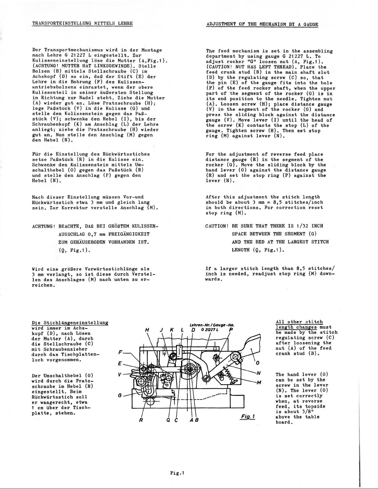
TRANSPORTEINSTELLUNG
Der
Transportmechnnismus
nnch
Lehre
G 21227 L
Kulisseneinstellung
(ACHTUNG!
Bolzen
Achskopf
Lehre
nntriebsbolzens
Kulissenteil
in
Richtung
(A}
lege
stelle
stUck
Schraubenkopf
nnliegt;
gut
den
PUr
setze
Schwenke
schalthebel
und
Hebel
Nach
RUckwartsstich
sein.
(B)
(D)
in
die
wieder
PaOstUck
den
(V);
ziehe
an.
Nun
Hebel
die
Einstellung
PaOstUck
den
stelle
(N}.
dieser
Zur
MUTTER
HAT
mittels
so
ein,
Bohrung
einrastet,
in
seiner
zur
Nadel
gut
nn.
(V}
in
Kulissenstein
schwenke
(K}
am
die
stelle
(N}.
(R)
Kulissenstein
(0)
gegen
den
Anschlag
Einstellung
etwa 3 mm
Korrektur
Stellschraube
Lose
Prntzschraube
den
in
mTTELS
wird
LEHRE
in
eingestellt.
lose
die
Mutter
LINKSGEWINDE}.
dnO
der
des
Stift
Kulissen-
(F)
wenn
nuOersten
steht.
Ziehe
Prntzschraube
die
Kulisse
gegen
den
Hebel
Anschlag
dns
(I},
(L}
Anschlag
des
RUckwnrtsstiches
die
Kulisse
mittels
das
PaOstUck
(P}
gegen
mUssen
verstelle
und
Vor-und
gleich
Anschlag
der
Zur
(A,Pig.1}.
Stelle
(C)
(E)
der
obere
Stellung
die
(G) und
PaObis
der
(H)
(M}
gegen
ein.
Um(R}
den
lang
Montage
im
der
Mutter
(H);
der
Lehre
wieder
(M}.
ADJUSTMENT
The
feed
mechanism
department
adjust
rocker
(CAUTION!
feed
crank
(D) by
the
(F)
part
its
(A}.
(V}
press
gauge
the
gauge.
ring
For
distance
rocker
hand
(R}
lever
After
should
in
stop
pin
of
of
end
Loosen
in
screw
(M}
the
lever
and
both
ring
the
(E)
the
the
position
the
the
(V}.
Tighten
against
adjustment
gauge
(G).
set
(N}.
this
be
directions.
OF
THE
MECHANISM
by
using
"G"
HAS
loosen
LEFT
(B)
NUT
stud
regulating
of
the
feed
rocker
segment
to
screw
(H);
segment
sliding
Move
(K}
block
lever
contacts
screw
lever
of
(R}
Move
(0}
the
in
the
against
stop
adjustment
about 3 mm
(M}.
is
set
gauge
in
screw
gauge
of
the
of
the
(I}
(H).
reverse
the
sliding
ring
the
= 815
For
BY A GAUGE
in
the
G 21227
nut
(A,
THREAD}.
the
main
(C)
fits
shaft,
the
rocker
needle.
place
distance
rocker
against
until
the
stop
Then
(N}.
segment
block
the
distance
(P}
stitch
stitches/inch
correct1on
assembling
L.
Pig.1}.
Place
shaft
so,
into
when
(G)
Tighten
(G)
the
the
(L}
set
feed
of
against
length
To
the
slot
that
the
hole
the
upper
is
gauge
and
distance
head
of
the
stop
place
the
by
the
gauge
the
reset
in
nut
of
ACHTUNG!
BEACHTE,
AUSSCHLAG
ZUM
GEHAUSEBODEN
(Q,
Fig.1}.
Wird
eine
verlangt,
des
Anschlages
groOere
3
len
mm
reichen.
Die
Stichlangeneinstellung
wird
immer
kopf
der
Mutter
die
Stellschraube
mit
Schraubenzieher
durch
loch
Der
Umschalthebel
wird
schraube
eingestellt.
im
(D),
nach
(A},
das
Tischplatten-
vorgenommen.
durch
die
im
Hebel
Beim
RUckwartsstich
er
waagerecht,
1
em
tiber
platte,
der
stehen.
DAB
BEl
0,7
mm
Vorwnrtsstichlange
so
ist
diese
(M}
nach
Achs-
Losen
durch
(C)
(0}
Pratz-
(N}
soll
etwa
Tisch-
GROBTEM
KULISSENFREIGANGIGKEIT
VORHANDEN
IST.
als
durch
Verstel-
unten
zu
er-
H
J K L D G
l..llhnn-Nr.l
CAUTION!
If a larger
inch
is
needed,
wards.
Gaug•
21221
-No.
L p
BE
SURE
SPACE
AND
THE
LENGTH
stitch
THAT
BETWEEN
BED
AT
(Q,
Pig.1}.
length
readjust
THERE
THE
SEGMENT
THE
than
stop
All
length
be made
regulating
after
nut
crank
The
can
screw
(N}. The
is
set
when,
feed,
is
about
above
board.
IS
1/32
LARGEST
8,5
ring
other
st i
changes
by
loosening
(A}
of
stud
hand
lever
be
set
in
the
lever
correctly
at
reverse
its
topside
3/8"
the
table
INCH
(G)
STITCH
stitches/
(M}
down-
tch
must
the
stitch
screw
the
the
feed
(B).
(0}
by
the
lever
(0}
(C)
Fig.1
Page 8
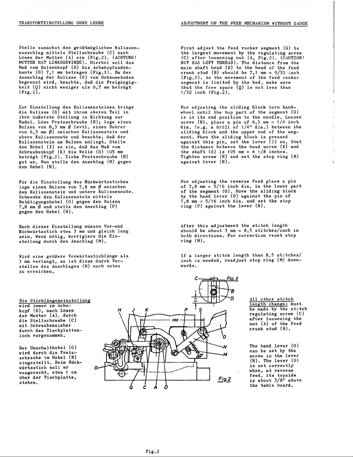
TRANSPORTEINSTELLUNG
OHNE
LEHRE
ADJUSTMENT
OF
THE
FEED
MECHANISM
WITHOUT
GAUGE
Stelle
ausschlag
Losen
MUTTER
MaO
kante
Ausschlag
begrenzt
keit
(Pig.2).
Zur
die
ihre
Nadel.
Bolzen
von
obere
Kulissenstein
den
Schraubenkopf
betragt
gut
den
PUr
lege
den
Schwenke
Betatigungshebel
7,8
gegen
zunnchst
mittels
der
Mutter
HAT
vom
Einstellung
Kulisse
6,3
Hebel
an.
Hebel
die
Kulissenstein
mm ¢ und
LINKSGEWINDE).
Bolzenkopf
(D)
7,1
der
wird,
(Q)
nicht
nuOerste
einen
(G)
Lose
Pratzschraube
von 6 3
mm
¢}
Kulissennute
(I)
(Pig.2).
Nun
stelle
(N).
Einstellung
Bolzen
den
den
Hebel
den
groOtmoglichen
Stellschraube
(A)
ein
(B)
mm
betragen
Kulisse
beachte,
weniger
des
Stellung
mm ¢ (evtl.
zwischen
am
so
(K)
Kulissenstein
stelle
(G)
Kulissensteines
mit
ihrem
und
Bolzen
ein,
daO
bis
Welle
Ziehe
den
des
von
7,8
und
untere
(0)
gegen
den
(N).
(Fig.2).
bis
daO
als
in
Kulissenstein
beachte,
anliegt.
Pratzschraube
Anschlag
Rtickwartsstiches
Anschlag
(C)
Hierbei
AchskopfauOen(Fig.3).
vom
die
0,7
oberen
Richtung
(H);
einen
das
mm
mittels
den
(ACHTUNG!
soll
Gehnuseboden
Freigangig-
mm
betrllgt
Teil
lege
Bohrer
daO
Stelle
MaO
vom
(S)
105
(M)
¢zwischen
Kulissennute.
Bolzen
(P)
Kulissen-
nach
das
Da
der
bringe
in
zur
einen
und
der
mm
(H)
gegen
First
the
largest
(C)
after
NUT
HAS
main
crank
(Fig.3).
segment
that
1/32
For
adjusting
wheel
is
i n
screw
dia.
sliding
ment.
against
the
distance
the
shaft
Tighten
against
For
adjusting
of
7,8
of
the
by
the
7,8
mm = 5/16
ring
adjust
shaft
stud
the
inch
until
its
(H),
(e.g. a drill
When
(P)
the
movement by
loosening
LEFT
THREAD).
head
(B)
As
the
is
limited
free
space
(Pig.2).
the
the
end
position
place a pin
block
and
the
this
pin,
between
(S)
is
screw
(H)
lever
(N).
mm = 5/16
segment
hand
the
lever
inch
against
should
sliding
(G).
feed
rocker
nut
The
(D)
to
be
movement
by
the
(Q)
sliding
top
part
of
1/4"
the
upper
set
the
the
105
mm
and
set
reverse
inch
dia.
Move
(0)
against
dia.
the
lever
segment
the
regulating
(A,
Pig.2).
distance
the
head
7,1
mm = 9/32 inch
of
the
bed,
is
not
block
of
the
to
the
of
6,3
dia.}
end
block
is
lever
head
= 4
1/8
the
feed
in
the
sliding
and
set
(N).
(G)
(CAUTION!
from
of
the
feed
rocker
make
sure
less
than
turn
hand-
segment
needle.
mm = 1/4
screw
stop
place a pin
the
the
between
of
the
pressed
(I)
so,
(K)
inches.
ring
lower
pin
the
stop
Loosen
block
of
to
screw
the
feed
(G)
inch
the
seg-
that
and
(M)
part
Nach
dieser
Rtickwartsstich
sein.
stellung
Wird
eine
3
mm
verlangt,
stellen
zu
erreichen.
Die
Stichlangeneinstellung
wird
immer i m
kopf
(D),
der
Mutter
die
Stellschraube
mit
Schraubenzieher
durch
loch
vorgenommen,
Umschalthebel
Der
wird
durch
schraube
eingestellt.
wartsstich
waagerecht,
tiber
der
stehen.
Wenn
notig,
durch
groCere
des
nach
das
Tischplatten-
im
Tischplatte,
Einstellung
Anschlages
(A),
die
Hebel
soll
etwa 1 em
etwa 3 mm
korrigiere
den
Anschlag
Vorwartsstichlange
so
ist
diese
Achs-
Losen
durch
(C)
(0)
Pratz-
(N)
Beim Rlick-
er
mtissen
und
(M)
nach
gleich
die
(M).
durch
G
Vor-und
lang
Ein-
Ver-
unten
als
After
this
should
both
ring
If a larger
inch
wards,
be
directions,
(M).
is
needed,
adjustment
about 3 mm = 8,5
stitch
For
correction
length
readjust
the
stitch
stitches/inch
than
8,5 sti
stop
ring
All
other
length
be
made by
regulating
after
loosening
nut
(A)
crank
stud
The
hand
can
be
screw
in
(N).
The
is
set
when,
at
feed,
its
is
about
the
table
length
reset
changes must
of
lever
set
the
lever
correctly
reverse
3/8"
stop
tches/
(M)
down-
stitch
the sti
screw
the
(B).
by
the
lever
topside
above
board.
in
(C)
the
feed
(0)
(0)
tch
Fig.2
Page 9
EINSTELLEN
Setze
den
und
auf
gut
zwischen
und
die
Zum
die
gelost
der
verden
ist
lager
jeder
nicht
Greifer
beachte,
die
Flache
angezogen
der
Nadelmitte
Greifereinstellehre
Einstellen
beiden
und
Greiferabstand
die
darauf
rechts
Stellung
klemmen.
DES
GREIFERS
daO
des
ist,
rechten
auf
des
Muttern
die
Schubstange
Muttern
zu
achten,
und
frei
in
den
die
links
Greiferhebel
Befestigungsschraube
Greifers
Stelle
Greiferendstellung
2,8
Greiferabstandes
auf
richtig
gut
bewPgen
drUckt
den
mm
ein,
21225-7/64".
der
Schubstange
verdreht.
eingestellt,
angezogen,
daa
sich
der
Schubst~nge
konnen
und
Abstand
BenUtze
Dabei
die
Kugelund
ein
verden
Ist
in
LOOPER
.
Insert
Notice
flat.
measurement
needle
the
stroke,
inch.
used
ment,
For
tvo
After
nuts
rod
positions.
ADJUSTMENT
the
that
The
to
looper
This
Looper
advantageously
the
looper
nuts
the
securely.
ball
looper
the
looper
from
the
is
measurement
gauge
on
the
right
joints
screw
gauge
the
point
at
the
gauge
looper
gauge
Notice
have
in
the
rests
centerline
of
right
No.
21225-7/64
in
making
adjustment
connecting
is
that
clearance
looper
on
represents
the
looper
end
should
this
set,
tighten
the
rocker.
the
looper
the
of
the
when
of
the
be
7/64
can
be
adjust-
loosen
rod.
connecting
in
the
all
the
GREIFERAUSWEICHBEWEGUNG
Wenn
sich
der
soll
seine
an
der
ohne
papierstdrke).
durch
seitenweghebel
achse.
wieder
SYNCHRONISIERUNG
Die
der
Reparaturzwecke
wie
Drehe
bis
nach
stimmt,
ohrs
das
bis
links
mitte
richtig
ohrs
wie
0,13
vom
Drehen
groOer
verstelle
Greiferantriebsachse
buchsen
so
Buchsen
RUckseite
sie
Losen
Nachher
gut
Greifer-und
Montage
folgt:
das
die
links
zur
Handrad
sich
bevegt
Ubereinstimmt.
zu
vorher.
mm
Nadelohr
des
als
nach
verstelle
nach
Greifer
Spitze
jedoch
Die
der
und Schwenken
mua
angezogen
synchronisiert,
Handrad
Greiferspitze
mit
Stelle
ist,
der
ist
der
die
Greiferspitze
in
umgekehrter
die
Greiferspitze
und
mua
Greiferspitze
Ein
zulassig.
zur
Handrades
beim
den
Greiferantriebshebel
hinten.
den
vorn.
nach
so
dicht
der
Nadel
zu
berUhren
Einstellung
Pratzschraube
die
Pratzschraube
verden.
DES
GREIFERS
Nadelbevegung
prUfe
die
in
Arbeitsrichtung,
bei
Nadelmitte
Hohenlage
fest.
vieder
Wenn
die
Hohenlage
kleiner
Ist
Greiferspitze
in
umgekehrten
und
Ist
Hebel
mit
links
bewegt,
wie
moglich
vorbeigehen,
{Zeitungs-
erfolgt
im
Greifer-
der
Greifer-
vurde
FUr
Synchronisation
ihrer
Bevegung
Uberein-
des
Nadel-
Dann
Richtung,
wieder
mit
die
dieselbe
Unterschied
der
Arbeitsrichtung
den
er
Achse und
drehe
nach
der ·Nadel-
Bevegung
des
Nadel-
sein
Abstand
beim
Drehen,
kleiner,
mi t
Lager-
in
von
so
LOOPER
When
the
point
should
as
close
LOOPER
The
synchronization
needle
Without
checked
Turn
the
until
the
and
is
height
respect
the
pulley
looper
is
even
are
synchronous,
the
needle
point
will
0.05
inch
from
the
of
the
is
turned
the
looper
looper
the
move
bushings
drive
rear,
the
AVOID
MOTION
looper
as
SYNCHRONIZATION
is
gauges
as
pulley
even
of
to
point
with
eye
looper
lever
to
pass
possible
set
by
follows:
looper
with
the
eye
the
in
reverse
moves
the
with
be
the
is
allowable.
of
is
in
operating
drive
shaft
If
the
the
moves
the
without
of
gauges
the
synchronization
in
operating
point
the
needle.
of
the
looper
again
needle.
the
height
respect
same, A variation
the
needle
longest
lever
and
distance
rocker,
front.
to
the
rear
of
the
looper
at
the
moves
needle
point,
direction
to
If
to
the
If
the
to
when
direction,
rocker
its
bushings
is
the
shaft
left,
the
needle
contacting.
and
factory.
direction
to
the
Note
the
with
then
turn
until
the
left
the
motions
of
the
looper
distance
the
point
the
pulley
move
with
smallest
and
its
can
left
eye
of
the
to
the
be
the
and
of
its
EINSTELLEN
Stelle
die
Greiferspitze
spitze
der
riegeln
venn
die
Nadelohroberkante
bei
linken
konnen
die
Nadel
DER
NADELSTANGE
Nadelstange
ist,
ihrer
Nadelseite
wenn
Bewegung
Fehlstiche
zu
tief
so
hoch
0,4
sich
deckt.
eingestellt
ein,
mm
unter
die
links
Beim
Greifer-
Ver-
nach
~ntstehen,
daO
der
mit
ist.
NEEDLE
Set
the
needle
the
looper,
to
the
needle.
occur
BAR
needle
eye
left
When
if
the
is
when
is
tacking
needle
bar
less
even
so
than
point
with
is
that
of
skip
set
1/64
looper
left
stitches
the
too
top
inch
side
lov.
of
below
moving
of
may
the
the
Page 10
HIL~'SGREil~EREINST
Stelle
schlitz
iuOersten
Mitte
so
beim
0,5
dnrf
Um
einzustellcn,
neben
vorhandene
Schraubenzieher
im
rechten
untere
Kurbelachse,
flache
Deckel
Wenn
greifer
wird,
laOt
bis
dem
des
durchgedreht
oberen
des
Einstellung
Hilfsgreiferantrieb
werden,
damit
des
achse
achse
schrauben
Die
muO
daO
Der
halb
Der
von
hoher
VORDERER
Stelle
Oberkante
oder
geringen
gerade
zur
Verriegeln
Nadelanschlag
und
tief
die
hinteren
TRANSPORTEURSTELLUNG
Stelle
Zahnspitzen
parallel
St1chplattenoberflache
Halteschraube
hoch,
bleibt.
PrUfe
kante
porteurunterseite,
zusammenkommen.
dieselbe
greiferhaken
notig,
dem
keit
den Hilfsgreiferarm
so
linken
Nadel
~cit
vor,oder zurUck,
Vorbeigehen
bis
0,8
die
Nadel
den
Hilfsgreiferantrieb
dem
Greiferantriebshebel
angetriebenen
Achse.
Totlage
der
weist.
der
Schraubenradantrieb
richtig
den
dlbehlilterdeckel
sich
der
auf
das
Behnlterdeckel
Deckels
Totlage
Hilfsgreiferantriebes
wobei
sich
getriebenen
nicht
nicht
eingesetzt
Zeiteinstellung
dann
korrekt
diese
Zeiteinstellung
Hilfsgreiferhaken
der
Greiferoberkante
Hilfsgreifer
Distanzblechen
oder
NADELANSCHLAG
den
auf
etwas
Abstand
berUhren,
Nadel
kommt.
der
hintere
wie
moglich
Beschreibung
Nadelanschlages,
den
zur
daO
diese
die
Freigangigke
des
Hilfsgreiferhakens und
sein,
andere
Hilfsgreiferlagerbock,
zu
schaffen.
I>L
ein,
daO
Stellung
cntfernt
an
mm
Freigangigkeit
nicht
entferne
Schraube,
ein
Schraubenrad
Stelle
und
bis
die
Kurbel
beim
niedriger
vorderen
darUber.
auftreten,
Transporteur
auf
angebracht
ganze
treibende
muO
die
werden,
ist
kann
der
man
vorsichtig
Knmmen
Schraubenrades
verstellt.
verstellt
sein. fberzeuge
kann
die
Hohe
zur
wenn
NadelbrUche
nicht
Nadelanschlag
steht. Hie
tiber
bei
hochstem
und
3/
unter
Einstellung
Sie
wie
und
Oberkante
die
Zwischenscheibe
LUNG
in
d i e
seinem
Hakenspitze
0,1"=2,5
is
t.
Stelle
daO
der
bcrUhren.
fUhre
und
die
drehe
Zeitmarke
die
Hilfsgreiferantrieb,
Schraubenrad,
wegnehmen.
Maschine
bis
und
obere
dann wieder
ha
und
des
muO
durch
unter
gestellt
Nadelanschlag
Der
Nadel
die
wenn
so
die Einstellung
64"=1,2
dem
i t
wo
sie
sollte
zwischen
die
RUckseite
hat.
zeitlich
die
gleich
in
das
lose
die
auf
Nadelstange
die
senkrechte
Zeitmarke
fUr
ist
zu
entfernen,
Zum
vorher
die
Nadel
sich
die
decken.
Deckel
vorgehen
des
treibenden
Wenn s
ich
t,
konnen
festgezogen
llilfsgreiferantriebes
wirklich
um
0,25
frei
Zwischenlegen
seinen
werden.
der
Greiferspitze
Anschlag
haben
Greiferspitze
werden
der
hoch
wie
nicht
rzu
so
ein,
Transporthub
mm
si
tiber
d.
Stelle
Transporteur
erhalten
zwischen
am
dichtesten
ungefahr
dem
Greifer.
urn
Frei~·ngig
FUhrungs-
in
mm
von
den
Lagerbock
Hakenspitze
der
Nadel
Der
richtig
rechts
im
Gehiuse
Loch
Schrauben
der
senkin
an
der
Stirn-
am
oberen
den
Hilfs-
und
es
notig
mit
Einsetzen
so
weit
in
der
Zeitmarken
In
dieser
mit
dem
eingebaut
muO,
die
vorbeigehen.
vordere
siehe
und
Kurbel-
die
Kurbel-
die
Deckel-
werden.
dich
aber,
stimmt,
mm
ober-
Lagerbock
mit
seiner
knnn
einen
oder
diese
beim
moglich
so
auch
des
daO
d1e
der
die
so
Ober-
Trans-
Hilfs-
Wenn
unter
ihrer
Hnken
einen
die
RETAINING FINGER DRIVE
Adjust
slot
travel
line
or
point,
has
No
needle.
To
plug
the
and
vertical
bottom
crank
strap)
of
the
If
and
chamber
will
main
replaced,
over
stroke,
positioned
The
as
careful
and
shaft
not
and
be
is
The
the
retainer
necessary
bracket.
FRONT
Set
that
higher
the
needle
needle,
back
high
as
rear
FEED DOG ADJUSTMENT
Set
teeth
above
of
under
setting.
Check
hook
approach.
the
and
change
to
the
so
to
of
forth
when
1/32
part
time
the
screw
looper
loosen
of
shaft
until
the
vertical
timing
the
retainer
if
it
top
lift
shaft
so
that
and
top
cover
above
that,
the
driven
does
turn,
tightened
correct.
correct.
retainer
looper
NEEDLE
the
front
its
than
guarding
as
Needle
tacking
as
possible
possible.
needle
the
feed
are
the
travel,
the
clearance
and
same
the
top
the
get
clearance.
retaining
that
the
needle.
in
its
passing
inch
of
the
retainer
in
drive
screws
shaft.
the
by
mark
becomes
cover,
off
gear,
the
the
so
can
not
the
Check
by
can
by
top
the
the
guard,
parallel
throat
Adjust
feed
bottom
This
as
that
of
shims
the
hook
left
is
Set
the
adjustment
the
clearance
hook
should
casting
lever,
in
Set
the
stroke
hand
timing
crank
on
gear
necessary
When
machine
needle
retainer
the
timing
be
gear
turn.
cover
the
the
least
raised
looper
looper
breakage
the
and
paragraph
so
plate
the
dog,
between
of
clearance
between
the
under
{gripping
the
the
the
the
the
mesh
screws
shims
front
that
with
to
feed
looper.
the
with
the
with
then
when
and
hook should
at
be
using
GUARD
needle
surface
surface
if
See
dog
arm
in
point
0.01
pivot
back
back
drive
just
insert
the
driven
needle
and
turn
mark
check
top
drive
entire
top
the
cover
should
is
drive
marks
retainer
put
in
main
together,
If
the
retainer
timing
clear
.010
or
lowered
under
guard
is
as
point,
just
contacts
point
will
guard
the
rear
the
and
at
highest
supporting
maintain
top
dog
should
the
the
or
at
inch
bracket
so
that
of
of
ever
remove
to
the
the
the
on
lines
cover.
is
located
to
retainer
cover
first
at
the
are
place
shaft
crank
can
be
to
inch.
high
high
and
comes
occur
guard
for
tips
3/64
of
at
retainer
If
necessary,
pivot
out
of
its
furthest
from
the
the
the
contact
access
right
screw
gear
bar
at
vertical
crank
the
up
remove
except
is
to
be
top
should
in
drive
being
drive
the
shaft
inserted
timing
be
sure
the
top
The
as
the
pivot
enough
or
slightly
so
the
up
when
is
not
setting
of
inch
point
screw,
this
retainer
closest
be
about
bracket
its
center
back
hook
needle,
ne
dle.
driver
on
the
face
with
properly
the
drive
be
turned
of
be
line.
set
crank
will
of
so
that
to
the
as
as
low
the
hook
the
of
the
oil
the
its
gear
does
it
Page 11
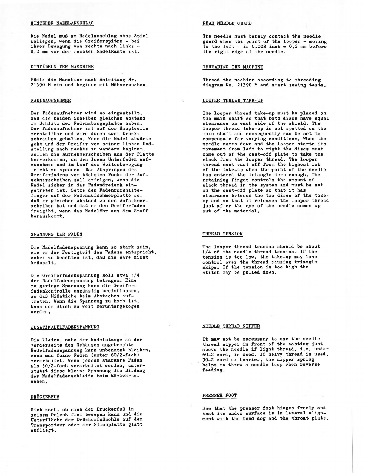
HINTERER
Die
Nadel
anliegen,
ihrer
Devegung von
0,2
mm
NADELANSCHLAG
muB
am
der
die
rechten
Nadelanschlag
venn
vor
Greiferspitze
rechts
nach
Nadelkante
ohne
-
links
bei
ist.
Spiel
-
REAR
The
guard
to
the
the
NEEDLE
needle
when
left -is
right
GUARD
must
the
edge
barely
point
0.008
of
of
the
contact
the
looper -moving
inch = 0,2
needle.
the
needle
mm
before
EINFADELN
Fadle
21390 M ein
FADENAUFNEHMER
Der
daB
im
Schlitz
Der
verstellbar
schrauben
geht
stellung
sollen
hervorkommen,
zunehmen und
leicht
Greiferfadens
nehmerscheiben
Nadel
getreten
finger
daB
scheiben
freigibt,
herauskommt.
SPANNUNG
DER
MASCHINE
die
Maschine
und
Fadenaufnehmer
die
heiden
Fadenaufnehmer
er
der
und
gehalten.
und
der
Greifer
nach
die
Aufnehmerscheiben
im
zu
spannen.
sicher
ist.
auf
der
gleichen
hat
venn
DER
in
und daB
FADEN
rechts
urn
vom
Setze
nach
beginne
Scheiben
Fadenabzugsplatte
vird
den
Lauf
soll
das
Fadenaufnehmerplatte
Abstand
das
Anleitung
mit
vird
so
gleichen
ist
auf
durch
Wenn
die
von
seiner
zu
vandern
losen
der
Weiterbevegung
Das
Abspringen
hochsten
erfolgen,
Fadendreieck
den
FadenrUckhaltezu
er
den
Nadelohr
Nahversuchen.
eingestellt,
der
Hauptvelle
zvei
Nadel
aus
Unterfaden
Punkt
venn
den
Aufnehmer-
Greiferfaden
nus
Nr.
Abstand
haben.
Druck-
abvarts
linken
beginnt,
der
des
der
die
ein-
so,
dem
Stoff
End-
Platte
auf-
Auf-
THREADING
Thread
diagram
LOOPER
The
the
clearance
looper
main
compensate
needle
movement
come
slack
thread
of
has
retaining
slack
on
clearance
up
just
out
THREAD
the
THREAD
looper
main
thread
shaft
moves down
out
from
must
the
take-up
entered
thread
the
cast-off
and
so
after
of
the
TENSION
No.
THE
MACHINE
machine
21390 M and
TAKE-UP
thread
shaft
so
on
each
take-up
and
consequently
for
varying
from
left
of
the
the
looper
cast
when
the
finger
in
between
that
it
the
eye
material.
according
take-up
that
side
and
to
cast-off
off
the
triangle
controls
the
system
plate
the
releases
of
start
must
both
of
the
is
not
conditions.
the
looper
right
plate
thread.
from
the
~oint
deep
the
so
that
two
discs
the
needle
to
discs
spotted
can
the
and
the
threading
sewing
be
placed
have
shield.
be
set
When
starts
discs
to
take
The
looper
highest
of
the
enough.
amount
must
it
has
of
the
looper
comes
tests.
The
on
must
lob
needle
The
of
be
thread
on
equal
the
to
the
its
the
set
take-
up
Die
Nadelfadenspannung
vie
es
der
vobei
krauselt.
Die
Greiferfadenspannung
der
Nadelfadenspannung
zu
geringe
fadenkontrolle
so
daB
treten.
kann
verden.
ZUSATZNADELFADENSPANNUNG
Die
kleine,
Vorderseite
Nadelfadenspannung
venn
verarbeitet.
als
50/2-fach
stUtzt
der
Nadelfadenschleife
nahen.
DRUCKERFUB
Sieh
seinem
Unterflache
Transporteur
aufliegt.
zu
beachten
MiBstiche
Wenn
der
Stich
man
feine
diese
nach,
Gelenk
Festigkeit
Spannung
ungtinstig
die
zu
nahe
des
Gehauses
Faden
Wenn
verarbeitet
kleine
ob
sich
frei
der
DrtickerfuBsohle
oder
kann
des
ist,
daB
betragen.
kann
beim
Abstechen
Spannung
veit
heruntergezogen
der
Nadelstange
kann
(unter
jedoch
Spannung
beim
der
DrtickerfuB
bevegen
der
Stichplatte
soll
die
beeinflussen,
angebrachte
unbenutzt
starkere
so
stark
Fadens
die
etva
Greifer-
zu
hoch
60/2-fach)
verden,
die
Rtickvarts-
kann
entspricht,
Ware
nicht
1/4
Eine
auf-
ist,
an
der
bleiben,
Faden
unter-
Bildung
in
und
die
auf
dem
glatt
sein,
The
looper
1/4
of
tension
control
skips.
stitch
NEEDLE
It
may
thread
above
60-2
cord,
50-2
cord
helps
feeding.
PRESSER
See
that
that
its
ment
with
thread
the
needle
is
too
over
If
may
THREAD
not
nipper
the
to
FOOT
low,
the
the
tension
be
pulled
NIPPER
be
necessary
in
needle
is
used.
or
heavier,
throw a needle
the
presser
under
surface
the
feed
tension
thread
the
thread
front
if
light
If
dog
take-up
causing
is
down.
to
of
heavy
the
loop
foot
is
and
should
tension.
too
high
use
the
casting
thread,
thread
nipper
when
hinges
in
lateral
the
be
If
may
triangle
the
the
needle
i.e.
spring
reverse
freely
throat
about
the
lose
just
under
is
used,
align-
plate.
and
Page 12
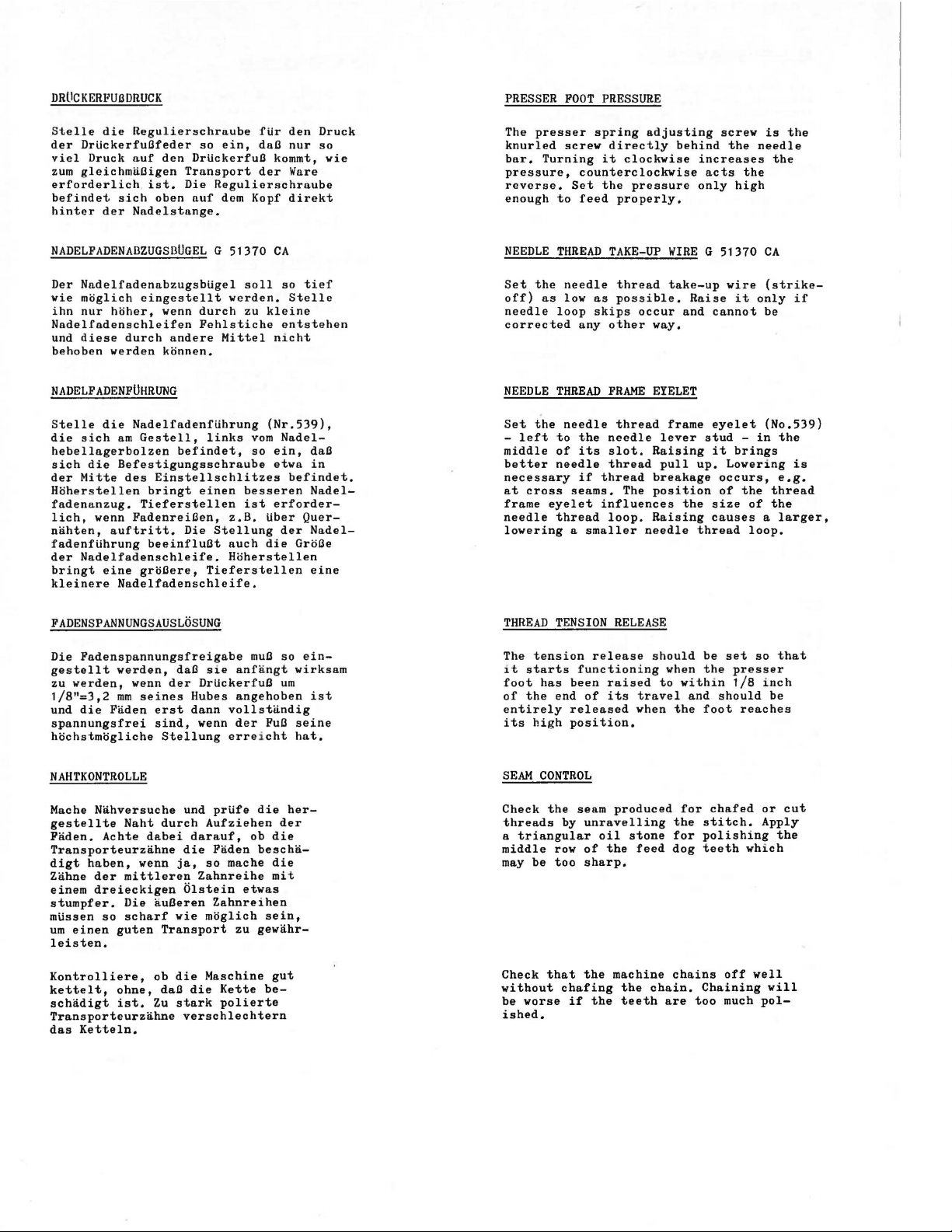
DRLICKERFUilDRUCK
PRESSER
FOOT
PRESSURE
Stelle
der
viel
zum
erforderlich
befindet
hinter
die
Regulierschraube
DrUckerfullfeder
Druck
auf
den
gleichmalligen
ist.
sich
der
oben
Nadelstange.
so
ein,
Drlickerfull
Transport
Die
Regulierschraube
auf
dcm
Kopf
NADELFADENABZUGSBUGEL G 51370
Der
Nadelfadenabzugsbtigel
wie
ihn
moglich
nur
hoher,
eingestellt
wenn
Nadelfadenschleifen
und
diese
behoben
durch
werden
konnen.
andere
soll
werden.
durch
zu
Fehlstiche
Mittel nicht
NADELFADENFUHRUNG
Stelle
die
hebellagerbolzen
sich
der
Hoherstellen
fadenanzug.
lich,
nahten,
fadenflihrung
der
bringt
kleinere
die
sich
Nadelfadenflihrung
am
Gestell,
befindet,
die
Befestigungsschraube
Mitte
des
Einstellschlitzes
bringt
Tieferstellen
wenn
Fadenreillen,
auftritt.
Die
beeinflullt
Nadelfadenschleife.
eine
grollere,
Nadelfadenschleife.
links
vom
so
einen
besseren
ist
z.B.
Stellung
auch
Hoherstellen
Tieferstellen
fUr
den
dall
nur
kommt,
der
Ware
direkt
CA
so
Stelle
kleine
entstehen
(Nr.539),
Nadelein,
etwa
befindet.
erforder-
tiber
der
die
Grelle
Druck
so
tief
dall
in
Nadel-
Quer-
Nadel-
eine
wie
The
presser
knurled
bar.
Turning
pressure,
reverse.
enough
NEEDLE
Set
the
off)
as
needle
corrected
NEEDLE
Set
the
-
left
middle
better
necessary
at
cross
frame
needle
spring
screw
directly
it
counterclockwise
Set
the
to
feed
THREAD
TAKE-UP
needle
low
as
loop
skips
any
other
THREAD
FRAME
needle
to
the
its
if
needle
slot.
thread
thread
of
needle
seams.
eyelet
thread
influences
loop.
properly.
thread
possible.
thread
lowering a smaller
adjusting
clockwise
pressure
WIRE G 51370
take-up
occur
way.
EYELET
frame
lever
Raising
pull
breakage
The
position
Raising
needle
screw
behind
the
increases
acts
only
high
wire
Raise
and
it
cannot
eyelet
stud -in
it
brings
up.
Lowering
occurs,
of
the
size
causes a larger,
thread
needle
the
only
the
of
loop.
is
the
the
CA
(strike-
if
be
(No.539)
the
is
e.g.
thread
the
FADENSPANNUNGSAUSLOSUNG
Die
Fadenspannungsfreigabe
gestellt
zu
1/8"=3,2
und
spannungsfrei
hochstmogliche
werden,
die
Faden
werden,
wenn
mm
seines
erst
sind,
dall
der
Drlickerfull
Rubes
dann
wenn
Stellung
s~e
vollstlindig
erreicht
NAHTKONTROLLE
Mache
Nahversuche
gestellte
Faden.
Naht
Achte
Transporteurzahne
digt
haben,
Zahne
der
einem
stumpfer.
mtissen
urn
einen
mittleren
dreieckigen
Die
so
scharf
guten
durch
dabei
wenn
aulleren
Transport
und
darauf,
die
ja,
Zahnreihe
Olstein
wie
moglich
prlife
Aufziehen
Faden
so
mache
Zahnreihen
leisten.
Kontrolliere,
kettelt,
schadigt
Transporteurzahne
das
Ketteln.
ohne,
ist.
ob
die
dall
die
Zu
stark
verschlechtern
Maschine
Kette
polierte
mull
so
anfangt
urn
angehoben
der
Full
die
her-
der
ob
die
bescha-
die
mit
etwas
sein,
zu
gewahr-
gut
be-
ein-
wirksam
ist
seine
hat.
THREAD
The
tension
~t
starts
foot
of
the
entirely
its
high
SEAM
Check
threads
a
triangular
middle
may
be
Check
without
be
worse
ished.
TENSION
functioning
has
been
end
of
released
position.
CONTROL
the
seam
by
unravelling
row
of
too
sharp.
that
the
chafing
if
RELEASE
release
raised
its
produced
oil
the
machine
the
the
teeth
should
travel
when
stone
feed
chain.
when
to
the
the
for
dog
chains
are
be
the
within
and
foot
for
stitch.
polishing
teeth
Chaining
too
set
presser
1/8
should
reaches
chafed
off
much
so
inch
be
or
Apply
which
well
will
pol-
that
cut
the
Page 13
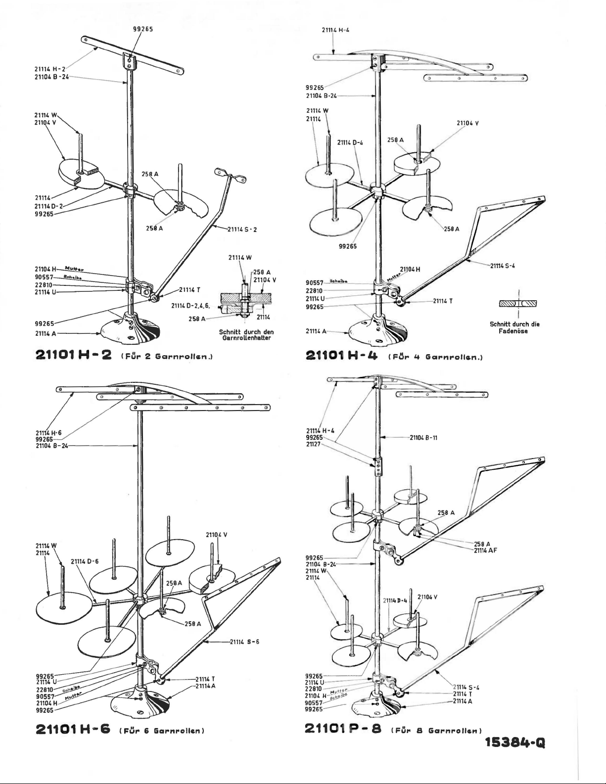
21114
21104 B
H- 2
-,~
------
-
21104
8·24
·---
-
-i
v
258 A
21104 v
258 A
21101
21114~
99265
21104 B-24-------<-1
H•2
~
<Far 2 Gc:arnrollan
/
Schnitt durch
GarnroU~nhatter
.l
0
den
0
0
"
21101
21114
H-4
99265
2n27
H • 4 C
11---
!=~to
'f
Gc:atonrollan.)
0
21104
B-11
Schnitt durch die
Fade
nose
0
0
21101
H • 6 C
Far 6 Garnrollcn
I
21101
P•
8 CFlJ,. S
Ga,.nrollc.nl
15384-Q
Page 14
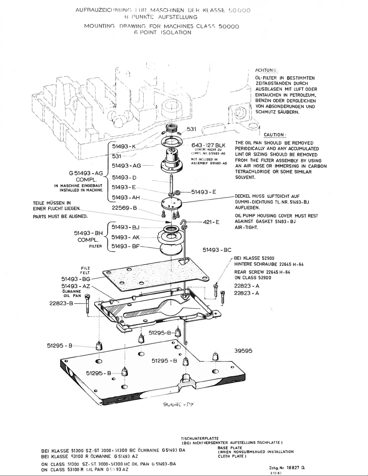
AUFRAUZEICIII'Illi\W,
b
MOUNTING
DRAWING FOR
I
tm
PLJ N KfE
fi
POINT
M!\SCHINEN
AUFSTELLUN G
MACHINES
ISOLATION
IJI
f-<
KlASS!:.
CLAc,c
,
50000
~
;0
CJOO
K:
..:-·-i ,-"['
ifj'\
I
"0-
1
\
,~J
TEILE MUSSEN
EINER
i \
\_ i !
\-J-
'ij
!1'~~
,
~~',-.'-l
'.I n\.'-.1 !
. · ! !
\
·,j
IN MASCHINE EINGEBAUT
FLUCHT
j(
~
·,,
' ' I '
,-
K""" . ....--.,
'·
\,_~\~\,]
~~
!,-:J',
",
1-
\
\:J
i
'
;<
'-~)
ill
.,
i
.,
. .
~.
"·
1
"·,
, _ _ •
'-iL.-----·-·
G51493-AG
INSTALLED IN MACHINE
IN
LIEGEN.
'\:,
r-·-J
i ·
j·
J.
b.
K"·-\ .
J.
·1-1
_
_.}.---·-·
jr-_
i
IJ'
COM PL.
k'
' ] I
I .
·,_
1.
,, "'
'-
·.,
t~~ l ;<:~:
>
-...
!
~
\ • . -.tl
-~
/~
i._(\_..,.-\_-,,LJ--.....i
·,
__
-,_
--<-·-
f--.1
:;::;.....-·-
51493-~
•
-------·-.
531
I I . j
~-'-.;
) 'l• :
,-\\,
~:----p
~
'-1
y i
1-~--'
~·
----·
-:_/
·-· . ./
!
··
i 1 ZEITABSTANDEN
.,
- .
~J:
_
...
_, . . j
.<::.:~.·-,
'·
(-.::.~:r·:
y
··-...
1-
..
_-::::-.:t:-.
..,...---,_,.--
./
,t;. •
..
./
/
.--
. .
r-··
__
___
-~~~~-
-·
; \
.
_.ljlj
:::;.J
531
,-;~::::>·-
\..
---·-
643-127
GE
HORI
CO
HPL. NR.GS149J·AG
NOT IN
CLU
ASSEMBLY G5149J ·
-
.
.}-··
;
J-'
_L . .:_.
--
'::.-
---·-
NICHI
DED
__
__?
~ f~
~
-1(rJ))ii
.,
i
':-:YJ_·
.-·~
...
. - -
)_
__
.
~
BLK
IN
THE
PERIODICALLY
ZU
LINT
FROM
AG
AN AIR
TETRACHLORIDE
SOLVENT.
DECKEL
GUMMI-
AUFUEGEN.
OIL
AGAINST GASKET 51493AIR-TIGHT.
ACHTUN G .
1
tiL-FILTER
j
./'
i
:~~~~~~~:~
i BENZIN
VON
ABSONDERUNGEN
SCHMUTZSAUBERN.
__
IJ·,
....
r'~'
'
~:..
A
I CAUTION :
OIL
PAN
SHOULD BE REMOVED
OR
PUMP HOUSING
AND ANY ACCUMULATED
SIZING SHOULD
THE FllJER ASSEMBLY
HOSE
OR
MUSS LUFTDICHT AUF
DICHTUNG
IN
BESTIMMTEN
DURCH
~~~~~~:;l~~~~
ODER
DERGLEICHEN
IMMERSING
OR
SOME SIMILAR
Tl.
NR.
COVER
BE
REMOVED
BY
IN
51493-BJ
MUST
BJ
UNO
USING
CARBON
REST
51493
-BC
r-
BEI KLASSE 52900
FILZ
FELT
~~~-=~~==~E~:.
'
I
I
«lb
51295-
I
:
I
s:=-$
CD
I
I
51295
-B
-
----
l
/ HINTERE SCHRAUBE 22645
/ REAR SCREW 22645 H
/
ON
CLASS
j
J
;;:~;::
52900
H-64
-64
«<b
9uu.:.!C -r"Y
T1
SCHU NTERPLA TTE
(BEl
NICHTVERSENKTER AUFSTELLUNG TISCHf'LATTE)
BEl
KLASSE 51300
BEl
KLASSE 'i3100 R OLWANNE G 51493
ON
CLASS
ON
CLASS 53100 R l-IL PAN G
51300
SZ-ST
SZ-ST
3000= 51300 BC OLWANNE G51493
3000•51300
~!t
93
HC
AZ
AZ
OIL
PAN G 51493-BA
BA
BASE PLATE
(WHEN
CLOTH
NONSUBMHWED
PLATE)
INSlALLATION
Zchg.Nr.
18
J 12 6 3
827
G.
Page 15
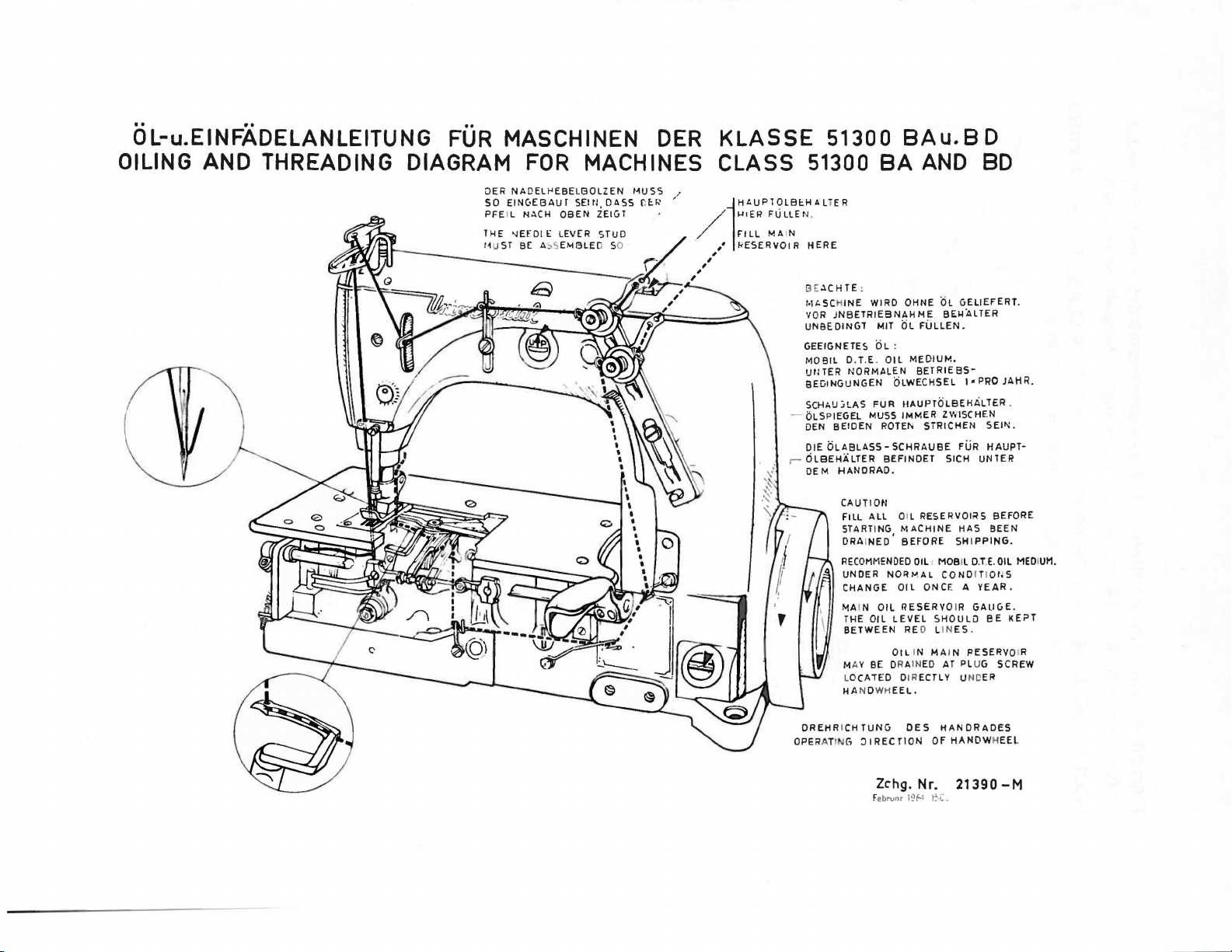
OL-u.EINFADELANLEITUNG
OILING
AND
THREADING
FUR
DIAGRAM
OER
SO
PFE
THE
11UST
MASCHINEN
FOR
NAOEll-'EBEl.80LZEN
EINC•EBAUf
IL NACH
'lEfDI
BE
MACHINES
SEltJ, OASS f:
OBEN
ZElCiT
1::
LEVER STUD
A~<;
EM13LE
D
SO
DER
t~USS
E:.r.•
KLASSE 51300
CLASS
••
'
-
r-
8Au.
51300
B E
ACHTE
t.lt.SCH
VOR
JNBETRIEBNAHME
UNBEDINCiT MIT OL
CiEEIGNETES
MOBIL
UtHER
BEDINCiUNGEN OLWECHSEL I •
SCHAU :.LAS
bLSPIEGEL
DEN
BElDEN
DIE
OLABLASSOLBEHALTER
OEM
8A
AND
:
INE
WIRO OHNE .
OL:
D. T.E.
OIL
NORMALEN
FUR
MUSS
ROTEt. STRlCHEN
SCHRAUBE
BEFINDET
HANDRAD.
CAUTION
FILL
ALL
STARTING
DRAINED •
RECOMMENDED
UNDER
NORt-~AL
CHANGE
"lA
IN
OIL
THE OIL
BETWEEN
MA Y
LOCATED DIRECTLY UNC
HANDWH
BE
LEVEL
OiL
DRAIN
EEL.
OL
BE~ALTER
FULLEN
MEDIUM.
BETRIESS-
fiAUPTOLBEHALTER.
IMMER
ZWISCHEN
SICH
OIL RESERVOIRS BEFORE
MACHINE
BEFORE
OIL
RESERVO
RE D LINES .
SHIPPING
OIL
• MOBIL
COND
ONCE A YEAR.
IR GALICiE.
SHOULD
IN MAI N PESERVO R
ED
AT PLUG SCREW
CiELIEFERT.
FUR
HAS
8 D
8D
.
PRO
SEIN.
HAUPT-
UNTER
BEEN
D.T.E.
I TI
Ot,S
BE
ER
JAHR.
.
OIL
KEPT
MEDIUM.
DREHRICHTUNCi
OPERATING
:ll
REC
Zchg.
Februnr
riON
DES
HANDRADES
OF
HAND WHEEl
Nr. 21390
l~f.4 ~C.
-M
Page 16
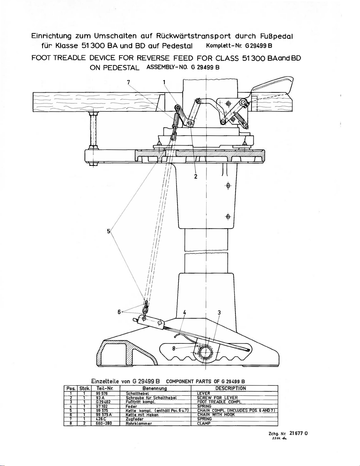
Einrichtung
fUr
Klasse
zum
51
Umschalten
300
BA
und BD
auf
RUckwartstransport
auf
Pedestal
Komplett-
durch
Nr:
G 29499 8
FuBpedal
FOOT TREADLE DEVICE FOR REVERSE FEED FOR CLASS
ON
PEDESTAL
ASSEMBLY-NO.
:;·,
I I
1·1
1/ 1
I I
'!'I
I 1
I I
'!'
t
I I
/.
,
I I
I
I'
t.,
I I
'I'
1.
1
Ill
I I
I I
I I
'!''
/-I
I I
'I'
I I
I I/
f .,
1ft
I 1
I
G 29499 8
2
-+
-
51
300
BAand BD
Pos.
1 1
2 1
3
4 1
5
6
8 2
Einzelteile
Stck.
1
Teil-Nr.
99
576
93A
G29402
97102
99
575
99
575A
4Z6C
660-280
von
G 29499 8
Schalthebel
Schraube
Funtrltt
Feder
Kette
kompl. ( enthiilt Pos. 6
Kette
mit
Zugfeder
Rohrklammer
COMPONENT
Benennul'lg_
fiir
Schalthabel
komDL
Haken
PARTS
LEVER
SCREW
FOOT
TREADLE
SPRING
u.
71
CHAIN
COMPL.
"HAIN
WIIH
SPRING
CLAMP
OF G 29499
DESCRIPTION
FOR
B
LEVER
COMPL.
lfN{l.MI!E::O__!"_OS._!!A!'i~L7
HOOK
Nr. 21677 0
Zchg.
2.3.64.
-Ia
Page 17

Einrichtung
fUr
Klasse
zum
51300
Umschalten
BA
und BD
auf
Ruckwdrtstransport
auf
Rohrgestell Komplett-Nr. G 29499 B
durch
FuBpedal
FOOT TREADLE DEVICE
ON
TABLE
-~-
--
-====-
............
--~----
--
FOR
STANDS
REVERSE FEED FOR CLASS
ASSEMBLY-
NO.
G 29499 B
51300
BAand BD
Stck. Teil-Nr.
Pos.
1
1
2
1
1
4
1
1
1
I 2
Einzelteile
99
576
93 A
G29402
97102
99 575
99
~75A
426 c
660-280
5
6
von
Schalthebel
Schraube
Funtritt
Feder
Kett
Kette
Zuafeder
Rohrklammer
G 29499 B
Benennung
fiir
ko'!!.J!l.
..
komal.
mit
Haken
COMPONENT
Schaltheb_el
enthiilt
Pos.li
PARTS
u.
7
LEVER
SCREW
FOOT
SPRING
CHAIN
CHAIN
SPRING
CLAMP
OF
G 29499 B
DESCRIPTION
FOR
LEVER
TREADLE
COMPL
W!!.H
COMPL.
:INCLUDES
HOO~
--
POS
__
. 6 AND7_l
-
-
Zchg.Nr.
d .
f44
21
701
0
Page 18

S60
780 -
Page 19

Ul
n
::r
a
)>
I
!D
• •
710
1 r
J
til
HI
ll~
-~
...
r
:
f
Jljli
7-j
'
~
(f{~
en
:::,.
.....
10
--t:~
c
' (
Page 20

-1-
43
54
-39
35
-
32
6
Page 21

l'os.
Ref.
10
11
15
18
19
21
22
25
26
28
)1
32
))
34
35
)6
37
38
39
40
41
42
43
44
45
46
47
48
49
50
51
52
53
54
12
13
14
16
17
20
23
24
27
29
)0
Tcil
l'nrt
GB
Nr.
No.
21375
93
98 A
52958
52 A
51282 y
22542
52882
51282
51282
22569
AH
B
'W
AC
z
B
Nr.
No.
2
3
4
5
6
7
8
9
7947
51294
p
51294 R
22513
G 35731 A
G
51370
CA
95
43296
57
'WB
605 A
15438
c
57
WD
22889
A
539
20
22848
51291 A
52882 y
90
52882
p
52882
AD
90
52882
AA
50-789
52882
AC
39582
L
22541 B
51282
AE
52882 u
52882
AE
22548
52882
M
52882
L
22848
51280
A
51280
J
80
87
41394
A
22733 B
51380
B
90
B c z c i c h n u n g
H•tnd
rndsc
hutz
Schrnube
Schrnube
FndenfUhrung
FndenfUhrung
Kopfdeckel
Schrnube
Dichtung
Einlage
Dichtung
Schrnube
Mutter
Olrohrprntze
Schrnube
Schrnube
FUhrungsplntte
Fndennbzugshaken
Verschluaschrnube
Halter
f.
Fndenvorspannung
F'Sp'Pliittchen
Schraube
Feder
Ansntzschrnube
Verschlu3schrnube
FadenfUhrung
Scheibe
Schraube
Greiferfadenschutzblech
Olspritzblech
Schraube
Dichtung
Kopfdeckel
Schraube
Olfangblech
Stift
Feder
Klappdeckel
Schraube
Olrinne
Dichtung
Abdeckblech
Schraube
Dichtung
Abdeckplatte
Schraube
Stichplattentrager
Stift
Schraube
Senkschraube
Stichplatte
f.
siehe
Stichplatte
Seite
Dichtung
Schraube
Unterlagplatte
Schraube
9
D c s c r i p t i o n
Belt
Guard
Screw
Screw
Eyelet
Eyelet
Head
Cover
Screw
Gasket
Felt
Liner
Gasket
Screw
Nut
Oil
Tube Clamp
Screw
Screw
Guide
Plate
Pull-off
Plug
Nipper
Nipper
Screw
Spring
Nipper
Plug
Eyelet
Washer
Screw
Looper
Baffle
Screw
Gasket
Crank
Screw
Drip
Pin
Spring
Oil
Screw
Needle
Gasket
Crank
Screw
Gasket
Oil
Screw
Throat
Pin
Screw
Throat
Throat
Gasket
Screw
Throat
Screw
Wire
Screw
Spring
Spring
Spring
Screw
Thread
Plate
Chamber
Plate
Filler
Lever
Chamber
Reservoir
Plate
Plate
Plate
Pl&te
Plate
Screw
Guard
Cover
Cover
Bearing
Cover,
Back
Support
Screw
see
Support
Cover
Page
Anznhl
Amt.Reg.
2
4
2
1
1
5
3
2
2
2
2
1
1
3
Oiler
lower
4
1
1
9
1
2
3
2
9
2
Shim
Page 22

-
-
- 2-
-
---
--
-
-
--~~-·
-
~
.
...--
,;---...
-
.--.__
~-":~-
\ -· / .
. ,--.:
s-·-/
\e
--·
("\
)\
_..-
\
.
\
52
\
35
r::~0
\
47
I
'
I
I
I
.
-f
27
I
I
I
I
A
~
25
8
D
-
23
D
c
.-o
1
21
F
G
~
60
E .
~
18
~
H
~
11
61
58
~
·e
24
22
· v
:~
~
~20
'
-18~
1~
.. :.e? .
..
..
·.·
.·
.·.·
..
•
. ..
. .
..
. .
w
8
9
Page 23

Pos.
Ref.
Nr.
No.
Teil
Part
Nr.
No.
B e z e i c h n u n g
D e s c r i p t i o n
~
Amt.Rcq.
10
11
12
1J
14
15
16
17
18
19
20
21
22
23
24
25
26
27
28
29
JO
Jl
32
JJ
34
35
)6
37
JS
39
40
41
42
43
44
45
46
47
48
49
50
51
52
53
54
55
56
57
58
59
60
61
1
2
J
4
5
6
7
8
9
643-127
G 51493
531
51493
51493 D
51493 E
51493
G 51493
22569 B
22823 A
51493
51493 BJ
51493
51493
G 22823 B
51493
51493
22571 A
666-114
35178 D
666-65
666-118
666-111
666-179
22539 H
52836 R
52890
51290 T
52836
660-136
52894
22560 B
52894
52794 G
51257
51254 D
51254
51242 s
51244 M
52894
6042 A
51242 R
51242
21657 X
52891 B
51290 R
50-434
G
G 51336 A
52883 R
667 C-8
51295 B
39595
51493
22571
51493
22889 c
22889 D
258 A
90
258 A
421
E
BQ
AG
AH
AG
BH
AK
BF
AZ
BG
c
p
AK
AB
AA
c
AM
z
BK
BC
BLK
Dichtung
Kegelrad
Schraube
Olpumpengehii.use
Pumpenachse
Zahnrad
Gehii.usedeckel
Olpumpe
kompl.
Schraube
Schraube
Filter
kompl.
Gummi-Dichtung
Filterblech
Filz
Schraube
Olwanne
Filz
VerschluBschraube
Olfilz
Feder
Olfilz
Olfilz
Olfilz
Stift
VerschluBschraube
Buchse
Buchse
Hauptachsbuchse
Buchse
Olrohr
Mutter
Olrohr
Schraube
Olrohrhalter
Olrohr
Schraube
Buchse
Buchse
Buchse
Buchse
Buchse
Olrohr
U'Lagscheibe
Mutter
Buchse
Buchse
Buchse
f.
Fadenspannerachse
Hauptachsbuchse
Buchse
Olstandsauge
Buchse
Buchse
f.
Nadelhebelachse
Stift
Gummi-Isolator
Gummi-Isolator
Olsieb
Schraube
Haken
Zugstange
VerschluBschraube
VerschluBschraube
Mitte
Gasket
Oil
Pump
Driven
Screw
Oil
Pump
Pump
Pump
Pump
Pump
Housing
Driving
Driving
Housing
complete
Oil
Oil
Oil
Oil
Screw
Screw
Filter
Cap Assembly
Rubber-Washer
Oil
Filter
Cap
Wick
Screw
Base
Plate
Wick
Plug
Screw
Oil
Wick
Spring
Oil
Wick
Oil
Wick
Oil
Wick
Pin
Plug
Screw
Bushing
Bushing
Main
Shaft
Bushing
Bushing
Oil
Tube
Nut
Oil
Tube
Sc"rew
Oil
Tube
Oil
Holder
Tube
Screw
Bushing
Bushing
Bushing
Bushing
Bushing
Oil
Tube
Washer
Nut
Bushing
Bushing
Front
Looper
Shaft
Main
Bushing
Shaft
Bushing
Bushing
Lucite
Oil
Gauge
Bushing
Foot
Lifter
Pin
Haunting
Maunting
Lint
Isolator
Isolator
Filter
Screw
Hook
Lifter
Plug
Plug
Link
Screw
Screw
Gear
Drive
Lever
Screen
Shaft
Shaft
Cover
Lever
Bushing
Gear
1
1
2
1
1
2
1
1
3
2
1
1
1
1
1
1
1
15
2
2
2
2
2
2
1
1
2
1
2
1
1
1
1
1
1
2
1
1
1
1
1
1
1
1
1
1
1
1
1
1
1
1
2
5
1
1
2
1
1
2
1 .
Page 24

-3-
.c/50
~-/51
@"~52
~
53~~'
54
lj.._49
'
'\.....--"" _ __......
47
'
~
\
4~
45
'
37
Page 25

l'os.
Ref.
Nr.
No.
Tcil
Part
Nr.
No.
B c z c i c h n u n g
D e s c r i p t i o n
Anznhl
Amt.Rcq.
10
11
12
13
14
15
16
17
18
19
20
21
22
23
24
25
26
27
28
29
30
31
32
33
34
35
36
37
38
39
40
41
42
43
44
45
46
47
48
49
50
51
52
53
54
55
56
57
58
59
60
61
62
63
1
2
3
4
5
6
7
8
9
22729
51243 c
29105 z
22559
A
22559
B
22894
c
22894 D
22852
A
81
51242 M
51242
y
52841 J
51242 M
52841 G
12982
51242 p
22883 A
51242 L
51493
BP
531
29476
FF
Schro.ube
Ftihrungsgo.bel
Grei~cro.ntricbsexzcntcr
kompl.
Schro.ube
Schro.ube
Schro.ube
Spitzschraube
Schro.ube
Schro.ube
Scheibe
Greiferweg-Antriebsro.hmen
Mutter
Scheibe
Spo.nnungsschro.ube
Gegenmutter
Greifero.ntrie~so.chse
VerschluOschro.ube
Anlo.ufscheibe
Pumpenkegelro.d
auf
Ho.uptwelle
Schro.ube
Kurbelwelle
Besteht
kompl.
nus:
1-51216 J Lo.gerscho.le
28-51216
M Lo.gerno.del
1-51222 D Kurbelwelle
51216 M
51247
22894
51147
95
22569
52921 B
22894 G
56
51217
G 196
22585 A
652
C-9
22768
51258 A
29348
51254 H
22562 A
54
78
51054
666-149
77
51215 J
51250
666-170
51250
E
719
22586
51250 F
51250
660-212
51150
29066 R
J
B
c
p
A
R
D
Lagernadel
Ausgleichsgewicht
Schraube
Stell
ring
Schraube
Schraube
Handrad
Schraube
Nadelstangenmutter
Nadelstange
Nadelo.nschlo.g
Senkschraube
Zahnscheibe
Schraube
Fadenftihrung
Nadelhebel
auf
kompl.
Nadelstange
Nadelstangenmitnehmer
Schraube
Verbindungsgelenk
Senkschraube
Kon.
Gelenkstift
Oldocht
Schraube
Nadelhebel
Buchse
Filz
Nadelhebelachse
Schraube
Schraube
Dichtung
U'Lagscheibe
Olabstreifring
Anschlagbuchse
Kugellager
Besteht
kompl.
aus:
1-51216 K Lagerschale
22559 G
51216 N
51216
p
51216 G
22768
51258
51190
D
660-202
1-51216
Schraube
Scheibe
Mutter
Nadelhebelverbindungsstange
Schraube
Fadenftihrung
Dichtung
Dichtungsring
L Kugel
f.
Handrad
Screw
Guide
Fork
Looper
Drive
Lever
Assembly
Screw
Screw
Screw
Eccentric
Spot
Screw
Screw
Washer
Looper
Drive
Lever
Nut
Washer
Locking
Stud
Nut
Looper
Plug
Thrust
Oil
Drive
Screw
Pump
Lever
Washer
Driving
Screw
Crank
Shaft
Assembly
includes:
1-51216 J Bearing
28-51216 M Needle
1-51222 D Crank
Needle
Roller
Counterweight
Screw
Adjusting
Collar
Screw
Screw
Pulley
Screw
Needle
Needle
Needle
Clamp
Bar
Guard
Nut
Screw
Eyelet
Lock Washer
Screw
Needle
Needle
Needle
Bar
Lever
Bar
Thread
Assembly
Connection
Screw
Needle
Bar
Connection
Screw
Link
Pin
Lubricating
Felt
Screw
Needle
Lever
Bushing
Felt
Wick
Needle
Lever
Stud
Screw
Screw
Gasket
Washer
Oil
Seal
Needle
Needle
Ball
Ring
Lever
Lever
Assembly
Thrust
Connecting
includes:
1-51216 K Bearing
1-51216 L Ball
Screw
Washer
Nut
Needle
Lever
Connecting
Screw
Eyelet
Gasket
Oil
Seal
Ring
Screw
Gear
Roller
Shaft
Eyelet
Eccentric
Rocker
Shaft
Link
Collar
Rod
Rod
2
2
4
1
1
1
1
1
1
1
1
1
1
1
2
1
2
1
1
28
1
28
1
2
1
2
3
1
2
1
1
1
1
1
1
1
1
1
1
1
1
2
1
1
1
1
1
1
2
1
1
1
2
1
1
1
2
1
1
2
1
1
1
1
Page 26

-4-
Page 27

Pas.
Ref.
Nr.
No.
Teil
Part
Nr.
No.
Bezeichnung
Descrietion
Anzahl
Amt.
Req.
z
3 ZZ894 H
4
5
6
7
8
9
10
11
lZ
13
14 18
15
16 Z69
17
18
19
20
Zl
zz
Z3
Z4
Z5
Z6
Z7
Z8 73
Z9
30
31
3Z
33
34
35
36
37
38
39
40
41
4Z
43
44
45
46
47
48
49
50
51
5Z
53
54
51Z4Z W
ZZ811 B
1Z538
51Z41
56341
50-430
G
55Z41
35853
660-310
51Z41
55Z41
51741
51Z40
55Z41
55Z41
55Z41
Z919Z
ZZ8Z9
Z58 A
15465
88
51Zl3
51745
5Z8Z5
ZZ596 B
ZZ563
513Z5
51Z44
51Z46
5Z444
98
96
77
51Z44
ZZ519 H
51308
51144
55Z44
51Z44
zo
18
Z9476
51145
51406
96
51Z36
666-149
G 513ZZ
5Z470
18
K
G
D
V-156
H
B
E
D
N
P
Q
F
D
L
B
B
G
N
DV
A
A
BD
Greiferantriebshebe1
Schraube
Schraube
Mutter
Greiferkugellager
stange,
B1attfeder
Stift
Greiferantriebsstange
Scha
Sicherungsring
Lagerschale
Kugelschraube
Anlaufscheibe
Mutter
Greife
Mutter
Greiferkugellager
Lagerschale
Kugelschraube
Greiferhebel
Schraube
Mutter
Konus
Schraube
Greiferhebel
Konusbolzen
Mutter
Befestigungsschraube
Halter
Schraube
Schraube
Nadelanschlag
Anlaufscheibe
Mutter
Greiferhebelrahmen
Schraube
Schraube
Schraube
Greiferseitweghebel
Schraube
Greifer
Greiferhebelachse
Bolzen
Stellring
Scheibe
Mutter
Greiferseitwegexzenter
Gelenk
Exzenter
Schraube
Gelenkstift
Oldocht
Hauptwelle
Anschlag-Winkel
rechts,
f<lr
Feder
rnierstift
rve
C.
f.
f.
auf
mit
komp1.
rbindungs
kompl.
vorderen
vorn
Konusbolzen
Stellring
Greiferachse
Nadellager
und
Verbindungs-
stange
links
kompl.
f.
Greifer
Nadelanschlag
kompl.
kompl.
Looper
Screw
Screw
Nut
Looper
right,
Spring
Pin
Looper
Hinge
Truarc
Bearing
Ball
Thrust
Nut
Looper
Nut
Looper
Bearing
Ball
Looper
Screw
Nut
Looper
Screw
Looper
Looper
Nut
Screw
Holder
Screw
Screw
Looper
Thrust
Looper
Looper
Screw
Screw
Screw
Looper
Screw
Looper
Looper
Locking
Looper
Washer
Nut
Looper
Eccentric
Eccentric
Screw
Link
Lubricating
Main
Stop
Connecting
campi.
for
Spring
Pin
Screw
Washer
Connecting
Connecting
Rocker
Rocker
for
for
Needle
Washer
Rocker
Rocker
Rocker
Rocker
Rocker
Avoid
Pin
Shaft
Bracket
Drive
Drive
Ring
Lever
Rocker
Looper
front
Stud
Bearing
Felt
Lever
Rod
Rod
Rod
Rod
campi.
Cone
Cone
Needle
Guard
Stud
Frame
Shaft
Shaft
Shaft
Eccentric
Stud
Nut
Arm
Clamp
Ball
Joint,
Ball
Joint
Guard
Collar
Assembly
left
campi.
1
z
z
1
1
z
z
1
z
Page 28

-5-
Page 29

Pos.
Ref.
Nr.
No.
Teil
Part
Nr.
No.
Bezeichnung
Description
Anzahl
Amt.
Req
10
II
12
13
14
15
16
17
18
19
20
21
22
23
24
25
26
27
28
29
30
31
32
33
34
35
36
37
38
39
40
41
42
43
44
45
46
48
49
50
51
52
53
54
55
56
57
58
59
60
61
62
63
64
65
66
67
68
69
70
71
72
73
G
29476
I
G
2
4
G
5
6
7
8
G
9
G
G
G
G
G
G
G
G
G
G
G51235A
G
G
G51145A
G
G
G
G
G
G
G
G
G
G
51333
61436
482
51335
51134
51134
51134
51334
51334
538
51134
258
22863
51134
22560
HA
51336
96505
51336
99284
61433
51346
51346
G
51334
51235
22565
51236
660-169
269
51236
51322
29476
51142
666-149
51236
51345
22894
51338
136
G
460
374
51345
53373
51338
51338
51348
136
G
15872
51347
51347
7947
22562
51345
22528
51345
99276
21657
BA
98
C
88
B
SA
R
p
c
A
J
A
H
B
77
73
B
B
A
93
A
50-553
B
c
F
20
G
82
BD
DR
c
96
A
C
J
B
A
50-497
A
50-497
F
A
A
A
B
E
Transport
Transportantriebshebel
Schraube
Gleitstein
Schraube
Stell
Transport
Transportachse
Filzhalter
Filz
Transporteurtrll.gerachse
Transporteurtrll.ger
Transporteurtrli.ger
Schraube
Scheibe
Mutter
Schraube
Transporteurhalter
Schraube
Schraube
Schraube
Bolzen
Bolzen
Trans
Ansatzschraube
Gelenk
Steuerhebel,
Schraube
Bolzenhebel
Bolzen
Achse
Verbindungsstange
Verbindungsstange
Schraube
Buchse
Nadellager
Scheibe
Mutter
Transportge1enkbolzen
Schraube
Hauptwelle
Transporthubexzenter
Exzenter
Schraube
Gelenk
Oldocht
Gelenkstift
Handhebel
Schraube
Lagerbock
Schraube
Stift
Stell
Schraube
Steuerwelle
Mutter
Buchse
Lagerbock
Anschlagring
Schraube
Stift
Zugfeder
Feder
Bolzen
Mutter
Schraube
Steuerhebel
Schraube
Lenker
Schraube
Unterlagscheibe
kompl.
ring
rahmen
im
Transporteurtrli.ger
im
Kulissenste
portantrie
fUr
Verbindungsstange
(Linksgewinde}
mit
Nadellager
rechts
ring
links
halter
f.
Federhalter
aul.len
bsgabel
innen
kompl.
in
kompl.
mit
Kulisse
Feed
mechanism
Feed
Rocker
Screw
Cam
Follower
Screw
Adjusting
Feed
Rocker
Feed
Rocker
Lubricating
Felt-Wick
Feed
Bar
Feed
Bar
Feed
Bar
Screw
Washer
Nut
Screw
Feed
Dog
Screw
Screw
Screw
Feed
Bar
Stud
for
Feed
Bar
Shoulder
Link
Connection
Link
Screw
Lever
with
Stud
Shaft
for
Feed
Rocker
Feed
Rocker
Screw
Bushing
Needle
Washer
Nut
(left
Feed
Crank
Screw
Main
Shaft
Feed
Lift
Eccentric
Screw
Eccentric
Oil
Wick
Link
Pin
Handle
Screw
Actuating
Screw
Pin
Adjusting
Screw
Actuating
Nut
Bushing
Actuating
Thrust
Screw
Pin
Spring
Spring
Stud
Nut
Screw
Link
Screw
Link
Screw
Washer
Collar
Bracket
for
Lever
Collar
Felt
Shaft
compl.
Holder
Stud
Cam
Link
Screw
Stud
Feed
Bearing
thread}
Stud
Eccentric
Bearing
Shaft
Collar
Shaft
Shaft
Spring
compl.
with
Cam
Shaft
Guard
Follower
Rocker
Arm
compl.
Arm
Bracket
Bracket,
Bracket
Arm
Assembly
right
left
5
I
3
2
2
1
4
2
2
I
I
2
2
2
I
2
2
2
Page 30

-6-
~
I
1
I
Page 31

Poe.
Ref.
Nr.
No.
Teil
Part
Nr.
No.
B e z e i c h n u n g
D e s c r i p t i o n
Anzahl
Amt.Reg.
10
11
12
13
14
15
16
17
18
19
20
21
22
23
24
25
26
27
28
29
30
31
32
33
34
35
36
37
38
1
2
3
4
5
6
7
8
9
51351 G
22585 A
22570 A
51351 F
51351 E
J
51351
29126
DR
604
22757 F
51351 D
61451 D
51351 B
51382
c
51351
51382 A
667 C-8
51351 A
22580 E
39147 D
88
51351
98
51351 H
51423
c
96
22580 D
51357 A
50-216
BLK
51204 A
22798
A
51204
51204
.B
J 87 J
77
51204 c
21657 E
22528
51311
Halter
Schraube
Schraube
FUhrung
SchlingenrUckhalter
Abstandsscheibe
Kurbelantrieb
Schraube
Schraube
Gelenk
Lagernadeln
Kurbel
Oberer
Buchse
Dichtung
Stift
Zahnrad,
Schraube
Stellring
Schraube
Zahnrad,
Schraube
Zwischenring
Fadenaufnehmer
Schraube
Schraube
Fadenabzugsplatte
Stift
Halter
Schraube
FadenrUckhaltefinger
Fadenabzugsfinger
Schraube
Schraube
Halter
Scheibe
Schraube
Fadenabzugsdraht
f.
FUhrung
kompl,
f.
SchleifenrUckhalter
Deckel
f,
tilkammer
getrieben
treibend
f,
Abzugsfinger
f,
Fadenabzugsfinger
Fulcrum
Screw
Screw
Eyelet
Loop
Shim
Crank
Screw
Screw
Link
Needle
Loop
Oil
Crank
Gasket
Pin
Loop
Screw
Adjusting
Screw
Loop
Screw
Drive
Take-up
Screw
Screw
Cast-off
Pin
Retainer
Screw
Retainer
Cast-off
Screw
Screw
Auxiliary
Washer
Screw
Loop
Bearing
Retainer
(as
required)
Drive
Bearing
Retainer
Reservoir
Bushing
Retainer
Collar
Retainer
Gear
Wire
Finger
Cast-off
Retaining
Bracket
Hook
Assembly
Rollers
Driving
Top
Driven
Driven
Spacer
Support
Holder
Wire
Crank
Cover
Gear
Gear
Support
1
9
2
2
16
2
2
1
2
1
2
1
2
2
Page 32

-7-
13
~~2
7
Page 33

Pos,
Ref.
Nr.
No.
Teil
Part
Nr.
No.
B e z e i c h n u n g
D e s c r i p t i o n
Anznhl
Amt.Req.
10
11
12
13
14
15
16
17
18
19
20
43266
51491
2
3
6
7
8
9
c
51292 D
51292
51292 G
109
51292
A
P-8
51292 c
51292
F-2
22598 c
80557
21657-3
52892
K
51257
51257 M
531
402
51256 c
Mutter
PadeneinfUhrung
FadenfUhrung
PadenspannungshUlse
Fadenspannungsbolzen
F'Sp'Scheibe
N'P'Sp'Feder
F'Sp'Mutter
Gr'F'Sp'Feder
Schraube
Scheibe
Padenentspanner
Padenspannungstrager
DrUckerfuDstange
DrtickerfuDverbindung
Schraube
Ansatzschraube
DrUckerfuDfeder
u,
Ftihrung
Nut
Thread
Tension
Tension
Tension
Tension
Tension
Tension
Tension
Screw
Washer
Tension
Tension
Presser
Presser
Guide
Screw
Nipper
Presser
Lead-in
Thread
Post
Post
Disc
Spring-Needle
Nut
Spring-Looper
Disc
Post
Bar
Bar
Spring
Bar
Guid
Eyelet
Ferrule
Separator
Support
Connection
Screw
Spring
2
2
2
2
4
2
2
and
21
22
23
24
25
26
27
28
29
30
31
32
33
34
51256 N
53783 L
52883 s
22557 B
22758 c
53783 A
53783 M
53783 N
22537
660-207
G 51283 H
21657 y
22596
21657
li
DrtickerfuD-FUhrungsbuchse
liinkelhebel
Feder
Schraube
Schraube
Lifterhebelgelenk
Verbindungsstange
Lifterhebel-VerbindungsstUck
Schraube
Olabstreifring
DrtickerfuD-Lifterhebel
Spannungsiiffner
Verbindungssttick
Schraube
Spannungsiiffnerstange
f.
Lifterhebel
f.
Lifter
f.
Lifter
f.Lifterhebelbuchse
u.
oben
Presser
Lifter
Lifter
Screw
Screw
Lifter
Presser
Connecting
Lifter
Screw
Oil
Lifter
Tension
Connection
Screw
Tension
Lever
Lever
Lever
Lever
Lever
Seal
Lever
Shaft
Springs
Foot
Rod
Ring
Release
Release
Regulator
Bell
Bell
Link
Lifter
internal
Lever
and Lif
Crank
Crank
Lever
Spring
Shaft
ter
Page 34

- 8 -
~9
I 1
Page 35

Pos.
Ref.
Nr.
No.
Teil
Part
Nr.
No.
B e z e
c h n u n
i
g
D e s c r
i
t i o n
!:!
~
Amt.Req.
G
51301
2
3 22839
4
5
6
7
8
9
10
11
12 22848
13
14 99295
15
16
17
18 52978
19
80
51281
35772
22760 A
22845
51281
-222
24
25
G
51382
G
51381
G 51381
G 51282
51282
25
D
c
AC
H
B
AS
BA
BD
BA
AJ
AK
G
s
Tischplatte
Schraube
Schraube
Feder
Scheibe
Schraube
Schraube
Tischplattendeckel
Stoffanschlag
Schraube
Winkel
Schraube
Abdeckblech
Schraube
Abdeckblech
Abdeckblech
Feder
Stift
Schraube
Tischplattendeckel
f.
Abdeckblech
f.
hinten
links
vorn
kompl.
Cloth
Plate
Screw
Screw
Cloth
Plate
Washer
Screw
Screw
Cloth
Plate
Edge Guide
Screw
Bracket
Screw
Oil
Screw
Oil
Oil
Spring
Pin
Screw
for
Shield
Shield
Shield
Cover
Cover
Oil
rear
left
front
3
2
Spring
3
3
2
Shield
3
4
cpl.
2
2
Page 36

-9-
Page 37

Pos.
Ref.
Nr.
No.
Teil
Part
Nr.
No.
B e z e i c h n u n g
D e s c r i p t i o n
~
Amt.Reg.
10
11
12
13
14
15
16
17
18
19
20
21
22
23
24
25
26
27
28
29
30
31
32
33
34
35
36
G
51305
BA
2
3
4
5
6
7
8
9
22528
G 51324
51320
22768
41358
G 21695 P
1741 B
91
BA
N
1741 A
G
51330
AK
1025104
(12,0
1025104 ( 8,0
G
51330
AL
51330
w
51330
AM
G 51305
G 51324
G
G
G
1025104
51320
51330
51330
BE
BD
C
A
(15,5
51930
G 51330 B
G 51305
G 51324
G 51320
G 51330 D
G 51330 E
1025108
G 51320
G 51330
G 51305
G 51330
CA
CA
KE
22840 A
51430 F
(12,6
CA
CB
BD
CA
Transporteur
Schraube
Stichplatte
DrUckerfua
Schraube
Scheibe
Fingerschutz
Abschneidmesser
Schraube
Stift
DrUckerfuanabe
Stift
lg)
Stift
lg)
DrUckerfuasohle
Feder
Kettelplil.ttchen
Transporteur
Stichplatte
DrUckerfua
DrUckerfuanabe
DrUckerfuCsohle
Stift
lg)
Feder
Kettelpliittchen
Transporteur
Stichplatte
DrUckerfua
DrUckerfuanabe
Schraube
Mutter
DrUckerfuasohle
Stift
lg)
DrUckerfua
G 51320
DrUckerfuanabe
Transporteur
DrUckerfuasohle
kompl.
1,4P X 12,0
1,4P X 8,0
kompl.
1,4~
x
15,5
kompl.
1,8~
X
12,6
kompl.
KE
lg.
lg.
lg.
lg.
ersetzt
durch
Feed
Dog
Screw
Throat
Presser
Screw
Washer
Finger
Chain
Screw
Pin
Presser
Pin
1,4~
Pin
1,4~
Presser
Spring
Presser
Feed
Dog
Throat
Presser
Presser
Presser
Pin
1 14P x
Spring
Presser
Feed
Dog
Throat
Presser
Presser
Screw
Nut
Presser
Pin
1,8~
Presser
by
G
51320
Presser
Feed
Dog
Presser
Plate
Foot
Protector
Cutting
Foot
x
12,0
x
Foot
Foot
Plate
Foot
Foot
Foot
15,5
Foot
Plate
Foot
Foot
Foot
X
12,6
Foot
KE
Foot
Foot
compl.
Knife
Shank
lg.
8,0
lg.
Bottom
Yielding
compl.
Shank
Bottom
lg.
Yielding
compl.
Shank
Bottom
lg.
compl.
Shank
Bottom
1
3
1
3
3
3
3
3
3
Section
2
Section
replaced
Page 38

OLSIPHON
51294 p
I
OIL
/-~
' I) '
/.
I/
-----------
I i
.
SIPHON
-
-
""'
~
\
----
-\\
\\
.
-
-
51294
-
M
-
51294N
.
---~....-=-
'\
21212
~
-
\
-
_:_-:--.:._
-
~~:;---........._
--
:.---
---------
---
--·")
/'
/'
;"""'
'
666-201
666-209
643-263
22729 8
I
22729~
0
.--
51294R
7947
666-214
--
(
·"-...
~
_
"-...._
-
"-....
\ U l "
.\
.\ !2--
'\:---.J
-
-
"-...
.""-...
""-...
I!>
I
I~
j I
;
IUY
'-
~
~
~-
_/o('f.
/ J . I I
..
./
I
r·-.t-·/
. I
_j__
____
J /
/
/-----------
;/
/'
------------------
-------------------(
-
-
-
-
-
fur
Klassen:
for
Styles:
52 700
52100
51300
51400
51200
~
--
·
-...........
\
.
\
~-
.
\
""-
-
\
\
\
51294
.
Compl.
\
!
I
_..?:~
~
'---
---------~----
.
I
i
.
I
I
)-......·
--....:._~~~
(-...::::::-:-,
______
u
j
Zchgs.Nr.
Drawing
No.
20193
,..
Page 39

Teil
Part
Nr.
No.
B e z e i c h n u n g
D e s c r i p t i o n
~
Amt.Req.
28-182
643-263
666-201
666-209
666-214
7947
21212
22729
22729
51294
51294
51294
51294
51294
51294
R
u
A
B
K
M
N
p
Unterer
Klemmbacken
Olsyphon
Filzstopfen
Filzscheibe
Olfilz
Mutter
Ring
fUr
Olsyphonverbindung
Schraube
Schraube
Oberer
Klemmbacken
Olrohr
Olrohrverbindung
Klemme
fUr
tllrohr
Schraube
tllsyphon
kompl.
Clamp,
Oil
Siphon
Felt
Plug
Felt
Plug
Felt
Lint
Nut
Locking
Screw
Screw
Clamp,
Oil
Tube
Oil
Tube
Oil
Tube Clamp
Screw
Oil
Siphon
lower
Filter
Ring,
upper
Connection
Assembly
for
oil
siphon
connection
Page 40

~
~
,-
....
I
'-...
I '
I/.--
l/
n t-
II
,,
I
'"
~.......
'
...--'
(''-...
,....__ / I I
__..,..-..'{
\
\
....
"\
'..J
I
>''/II
:II
........... I II
,1\(
t\
1
1)
II
95115
(
fUr
for Ped11tal
Pedettal)
u
Knee press assembly
Kniehebel
kompl.
21660 H
21662 r
1662
s
39536 AD
557 A
Zchg.Nr. 21278
24.4.
63
j
-N
Page 41

Teil
Part
Nr.
No.
B
e z e i c h n u n g
D e s c r i p t i o n
Anzahl
Amt.Req.
21660 H
660-168
21664
A
21663
22650 CE-6
21662
R
660-219
AD
39563
12982
92201
21664 p
21662 v
80
sc
303
21662 u
21664
c
22557
A
43137
E
39536
AD
22894 z
21662 s
21662 T
95115
G
Kniehebel
Gummipolster
Kniedruckscheibe
Hebelstange
Schraube
Verbindungshebel
Rollenbolzen
Scheibe
Mutter
Einstellschraube
Kniehebeltrii.ger
Feder
Schraube
Holzschraube
Lifterhebel
Winkelsttick
Schraube
Scheibe
Scheibe
Schraube
Verbindungsgelenk
Verbindungsstange
Schraube
komplett
zur
f.
Pedestal
Kniehebelbefestigung
Knee
press
Knee
Press
Knee
Press
Knee
Press
Screw
Connection
Roll
Pin
Washer
Nut
Adjusting
Mounting
Spring
Screw
Wooli
Screw
Knee
Press
Bracket
Screw
Washer
Washer
Screw
Connection
Connection
Screw
for
assembly
Plate
Plate
Plate
Lever
Screw
Bracket
Lever
Link
Pedestal
Cushion
Rod
2
2
2
Page 42

N
~
•
I
I
I
19-~~
17
I
I
I
' f / /
'-
....._
<::-J
/'
I
',,
I
"--
1.1
['\
M '
,,
' " ' I I I I
1
'-
',
''I I I,,
I
I\'.>/
' '
.
,I
' \
' I
I
__
.......
1
\''
'
',j
\ I
--
\ I /
--""
,,~--..1
I
...._--_::....-...-...--
I
I /
\
___
'
........
.,"'
/
r--......
: /
1/
I
/1
I!
1
I
II
I I , I
1
1
I
1
II
I
)il
I
I
1'111
I
1 1 1 1 1 1 '
1 I
I II I
II I
~L
\
--l
..............
,J"
.........
1//f
If,'
1111
~~~
1111
t\'
I'
l1
II
II
\
'
\
'...._
/\\
.........
I
I
I
I
I
I
I
I
----J
--
-....
.......
..........
_:;::::::::::=:
/~
--,....
/,/
/_,._.,.. I
II///
/11/
/
1
;
I
I 1, '
I
II//,.,,\
1
I 1
I
't'
I , _
'I
II
'\
1\ / /1
',1\.--'"
/
*'
~_..
.
...-
I'
\\
,,
\\
...-""
'-\)
'-,
/...--":>-l...... ' '\
1/,-
I I ' / ; I ' II
\I
"~--~/
..........
-........' \ ....
...--.:::----::;:.
,;/
,-.._
L-
,,, /
,_/
_-'I
I
~~
---_......-""
/
...
...,.~
'
~'
'-
'-...._,
,,,
,,
'
',',
:
\\
1
,
' r ' \
II
II
~~
...-
''
\
,,
\
II
I
II
I
),
,''t............
_/
/
/
,,
-/
,,
,,
'I
','
I
'-\l
I
Kniehebel zum Einschalten des Ruckwiirtstransport.
Knee
Press
Assembly
for
Actuating
Reverse
Feed
Mechanism .
Page 43

Pos.
Ref.
Nr.
No.
Teil
Part
Nr.
No.
B e z e i c h n u n
g
D e s c r
i
t i o n
l!
~
Amt.Req.
10
11
12
13
14
15
16
17
18
19
20
51345
2
3
4
5
6
7
8
9
660-168
21664
21663
A
22650 CE-6
21662 R
22560
B
AD
39536
12982
92201
21664 F
21662
v
80
660-219
51345 A
51345 B
22569
660-283
22516 A
G
460
G
c Si
Betatigungshebel
Gummipolster
Kniedruckscheibe
Hebelstange
Schraube
Verbindungshebel
Schraube
Scheibe
Mutter
Einstellschraube
Kniehebeltrager
Feder
Schraube
Rollenbolzen
Stellring
Verbindungsstange
KlemmstUck
Schraube
cherungsring
Schraube
Knee
Press
Actuating
Knee
Press
Plate
Knee
Press
Plate
Knee
Press
Plate
Screw
Knee
Press
Lifter
Screw
Washer
Nut
Screw
Mounting
Spring
Screw 2
Roll
Collar
Connecting
Control
Screw 2
Fastener
Screw
Bracket
Pin
Link
Lever
Lever
Cushion
Lever
Arm
2
2
2
Page 44

-13-
,,
..
.
. ..
5
\".
..
"-
..
,
..
"'.,·.'
.
2 Magnet
3
\.
\'
r
8
15
16
9
17
\
10
11
12
13
Page 45

Pos.
Ref.
Nr.
No.
Teil
Part
Nr.
No.
B e z e i c h n u n g
D e s c r i p t i o n
10
11
12
13
14
15
16
17
18
19
20
G 21371
2
3
4
5
6
7
8
9
G
G
G
90710
43294
27-312
998-202
998-204
998-204
90561
116
118
21338
21388
21388
21202
21201
90953
21388
21208
95652
20
BA
A
B
A
B
B
w
N-800
AN
Tischplatte
Enthalt:
1-G
21371
90640
11-
999-7
8562
2-
1-G
21371
1-G
21371 GV-8
95750
7-
95290
8-
95060
4-
1021
12-
95005
3-
90561
4-
90561 A
2Magnet
Olkanne
Olkannenhalter
Nahleuchte
Nahleuchte
Leuchtstoffrohre
Holzsenkschraube
Fadenstandern,Bandrollenhaltern
MutterschlUssel
Pinzette
MutterschlUssel
weite
MutterschlUssel
weite
Mutterschltissel
weite
Schraubenzieher
Schraubenzieher
Keilriemen
Aufstellung
geschlossener
1
SchlUssel
Werkzeugtasche
Halbrundkopfschraube
Scheibe
kompl.
BA-1
Tischplatte
BA
Tischunterplatte
Riegel
Filz
GV-3
StUtze
Auflage
En
Sechskantmutter
Sechskantschraube
u
Unterlegscheibe
Sechskantschraube
B
Holzschraube
Holzschraube
auf
Tischplatte
f.
vollversenkte
Satz
in
Taschenmesserform
sat
(Gew.Einsatz)
4
Watt
zum
Befestigen
7,2
12,7
9,5
7,2
5,5
3
SchlUsselweite
mm
mm
mm
SchlUssel-
mm
Schltissel-
mm
breit
mm
breit
Innen-Sechskant-
allein
f.Nahleuchte
von
usw.
SchlUssel-
Table
Board
Contains:
1-G
21371
90640
11-
999-7
8562
2-
21371
1-G
21371
1-G
95750
7-
95290
8-
95060
4-
1021 u Washer
12-
95005
3-
90561
4-
90561 A
2-
Magnet
Oil
Oil
Light
Light
Fluorescent
Wood
Tape
Wrench
Thread
Wrench
Wrench
Wrench
Screw
Screw
Vee
installation
Socket
Tool-Bag
Round Head
Washer
for
Can
Can Clamp
Screw
Reels
9/32"
Tweezers
1/2"
3/8"
9/32"
Driver
Driver
Belt
Head Wrench
compl.
BA-1
BA
GV-3
GV-8
B
Table
Tube 4 W
for
etc.
1/8"
7/32"
for
fully
Screw
Board
Table
Underplate
Bolt
Felt
Support
Rest
for
Table
Board
Thread
fastening
Nut
Hexagon
Hexagon
Wood
Wood
Thread
Bushing
Screw
Screw
Board
Stands,
wide
wide
submerged
Kit
Hi
nged
Underplate
Screw
Screw
for
Page 46

Page 47

AUF
WELCHER
SEITE
FINDE ICH
TEILE
UND
IHRE
ABBILDUNGEN
?
Teil
Nr.
Part
No.
8 A
18
•••••••••••
20
•••••••••••
24
•••••••••••
25
•••••••••••
25
s
M-25
•••••••••••
G
27-312
28-182
50-216
50-430
G
50-434
G
G
50-497
G
50-553,
50-789
52
54
•••••••••••
56
...........
57
57
73
•••••••••••
HA
73
B
77
•••••••••••
78
•••••••••••
80
•••••••••••
81
•••••••••••
82
•••••••••••
87
•••••••••••
J
87 J •..•...••
88
•••••••••••
88 B .........
90
•••••••••••
91
•••••••••••
93
•••••••••••
95
••••••••••• 1 ,3
96
•••••••••••
98
•••••••••••
98 A .........
109
•••••••••••
116
...........
136
•••••••••••
136
A,
196
•••••••••••
G
258 A •••••••••
269
•••••••••••
sc
303
•••••••••••
374
•••••••••••
402
•••••••••••
E,
421
460
•••••••••••
482
•••••••••••
•••••••••
.........
•••••••
•••••••
BLK
•••••••
•••••••
•••••••
......
.......
A
•••••••••
WB
........
WD
........
.........
••••••
........
•••
5
4
1 ,
8
8
8
9
13
10
6
4
2
5
5
1
1
3
3
1
1
4
5
3,4,5,6
3
1 ,
3
5
1
6
4,6
5
1,
9
1,
4,5,6
4,5,6
1
7
13
5
,.
5
3
2,4,5
4,5
11
5
7
2
5,12
5
4,
8,
2
5
5 , 1 3
11 , 12
Teil
Nr.
Part
No.
531
•••••••••••
538
...........
539
•••••••••••
604
•••••••••••
605 A ........
634-127
643-263
652
C-9
660-136
660-1
660-169
660-202
660-207
660-212
660-219 G .....
660-240,
660-283
660-310
666-65
666-111
666-114
666-118
666-149
666-170
666-179
666-201
666-209
666-214
667-C-8
719
•••••••••••
1741 A .........
1741 B .........
6042 A ••••••••
7947
•••••••••••
12538
•••••••••••
2982
•••••••••••
1
15438
c
15465 F •••••••••
15872
F-5
21201
•••••••••••
21202
•••••••••••
G
21208
•••••••••••
21212
•••••••••••
21338 B •••••••••
G
21371
BA
GB
21375
AH
21388
•••••••••••
21388
w •••••••••
21388
AN
21657-3
21657 E •••••••••
BLK
•••••••
.......
•••••••
68
•••••••
•••••••
•••••••
•••••••
•••••••
••••••
c
.....
•••••••
••••••••
•••••••
•••••••
•••••••
•.•••••
•••••••
•••••••
•••••••
•••••••
•••••••
•••••••
...•...••
•••••••
........
........
••••••••
•••••••••
NUMERICAL
2,3,7
5
1
6
,1
•••
2
10
3
2
11
, 1 2
5
3
7
3
11
,12
13
12
4
2
2
2
2
3,4,5
3
2
1 0
1 0
1 0
2,6
3
9
9
,2
1,5,10
4
3,
11
1
4
5
13
13
13
10
13
13
1
13
13
13
7
6
'1
INDEX
G
2
OF
PARTS
Teil
Nr.
Part
No.
21657
w
........
21657
x
........
21657
y
........
21660 H ••••••••
21662 R ........
21662
s
........
21662 T ••••••••
21662
u
........
21
662
v
......••
21663 A ••••••••
21
664
••••••••••
21664
c
........
21664
F • •
••••••
21695 P ........
22513
••••••••••
22519 H ........
22528
••••••••••
22537
••••••••••
22539 H ••••••••
22539
R,
•••••••
22541 B ........
22542
••••••••••
22548
••••••••••
22557 A ••••••••
22557 B ••••••••
22559 A ........
22559 B ........
22559 G ••••••••
22560 B ........
22562 A ••••••••
22563
••••••••••
22565
c
.......•
22569 B ........
22569 G ••••••••
22570 A ••••••••
22571
••••••••••
22571 A ••••••••
22580 D ........
22580 E ••••••••
22585 A ........
22586 R ........
22596
••••••••••
22596 B ••••••••
22598
c
........
22650
CE-6
22729
••••••••••
22729 A ••••••••
22729 B ........
22733 B ........
22757 F ••••••••
22758
c
........
7
2
7
11
11,12
11
11
11
11 , 1 2
11 , 12
11
11
11 , 12
9
1
4
5,6,9
7
2
2
1
1
1
11
7
3
3
3
2,5,12
3,5
4
5
1
12
6
2
2
6
6
3,6
3
7
4
7
•••••
11,
3
10
10
1 G
6
7
, 1 2
,2,3
12
Teil
Nr.
Part
No.
22760 A ••••••••
22768
••••••••••
22798 A ••••••••
22811 B ........
22823 A ........
22823 B ........
G
22829
••••••••••
22839
c
........
22840 A ........
22845 B •••••••
22848
••••••••••
22852 A ........
22863
••••••••••
22883 A ••••••••
22889 A ........
22889
c
22889 D ••••••••
22894
c
22894 D ••••••••
22894 G ••••••••
22894 H ........
22894
J
22894
z
29066 R ••••••••
29105
z
29126
DR
29192
••••••.•••
29348 P ........
29476
FF
G
29476
BA
G
29476
DR
29476
DV
35178 D ••••••••
G
35731 A ••••••••
35772 H ........
39147 D ........
39536
AD
39563
AD
39582 L ••••••••
39595
••••••••••
.41358
••••••••••
41394 A ........
43137 E ••••••••
43266
••••••••••
G
43294 B ........
43296
••••••••••
51054
••••••••••
51134
c
........
51134 H ••••••••
51134
J
........
51134 P ........
•.......
........
......•.
........
........
.......
•••••••
•••••••
•••••••
.......
.......
.......
8
3,9
6
4
2
2
4
8
9
,8
1,8
3
5
3
1
2
2
3
3
3
4
3,5
11
3
3
6
4
3
3
5
5
4
2
1
8
6
11,12
11
1
2
9
1
11
7
13
1
3
5
5
5
5
Page 48

AUF
WELCHER
SEITE
FINDE
ICH
TEILE
UND
IHRE
ABBILDUNGEN
?
Tcil
Nr.
Part
No.
51134 R
51142 c
••••••••••
51144
51145 A
G 51145 A
•••••••.••
51147
51150
•••••••.••
51190 D
51204
••••••••••
51204 A
51204 B
51204 c
••.•••••••
51213
51215 J
51216 M
51216 G
51216 N
51216
51217 c
G 51235
G 51235 A
•..•••••••
51236 A
51236 F
51236 G
51240 D
51241 H
51241 K
51242 L
51242 M
51242
51242 R
51242 s
51242
51242
51242 z
51243 c
51244 B
51244 L
51244 M
51244 N
••••••••••
51246
51247
••••••••••
51250 A
51250 D
51250 E
51250 F
51254 c
51254 D
51254 H
51256 c
51256 N
51257 K
.•.•••••
••••••••
••••••••
••••••••
••••••••
••••..••
.•.•••••
•••.••••
••••••••
••••••••
••••••••
••••••••
P
••••••••
••••••••
•.••••••
••••..••
••••••••
••••••••
••••••••
••.•••••
•••.••••
••••••••
••••••••
P
••••••••
••••••••
.•••••••
w ••••••• • 4
Y
••••••••
.•••••••
.•••••••
••••••••
••••••••
••••••••
••••••••
••••••••
•••••.••
••••••••
•.••••••
••••••••
••••••••
••••••••
••••••••
•.••••••
••••••••
5
5
4
4
5
3
3
3
6
6
6
6
4
3
3
3
3
3
3
5
5
4,5
5
5
4
4
4
3
3
3
2
2
3
2
3
4
4
2
4
4
3
3
3
3
3
2
2
3
7
7
7
Teil
Nr.
Part
No.
51257M
51257
51258
51258 A
51280 A
51280 J ••••••••
51281
51281
51282
51282 z
51282
51282
51282
51282
G 51283 H
51290 R
51290 T
51291 A
51292 A
51292 c
51292 D
51292
51292
51292 G
51294 K
51294 M
51294 N
51294 P
51294 R
51294 u
51295 B
G
51301 D
G
51305
G
51305
G
51305
G
51305
51308
51320 N
51320
G
51320
G
G 51322
G 51322
G 51324
G 51324
G 51324
G 51324
51325
51330
51330 A
G
G
51330 B
G
51330 c
G
51330 D
••••••••
AA
••••••••••
.•••••••
••••••••
AC
AS-222
Y
•.••.•••
.•••••••
AC
AE
AJ
AK
••••••••
••••.•••
••••••••
••••.•••
••••••••
••••••••
••••••••
F-2
F-8
••••••••
•••.•••
•.•••••
•••••••
•••.••••
•.••••••
••••••.
••.•••••
.••••.••
BA
BD
BE
CA
••••••••••
••••.•••
•••••••.••
CA
BD
BD
BA
BD
CA
KE
••••••••••
w
•••••••
••••••••
••••••••
•••••..•
••••••••
NUMERICAL
7
•••••••
•••••.•
•••••••
•••••••
•••••••
•••••••
•••••••
•••••••
•.•.•.•
•••••.•
••.••••
•••••••
•••••.•
•••••••
•••••••
•••••••
•••••••
•.•
••••.•
••••••
2
3
3
1
1
8
8
1
1
1
1
8
8
7
2
2
1
7
7
7
7
7
7
10
10
1 0
1,10
1,10
1o
2
8
9
9
9
9
4
9
9
9
5
4
9
1,9
9
9
4
• 9
9
9
9
9
INDEX
G
G
G
G
G
G 51333
G 51334
G 51334 A
G 51334 B
G 51335
G 51336
G 51336 A
G 51336 B
G 51338
G 51338 A
G 51338 B
G 51345
G 51345 A
G 51345 B
G 51345 c
G 51346
G 51346 A
G 51347
G 51347 A
G 51348
G
G 51381
G 51381
G 51382
OF
PARTS
Tcil
Nr.
Part
No.
51330 E
51330
51330
51330
51330
51330
••••••••••
••••••••••
••.•••••••
•••••••.•.
••••••••••
51345
•••••••••
51345 A
51345 B
••••••••••
••••••.•••
•.••••••••
••••••••••
51351
•.••••••••
51351 A
51351 B
51351 c
51351 D
51351 E
51351 F
51351 G
51351 H
51351 J
51357 A
51370
CA
51380 B
BA
BD
••••••••••
51382
51382 A
51406
•••..••.••
51423 c
51430 F
51491 c
51493 D
••••••••
AK
•••••••
AL
•••••••
CA
•••••••
CB
•••••••
AM
•••••.•
•••••.••
••••••••
••••.•••
••••••••
••••••••
••••••••
••.••••
•.•••••
••••••••
••••.•••
•.••••••
••.••.••
••.•••••
........
........
••••••••
.••••.••
..•••••.
.•••••••
........
•••.••••
........
........
•••••••
.•••••••
•••••••
•••.•••
........
BA
•••••••
........
........
••••••.•
........
12
12
12
Teil
Nr.
Part
No.
9
9
9
9
9
9
5
5
5
5
5
5
2
5
5
5
5
5
5
5
5
5
5
5
5
5
6
6
6
6
6
6
6
6
6
6
6
1
1
8
8
6
6
8
4
6
9
7
2
51493 E
51493 K
51493
G 51493
51493
51493
51493
51493
51493
51493
51493
51493 BJ
51493
G 51493
51741 E
51745
51930
52444 B
52794 G
52825 D
52836 R
52836
52841 G
52841 J
52882 L
52882 M
52882
52882 u
52882
52882
52882
52882
52882
52882
52883 R
52883 s
52890 c
52891 B
52892
52894
52894
52894
52921 B
52958 B
52978 G
53373
53783 A
53783 L
53783 M
53783 N
55241 B
55241 D
.•••••••
........
AG
.......
AG
.......
AH
.......
AK
•••••••
AZ
.......
BC
.......
BF
.......
BG
.......
BH
.......
••.•.••
BK
.......
BP
•••••••
........
•......•••
•••••.••••
..••..••
•.•.•.••
•.•.••••
........
P
•.•...••
••..•.••
........
•••••.••
••.•••••
P
••••••••
••..••••
w
.......•
Y
•••.••••
AA
.......
AC
•••••••
AD
.......
AE
•.••..•
........
•.•..•••
........
•.•..•••
•...••.•••
AB
.......
AK
••.••••
AM
.......
........
........
••••••••
•••••••.••
........
••••••••
••.••.••
........
••..••.•
........
2
2
2
2
2
2
2
2
2
2
2
2
2
3
4
4
9
4
2
4
2
2
J
3
1
1
1
1
1
1
1
1
1
1
2
7
2
2
7
2
2
2
3
1
8
5
7
7
7
7
4
4
Page 49

AUF
WELCHER
SEITE
FINDE
ICH
TEILE
UND
IHRE
ABBILDUNGEN
?
Teil
Nr.
Part
No.
55241 N
55241
p
55241
Q
55244 G
56341 G
••••••••
••••••••
••••••••
•••••••
••••••••
~
Page
4
4
4
,4
4
Teil
Nr.
Part
No.
G 61433 A
G 61436
c
61451 D
80557
••••••••••
90561
••••••••••
••••••••
•.......
••••••••
NUMERICAL
5
5
6
7
13
INDEX
OP
.
Teil
Part
90710 A
90953 N-800
92201
95115
95652
PARTS
Nr.
No.
••••••••
••••
••••••••••
••••••••••
••••••••••
13
13
11,12
11
13
·
Teil
Part
96505
99276
99284
99295
35853
Nr
•
No,
••••••••••
••••••••••
••••••••••
••••••••••
••••••••••
5
5
5
8
4
Page 50

Page 51

Page 52

INDUSTRIAL
SEWING
MACHINES
UNION
SPECIAL
maintains sales
and
facilities throughout the world. These offices
aid
you
in
the selection of the right sewing
equipment for your particular operation. Union
Special representatives
tory trained
promptly
tion, there
serve you.
ATLANTA, GA.
BOSTON, MASS.
CHICAGO,
DALLAS,
LOS ANGELES,
NEW YORK,
PHILADELPHIA,
and
is a Union
Check with
ILL.
TEXAS
CAL.
N.
Y.
PA.
Representatives
industrial cities
and
efficiently. Whatever your loca-
and
service men
are
able to serve your needs
Special Representative to
him
today.
MONTREAL,
BRUSSELS, BELGIUM
LEICESTER,
LONDON,
PARIS, FRANCE
STUTTGART, GERMANY
and distributors
throughout
In
tho
all
Important
world.
service
will
are
fac-
QUEBEC
ENGLAND
ENGLAND
COMPANY
ST.,
CHICAGO,
"
STUTTGART-W
~
400
N.
rRANKLIN
MACHINE
MASCHINENFABRIK
ILL.
60610
SCHWABSTRASSE
33
 Loading...