

INDUSTRIAL
SEWING
F
INE
ST
QUALITY
ST
YLES
435 000
435 00 F
435 00 L
®
C 0 L U M 8 I A®
MACHINES
CATALOG
No.
134M
Second
Edition
CLASS
HI-STYLED
S
INGLE
PLAIN
CURVED
FEED
43500
HIGH
UNION SPECIAL
C H
ICAGO
SPEED
NEEDLE
MACHINE
S
CORPORATION
C a t a 1 o g
INSTRUCTIONS
FOR
No.
1 3 4 M
ADJUSTING
43500
Union
Rights
LIST
CLASS
D
Second
Special
Reserved
AND
OF
Styles
43500
@
1969
By
OPERATING
PARTS
43500
F
Edition
Corporation
in
All
43500L
Countries
UNION SPECIAL
INDUSTRIAL
CHICAGO
Printed
CORPORATION
SEWING
in
2
MACHINES
U.S.
A.
March,
1976
IDENTIFICATION
OF
MACHINES
Each
on
the
Style
Example:
minor
Style
which
43500".
herein.
Class
given
of
Hi-Styled
machine,
43500
numbers
changes
number.
Styles
differs
This
43500.
from
handwheel
D
on
range 6 to
R.P.M.
UNION
machine.
"Style
of
machines
from
catalog
It
can
also
References
the
is
High
with
For
seaming
medium
SPECIAL
Style
have
Example:
operator's
Single
43500
are
applies
be
away
Speed
to
heavy
12
per
one
F".
made
the
applied
from
Plain
Enclosed
canton
inch.
machine
numbers
or
more
Special
in a standard
''Style
similar
Style
specnically
to
position
weight
43500
in
number
APPLICATION
with
directions,
operator.
STYLES
Feed
Reservoir
flannel
materials.
Cam
is
identified
are
classified
letters
Style
construction
discretion
while
Single
adjusted
FZ".
in
to
OF
and
that
suffixed,
numbers
machine,
the
such
seated
for
jersey
feed.
by a Style
as
standard
but
contain
a ''Z"
are
grouped
it
contains
OF
CATALOG
Standard
to
some
as
right,
at
the
MACHINES
Curved
Seam
Needle,
Automatic
cloth
specification
Maximum
number
never
the
is
suffixed
no
letters.
Styles
Special
left,
machine.
Medium
Lubrication.
gloves
recommended
on a name
and
special.
contain
letter
under a Class
of
Styles
front,
Operating
and
the
letter
"Z".
to
the
Example:
machines
of
machines
back,
to
Heavy
similar
401-SSa-1.
operations
speed
When
plat
Standard
"Z".
only
Standard
number
"Class
as
listed
etc.,
direction
are
Duty
Stitch
6500
e
in
43500
43500
filled
straight
should
sight
tween
main
It
may
F
For
Seam
feed.
L
For
presser
Cam
CAUTION!
before
mineral
be
Machine
gauge
gauge
Machine
reservoir
The
oil
is a magnetic
have
seaming
specification
Maximum
side
foot.
adjusted
beginning
used.
is
on
lines
is
drain
entered
feed.
Oil
was
oil
filled
front
when
automatically
filled.
plug
screw
the
trousers,
401-SSa-1.
recommended
seaming
Seam
specification
Maximum
drained
to
operate.
of a Saybolt
with
of
Check
screw
crank
oil
machine.
machine
designed
case.
coats,
trousers,
from
Oil
viscosity
at
spring
Red
is
stationary.
lubricated.
oil
daily
is
located
to
It
jackets,
Stitch
speed
recommended
OILING
machine
bulb
before
at
accumulate
should
NEEDLE
range 8 to
6500
etc.,
401-SSa-1.
capacity
of
cap
on
No
back
with
when
90
in
oil
oiling
the
of
be
dresses
R.
P.M.
yielding
Stitch
speed
shipped,
of
Class
to
125
top
cover.
level
is
necessary,
morning
machine
possible
removed
and
14
per
section
range
6500
43500
seconds
Oil
indicator
start;
near
foreign
and
cleaned
similar
inch.
8
R.
P.
so
reservoir
is
at
level
should
other
add
bottom
materials
garments.
Cam
on
left
to
14
per
M.
six
ounces.
1000
oil
Fahrenheit
is
checked
show
than
as
required.
edge
periodically.
adjusted
side
inch.
must
be-
keeping
of
base
which
of
be
A
at
•
Each
denotes
number,
in
thousandths
size
needles
UNION
the
stamped
number
packaged
SPECIAL
kind
of
of
represent
shank,
on
the
an
and
needle
inch,
sold
needle
point,
midway
the
complete
by
has
length,
shank,
Union
both
groove,
denotes
between
symbol
Special.
3
type
shank
and
finish
largest
and
which
size
number.
and
other
diameter
eye.
is
Collectively,
given
The
details.
of
blade,
on
the
type
measur
label
number
The
size
type
of all
ed
and
li]
Tcnslon
IIT
cnslon
[!)T
ension
ll)spr lng Shlt·
gT,
•ns!on
IIT<>n
sion P
OTcn
slon
Iii
Tension
fl1
Fran• Thre
Nul
s,,rtn
~
PoRI
ld
msc~...,..
.
~~~~If}
os
t Slot ~ •..
Di
sc
Felt ·..
•.-~-:.."'.:~
Thre
ad G
uide
ad Gui
de
IIJ
Iii
CJ
Needle-----
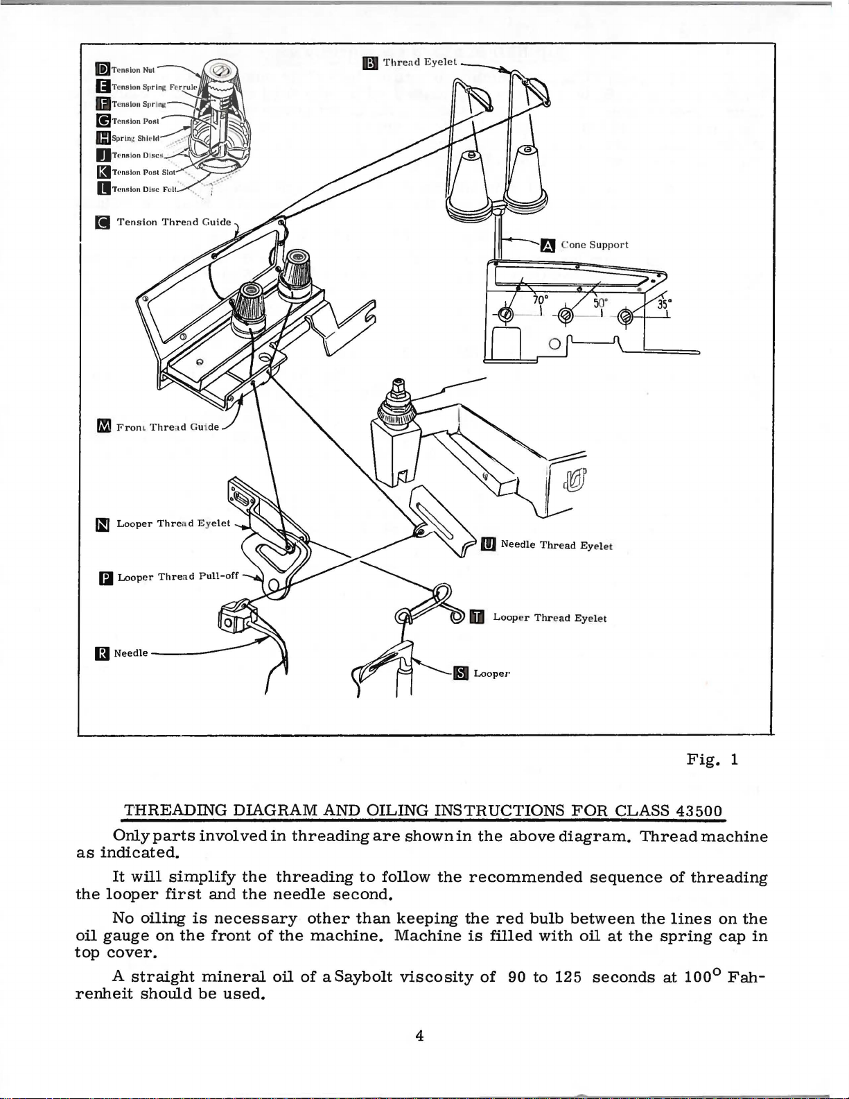
Only
as
indicated.
It
the
looper
No
oil
gauge
top
cover.
Looper
Thre
a d E y
Looper
Thread
Pull-off
THREADING
parts
will
involved
simplify
first
oiling
on
is
the
elet
DIAGRAM
the
and
the
necessary
front
of
AND
in
threading
threading
needle
other
the
machine.
OILING
are
to
second.
than
shown
follow
keeping
Machine
INSTRUCTIONS
in
the
above
the
recommended
the
red
bulb
is
filled
with
FOR
CLASS
diagram.
sequence
between
oil
at
Thread
the
the
spring
Fig.
43500
machine
of
threading
lines
1
on
cap
the
in
A
renheit
straight
should
mineral
be
used.
oil
of
aSaybolt
viscosity
of
4
90
to
125
seconds
at
100°
Fah-
NEEDLE
(Continued)
Class
needle
is
mended
Type
157
sample
on
No.
GJS
To
label.
have
needle,
Selection
should
pass
Success
use
of
needles
reputation
more
than
43500
Type
157
needle.
Round
A.
chromium
100/040. 110/044. 125/049.
needle
or
A
complete
of
proper
freely
in
the
packaged
for
producing
three-quarters
G
machines
GJS.
Below
shank.
double
orders
the
type
order
needle
through
operation
A
use a curved
is
the
round
groove.
plated
promptly
and
size
would
read:
size
needle
under
highest
of
UNION
our
quality
eye
of a century.
blade
description
Description
point.
struck
and
is
available
and
accurately
number
''1.000
is
determined
in
order
SPECIAL
brand
name,
needles
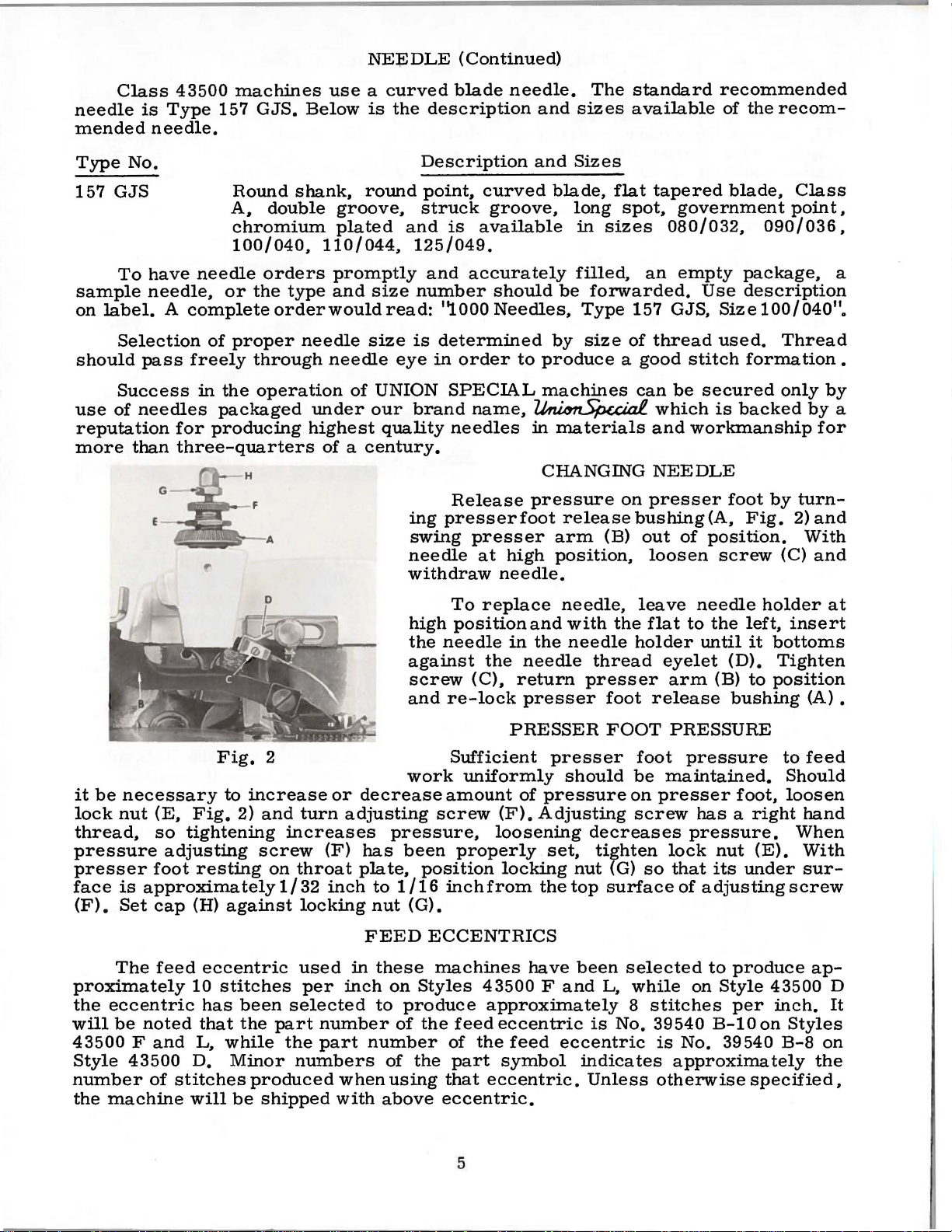
Release
ing
presser
swing
needle
presser
at
withdraw
needle.
and
curved
groove.
should
Needles,
to
~
in
pressure
foot
high
needle.
The
standard
and
sizes
available
Sizes
blade.
be
by
flat
long
in
spot.
sizes
filled,
forwarded.
Type
size
157 GJS,
of
tapered
an
thread
produce a good
machines
can
which
materials
CHANGING
release
arm
(B)
position.
and
NEEDLE
on
presser
bushing
out
loosen
recommended
of
the
blade.
government
080/032.
empty
Use
package.
description
Size
used.
stitch
be
formation
secured
is
backed
workmanship
foot
(A.
Fig.
of
position.
screw
recom-
Class
point.
090/036.
100/040".
Thread
only
by
by
for
by
turn-
2)
and
With
(C)
and
a
•
a
it
be
necessary
lock
nut
(E.
thread.
pressure
presser
face
(F).
so
adjusting
foot
is
approximately
Set
cap
The
feed
proximately
the
eccentric
will
be
noted
43500 F and
Style
number
the
43500
of
machine
stitches
Fig.
to
increase
Fig.
2)
and
tightening
screw
resting
(H)
against
eccentric
10
stitches
has
been
that
the
L.
while
D.
Minor
produced
will
be
shipped
2
turn
increases
on
throat
1/32
locking
used
per
selected
part
the
numbers
or
decrease
adjusting
(F)
has
plate.
inch
nut
FEED
in
inch
number
part
number
when
with
high
the
against
screw
and
work
pressure.
been
position
to
1/16
(G).
these
on
Styles
to
produce
of
the
of
the
using
above
To
replace
position
needle
(C).
re-lock
the
and
in
the
needle
return
presser
PRESSER
Sufficient
uniformly
amount
screw
of
(F).
Adjusting
loosening
properly
locking
inch
from
the
ECCENTRICS
machines
have
43500 F and
approximately
feed
eccentric
of
the
feed
part
that
symbol
eccentric.
eccentric.
needle,
with
needle
thread
presser
presser
should
pressure
decreases
set.
tighten
nut
top
been
L,
is
eccentric
indicates
Unless
leave
the
flat
holder
foot
release
FOOT
foot
be
on
screw
(G)
so
surface
selected
while
8
stitches
No.
39540
is
otherwise
needle
to
the
left.
until
eyelet
arm
(D).
(B)
it
to
bushing
PRESSURE
pressure
maintained.
presser
foot,
has a right
pressure.
lock
that
of
adjusting
to
on
nut
its
under
produce
Style
(E).
per
B-10
No.
39540
approximately
specified,
holder
insert
bottoms
Tighten
position
(A) •
to
feed
Should
loosen
hand
When
With
sur-
screw
43500
inch.
on
Styles
B-8
at
ap-
D
It
on
the
5
The
- 5, - 6, - 7,
-
34,-36,
may
be
ordered
number
11
39540
suffixed
B-10".
following
-8,
-9,-
-
40.
Only
separately.
stitch
FEED
number
ECCENTRICS
feed
eccentrics
(Continued)
are
available
under
10,-11,-12,-13,-14,-15,-16,-18,-20,-22.-24,-26,-28,-30,-32,
one
to
indicate
eccentric
is
supplied
To
order
an
approximately
with
each
eccentric,
the
number
machine.
use
No.
of
stitches
Additional
39540 B with a minor
No.
desired.
39540
B-4,
eccentrics
Example:
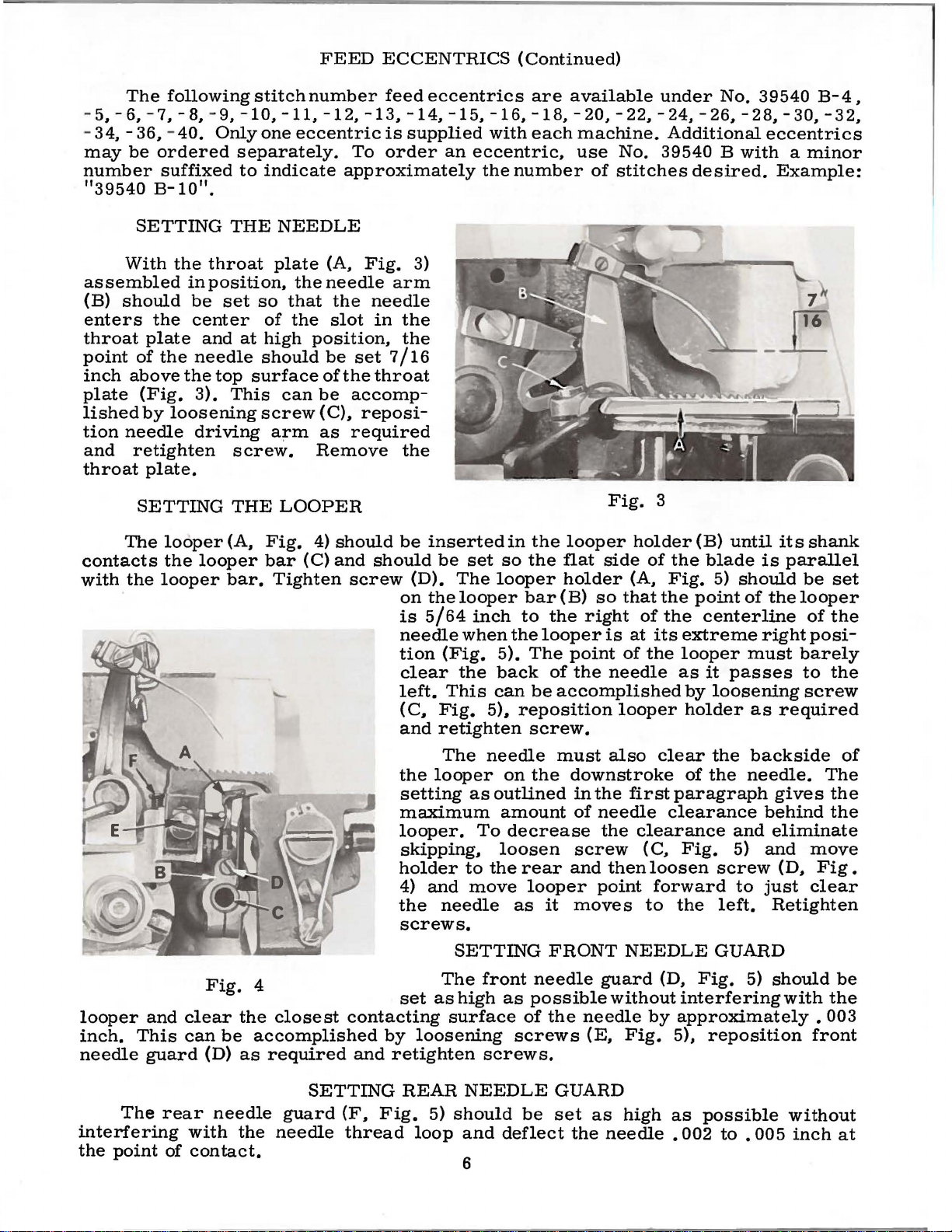
SETTING
With
assembled
(B)
should
enters
throat
point
inch
plate
lished
tion
and
throat
plate
of
above
(Fig.
by
needle
retighten
plate.
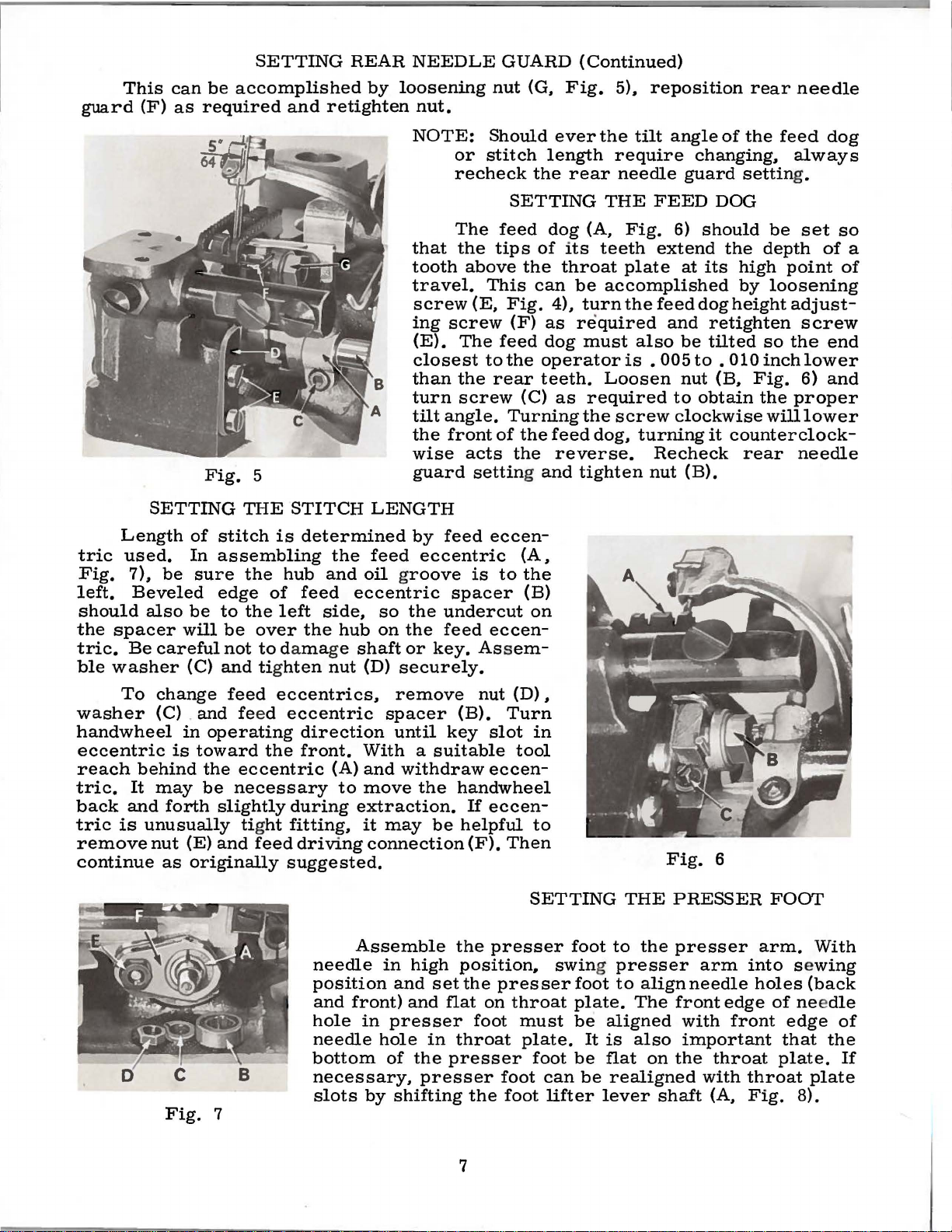
SETTING
The
contacts
with
the
·
the
in
be
the
center
and
the
needle
the
3).
loosening
driving
looper
the
looper
looper
THE
throat
position,
set
so
of
at
high
should
top
surface
This
screw
screw.
THE
(A,
Fig.
bar
bar.
NEEDLE
plate
the
that
the
(A,
needle
the
slot
position,
be
of
can
be
(C),
a;rm
as
Remove
LOOPER
4)
(C)
Tighten
Fig.
needle
in
set
the
throat
accomp-
reposi-
required
should
and
should
screw
3)
arm
the
the
7/
16
the
be
(D).
on
is
needle
tion
clear
left.
(
C,
and
inserted
be
set
The
the
looper
5/64
inch
when
(Fig.
the
This
Fig.
retighten
in
so
the
looper
bar
to
the
5).
The
back
can
5),
reposition
screw.
the
looper
flat
side
holder
(B)
so
the
right
looper
point
of
the
be
accomplished
Fig.
holder
of
(A,
that
of
is
at
of
the
needle
looper
3
the
Fig.
the
the
its
as
(B)
until
blade
5)
point
centerline
extreme
looper
it
passes
by
loosening
holder
its
is
should
of
the
right
must
as
required
shank
parallel
be
set
looper
of
the
posi-
barely
to
the
screw
looper
inch.
needle
and
This
guard
The
interfering
the
point
clear
can
rear
of
Fig.
(D)
needle
with
con
4
the
closest
be
accomplished
as
required
guard
the
needle
tact.
contacting
and
SETTING
(F,
Fig.
thread
The
the
looper
setting
maximum
looper.
skipping,
holder
4)
and
the
needle
screws.
The
set
as
by
loosening
retighten
REAR
5)
loop
needle
on
as
outlined
amount
To
decrease
loosen
to
the
move
as
SETTING
front
high
as
surface
screws
screws.
NEEDLE
should
and
deflect
6
must
the
rear
looper
it
FRONT
needle
possible
of
the
GUARD
be
set
also
downstroke
in
the
first
of
needle
the
clearance
screw
and
moves
then
point
(c.
loosen
forward
to
NEEDLE
guard
without
needle
(E.
as
the
by
Fig.
high
needle • 002
clear
of
the
the
needle.
paragraph
clearance
and
Fig.
5)
screw
to
the
left.
GUARD
(D.
Fig.
5)
interfering
approximately
5),
reposition
as
possible
to • 005
backside
gives
behind
eliminate
and
move
(D,
just
clear
Retighten
should
with
without
inch
of
The
the
the
Fig.
be
the
•
003
front
at
guard
This
(F)
can
as
SETTING
be
accomplished
required
and
REAR
by
retighten
NEEDLE
loosening
nut.
GUARD
nut
(G,
{Continued)
Fig.
5),
reposition
rear
needle
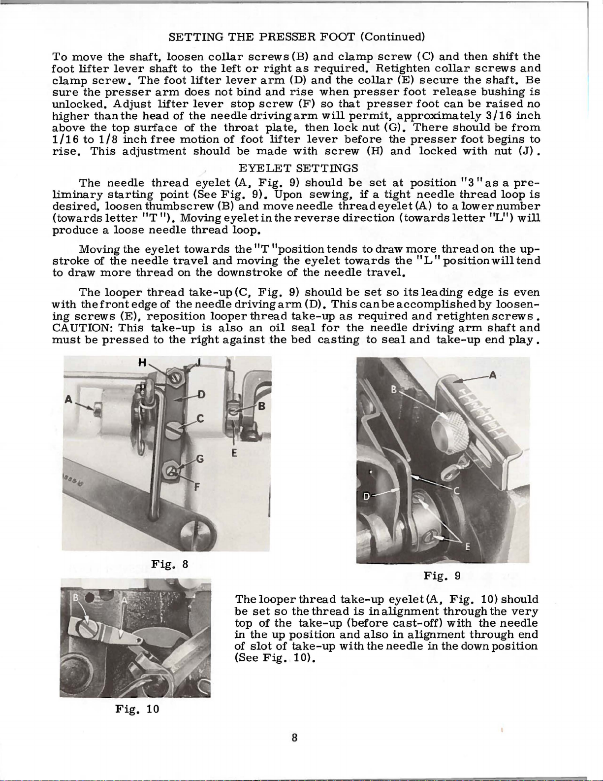
Length
tric
Fig.
left.
should
the
spacer
tric.
ble
washer
SETTING
used.
7),
be
Beveled
also
Be
careful
Fig.
of
stitch
In
assembling
sure
edge
be
to
will
be
not
{C)
and tig
5
THE
the
the
over
STITCH
is
determined
hub
of
feed
left
the
to damage
hten
the
and
oil groove
eccentric
side,
hub
shaft
nut
{D)
NOTE:
that
tooth
travel.
screw
ing
{E).
closest
than
turn
tilt
the
wise
guard
LENGTH
by
feed
so
on
eccentric
the
the
or
key. Ass
securely.
Should
or
stitch
recheck
The
feed
the
tips
above
This
{E,
Fig.
screw
The
feed
to
the
the
rear
screw
angle.
front
Turning
of
acts
setting and
feed
eccen-
is
to
spacer
undercut
feed
eccen-
ever
length
the
rear
SETTING
dog
of
its
the
throat
can
be
4),
turn
{F)
as
required
dog
must
operator
teeth.
{C)
as
the
the
feed
the
reverse.
tighten
{A,
the
{B)
on
em-
the
tilt
angle
require
needle
THE
{A,
teeth
FEED
Fig.
extend
plate
accomplished
the
feed
and
also
is
•
005
Loosen
required
screw
dog,
turning
Recheck
nut
of
the
changing,
guard
settin
DOG
6)
should
the
at
its
high
by
dog
height
retighten
be
tilted
to
.
010
nut
{B,
to
obtain
clockwise
it
counterclock-
rear
{B).
feed
always
g.
be
set
depth
point
loosening
adjust-
screw
so
the
inch
lower
Fig.
the
will
6)
proper
lower
needle
dog
so
of
of
end
and
a
To
change
washer
{C) . and feed
handwheel
eccentric
reach
tric.
back
tric
remove
behind
It
may
and
is
unusually tig
nut
continue
in
operating
is
toward
the
be
forth
{E)
as
originally
Fig.
feed
the
eccentric
necessary
slightly
ht
and
feed
7
eccentrics,
eccentric
direction
front.
{A)
to
during
extraction.
fitting,
driving
suggested.
Assemble
needle
position
and
front)
hole
needle
bottom
necessary,
slots
remove
spacer
until
{B).
key
nut
slot
With a suitable
and
withdraw
move
it
may
the
be
connection
eccen-
handwheel
If
eccen-
helpful
{F).
the
in
in
hole
of
high
and
and
presser
set
in
the
position.
the
flat
on
foot
throat
presser
presser
by
shifting
the
{D)
Turn
in
tool
to
Then
SETTING
presser
presser
throat
must
plate.
foot
foot
foot
,
THE
foot
to
the
swing presser
foot
to
align
plate.
be
be
can
lifter
It
be
The
aligned
is
also
flat
realigned
lever
Fig.
PRESSER
presser
needle
front
with
important
on
the
shaft
6
arm
edge
throat
with
{A,
arm.
into
holes
front
throat
Fig.
FOOT
s e
{back
of nee
edge
that
plate.
plate
8).
With
wing
dle
of
the
If
7
To
move
foot
lifter
clamp
sure
screw.
the
unlocked.
higher
above
1 I
rise.
16
than
the
to
This
the
lever
presser
Adjust
the
top
1 I 8
inch
adjustment
shaft,
shaft
The
arm
lifter
head
surface
free
SETTING
loosen
to
the
foot
lifter
does
lever
of
the
of
the
motion
should
THE
collar
left
lever
not
stop
needle
throat
of
PRESSER
screws
or
arm
bind
screw
driving
foot
be
made
right
and
plate,
lifter
(B)
as
(D)
rise
(F)
arm
then
lever
with
FOOT
and
clamp
required.
and
the
when
so
that
will
permit,
lock
before
screw
(Continued)
screw
Retighten
collar
presser
(E)
foot
presser
approximately
nut
(G).
the
(H)
and
(C)
and
collar
secure
release
foot
There
presser
locked
then
the
can
should
foot
with
shift
screws
shaft.
bushing
be
raised
3116
begins
be
nut
the
and
Be
is
no
inch
from
to
(J)
•
The
needle
liminary
desired,
starting
loosen
(towardsletter
produce a loose
Moving
stroke
to
draw
The
with
ing
the
screws
CAUTION:
must
be
of
the
more
looper
front
(E),
This
pressed
the
needle
edge
thread
point
thumbscrew
"T").
Movingeyeletinthereversedirection
needle
eyelet
towards
travel
thread
on
thread
of
the
reposition
take-up
to
the
eyelet
(See
Fig.
(B)
thread
and
the
downstroke
take-up
needle
looper
is
also
right
against
EYELET
(A,
Fig.
9).
and
move
loop.
the
"T
moving
(C,
Fig.
driving
thread
an
SETTINGS
9)
should
Upon
sewing,
needle
"position
the
eyelet
of
the
9)
should
arm
(D).
take-up
oil
seal
the
bed
be
thread
tends
towards
needle
be
This
as
for
the
casting
set
at
if a tight
eyelet
to
draw
the
travel.
set
so
can
be
accomplished
required
needle
to
seal
position
needle
(A)
"3
thread
to a lower
(towardsletter
more
its
and
and
thread
"L"
position
leading
retighten
driving
take-up
arm
"as a pre-
loop
number
"L")
on
the
will
edge
by
is
loosen-
screws.
shaft
end
play.
is
will
up-
tend
even
and
Fig.
Fig.
10
8
The
be
top
in
the
of
slot
(See
looper
set
so
of
the
up
of
Fig.
thread
the
thread
take-up
position
take-up
10).
take-up
is
(before
and
with
8
eyelet
in
alignment
cast-off)
also
in
the
needle
Fig.
(A,
9
Fig.
through
with
alignment
in
the
10)
the
through
down
should
the
very
needle
end
position

EYELET
SETTING
(Continued)
Looper
for a preliminary
eyelet
stitch,
downward
the
pulled
CAUTION:
locking
screw
point
assembled
the
the
thread
as
move
The
thread.
up
screw
(D)
In
assembly,
of
rear.
stud
to
should
required
the
acts
looper
stitch
assembled.
removing
Stud
the
The
When
to
the
screw
the
(B)
locking
cast-off
setting.
and
looper
reverse.
thread
needle
and
still
removing
and
the
cloth
all
machine
(D)
retighten
thread
tension
thread
not
lift
upcloth
play
with
screw
so
when
Loosen
take-up
THREAD
should
tension
pucker
CLOTH
the
plate
and
yet
the
(B)
that
only
screw.
cloth
plate
screw
turn
flat
is
the
the
point
screw
Should
eyelet
TENSIONS
be
set
should
the
material.
PLATE
plate
with
and
in
and
''V"
tightened
cloth
of
the
needle
(B),
REMOVAL
(A,
the
the
plate
reposition
upward,
as
light
be
set
Fig.
the
cloth
cloth
cloth
slot
of
securely
will
more
is
at
the
top
looper
thread
to
cast
as
possible
to
produce a reasonably
11)
loosen
plate
plate
plate.
the
cloth
which
turn
stud
when
be
off
the
stud
(C)
are
The
cloth
plate
collapses
opening
later,
and
cloth
tightened
stud
of
the
thread
required
moving
still
plate
and
cloth
plate
(C)
the
or
looper
take-up
in
the
control
well
stud
plate
to
the
is
then
towards
body
closing
it
of
•
Fig.
11
9

10

MAIN
FRAME,
MISCELLANEOUS
COVERS,
PLATES
AND
EYELETS
Ref.
No.
1
2
3
4
5
6
7
8
9
10
11
12
13
14
15
16
17
18
19
20
21
22
23
24
25
26
27
28
29
30
31
32
33
34
35
36
37
38
38A
39
40
41
42
43
44
45
46
47
48
49
50
51
52
53
54
55
56
57
58
Part
No.
43564
22838
39557
43557
39556
39557
39557
39557
39557
39557
39582
50-795
22562
39582
51-103
39582
39582
39582
22541
39582
667
22571
39594
22569
80
43579
43568
22569
39501
22569
22565
660-234
43594
86
41071
39582
22657
43501
43501
90
39532
25
22824
39594
39594
22513
43568
39593
660-243
22894
39582
22653
39593
93
395
39582
22569
39582
39595
22586
A
A
F
c
E
B
AH
A
w
AG
v
AF
AE
D-8
E
R
D
A
D
K
F
X
G
D
D-12
A
A
s
G
H
B
B
H
AE
F
D-4
D
c
y
XD
R
Blk.
Blk,
Description
Adjustable
Thumbscrew,
control
Presser
Presser
Presser
Presser
Lock
Presser
Presser
Presser
Top
Cover-------------------------Presser
Screw,
Oil
Hinge
Hinge
Spring,
Oil
Screw,
Top
Cover
Dowel
Magnetic
Oil
Collector
Screw,
Screw,
Supplementary
Looper
Screw,
Cloth
Screw,
Screw,
Coupling,
tube---------------------------------------
Needle
Screw,
Nut,
for
Feed
Screw,
Cloth
installation--------------------------------Cloth
Screw,
Cloth
Screw,
Screw,
Oil
Filter
Oil
Strainer--------------------------------Screw,
Looper
Oil
Sight
Oil
Gauge
Screw,
Bottom
Screw, for
extension
Oil
Gau
Oil
Gau
ottom
B
Screw,
ottom
B
Mounting Isolator,
Screw
, f
Needle
eyelet
Spring
Spring
Foot
Spring
Nut,
for
Spring
Spring
Spring
for
Guard
Pin
Bracket
for
Filler
for
top
Gasket----------------------------
Pin,
for
Oil
for
oil
for
supplementary
Thr
ea d
for
looper
Plate
Stud------------------------------
for
cloth
for
feed adj
for
Driving Arm
for
feed
feed
Mechanism
for
cloth
Plate,
Plate,
Plate
for
for
for
cloth
Latch Spr
for
mounting attachment
for
oil
Screen-----------------------------
for
looper
Thread Fra
Gau
ge
Seal
for
looper
Cover and
bottom
----------------------------------
ge
Indicator---------------------------
ge
Float------------------------------
Cover Gas
for
bottom
Cover--------------------------------
or
bottom
Thread
for
adjustable
- -
---------------------------Plunger----------------------Spacer------------------------
Release
------------------------------
plunger
Plunger
Plunger
Plunger
Foot
Release
hin
ge
-------------------------------
------------------------
---------------------------
oil
filler
Cover
cover
top
cover----------------------
Drain
Plate---------------------------
mechanism
Plug
collector
Cloth
Take-up
thread
plate
usting
needle
Bushing
mechanism
Cover-----------------------
plate
semi
non-submerged
plate
filt
er
screen
thread
me
------------------------------
Ring --------------------------
lever
Base
cover
ket-------------------------
cover----------------------
rubber---------------------
cover----------------------
Control
needle
Bushing----------------adjusting
Adjusting
Lock
Nut--------------
Cap
Nut---------------
Bushing
bracket------------------
cover----------------
-------------------------
-------------------------
----------------------
plate-------
cloth
Plate
--------------------
Eyelet
take-up
stud-------------------
pin------------------
driving
------------------------
or
latch
ing
Eyelet------------------
arm
Oil
cover--------------
cover
fully-submerged
spring-------------
----------------------
-------------------
frame
shaft------------------
Plate
Extension
and base
Eyelet
screw----------
Screw--------
Guide
plate-----------
---------------eyelet
bushing
Tube----------
screw----------
installation-----
---------------
eyelet
plate
thread
-
-
----------
--------
---------
--------
-------
-------Pin
-
oil
------
---
Amt.
Req.
1
1
1
2
1
1
1
1
1
1
1
1
1
1
1
1
1
1
8
1
2
1
1
1
1
1
1
1
1
- 1
1
1
1
1
1
1
1
1
1
2
1
2
2
1
1
1
1
1
1
2
1
2
1
1
1
14
1
4
1
11

A-NEEDLE
B-PIVOT
C-LOOPER
DRIVE
SHAFT
DRI
BEARING
BEARING
VE BE
ARING
12

CRANKSHAFT
MECHANISM
AND
BUSHINGS
Ref.
No.
--
1
2
3
4
5
6
7
8
9
10
11
12
13
14
15
16
17
18
19
20
21
22
23
24
25
26
27
28
29
30
31
32
33
34
35
36
37
38
39
40
41
42
43
44
45
46
47
48
49
50
Part
No.
22569
660-219
43534
39590
43555
39573
39555 N
39573
43552
39552
39644 c
39590 T
39644
39690
22894
39591
39591 L
39590 J
39590
39590 R
39590 s
39590 H
22541 A
39521 G
39521 D
22769 B
29477
C0-67
39541 A
29477 MD
22768
22596
22587
39690 A
39690 B
39590 N
39691
22747 B
39591 K
39594 N
E
A
K
AA
B
p
s
666-94
660-443
D
H
G
660-268
95
JV
258
40-46
E
30-106
51-228
c
H
M
97 A
u
87
E
Elk.
Elk.
Description
Screw.
Roll
Feed
Arm
Crankshaft
Foot
Pivot
Foot
Pivot
Needle
Needle
Looper
Crankshaft
Looper
Oil
Crankshaft
"O"
Screw.
Chamber
Char.nber
ThrustWasher--------------------------------Crankshaft
Crankshaft
Ball
Spacer
Crankshaft
Screw.
Pulley
Pulley
Screw.
Crankshaft
Stud.
Crankshaft
Stud.
Crankshaft
Screw.
Crankshaft
Screw.
Oil
for
feed
bar
thrust
Pin.
for
feed
bar
Bar
Thrust
Bushing.
Bushing,
Lifter
Shaft
Lifter
Shaft
Wick
Ring.
Bearing
Screw.
Nut.
Washer.
Cork
Wood
Feed
Vent
Needle
RodAsser.nbly-----------------------------
for
Screw.
for
Splasher-----------------------------------
Shaft
Bushing,
Shaft
Bushing.
Arm
Arm
Drive
Bushing.
Drive
and
Bearing.
for
for
fan
Cooling
Cooling
Ball
Ball
Collar----------------------------------
Ball
for
ball
---------------------------------------for
Cap
------------------------------------
for
pulley
and
for
Plug.
Plug
Drive
Plug.
Driving
Screw.
rodpin-------------------------------Screw.
Screw.
rod-----------------------------------
crankshaft
Split
for
split
Counterweight.
for
counterweights
Counterweight.
for
oil
Washer
left
---------------------------left------------------------
Bushing.
left------------------------
Bushing.
right-----------------------
Bushing.
Bushing.
Shaft
Shaft
Spring
crankshaft
Stop
crankshaft
for
---------------------------------
for
for
bearing--------------------------
splasher
Bushing.
inner
Bushing.
---------------------------inner
collar---------------------------
Fan
Fan---------------------------
Bearing
Bearing
Collar------------------------
Bearing
bearing
pulley---------------------------
cap---------------------------
Needle
crankshaft----------------------
for
crankshaft
Eccentric
for
crankshaft
Arr.n
for
needle
needle
needle
bearing---------------------
Bearing------------------------
split
bearing---------------------
washer
thrust
left----------------------right----------------------
Collar--------------------
Driving
-------------------------
-------------------------
washer
and
left------------------right
right
left-------------------
left-----------------
right
bearing.
Housing-----------------
------------------------
Retainer
housing------------------
Key
Crank
driving
driving
driving
right-----------------
---------------------left
---------------
Needle
-----------------
---------------
----------------inner
Plate-----------
Crank-------------
-------------------
-------------------
------------------and
Connecting
arr.n
arm
arr.n
------------------
------------Driving
right-----
connecting
crank
connecting
------
Amt.
Req.
3
2
1
1
1
1
1
1
1
1
1
1
1
1
1
1
2
1
1
1
1
1
1
1
1
3
1
2
1
1
1
1
1
1
1
1
1
1
1
1
2
1
1
2
1
1
4
1
1.
1
13

14
42
~
43
~

NEEDLE
GUARD.
AND
NEEDLE
FEED
DRIVE
DOGS.
MECHANISM
FEED
MECHANISM
Ref.
No.
1
2
3
4
5
6
7
8
9
10
11
12
13
14
15
16
17
18
19
20
21
22
23
24
25
26
27
28
28A
28B
29
30
31
32
33
34
35
36
37
38
39
40
41
42
43
Part
No.
39536
39536
22565
39535
39535
39535
53634
22569
43534
43535
53634
22569
538
39536
39538
258 A
43534
43525
43525
22863
43534
39540
39540
39536
39540
40-46
258
93
9205
56305
43505
87 u
43552
43552
28 c
22596
157
43568
88
660-207
39552
39543
22782
39552
39594
87
K
E
F
c
J
c
D
c
B
J
c
B
A
c
B
B-10
B-8
AF
K
A
E
A
E
GJS
c
y
A
R
N
u
Description
Feed
Nut.
Screw.
Feed
Feed
Main
Washer.
Screw.
Main
Main
Washer.
Screw.
Feed
Feed
Feed
Nut.
Stabilizing
Clamp
Needle
Tilting
Feed
Main
Main
Feed
Feed
Washer.
Nut.
Screw.
Feed
Feed
Feed
Screw.
Needle
Needle
Needle-------------------------------------------
Looper
11011
Take-up
Needle
Needle
Oil
Screw.
Bar
Driving
for
feed
for
feed
Adjusting
Bar
Guide
Feed
Feed
Feed
Dog
Bar
Lift
for
Dog
Feed
Fand L -----------------------------------------
Feed
Bar
Eccentric
for
Dog.
Dog.
Dog.
Screw.
Screw.
Screw.
Ring.
Screw.
Splasher
Bar
for
feed
for
left
Bar-----------------------------------Bar
for
feed
for
right
Height
Driving
Block-----------------------------------
feed
Washer.
Washer.
Guard.
Screw.
Holder----------------------------------
Driving
Driving
Driving
for
feed
feed
for
feed
16
16
12
for
needle
Driving
Driving
for
for
Thread
for
for
Lever
Lever
for
Lever
--------------------------------------
for
oil
Connection
bar
driving
adjusting
Pin--------------------------------
Block
Guide.
main
Guide.
main
Adjusting
dog
for
rear
for
Spacer-----------------------------
driving
dog
teeth
teeth
teeth
Arm
Arm.
needle----------------------------needle
Take-up----------------------------
looper
looper
Thrust
Drive
needle
Drive
splasher
----------------------------left
bar
guide
feed
right------------------------
bar
guide
feed
Stud-----------------------------
holder
for
feed
rear
-------------------------------
feed
dog
Eccentric.
Eccentric.
Connection-----------------------
driving
eccentric
-------------------------------
per
inch.
per
inch.
per
inch.
driving
Thread
marked
driving
thread
thread
Washer----------------------
Shaft
drive
Shaft
----------------------------
Bushing
stud
----------------------
pin-----------------------
------------------------screw-------------------
bar
guide
screw-------------------
bar
Screw
--------------------------dog
needle
holder
for
for
eccentric------------------
for
for
for
arm
Thrust
--------------------------
thread
Ej>;elet------------------
'H
arm------------------
take-up
take-up
shaft
-----------------
guide----------------
-------------------
holder--------------
guard---------------
-----------------Styles
Style
--------------------Style
Style
Style
11
------------------
Collar
thrust
---------------
43500
43500 D ------
43500 F ------43500 L ------43500
eyelet
---------------
----------------
-------------
D-------
---------
collar-------
Amt.
Req.
1
1
1
1
1
1
2
2
1
1
2
2
1
1
1
1
1
1
1
1
1
1
1
1
1
1
1
1
1
1
1
1
1
1
1
1
1
1
2
1
1
1
1
1
1
1
15

16

THROAT
PLATE,
THROAT
PLATE
SUPPORT,
LOOPER
AND
LOOPER
DRIVE
MECHANISM
Ref.
No.
4
10
11
12
13
14
15
16
17
18
19
20
21
22
23
24
25
26
27
28
29
30
31
32
33
34
35
36
36A
37
37A
37B
37C
38
39
40
41
42
43
44
45
46
47
48
49
50
51
52
53
54
55
56
57
58
59
60
1
2
3
5
6
7
8
SA
BB
9
Part
No.
43580
43
578 B
22784 E
660-334
43580
22656
87
43524
43524
0112
22564 D
43508
22503
39543 E
39644 L
39644
22775
22781
41336
43544
A
98
43544
39573 A
39573 E
55235 D
6042 A
55235 E
39673
22587 E
39644 M
22565
22565 L
v
39644
39644 p
98
39644 E
J-4
226 53
43578
43578
43503
43503
43503
22542
43578
22585
4352
14077
22892 B
22653
39580 F
39644 A
39543
39644
39644 N
39543
22562 A
39644
22729 D
22729 E
39644
39644
39644 X
22894 c
c
c
B
A
c
25
A
5
B-12
p
660-206
1VI
u
R-2
R-5
538
482
c
A
A-6
A
F
w
c
c
Description
Throat
Fabric
Screw,
Retaining Rin
Throat
Screw,
Screw,
Throat
Throat
Throat
Screw, for
Looper,
Screw,
Cam
Cam
Looper
Screw,
Screw,
Looper
Thrust
Looper
Washer,
Pivot
Looper
Looper
Set
Spot
Bushing
Thrust
Looper
Fabric
Fabric Gua
Edge
Ed
Ed
Sc
Scr
Pivot Shaf
Screw,
Needle
Nut, f
Locking Screw, for
Screw,
Wa
Looper Bar
Thrust Was
Looper
Looper
11
0'
Clamp
Looper
Shim,
Shim,
Ball
Screw,
Looper
Plate
Support
Guard
for
Plate
for
for
Plate,
Plate,
Plate,
for
Follower
Follower-------------------------------------------
Bar
for
for
Avoid
Collar,
Screw,
Avoid
Shaft
Locking
Washer, for
Nut,
Avoid
Screw,
Avoid
Screw,
Screw,
Collar
Screw,
Holder----------------------------------------------------
Screw,
Guard,
Guide,
ge
Guide
ge
Guide,
rew,
for
ew,
for fabric
for
Guard,
or
for throat plate support bra
sher----------------------------------------------------------
Drive Lever----------------------------------------------Drive Lever Shaf
Rin
g, for
Collar-----------------------------------------------------
Screw,
Drive
Screw,
Screw,
for
for
Joint
for
Drive
Screw,
Position
fabric
g,
Support
throat
throat
for
for
for
looper-------------------------------------------------
marked
cam
Locking Clamp--------------------------------------
Sleeve-----------------------------------------------looper
looper
Link
for
Pivot Shaft------------------------------------------
for
pivot
Drive
Stud,
for
driving lever-----------------------------------------
Connecting Rod
for
Link------------------------------------------------
for
bushing and
for
and
Cam
----------------------------------------------------
for
for
for
rd,
for Sty
for Styles 43500 F a
Bracket, for
for
No. 43503 A
t,
for fabr
front needl
front-----------------------------------------------
locking scr
------------------------------------------------------
her, for
looper
for
Lever
for
connecting
for
connecting
ball
joint
ball
joint
Guide
ball
joint guide
Lever
for
collar-----------------------
Bracket
ing Fing
guard pos
for
pivot
Plate-----------------------------------------
plate
support plate-------------------------------plate-------------------------------------------Style
43500 F -----------------Style
43500 L -----------------------------------Style
43500 D ------------------------------------
11
"CT
follower
for
thrust
connecting rod-------------------------------------
bushing an
thrust
looper
Sty
clamp
Fork
--------------------------------------------
avoid
avoid
Pin
--------------------------------------------
pivot
collar---------------------------------------
shaft--------------------------------------------
Lever
for
driving lever---------------------------------
driving lev
Guide--------------------------------------------
collar---------------------------------------
holder--------------------------------------
Style
le
le 43500
gua
rd and
ic
gua
e g
ew
--------------------------------------------
cloth
looper bar-------------------------------------
driv
collar---------------------------------------
Connecting Rod
guide
guide fork,
------------
Shaft
-------------------------------------er
-----------------------------------
itioning
shaft -------------------------------------
locking clamp------------------------------
link--------------------------------------link
pin------------------------------------
shaft--------------------------------------
------------------------------------------er
cam guide-------------------------------
d ca m g
43500
43500
Style 435
D--------------------------------------
on Style
edge
rd---------------------------------------
uard--------------------------------------
pla
te lat
t------------------------------------------
e lever
rod--------------------------------
rod-------------------------------------
fork, . 002 inch
fork-----
Collar
finger---------------------------
-------------------------------------
--------------------------------------
uide------------------------------
F-----------------------------------L--------------------------------
nd
L-------------------------------
00 D ------------------------------
43500
guide
shaft
. 00 5
-----------------------------------
D----------
No.
ch spring--------------------------
cket-----------------------------
------------------------------
--------------------------------
thick-----------
inch thick---------------as
-
-------------------------------..
-------------------------------
-
-----------------
-
--------
-
-----------------
43503 C -------------------
-
---
as
-
---------------------
Amt.
-
---
-
----
required
required
Req.
1
1
2
1
1
2
2
1
1
1
1
1
1
1
1
1
1
1
1
1
2
1
1
1
1
1
1
1
2
1
1
1
1
1
2
1
1
1
1
1
1
1
1
2
1
2
1
1
1
2
2
1
2
1
1
2
1
1
1
2
2
1
2
1
2
17

18

PRESSER
FEET,
FOOT
LIFTER
PARTS
AND
THREAD
TENSION
PARTS
Ref.
No.
1
2
3
4
5
6
7
8
9
10
11
12
13
14
15
16
17
18
19
20
21
22
23
24
25
26
27
28
29
30
31
32
33
34
35
36
37
38
39
40
41
42
43
44
45
46
47
48
49
50
51
Part
No.
43556
22791 H
258 A
43555
12865
88
39555 c
627
12538
22597 E
39555 F
660-142
39555 D
39555 B
39855
43520
604
56330
61430
43530
22799 G
43530
56330 B
43530
22566 B
43520
43530
22799 H
43530
A
51330 w
43530
43556
F
A
22585 B
39592
39592
39592
39592
AB
AC
AK
AR-2
43592-8
39592
39592
39592
39592
39592
8372
39592
AJ
AD
AF
AL
AG-3
A
AM
22847 B
22806
A
652-16
39592
43520
AH
B
43530
43530
G
22799 H
A
AR
BT
D
B
c
Description
Presser
Screw,
Nut,
Foot
Thrust
Foot
Foot
Cotter
Foot
Foot
Foot
Presser
Arm
for
for
presser
Lifter
Collar,
Screw,
Lifter
Screw,
Lock
Nut,
Screw,
Lifter
Pin,
Lifter
Lifter
Lifter
Foot
Screw,
Spring,
Spring,
-----------------------------------
presser
Lever
for
Lever
for
for
Lever
for
Intermediate
Lever
Lever
Assembly,
for
for
for
arm--------------------------
arm
screw----------------------
Shaft
for
thrust
--------------------------
foot
lifter
collar----------------------
Arm---------------------------
lever
for
lever
arm------------------------
lever
arm
arm------------------------
Connecting
connecting
link--------------------
Lever
Spring-------------------------
------------------------------for
spring
yielding
chaining
--------------------------section-------------------
section
PresserFootShank-------------------------Hinge
Presser
Chaining
Yielding
Screw,
Presser
for
Foot
Screw,
Foot
for
presser
Bottom
------------------------
Section-----------------------------
Section-----------------------------
foot
lifter
Assembly,
lever-----------------------
for
PresserFootShank-------------------------Hinge
Presser
Spring,
Chaining
Chain
Screw,
Looper
Needle
Tension
Looper
Needle
Spring
Thread
Tension
Thread
Tension
Washer,
Tension
Screw,
Screw,
Washer,
Shoulder
Presser
Presser
Presser
Hinge
Screw,
Foot
for
for
presser
Bottom
chaining
------------------------
section
Section-----------------------------
Cutting
for
Tension
Tension
Spring
Tension
Tension
Knife------------------------------
chain
cutting
Nut,
Nut,
red
Ferrule
knife
blue
------------------------
-------------------------
--------------------------
Spring------------
Spring
---------------------------
Shield------------------------------------
Tension
Disc
Tension
Post
for
Post
for
tension
for
tension
for
Nut,
Foot
Screw
Disc-----------------------------
Felt
thread
-------------------------------
Post
Mounting
---------------------------Bracket
tension
post-------------------
Bar--------------------------------
post
mounting
post
mounting
bracket
for
Assembly,
Foot
Foot
screw----------
thread
tension
for
Style
Shank-------------------------Bottom,
marked
--------------------------------
19
lever
shaft-----------
--------------------Link
----------------
-------------------
Style
43500 L ---------
------------------
foot
bottom----------
Style
43500 F ---------
foot
bottom----------
------------------
and
presser
....
--------------
foot
-------------------
bracket
bracket
----------
----------
-
------------
post--------------
43500
"BX
D---------
11
----------
-----
Amt.
Req.
1
1
1
1
1
2
1
1
2
2
1
2
1
1
1
1
1
1
2
1
1
1
1
1
1
1
1
1
1
1
1
1
1
1
1
2
1
1
2
4
2
2
1
2
1
1
1
2
2
1
1
1
1

20
b
~
29

THREAD
STAND
AND
ACCESSORIES
Ref.
No.
1
2
3
4
5
6
7
8
9
10
11
12
13
14
15
16
17
18
19
20
21
*22
23
24
25
26
27
28
29 WR64
30
Part
No.
21101
SC303
22810
21114
22651
21114
258 A
21114
652-16
21114
21104
21114
22651
21104
21114
22651
21104
652-16
21114
21114
22651
21225-5/64
660-272
660-264
421
21388
21207
21388
WR70
28604
660-458
H-2
T
CD-4
S-2
w
v
H-2
CD-4
B-24
D-2
CD-5
H
u
A
CD-4
D-34
w
A
AU
R
Description
Thread
Looper
Thread
11
"S
Foot
Wrench,
Screwdriver.
long------------------------------------------
Socket
feed
Wrench.
Wrench.
Container
Dust
Stand,
Wood
Clamp
Lead
Screw----------------------------------
Thread
Nut---------------------------------------Spool
Washer-----------------------------------Spool
Pad,
Thread
Thread
Thread
Nut----------------------------------------
Washer------------------------------------
Lead
Thread
Hook.
for
Screw
Screw
Screw
Gauge,
Tweezers-------------------------------
Lifter
curved
Wrench.
eccentric---------------------------------
3/32
7/64
Cover
complete
Screw,
Screw-------------------------------
Eyelet
Stand
Seat
Pin
Stand
Stand
Stand
Eyelet
Stand
for
Treadle
of
Oil.
(not
for
Socket
Lead
Disc-----------------------------
----------------------------------
thread
Eyelet
--------------------------------Rod---------------------------
Spool
---------------------------------
Ball
Base--------------------------
--------------------------------5/64
treadle
double
1/8
inch
for
inch
hexagonal---------------------
inch
hexagonal---------------------
16
shown)--------------------------
-------------------------
thread
Eyelet
cone------------------------
Split
inch------------------------
chain----------------------
Chain.
end,
diameter.
3/8
inch
fluid
stand
Ball
---------------------
-------------------
Support
Seat
Support--------------
Socket-----------------
34
inches
9/32
hexagonal
ounces
base-----------
-----------------
long---------
inch
opening-----
4
3/16
(not
inches
nut
holding
shown)-------
Amt.
Req.
1
3
1
1
1
1
4
2
2
2
2
1
1
1
1
2
1
1
2
1
1
1
1
2
1
1
1
1
1
1
1
1
*
Available
as
extra
send
and
charge
item.
21

NUMERICAL
INDEX
OF
PARTS
Part
No.
25
c
..........
25
s
..........
28
c
..........
30-106
40-46
50-575
51-103
51-228
WR64
C0-67 E ........•.
WR70
80
86 X ..••••••••
87
87
88
90
93
9 5 • • • • • • • • • • • •
97
98
0112
157
258
258 A ..•••..•..
SC303
421
482
538
604
62 7 • • • • • • • • • • • •
652-16
660-142
660-206
660-207
660-219 E ••••••
660-234
660-243
660-264
660-268
660-272
660-334
660-443
660-458
666-94
667
6042
8372 A ..••••••..
Blk
•...••..•
Blk
Blk
Blk
•••••••••...
..•.....•.•.
. . • • • . . . • • . • 11
.....••••...
u
..........
••..•.•.•.•.
• • . • • • • • • • • .
A
••••••••..
A • • • • • • • • • •
. . . • • • . . . . • .
• . . . • • • . . • • .
GJS
..••••..
...•.•••....
....••••••••
D-34
c
.•••.••••...
• • • • • • • . • • • .
D-8
A . • • • . • • . . •
••••..•
..........
•••••••••
.•.•••••
• • • • • • • .
.•••••••
.••••.••
. • . • • • • .
•••••.•.
••••••..
••••.••.
••.•.••.
••.•••••
•.••••••
•••••••••
• • • • • . • •
••...
•...•
..•..
...•.
Page
No.
17
11
15
13
13,
15
11
11
13
21
13
21
11
17
13,
15
15,
19
11
15
13
13
17
17
15
13,
15
15, 19,
21
21
17
15,17
19
19
19,
21
19
17
15
13
11
11
21
13
21
17
13
21
13
11
17
19
Part
No.
9 20 5 E • • • • • • . • • • .
12538
12865
14
21101
21104
21104 H ••..•.••...
21104
21114
21114 A .••.•.•..•.
21114
21114
21114
21114 T •••....•...
21114
21114
21207 A •.•••••..•.
21225-5/64
21388
21388
22
22513 B ••••••••••.
22541
22541 A •.••••.•...
21
22
22562A
22
22565C
22565
22565 L •.•••.•.••.
225-66 B
22569
22569 B ...........
22569 D .••••••.•••
22571 E •.•••.•.•••
22585
22585 B ...........
22586 R ••••.•••••.
22 58 7 E • • • • • • • • • • •
22587 M •••••.••••.
22596 E •••••••.•••
22596 H ...........
22597 E .••••••••••
22651
22651
22653
22
2 2 6
..•••••..•...
•••••.•••.•..
07 7 • • • • . . . • • . . . •
H-2
B-24
v
...........
.•••••••..•..
D-2
H-2
S-2
u
...........
w
...........
w
...........
AU
.•.•••....
50 3 F . . . . . . . . . . .
•.•••..•.•..•
542
• • • • • • • • • • . . .
...••••••.•
564
D • . • • • • • • • • •
•••••••••••
F
•.•••.••.••
••.•••••..•
.............
••••••.•••..•
CD-4
CD-5
B-12
653
D-4
53 J -4.
Page
No.
15
19
19
17
.........
•••...•.
•.•.•••.•
.•••••.••
•••.••••.
•...•...
21
21
21
21
21
21
21
21
21
21
21
21
21
21
21
21
17
11
11
13
17
11,17
17
17
11,
17
19
11,
15
11
11
17
19
11
17
13
15
13
19
•.•••••.
•••...••
........
••.••••••
• • • • • . . • . 1 7
21
21
17
11
15
13,
15
Part
No.
22656
22657
22729 D ..........
22729 E •.•••••.•.
22747 B •••.•.....
22768
22769 B •..••••..•
22775
22781
227
22784 E ..........
22791 H .••••..•..
22799 G •••.••••••
22799 H ..........
22806
22810
22824
228 38 • • • . • • • . • . • .
22847 B ..•..••...
22863
22892 B ..........
22894C
22894D
22894
28604 R .•.••..•..
29477
29477
39501
39521 D ..........
39521 G •••••••...
39532 A ..........
39535
39535
39535 J •.••••••.•
39536 E •••••••.••
39536 J ••••••••••
39536
39536
39538
39540
39540
39540
39541 A ••••..•.•.
39543 E ..........
39543 M •..•••••.•
39543
39543
39552
A-6
•...••••
D-12
c
• • • • • • • • • • • •
..••..•.•.•.
82 A • • • • . • • . • .
A
............
............
c
AE
JV
MD
K
.••..•••••..
c
K
AF
•••••••.••.•
B-8
B-10
K
p
y
c
.•.•...
..........
••••••••••
..........
..........
..........
..•••••.•
.........
••....•..
•••••••.••
..........
••••••••••
•••••••.•
••••••••
••..••.
..........
..••......
..........
..........
Page
No.
17
11
17
17
13
13
13
17
17
15
17
19
19
19
19
21
11
11
19
15
17
17
13
11
21
13
13
11
13
13
11
15
15
15
15
15
15
15
15
15
15
15
13
17
17
17
15
15
22

NUMERICAL
INDEX
OF
PARTS
Part
No.
39552
39552
39555 B •••.••.•••.
39555
39555 D •••••••.•••
39555 F •.•••.•••..
39555 N •.•.•.•••••
39556 A •.•.••••.••
39557
39557 A •..••••••.•
39557 B •.•••.•.•••
39557
39557 E •••••.••.•.
39557 F •.•.••.••••
39573 A •.•.••.•••.
39573 E ••.•••.•..•
39573 K •.•••••••••
39573
39580 F •.•••.•••••
39582 D ...........
39582 F •.•••••..••
39582
39582
39582
39582
39582
39582
39582
39582
39590
39590 G •.•.•.••.••
39590 H .•••••.••••
39590
39590 N •.••.•.••••
39
39590
39590 T •••••••.•••
39591 H •••••.••.••
39591 K ...........
39591 L •••••••••.•
39592
39592
39592
39592
39592
39592
39592
39
p
...........
R
...........
c
...........
. . . . . . . . . . . . .
c
...........
AA
..........
v
...........
w
...........
y
...........
AE
...•.•.••.
AF
••..•.••••
AG
..•.••••••
AH
..•••..•.•
XD
.•••.•••••
. . . . . . . . . . . . .
J
. . . . . . . . . . .
590
R
...........
s
. . . . . . . . . . .
AB
..........
AC
•••...•.•.
AD
•••••.••.•
AF
••••••••••
AG-3
AH
••••.••••.
AJ
•••••.••••
592
AK
•••.••••••
•••.••••
Pa
ge
No. No.
13
15
19
19
19
19
13
11
11
11
11
11
11
11
17
17
13
13
17
11
11
11
11
11
11
11
11
11
11
13
13
13
13
13
13
13
13
13
13
13
19
19
19
19
19
19
19
19
Pa
39592
39592
39592
39593
39593
39593
39594
39594
39594
39594
39595
39644
39644
39644
39644
39644
39644 M ...........
39644
39644
39644
39644
39644
39644
39644
39644
39644
39673
39690
39690
39690
39691
39855
41071
41336
43501
43501
43503
43503
43503
43505
43508
43520
43520
43520
43524
43524
43525
43525
rt
AL
.••..•••..
AM
•.•.•.••.•
AR-2
c
D
H
G
H
N
R
.•.•.•••
...........
...........
...........
. ..........
...........
...........
...........
.............
. . . . . . . . . . . . .
A
. ..........
c
. ..........
E
...........
L
...........
N
. . . . . . . . . . .
p
. ..........
R-2
. ........
R-5
.........
s
...........
u
. ..........
v
. ..........
w
...........
X
...........
. . . . . . . . . . . . .
.............
A
. ..........
B
...........
. ............
.............
G
...........
c
. ..........
. ............
A
...........
A
...........
B
...........
c
. ..........
. ............
.............
.............
A
...........
B
...........
. ............
A
...........
. ............
A
...........
Page
No. No.
19
19
19
11
11
11
11
11
13,
15
11
11
17
17
13
17
17
17
17
17
17
17
13
17
17
17
17
17
13
13
13
13
19
11
17
11
11
17
17
17
15
17
19
19
19
17
17
17
15
Part
43525 B ..••••..•.
43530
43530 A •....•.•••
43530 B •••.••.•••
43530
43530 D •••••.•.•.
43530 F .•...•..•.
43530 G •••.••••.•
43534 B ..••••..•.
43534
43534 D ......•.••
43534 E .••••••.•.
4 35 35
43544
43544 A .•.••..•..
4 35 52
43552 A .•.•.....•
43552 B ..••••..•.
43555
43555 A ••.•..••..
4 35 56
43556 A ..•••.....
43557
43564
43568
43568 A ....•....•
43568 B ..•.••....
43578
43578 A ....•.....
43578 B ..........
43578
43579
43580
43580 A .••.•.....
43592-8
43594
51330
53634
55235 D ..........
55235 E .••.•••..•
56305
56330 B •.••••.•.•
56330
61430
............
c
..........
c
..........
.••••.••••.•
. ...........
•.••.••.....
••.••...•..•
•••••.•..•..
. ...........
. ...........
............
. ...........
c
..........
•...........
. ...........
...•••...•
. ...........
w
..........
c
..........
. ...........
AR
•.•••••.•
BT
..••.••..
Page
No.
15
19
19
19
19
19
19
19
15
15
15
13
15
17
17
15
15
13
19
13
19
19
11
11
15
11
11
17
17
17
17
11
17
17
19
11
19
15
17
17
15
19
19
19
23

WORLD'S
FINEST
QUALITY
*
INDUSTRIAL
SEWING
MACHINES
UNION
SPECIAL
maintains sales
and
facilities throughout the world. These offices
aid
you
in
the selection of the right sewing
equipment for your particular operation. Union
Special representatives
tory trained
promptly
tion, there
and
and
is
a Union Special Representative to
serve you. Check with
ATLANTA,
BOSTON, MASS.
CHICAGO,
DALLAS, TEXAS
LOS ANGELES, CAL.
NEW
PHILADELPHIA,
GA.
ILL.
YORK, N.
Y.
PA.
efficiently. Whatever your loca-
are
and
service men
able
to serve your needs
him
today.
MONTREAL, CANADA
TORONTO,
BRUSSELS, BELGIUM
LEICESTER,
LONDON,
PARIS, FRANCE
STUnGART,
service
will
are
fac-
CANADA
ENGLAND
ENGLAND
GERMANY
Representatives
Industrial
UNION SPECIAL
400
N.
FRANKLIN
ancl cllatrlbutora
cities
throughout
CORPORATION
ST.,
CHICAGO,
In
the
all
Important
world.
ILL.
60610
 Loading...