

Page 1
CATALOG NO.
PT0802
INSTRUCTIONS AND
ILLUSTRATED PARTS LIST
First Edition
STYLES
4000A
4000B
INSTRUCCIONES Y
LISTADO ILUSTRADO DE PARTES
02-19-09
CLASS 4000 SERIES,
PORTABLE BAG CLOSING MACHINES
CLASE SERIE 4000
MAQUINA CERRADORA DE SACOS, PORTATIL
Page 2

CATALOG NO. PT0802
ADJUSTNG INSTRUCTIONS AND
ILLUSTRATED PARTS LIST FOR
CLASS 4000
PORTABLE
BAG CLOSING MACHINE
CATALOGO NO. PT0802
INSTRUCCIONES DE ADJUSTE Y
CLASE 4000
MAQUINA CERRADORA
DE SACOS, PORTATIL
STYLE
ESTILO
4000A
4000B
First Edition
Primera Edicion
© 2009
PRINTED 2009 IN USA
IMPRESO 2009 EN USA
INFORMATION SUBJECT TO
CHANGE WITHOUT NOTICE
INFORMACION SUJETA A
CAMBIOS SIN
PREVIO AVISO
© Union Special Corporation
ALL Rights Reserved in All
Countries
Todos los derechos reservados
en todos los paises
2
Page 3

SAFETY RULES
INSTRUCCIONES DE SEGURIDAD
General operating instructions
1. Before putting the machine into service carefully
read the instructuions.
The starting of each machine is only permitted after
taking notice of the instructions and by qualified
operators.
2. Observe the national safety rules valid for your country.
3. Each machine is only allowed to be used as foreseen.
The foreseen use of the particular machines is
described in paragraph "MACHINE DESCRIPTION" of
the instruction manual and in the text of the machine
offer. Another use, going beyond the description is
not as foreseen.
4. All safety devices must be in position when the
machine is ready for work or in operation. The operation
without the appertaining safety devices is not allowed.
5. Wear safety glasses.
6. In case of machine conversions and changes all valid
safety rules must be considered. Conversions and
changes are made by own risk.
Reglamentacion sobre el servicio
1. Antes de empezar a trabajar con la máquina, lea con
atención sus instrucciones. Solo deberá permitirse el
arranque de cada máquina despuès de leidas sus
instrucciones y por un operario cualificado.
2. Observe las reglamentaciones nacionales de
seguridad de su pais.
3. Cada máquina solo puede ser utilizada para lo provisto.
El uso previsto de cada máquina està descrito en el
parrafo "DESCRIPCION DE LA MAQUINA" del manual
de instrucciones y en la oferta de la misma. Otra
utilización, fuera de la prevista, no está permitida.
4. Todos los dispositivos de seguridad tienen que estar
montados y fijados antes de poner en funcionamiento la
unidad. Operar la máquina sin los dispositivos de seguridad
está prohibido.
5. Para su propia protección recomendamos utilizar gafas
de seguridad.
6. En caso de conversiones y cambios en la máquina, deben
ser respetadas todas las reglamentaciones existentes.
Toda conversión y/o cambio se hacen bajo propio riesgo.
Instrucciones especiales de la operación
Special operating directions
7. For the following the machine has to be disconnected
from the power supply by pulling out the mains plug:
7.1 For threading the needle.
7.2 For replacing sewing tools such as needle, presser
foot, throat plate, looper, feed dog, needle guard,
folder, fabric guide etc.
7.3 When leaving the working place and when the working
place is unattended.
7.4 For maintenance work.
General maintenance directions
8. Maintenance, repair and conversion works (see item
6) have to be done only by trained technicians or
special skilled personnel under consideration of the
instructions.
9. Any work on the electrical equipment has to be done
by electricians or under direction and supervision of
special skilled personnel.
7. En los siguientes casos la máquina debe ser
desconectada por medio de la llave principal o
bien desenchufada de la fuente principal de
corriente:
7.1 Cuando se enhebran las agujas.
7.2 Cuando se reemplazan elementos de costura,
tales como agujas, pie prensatela, planchaagujas, garfio (looper), «spreader»,
transportadores, guarda-agujas,
dobladilladores, guías de telas, etc.
7.3 Al abandonar el puesto de trabajo y al dejar
desatendido el mismo.
7.4 Cuando se realizan trabajos de mantenimiento.
Instrucciones generales del mantenimiento
8. Trabajos de mantenimiento, conversiones y
cambios (ver item 6) sólo pueden ser realizados
por personal idóneamente entrenado o personal
especializado y respetando siempre las
instrucciones de empleo. Para trabajos de
conversiones solamente se tienen que utilizar
piezas de recambio originales de Union Special.
9. Cualquier trabajo en partes eléctricas sólo
puede ser realizado por electricistas o bajo
dirección y supervisión de personal
especializado.
3
Page 4

Machine Description:
Descripción de la Maquina:
Portable bag closing machine with electric motor
and thread chain cutter. For closing filled bags
and sacks made of jute, burlap, cotton, linen, paper, plastic etc. with single thread chain stitch
(stitch type 101).
Technical Data:
Stitch type and seam spec.: 101 SSa-1
Sewing speed 1600-1800RPM
Feed Plain feed
Stitch length: 7.2 mm (
Needle: D5 (size 200/080)
Weight: 5.5 kg (12 lbs)
Available Machine Styles:
4000A with motor for 220- Volts/50-60 Hz,
with earthing conductor (protection class 1)
4000B with motor for 110-125 Volts/50-60 Hz,
with earthing conductor (protection class I).
approx. 31/2 SPI)
Máquina cerradora de sacos portatil con motor eléctrico
y cortador de cadeneta de hilo. Para cerrar bolsas y sacos
hechos de yute, arpillera, algodon, lino, papel, plástico, etc.
con hilo de cadeneta a simple (costura tipo 101).
Data Técnica:
Puntada y tipo de costura: 101 SSa-1
Velocidad: 1600-1800 puntadas/min
Transporte: Transporte simple
Largo de la puntada: 7,2 mm
Agujas: D5 (tamaño 200/080)
Peso: 5,5 kgs
Modelos Disponibles:
4000A con motor de 220-240 voltios/50-60 Hz, con
conexión a tierra** (protección Grupo I*)
4000B con motor de 110-125 voltios/50-60 Hz, con
conexión a tierra (protección Grupo I*).
Needles
Each needle has both a type and size
number.The type number denotes the kind of
shank, point, length, groove, finish and other
details. The size number, stamped on the needle
shank, denotes largest diameter of blade,
measured midway between shank and eye.
Collectively, type and size number represent the
complete symbol, which is given on the label of
all needles packaged and sold by UNION SPECIAL.
Recommended needle is Type D5 . It has a
round shank, square point, double groove,
spotted,, chromium plated, and is available in
size - 200/080.
Selection of proper needle size is determined by
size of thread used. Thread should pass freely
through needle eye in order to produce a good
stitch formation.
To have needle orders promptly and accurately
filled, an empty package,a sample needle, or
the type and size number should be forwarded.
Use description on label. A complete order
would read: “100 Needles, Type D5”.
Agujas
Cada aguja tiene una especificación del tipo y
un número del tamaño. La especificación del
tipo denota el tipo del cabo, la punta, el largo,
la ranura, elacabado y otros detalles. El tamaño
estampado en el cabo de la aguja denota el
diámetro más grande de la aguja, tomado entre
el cabo y el ojo. En conjunto el tipo y el tamaño
representan el simbolo completo que aparece
en la etiqueta de todas las agujas vendidas por
UNION SPECIAL.
La aguja recomendada es la aguja tipo D5.
Tiene cabo redondo y punta cuadrado largo de
empaque , doble ranura, recubrimiento de
cromo y está disponible en el tamano 200/080.
La selección de la aguja adecuada está determ inada
por el grosor del hilo que se utiliza. El hilo debería pasa
suavemente por el ojo de la aguja para garantizar una
buena formacion de las costura.
Para garantizar el suministro rápido y correcto
de las agujas se recomienda facilitar un empaque
vacio, una aguja de muestra o la información
del modelo y tamaño de la aguja. Utilice la
descripción de la etiqueta. Una orden completa seria:
100 agujas, tipo D5
4
Page 5
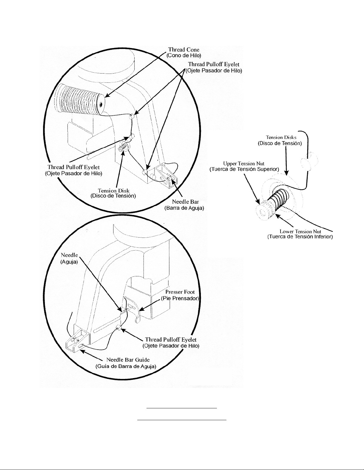
Fig 1
THREADING DIAGRAM
DIAGRAMA DE ENHEBRADO
5
Page 6
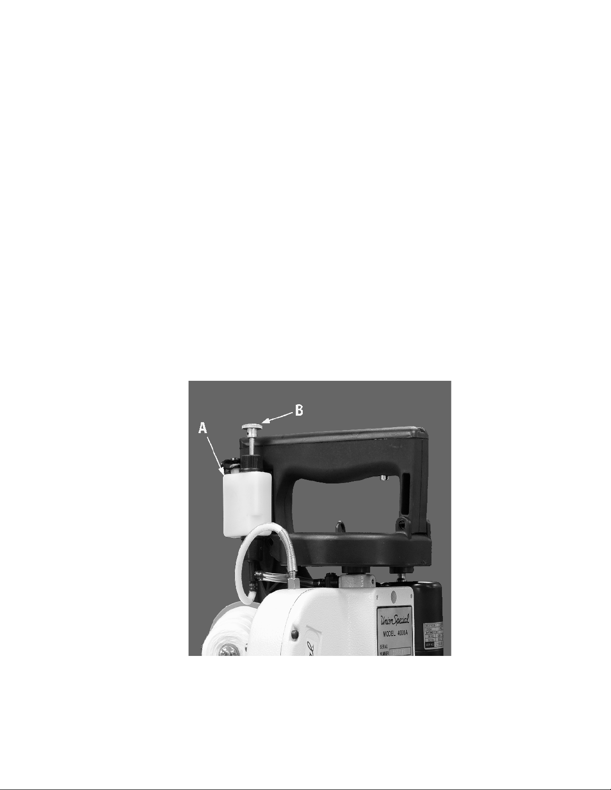
Lubrication:
Use straight mineral oil with Saybolt viscosity of 90 to 105 seconds at 100 degrees F. This is equivalent to
UNION SPECIAL Specification No. 175.
The oil has been drained from the oil pump reservoir, A (fig. 2) before shipping and the reservoir must be
filled before starting to operate. Push the pump button, B, 2 times to lubricate the moving parts before
operating the machine. This will oil the machine for approximately 4 hours of operation.
Never operate the machine with the oil reservoir cap removed.
Lubricacion:
Utilice aceite mineral con una viscosidad "SAYBOLT" de 90 a 125 segundos a 100 grados F. Esto es el
equivalente a la especificación No. 175 de UNION SPECIAL.
El aceite fue drenado del tanque A (fig 2) de la bomba de aceite antes del embarque y el tanque tiene que
ser llenado antes de operar la maquina. Oprime el botón de la bomba dos veces para lubricar las partes
móvilrs del mecanismo de la maquina. Esta cantidad de aceite lubrica la maquina para aproximadamente
4 horas.
Nunca opere la maquina sin la tapa del tanque de aceite correctamente cerrada.
Fig. 2
6
Page 7
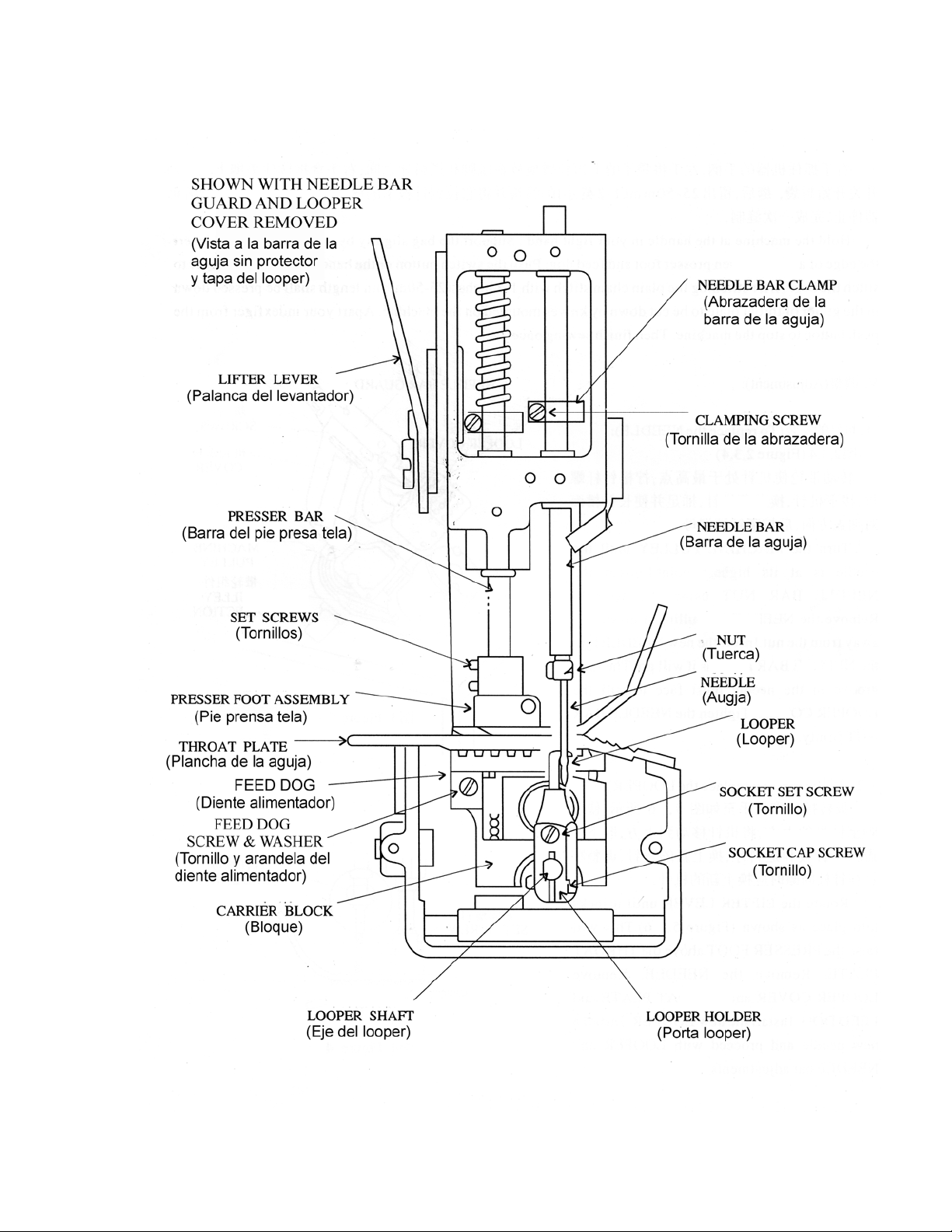
MACHINE COMPONENTS
COMPONENTE DE LA MAQUINA
Fig 3
7
Page 8
ADJUSTMENTS/AJUSTES
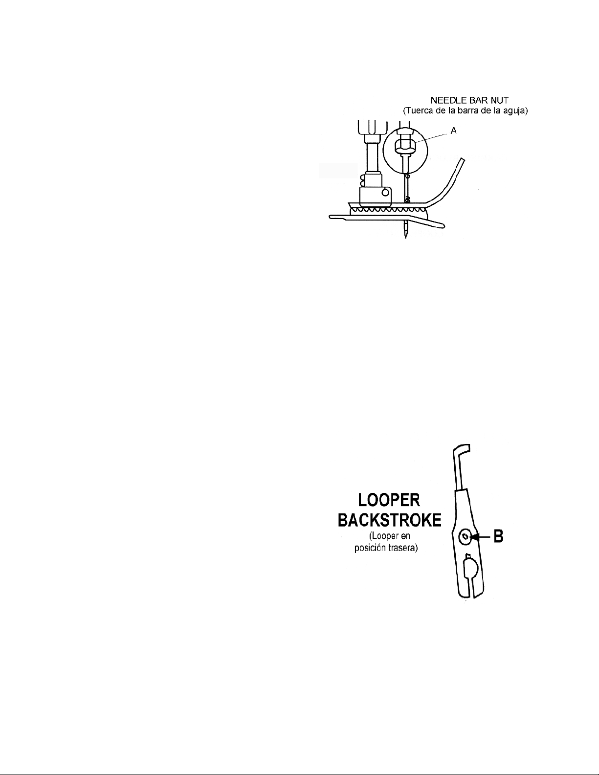
CHANGING THE NEEDLE
Loosen needle bar nut A (Fig. 4) and remove old
needle. Locate new D5 (size 200/080) needle and
insert needle into needle bar as far as it will go.
Turn needle so the the scarf of the needle is facing
right and the long groove is facing to the left.
Tighten nut A securely.
CAMBIO DE LA AGUJA
Suelte la tuerca A (Fig. 4) y remueva la aguja vieja.
Ubique la nueva aguja D5 (tamaño 200/080) e inserte la
aguja en la barra de aguja lo mas arriba que sea
posible. Gire la aguja hasta que el sacado de la
aguja este a la derecha y la ranura larga de la aguj
a a la izquierda. Apriete la tuerca A orta vez firmemente.
Fig 4
REPLACING THE LOOPER
To replace the looper, remove the looper cover,
needle, presser foot, throat plate and feed dog.
Turn the pulley until the looper is at its full back-
stroke. Loosen screw B (Fig. 5) and pull looper up
to remove. Insert a new looper as far down as it
will go and tighten screw B on the flat and then
recheck the settings.
CAMBIO DEL LOOPER
Para reemplazar el looper, remueva la tapa del
looper, la aguja, el pie prensa tela, la plancha
de la aguja y el diente transportador. Gira la
polea hasta que looper se encuentre en su
posición máxima trasera. Suelte el tornillo B (Fig. 5)
y saque el looper hacia arriba para removerlo.
Inserte el looper nuevo lo mas hacia abajo
que sea posible, apriete el tornillo B en la
parte plana del looper y revise el ajuste otra vez.
Fig 5
8
Page 9
ADJUSTMENTS CONTINUED/CONTINUACION DE LOS AJUSTES
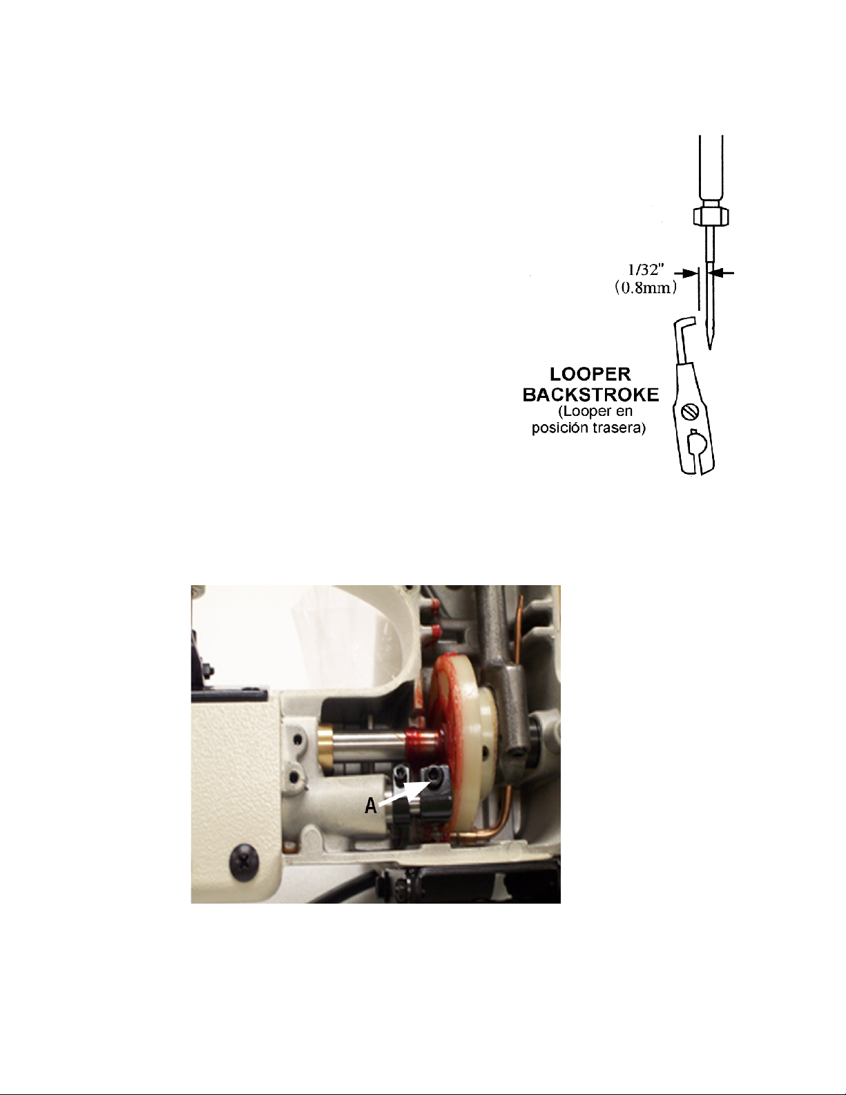
LOOPER GAUGE SETTING
Insert a new needle, type and size specified.
Looper gauge is 1/32 inch (0.8mm) which is the
distance from point of looper ( Fig. 6) to left
edge of needle when looper is at extreme
backstroke. To adjust, remove the looper
cover and housing cover and loosen allen
screw A (Fig. 7) and move looper as required
to obtain the 1/32" (0.8mm) setting, then
ighten screw A securely.
AJUST DE LA DISTANCIA DEL LOOPER
Inserte una aguja nueva del tipo y tamaño
especificado. El calibre del looper es de 1/32"
(0.8mm), que es la distancia desde la punta del
looper(Fig. 6) hasta el borde izquierdo de la agjua
en el momento cuando el looper se encuentra en
su posición máxima trasera de su recorrido. Para el
ajuste remueva la tapa del looper y la tapa de la
carcasa, suelte el tornillo Allen A (Fig. 7) y mueva
el looper como requerido para obtener la distancia
de 1/32" (0.8mm). Apriete el tornillo A otra vez
firmenmente.
Fig. 6
Fig. 7
,
9
Page 10

ADJUSTMENTS CONTINUED/CONTINUACION DE LOS AJUSTES
NEEDLE HEIGHT
Needle height is correct when the tip of the looper
is 1/64 (0.4mm) past the front edge of the needle
and the bottom of the looper is even with the top
of the needle eye (Fig 8). To adjust, remove the
looper cover and needle bar guard, then loosen
the needle bar clamping screw (Fig 3) and move
needle bar up or down so the top of the needle
eye is even with the bottom looper, then
tighten the needle bar clamping screw securely.
AJUSTE DE LA ALTURA DE LA AGUJA
La altura de la aguja esta correcta si la punta del
looper pasa 1/64" (0,4mm) por el borde derecho
de la aguja y el borde inferior de looper esata al
ras con la parte superior de ojo de la aguja.
( Fig 8). Para ajustar remueva la tapa del
looper el protector de la barra de la agjua.
Después suelte el tornillo de la abrazadera de
la barra de la guja (Fig. 3) y mueva la barra de la
agjua hacia arriba o hacia abajo hasta que la parte Fig. 8
superior del ojo firmemente el tornillo de la
abrazadera de la barra de la aguja.
OOPER CLOSENESS
L
The looper point should be set as close as possible to the
needle scarf without deflecting the needle as the looper,
moving from back to front, passes the right side of the needle.
To adjust, remove the looper cover and loosen screw
A (Fig. 9) and move the looper as required to obtain this
setting.
AJUSTE DEL LOOPER
La punta del looper debería acercarse lo máximo posible
al sacado de la aguja, pero sin tocarla, en el momento
cuando el looper en su recorrido desde atrás hacia
delante pasa por el lado derecho de la aguja. Para
hacer este ajuste, remueva la tapa del looper, suelte
el tornillo A (Fig. 9) y mueva el looper como requerido.
Fig 9
10
Page 11

ADJUSTMENTS CONTINUED/CONTINUACION DE LOS AJUSTE
FEED DOG HEIGHT
The feed dog should be set 3/32" (2.4mm)
above the top of the throat plate at its
highest point. To adjust, loosen the feed
dog screw (Fig. 3 page 7) and move the
feed dog up or down as required.
ALTURA DEL DIENTE TRANSPORTADOR
El diente transportador debería ser ajustado
en su punto más alto a una altura de 3/32"
(2,4mm) encima de la superficie de la plancha
de la aguja. Para este ajuste suelte el tornillo
del transportador (Fig.3 página 7) y mueva el
transportador hacia arriba o abajo como sea
necesario.
Fig. 10
THREAD KNIFE
The thread knife is designed so that no adjustments have
to be made. Keep the blades clean of debris and coated
with lubricant for them to work correctly. If they become
dull and need to be replaced, take the following steps:
1) Unplug the machine.
2) Remove the 2 screws A (Fig.11) holding the moving
blade to the knife bracket and remove the blade.
3) Remove the 2 screws B holding the stationary blade
to the machine housing and remove the blade.
4) Apply a thin layer of lubricant to the blades.
5) Assemble the stationary and then the moving blades
to the housing and knife bracket respectively.
6) Make certain that the screws A and B are tight.
CUCHILLA PARA HILO
La cuchilla para hilo está diseñada de manera que no
necesita ajuste alguno. Mantenga las cuchillas libres de
desperdicios y lubricadas para que éstas trabajen correcto.
Si éstas pierden el filo y necesitan ser cambiadas siga los
siguientes pasos:
1) Desconecte la máquina.
2) Retire los dos tornillos A (Fig. 11) que únen la cuchilla
móvil al el soporte y retire la cuchilla.
3) Retire los dos tornillos B que sujetan la cuchilla estacionaria
a la carcasa de la máquina y retire la cuchilla.
4) Aplique la capa delgada de lubricante a las cuchillas. Fig. 11
5) Coloque las cuchillas móvil y estacionaria a la carcasa y
soporte de la cuchilla, respectivamente.
6) Asegúrese de que los tornillos A y B estén bien apretados.
11
Page 12

ADJUSTMENTS CONTINUED/CONTINUACION DE LOS AJUSTE
BELT TENSION
The belt must remain slightly flexible with
1/8" to 3/16" (3-4mm) movement (Fig. 12).
Apply tension to the belt by opening the
motor mount hinge and tightening the
2 screw A (Fig. 13).
TENSION DE LA CORREA
La correa deberá quedar ligeramente
flexible contra 1/8" para 3/16" (3-4mm) Fig. 12
movimiento (Fig.12).
Aplique tensión a la correa abriendo el
conjunto abisagrado del motor y
apretando los dos tornillos A (Fig. 13).
Fig 13
12
Page 13

TROUBLESHOOTING/PROBLEMAS DE FUNCIONAMIENTO
1) Stitch is too loose. 1) Puntada muy suelta.
A) Check the thread tension. A) Revise la tensión de hilo.
B) Check the sharpness of the feed B) Revise el filo de los dientes del
dog and throat plate teeth. alimentador dentado y de la
placa de garganta.
2) Stitch is too short. 2) Puntada muy corta.
A) Check the sharpness of the feed
dog and the throat plate teeth. A) Revise el filo de los dientes del
alimentador dentado y de la
3) The bag is tearing at the sewing line. placa de garganta.
A) Be sure your not holding back the
machine from traveling across the 3) La bolsa se esta rasgando en la
bag top. The machine must be linea de costura.
moved across the bag at the same
same rate the the feed dog feeds A) Agegúrese de no esta manteriendo
the bag through the machine. la máquina hacia atrás de manera que
B) If the bag is moving on a conveyor, interrumpa el recorrido a través del
be sure the machine is being moved tope de la bolsa. La máquina deberá
across the bag at the same rate that moverse a lo largo de la bolsa a la
the feed moves the bag through the misma velocidad en que el alimentador
machine. dentado mueve la bolsa a través de
C) Check the pressure on the presser foot. la máquina.
D) Has the bag quality changed and has B) Si la bolsa se está moviendo en una
the machine been adjusted to banda transportadora, asegúrese de
accommodate the new bag? que la máquina se este moviendo a
lo largo de la bolsa a la misma
4) The machine is no longer running. velocidad que el alimentador dentado
dentado mueve la bolsa a través de
A) Is the machine securely connected la máquina.
to the power supply? C) Revise la presión en el pie prensador.
B) Check the power cord to see if there D) Ha cambiado la calidad de la bolsa
are any breaks. y ha sido ajustada la máquina para
C) If the switch on the handle does not acomodarse la nueva bolsa?
click when pressed, replace the
switch. 4) La máquina no funciona
D) Check the motor brushes and
replace them if they are too short. A) Está bien conectada la máquina al
abastecedor de energia?
5) The thread keeps breaking B) Revise el cable eléctico para ver si
tiene alguna rotura.
A) Is the thread unrolling easily from C) Si el interruptor en el mango no suena
the cone? cuando se presiona, reemplace el
B) Check the thread tension. interruptor.
C) Check the thread guides and make D) Revise las escobillas del motor y
sure they are clean. reemplácelas si están muy cortas.
D) The needle is getting too hot.
5) El hilo se rompe continuamente.
13
A) Se desenrolla fácilmente el hilo del cono?
B) Revise la tensión del hilo.
C) Revise las guias del hilo y asegúrese de que
estén limpas.
D) La aguja se está calentando mucho.
Page 14

TROUBLESHOOTING/PROBLEMAS DE FUNCIONAMINETO
6) The machine is skipping stitches or does 6) La máquina está saltando puntasdas o no
not make a thread chain at the end of the hace una cadena de hilo al final de la
bag. bolsa.
A) Check thread tension A) Revise la tensión del hilo.
B) Make sure the thread guides are B) Asegúrese de que las guias del hilo
clean and that thread can easily estén limpas y que el hilo pueda
pass through them. pasar fácilmente a través de ellas.
C) Is the thread unrolling from the C) Se desenrolla fácilmente el hilo del
cone easily? cono?
D) Check the teeth on the feed dog D) Revise el filo de los dientes del
and throat plate. Replace them alimentador dentado y de la placa
if they are dull. de garganta. Reemplácelas si
están sin filo.
E) Check if the needle is loose or E) Revise si la aguja está suelta o
misaligned. desalineada.
F) Check if the looper is loose, F) Revise se el Ojo-Guia está flojo,
worn or needs to be re set. gastado o necesita ser ajustado.
G) Make sure the machine is G) Asegúrese de que la máquina esté
properly threaded. enhebrada correctamente.
7) The needles keep breaking 7) Las agujas se rompen continuamente
A) Check the looper and needle A) Revise la alineación el ojo-guia
alignment. y la aguja.
B) Check the needle alignment to B) Revise la alineación de la aguja
the throat plate and presser con la placa garganta y guia
needle guide. de aguja del pie prensador.
14
Page 15

SPARE PARTS/PARTES DE REPUESTO
15
Page 16

16
Page 17

HOUSING, NEEDLE LEVER, PRESSER FOOT & THROAT PLATE PARTS
Ref.
No.
1.
1-1.
1-2.
1-3.
1-4.
1-5.
1-6.
2.
3.
4.
5.
5-1.
6.
6-1.
7.
8.
9.
10.
11.
11-1.
12.
12-1.
13.
14.
15.
16.
17.
18.
19.
20.
20-2.
20-3.
20-4.
21.
22.
22-1.
23.
24.
25.
25-1.
26.
27.
28.
29.
30.
31.
31-1.
32.
33.
34.
34-1.
35.
36.
37.
Part No.
-4001201-1
4001201-2
4001201-3
4001201-4
4001201-5
4001201-6
-4001203
-4001205
4001205-1
4001206
4001206-1
4001207
4001208
4001209
4001210
4001211
4001211-1
4001212
4001212-1
4001213
4001214
4001215
4001216
4001217
4001218
4001219
4001220A
4001220A-2
4001220A-3
4001220A-4
4001221
4001222
4001237
4001223
4001224
4001225
4001225-1
-4001227
4001228
4001229
4001230
4001231
4001466-1
4001232
4001233
4001234
4001234-1
4001235
4001236
4001237
Description
Housing Assembly (Not available)..................................................................
Set Screw, #8-32N.C. X 3/16"................................................................................
Spring ....................................................................................................................
Joint................................................................ ...................................................
Oil pipe..................................................................................................................
Nut............ ........................................................................................................
Washer..............................................................................................................
Cover(Not available)....................................................................................
Screw, #8-32N.C. X 5/8"......................................................................................
Plate (Not available)......................................................................................
Stud, Feed Dog carrie slide...............................................................................
Screw, button head #10-32N.F X 1/4"...............................................................
Cover, Looper..................................................................................................
Stud, Looper cover..........................................................................................
Screw, flathead, #6-40N.E X 3/8".................................................................
Throat Plate........................................ ...............................................................
Screw, #6-32N.C. X 3/16....... .........................................................................
Tube, Thread Guide (Front).............................................................................
Guard, Needle Bar..........................................................................................
Screw, #8-32N.C. X 1/4"..................................................................................
Cover plate.....................................................................................................
Screw, #10-32N.E. X 1/4...................................................................................
SlidePad Cover..............................................................................................
Slide Pad...........................................................................................................
Lever Plate............................................................................................................
Screw, #8-32N.C. X 5/16"...............................................................................
Lifter Lever, Presser Foot...............................................................................
Washer, Spring.................................................................................................
Screw, Pivot......................................................................................................
Presser Foot Assembly....................................................................................
Hinging Bolt.......................................................................................................
Nut ......................................................................................................................
Screw, #8-32N.C. X 3/16"................................................................................
Bushing, (lower).................................................................................................
Lifter, Presser Foot.............................................................................................
Screw, #6-40N.F. X 1/2" ..................................................................................
Spring, Presser Bar...........................................................................................
Presser Bar........................................................................................................
Bushing, Needle Bar (upper)..........................................................................
Bushing, Presser Bar (upper)...........................................................................
Needle..............................................................................................................
Nut, Needle Bar...............................................................................................
Bushing, Needle Bar (lower)...........................................................................
Needle Bar......................................................................................................
Oil Felt...............................................................................................................
Clamp Assembly, Needle Bar.........................................................................
Screw................................................................................................................
Lock Nut (Nylok Special) 3/8" X 24 N.C..............................................................
Washer, Flat......................................................................................................
Pivot Pin...........................................................................................................
Bushing..............................................................................................................
Washer, Thrust for Needle Lever....................................................................
Pivot Clamp, Needle............................................................................................
Screw, #6-40N.F. X 5/8".......................................................................................
Amt.
Req.
1
8
1
1
1
1
1
1
6
1
1
4
1
1
3
1
4
1
1
3
1
1
1
1
2
1
1
1
1
1
1
1
1
1
1
1
2
1
1
1
1
1
1
1
1
1
2
1
1
1
1
5
1
1
38. thru 51. See following page.
17
Page 18

18
Page 19

HOUSING, NEEDLE LEVER, PRESSER FOOT & THROAT PLATE PARTS (CONT'D)
Ref.
No.
38.
38A.
39..
40..
41..
42..
43..
44..
45..
46..
47..
48..
49..
50..
51..
Part No.
4001238
4001238A
4001239
4001240
4001241
4001242
4001207
4001244
4001245
4001246
4001247
4001248
4001249
4001250
4001251
Description
Needle Bar Lever Clamp Assenmbly............................................................
Needle BarLever Clamp Assembly with Clamp..........................................
Spring.................................................................................................................
Flat Washer.......................................................................................................
Screw, #10-32N.F. X 1/2"........................................ ........................................
Tension Assembly Complete.........................................................................
Screw, #6-40N.F. X 3/8"...............................................................................
Tension Nut (upper)......................................................................................
Lock Washer for Tension................................................................................
Tension Nut (lower).........................................................................................
Tension Spring..................................................................................................
Tension Disc ..................................................................................................
Tension Stud ................................................................................................
Eyelet, Thread Pull Off.................................................................................
Tube, Thread Guide (rear)...........................................................................
Amt.
Req.
1
1
1
1
1
1
1
1
1
1
1
2
1
2
1
19
Page 20

20
Page 21

MAIN SHAFT & LOOPER ASSEMBLY PARTS
Ref.
No.
52..
52-1-
52-2..
53..
53-1..
54..
55..
56..
57A..
57..
57-1..
57-2..
57-3..
59..
60..
61..
58..
58-1..
58-2..
62..
63..
64..
64-1..
64-2..
65..
66..
66-1..
67..
68..
69..
69-1..
69-2..
70..
71..
72..
73..
74..
75A.
75..
75-1.
76..
77..
77-1..
78..
79..
80..
81..
82..
83..
84..
84-1.
85..
85-1.
86..
87..
88..
Part No.
4001452
4001452-1
4001452-2
4001453
4001453-1
4001454
4001455
4001456
4001457A
4001457
4001480
4001457-2
4001457-3
4001459
4001460
4001461
4001458
4001458-1
4001458-2
4001462
4001463
4001464
4001464-1
4001464-2
4001465
4001466
4001466-1
4001467
4001468
4001469
4001469-1
4001469-2
4001470
4001471
4001472
4001473
4001474
4001475A
4001475
4001475-1
4001476
4001477
4001477-1
4001478
4001479
4001480
4001481
4001482
4001483
4001484
4001484-1
4001485
4001485-1
4001486
4001487
4001488
Description
Mainshaft..............................................................................................................
Screw.............................................................................................................
Oil Felt............................................................................................................
Collar, Mainshaft............................................................................................
Screw, #5-40N.C. X 3/8"................................................................................
"O" Ring............................................................................................................
Washer, thrust.................................................................................................
Bushing, Mainshaft (rear)................................................................................
Connecting Rod & Eccentric Assembly with Bearing Rod Ends................
Connecting Rod & Eccentric Assembly...............
Screw...... .....................................................................................................
Screw, (cone point)........................................................................................
Screw (flat point) ............................................................................................
Washer, Internal tooth, 5/16"............................................................................
Nut, Hex Head.................................................................................................
Bearing, Rod End...........................................................................................
Cam Looper Assembly...................................................................................
Screw, #10-32N.F. X 5/8"(cone point).......................................................
Screw, #10-32N.F. X 1/2"..............................................................................
Arm & Stud Cam Follower Assembly............................................................
Cam Follower Stud...........................................................................................
Cam Follower Arm....... ...............................................................................
Screw, #5-40N.C. X 5/8"........ .....................................................................
Washer, Flat ..............................................................................................
Nut, Hex Head..............................................................................................
Collar, Looper Shaft.........................................................................................
Screw, #5-40N.C. X 1/2"..............................................................................
Shaft, Looper..................................................................................................
Bushing, Looper Shaft......................................................................................
Looper Holder.......... ......................................................................................
Screw, #8-32N.C. X 3/16"...........................................................................
Screw, #5-40N.C. X 1/4"............................................................................
Looper..............................................................................................................
Bushing, Mainshaft (front) .............................................................................
Screw, #8-32N.C. X 5/16".....................................................................................
Washer, internal tooth #8.............................................................................
Angle Clip........................................................................................................
Carrier Block Assembly with Slide...............................................................
Carrier Block, Feed Dog...........................................................................
Screw, #6-40N.F. X 3/8"..............................................................................
Washer, Felt.....................................................................................................
Slide...................................................................................................................................................
Knife Slide...........................................................................................................
Feed Dog.........................................................................................................
Washer, Flat #8 ................................................................................................
Screw, #8-32N.C. X 1.......................................................................................
Screw, #10-32N.F. X 3/8".................................................................................
Washer, Lock #10................................................................................................
Bracket, Knife...................................................................................................
Knife, Stantionary.......................................................................................
Screw, #3-48N.C. X 5/16".........................................................................
Knife, Moving...........................................................................................
Screw, #3-48N.C. X 3/16..........................................................................
Bushing, Knife Shaft..................................................................................
Shaft, Knife................................................................................................
Spring, Knife Tension.................................................................................
Amt.
Req.
1
1
1
1
1
1
3
1
1
1
1
1
1
1
1
1
1
1
1
1
1
1
1
1
2
2
2
1
1
1
1
2
1
1
1
1
1
1
1
1
1
1
1
1
1
1
1
1
1
1
1
1
1
1
1
1
21
Page 22

22
Page 23

HANDLE & ELECTRIC DRIVE PARTS
Ref.
No.
1.
3.
4.
5.
5-1.
6.
7.
8.
9.
10.
11.
12.
13.
14.
15.
19.
20.
21.
22.
23.
24.
24-1.
25.
26.
26-1.
26-2.
27.
28.
28-1.
29.
30.
30-3.
31.
32.
33.
34.
34-1.
35.
36.
37.
38.
38-1.
39
39-1.
40.
41.
42.
43.
44.
45.
46.
47.
48.
49.
Part No.
4001601
4001603
4001604
4001605
4001605-1
4001606
4001607
4001608
4001609
4001610
4001611
4001612
4001216
4001614
4001615
4001619
4001620
4001621
4001473
4001623
4001624
4001624-1
4001625
4001626
4001626-1
4001626-2
4001627
4001628
4001628-1
4001629
4001630
4001630-3
4001631
4001632
4001633
4001634
USST0.5
4001635
4001636
4001637
4001638
4001638-1
4001639
-
4001639-1
4001639M
-
4001639-1M
4001640
4001641
4001642
4001643
4001644
4001645
4001646
4001647
90191M
90191MA
Description
Oil Pump Assembly....... ................................................................................
Screw, #8-32N.C. X 1/2" .....................................................................................
Spring, Garter ......................................................................................................
Tubing, Oil Pump (4X6X10.5)...........................................................................
Tubing, Oil Pump (4X6X20.5)................................................................................
"O" Ring.............................................................................................................
Screw, #8-32N.C. X 1/4"...................................................................................
Manifold, Outside .............................................................................................
"O" Ring..............................................................................................................
Tubing, (4X6X11.5)...........................................................................................
Weldment, Manifold (inside)...........................................................................
Fitting, Barbed..................................................................................................
Screw, #8-32N.C. X 5/16"...............................................................................
Pin, Spring (1/4" Dia X 1/2").................................................................................
Guard, Belt.... ..................................................................................................
Belt..... ..............................................................................................................
Hanger ............................................................................................................
Clip, Hanger....................................................................................................
Washer, Internal Tooth #8...................................................................................
Nut, Hex #8-32N.C............................................................................................
Pulley .............................................................................................................
Screw, #10-32N.F. X 3/8"......................................................................................
Screw, #10-32N.F. X 3/8"" ..........................................................................
Cover, Handle................................................................................................
Micro Switch...................................................................................................
Flexible Terminal block..................................................................................
Screw, #4-4-NH.C. X 3/8"...............................................................................
Switch...............................................................................................................
End Plug............................................................................................................
Wire Nut............................................................................................................
Cord, Set for 110V...........................................................................................
Cord, Set for 220V...........................................................................................
Screw, 1/4-20N.C. X 3/4"................................................................................
Washer, Spring 1/4"..........................................................................................
Handle...............................................................................................................
Bolt, Thread Clamping....................................................................................
Thread...............................................................................................................
Screw, #10-32N.F. X 3/8".................................................................................
Stain Relief........................................................................................................
Motorlead-3 Wire SJO....................................................................................
Motor Pulley.....................................................................................................
Screw............................................................................................................
Universal Motor Assembly (110V).................................................................
Universal Motor Assembly (220V).................................................................
Universal Motor (110V)...................................................................................
Universal Motor (220V)...................................................................................
Thread Stand Base..........................................................................................
Wing Nut, 1/4-20N.C.......................................................................................
Hinge Motor Mount Assembly........................................................................
Screw................................................................................................................
Washer for Motor............................................................................................
Carbon Brush for AC Motor (size:6X8X15)...................................................
Cap for Motor.................................................................................................
Screw with Washer..........................................................................................
Spring Balancer (Extra Send and Charge Item).........................................
Hanging Hook for Spring Balancer (Extra Send and Charge Item)..........
Amt.
Req.
1
1
4
1
1
1
1
1
1
1
1
1
1
2
1
1
1
1
1
1
1
2
1
1
1
1
1
1
1
2
1
1
2
1
1
1
1
1
1
1
1
1
1
1
1
1
1
1
4
2
1
1
1
1
1
1
.
23
Page 24

24
Page 25

MOTOR PARTS PARTS
Ref.
No.
1.
2.
3.
4.
5.
7.
8.
11.
12.
13.
14.
15.
17.
18.
19.
20.
Part No.
4002601
4002602
4002603
4002604
4002604-1
4002605
4002607
4002607-1
4002608
4002611
4002612
4002613
4002614
4002615
4001645
4002618
4001646
4001647
Description
Cord ............................................................................................................
Strain Relief Busings...........................................................................................
Case A............................................. ...................................................................
Stator Assembly for 110V................................................................................
Stator Assembly for 220V................................................................................
Ball Bearing.......................................................................................................
Armature Assembly for 110V.........................................................................
Armature Assembly for 220V..........................................................................
C-Ring.............................................................................................................
Screw...............................................................................................................
Pipe........................................... ........................................................................
PC Plate...........................................................................................................
Washer...................... .......................................................................................
Nut .....................................................................................................................
Carbon Brush for AC Motor...........................................................................
Case B.............................................................................................................
Cap for Motor..................................................................................................
Screw ...............................................................................................................
Amt.
Req.
1
1
1
1
1
1
1
1
1
1
1
1
1
1
1
1
1
1
25
Page 26

26
Page 27

ACCESSORIES
Ref.
No.
1.
2.
3.
4.
5.
6.
6-1.
7.
7-1.
8.
9.
Part No.
28604R
4002403
22933105
4002405
WR64
WR70
WR75
WR68
4001645
D5
Description
Accessory Bag ............................................................................................
Oil .....................................................................................................................
Spanner Wrench............................. ..............................................................
Screwdriver......................................................................................................
2.0mm Allen Wrench......................................................................................
3/32" Allen Wrench.........................................................................................
7/64" Allen Wrench........................................................................................
5.0mm Allen Wrench.....................................................................................
9/64" Allen Wrench.........................................................................................
Carbon Brush for AC Motor (size:6X8X15)...................................................
Needles Size 200/080......................................................................................
Amt.
Req.
1
1
1
1
1
1
1
1
1
2
2
27
Page 28

 Loading...