

Union Special 395 Series User Manual
CATALOG
NO.
Adjusting
instructions
and
395M
First
Edition
STYLES
395-20
395-21
395-22
395-23
395-26
395-26V
395-28
illustrated
parts
list
395-28V
395-40
395-40V
395-42
395-42V
Finest
•••
Quality
6M
Classic
-Differential
Series
feed
overseamers
Equipment
ADJUSTING
INSTRUCTIONS
AND
ILLUSTRATED
6M
CLASSIC
FEED
OVER
Catalog
395-20
395—21
395-22
395-23
395-26
395—26V
PARTS
SERIES
SEAMING
No.
For
Styles
LIST
ON
-
DIFFERENTIAL
MACHINES
395
M
395-28
395—28V
395-40
395-40V
395-42
395-42V
Rights
Union
Reserved
First
Copyright
Special
Printed
September,
Edition
1981
By
Corporation
In
All
In
U.S.A.
1981
2
Countries
EQ
REWO
RD
This
new
UNION
adjusting
liability
The
setting
functions
Check
and
rectly.
adjustments
ence
letters
Adjustments
plished.
the
function
Implementation
cant
improvements
Whenever
sure
to
fically
ing
service.
technical
SPECIAL
these
designed
Adjusting
for
each
of
Procedure.
The
are
Some
it
becomes
insist
for
your
machine.
machines
of
the
machine.
Procedure
required.
to
point
are
adjustments
of
other
in
genuine
on
machine
manual
will
and
built
Instructions
components
the
The
Check
is
given
Figures
out
specific
presented
performed
related
preventative
of
operator
necessary
UNION
and
has
been
Careful
enable
into
every
portion
The
text
depicts
to
explain
are
items
in
sequence
parts.
productivity
make
to
SPECIAL
manufactured
prepared
attention
you
to
UNION
of
related
of
the
conditions
used
discussed.
of
out
maintenance
by
repairs
Repair
with
guide
to
to
the
maintain
SPECIAL
this
manual
forming
to
Adjustments
when
proper
the
illustrate
to
so
that
a
sequence
procedures
avoiding
replace
or
Parts.
utmost
in
you
instructions
the
superior
machine.
explains
the
stitch
is
divided
the
steps
the
logical
may
have
can
costly
parts
These
parts
precision
the
maintenance
for
performance
in
and
into
parts
to
be
are
taken
adjustments
progression
an
adverse
bring
equipment
on
your
are
to
assure
operating
detail
completing
two
adjusted
in
about
breakdowns.
machine,
designed
the
sections
the
using
is
accom
effect
signifi
long
of
and
proper
cor—
event
refer
on
be
speci
last
your
and
re
the
-
To
exploded
VIEW
which
illustrated
simplify
views.
presents
on
identification
These
the
this
page
illustrations
mechanisms
will
of
appear
repair
will
of
the
shaded
parts,
usually
machine
in
the
be
assembled.
the
KEY
mechanisms
shown
3
in
VIEW.
are
illustrated
conjunction
The
specific
with
parts
a
by
KEY

CLASS
DESCRIPTION
I-ugh
Speed,
overseaming
cam
driven
395-20
-
hemmer
cular
inch
one
and
machines.
main
and
STITCH
SEAM
FEED
MAXIMUM
AND
TYPE
SYSTEM
SPEED
(Depending
operati
on)
LUBRICATION
One
needle,
assembly
blind
hemming/welting
(3.2mm).
two
curved
Fabric
differential
on
thread
two
with
overhanging
needles,
trimmer
feeds.
TECHNICAL
EFc-l,
503
SSa-l,
504
40V,
512
SSa—l,
Independent,
Differential
6000
Enclosed
Reservoir.
MACHINE
machine
operations
two,
with
42,
RPM,
produces
hem
three
spring
Enclosed
DATA
Styles
Styles
42V.
Styles
Cam
Feeds.
All
Styles.
Automatic
STYLES
guides.
on
“I”
and
pressed
automatic
395-20,
395-26,
395-22,
Driven
Splash
break
Typical
shirts.
four
lower
21.
26V,
23.
Main
System,
open
thread,
knife.
lubrication
28,
and
Single
seam.
Fitted
Application
Available
differential
Independent
system.
40,
28V,
with
-
Flat
seam
compact
or
width:
feed
cir
1/8
395-21
395-22
duces
dresses
395-23
395-26
cal
3/32
395-26V
395-28
395-28V
395-40
Application
3/32
395-40V
395-42
-
Same
-
Two
simulated
-
Same
-
One
Application
inch
-
Same
-
Same
-
Same
-
One
inch
-
Same
-
Same
as
Style
needle,
and
draperies.
as
Style
needle,
(2.4mm),
as
as
Style
as
needle,
-
(2.4mm),
as
as
Style
Style
Style
For
Style
395-20
four
‘Safety
395-22
three
-
For
1/8
395-26
395-26
395-28
three
curved
1/8
395-40
395-40
thread
Stitch”.
Available
thread
curved
inch
thread
inch
except
machine
except
(3.2mm),
except
except
except
seams
(3.2mm),
except
except
extra
Typical
seam
extra
machine
seams
fitted
extra
fitted
machine
on
knit
fitted
extra
stitch
prepared
width:
stitch
prepared
knit
on
5/32
with
stitch
with
prepared
undergarments.
5/32
with
stitch
cams
with
and
high
Application
17/64
cams
and
high
with
undergarments.
inch
(3.9mm).
“AIR-KLIPP’
and
cams
“AIR-KLIPP”
with
inch
low
(3.9mm).
“AIR-KLIPP”
and
cams
needles
throw
-
inch
needles
needles
throw
Available
needles
crankshaft.
Seaming
(6.7mm)
throw
Available
chain
chain
crankshaft.
chain
are
furnished.
bathing
furnished.
are
crankshaft.
seam
cutter.
are
furnished.
cutter.
seam
cutter.
are
furnished.
Pro
suits,
Typi
widths:
Typical
widths:
395-42V
-
Same
as
Style
395-42
except
fitted
with
“AIR-KLIPP”
4
chain
cutter.
Each
UNION
stamped
The
serial
machine
in
-
SPECIAL
the
style
number
machine
plate
stamped
is
IDENTIFICATION
carries
located
in
the
a
style
the
to
extension
OF
number,
right
of
MACHINES
which
rear
of
casting
on
the
at
this
class
machine.
the
right
machine
rear
base
is
of
TO
PREVENT
-
All
power
justing
-
Wear
-
All
shields
-
DO
NOT
Oil
mineral
equivalent
THIS
or
safety
tamper
capacity
oil
to
SAFETY
PERSONAL
sources
replacing
glasses.
and
guards
with
of
with
a
Saybolt
UNION
SYMBOL
INJURY:
to
the
parts.
MUST
safety
Class
SPECIAL
INDICATES
machine
in
be
shields,
395
is
eight
viscosity
specification
SAFETY
RULES
A
CAUTION!
YOUR
MUST
position
guards,
LUBRICATION
of
be
TURNED
ounces
90
to
No.
PERSONAL
etc.,
before
(227
125
175.
SAFETY
OFF
before
operating
while
milliliters).
seconds
IS
threading,
machine.
machine
at
100
INVOLVED.
is
in
operation.
Use
a
degrees
oiling,
straight
F.
This
ad
is
oil
bulb
Clean
Oil
and
in
operating
240
on
the
Styles
looper
Machine
level
on
oil
To
drain
magnetic
MUST
Before
cloth
are
furnished
Be
sure
following
using
Thread
thread,
at
level
be
changed
threading
plate
machine
is
filled
sight
oil
plug
out
direction
with
machine
pages.
three
two
with
gauge
indicator
remove
of
any
periodically
machine;
of
position
until
machine
is
threaded
threads
in
the
thread
oil
on
front
will
magnetic
metallic
needle
Use
Figure
and
following
styles
at
of
register
plug
to
unlock
and
aid
to
properly
Figure
DO
spring
cap
machine.
between
from
material
minimize
THREADING
presser
pull
is
upper
at
in
threading.
highest
according
1
for
Styles
lB
for
sequences:
require
NOT
5
back
that
wear.
foot
two
in
top
When
of
looper
using
needle
(1)
this
cover.
proper
red
gauge
machine
may
have
release
thread
position.
the
to
two
lower
step.
oil
lines.
near
accumulated
bushing,
threading
threads,
Styles
looper
(3)
Before
level
bottom
tube
Thread
using
thread
needle(s).
operating,
is
swing
Turn
up.
tweezers
diagrams
Figure
four
reached,
edge
in
crankcase.
presser
handwheel
lA
threads.
(2)
of
No.
shown
for
upper
check
red
base.
arm
660—
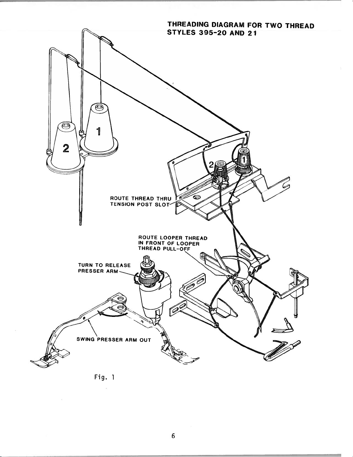
THREADING
STYLES
395-20
DIAGRAM
AND
FOR
21
TWO
THREAD
TURN
PRESSER
TO
ROUTE
TENSION
RELEASE
ARM
THREAD
ARM
POST
ROUTE
IN
FRONT
THREAD
OUT
LOOPER
OF
PULL-OFF
THREAD
LOOPER
--—-A
Fig.
1
6
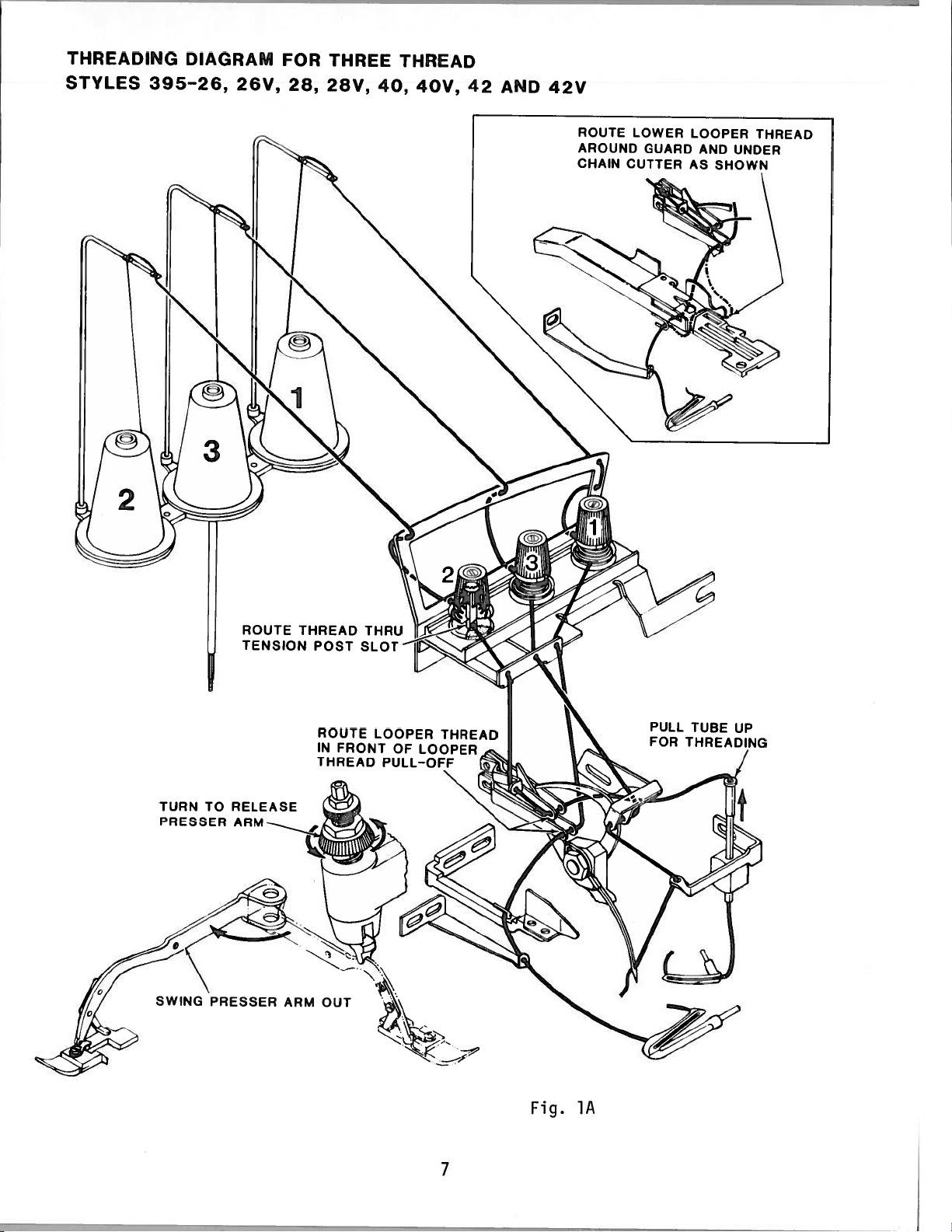
THREADING
STYLES
395-26,
DIAGRAM
26V,
FOR
28,
THREE
28V,
THREAD
40,
40V,
42
AND
42V
ROUTE
AROUND
CHAIN
LOWER
GUARD
CUTTER
LOOPER
AND
AS
SHOWN
THREAD
UNDER
TURN
PRESSER
SWING
RELEASE
TO
ARM
PRESSER
TENSION
ARM
ROUTE
IN
FRONT
THREAD
OUT
LOOPER
OF
PULL-OFF
THREAD
LOOPER
PULL
FOR
TUBE
THREADING
UP
Fig.
7
A
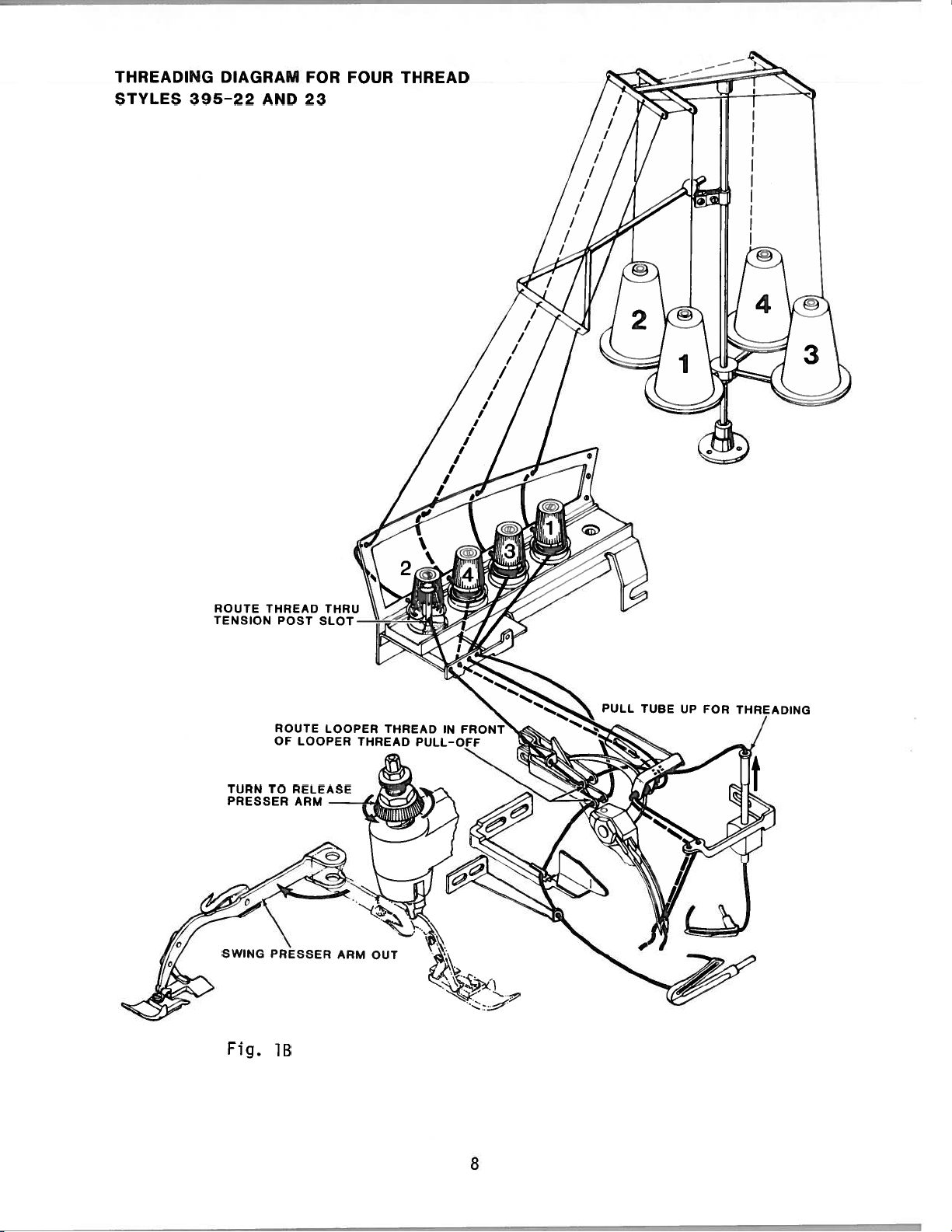
THREADING
STYLES
395-22
DIAGRAM
AND
FOR
23
FOUR
THREAD
TURN
PRESSER
SWING
Fig.
TO
RELEASE
ARM
PRESSER
18
ARM
OUT
PULL
TUBE
UP
FOR
8
—
NOTE:
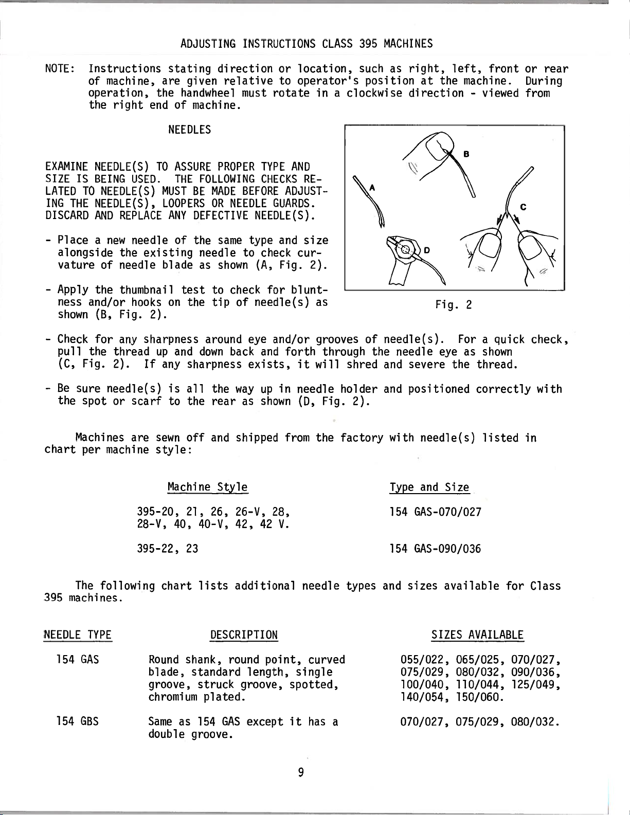
EXAMINE
SIZE IS
LATED
ING
DISCARD
-
TO
THE
Place
alongside
vature
-
Apply
ness
shown
-
Check
pull
(C,
Fig.
Instructions
of
machine,
operation,
the
right
NEEDLE(S)
BEING
NEEDLE(S),
AND
a
USED.
NEEDLE(S)
REPLACE
new
needle
the
of
needle
the
thumbnail
and/or
(B,
for
the
hooks
Fig.
any
thread
2).
ADJUSTING
stating
are
the
handwheel
end
of
NEEDLES
TO
ASSURE
THE
MUST
LOOPERS
ANY
of
existing
blade
test
on
2).
sharpness
and
up
If
any
direction
given
relative
machine.
PROPER
FOLLOWING
BE
MADE
OR
NEEDLE
DEFECTIVE
same
the
needle
as
shown
check
to
the
tip
around
down
back
sharpness
INSTRUCTIONS
or
location,
to
operator’s
must
BEFORE
of
rotate
TYPE
CHECKS
GUARDS.
NEEDLE(S).
type
and
to
check
Fig.
(A,
for
needle(s)
eye
and/or
and
exists,
AND
ADJUST
cur
blunt
forth
it
CLASS
in
a
RE
size
2).
as
grooves
through the
will
MACHINES
395
such
position
clockwise
needle(s).
of
shred
and
as
right,
direction
needle
severe the
at
left,
the
machine.
Fig.
2
Foraquick
eye as
-
viewed
shown
thread.
front
or
rear
During
from
check,
-
Be
sure
the
Machines
chart
The
395
machines.
NEEDLE
154
spot
per
TYPE
GAS
needle(s)
scarf
or
are
machine
395—20,
28-V,
395-22,
following
is
all
to
the
sewn
off
style:
Machine
21, 26,
40,
23
chart
Round
shank,
blade,
groove,
chromium
the
way
rear
shipped
and
Style
26—V.
40-V.
lists
42,
additional
DESCRIPTION
round
standard
struck
plated.
up
as
shown
42
point,
length,
groove,
in
28,
V.
needle
(D,
from
needle
curved
single
spotted,
the
Fig.
holder
2).
factory
types
and
positioned
with
Type
154
154
and
needle(s)
and
Size
GAS-O70/027
GAS-090/036
sizes
available
SIZES
055/022, 065/025,
075/029, 080/032,
100/040,
140/054,
correctly
listed
AVAILABLE
110/044,
150/060.
in
for
Class
070/027,
090/036,
125/049,
with
154
GBS
Same
double
as
groove.
154
GAS
except
it
has
a
9
070/027,
075/029,
080/032.
NEEDLE
TYPE
DESCRIPTION
SIZES
AVAILABLE
154
154
154
154
To
needle
complete
GES
GHS
GJS
GLS
have
or
type
order
needle
and
would
Same
shorter
Same
ball
Same
tapered
Same
ball
orders
size
read
as
154
blunt
as
154
point.
as
154
blade.
as
154
eye.
number
“1000
GAS
point.
GAS
GAS
GAS
promptly
should
needles,
except
except
except
except
and
accurately
be
counterclockwise
left.
until
clamp
(A,
it
has
it
has
has
it
has
it
forwarded.
Type
154
Rotate
Turn
needle(s) is
nut
Fig.
a
a
a
a
filled,
GAS,
presser
handwheel
using
3),
Use
description
Size
NEEDLE
and
socket
then
remove
055/022, 065/025,
075/029,
100/040,
140/054,
080/032, 090/036,
110/044, 125/049,
150/060
065/025, 070/027,
080/032,
055/022,
075/029,
090/036
065/025,
080/032,
100/040
070/027, 075/029,
empty
100/040
package,
on
label.
090/036,
an
075/029”.
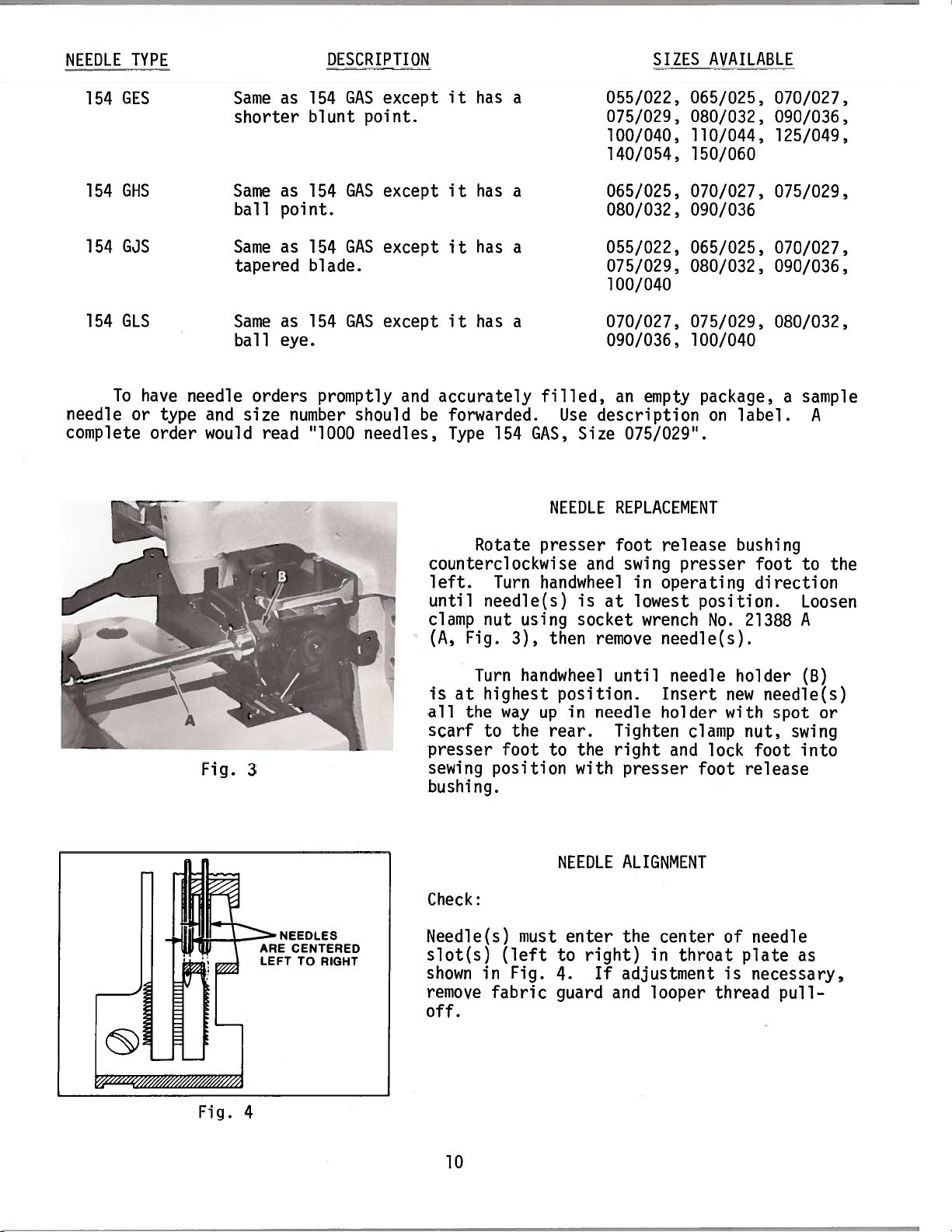
REPLACEMENT
bushing
position.
No.
at
foot
swing
in
lowest
release
presser
operating
wrench
needle(s).
070/027,
075/029,
070/027,
090/036,
080/032,
foot
direction
21388
sample
a
to
Loosen
A
A
the
Fig.
Fig.
4
3
ARE
LEFT
NEEDLES
CENTERED
TO
RIGHT
Turn
is
at
all
the
scarf
presser
sewing
bushing.
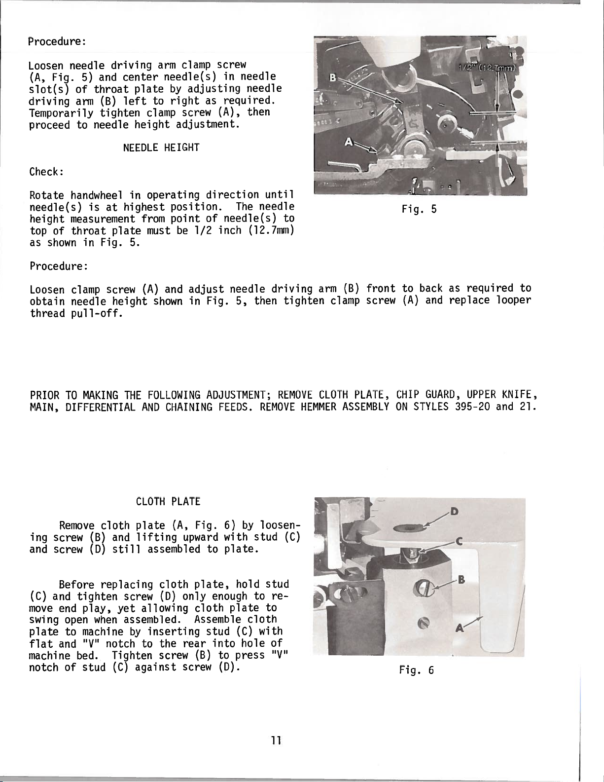
Check:
Needle(s)
slot(s)
shown
remove
off.
highest
way
the
to
foot
position
(left
in
Fig.
fabric
handwheel
position.
in
up
rear.
to
the
with
NEEDLE
must
enter
to
4.
guard
until
needle
Tighten
right
presser
ALIGNMENT
the
right)
If
adjustment
and
needle
Insert
holder
and
center
in
throat
looper
clamp
lock
foot
thread
holder
new
with
nut,
foot
release
of
needle
plate
is
necessary,
(B)
needle(s)
spot
swing
into
as
pull-
or
10
Procedure:
Loosen
(A,
slot(s)
driving
Temporarily
proceed
Check:
Rotate
needle(s)
height
top
as
Procedure:
Loosen
obtain
thread
needle
Fig.
handwheel
measurement
of
throat
shown
clamp
needle
pull-off.
5)
of
arm
to
in
and
throat
(B)
tighten
needle
is
Fig.
driving
center
left
NEEDLE
at
plate
screw
height
plate
clamp
height
operating
in
highest
from
must
5.
(A)
arm
needle(s)
by
right
to
HEIGHT
position.
point
and
shown
clamp
screw
adjustment.
be
screw
adjusting
as
direction
of
1/2
adjust
in
Fig.
needle
in
required.
(A),
The
needle(s)
inch
needle
5,
needle
then
until
needle
(12.7mm)
driving
then
to
tighten
arm
(B)
clamp
front
screw
Fig.
to
(A)
5
back
and
required
as
replace
to
looper
PRIOR
MAIN,
ing
screw
and
screw
(C)
and
move
swing
plate
flat
machine
notch
MAKING
TO
DIFFERENTIAL
(B)
(D)
tighten
play,
when
machine
“V’
bed.
stud
cloth
and
still
replacing
yet
notch
Tighten
(C)
Remove
Before
end
open
to
and
of
FOLLOWING
THE
AND
CLOTH
plate
lifting
assembled
cloth
allowing
inserting
to
against
(D)
the
screw
screw
assembled.
by
ADJUSTMENT;
CHAINING
PLATE
(A,
Fig.
upward
to
plate,
only
cloth
Assemble
stud
rear
(B)
screw
FEEDS.
6)
with
plate.
enough
plate
into
press
to
(D).
by
hold
cloth
(C)
hole
REMOVE
REMOVE
loosen-
stud
to
(C)
stud
re
to
with
of
“V
CLOTH
HEMMER
PLATE,
ASSEMBLY
zc
CHIP
ON
Fig.
GUARD,
STYLES
6
UPPER
395-20
A
KNIFE,
and
j
21.
11
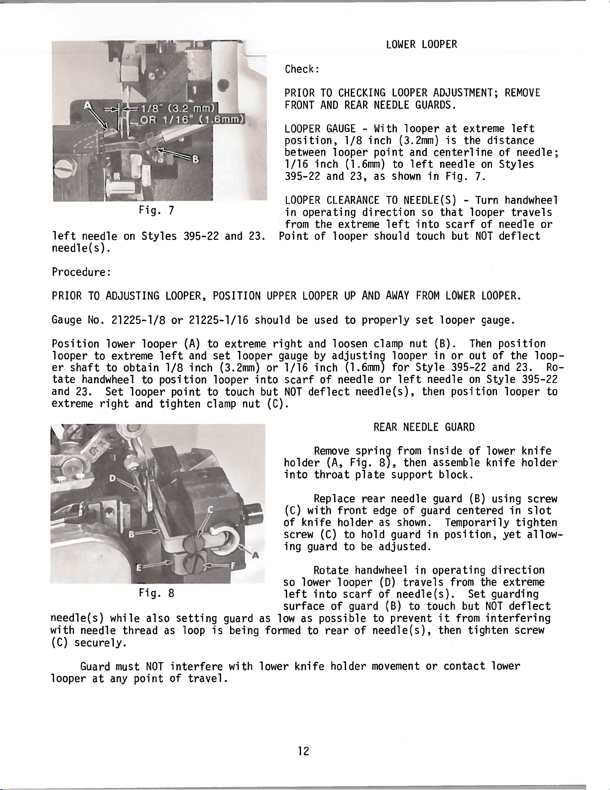
Check:
LOWER
LOOPER
left
needle(s).
Procedure:
PRIOR
Gauge
Position
looper
er
tate
and
extreme
needle
TO
No.
shaft
handwheel
23.
L
on
ADJUSTING
21225-1/8
lower
to
extreme
to
obtain
Set
looper
right
U
Fig.
Styles
looper
to
and
‘
Z
7
LOOPER,
or
left
1/8 inch
position
point
tighten
395-22
POSITION
21225-1/16
(A)
to
set
and
(3.2mm)
looper
to
clamp
and
23.
extreme
looper
touch
nut
UPPER
should
right
or
into
but
(C).
PRIOR
FRONT
LOOPER
position,
between
1/16
395-22
LOOPER
in
from
Point
gauge
1/16
scarf
NOT
TO
AND
GAUGE-With
inch
and
CLEARANCETONEEDLE(S)-Turn
operating
the
of
LOOPERUPAND
be
used
and
by
inch
of
deflect
CIIECKING
REAR
inch
1/8
looper
(1.6mm)
23,
direction
extreme
looper
properly
to
loosen
adjusting
(1.6mm)
needle
needle(s),
LOOPER
NEEDLE
looper
(3.2mm)
point
to
as
shown
left
should
AWAY
clamp
looper
for
or
left
ADJUSTMENT;
GUARDS.
at
is
and
centerline
left
needle
in
Fig.
so
that
into
scarf
touch
FROM
LOWER
set
looper
nut
(B).
in
or out
Style
needle
then
395-22
position
extreme
the
but
distance
on
7.
looper
of
NOT
LOOPER.
gauge.
Then
of
and
on
Style
REMOVE
left
of
needle;
Styles
handwheel
travels
needle
deflect
position
the
23.
395-22
looper
or
loop
Ro
to
needle(s)
with
(C)
looper
needle
securely.
Guard
NEEDLE
REAR
(A,
front
holder
looper
of
rear
holder
spring
Fig.
plate
rear
to
hold guard
be
to
handwheel
scarf
guard
of
Remove
holder
into
throat
Replace
with
(C)
of
knife
screw
ing
so
Fig.
8
while
thread
must
at
any
point
also
NOT
setting
as
loop
interfere
of
travel.
is
guard
being
with
as
formed
lower
left
surface
low
guard
lower
as
to
knife
(C)
Rotate
into
possible
from
then
8),
support
needle
edge
to
needle(s),
movement
of
as
shown.
adjusted.
travels
(D)
of
needle(s).
(B)
to
prevent
inside
guard
in
in
touch
or
assemble
guard
operating
GUARD
of
block.
(B)
centered
Temporarily
position,
from
Set
but
it
from
then
tighten
contact
lower
knife
using
in
yet
direction
the
extreme
guarding
deflect
NOT
interfering
lower
knife
holder
screw
slot
tighten
allow
screw
12
FRONT
NEEDLE
GUARD
Replace
screw
Rotate
then
set
mately
needle(s)
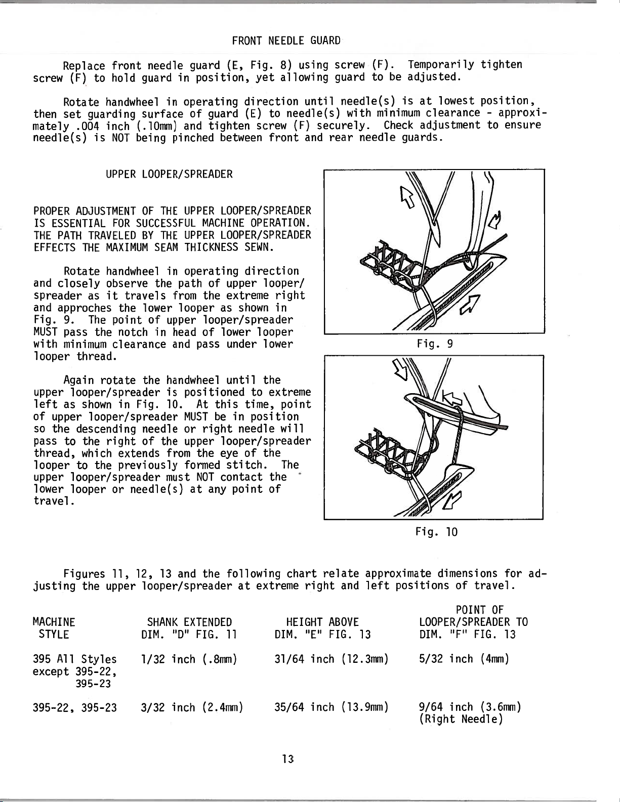
PROPER
IS
ESSENTIAL
PATH
THE
EFFECTS
Rotate
and
closely
spreader
and
approches
Fig.
9.
MUST
with
pass
minimum
looper
front
(F)
to
hold
handwheel
guarding
inch
.004
is
NOT
UPPER
ADJUSTMENT
FOR
TRAVELED
MAXIMUM
THE
handwheel
observe
it
as
travels
the
The
point
the
notch
clearance
thread.
in
in
operating
and
pinched
guard
position,
of
guard
tighten
between
needle
guard
surface
(.10mm)
being
LOOPER/SPREADER
THE
UPPER
OF
SUCCESSFUL
UPPER
THE
BY
THICKNESS
SEAM
operating
in
the
path
from
in
looper
upper
head
lower
of
and
LOOPER/SPREADER
MACHINE
LOOPER/SPREADER
of
the
as
looper/spreader
lower
of
pass
Fig.
(E,
yet
direction
(E)
screw
OPERATION.
SEWN.
direction
upper
extreme
shown
looper
under
8)
allowing
to
front
looper/
right
in
lower
using
until
needle(s)
(F)
securely.
and
screw
guard
needle(s)
with
rear
(F).
to
minimum
needle
Temporarily
be
adjusted.
is
Check
guards.
lowest
at
clearance
adjustment
Fig.
9
tighten
position,
approxi
-
ensure
to
Again
upper
left
of
so
pass
looper/spreader
as
upper
descending
the
to
thread,
looper
upper
lower
to
looper/spreader
looper
travel.
Figures
justing
MACHINE
STYLE
All
395
except
395-22,
395-23
rotate
shown
in
looper/spreader
right
the
the
extends
previously
needle(s)
or
which
11,
the
upper
Styles
the
handwheel
is
positioned
Fig.
10.
MUST
the
or
upper
needle
of
from
formed
must
at
and
13
12,
looper/spreader
SHANK
DIM.
1/32
EXTENDED
“D”
inch
until
this
At
in
be
right
looper/spreader
eye
the
stitch.
NOT
contact
point
any
following
the
FIG.
11
(.8mm)
to
time,
position
needle
of
extreme
at
the
extreme
point
will
the
The
the
of
DIM.
31/64
chart
right
HEIGHT
“E”
inch
relate
and
ABOVE
FIG.
(12.3mm)
approximate
positions
left
13
Fig.
10
dimensions
of
travel.
POINT
for
OF
LOOPER/SPREADER
DIM.
5/32
“F”
inch
FIG.
(4mm)
13
ad-
TO
395-22,
395—23
3/32
inch
(2.4mm)
35/64
inch
(13.9mm)
13
9/64
(Right
inch
Needle)
(3.6mm)
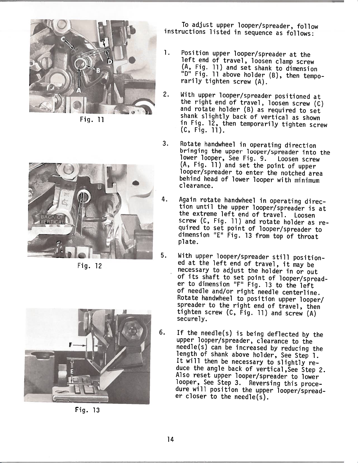
Fig.
11
To
instructions
1.
Position
left
(A,
“D”
rarily
2.
With
the
and
shank
in
(C,
adjust
end
Fig.
Fig.
upper
right
rotate
slightly
Fig.
Fig.
upper
listed
upper
of
travel,
11)
and
11
above
tighten
looper/spreader
end
holder
12,
then
11).
looper/spreader,
in
sequence
looper/spreader
loosen
set
shank
holder
screw
of
back
travel
(B)
of
(A).
as
vertical
temporarily
(B),
,
loosen
required
follow
as
follows:
at
clamp
to
screw
dimension
then
positioned
screw
as
tighten
the
tempo
to
shown
at
(C)
set
screw
Fig.
12
3.
4.
5.
Rotate
bringing
lower
(A,
handwheel
looper,
Fig.
the
11)
looper/spreader
behind
head
clearance.
Again
tion
the
screw
quired
rotate
until
extreme
(C,
to
dimension
plate.
With
ed
at
upper
the
necessary
of
its
shaft
er
to
dimension
of
needle
Rotate
spreader
tighten
handwheel
to
screw
securely.
in
upper
See
Fig.
and
set
to
of
lower
handwheel
the
upper
left
end
Fig.
set
“E”
11)
point
Fig.
and
13
looper/spreader
left
end
of
to
adjust
to
set
“F’
and/or
right
to
the
right
(C,
Fig.
operating
looper/spreader
9.
Loosen
the
point
enter
looper
in
the
notched
with
operating
looper/spreader
of
travel.
rotate
of
looper/spreader
from
top
still
travel,
the
holder
point
Fig.
position
needle
end
11)
of
looper/spread
13
to
centerline.
upper
of
travel,
and
direction
of
upper
minimum
Loosen
holder
of
throat
position
it
may
in
or
the
left
looper/
screw
into
screw
area
direc
is
as
be
out
then
(A)
the
at
re
to
Fig.
6.
13
If
the
upper
needle(s)
length
It
will
duce
Also
the
reset
looper,
dure
will
er
closer
needle(s)
looper/spreader,
can
of
shank
then
angle
See
position
to
14
be
upper
Step
the
is
being
be
increased
above
necessary
back
of
looper/spreader
3.
Reversing
the
needle(s).
deflected
clearance
holder,
to
vertical
upper
to
by
reducing
See
Step
slightly
,See
to
this
looper/spread
by
the
re—
Step
lower
proce
the
the
1.
2.
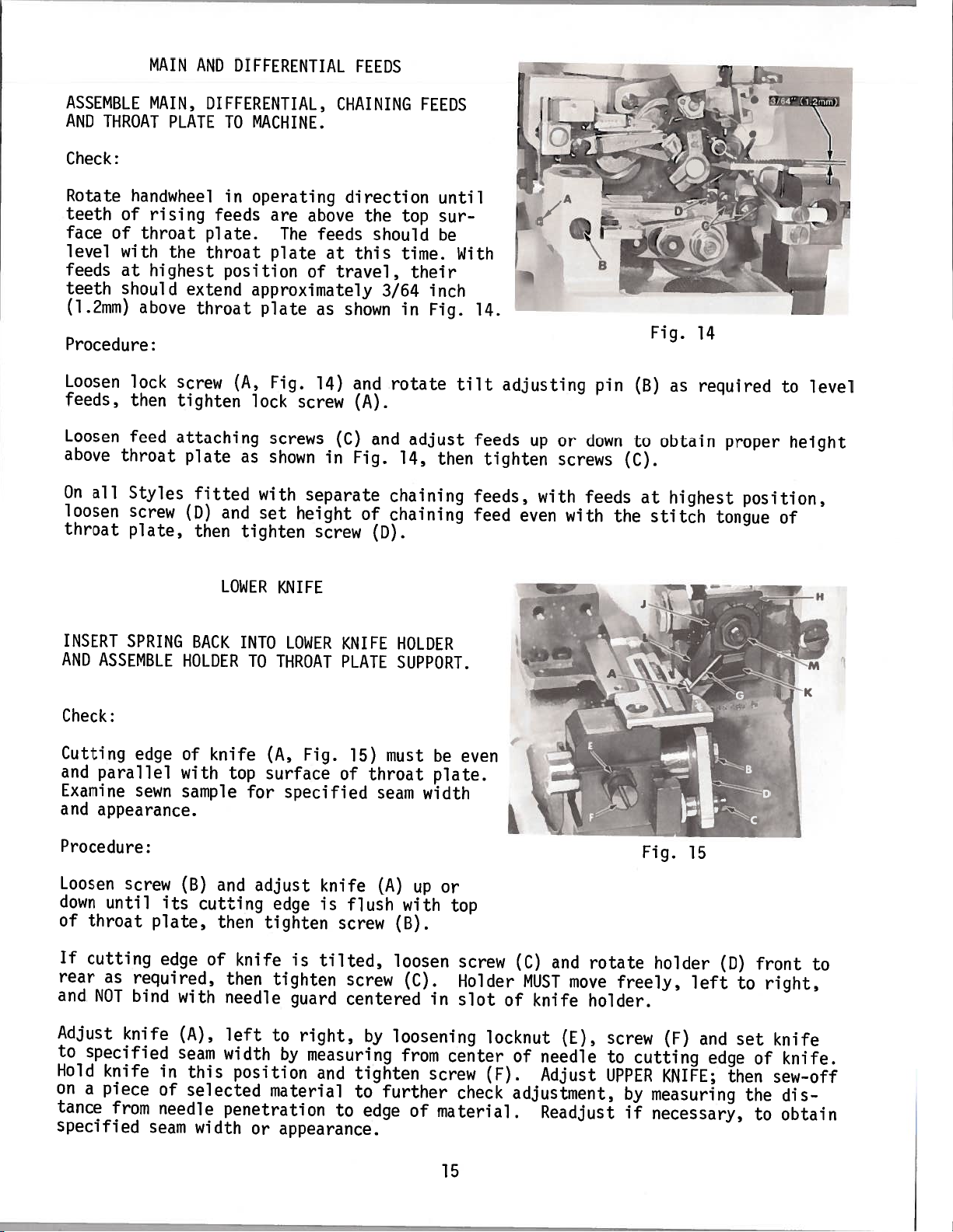
MAIN
AND
DIFFERENTIAL
FEEDS
ASSEMBLE
AND
THROAT
Check:
Rotate
teeth
face
level
feeds
teeth
(l.2iniii)
handwheel
of
of
throat
with
at
should
above
Procedure:
Loosen
feeds,
Loosen
above
On
loosen
throat
all
lock
then
feed
throat
Styles
screw
plate,
MAIN,
PLATE
rising
the
highest
extend
screw
tighten
attaching
plate
(D)
DIFFERENTIAL,
TO
MACHINE.
in
operating
feeds
plate.
throat
are
The
plate
position
approximately
throat
(A,
plate
lock
Fig.
screw
screws
as
shown
fitted
then
and
tighten
with
set
height
CHAINING
direction
above
feeds
at
travel,
of
shown
as
14)
(C)
in
separate
screw
the
this
and
(A).
Fig.
of
top
should
time.
3/64
in
rotate
and
14,
chaining
chaining
(D).
FEEDS
until
sur
be
their
inch
Fig.
adjust
then
With
14.
tilt
feeds
feeds,
feed
adjusting
tighten
even
up
with
or
down
screws
feeds
with
pin
the
(B)
to
(C).
Fig.
at
stitch
as
obtain
highest
14
required
proper
tongue
to
height
position,
of
level
INSERT
AND
ASSEMBLE
Check:
Cutting
and
parallel
Examine
and
appearance.
Procedure:
Loosen
down
until
of
throat
If
cutting
rear
as
and
NOT
Adjust
to
specified
Hold
on
tance
a
knife
piece
from
specified
SPRING
edge
sewn
screw
its
plate,
edge
required,
bind
knife
in
of
needle
seam
LOWER
BACK
HOLDER
of
knife
with
top
sample
(B)
and
cutting
then
of
then
with
seam
(A),
this
needle
left
width
position
selected
penetration
width
INTO
TO
surface
for
adjust
tighten
knife
or
KNIFE
LOWER
THROAT
(A,
Fig.
specified
knife
edge
is
is
tilted,
tighten
guard
to
right,
by
measuring
and
material
appearance.
KNIFE
PLATE
15)
of
throat
flush
screw
screw
centered
by
tighten
to
to
edge
HOLDER
SUPPORT.
must
seam
width
(A)
up
with
(B).
loosen
(C).
loosening
from
screw
further
of
be
even
plate.
or
top
screw
Holder
in
slot
center
check
material.
(C)
MUST
of
locknut
of
(F).
adjustment,
and
move
knife
(E),
needle
Adjust
Readjust
rotate
freely,
holder.
screw
to
UPPER
by
if
Fig.
holder
(F)
cutting
KNIFE;
measuring
necessary,
15
left
and
(D)
edge
then
to
set
the
front
right,
knife
of
knife.
sew—off
dis
to
obtain
to
15
 Loading...