

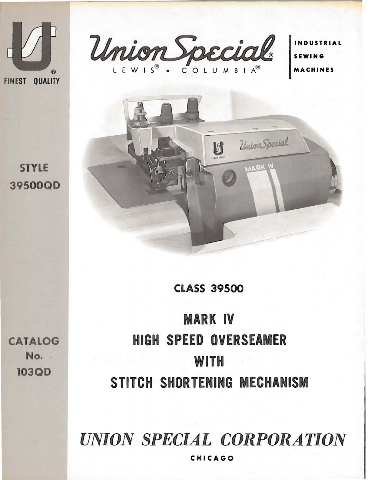
Union Special 39500QD User Manual
INDUSTRIAL
SEWING
FINE
ST
QUALITY
STYLE
39500QD
®
MACHINES
CATALOG
No
. .
103QD
CLASS 39500
MARK
HIGH
SPEED
OVERSEAMER
WITH
STITCH
SHORTENI
UNION SPECIAL
C H
ICAGO
IV
G
MECHANISM
CORPORATION
Catalog
No.
103
QD
(Supplement
ADJUSTING
to
Catalog
INSTRUCTIONS
FOR
AND
LIST
CLASS
OF
Style
39500
PARTS
39500
QD
No.
OPERATING
103
QA)
First
Copyright
by
Union
Rights
Special
Reserved
UNION SPECIAL
INDUSTRIAL
Printed
SEWING
CHICAGO
in
Edition
@
1973
Corporation
in
All
CO
RPORATION
MACHINES
U.S.
Countrie
A.
s
2
October,
1975
IDENTIFICATION
OF
MACHINE
Each
on
the
Style
numbers
Example:
only
minor
ard
Style
Styles
which
differs
39500".
This
junction
are
illustrated.
parts
with
Numbers
position
ordering
This
herein.
Class
given
of
39500.
from
handwheel
Union
machine.
"Style
changes
number.
of
machines
from
catalog
therewith.
their
in
the
of
that
parts.
catalog
It
can
also
References
the
is
Special
Style
have
39500
one
are
machine
numbers
or
QD".
made
Example:
similar
the
Style
is a supplement
Only
On
the
part
first
part
Always
parts
page
numbers,
column
in
the
use
applies
be
applied
to
operator's
away
position
from
is
identified
are
classified
more
letters
Special
Style
in a standard
"Style
number
39500
in
construction
in
that
APPLICATION
to
Catalog
found
opposite
on
the
description
are
reference
illustration.
the
part
specifically
with
Reference
number
to
discretion
directions,
while
operator.
by a Style
as
suffixed,
but
numbers
machine, a "Z"
QDZ".
are
it
contains
OF
CATALOG
No.
103
Style
39500
illustration
and
the
numbers
numbers
listed
the
standard
to
some
such
seated
as
right,
at
the
standard
never
contain
grouped
no
letters.
QA
and
QD,
but
will
number
only,
in
the
second
Style
Special
left,
machine.
number
and
on a name
special.
contain
the
letter
is
suffixed
under a Class
Example:
should
not
be
found a listing
and
should
be
on
of
pieces
merely
never
column.
of
machine
Styles
front,
back,
Operating
the
letter
"Z".
to
used
Style
indicate
of
machines
plate
Standard
"Z".
When
the
stand-
number
"Class
in
con-
39500
of
required.
be
used
as
listed
etc.,
direction
QB
the
the
in
in
are
MARK
Thread,
Pressed
39500
IV
Hi-Styled
Overseaming
Lower
QD
panties,
minimize
seam
and
on
width
differential
stitch
39500
maximum
sewing
50-100%
may
maximum
mum
operation
machine
be
necessary
The
MARK
performance,
recommended
readjustment
Knife,
Light
slips,
the
length
MARK
rated
IV
of
precision
High
Speed,
Machine,
Automatic
to
medium
etc.,
~ossibility
1f8
inch
feed.
and
duty
with
of
(3.17
Maximum
operation.
SPEED
IV
machines
speeds.
may
necessitate
running
to
reduce
have
Varied
cycle
the
is a precision
the
machine
speed,for
the
mechanisms.
STYLE
Single
Differential
Lubricating
machine
knee
ravelling.
mm);
OF
MACHINE
Curved
Feed,
System,
for
controlled
Seam
stitchrange
seaming
recommended
RECOMMENDATION
been
tested
field
conditions,
operating
at a lower
and a longer
machine's
manufactured
should
first
20
speed
be
days
and
operated
of
Blade
Needle,
Trimming
Improved
of
stitch
Specification,
8-30
per
speed
in
their
complete
severity
speed.
than
recommended
by
10-15%.
tested
at
field
operation.
Two
Mechanism
Air
"T"
shirts,
shortening
504-SSa-1;
inch;
8000
cam
R.
stitch
and
cleanliness
When
sewing
1000
machine.
R.
P.
This
Looper,
with
Cooling
polo
mechanism
adjusted
P.
M.
depending
range
operating
stitch
length,
To
M.
below
will
minimize
Three
Spring
System.
shirts,
standard
main
at
their
of
the
from
obtain
maxi-
to
it
3
OILING
CAUTION!
filled
straight
should
before
mineral
be
Machine
sight
gauge
gauge
lines
Machine
main
when
no
It
have
reservoir
To
maintain
operating
case
The
should
oil
is a magnetic
entered
Each
denotes
number,
in
thousandths
size
dles
the
stamped
number
packaged
beginning
used.
is
on
front
when
is
drain
the
Union
kind
represent
and
Oil
was
drained
to
oil
of a Saybolt
filled
with
of
machine.
machine
automatically
filled.
Check
maximum
continuously,
oil
remain
plug
screw
crank
Special
of
on
of
an
screw
designed
case.
shank,
the
inch,
needle
needle
the
sold
by
from
operate.
Oil
viscosity
oil
at
spring
Red
bulb
is
stationary.
lubricated.
oil
daily
recommended
the
oil
must
in
machine
is
located
to
accumulate
It
should
NEEDLES
has
both a type
point,
length,
shank,
midway
between
complete
Union
Special.
machine
capacity
cap
on
No
before
speed
be
for
more
at
back
be
removed
groove,
denotes
symbol
when
of
90
in
oil
oiling
the
and
changed
than
of
possible
and
largest
shank
which
shipped,
of
Class
to
125
top
cover.
level
indicator
is
necessary,
morning
serviceability
at
one
machine
foreign
and
size
finish
diameter
and
eye.
is
given
39500
seconds
Oil
start;
least
year.
near
cleaned
number.
and
other
Collectively,
on
so
reservoir
is
s~
at
100
level
should
is
show
other
add
oil
of
this
every
bottom
six
edge
materials
periodically.
The
details.
of
blade,
the
label
must
ounces.
Fahrenheit
checked
between
than
keeping
as
required.
equipment
months.
of
base.
which
type
number
The
measured
type
of
all
be
A
at
In
may
size
and
nee-
Style
Type
154
single
055/022,
To
sample
label.
Selection
should
Success
of
needles
putation
more
than
Release
Fig.
1)
direction
No.
21388
Again
turn
39500
GAS.
groove,
065/025,
have
needle
needle,
A
complete
of
pass
freely
in
packaged
for
producing
three-quarters
pressure
and
swing
until
needle
AU,
handwheel
QDuses a curved
It
has a round
struck
or
proper
the
groove,
070/027,
orders
the
type
order
needle
through
operation
under
075/029,
promptly
and
would
needle
of
our
highest
of a century.
CHANGING
on
presser
presser
is
furnished
until
at
arm
its
lowest
with
needle
blade
shank,
s:potted,
size
number
read:
size
is
eye
Union
brand
name,
quality
foot
(U)
out
point
machine,
is
at
needle.
round
chromium
The
point,
standard
curved
plated
080/032, 090/036,
and
accurately
should
"1000
Needles,
determined
in
order
Special
~
needles
be
Type
by
to
produce a good
machines
in
materials
NEEDLES
by
turning
of
of
loosen
high
position.
presser
travel.
needle
position;
Using
needle
blade,
and
standard
is
available
040, 044, 049, 054,
filled,
forwarded.
size
154
of
an
empty
Use
GAS,
thread
stitch
can
be
secured
,
Turn
which
foot
handwheel
is
and
workmanship
release
hexagonal
clamp
withdraw
nut
needle.
for
this
package,
description
Size
070/027
used.
formation.
only
backed
bushing
in
operating
socket
about
1/4
style
length,
in
sizes
060.
Thread
by
use
by a re-
for
(AG,
wrench
turn.
is
a
on
11
•
To
left,
insert
position,
nut.
Returnpresser
replace
turn
needle,
needle
in
handwheel
leave
holder
arm
until
(U)
needle
until
holder
to
position;
it
holder
rests
is
at
against
again
re-lockpresser
4
high
at
position
stop
its
low
pin.
point
foot
and,
with
Keeping
of
travel;
release
the
flat
needle
then
bushing
to
the
in
this
tighten
(AG).
THREAD
STAND
After
through
eyelet.
of
tension
back
front,
from
to
through
back
through
Only
are
placed
It
will
of
threading
Before
direction
turning
Be
tension
thread
the
back
The
needle
thread
front.
to
tension
parts
in
simplify
the
beginning
until
presser
sure
discs
comes
hole
and
guide
The
the
middle
front.
post
involved
their
lower
needle
foot
threads,
(J)
and
from
of
thread
upper
(C)
lower
All
three
slot
(K)
in
relative
the
threading
looper
to
thread,
(X)
release
as
in
diagonal
TO
cones
eyelet
looper
from
looper
hole
from
threads
in
tension
threading
positions
first,
is
at
high
bushing
they
come
THREAD
on
cone
(B),
threads
front
thread
to
is
front
then
post
THREADING
are
for
of
this
machine
upper
swing
cloth
position,
(AG)
from
slots
(K)
THE
support
then
are
back,
threaded
to
back,
continue
(G)
shown
clarity.
looper
plate
and
swing
the
tension
in
tension
LOWER
down
then
and
then
and
and
on
in
threading
to
follow
second,
open,
release
presser
LOOPER
(A,
Fig.
through
threaded
through
through
finally
between
through
the
and
turn
pressure
thread
posts
(G).
1),
they
are
the
front
through
the
the
through
the
front
diagram
hole
the
lower
upper
the
tension
thread
(Fig.
recommended
the
needle
hand
wheel
on
presser
arm
(U)
out
guide
(C),
brought
of
upper
hole
hole
back
lower
discs
guide
1).
sequence
third.
in
operating
of
position.
are
between
thread
hole
from
hole
(J),
(M).
Parts
foot
up
to
by
Double
(M,
Fig.
from
Lead
right
thread
handwheel
left,
be
then
threaded
Thread
turn
handwheel
auxiliary
upper
of
(AA),
looper
looper
lead
assembly
through
upper
Thread
handwheel
Insert
(AD),
thread
needle
under
eyelet
end
1).
Then
to
left.
behind
in
operating
thread
easily
upper
looper
thread
thread
thread
(AA).
needle
in
operating
thread
neck
(AC).
of
thread
NOTE:
through
if
looper
until
thread
pull-off
under
Pull
looper
thread
of
lead
thread
fabric
direction
tweezers
TO
point
eyelet
thread
eye
direction
from
top
Thread
and
lead
Thread
guard ( S)
both
eyes
THREAD
thread
of
upper
eyelet
(N)
from
(AF).
neck
of
out
from
TO
through
right
cover
casting;
needle
it
through
through
must
and
until
from
are
in
left
THE
through
looper
(P)
from
left
After
top
pulling
cover
bottom
front
to
THREAD
middle
until
to
left,
from
both
pass
through
heel
left
hand.
UPPER
left
(W)
back
to
right.
of
tube;
back.
THE
eyelet
needle
through
then
front.
the
eyes
in
front
frame
of
lower
to
right.
eyelet
is
all
to
up
upper
casting
push
NEEDLE
of
(X,
down
right
of
lower
of
looper
looper
Left
LOOPER
of
front
the
way
front,
NOTE:
lo.oper
and
tube
front
Fig.
both
eyes
through
eyelet
looper
looper
left.
then
Thread
down
down,
thread
1)
is
of
hole
of
thread
thread
(V)
is
eye
of
thread
Lead
through
thread
through
guide
at
its
needle
in
front
thread
guide
all
lower
guide
must
tube
then
(M).
highest
top
thread
eyelet
pull-off
(T).
the
way
looper
(M).
thread
both
pass
assembly
thread
insert
Then
position.
thread
cover
guide
(R)
(AF).
Turn
to
the
can
Then
through
eyes
in
of
front
tube
thread
turn
eyelet
needle
The
tension
stitch
amount
nuts
(D,
formation.
of
Fig.
tension
1).
Tension
on
THREAD
the
needle
on
threads
TENSION
and
looper
should
threads
be
5
only
is
regulated
enough
to
by
secure
knurled
proper
 Loading...