

CATALOG
NO.
Adjusting
instructions
and
103PA
First Edition
STYLES
39500PA
39500PE
39500PF
39500PP
39500PT
39500PW
illustrated parts list
([)
Class
with thumbscrew adjusted
Finest Quality
39500-Differential
feed overseamers
feed travel
FOREWORD
This technical
new
UNION
SPECIAL
adjusting these
liability
setting
functions
Check
rectly.
designed
The
Adjusting Instructions portion of
for
each
of
the machine.
and
Procedure.
The
Procedure
manual
has
machine. Careful
machines
and
of
will enable
built
the
components
into every
The
The
Check
is
given to explain the proper steps to
been
prepared to guide
attention
related to forming the
text
of the Adjustments
depicts conditions
adjustments are required. Figures are
ence
letters
to point out
specific
items discussed.
Adjustments are presented in sequence
plished.
the function of other
Some
adjustments performed out of sequence
related
parts.
Implementation of preventative maintenance procedures
cant
Whenever
sure to
fically
improvements
it
becomes
insist
for
on
your
in operator productivity
necessary to
genuine
machine
UNION
and
make
SPECIAL
manufactured with utmost precision to assure long
ing service.
you
in the maintenance
to the instructions for operating
you
to maintain the superior performance
UNION
used
repairs
Repair Parts.
SPECIAL
this
manual
machine.
explains in
stitch
is
divided into
when
the parts are adjusted cor-
be
to
illustrate
so
that
a logical progression
by
avoiding costly equipment
or
replace parts
the adjustments using
may
have
an
can
bring about
on
These
parts are designed speci-
detail
and
taken in the event
adverse
your machine,
of
your
and
and
re-
the proper
completing the
two
sections -
refer-
is
accom-
effect
on
signifi-
breakdowns.
be
last-
To
simplify
exploded views.
VIEW
which
illustrated
presents the
on
identification
These
illustrations
mechanisms
this
page
will appear
of
repair
will usually
of the
shaded
Catalog
For
39500
39500
39500
PA
PE
PF
First
Copyright
Union
Special Corporation
Rights Reserved
parts,
machine
in the
No.
103
Styles
Edition
1981
By
In
All
the
mechanisms
be
shown
assembled.
KEY
PA
39500
39500
39500
pp
PT
PW
Countries
are
illustrated
in conjunction with a
The
specific
VIEW.
by
KEY
parts
Printed
May,
In
1981
2
U.S.A.
High
Speed,
ential
feed overseaming machines. Fabric trimmer with spring pressed lower knife.
Independent
automatic
one
and
two
thumbscrew
lubrication
CLASS
curved needles,
adjustments for
system.
Fan
cooled.
DESCRIPTION
two
loopers, three
main
and
differential
and
four thread,
feed
travel.
differ-
Enclosed
39500
woven
PAfabrics.
straight
(2.4mm),
STITCH
SEAM
FEED
MAXIMUM
(Depending
AND
TYPE
..........
SYSTEM
........
SPEED
on
Operation)
LUBRICATION
One
needle,
........
Stitch
seams
l/8
on
inch
pajamas
(3.2mm),
......
low
range
504
.
512
Independent
.
Main
6500
.
7000
Enclosed Automatic Splash
.
Return
capacity
is
8-20
and
women's
5/32 inch
TECHNICAL
SSa-1, Styles
SSa-2, Style
DATA
39500
39500
thumbscrew
and
Differential Feeds.
RPM,
RPM,
Styles
Styles
39500
39500
Pump
MACHINE
machine
S.P.I.
STYLES
for
sewing
Typical application -
underwear. Available
(4mm).
PA,
PE,
PF, PP,
PT
PW
adjustments for both
PF,
PP,
PT,
PW
PA,
PE
System
light
with
to
mediumweight
Seam
Widths: 3/32 inch
For
Oil
seaming
knit or
long
39500
tion -
39500
PE -Same
Seaming
PF -Same
heavyweight knit
T.P.I.
39500
39500
Maximum
39500
1 7 I
64
Each
stamped
The
Stitch
PPPT -Same
shirring
PW -Same
inch (
UNION
in the
serial
Same
6.
7mm)
SPECIAL
number
machine.
as
39500
women's
as
39500
or
woven
range
as
as
is
39500
39500
ratio
as
39500
.
machine
style
plate
is
stamped
PA
except
robes
PA
and
except
fabrics.
8-16
S.P.I.
PF
except equipped with a
PF
except prepared
is
3 to
PP
except
fitted
lingerie.
machine
Also
1.
Available
machine
IDENTIFICATION
carries a style
located to the
in the extension of casting
with
narrow
is
high capacity
sewing
equipped with a
main
for
continuous or
Seam
Width:
has
two
needles. Available
OF
MACHINES
number,
right
which
rear
of
parts.
for
sewing
main
feed
feed
dog
having
intermittent
1/8 inch
on
this
(3.2mm).
class
the machine.
at
the
right
Typical applica-
dog
medium
having
12
to
16
T.P.I.
shirring.
Seam
Width:
machine
is
rear base of
3
TO
PREVENT
THIS
SAFETY
PERSONAL
SYMBOL
INJURY:
SAFETY
A
CAUTION!
INDICATES
YOUR
RULES
PERSONAL
SAFETY
IS
INVOLVED.
-All
-
-
-
mineral
equivalent to
oil
bulb
Clean
Oil
power
justing
Wear
All
shields
DO
NOT
Oil
Machine
level
on
To
magnetic plug of
MUST
sources to the
or replacing
safety glasses.
tamper
capacity
oil
with a Saybolt
at
oil
drain
be
and
guards
with
of
UNION
is
filled
sight
level
changed
indicator
oil
remove
machine
parts.
MUST
safety
Class
SPECIAL
gauge
periodically
shields,
39500
viscosity
specification
with
oil
on
front
will
magnetic plug
any
metallic material
MUST
be
TURNED
be
in position before operating
guards,
LUBRICATION
is
eight
at
spring
of
register
to minimize wear.
ounces
of
90
to
No.
cap
machine.
between
from
THREADING
back
OFF
etc.,
that
while
(227
milliliters).
125
seconds
175.
in top cover. Before operating,
When
proper
red
of
machine
may
gauge
before threading,
machine.
machine
at
oil
near
have
accumulated in crankcase.
100
level
lines.
is
degrees
bottom
oiling,
in operation.
Use a straight
is
reached, red
edge
F.
ad-
This
of base.
is
check
Be
sure
machine
Styles
arm
wheel
No. 660-240
thread, (3) needle thread.
arm
wheel
No.
thread, (3)
39500
Before threading machine; unlock presser foot release bushing,
and
in operating
Thread
Before threading machine; unlock presser foot release bushing,
and
in operating
660-240
Thread
PA,
cloth plate out
are furnished with
machine
cloth
plate
are furnished with
machine
right
is
threaded properly according to threading diagram Fig. 1,
PE,
PF, PP,
THREADING
of
direction
in sequence
out
of
direction
in sequence
needle thread
PT,
or Fig. lA,
DIAGRAM
position
until needle
THREADING
position
until
STYLES
and
machine
as
shown;
DIAGRAM
and
needles are
machine
as
shown;
and
(4)
for
Style
39500
pull
is
to aid in threading.
(1) lower looper thread, (2) upper looper
STYLE
pull upper looper thread tube
to aid in threading.
(1) lower looper thread, (2)
left
4
PA,
uppe
r looper thread tube
at
highest position.
at
needle thread.
39500
PE,
39500
highest position.
PF, PP,
PW
PW.
PT
swing
up.
Thread
swing
up.
Thread
upper
presser
Turn
tweezers
presser
Turn
for
hand-
hand-
tweezers
looper
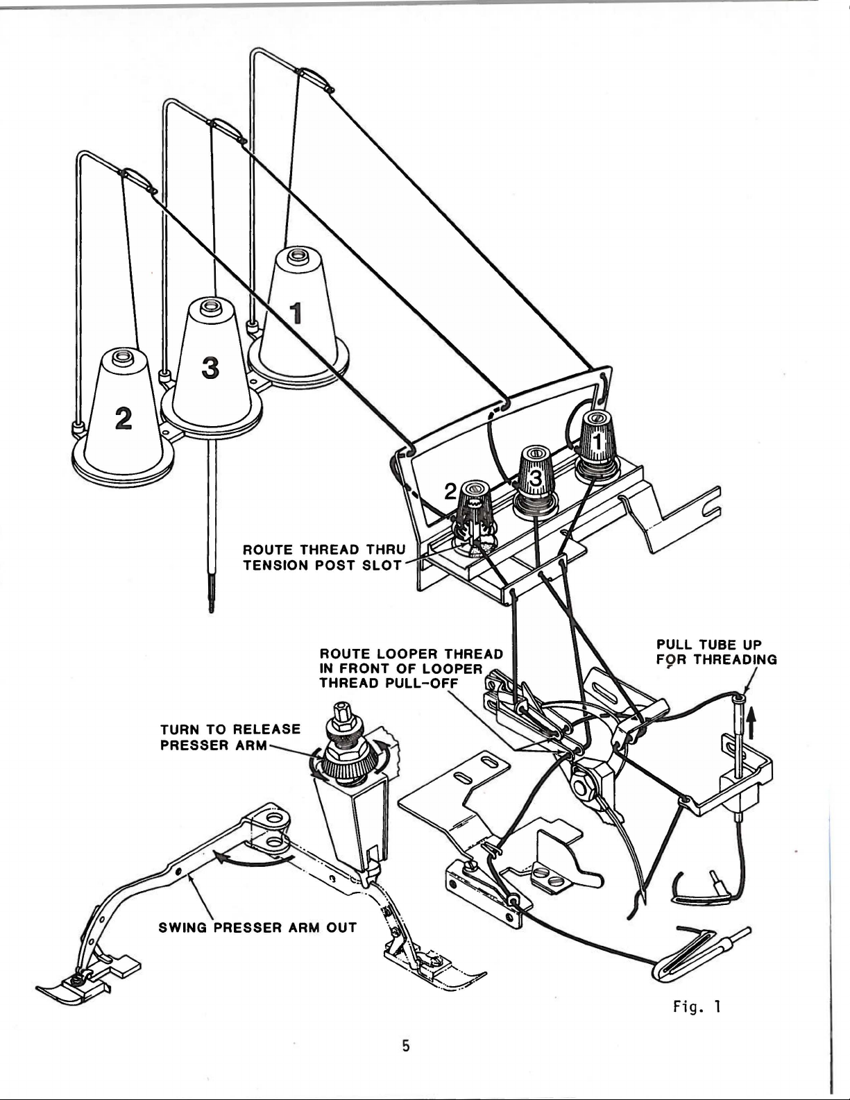
ROUTE
TENSION
THREAD
POST
THRU
SLOT
TURN TO
PRESSER ARM
SWING PRESSER ARM
RELEASE
··
·
~.
ROUTE
IN
THREAD
"'--
OUT
LOOPER
FRONT
PULL-OFF
··"~
~\,~
THREAD
OF
LOOPER
..
A
~··~
~
..
~
5
Fig.
1

TURN
TO
PRESSER ARM -
RELEASE
---.ll"!:j
6
Fig. 1 A
ADJUSTING
INSTRUCTIONS
CLASS
39500
NOTE:
Instructions
stating
of machine, are given
handwheel
right
rotates
end
of machine.
NEEDLES
EXAMINE
TYPE
CHECKS
FORE
LE
NEEDLE
AND
SIZE
RELATED
ADJUSTING
GUARDS.
AND/OR
IS
BEING
TO
NEEDLE(S)
THE
NEEDLE(S),
DISCARD
AND
NEEDLE(S).
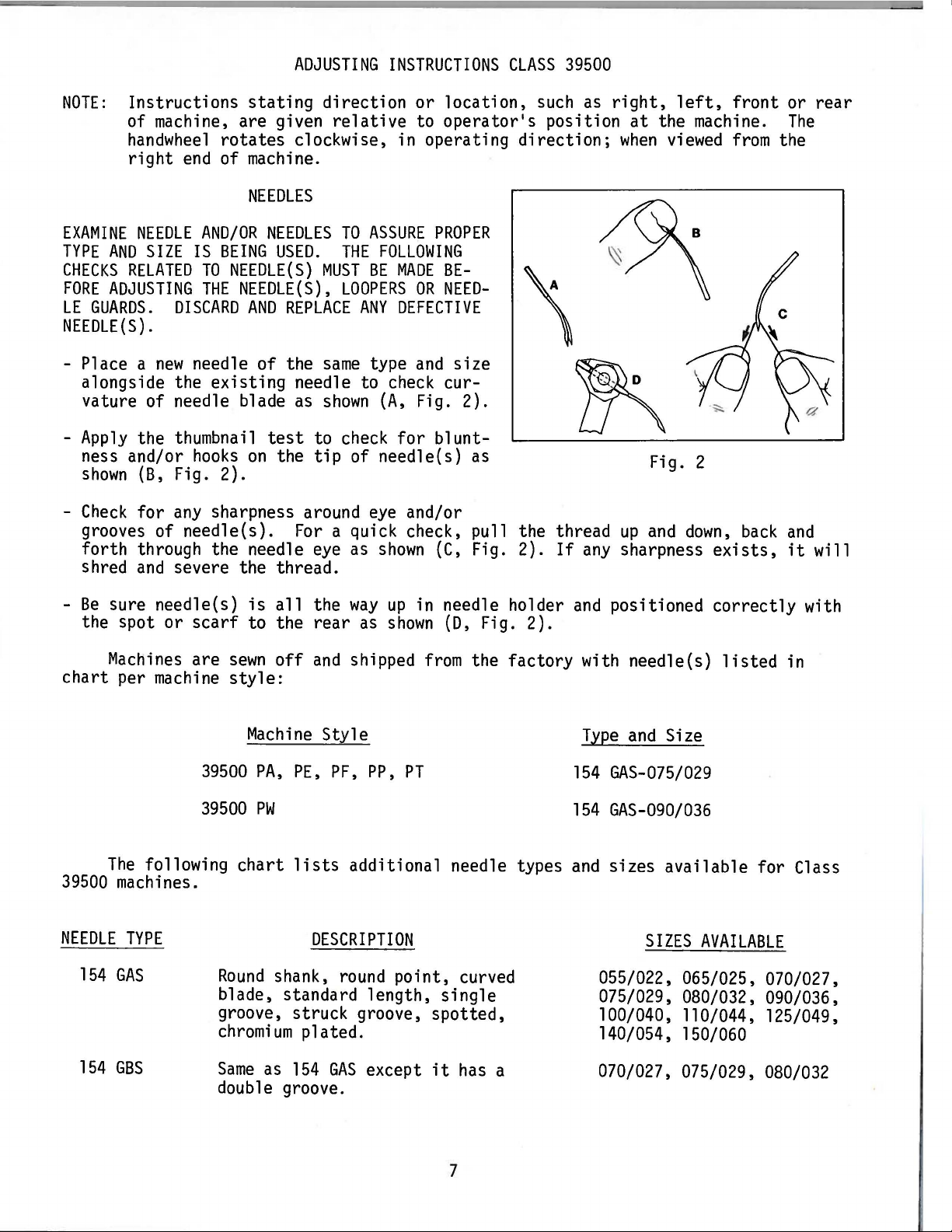
- Place a
alongside the
new
needle of the
existing
vature of needle blade
-
Apply
ness and/or
shown
-
Check
the thumbnail
hooks
(B,
Fig. 2).
for
any
sharpness around
on
grooves of needle(s).
forth through the needle
shred
and
severe the thread.
direction
relative
or
location,
to
operator's
clockwise, in operating
NEEDLES
USED.
REPLACE
as
test
the
TO
ASSURE
THE
FOLLOWING
MUST
same
needle to
shown
to
tip
For
eye
BE
MADE
LOOPERS
ANY
OR
DEFECTIVE
type
and
check
{A,
Fig. 2).
check
for
of needle(s) as
eye
and/or
a quick check, pull
as
shown
PROPER
BENEED-
cur-
blunt-
(C,
size
Fig.
such
as
position
direction;
the thread
2).
If
any
right,
when
left,
at
the machine.
viewed
Fig. 2
up
and
sharpness
down,
exists,
front
from
back
or
The
the
and
it
rear
will
-
Be
sure needle(s)
the spot or
Machines
chart
per
The
39500
NEEDLE
154
machines.
TYPE
GAS
scarf
are
machine
39500
39500
following
groove, struck groove, spotted,
chromium
is
all
the
way
up
in needle holder
to the rear
sewn
off
and
as
shown
shipped
(D,
Fig. 2).
from
the factory with needle(s)
style:
Machine
PA,
PE,
Sty
PF,
le
PP,
PT
PW
chart
lists
additional needle types
DESCRIPTION
Round
shank,
round
point, curved
blade, standard length, single
plated.
and
positioned
correctly
listed
Type
and
Size
154
GAS-075/029
154
GAS-090/036
and
sizes available for Class
SIZES
AVAILABLE
055/022, 065/025, 070/027,
075/029, 080/032, 090/036,
100/040, 110/044, 125/049,
140/054, 150/060
with
in
154
GBS
Same
as
154
GAS
except
it
has
a
double groove.
7
070/027, 075/029,
080/032
NEEDLE
TYPE
DESCRIPTION
SIZES
AVAILABLE
154
GES
154
GHS
154
GJS
154
GLS
To
have
needle orders promptly
needle or type
complete order
Same
as
154
GAS
shorter blunt point.
Same
Same
Same
as
154
ba
11
point.
as
154
tapered b
as
154
GAS
GAS
1 a de.
GAS
ball eye.
and
size
would
number
read 111000
except
except
except
except
and
should
needles,
it
has
a
it
has
a
it
has
a
it
has
a
accurately
be
forwarded.
Type
154
filled,
GAS,
NEEDLE
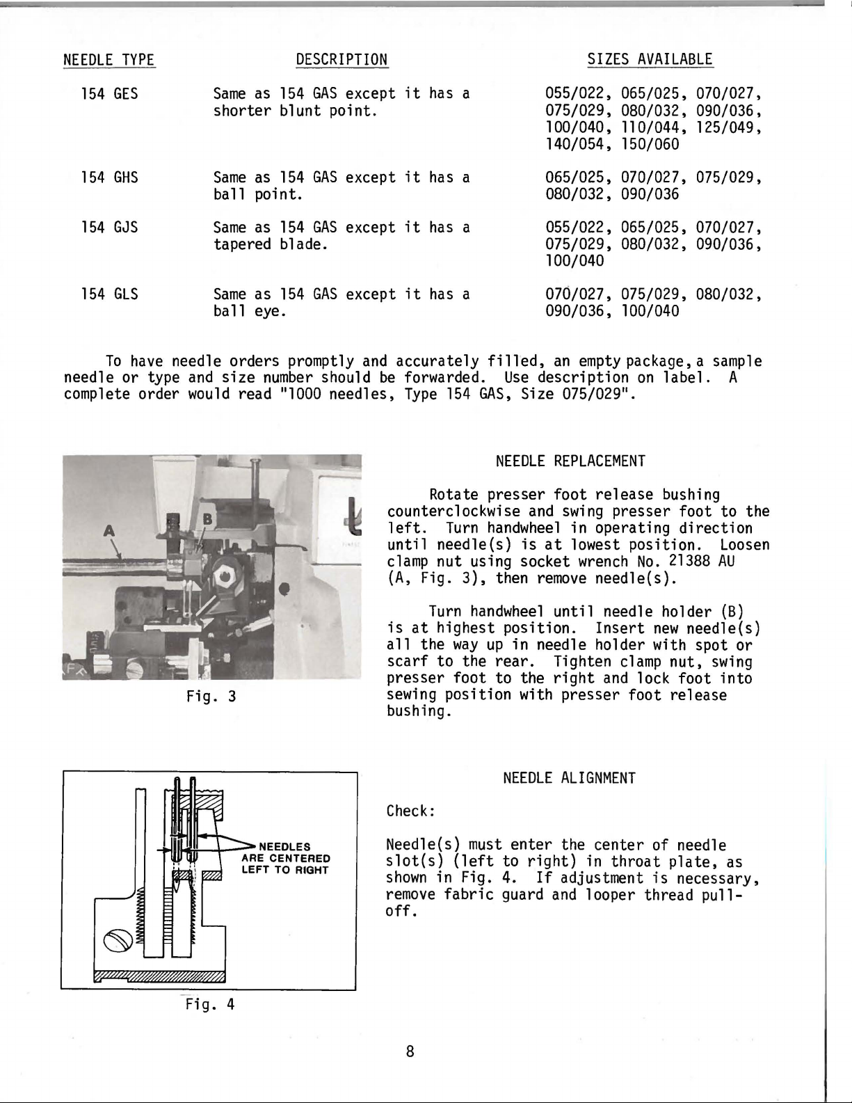
Rotate presser foot release bushing
counterclockwise
left.
Turn
handwheel
until needle(s)
clamp
(A,
nut using socket
Fig.
3),
then
055/022, 065/025, 070/027,
075/029, 080/032, 090/036,
1 00/040,
11
0/044, 125/049,
140/054, 150/060
065/025, 070/027, 075/029,
080/032, 090/036
055/022, 065/025, 070/027,
075/029, 080/032, 090/036,
100/040
070/027, 075/029, 080/032,
090/036, 100/040
an
Use
description
Size 075/029
empty
package, a
on
label.
11
•
REPLACEMENT
and
swing
presser foot to the
in operating direction
is
at
lowest position.
wrench
remove
needle(s).
No.
21388
sample
A
Loosen
AU
Fig. 3
Fig. 4
is
at
all
the
scarf
Turn
handwheel
highest position.
way
up
in needle holder with spot or
to
the
rear.
presser foot to the
sewing
position with presser foot release
bushing.
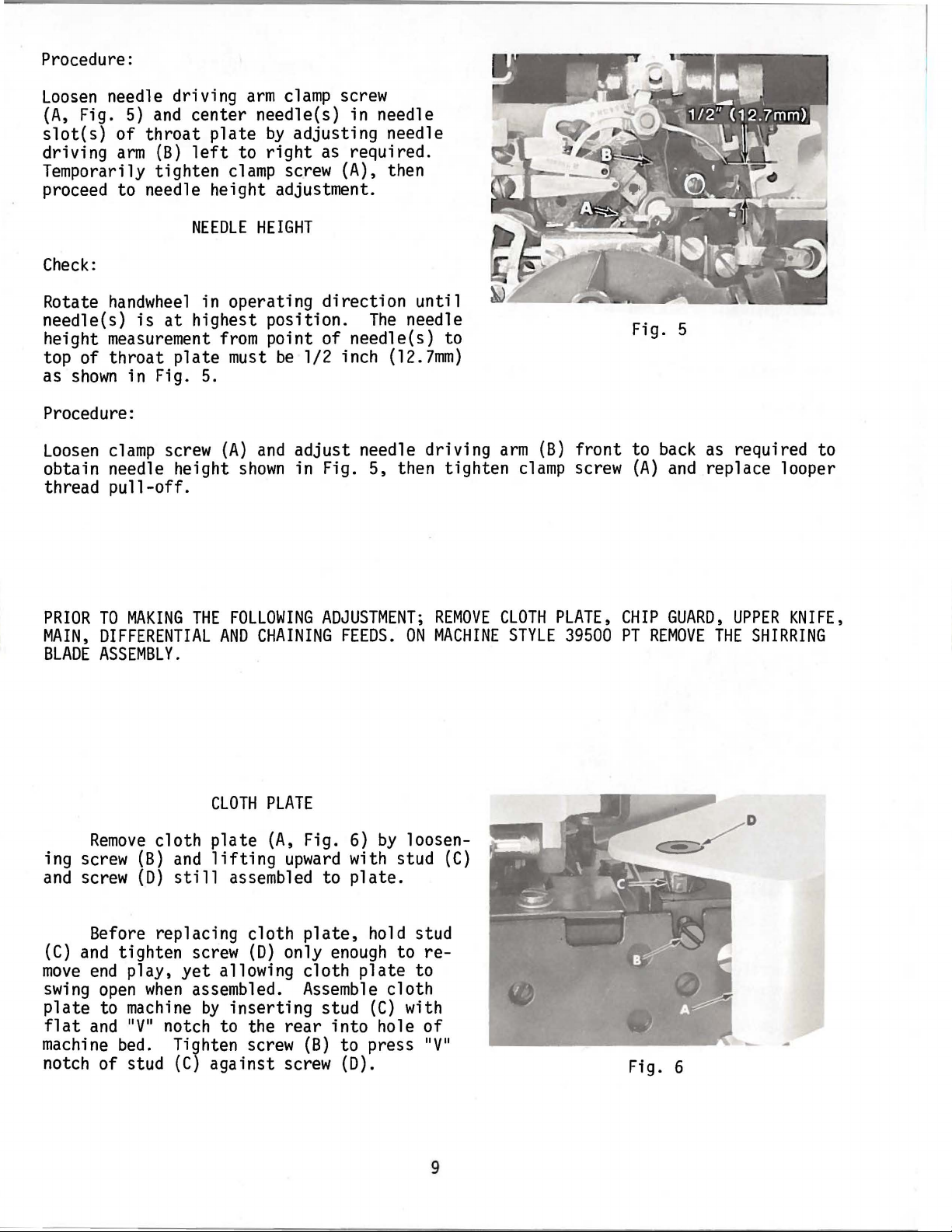
NEEDLE
Check:
Needle(s)
slot(s)
shown
remove
must
(left
to
in Fig. 4.
fabric
guard
enter
right)
off.
until needle holder
Insert
Tighten
right
and
new
clamp
nut,
lock foot into
ALIGNMENT
the center of needle
in
If
adjustment
and
looper thread
throat
plate,
is
(B)
needle(s)
swing
as
necessary,
pull-
8
Procedure:
Loosen
(A,
slot(s)
driving
Temporarily tighten
needle driving
Fig.
5)
and
of
throat
arm
(B)
arm
clamp
screw
center needle(s) in needle
plate
left
by
to
right
clamp
adjusting needle
as
required.
sc.rew
(A), then
proceed to needle height adjustment.
NEEDLE
HEIGHT
Check:
Rotate
needle(s)
height
top of
as
handwheel
measurement
throat
shown
in Fig. 5.
is
in operating
at
highest position.
from
plate
point of needle(s) to
must
be
direction
1/2 inch
Procedure:
Loosen
obtain needle height
thread
clamp
screw
pull-off.
(A)
shown
and
adjust
needle driving
in Fig. 5, then tighten
until
The
needle
(12.7mm)
arm
clamp
(B)
front
screw
Fig.
to
(A)
5
back
and
as
required to
replace looper
PRIOR
MAIN,
BLADE
TO
MAKING
DIFFERENTIAL
ASSEMBLY.
Remove
ing screw
and
screw
{B)
(D)
Before replacing cloth
(C)
and
tighten screw
move
swing
plate
flat
machine
end
play,
open
to
machine
and 11V
bed.
when
11
notch of stud
THE
FOLLOWING
AND
CLOTH
cloth
plate
and
lifting
still
yet
assembled to
allowing cloth
assembled.
by
inserting
notch to the
Tighten screw
(C)
against screw
ADJUSTMENT;
CHAINING
PLATE
{A,
Fig.
upward
plate,
(D)
only
Assemble
stud
rear
(B)
FEEDS.
6)
by
ON
loosenwith stud
plate.
hold stud
enough
to
plate
to
cloth
(C)
with
into hole
to press 11V
(D).
REMOVE
MACHINE
(C)
re-
of
11
CLOTH
PLATE,
STYLE
39500
CHIP
GUARD,
PT
REMOVE
Fig. 6
UPPER
THE
SHIRRING
KNIFE,
9
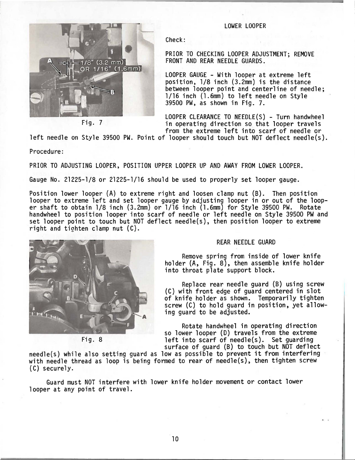
Check:
LOWER
LOOPER
Fig. 7
left
needle
on
Style
Procedure:
PRIOR
Gauge
TO
ADJUSTING
No.
21225-l/8 or 21225-1/16 should
LOOPER,
Position lower looper
looper to extreme
er
shaft
handwheel
set
looper point to touch but
right
to obtain
to position looper into
and
tighten
left
l/8
clamp
39500
(A)
and
inch
nut (C).
PW.
Point of looper should touch but
POSITION
to extreme
set
looper
(3.2mm)
scarf
NOT
deflect
PRIOR
FRONT
LOOPER
TO
CHECKING
AND
REAR
GAUGE -With
position, 1/8 inch
between
1/16 inch
39500
LOOPER
looper point
(1.6mm)
PW,
as
shown
CLEARANCE
in operating direction
from
UPPER
right
gauge
or 1/16 inch
the extreme
LOOPER
be
and
by
UP
used
to properly
loosen
adjusting looper in or out of the loop-
(1.6mm)
of needle or
AND
left
needle(s), then position looper to extreme
LOOPER
NEEDLE
GUARDS.
looper
(3.2mm)
and
to
left
in Fig.
TO
NEEDLE(S) -Turn
left
into
AWAY
FROM
set
clamp
nut (B).
for Style
needle
ADJUSTMENT;
at
extreme
is
the distance
centerline
needle
on
7.
so
that
looper
scarf
NOT
LOWER
of needle or
deflect
LOOPER.
looper gauge.
Then
on
39500
Style
PW.
REMOVE
left
of needle;
Style
handwheel
travels
needle(s).
position
Rotate
39500
PW
and
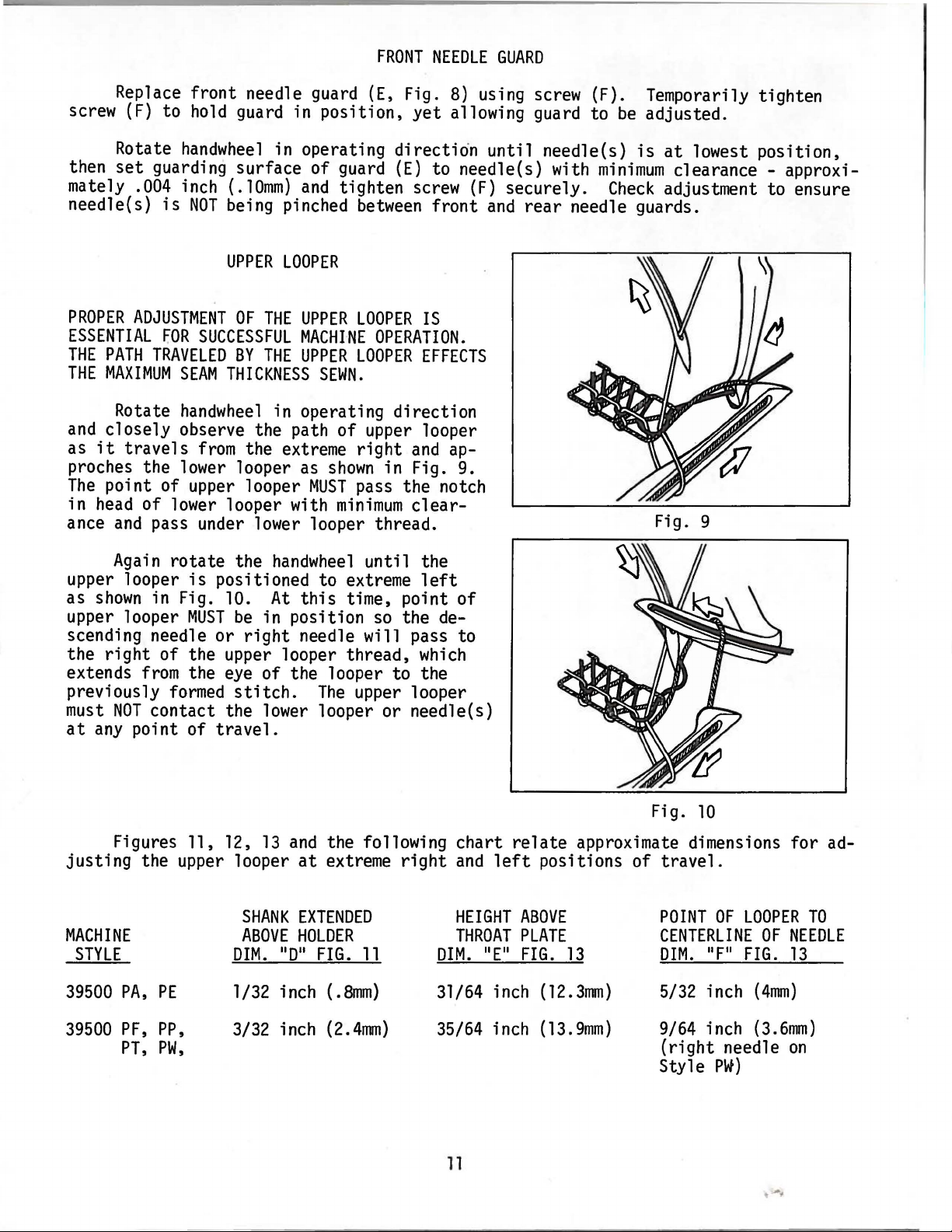
Fig. 8
needle(s) while also
setting
with needle thread as loop
(C)
securely.
Guard
looper
at
must
any
NOT
interfere
point of
travel.
Remove
holder
into
{A,
throat
Replace
(C)
with
of knife holder as
screw
(C)
ing guard to
Rotate
so
lower looper
left
into
surface of guard
guard as
is
being
low
formed
as possible to prevent
to
rear
with lower knife holder
REAR
NEEDLE
spring
Fig.
plate
from
8),
then assemble knife holder
support block.
rear needle guard
front
edge
of guard centered in
shown.
to hold guard in
be
adjusted.
handwheel
scarf
(D)
of needle(s). Set guarding
in operating direction
travels
(B) to touch but
GUARD
inside of lower knife
(B)
using screw
Temporarily tighten
position,
from
yet
the extreme
NOT
it
from
interfering
of needle(s), then tighten screw
movement
or contact lower
slot
allow-
deflect
10
FRONT
NEEDLE
GUARD
Replace front needle guard
(F)
to
hold
screw
Rotate
then
mately
set
.004 inch (.
needle(s}
PROPER
ADJUSTMENT
ESSENTIAL
THE
PATH
THE
MAXIMUM
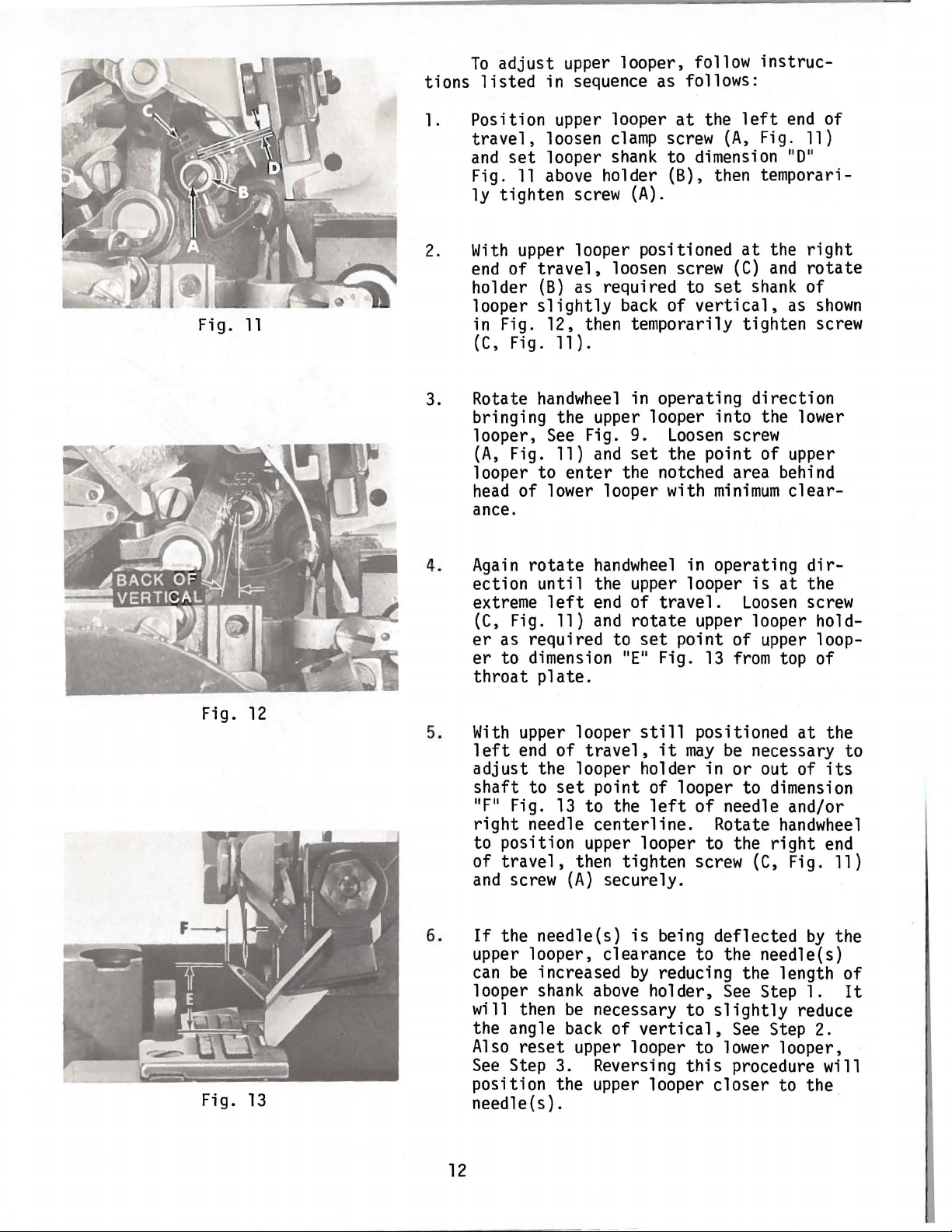
Rotate
and
closely observe the path of upper looper
it
as
travels
handwheel
guarding surface of guard
is
FOR
TRAVELED
SEAM
handwheel
proches the lower looper
The
in
ance
point of
head
of
and
upper
lower
pass under lower looper thread.
guard in position,
in operating direction until needle(s)
lOmm)
NOT
being pinched
UPPER
OF
SUCCESSFUL
BY
and
LOOPER
THE
UPPER
MACHifiE
THE
UPPER
THICKNESS
in operating direction
from
the extreme
as
looper
looper with
SEWN.
MUST
(E,
tighten
between
LOOPER
OPERATION.
LOOPER
right
shown
in Fig. 9.
pass the notch
minimum
Fig.
8)
using screw (F). Temporarily tighten
yet
allowing guard to
(E)
to needle(s) with
screw
(F)
front
securely.
and
IS
EFFECTS
and
ap-
clear-
rear
be
adjusted.
is
at
minimum
Check
clearance - approxi-
adjustment to ensure
needle guards.
Fig. 9
lowest position,
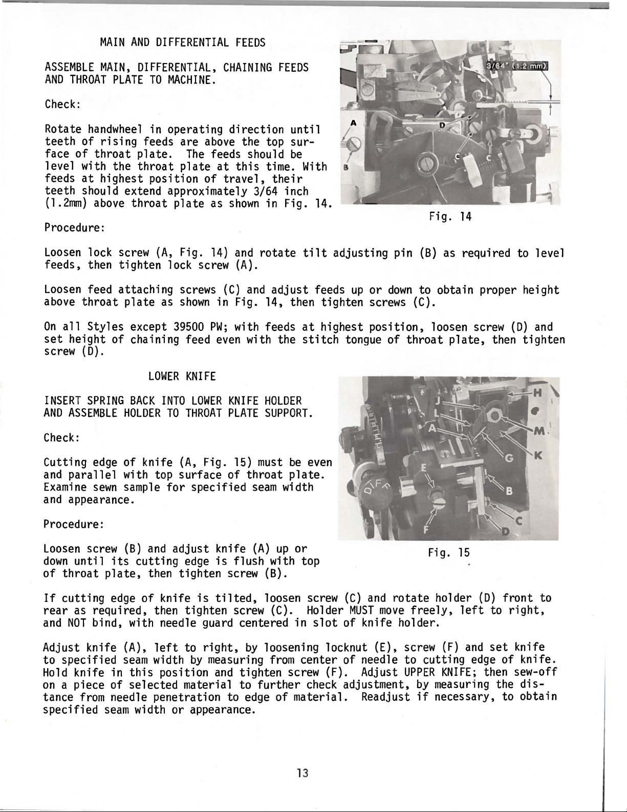
Again
upper looper
as
shown
upper looper
rotate
is
positioned to extreme
in Fig. 10.
MUST
scending needle or
right
the
extends
previously
must
NOT
at
any
of the upper looper thread,
from
the
eye
formed
contact the
point of
travel.
Figures 11, 12,
justing
the upper looper
MACHINE
STYLE
39500
PA,
PE
the
handwheel
At
be
in position
right
needle will pass to
this
until the
time, point
so
of the looper to the
stitch.
lower
13
SHANK
ABOVE
DIM.
l/32 inch
The
upper looper
looper or needle(s)
and
the following chart
at
extreme
EXTENDED
HOLDER
non
FIG.
11
8mm}
(.
left
the de-
which
right
DIM.
31/64 inch
of
relate
and
left
HEIGHT
THROAT
nEn
ABOVE
PLATE
FIG.
10
Fig.
approximate dimensions for ad-
positions of
13
(12.3nm)
travel.
POINT
CENTERLINE
DIM.
5/32 inch
OF
nFn
LOOPER
OF
FIG.
(4nm)
TO
NEEDLE
13
39500
PF,
PT,
PP,
PW,
3/32
inch
(2.4mm)
35/64 inch
(13.9mm)
11
9/64 inch
(right
Style
needle
PW)
(3.6mm)
on
t
...
tions
To
adjust
listed
upper looper, follow
in sequence as follows:
instruc-
Fig.
11
1. Position upper looper
travel,
and
Fig.
ly tighten
2.
With
end
holder
looper
in
(
C,
3. Rotate
bringing the upper looper into the lower
looper,
(A,
looper to
head
ance.
4.
Again
ection
extreme
(C,
er
er
throat
loosen
set
looper
11
above
upper looper positioned
of
travel,
(B)
slightly
Fig. 12, then temporarily tighten screw
Fig.
11
handwheel
See
Fig.
11)
of lower looper with
rotate
until
left
Fig.
11}
as required to
to dimension
plate.
clamp
shank
holder (B), then temporari-
screw
as required to
) .
enter
(A).
loosen screw
back
in operating direction
Fig. 9.
and
set
the notched area behind
handwheel
the upper looper
end
of
and
rotate
set
"E"
at
the
left
end
screw
to dimension "0"
of
Loosen
the point of upper
travel.
point of
Fig.
{A,
Fig.
11)
at
the
right
(C)
and
rotate
set
shank
vertical,
screw
minimum
in operating
is
Loosen
upper looper hold-
13
from
as
clear-
at
upper
top of
of
dirthe
screw
of
shown
loop-
Fig.
Fig.
12
13
5.
6.
With
upper looper
left
end
of
travel,
adjust the looper holder in
shaft
"F"
right
to position upper looper to the
of
and
If
upper looper, clearance to the needle(s)
can
looper
will then
the angle
Also
See
position the upper looper
needle(s).
to
set
point of looper to dimension
Fig.
13
to the
needle
travel,
screw
the needle(s}
be
increased
shank
reset
Step 3. Reversing
centerline.
then tighten screw
(A)
above
be
necessary to
back
upper looper to lower looper,
still
it
left
securely.
is
being deflected
by
reducing the length
holder,
of
vertical,
positioned
may
be
necessary to
or
of
needle and/or
Rotate
{C,
See
slightly
See
this
procedure will
closer
at
out of
handwheel
right
Fig.
by
Step 1.
reduce
Step 2.
to the
the
its
end
11}
the
of
It
12
MAIN
AND
DIFFERENTIAL
FEEDS
ASSEMBLE
AND
THROAT
Check:
Rotate
teeth
face
level with the
feeds
teeth
(1.2mm)
Procedure:
Loosen
feeds, then tighten lock screw
Loosen
above
On
all
set
height of chaining feed
screw
MAIN,
handwheel
of
rising
of
throat
at
highest position
should extend approximately 3/64 inch
above
lock screw
feed attaching screws
throat
Styles except
(D).
DIFFERENTIAL,
PLATE
TO
MACHINE.
in operating
feeds are
plate.
throat
throat
(A,
plate
as
plate
39500
above
The
feeds should
plate
of
as
Fig.
14)
shown
in Fig. 14, then tighten screws (C).
PW;
even
at
CHAINING
direction
the top sur-
this
travel,
shown
and
(A).
(C)
and
with feeds
with the
FEEDS
time.
their
in Fig. 14.
rotate
adjust
until
be
With
tilt
at
stitch
adjusting pin
feeds
highest
up
or
position,
tongue of
Fig.
(B)
down
to obtain proper height
throat
14
as required to level
loosen screw
plate,
then tighten
(D)
and
LOWER
INSERT
AND
Check:
Cutting
and
Examine
and
Procedure:
Loosen
down
of
If
rear
and
Adjust knife
to
Hold
on
tance
specified
SPRING
ASSEMBLE
edge
parallel
sewn
appearance.
screw
until
throat
cutting
as required, then tighten screw (C). Holder
NOT
bind, with needle guard centered in
specified
knife in
a piece of selected material to
from
BACK
HOLDER
of
knife
with top surface of
sample
(B)
and
its
cutting
plate,
edge
needle penetration to
seam
then tighten screw (B).
of
(A},
left
seam
width
this
width or appearance.
KNIFE
INTO
LOWER
TO
THROAT
(A,
for
specified
adjust
edge
knife
position
is
to
by
Fig.
right,
measuring
KNIFE
PLATE
knife
is
tilted,
and
HOLDER
SUPPORT.
15)
must
throat
seam
(A)
flush with top
by
tighten screw (F). Adjust
further
edge
be
even
plate.
width
up
or
loosen screw
slot
loosening locknut (E), screw
from
center of needle
check
of material. Readjust
Fig.
(C)
and
rotate
MUST
move
of knife holder.
adjustment,
freely,
to
cutting
UPPER
by
if
15
holder
(F)
KNIFE;
measuring the
necessary, to obtain
(D)
front
left
to
and
set
edge
of knife.
then sew-off
to
right,
knife
dis-
13
UPPER
KNIFE
REMOVE
ARM.
NEEDLE(S)
ALSO
RE-ASSEMBLE
AND
Check:
At
lowest position the front
inch (.4 -
.8mm)
below
Procedure:
With
upper
knife
(G,
knife firmly against
front
of
Assemble
guard
then tighten nut
tip
lower
(L)
of upper knife cutting
knife, then tighten
knife
clamp
against top surface of
{M).
RE-ASSEMBLE
UPPER
cutting
Fig.
15)
lower
knife, adjust knife holder
UPPER
KNIFE
tip
of upper knife cutting
edge
at
lowest position of travel
edge
screw
(K)
and
chain
upper
KNIFE
IN
HOLDER
HOLDER
AND
INTO
HOLD
SLOT
KNIFE
edge
of lower knife. ·
and
(H)
left
l/64 - l/32 inch (.4 -
(J).
guard
(L)
knife
in position using nut
and
slightly
back
OF
UPPER
FIRMLY
must
extend l/£4 - l/32
KNIFE
IN
POSITION.
while holding upper
to
.8mm)
of
right,
below
(M).
its
to position
cutting
Set chain
cutting edge,
DRIVING
edge
Loosen
If
screw
{F)
desired, the
to enable spring pressed lower knife to
lower
knife
can
be
locked in position
knife holder.
NOTE:
Locking
nut
{E)
must
be
tightened to hold
also serves as a latch pin for cloth
plate.
LOCK
THE
ROTATE
POSITION.
Check:
Right
left
as
edge
shown
by
screw
(F)
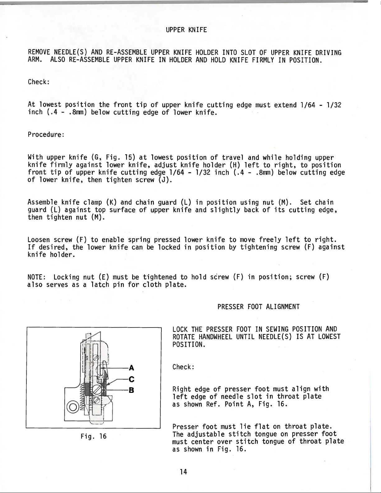
PRESSER
PRESSER
HANDWHEEL
edge
of presser foot
FOOT
UNTIL
of needle
Ref.
Point
move
freely
tightening
in position;
FOOT
ALIGNMENT
IN
SEWING
NEEDLE(S)
must
slot
A,
in throat plate
Fig.
left
screw
screw
POSITION
IS
align with
16.
to
(F)
AT
right.
against
(F)
AND
LOWEST
Fig.
16
Presser foot
The
adjustable
must
as
center over
shown
must
in Fig.
14
lie
stitch
stitch
16.
flat
on
throat
tongue
on
pr.esser foot
tongue of throat
plate.
plate
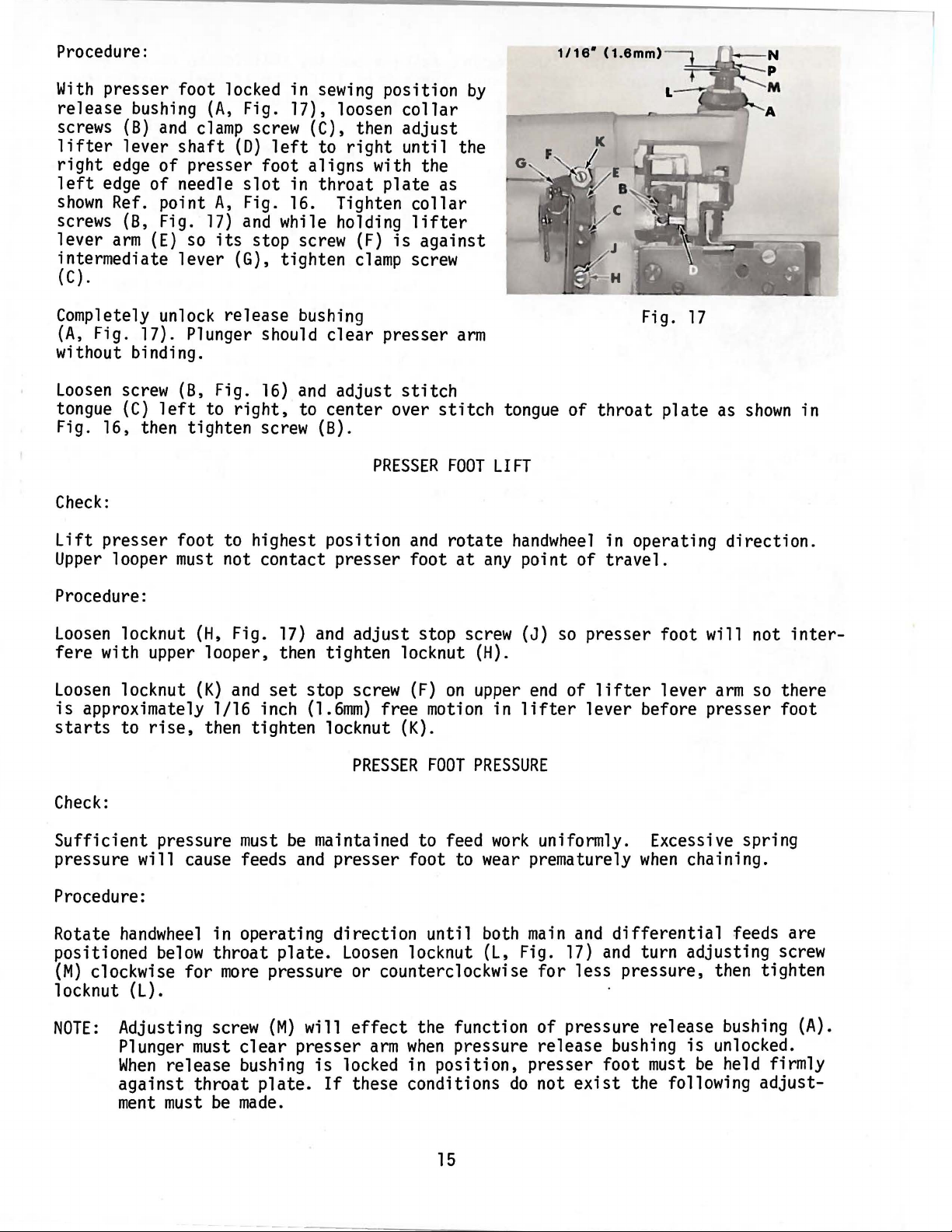
Procedure:
With
release bushing
screws
lifter
right
left
shown
screws (8, Fig.
lever
presser foot locked in
(A,
Fig. 17), loosen
(B)
and
lever
edge
edge
shaft
of
of needle
Ref. point
arm
(E)
clamp
presser foot aligns with the
so
screw (C), then adjust
(D)
left
slot
A,
Fig. 16. Tighten
17)
and
its
in
while holding
stop screw
sewing
to
right
throat
intermediate lever (G), tighten
(C).
Completely unlock release bushing
(A,
Fig. 17). Plunger should
clear
without binding.
Loosen
tongue
screw (8, Fig.
(C)
left
to
right,
16)
and
adjust
to center over
Fig. 16, then tighten screw (B).
Check:
position
collar
until the
plate
(F)
is
clamp
presser
stitch
PRESSER
as
collar
lifter
against
screw
arm
stitch
FOOT
by
tongue of
LIFT
Fig.
throat
17
plate
as
shown
in
Lift
Upper
presser foot to highest position
looper
must
not contact presser foot
Procedure:
Loosen
fere
Loosen
is
starts
locknut
(H,
Fig.
with upper looper, then tighten locknut
locknut
(K)
and
set
approximately 1/16 inch
to
rise,
then tighten locknut
Check:
Sufficient
pressure
must
pressure will cause feeds
Procedure:
Rotate
positioned
(M)
handwheel
below
clockwise
in operating direction
for
throat
more
plate.
pressure or counterclockwise
locknut (L).
17)
and
adjust
stop screw
(1.6mm)
free
(K).
PRESSER
be
maintained to feed
and
presser foot to
Loosen
and
rotate
at
stop screw
(H).
(F)
on
upper
motion
FOOT
PRESSURE
until
locknut
handwheel
any
point of
(J)
in
lifter
work
wear
both
(L,
Fig.
in operating direction.
travel.
so
presser foot will not
end
of
lifter
lever
arm
so
lever before presser foot
uniformly. Excessive spring
prematurely
main
and
17)
for
less pressure, then tighten
when
chaining.
differential
and
turn adjusting screw
feeds are
inter-
there
NOTE:
Adjusting screw
Plunger
When
against
ment
must
clear
release bushing
throat
must
be
made.
(M)
presser
plate.
will
effect
arm
is
locked in position, presser foot
If
these conditions
the function of pressure release bushing
when
pressure release bushing
do
not
15
exist
is
unlocked.
must
be
held firmly
the following
(A).
adjust-

Lock
and
adjust nut
(M)
as
presser foot in position with pressure release bushing
(P)
up
or
down
so
its
shown
in Fig. 17.
Hold
nut
under surface
(M)
in position
is
l/16
and
tighten capnut
(A);
inch
loosen capnut
(1.6mm)
above
(N).
(N)
screw
position,
to the
differential
Fig.
loosen screws
18
feed
maintaining the 1/32 inch
and
underside of presser foot.
Fig.
19
(D)
dog
(.8mm)
and
teeth.
set
shirring
Hold
clearance
SHIRRING
Replace
shirring
sewing
in
shirring
blade in
position
ating direction
highest position.
and
adjust
so
the
flat
on
bracket
inch
of
(.8mm)
shirring
presser
With
blade
shirring
shirring
the feed
(B)
forward
clearance
blade
foot,
then
feed
(C)
dogs
so
blade in position
between
To
ential
(A,
Fig. 19), actuating
lever
shaft
center
dog.
both
(F)
blade
(A
While
collars
to eliminate
shaft,
and
adjusted
(C)
in the
en
its
top
front
center
shirring
feed dog, loosen screws in
(C)
and
loosen tension screw
(E)
to the
shirring
holding blade in position,
(A
then tighten screws in
B).
With
and
in
slot
screw.
BLADE
FOR
blade assembly.
position,
and
turn
until
feed
Loosen
blade
blade
dog
(C)
teeth.
or
rearward to obtain 1/32
between
(C)
and
tighten
still
its
front
and
tighten screws
edge
blade
collar
left
or
blade over
and
B)
against
any
end
the
shirring
position,
of the
shaft
STYLE
39500
PT
lock presser foot
handwheel
dogs
are
screws
mounting
is
level
at
(A,
Fig. 18)
bracket
and
in oper-
Position mounting
top
front
the underside of
screws
at
their
edge
of
shirring
(C)
(A).
highest
is
parallel
over
blade
collar
(B), operating
(D).
right
as required to
differential
shaft
play in the
bracket
shirring
collars
blade properly
set
operating
bracket
and
With
their
(B)
lies
edge
(D)
differ-
Move
feed
thrust
lever
tight-
Tension
by
turning
When
the proper
LENGTH
measured
the distance feeds travel with
wrench
tained,
The
sewn
teeth
per inch of
protruding
Class
-MAIN
No.
21388
hold
actual
39500
(rear)
Y,
furnished with machine.
shirring
blade in position
stitch
seam.
above
machines
and
DIFFERENTIAL
SETTING. STITCH
length produced
This
the
is
throat
are
fitted
determined
plate.
with a feed system having
(front).
tained
and
is
usually
by
16
tighten screw
on
the
shaft
(D).
as the
shirring
collar
amount
number
two
separate feed
blade
can
(G)
with spanner
of tension
of
stitches
their
be
is
obob-
dogs

The
resulting
to
a great extent
The
differential
independent
or
gather
stretch
of
stitch
by
travel
feed travel
the
main
the
fabric
length
feed
stitched.
On
the graduated scale of
(A,
Fig.
20)
longest
stitch
indicates
To
adjust
and
differential
the forward
length
shortest
stitch
thumbscrews
stitch
marking 11L
and
the
length.
length turn both
wise to increase feed travel
wise to decrease feed
travel.
is
of
the
main
can
be
and
is
prior
(B
or
to being
indicator
11
rear
marking 11S
and
counterclock-
determined
feed.
adjusted
used
to
plate
indicates
main
C)
clock-
11
Fig.
20
After desired
differential
an
adjustment
handwheel
way
to the
ance
is
em/kg).
If
differential
the
bed
directly
feeds, also
in operating direction
rear.
obtained.
If
clearance cannot
desired,
feed or.by tightening pressure plug screw for the
accidental changing of
NEEDLE
stitch
is
necessary,
Loosen
Hold
thumbscrews
above
THREAD
length
check
set
nut
(D)
ferrule
the
main
stitch
CONTROL
Check:
The
needle thread
thread
thread
eyelet
ed
eyelet
cam
is
in the screw
lower the
pull-off
set
eyelet
is
controlled
(A,
Fig.
21)
and
(B).
so
the securing screw
slot
to
front
have
The
to back. Raise
the needle thread
barely touch the needle thread
when
tion.
the needle thread in the
eyelet
the needle
Moving
down
and
carrier
the
eyelet
is
up
in
and
stitch,
forward acts in the reverse.
is
obtained
clearance
the feeds to
until
and
the
rotate
in position
be
obtained,
can
be
locked in position
feed
stitch
length during
by
the needle
the needle
needle thread
is
center-
cam
pull-off
its
lowest posi-
back
increases
moving
the
check
between
have
differential
eccentric
and
See
the clearance
the
throat
the
ferrule
same
travel,
feed
plate
is
(E)
torque nut to 19-20
FEED
DRIVE
SEGMENT
by
tightening nut
between
and
the
both feeds.
then turn the
positioned
until
maximum
in.
lbs.
ADJUSTMENT.
(F)
main
feed, located in
regulating screw. This will prevent
machine
operation.
or
Fig.
21
main
all
the
clear-
(22-23
for the
and
If
Procedure:
To
adjust needle thread
described in check.
control,
Hold
eyelet
loosen screw
in position
17
(C)
and
position thread
and
tighten screw (C).
eyelet
(A)
as

Check:
LOOPER
THREAD
PULL-OFF
Clearance
(B)
should
Fig.
21.
between
be
only
looper thread
enough
to ensure proper take-up
pull-off
Procedure:
Loosen
needle driving
(E)
screws
be
sure to take
(E)
shaft
and
rotate
looper thread
until proper clearance
up
all
end
play in needle drive
LOOPER
Check:
When a normal
be a little
amount
slack
of looper thread
when
needle(s)
is
Position guide so the looper thread
with the lower looper
The
auxiliary
set
slightly
upper looper thread guide should
above
at
its
extreme
a horizontal position.
(D,
Fig.
pull-off
is
obtained. Before tightening screws
THREAD
is
at
highest position.
is
held in a
left
CONTROL
drawn,
end
of
upper
be
21)
and
of
looper thread as
lever
shaft.
and
lower looper threads will
straight
travel.
centered in
needle thread
cam
shown
(F)
front
line
to the lower looper,
its
to
back
adjusting
pull-off
in
on
slot
and
Fig.
lower looper thread
tion
and
tighten screw (C).
To
set
frame
its
extreme
in a
straight
NOTE:
Moving
the system
lower looper thread guide
left
end
line
eyelets
and
moving
Procedure:
Loosen
er
set
let
Loosen
eyelet
let
screw
thread
eyelet
(B)
in position
(A,
eyelet
in a horizontal position.
screw (C). Center upper looper thread
(D)
in
so
it
rests
looper thread
eyelet
auxiliary
its
adjusting
above
upper looper thread guide
loosen screw
22
eyelet
of travel
(D)
thread
Center
in
slightly
and
auxiliary
(F)
and
position the guide
to the lower looper. Tighten screw
(B
and
D)
to the
them
forward reduces the
rear
increases the
amount
Fig. 22). Center lower loop(B)
in
its
adjusting
slot
Hold
and
tighten screw
its
adjusting
on
the top surface of lower
eyelet
and
slot
back
and
set
of
lower looper
eye.
upper looper thread guide
slot
and
set
guide
so
a horizontal position.
(E)
in posi-
(G)
and
move
so
the looper thread
lower looper to
is
{G).
amount
of
thread in the system.
of
looper thread in
(A).
eye-
it
Hold
held
and
eye-
(E)
is
18

If
the needle thread loop
set
properly as
seam
grinning
adjustments
this
condition include:
POSITIONING
shown
would
which
in Fig. 23, excessive
result.
should
THE
PURL
Thread
be
checked to
is
NOT
being
control
correct
Lower
-
-
Needle
Lower
Needle
-
edge
unbalance
cated,
edge
under the edge,
looper thread tension too
thread
eyelet
looper thread
thread tension too loose.
If
the purl
of the
between
and
would
improper coverage
occur.
is
fabric
the looper threads
check
control adjustments:
-
Lower
-
Lower
Upper
-
looper thread too
looper thread
looper thread
rear.
-
Upper
looper thread tension too loose.
tight.
too high.
eyelet
NOT
as
shown
If
the purl
too
being
in Fig. 24,
of
far
formed
the
is
being pulled
the following thread
tight.
eyelet
eyelet
too
too
far
far
forward.
on
the
an
is
indi-
seamed
forward.
to the
Fig.
Fig.
23
BOTTOM VIEW
24
If
edge
the purl
as
shown
is
being pulled over the
in Fig. 25, check the following
thread control adjustments:
Upper
-
-
Upper
Lower
-
looper thread tension too
looper thread
looper thread
eyelet
eyelet
too
too
tight.
far
far
forward.
to the
rear.
TOP VIEW
-
Lower
looper thread tension too loose.
Thread
tension
is
regulated
Fig.
25
THREAD
by
the tension assemblies. Turning tension nuts
TENSIONS
clockwise increases tension applied to thread, counterclockwise reduces tension.
Normally, tension
on
the threads should
be
only
enough
to produce a balanced
stitch.
19

Fig.
26
ADJUSTING
1.
2.
3. Thrust the feed control
4.
Assemble
shaft
Thrust feed bars
side of
rear
ring
thrusted against the
Main
with
collars
parts as
(B); including feed bars.
main
of feed bars with
(J)
and
feed control link
main
feed rocker lever
(P
and
illustrated
(C
feed bar
flush against the recess in the
Q).
INSTRUCTIONS
to feed control
and
D)
against
(C)
with
tilt
adjusting pin
bed
shaft
casting
(L)
(A)
and
(N)
FOR
FEED
differential
left
feed bar
and
assuring
and
tightened securely.
main
feed drive lever
to avoid binding
20
that
DRIVE
shaft
thrust
thrust
washer
washer
bed
casting. Collar
and
MECHANISM
(A,
Fig.
26)
and
feed rock
guide
guide (E). Align
(F)
(H)
(M)
secured in position
on
bed.
and
guide pin
is
against retaining
(K)
must
be
in alignment
Thrust
and
thrust
(G).
should
by
left
be

5.
Feed
(R)
in
this
bed
rock
shaft
upwards
position
casting.
(B)
should
and
thrusted against the
by
thrusting collars
be
positioned with the
main
feed
(S)
against thrust
opening
rock
lever
of the retaining ring
(N).
washers
Secure shaft
(T)
against the
(B)
6. Differential feed control link
be
7.
in alignment with
the
differential
lever
(N).
cured in place
Lever
by
A bind could occur in the
(V)
and
lever
is
not properly aligned. Oversize holes are provided in plate
ing
screws
differential
(Z)
to allow repositioning to eliminate bind.
differential
feed rocker lever
(V)
and
rocker lever
their
clamp
main
feed indicator lever
DIFFERENTIAL
1.
2. Rotate
3.
Move
differential
feed rocker lever
differential
is
at
Clamp
the rear
the indicator lever
end
rocker lever
(W).
feed indicator lever
of the scale.
(X)
(U)
and
differential
feed
rocker lever
(W)
must
(W)
thrust against the
can
screws.
feed drive lever
FEED
CONTROL
block
(AA)
to lowest position in
(X)
with
screw
(AB).
feed control lever
(W)
to avoid binding.
be
positioned
(M),
differential
(X)
if
the indicator plate
main
as
required
(Y)
feed control
for
(V)
must
Also
feed rocker
and
se-
(Y)
its
mount-
ADJUSTMENT
differential
counterclockwise until the pointer
DIFFERENTIAL
1.
Move
differential
rocker lever block
clockwise.
2.
3.
Turn
Loosen
4.
Operate
screw
differential
( N).
the
handwheel
feed rocker lever
differential
(AC)
when
the
feed rocker lever
until the feed bar
clamp
feed indicator lever
differential
DIFFERENTIAL
Standard location of the drive pin
feed drive lever
hole of lever
(AE).
(AE).
For
longer
FEED
DRIVE
(AA)
is
screw
(AC).
feed bar
(W)
thrusts against the
FEED
(AD)
is
to
differential
SEGMENT
ADJUSTMENT
to top position
in
its
most
(X)
and
tighten rocker lever
(D)
shows
DRIVE
be
in the
no
LEVER
upper
feed travel
by
rotating lever
rear position.
movement.
main
feed rocker lever
hole of
move
pin
Make
differential
(AD)
clamp
sure
to
(X)
lower
21

TO
REMOVE
Fig.
27
CRANKSHAFT
Crankshaft
1. Drain
base.
2.
Remove
3.
Remove
Remove
4.
5.
Remove
be
can
be
withdrawn
oil
by
removing
top
and
bottom
feed eccentric nut
key
(C).
three counterweights
re-assembled in the proper places.
easier
plug screw located
covers of machine.
(A,
Fig.
(D).
if
these steps are followed:
27)
Identify these counterweights
22
on
and
back
remove
of
machine
the eccentric (B).
near
bottom
so
that
edge
of
they will

6.
Unscrew
tube
7.
Remove
bearing caps
stamped
side of the bearings. Also, screws should
from
8.
Loosen
upper knife driving
clamp
driving
driving lever
drop, allowing
This
crankshaft.
while re-assembling
Step 7 above.
9.
Remove
ner
is
10.
Loosen
move
oil
tube
is
reached through bottom of
caps of bearings
on
both halves
which
at
right
reached through
both halves
they
clamp
nut
is
arm
bearing point
screw
crankshaft bearing. This screw
two
screws
(E)
which
make
to the
sure they are in
were
nut
through top cover.
(C)
removal
Observe
(K,
removed.
(A,
Fig.
arm
left
and
connecting
(J,
same
cap
Fig.
27)
bottom
(L)
in fan
of
cooling fan.
holds crankshaft
on
crankshaft
of
the caps
28)
which
(B).
until
of bearing
as
Access
upper knife
Fig.
27)
precautions
described in
which
of
holds
bed
collar;
bed
casting.
at
their
and
both trademarks should
holds '
to
Draw
rod
(D)
cap
(E).
on
in-
casting.
re-
split
points
original position.
be
bearing
F, G and
re-assembled in the
H.
and
oil
When
Trademarks
be
28
Fig.
pump.
re-assembling
on
same
the
This
are
same
holes
11.
Remove
12.
Loosen
13.
Remove
collar
14. Crankshaft
15.
If
arbor press.
against
16.
Carefully observing reverse of the foregoing operations should simplify re-assembly of crankshaft.
and
17. Before re-assembling, thoroughly clean
Before re-assembling
lubricates
contacts
Coat
leakage.
screw
two
three screws (S); take
(U)
necessary to replace ball bearing (V),
ground
constant
oil
(M);
take
off
pulley
screws (P);
may
be
may
now
In
replacing bearing
thrust
testing
left
crankshaft bearing
shaft.
drain plug with a sealing
The
remove
removed
be
removed.
washer
Checking
for
bottom
wick
pulley (R).
off
at
this
(W).
exploded
binds during re-assembly will also prove helpful.
cover
stands
vertically
cap
(N).
bearing
time.
it
must
view
and
make
sure
is
inserted in hole in casting
compound
retaining
it
should
be
pressed
drawings for location of various parts
dry top
that
on
before re-assembling to prevent
plate
be
pressed
on
carefully
and
bottom
spring pressed
its
spring against
(T);
also,
off
shaft
covers
oil
and
bottom
spacer
until
and
wick
that
on
an
it
seats
gaskets.
which
it
cover.
oil
23

ILLUSTRATIONS
ORDERING
REPAIR
PARTS
This catalog
various sections of the
actual position in the machine.
the parts with
particular
Numbers
tion of
ordering
Component
indenting the descriptions under the description of the
Example:
19
20
At
This will
29126
39544
21
22729
22
22729
23
39544
24
25
39544
the
number
back
is
has
been
arranged to simplify ordering
mechanism
their
view
in the
that
parts.
first
part
parts of sub-assemblies
DF
N
E
D
s
97
u
of
the
facilitate
known.
being
in the
Always
Lower
book
part
number,
shown.
column
locating the
are reference
illustration.
use
the
Looper
Lower
Ball
Screw,
Lower
is
a numerical index
are
shown
On
the
page
description
part
number
which
Bar
Driving Lever
Looper
Screw,
Screw, for connecting
Joint
for
Looper
Connecting
for
Guide
ball
Bar
illustration
so
that
opposite the
and
numbers
Reference
which
can
be
furnished
connecting
Fork
------------------------------------
joint
guide fork
Driving
of
all
and
number
only,
numbers
is
Rod
repair
the parts
listed
and
-----------------------------rod
rod
Lever
the
description
parts.
may
illustration
of pieces required in the
and
merely
should never
in the second
for
repairs
main
Connecting
sub-assembly.
---------------------------
---------------------------
-------------------------
--------------------------parts
be
Rod
shown
when
Exploded
seen in
is a listing
indicate
are indicated
Assembly----- 1
in
only the
be
this
views
their
the posiused
column.
book.
part
of
of
in
by
1
2
2
1
2
1
IDENTIFYING
Where
numbers
USE
Success in the operation of these
SPECIAL
and
scienti.fic principles
durability
TERMS
Prices are net cash
f.o.b.
A charge
TORQUE
Torque
/kilograms.
unless otherwise noted.
must
fications
the construction permits, each
GENUINE
authorized
shipping point.
specifications
be
PARTS
represent the
REPAIR
repair
is
REQUIREMENT
secured
for connecting rods,
parts as furnished
distributors.
are assured.
made
All
straps
as
same
PARTS
and
and
to cover postage
given in
and
tightly
part,
They
are
made
subject to
ParGel
All
Post shipments are insured unless otherwise directed.
this
eccentrics
nuts,
as possible, unless otherwise noted. Special torque speci-
links,
part
is
stamped
regardless of catalog in
machines
by
the
are designed according to the
with utmost precision.
change
and
insurance.
catalog are
must
bolts,
screws,
can
be
Union
without notice.
Special Corporation,
be
tightened to 19-2lin. lbs.(22-24
screws,
etc.,
with the
which
secured only with genuine
Maximum
All
measured
etc.,
are
in inch-pounds or centimeter
without torque
shown
part
shipments are forwarded
on
number.
they appear.
its
subsidiaries
most
approved
efficiency
specifications
parts
illustrations.
Part
UNION
and
em/kg)
24

EXV'LODED
VIEWS
AND
DESCRIPTION
OF
PARTS
25

2
e
26
~
~~6
49
t-47

MAIN
FRAME,
MISCELLANEOUS
COVERS, PLATES
AND
OILING
PARTS
Ref.
~
* 8
* 9
10
11
12
13
13A
14
15
16
17
18
19
20
21
*22
*23
24
25
26
27
28
29
30
31
32
33
34
35
36
37
38
39
40
41
41A
42
43
44
45
46
47
48
49
50
51
52
53
54
55
56
57
58
1
2
3
4
5
6
7
Part
~
22569
39582
39582
22569
53634
22569
39535
39582
22824
22569
39563
667
22565
22565
22571
22569
22569
39578
39578
29477
39568
39568
22743
39594
39594
39535
22569
666-268
39593
666-271
660-506
56393
56393
666-280
39593
22569
39593
660-243
39593
39582
22653
39582
51295
39595
39595
22586
39593
39593
22569
74
22806
22572
39582
39582
39582
39501
39501
39532
90
39501
138
39578
22657
BD
BU
J
c
c
p
BF
D
H
D-8
s
E
K
D
T
u
GW
G
J
s
T
M
B
K
G
v
L
D
J
H
F
D-4
AY
B
R
D
c
E
A
A
AZ
BA
XE
DL
DLB
A
K
F
-D-12
Screw,
Gasket, for rear cover
Rear
Screw,
Washer,
Screw,
Main
Oil
Screw,
Screw,
Needle
Dowel
Set
Spot
Oil
Screw,
Screw,
Chip
Chip
Upper
Oil
Oil
Guide, for
Screw,
Felt
Oil
Oil
Retaining Ring,
Porex
Spring, for
Oil
Spring, for
Screw,
Oil
Oil
Oil
Base
Screw,
Gasket, for
Isolator,
Isolator,
Isolator,
Screw,
Oil
Oil
Screw,
Plug
Screw,
Screw,
Bottom
Gasket, for
Bottom
Cloth
Cloth
Latch
Screw,
Cloth Plate Stud
Screw,
Cloth Plate Fabric
Screw,
for cloth plate stud
Cover
-------------------------------------------------------------
for rear cover
for
main
for
Feed
Bar
Shield,
for
for
Thread
Pin
--------------------------------------------------------------
Screw,
rock
shaft
Screw,
Drain
Plug
for
for
Guard,
Guard,
Looper
Thread
Thread
Screw,
Filter
Filter
for
Pad
---------------------------------------------------------------
Tube,
tygothane
Tube,
brass
Filter,
Tube,
tygothane
for
oil
Pump
Tube
Seal
Ring,
Sight
Gauge
Plate Extension
for base plate extension
for Styles
for Styles
for Style
for
Gauge
Gauge
bottom
Indicator
Float
for
bottom
Screw,
for
bottom
for
bottom
Cover
Cover
Plate,
Plate,
Plate
for
latch plate latch spring
for cloth plate fabric guard
for cloth
feed bar
main
feed bar
Thrust
lower
lower
needle thread
for upper looper thread tube assembly
oil
chip guard
Screen
Pad
differential
differential
oil
oil
bottom
for
bottom
Latch
------------------------------------------------------
oil
Pull-off Eyelet
------------------------------------------------------------
for
upper looper
--------------------------------------------------------sight
for
Styles
for Style
Thread
Tube
-------------------------------------------------------
Tube
Tension Spring
for
thread tube tension spring
------------------------------------------------------
---------------------------------------------------------
-------------------------------------------------------for
for
oil
tube
tube
tube spring
---------------------------------------------------------for
oil
--------------------------------------------------------
cover
cover
-------------------------------------------------------cover
machine
cover
cover plate
Plate
----------------------------------------------------cover plate
-----------------------------------------------------------
for
Styles
for
Style
Spring
------------------------------------------------------Guard
plate
Description
--------------------------------------------
-------------------------------------------------
-------------------------------------------------thrust
thrust
Guide
shield
pull-off
gauge
--------------------------------------------------
39500
39500
Tube
Assembly
feed bar
feed bar guide
---------------------------------------------------oil
tube
tube
---------------------------------------------
---------------------------------------------------
----------------------------------------------------
---------------------------------------------------
---------------------------------------------
sight
---------------------------------------------------
-----------------------------------------------
39500
PA,
39500
PA,
39500
----------------------------------------------------
PW
------------------------------------------------
-----------------------------------------------bed
plate
39500
39500
-----------------------------------------------
-----------------------------------------------
-------------------------------------------------
guide
guide
---------------------------------------------
--------------------------------------------
------------------------------------------
rock
--------------------------------------------PA,
PW
-----------------------------------------
----------------------------------------
-------------------------------------------
gauge
----------------------------------------
PE,
PE,
-------------------------------------------
--------------------------------------------
------------------------------------------
------------------------------------------
-----------------------------------------
PA,
PW
----------------------------------------
---------------------------------
----------------------------------
eyelet
shaft
PE,
--------------------------------------
---------------------------------------
-------------------------------------
PF,
PF,
PE,
-------------------------------
and
upper looper
--------------------------------
PF,
PP
and
PT
---------------------
-----------------------------
---------------------------------
PP
and
PT
PP
and
PF,
PP
------------------------------------
------------------------------------
-----------------------
PT
-----------------------
and
PT
--------------------
Amt.
~
1
1
1
4
2
2
1
1
2
1
1
2
2
1
1
1
2
1
1
1
1
1
1
1
1
2
2
1
1
1
1
1
1
1
1
1
1
1
1
1
2
1
2
2
4
1
1
1
11
1
1
5
1
1
1
1
1
1
2
1
2
1
1
*
Used
on
earlier
model
machines.
27

28

CRANKSHAFT
MECHANISM
AND
BUSHINGS
Ref.
No.
1
2
3
4
5
6
7
8
9
10
11
12
13
14
15
16
17
18
19
20
21
22
23
24
25
26
27
28
29
30
31
32
33
34
35
36
37
38
39
40
41
42
43
44
45
46
47
48
49
50
51
Part
No.
22569
39536
39536
39555
39573
39555
39552
39573
39552
39544
39590
39590
666-94
22747
39591
39591
39590
97
39591
39590
77
39590
660-204
660-443
39591
22894
22565
29477
29477
29477
22587
22596
22768
51-228
39541
30-106
C067
39536
22769
39521
39521
95
22569
39590
39590
39590
660-268
39590
39590
39591
87
39594
Description
Screw,
CD
BY
P
K
R
U
AA
P
X
Differential
Differential
Foot
Upper
Foot
Needle
Upper
Needle
Lower
T Crankshaft Bushing, inner
U Crankshaft Bushing,
Oil
B
Screw,
A Crankshaft Counterweight,
K Crankshaft Counterweight,
V
Split
A
for
Lifter
Knife
Lifter
Driving
Knife
Driving
Looper
Wick
cloth
Shaft Bushing,
Driving
Shaft Bushing,
Driving
and
plate
Feed
Rocker
Feed
Rocker
Arm
Arm
Bar
Bushing
Spring, for crankshaft bushing
for counterweights
Bearing
Screw,
and
for
Oil
split
stud
Arm
Crank
Arm
Crank
left
Pump
bearing
-------------------------------
Shaft Bushing,
Shaft Bushing,
left
Bushing,
right--------------------------
Bushing,
Bushing,
Bushing,
---------------------------------right---------------------------
----------------------------------
---------------------------------
middle
left
--------------------------------
B Crankshaft Counterweight, right
P
Q Set Screws,
X Crankshaft Bearing, inner
H
0 Spot
F Spot
LS
LT
MC
M
H
C
A
E
BL
B
0 Pulley
G Pulley
B
H Ball Bearing Retaining Plate
S
R Ball Bearing
G Ball Bearing
J Thrust
L
U
N
Oil
Slinger Collar
Oil
Seal
Oil
Seal
Fan
Collar
Screw,
Screw,
Crankshaft
Crankshaft
Needle
Ring
Ring
-----------------------------------------------for fan
for
Assembly,
Assembly,
Driving
Screw,
Screw,
Screw,
Blk.
Blk.
Vent
Feed
Wood
Cork
Nut,
Screw,
Plug
--------------------------------------------
Driving Eccentric
Plug
-----------------------------------------
Plug
--------------------------------------------
for
crankshaft
for pulley
Cap
------------------------------------------------
----------------------------------------------------
Set
Screw,
Spacing
Screw,
for
Collar
for
ball bearing
--------------------------------------------
Stop
Crankshaft Ball Bearing
Housing
Fan,
Screw,
Oil
Splasher
Washer
for
for
chamber
---------------------------------------------
oil
splasher
----------------------------------------------
----------------------------------------
for
oil
slinger
right
----------------------------------------
---------------------------------------collar
--------------------------------
crankshaft bearing inner,
for
Styles
for
Styles
Arm
Crank
for
needle driving
for
needle driving
for
needle driving
and
Key
----------------------------------
cap
-------------------------------------
pulley
--------------------------------
housing
------------------------------
Collar
----------------------------------
-----------------------------------
--------------------------------------
cooling
----------------------------------
-----------------------------------
left
middle
-------------and
right
--------------------------left
---------------------
left
--------------------
right
--------------------
right
-------------------
---------------
--------------------
----------------------------
and
oil
pump
----------------
---------------------------
collar
-------------------
---------------------------
39500
39500
PA
PF,
Connecting
arm
arm
arm
right
and
PP,
connecting
crank
connecting
-----------
PE
-----------
PT
and
Rod
Assembly
rod
------------rod
---------------------------
---------------------------
--
-
-----
PW
---
---pin- 1
-
--
Amt.
~
1
1
2
1
1
1
1
1
1
1
1
1
1
6
1
1
1
2
1
1
2
1
1
1
1
2
1
1
1
- 1
2
1
1
1
1
1
1
1
1
1
2
3
1
1
1
1
1
1
1
1
1
29

\
\
\
\
\
'
'>
~https://manualmachine.com/
TORQUE
TO
19-20
in.
(22-23
em/kg)
lbs.
46
30

FEED
DRIVE
MECHANISM
Ref.
~
1
lA
2
3
4
5
6
7
8
9
10
11
12
13
14
15
16
17
18
19
20
21
22
23
24
25
26
27
28
29
30
31
32
33
34
35
36
36A
36B
36C
37
38
39
40
41
42
42A
43
43A
43B
43C
44
45
46
47
48
49
50
51
52
Part
No.
39536
AN
22651
AB-3
660-467
39536
BE
39536
AM-247
39536
AM-248
39536
AM-249
39536 AY39536 AY39536 AY22733
62244
A
51236
A
35751
G
22572
B
39536
AL
40-13
22852
A
39536
AR
80557
22852
A
39536
CM
39535
L
22597
A
39536
BX
39534
s
39535
J
39535
N
39534
T
39536
AX
39536
BA
39536
BB
39536
AU
77
39540
E
39540
F
22894
AA
22760
E
39536
E
39536
BU
39536
BE
39526
AP
39526
AE
39526
BP
39526
BH
39526
w
22528
39535
K
98
A
39536
J
39536
BC
39505
L
39505
BB
39505
AW
39505
BP
39505
AY
39505
BA
39505
BL
39505
WA
94
22747
39540
G-13
39536
BW
39536
E
39536
BU
39538
9937
39536
AW
9
247
248
249
Description
Feed
Drive
Rock
Shaft
Set Screw, for feed drive
Truarc Ring, for feed drive
Stud,
for
main
Main
Feed
Main
Feed
Main
Feed
Differential
Differential
Differential
Set Screw,
Thrust
Link
Collar,
Differential
Differential
Main
Feed
Screw, for feed adjusting pin
Feed
Main
Feed
Guide
Differential
Differential
Differential
Differential
Differential
Differential
Differential
Screw, for
Nut,
Differential
Differential
Differential
Differential
Differential
Differential
Differential
Screw,
Guide
Screw,
Stud, for
Main
Chaining
Chaining
Chaining
Main
Main
Main
Main
Main
Screw,
Screw,
Main
Main
Nut,
Main
Feed
Nut,
Main
Washer,
Pin, for
for
Screw,
Washer,
Screw,
Washer,
Screw,
Feed
Adjusting
Bar
Feed
Bar
Pin,
Screw,
Spot
for
for
Block,
for
Feed
Feed
Feed
Feed
Feed
Feed
for
for
Feed
Feed
for
Feed
Lift
for
Feed
feed drive
Segment
Segment
Segment
Feed
Feed
Feed
for
differential
feed drive
for
Feed
for
for
Feed
for
for
Drive
Pin
Thrust
Bar
-------------------------------------------------------------------
Guide
Block
for
differential
Feed
Feed
Feed
Feed
Feed
for differential
Feed
Feed
Screw,
differential
differential
Feed
Feed
Feed
Feed
Feed
Feed
Feed
differential
for
guide block
main
feed bar
Drive Stud Ferrule
Feed
Dog,
Feed
Dog,
Feed
Dog,
Dog,
marked
Dog,
marked
Dog,
marked
Dog,
marked
Dog,
marked
main
chaining feed
Eccentr
Drive Connecting
main
feed drive connecting
Drive Eccentric Ferrule
Block
main
feed bar stud
Drive
-----------------------------------------------------------
Sliding Block,
Sliding Block,
Sliding Block,
Segment
Segment
Segment
for
feed drive
collar
Drive
differential
differential
Drive
differential
differential
Segment
--------------------------------------------------------------
Washer
Bar
Drive
Control
Drive
Drive Connecting
Eccentric, for Styles
Eccentric, for Styles
for
Drive
Bar
Dog,
Dog,
Dog,
Dog,
Dog,
main
marked
marked
marked
feed
ic,
----------------------------------------------------------------Link
segment
Sliding Block,
Sliding Block,
Sliding Block,
differential
feed drive
rock
----------------------------------------------------.-----Lever
Segment
---------------------------------------------------------
----------------------------------------------------------
------------------------------------------------------------
----------------------------------------------------------Link
Link
Link
differential
feed control link
feed bar stud
Eccentric Ferrule
Drive
16
teeth per inch,
12
teeth per inch,
16
teeth per inch,
16
teeth per inch,
12
teeth
feed
feed bar
----------------------------------------------------------
--------------------------------------------------------"V",
"PO
"FK",
"FW",
"PH",
"PC",
"QX",
"WA",
dog
-------------------------------------------------------dog
marked
Rod
------------------------------------------------------------
rock
shaft
rock
shaft
----------------------------------------------marked
marked
marked
feed
rock
shaft
shaft
-----------------------------------------------
---------------------------------------------------
feed drive lever
feed drive lever
-------------------------------------------------
feed drive
feed drive
and
feed bar guide pin
feed bar
----------------------------------------------------
--------------------------------------------------
Pin
------------------------------------------------
Rod
feed drive connecting
feed eccentric
Stud
------------------------------------------------
per inch, for Style
dog
------------------------------------------------
--------------------------------------------------
---------------------------------------------------16
teeth per inch,
",
16
teeth per inch,
16
16
12
16
16
12
"EH"
-----------------------------------------------------
teeth
teeth per inch,
teeth per inch,
teeth per inch, for Style
teeth per inch,
teeth per inch,
----------------------------------------------------
------------------------------------------------
--------------------------------------------------
-----------------------------------------------
---------------------------------------
-----------------------------------------"G",
.247 inch
"H",
.248 inch
"J",
.249
marked
marked
marked
segment
----------------------------------------
lever-------------------------------------
segment
segment
--------------------------------------------
-----------------------------------------39500
39500
---------------------------------------------
per inch,
rod stud
"K",
"L", .248 inch
"M",
sliding
----------------------------------
-----------------------------------
---------------------------------
PA
PF, PP,
---------------------------------------
--------------------------------------for
Styles
for
Style
for
Style
for
Style
for
for
for
for
------------------------------------
--------------------------
--------------------------
inch
--------------------------
.247
inch
------------------
.249
block
--------------------------------
----------------------------
rod
--------------------------
and
PE
-------------------------
PT
--------------------------------
39500
39500
39500
39500
39500
for
Styles
for
Style
for
Style
Styles
Style
Style
Style
------------------
inch
------------------
---------------------
and
PW
-----------------
PA
and
PF
PP
--------------------
PE
--------------------
PT
--------------------
PW
--------------------
39500
39500
39500
39500
39500
39500
39500
39500
------------
PA,
PE
PT
PA
and
PP
---------------
PE
---------------
PT
---------------
PW
---------------
PF
-----------
----------PF
and
PP-
-------
Amt.
~
1
2
1
1
1
1
1
1
1
1
1
2
1
2
1
1
1
1
1
1
1
1
1
2
1
1
1
1
1
1
1
1
1
1
1
1
1
1
1
1
1
1
1
1
1
1
1
1
2
1
1
1
1
1
1
1
1
1
1
1
1
1
1
1
1
1
1
1
31

32

FEED
DRIVE
MECHANISM
Ref.
No.
1
2
3
4
5
6
7
8
9
10
11
12
13
14
15
16
17
18
19
20
21
22
23
24
25
.26
27
28
29
30
31
32
33
34
35
36
37
38
39
40
41
42
43
Part
No.
22760
39536
28
39536
39536
39536
39536
39536
39536
77
61248
89
39536
22652
41071
·1
025
39536
294
7947
39536
51-392
39536
39536
22580
39536
1096
40-144
660-466
39536
39536
22517
39536
39536
22784
39536
93
39536
39536
39536
531
39536
28
.39536
E
BA
CG
AV
CK
CJ
CH
BV
G
AT
A-6
G
L
CF
BM
AP
CA
A
CL
BP
BF
BH
BS
F
CB
BG
BJ
BK
cc
BR
Blk.
Description
Screw,
Main
Screw,
Main
Main
Nut,
Screw,
Main
Main
Screw,
Collar,
Differential
Nut,
Plug
Differential
Screw,
Nut,
Main
Feed
Pressure Plug,
Pressure
Collar,
Washer,
Truarc
Stitch
Differential
Screw,
Differential
Differential
Screw,
for
main
Feed
Control
for
main
Feed
Feed
for
Feed
Feed
Linkage
Control
main
for
main
Return
Stitch Indicator
for
main
for
Screw,
Screw,
for
differential
Screw,
for
differential
differential
Feed
Stitch Regulating
Pin
------------------------------------------
Control Shaft
Plug
for
Screw,
for feed control
Ring,
Indicator Plate
for
stitch
for
differential
feed control link
Link
--------------------------------
feed linkage
Rod
---------------------------------
Lever
-------------------------------
feed control link
feed return spring
Spring
feed
feed control
for
collar--------------------------------
Feed
Control
for
differential
-------------------------------
stitch
shaft
feed control link
for
bed
-----------------------------------
Link
Return
Spring
link return spring
link return spring
------------------------------------
for
main
Screw,
feed control
for
collar--------------------------------
feed
with
shaft-----------------------shaft
for feed control
--------------------------------
Feed
Stitch Regulating
indicator plate
Feed
Control Regulating
Lever
Thumb
Nut
lever lock
Differential Stitch Control
Screw,
Differential
Differential
Differential
Screw,
Ratchet Spring
Screw,
Differential
for
Feed
Feed
Feed
differential
----------------------------------------
for
ratchet spring
Lever
differential
Control Regulating
Control Regulating
Stich Regulating
feed
Lock
Screw
---------------------
rod
----------------------
screw
-----------------
--------------------
---------------------------indicator
-----------------
------------------------
Lever
-----------------------
feed control lever
screw
---------
-------
-----------------------
------------
screw------------
Screw
stitch
nylok
---------------------
regulating
insert
----------------
screw
------------------------
shaft
------------------Screw
-------------
--------------------Nut
--------------
--------------------------
Lever
stitch
stitch
screw
---------------------
Knob
--------------
control lever
Screw
Stop
------------
Nut ---------
-----
---------------
regulating knob--- 1
-----------------------------
-------------------------
-
---
--
Amt.
~
1
1
1
1
1
1
1
1
1
2
2
2
1
1
1
1
1
1
1
1
1
1
1
1
1
2
1
1
1
1
2
1
1
1
1
1
1
1
1
1
1
1
33

"""'=~l!lfiV/',.....t
34
I
~~~

UPPER
AND
LOWER
LOOPER
DRIVING
PARTS
Ref.
No.
10
11
12
12A
13
14
15
16
17
18
19
20
21
22
23
24
25
26
27
28
29
30
31
32
33
34
35
+ -
36
37
38
39
*40
41
42
*43
44
45
*46
47
48
49
1
2
3
4
5
6
7
8
9
Part
No.
660-206
22894
39544
87
39594
666-255
97
39544
39543
482
22894
2·
2565
22565
39543
39543
22562
39543
39543
22729
29126
39544
22729
22729
39544
97
39544
666-255
39594
87
39544
39544
77
39544
39151
39508
39508
39508
39"543
22564
39543
77
39543
22565
1025
39543
482
22894
39543
39543
22503
77
AE
v
u
N
J
X
c
c
s
w
M
A
p
u
D
OF
N
E
D
s
u
N
u
B
D
B
A
c
G
A
s
H
L
T
c
c
K
E
F
Description
Oil
Seal
Screw,
Lower
Screw,
Oil
Splasher
Felt
Screw,
Ball
Upper
Upper
Set
Screw,
Spot
Upper
Clamp
Upper
Upper
Lower
Ring,
for lower looper driving
Looper
for
Plug
for ball
Joint
Looper
Looper
Screw,
Screw,
Looper
Collar, for upper looper drive lever
Screw,
Looper
Looper
Screw,
Looper
Lower
Ball
Screw,
Lower
for lower looper driving
Driving Shaft
oil
splasher
-------------------------------------------------
---------------------------------------------------Guide
Drive
Drive
for
joint
collar
guide fork
Fork, for upper looper drive assembly
Lever
Lever
for upper looper drive lever
for upper looper drive lever
Drive
for
Lever
clamp
collar--------------------------------Shaft Thrust
Connecting
for connecting
Bar
Driving
Looper
Screw,
Screw,
Joint
for ball
Looper
Connecting
for connecting
for connecting
Guide
Fork
joint
Bar
Driving
Felt Plug, for connecting
Oil
Splasher
Screw,
Lower
Lower
Screw,
Lower
Nut,
for lower looper bar
Lower
Upper
Upper
Upper
Screw,
Upper
Screw,
Bushing
Spot
Screw,
Lock
Screw,
Cam
Follower
Lower
Screw,
Upper
Cam
Screw,
Screw,
for
Looper
Looper
for lower looper bar connecting link pin
Looper
Looper
Looper,
Looper,
Looper
Looper
Looper
Looper
for lower looper bar connecting link pin
-------------------------------------------------
oil
splasher
Bar
Connecting
Bar
Connecting
Bar
---------------------------------------------
------------------------------------------------marked 11CC
marked 11CJ
Holder
------------------------------------------
for upper looper
Holder
Collar
for upper looper holder
and
Cam
Guide
----------------~-----------------------
for bushing
for bushing
------------------------------------------------Driving Shaft Collar
for
Drive
Follower
for
collar
cam
---------------------------------------
Lever
Locking
follower locking
shaft
shaft
------------------------
----------------
-----------------------------------
--------------------------------------
-----------------------------
-------
Shaft
Shaft Collar
-------------------------------
------------------------
--------------------------------------shaft
----------------
shaft
---------------
------------------------------------shaft
Washer
Rod
rod
Lever
-----------------------------
----------------------------------
------------------------------and
Connecting
Rod
-----------------------------
rod
--------------------------
rod
--------------------------
-------------
Rod
Assembly
----------------------------------guide fork
Lever
rod
--------------------------------
------------------------
--------------------------
-------------------------------------Link
-----------------------------
Link
Pin
-------------------------
--------------
------------------------------------
11
------------------------------------
11
------------------------------------
---------------------------------
-----------------------------------
and
and
cam
cam
collar
guide
guide
------~------------
-----------------------screw
------------------
----------------------------
Shaft
-------------------------------
Clamp
-----------------------------clamp
-------------------
--------------
---
Amt.
~
1
2
1
1
1
1
2
1
1
1
2
1
1
1
1
1
2
1
4
1
1
2
2
1
2
1
1
1
1
1
2
1
J
1
1
1
1
1
1
1
1
1
1
1
1
1
2
1
1
1
1
+
Shipped
type
*
The
with Style
514
SSa-2.
use
of assembly
39500
No.
PW
machine
29126
EC
for
converting
is
recommended
stitch
instead of the individual
35
type
512
SSa-2
to
stitch
parts.

36

NEEDLE
GUARDS,
THROAT
PLATE,
UPPER
AND
LOWER
KNIFE
MECHANISM
Ref.
Part
No. No.
1
4
5
8
10
11
12
12A
13
14
15
16
17
18
2
3
6
7
9
39573
39573
39573
55235
6042
55235
39573
22587
14077
39571
39571
39570
39570
39572
39571
22738
22524
39550
39524
39524
39524
18A
39524
39524
39524
18B
18C
19
39524
39524
39525
39525
20
39525
39525
21
22
23
24
25
26
27
28
29
30
30A
31
32
33
22585
39580
22653
39580
14077
22892
39550
22729
39550
39549
39549
39550
39550
22588
H
A
E
D
A
E
J
J
B
F
J
D
E
C-3/32
C-1/8
C-5/32
BP-3/32
BP-l/8
BP-5/32
s
W
A
N
~1
A
F
B-12
AH
B
c
B
s
J
~1
z
J
Description
Upper
Upper
Upper
Upper
Nut,
Upper
Uppe~
Upper
Upper
Upper
Upper
Screw,
Screw,
Lower
Throat
wide
Throat
wide
Throat
seam,
Throat
seam,
Throat
seam,
Throat
Throat
Throat
Needle
Needle
Needle
PT
Needle
Screw,
Washer,
Screw,
Throat Plate
Nut,
Locking
Lower
Screw,
Lower
Lower
Lower
Lower
Lower
Screw, for lower knife
Knife
Knife
Knife
Locking
Washer,
Nut,
Knife
Screw,
for
Knife
Knife
Knife,
Knife,
Knife
Knife
for
for
Knife
Plate,
seam,
Plate,
seam,
Plate,
for
Plate,
for
Plate,
for
Plate,
seam,
for
Plate,
seam,
for
Plate,
Guard,
PT
-----------------------------------------------------Guard,
Guard,
Driving
Driving
Driving
Stud,
for
for
upper knife driving lever
Arm
Arm
Lever
for
upper knife driving lever
Driving Connecting
for
upper knife driving connecting
upper knife
Chain
Clamp
for
for
Holder
Clamp
clamp
Guard
----------------------------------------
Styles
Styles
Block
Stud
upper knife
throat
plate
Holder Spring
marked 11AC-3/32
for
Styles
marked 11AC-l/8
for
Styles
marked 11CU
Styles
39500
marked 11CS
Style
39500
marked 11CT
Style
39500
marked 11CV
Style
39500
marked 11AK
Style
39500
marked 11AW',
rear,
rear,
front,
for
for Style
for
----------------------------------
Washer
---------------------------
--------------------------------
upper
knife driving lever
------------------
Rod
-----------------------
stud
--------------------------
----------------------------------
39500
39500
PA,
PT
PE,
and
PF
and
PW
------------------
---------------------------------
----------------------------------clamp
stud
------------------------
----------------------------------
-------------~------------------
11
,
for
3/32 inch
39500
39500
PA,
PE
PE
PE
PT
Styles
PA,
PF
and
11
,
for
l/8
PA,
11
,
for
PF
11
,
for
--------------------------------
11
, for 1/8 inch
--------------------------------
11
,
for
--------------------------------
11
,
for
PF
5/32 inch
and
3/32 inch
5/32 inch
1/8 inch
PP
inch
and
PP
PP
--------------------
(3.2mm}
(3.2mm}
-------------------------------for Style
39500
39500
Styles
PW
39500
39500
PA,
PE,
-------------------
PA,
-----------------------------------------------------Guard,
for
for
for
for
Screw,
Knife
front,
needle guard
throat
throat
and
for
plate
plate
Lower
Style
39500
PW
---------------------------------and
lower knife support bracket-- 2
and
lower knife support bracket --2
Knife
Support Bracket
lower knife holder locking screw
for
Holder
lower knife holder
Locking
Stud
--------------------------
--------------------
------------------
for lower knife holder locking stud
Knife
Knife,
Knife,
Knife
Knife
Holder
for
for
Clamp
Clamp
---------------------------------------
Styles
Styles
Spring
39500
39500
PA,
PT
PE,
and
PF
and
PW
------------------
---------------------------------
---------------------------------------clamp
-----------------------------
Amt.
~
1
1
1
---------
---~-----------
1
1
1
1
rod
-------
2
1
1
1
PP
----------
1
1
1
1
1
1
1
(2.4mm}
---------------
1
(3.2mm}
---------------
(4mm}
wide
1
1
(2.4mm}
wide
1
wide
1
(4mm}
wide
1
wide
1
PW
------------
PF,
PP
and
1
1
1
PE;
PF,
PP
and
1
1
2
-------------
----------------
1
1
1
1
---------------
1
1
PP
----------
1
1
1
1
1
37

27
~
38

PRESSER
FOOT,
PRESSER
FOOT
LIFTER
AND
NEEDLE
DRIVE
PARTS
Ref.
No.
1
2
3
4
5
6
7
8
9
10
11
llA
llB
llC
12
13
14
15
16
17
18
19
20
21
22
23
24
25
26
27
28
29
30
31
32
33
34
35
36
37
38
39
40
41
42
43
44
45
46
47
to
Part
39520
39597
39530
22738
39530
22768
22738
39530
39556
39556
39556
22704
39556
22791
12865
39555
39555
12538
22597
39555
39855
39555
39555
22566
22571
14077
39551
39552
22596
22513
39568
39568
39552
39543
22782
39594
39552
39563
39551
79
No.
B
A
p
B
B
B
c
605
A
H
F
K
J
H
258
A
88
s
c
627
E
B
D
660-142
F
B
D
A
H
z
50-774
E
A
AC
88
B
AG
660-207
y
A
N
87
0
R
87
u
G
J
Blk.
Description
Presser Foot
PP
-------------------------------------------------Stitch
Chip
Screw,
Hinge
Screw,
Screw,
Chain
Screw,
Presser Foot
Presser
Chain
Screw,
Presser
Screw,
Nut,
Foot
Foot
Foot
Foot
Foot
Foot
Cotter Pin,
Foot
Screw,
Plug
Nut,
Needle
and
Needle
PE,
Screw, for looper thread
Looper
Looper
Oil
Needle
Oil
Screw,
Needle
Screw,
Needle
Needle
See
for
Arm,
Cutting Knife,
for
for
for
Lifter
Screw, for
Lifter
Lifter
Screw, for foot
Lock
Screw, for foot
Lifter
Lifter
Lifter
Lifter
for
Screw, for foot
for
Clamp
PT
----------------------------------------------
Driving ·
PF,
Stop
Screw
Thread
Thread
Screw
Seal,
"0"
Drive Shaft Thrust Collar
Screw,
Splasher
for
Driving Shaft
for
Thread
Clamp
following
Assembly,
Ton'gue,
Guard
Spring
Shield
presser foot hold
Style
Arm,
presser
presser
Nut,
foot
needle
PP
Pin
-------------------------------------------
-------------------------------------------
for
Ring
oil
needle thread
--------------------------------------
for
chip guard
for
stitch
for
chain
Hold
for
Styles
39500
for
Style
arm
Lever Shaft Thrust Collar
collar
Lever Shaft
Lever
Lever
Lever
Intermediate Lever
for
Lever
Washer,
and
for
-----------------------------------------
Stud
Arm
for
Spring
------------------------------------
foot
Connecting
lifter
clamp
Ann,
PT
----------------------------------------
Pull-off------------------------------Pull-off
needle driving
---------------------------------------needle drive
splasher
Cam
Pull-off---------------------------
------------------------------------
page
for
Styles
marked
-----------------------------------shield
------------------------------------
Down
for
arm
screw
--------------------------------
lifter
foot
lifter
lifter
lifter
stud
f~r
marked
-------------------------~---------
---------------------------------
"OS"
---------------------------
tongue
------------------------down
Plate
39500
PW
39500
-------------------------------
-------------------------------
------------------------------
lifter
lever
Lever
------------------------------
-------------------------
Style
---------------------------PE
---------------------------
lever
lever
-----------------------------
lever
Link
------------------------~
hole
---------------------------
Styles
"K",
pull-off--------------------
------------------------shaft-------------------
shaft
cam
pull-off
39500
----------------------
and
hinge spring
plate
PA,
PF, PP,
39500
----------------------
arm
lever
arm
----------------------connecting link
--------------------
---------------------
39500
for
Styles
--------------------thrust
PA,
PF
and
-------
-------------PT
and
PW
--------------
----------------
----------------
arm
-------------
----------------
PA,
PE,
PF,
39500
collar-----
----------------
Amt.
~
1
1
1
1
1
1
1
1
2
1
PW --· 1
1
1
1
1
1
1
2
1
1
1
2
2
1
1
1
----
PP
PA,
2
1
1
1
1
1
1
1
1
1
1
1
2
1
1
1
1
1
1
1
1
1
1
39

40

PRESSER
FOOT,
PRESSER
FOOT
LIFTER
AND
NEEDLE
DRIVE
PARTS
Ref.
No.
1 to
47
48
49
50
51
52
53
54
55
!:i6
57
58
59
60
61
62
63
64
65
66
67
68
69
70
71
72
73
74
75
76
77
78
79
Part
No.
46
39520
39520
39520
22768
J87
39530
39530
39597
39597
39597
22569
39531
29480
39831
22768
21388
12934
22743
87
39831
39831
39831
39831
22758
39831
22561
39831
73
39831
22768
39531
39536
1096
39552
22596
14077
39551
61351-K625
39551
BP
BL
w
B
J
G
BP
AY
w
c
z
RB
c
y
A
A
G
D
E
B
J
A
F
c
AB
CL
AC
E
A
G
J
Description
See
preceding
Presser
Presser
Presser
Screw,
Screw,
Hinge
Hinge
Stitch
Stitch
Stitch
Screw
------------------------------------------------
Washer
Foot
Foot
Foot
Plate
page
Assembly,
Assembly,
Assembly,
for
for
Spring,
Spring,
Tongue,
Tongue,
Tongue,
-----------------------------------------
Pressure Plate
Acuating Collar
Screw
Spanner
Nut
Screw
Screw
------------------------------------------Wrench
---------------------------------------------
-------------------------------------------
-------------------------------------------
Operating Lever
Shaft Collar
Tension Spring
Shaft Bracket
Screw
Mounting
Screw
Spring
Screw
-------------------------------------------
Bracket
-------------------------------------------
------------------------------------------
-------------------------------------------
Pressure Plate Shaft
Screw
-------------------------------------------
Pressure Plate
Collar
------------------------------------------
Screw
Needle
Driving
Screw
Nut,
for
Needle
Pin
Stop
Needle
-------------------------------------------
needle
Spacer
----------------------------------------
Clamp
for
Styles
Style
39500
for
for
marked 11FA
marked 11FB
marked 11EF",
Assembly,
Style
for
Style
for
Style
39500
PT
Styles
Style
for
PE
39500
39500
39500
and
PE
------------
PT
------------
PW
------------
PW
---------------
-----------------------
39500
39500
11
11
Style
,
,
PW
for
for
for
39500
PE
and
PT
----------------
Style
Style
Style
39500
39500
39500
PT
----------
---------------------------------
----------------------------------
---------------------------------
------------------------------------
----------------------------------
-----------------------------------
--------------------------------
----------------------------
----------------------------------
--------------------------------------
Arm,
marked 11N
clamp
11
, for Style
stud
----------------------
39500
-----------------------------------
Stud
-------------------------------
------PE
PT
PW --1
PW
----
--
--
Amt.
~
1
1
1
1
1
1
1
1
1
2
1
1
1
1
1
1
1
1
1
1
1
1
1
1
2
1
1
1
2
1
1
2
1
1
1
1
1
1
41

1--i
2~
3--
a-~
1
i
11~
I
I
42

THREAD
TENSION
PARTS, PRESSER
SPRING, TOP
COVER
AND
MISCELLANEOUS
EYELETS
Ref.
__]Q.:._
1
2
3
4
5
6
7
8
9
9A
10
lOA
11
12
13
14
15
15A
16
17
18
19
20
21
22
23
24
25
26
27
28
29
30
31
32
33
34
35
36
37
38
39
40
40A
41
42
43
44
45
46
Part
__]Q.:._
39592
39592
39592
39592
39592
39592
39592
39592
39592
39592
39592
8372
39592
39592
39592
39592
39592
22847
22806
39557
39563
39563
22569
39556
39557
39557
39557
39557
39557
39582
39582
22562
39582
39582
39582
51-103
39582
22541
39582
22569
43139
39568
39582
22569
22513
39568
87
39578
39578
39578
22513
39582
39568
39568
376
39568
z
AA
AB
AC
AK
AR-5
AR-5
AR-8
AD
AF
AL
A
AM
AN
AG-3
AG-5
AH
B
A
A
F
w
B
A
F
c
E
B
AD
AK
A
AF
v
AG
w
AE
B
A
D
BN
c
AA
B
M
AF
s
BP
L
B
A
E
Blk.
Descri ption
Left
Needle
Right
Upper
Lower
Needle
Looper
Looper
Tension
Looper
Needle
Needle
and
PW
Thread
Tension
Tension
Washer,
Tension
Tension
Tension
PP
and
Tension
Tension
Screw,
Screw,
Presser Spring Plunger
Top
Cover
PP
and
Top
Cover
Screw,
Presser
Presser Spring
Tension
Tension
Tension
Tension
Spring Ferrule
Thread
Thread
Thread
Tension
Tension
Tension
Nut,
yellow, for Style
Nut,
green
Nut,
blue
Nut,
red
---------------------------------
---------------------------------------3
Spring
----------------------------------
Spring, for Styles
Spring, for Styles
------------------------------------------------------1
Tension
Disc
Post
for tension post
Post Bar, for Styles
Post Bar, for Style
Post
PT
Post
Post
for tension post
for tension post
PT
Disc
------------------------------------------6
Felt
--------------------------------------------3
-------------------------------------------------3
-------------------------------------3
39500
39500
Mounting
Bracket, for Styles
---------------------------------------------------Mounting
Nut
Bracket, for Style
---------------------------------------------3
mounting
mounting
Needle
Thread
---------------------------------------
Eyelet, for Styles
----------------------------------------------------
Needle
Thread
Eyelet, for Style
for top cover needle thread eyelet
Foot
Release
Bushing
-----~----------------------------
------------------------------------------------
Locknut, for plunger adjusting
Presser Spring Plunger Adjusting
Presser Spring Plunger
Presser Spring Plunger
Top
Cover,
Top
Cover,
Screw,
Screw,
Oil
Spring
Hinge
Hinge
Oil
for Styles
for Style
for hinge bracket
Filler
Cover
--------------------------------------------------Bracket
Pin
------------------------------------------------
Guard
-----------------------
for top cover
Gasket, for top cover
Screw,
Nut,
Looper
Oil
Screw,
Screw,
Lower
Screw,
Fabric
Fabric
Fabric
Screw,
Oil
Upper
Lower
Screw,
Auxiliary
for looper thread eyelet
for looper thread eyelet
Thread
Eyelet
Shield, upper
for
upper
oil
for lower looper thread eyelet
Looper
Thread
for fabric guard
Guard,
Guard,
Guard,
for
Shield,
Looper
Looper
for Styles
for Style
for Style
oil
shield
end
----------------------------------------------Thread
Thread
for thread eyelet
Looper
Thread
Locknut
Capnut
39500
39500
PA,
PW
-----------------------------------------
--------------------------------------------
------------------------------------------
-----------------------------------------
Mounting
--------------------------------------------shield
Eyelet
-----------------------------------
------------------------------------
--------------------------------------39500
39500
39500
-----------------------------------------
Eyelet
Eyelet
------------------------------------
------------------------------------
--------------------------------------
Eyelet
39500
PW
-----------
-------------------------------
--------------------------------
39500
39500
PA,· PE,
P~l
--------------------------
39500
bracket
bracket
----------------------
----------------------
PF,
39500
39500
39500
PA
and
PF,
PP,
PP
and
PA,
PE,
PW
-------------
PA,
PE,
PW
------------
PE
PT
PT
------
------
PF,
PF,
---------------------
screw
--------------------------
Screw
------------------------
--------------------------------
--------------------------------PE,
PF,
PP
and
PT
-------------
---------------------------------
---------------------------------
-
------------------------
mounting
screw
Bracket
bracket
--------------
---------------------------
-------------------------
-------------------------
PA,
PF,
PP
and
PT
-------------
PE
------------------------------
PW
------------------------------
--------------------------------
Amt.
~
1
1
1
1
or 4
2
1
or 2
or 8
or 4
or 4
or 4
1
1
1
or 4
1
1
~
1
1
1
2
1
1
1
1
1
1
1
1
1
1
1
1
1
1
8
1
1
2
1
1
2
1
1
2
- 1
1
1
2
1
1
1
2
1
43

30
31
32
44
~
35
39

THREAD
STANDS,
ACCESSORIES
AND
MISCELLANEOUS
TOOLS
Ref.
No.
1
2
3
4
5
6
7
8
9
10
11
12
13
14
15
16
17
18
19
20
21
22
23
24
25
26
27
28
29
30
31
32
33
34
35
36
37
38
39
40
Part
No.
21114
22651
21104
21104
21114
258
21114
652-16
21114
22651
22810
21114
21114
22651
21114
660-738
22651
21114
652-16
21104
651
WA9
652
652
21104
21130
22650
22650
69
21104
21113
21375
80
421
660-264
21388
660-240
WR-56
21227
116
652-24
660-458
28604
AQ-4
CD-4
B-20
v
w
A
D-4
CD-5
S-4
T
CD-4
A
CD-4
u
H
A-16
A
J-16
J-24
AA
W-3
CE-6
CB-4
s
v
F
BB
D-34
AU
BF
R
Description
Eyelet Support,
Screw
Thread
Pad,
Spool
Nut,
Spool
Washer,
Spool
Screw,
Lead
Lead
Stand
for
thread cone,
Pin,
for
for
Style
Seat Disc,
for Style
Support,
Screw
-------------------------------------------
for
Eyelet,
Eyelet Socket
Screw
Thread
Ball
Washer,
Nut,
Nut,
Stand Base,
Cap
---------------------------------------------
Screw
Split
------------------------------------------Socket,
for
for
Style
for
Style
Lockwasher,
Washer,
Washer,
Thread
PT
Cone
PT
Spool
Pad,
Thread
and
Belt
Screw
Presser
"S''
Socket
Thread
Allen
Feed
Wrench,
Washer,
PT
Dust
Container
not
for
for
Stand
-------------------------------------------------Support,
-------------------------------------------------Screw
Screw
for
-------------------------------------------
-------------------------------------------
Pin,
for
Styles
Stand Eyelet,
PT
----------------------------------------------
Guard
-------------------------------------------
-----------------------------------------------Foot
Hook
---------------------------------------------
Wrench,
Tweezers
Wrench,
Eccentric
for
not
-------------------------------------------------Cover, not
for
shown
-------------------------------------------
for
Style
39500
PW
-------------------
------------------------------------------Rod,
for
ball
for
Style
39500
for
39500
for
Style
split
Style
Ball,
Style
for
39500
PW
Style
socket,
39500
Style
PW
PW
39500
------------------------
-----------------------------39500
PW
---------------------------
39500
39500
for
PW
------------------
PW
--------------------
for
Style
PW
----------------------
Style
39500
------------------------------------------for
Style
39500
39500
for
Styles
Styles
Styles
Rod,
for
Styles
39500
Lifter
for
Style
for
Style
39500
PW
PA,
39500
39500
39500
for
Styles
Styles
39500
PA,
for
Chain, 32 3/64 inch
3/8 inch
39500
39500
PW
---------------------------
PW
PW
-----------------------------PE,
PF,
PP
and
PA,
PE,
PA,
PE,
PF,
PA,
PE,
PF,
39500
39500
PA,
PE,
PF,
Styles
(9.5mm)
PA,
PE,
PP
39500
PA,
PE,
PF,
and
nuts --
--------------------------------------
1/8 inch
Hook
9/32 inch
shown,
shown
Oil,
(3.2mm),
for
Style
----------------------------------
for
(7.lmm)
Styles
nut--------------------
39500
PA,
--------------------------------
16
ounces
(455
ml.),
----------------PW
-------------
39500
PW
PW
-----
----------
----------------
----------------
PT
-----------
PF,
PP
and
PT
PP
and
PT
-------
PP
and
PT
-------
PE,
PF,
PP
and
PF,
PP
and
PP
and
PT
----
PT
----------
PA,
PE,
PF,
PP
(812.8mm)
long 1
-----------
39500
PE,
PF,
PW
PP
Spec. 175,
---
---
and
Amt.
~
1
1
1
4
4
8
4
4
1
2
1
1
1
1
1
1
1
2
1
1
1
1
1
1
1
1
1
3
3
3
3
1
2
2
1
1
1
1
1
8
1
1
45

Part
~
WA9 A .........•...•.....
......•.......•...•...
28
30-106
B1k
40-139
40-144
50-774
51-103
51-228
51-392
WR56
............•........•
C067
E.
69 s
73 c
74
E.
..........••••..•.....
77
77
Q
80
....•..•••••.•••.....•
87
A
87 B
J87 J ..........•..•.•••••
B7
u
B8
.•.•....•.•..••••••...
8B B ••.•.•......•••••••.
89
•.•..•........•.••••••
90
...•......•.•.•.•••...
93
..........•.•....••••.
94
...........•••...•....
95
.•...........•...•.••.
97
•••.••••...•.•.......•
97 A
98 A
116
...•••••....•.....•...
138
•......•••••••..•.•..•
258 A
294
•....•••••.•••••••••••
376 A
421
D-34
482
c
531
...•••......•.•.•.•..•
605 A
627
••••••••••.•..•....•••
651
A-16
652-16
652-24
J-16
652
652
J-24
660-142
660-204
660-206
660-207
660-240
660-243
660-264
660-268
660-443
660-458
660-466
660-467
660-506
660-738
666-94
666-255
666-268
666-271
666-280
667 D-8
1025 L.
1096
••.•..•....••.••••••••
6042 A
7947
••.•....•.....••••••••
8372 A
9937
•.•••••.•••.•.•••..•••
12538
.....•••••..•••.•••.••
..•..••••••••••••.•...
12865
12934 A
14077
.•••••••.•••••••••••••
•..•..........
...•...........•.•
.•.••.............
B1k
....•.....•...
B1k
...••.••••....
B1k
............•.
B1k
..........•..•
•••••••••••••••••••
....................
....................
•.••.••••••••••.•••
••••••••••••••••••••
••••••••••••••••••••
••••••••••••••••••••
............•.......
...••••••..••••.....
••••••••••••••••••••
.••..••..••••••.•...
••.•..•..•..••••••••
...•...•.•.••••••
....................
••..........••.•••••
...•...•.••.•••••
•••.•••..••..••.••.
•.•••••.•••........
•.••••••.•..•....
•....••••.••••••.
••.•••..•...••••••
••..••••.•..•.•.•.
....•.••.....•...•
•.....•...•.••..•.
.•.........••••••.
.•••••••••••.•...•
.•...••••••••••.•.
••.••••••••.•...•.
.•...•.•••••.•....
•..•••.•.•...•...•
•••••..•.•....••••
•••.••••••••••....
••••••.•.••••..•.•
••••••.....•.•••••
•.••••••..•.•.•.•••
••.•••.•.•....••••
.••••••••••.••.•..
.••.•••••.••.••.••
.••.•••••••••••.••
•••.....••..••••••
•.••..••.•..•••••••
.•.•••••..•••••.••.•
..•....•••••••••••..
••••...•..••••••••••
Page
~
45
33
29
31
33
3g
43
29
33
45
29
45
41
27
31,33,35
29
45
41
43
41
29,35,39
39
39
33
27
33
31
29
35
29
31
45
27
39,45
33
43
45
35
33
39
39
45
45
45
45
45
39
29
35
39
45
27
45
29
29
45
33
31
27
45
29
35
27
27
27
27
33,35
33,41
37
33
43
31
39
39
41
37
NUMERICAL
Part
No.
14077 A
21104 B-20
21104 H
21104 v
21104
21113 F
21114
21114 A
21114
21114
21114 T
21114 u
21114 w
2lll4
21130
21227
21375
21388 y
21388
22503 F
22513
22517
22524
22541
22561
22562 A
22564 G
22565
22565 F
22565 H
22565
22566 B
22569
22569 B
22569 c
22569 D
22569 J
22569 K
22571 D
22571 E
22572 A
22572 B
22580 A
22585 A
22586 R
22587 J
22587 M
22588 J
22596
22596 H
22597 A
22597
22651
22651
22651
22652 A-6
22653 B-12
22653 D-4
22657 D-12
22704
22729 B
22729 D
22729 E
22733
22738
22738 B
22743
22747
22747 B
22758 J
22760 E
22768
22768 B
...•.•..............
....................
....................
AA
••..•..............
.••............•....
.....••.....•.••......
................••..
D-4
S-4
..•........•.......•
....................
.••••.•••...••.•••.•
AQ-4
W-3
BF
......•.....•.....•
BB
.•.....•.•.••.....•
••••••••••••••••••••
AU
....•....••.•......
••....•...•••......•
...••..............••.
•••.•....•.....••.•...
••.....•....•....•....
•......••.......•.....
22528
..•.........•...•..••.
•••................••.
.••..•••..•.••••....
••...••..••....••..•
•..•....•..•....•..•••
...••.....•..•......
.•••.••..•......•••.
s
....................
.••••.....•.•....•••
•..•••......••••.•...•
..••..•..••.•.•...••
....................
••••.••..•.•••.....•
.•••.•..•.•.•••.....
•..•••••.••..••••.•.
.•.••••••••••••.....
....••.•.••
••••.••.............
...•......•..•.•....
..••.••...•..•..•...
.....••..•.....•••..
••••.•............••
.••••.....••••.•.•••
.••..•••.•••..••....
.••...•••.•.•••.•...
E.
•••••••••••••••••••
•••.••....•...•.••••
.••.••••••...••••...
E.
22650
22650 CE-6
•••••••••••••••••••
CB-4
AB-3
CD-4
CD-5
•••.••••....•••.•..•••
•.•••••.•.••.•..••••
.....••••.•.•••....•
.•...••••••.•••••...
•••...•••••.•..••.•.••
••••...••••.••••••.•••
•••••.•..•••.••.••••
•••••••••••••..•••••..
............
•••••.•.••••...••••.
•••••...•••.••.•••..
....................
......................
....................
INDEX
.•..•.........•..
.•................
..•...••..•.....••
...•...........••
..•...•••...•.....
.
•.•.•...
••••••••.••...•••
.••••••...•••••..
•••••••••••.•••••
•••..••......••.•
••....••••....•..
••..•••.•.•••...••
......•...•••••..
••••....•••.....••
•••.•...•••.•••••
.
.........
OF
PAR
TS
Page
--'!Q.:_
39,41
45
45
45
45
45
45
45
45
45
45
45
45
45
45
45
45
41
45
35
39,43
33
37
31
43
41
35,43
35
27,35
29
35
27,35
39
27,29
27,29,43
27,41,43
27
27
27
39
27
27
31
33
37
27
37
29
37
39,41
29
31
39
45
45
31
45
45
33
37
27
27
39
37
35
35
31
37
39
27,41
31
29
41
31
,33
41
39,41
Part
No.
22768 c
....................
22782 A
22784 F
22791 H
22806 A
22810
22824
22847 B
22852 A
22892 B
22894
22894 D
22894
22894
28604 R
29126
29126
29477
29477
29477
..•.•..........•.•..
.......•••....•...•.
....................
....................
..........••.....•••••
..........•.•.....•.•.
...........
..•....•....•.••....
....................
c
....................
....................
AA
.•........•........
AE
•.••....•.•.......•
....................
DF
••.•••.......••.••.
EC
...................
GW
...................
LS
29477
29480
35751 G
39151
39501 K
39501
39501
39505 L
39505
39505
39505
39505
39505
39505
39505
39508 A
39508 B
39508 c
39520 B .••
39520 w
39520
39520
39521 D
39521 G
39524
39524
39524
39524
39524
39524 BP-3/32
39524
39524 BP-5/32
39525
39525 A
39525 M
39525 N
39526
39526
39526
39526
39526
39530
39530 c
39530 G
39530 P
39531
39531
39532 A
39534
39534 T
39535 J
39535 K
39535 L
39535 M
39535 N
39535 P
...................
LT
...................
MC
...................
RB
...................
....................
......••......••.••.•.
...••.•.....•.••....
DL
...................
DLB
..................
.......••••.••.••..•
AW
••.•....•..•••.••..
AY
•..•••....•.•..•...
BA
•....••...•.•....••
BB
...................
BL.
..................
BP
..••••••..•••••...•
WA
..•.•••.....••...•.
.•...••••....•.•....
....••••.....•......
....................
••....•••..•.•..•
....................
BL.
..................
BP
...................
.......•••.....•••••
.•.•..•..•••••..••••
C-3/32
••••..•••....••
C-1/8
•.•....••.••.•.•
C-5/32
.•••...•.•...••
s
....................
w •••••••••••••••••••• 37
..............
BP-1/8
•••...•••..•••.
...••.....•.•...•.•...
..•.••..••••...••.•••.
•...•.•....••.
•••..•••••...•••..••
..••.•••...••••.••.•
••..••••••..••••••.•
w
....................
AE.
••..••••....••....
AP
•...•••...••.•...••
BH
..•••••..••...•••••
BP
...................
....................
.•..•.•..•....•...••
....................
z ....................
AB
...................
••...•.•••...••••.••
s
....................
•..••.•...••..••••.•
•••.••••.•.•.•••.••.
•.•....••..•..••...•
••••....••....•••..•
•••...•••.•.•••.•••.
•••••..••..•.••..••.
••..•••...••.••••..•
.
........
Page
~
29
39
33
39
27
,43
45
27
43
31
37
35
29
31
35
45
35
35
27
29
29
29
41
31
35
27
27
27
31
31
31
31
31
31
31
31
35
35
35
39
41
41
41
29
29
37
37
37
37
37
37
37
37
37
37
37
31
31
31
31
31
39,41
39
41
39
41
41
27
31
31
31
31
31
27
31
27
46

Part
~
39536
E.
39536 J .•.•.....•..•.•••••.
39536
39536
39536
39536
39536
39536
39536
39536
39536
39536
39536
39536
39536
39536
39536
39536
39536
39536
39536
39536
39536
39536
39536
39536
39536
39536
39536
39536
39536
39536
39536
39536
39536
39536
39536
39536
39536
39536
39536
39536
39536
39536
39536
39536
39536
39538 •.•
39540 E •.•••••.••..••••••••
39540 F ••••••••••••••••••••
39540
39541 A .•••••..•••••••••.••
39543
39543 A
39543 E
39543 K ••••••••••.•••••••••
39543
39543
39543 s .•.••••.••.•.•••••.•
39543 T •••••••.••••.•••••••
39543 u
39543
39543 X ••..••.•••••.••••.••
39543 y
39544
39544 B •••••••••••••••••.••
39544 D
39544 J
39544 N
39544 s
39544 u
39544 v
39544 x
39549
39549 J
39550 c
...................
AL
.••••.••.••••••••••
AM-247
••••.•••••••.••
AM-248
...............
AM-249
•.•••••••••••••
AN
•••••••.••.••••••••
AP
•••••••••.••.••••••
AR
•••••••••••••••••••
AT
...................
AU
...................
AV
••••.••••••••••••.•
AW
•••••••••••••••••••
AX
...................
AY-247
•.•••••••••••••
AY-248
...••.•.••.•.•.
AY-249
•••••••••••••••
BA
...................
BB
...................
sc
.•••••...••••••••••
BE.
..................
SF
.••••••••••••••••••
BG
...................
BH
...................
BJ
...................
BK
.••••••••••••••••••
BL
...................
BM
••••••.••.•••.•••••
BP
.••••••••••••••••••
BR
••••••••.••••••••••
ss
...................
BU
•••••••••••••••.•••
BV
••.•...•••••••••••.
Bl~
..•••••••••..•••••.
ax
...................
BY
.••••••••••.••••.••
CA
••••.••••••.•••••••
ca
.•.•..•..••.••••.••
cc
•.•.•..•••.••••••••
CD
••••••..•••••••••••
CF
••••.••••••••••••••
CG
.•..•••.•••.••..•••
CH
...................
CJ
.••••••••••••••.•.•
CK
•.•••...•.•••••••••
CL
...................
CM
•••••••••••.•••••••
••••••••••.••••••••
G-13
.................
•••.•.•..•.•••
••••••.•••••••••••..
••••••..••••••••••••
~1.
...................
p
••••••••...•••••.•.•
.•••••••••.••••••..•
•
••.•••.
w ••••••••••••.••••..•
••••••••••••••••••••
•••••••••.•.••.••••.•.
.•••••••••••.•••••••
•••••••.••.••••••••
••••••••.•••••••••••
.............
•••••••••••••••••.•.
•.••••••••••••.•••.•
•.•••••••••••..••••
••.••••••••.••.•••••••
••••••••••••••••••••
••••••••••••••••••
.
......
• 35
•
. •
Page
No.
31
31
31
31
31
31
31
33
31
33
31
33
31
31
31
31
31
31
,33
31
31
31
33
33
33
33
33
29
33
33
33
33
31
33
31
31
29
33
33
33
29
33
33
33
33
33
33,41
31
31
31
31
31
29
35
35
35
35
35
35
35
35
35
35
35
39
35
35
35
35
35
35
35
29
37
37
37
NUMERICAL
INDEX
OF
PARTS
Part
..1!2.:..
39550 E •••••.••...•..•.••••
39550 M ••••••••••••.••.••••
39550 s •••••••.•••.•.••••••
39550 z •.•..••••••••••••••• 37
39551 G •••••••••••.•.••.•••
39551 H •••••••••••••..•••••
39551 J •••••••••••••••.••••
39552 P •••••..••••..•••••••
39552 R ••••..•.••••.•.••..•
39552 u •••••••.••.•••••••••
39552 z •••••••••••••.••••••
39552
AC
39552
39555
39555 c .•••.•.••••••..••.••
39555 D .••.••.•••••...•••••
39555 F ••..••••••.•....•...
39555
39555 R •..•....••.•.•.•....
39555 s ....................
39556 A ....................
39556 F •••..•.•..••••..•.•.
39556 H .•..•.••.....•.•....
39556 J ••••..•••.•...•.••••
39556 K .••.•••••..•...•.••.
39557
39557 A ••..•...•••.••.•.•.•
39557 B ....................
39557 c .••••.•.•..•••
39557
39557 F ••••.•••.•.••....•.•
39563 F •••.••.........•••..
39563 G .•••.•.•.•....•.•..•
39563 H •••.••...•.•
39563
39568 A .••••••••••••...••••
39568 B .•.•..•.••......•.•.
39568
3956a E .•.•.••••...•....•..
39568 G ••••.•••.•........••
39568 J .•••..•...••...•..•.
39568 L .•••••••.•....•....•
39568
39568
39570
39570 J •••..••••.•.•.•.••.•
39571 B •••••.•..•....
39571 D .••.•..•..
39571 F .••...•••••.•.
39572
39573 A •••
39573
39573
39573 J ••••.•...•.••...•
39573 K •••••••.•.•...•..•••
39573
3957a F .••••..•••.•.
3957B
39578 s ••••••...•••.•
39578 T .•••..•..••••••
39578 u ••.•.•...••.•••..••.
39578
395ao
39580
39582
39582 v ••.••••.•.•.•.•.•..•
39582
39582
395a2
39582
39582
39582
395a2
39582
395a2
395a2
...................
AG
.•••••••••••.•••.••
B ••
.•••..•.•....•..•.
p
.••••.•.••••.•.•.•••
•••.••.••....•..•.•...
E.
...................
w
....................
D . .
••..•.•.....
AA
.............
AC
.•.••.•.•.•.•....•.
...••..•..•.••..•••.••
•.•.••••.••.•..•. .
•• •
E.
•..... •
H • •••..••.......•....
AA ••...•..•.
M ..
••.•...•......•.
AF
••.
.. . . .
F ••
•• ••
AH
.................
F.,.,
••.•...••..••.•. 27
~1
.•••..••••••....•.
AD
.........
AE
...................
AF
••• , ••••••••••..•••
AG
...................
AK
..........
AY,
•••••••••••••••••.
AZ ...
................
BA
...................
BD
...................
••.
. • . .
..•.•...•.••..
.••....
•.•
.•••..••...
•.•••••.
..
........
.......
•
•.•••
...••
•
...•.
...... 43
. . .
.••
.....
•
...•.
.••.
•• • . .
... 37
...••.
•. . .
..•
. •
•
••••.
. •• ••
. . .
.••
. .
. •
..
37
• 37
37
43
43
43
43
43
43
43
27
27
27
27
Page
~
37
37
41
39
39,41
29
39
29
39
41
39
39
39
39
39
29
29
39
43
39
39
39
39
43
43
43
43
43
43
43
39
27
43
39
43
43
43
27
27
43
39
37
37
37
37
37
37
37
37
29
29
27
43
43
27
27
43
37
Part
..1!2.:..
39582
BF
39582
39582
39582
39582
39590 G ..................
39590 H ..................
39590 J •.•.......•..••••
39590
39590 R ..................
39590
39590 T .••••••••••.•.••••
39590 u •••••••••.•...•.••
39590
39590 x ••.••..•...••.•.•.
39591 A ..................
39591 8 ••••••.••.•.••••••
39591 H ..•••...••••••••••
39591 K ••.•.•••....••..•.
39591 L .•.••••••.••••••••
39592 z ••••..•••..••.••••
39592
39592
39592
39592
39592
39592
39592
39592
39592
39592
39592
39592
39592
39592
39593
39593 D •...••..••••.••.
39593 H ••.....•.•••••.•..
39593 J ..••........•••...
39593 K ••.•.••..•.•••••.•
39593 L .•.•.....••••••••.
39594
39594 s .....
39594 T ..•.•••.....•.•...
39595 •.•••••••••.•••.••••
39597 A ..................
39597
39597
39597
39a31
39831 A ..................
39831 B •..••••.•..•••.•••
39831
39831 D ••••.••..•.•••••••
39831 E ••••••••••••••••••
39831 F ••••••.••.••..••••
39831 G ..................
39855
41071 G ..................
43139 A ••.•...•••.•.•..••
51236 A ..................
51295 B ..................
53634 c •.••.••......•••..
55235 D •••••..••••.•..•.•
55235 E •.•..••.•••...••••
56393 G ..••...•.•.••••••.
56393 v •.
61248 G •••••••••.•..••.•
61351-K625
62244 A ..................
80557
.................
BN
.................
BP
•••••.•.••••••••.
BU
.••.••••••.•••••• 27
XE
..••••••.•••••••.
P ••
••.•...•..•.•.•.
s •
•••••••••••••••••
v . .
•••..•..•••••••.
AA
•••••.•••..••..••
AB
••.•......•.•..••
AC
.................
AD
.................
AF
•.•••.•.••••.••••
AG-3
•••.•••.•••••••
AG-5
••.•..•..••.•.•
AH
••••••••••••••.•.
AK
.................
AL
•.•••••...•••..••
AM
••••••••..••••.••
AN
.•••••••.•.•••.
AR-5
.•.••..•••.•••.
AR-8
...•••.••••.•••
c •
•••....•..••.•.•.
N . •
.••••...•.••••.•
..... " ..
w
..................
AY
..............
BP
•••.•••..••••••.•
••.•.••.•.•••••..•••
c."""
..•..••••.....•.••..
••• •
••.••.••••••
••.•..•.•••••••
•••..•••••.•.••••••.
....
..
""
..... 41
27
43
43
27
29
29
•
29
29
29
29
29
29
29
29
29
29
29
29
29
43
43
43
43
43
43
43
43
43
43
43
43
. •
43
43
43
27
. •
27
27
27
27
27
29,35,39
27
27
27
39
41
...
41
41
41
41
41
41
41
41
41
39
33
43
31
27
27
37
37
27
27
.
33
41.
31
31
Page
~
47

WO RLDW IDE SALES A
ND
SERVICE
UN
ION SPECIAL maintains sales and service facilities throughout the world. These offices will aid you
in
the selection of the right sewing equipment for
your particular operation.
UNION SPECIAL representatives and servicemen are factory trained and
are
able to serve your needs promptly and efficiently.
Whatever your
representative to serve you. Check with him
It
is
important
location, there
to
remember
is
a UNION SPECIAL
today.
that
LEWIS
AND
COLUMBIA machines are also products of UNION
SPECIAL,
thus offering the industry the most com-
plete line of the Finest Quality sewing machines·.
Union
Spec
ial
Un1on SpecJal, GmbH.
Corporation,
400
N.
Schwabstrasse
Franklin Street. Chi
33 D-7000
cago
Stuttg
Norcross,
Chicago, IL
Commerce, CA
Philadelphia,
Woburn,
Opa-Locka, FL
Toronto,
Catano, Puerto Rico
Stuttgart,
Other
all
. IL 60610, U.S.A
art 1. West Germany
TX
Dallas,
New
York,
MA
Montreal, Quebec
Brussels, Belgium
Leicester, England
Paris, France
Hong Kong
Ontario
Representatives
parts
of
the
GA
NY
PA
W.
Germany
world
throughout
Pri
nlod
m U SA.
 Loading...